EP3976919B1 - Stapelbare, mono- und bifokale lamellen zum ablenken von licht - Google Patents
Stapelbare, mono- und bifokale lamellen zum ablenken von licht Download PDFInfo
- Publication number
- EP3976919B1 EP3976919B1 EP20724095.3A EP20724095A EP3976919B1 EP 3976919 B1 EP3976919 B1 EP 3976919B1 EP 20724095 A EP20724095 A EP 20724095A EP 3976919 B1 EP3976919 B1 EP 3976919B1
- Authority
- EP
- European Patent Office
- Prior art keywords
- slat
- slats
- lateral light
- light
- space
- Prior art date
- Legal status (The legal status is an assumption and is not a legal conclusion. Google has not performed a legal analysis and makes no representation as to the accuracy of the status listed.)
- Active
Links
Images


Classifications
-
- E—FIXED CONSTRUCTIONS
- E06—DOORS, WINDOWS, SHUTTERS, OR ROLLER BLINDS IN GENERAL; LADDERS
- E06B—FIXED OR MOVABLE CLOSURES FOR OPENINGS IN BUILDINGS, VEHICLES, FENCES OR LIKE ENCLOSURES IN GENERAL, e.g. DOORS, WINDOWS, BLINDS, GATES
- E06B9/00—Screening or protective devices for wall or similar openings, with or without operating or securing mechanisms; Closures of similar construction
- E06B9/24—Screens or other constructions affording protection against light, especially against sunshine; Similar screens for privacy or appearance; Slat blinds
- E06B9/26—Lamellar or like blinds, e.g. venetian blinds
- E06B9/38—Other details
- E06B9/386—Details of lamellae
-
- E—FIXED CONSTRUCTIONS
- E06—DOORS, WINDOWS, SHUTTERS, OR ROLLER BLINDS IN GENERAL; LADDERS
- E06B—FIXED OR MOVABLE CLOSURES FOR OPENINGS IN BUILDINGS, VEHICLES, FENCES OR LIKE ENCLOSURES IN GENERAL, e.g. DOORS, WINDOWS, BLINDS, GATES
- E06B9/00—Screening or protective devices for wall or similar openings, with or without operating or securing mechanisms; Closures of similar construction
- E06B9/24—Screens or other constructions affording protection against light, especially against sunshine; Similar screens for privacy or appearance; Slat blinds
- E06B2009/2417—Light path control; means to control reflection
-
- E—FIXED CONSTRUCTIONS
- E06—DOORS, WINDOWS, SHUTTERS, OR ROLLER BLINDS IN GENERAL; LADDERS
- E06B—FIXED OR MOVABLE CLOSURES FOR OPENINGS IN BUILDINGS, VEHICLES, FENCES OR LIKE ENCLOSURES IN GENERAL, e.g. DOORS, WINDOWS, BLINDS, GATES
- E06B9/00—Screening or protective devices for wall or similar openings, with or without operating or securing mechanisms; Closures of similar construction
- E06B9/24—Screens or other constructions affording protection against light, especially against sunshine; Similar screens for privacy or appearance; Slat blinds
- E06B2009/2482—Special shape
Definitions
- the invention relates to stackable, light-directing slats as a preliminary product for light-directing blind hangings which consist of slats having metallic reflector lustre at least at the top side thereof, wherein the slats are at least partly folded in the longitudinal direction. In each case one fold side faces the incident lateral light and a further fold side faces away relative to the lateral light.
- Two slats lying one above another at least partly have an approximately shape-complementary core zone K and a differently shaped edge zone RZ.
- DE19828542.A1 discloses configuring one slat half such that it directs light in and a second slat half, located towards the incidence of radiation, such that it directs light out. Zenith light is masked out, however. This applies to slats in accordance with Fig. 11 , too, because sunlight ⁇ 90° is not deflected into the interior but rather onto a retroreflective segment.
- PCT/EP2017/052175 proposes incorporating the slats in the skylight in a manner rotated 180° about a vertical axis.
- the object of the innovation therefore, is to develop stackable slat structures for bifocal slat hangings which direct in zenith light without the interiors being overheated as a result of excessively high transmission. Furthermore, it is necessary to develop cross sections that are approximately symmetrical in the contour configuration in order to uniformly distribute the material stresses in the production process and in the end product.
- the slats in the lower window region must be free of glare and the slats in the lower and upper window regions within a hanging should be able to fit together in a positively locking manner to form a slat assembly.
- the advantage of the innovation is a common retro-reflective basic structure of the slats in the lower and upper window regions, which reflect incident lateral light - that is to say the sun - back into the sky in the installed state of a sun protection blind.
- Only the edge zone RZ of the slats towards the light incidence side and towards the opposite slat side - that is to say towards the interior side - are configured in a variable fashion.
- they are designed to deflect light into the half-space opposite the sunlight incidence - that is to say to direct light into the interior.
- the lower and upper slats are able to be produced inherently approximately symmetrically and thus with low stresses in the reshaping process.
- the contour thus enables an intelligent energy and light distribution inwards and/or outwards and thus a precise configuration of the light and energy transmission of a window. Furthermore, precise, directional light directing into the interior depth is achieved, particularly for the zenith radiation. Above the level of a user's eyes from the window region zenith light is directed shallowly to horizontally into large interior depths and provides for uniform interior illumination, without subjecting the user to glare.
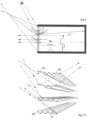
- Figs 1 and 2 illustrate typical slat contours for the lower window region and the upper window region, which were developed from the standpoint of production, the positively locked slat contour and the stacking in a slat assembly and also the bifocal light directing and freedom from glare.
- "Bifocal” means that one part of the impinging radiation is directed into the interior in a focusing manner and a further part is directed outwards in a focusing manner.
- "Deflected inwards” is synonymous with "into the half-space located opposite the half-space of the lateral light incidence”.
- "Deflected outwards” is synonymous with a reflection back into the half-space of the lateral light incidence.
- Light incidence should be understood to mean a light incidence from the upper half-space - that is to say from the direction of the sky - preferably with large elevation angles.
- the term “light deflection” is synonymous with light reflections, wherein “light deflection” should also be understood to mean a plurality of reflections.
- a roller set firstly the profile for the upper light region ( Fig. 1 ) is produced. Only in the course of further passes does the basic profile arise ( Fig. 2 ), by virtue of the edge zone RZ being shaped further in an angular fashion, this then resulting in a fold side facing the lateral incidence and a fold side facing away relative to the lateral light.
- Fig. 3 in the wings there is a bend in the edge zones, said bend, in terms of its position, preparing the approximately right-angled shaping of the basic profile and simultaneously stiffening and stabilizing the edge zones.
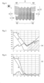
- the figures show the reflection behaviour of the slats in a horizontal slat position for 30°, 40° and 50° sun incidence.
- the edge zone RZ i located towards the interior is embodied likewise in a bent fashion purely by way of example, the slat edge RZ i2 having an angle of min. 20°.
- Reflected solar radiation 25 that is incident on the segment RZ i1 from below is deflected > 0° into the interior depth without producing glare.
- the first segment RZ i1 is advantageously designed to be ⁇ 0° in order that the reflected radiation 25 is not deflected shallowly into the user's eye in the interior, but rather steeply downwards to the floor plane.
- Deflected solar radiation 26 impinges on segment RZ i2 and is deflected to the interior ceiling and into the interior depth.
- the slat shapings illustrated here should be considered particularly in the case of slat surfaces which on both sides are specularly reflective or are at least metallically reflective or lacquered with high gloss, even though the innovation is not restricted thereto.
- a coloured or matt white slat underside also belongs to the scope of protection of the invention.
- freeform shapes developed primarily from the standpoint of light deflection at the slat top sides can also be chosen for the edge zones RZ.
- the innovative, optimized slat contour determination ensures, even in the case of a white lustrous underside, that glare does not occur since even a white surface impinged on by sunlight produces a high degree of glare.
- the advantage of the slat configuration for a blind hanging is that the different slats in Fig. 4 can be fitted together.
- the slats can be shaped using an identical roller tool. It is only starting from a specific pass starting from which the outer folds are shaped in the edge zones RZ that further roller set pairs are used to shape the slats for the lower window region. This shaping exhibits the dashed contour 27 and 28.
- edge zones RZ of the bifocal slats in Figs 1, 2 , 3 , 7 are angled in each case such that in a further shaping with respect to the basic slat the bend points of the folds are prepared by incipient bending ( Fig. 3 ).
- Other shapings from the standpoint of particular light guidance with displaced bend points or as a plane or as concave curvature are possible.
- Fig. 4 shows three slat types.
- the bottommost and middle slats 30, 31 and also the middle and upper slats 30, 32 fit together in a positively locking manner.
- the middle slats exhibit only an edge zone RZ embodied in an extended fashion on the longitudinal edge located towards the lateral light incidence.
- the present slat assembly could produce a hanging zoned in a tripartite fashion, which realizes a differentiated total energy and light transmission within the hanging.
- Figs 7 and 8 show the light distribution at the slats from Figs 1 and 2 of 50° light incidence into the half-spaces 50 and 51.
- the illustrations respectively show the light distribution into the upper half-space 52 of the lateral light incidence 46 and into the upper half-space 52 opposite the lateral light incidence.
- Fig. 7 shows the bifocal property of the light deflection into the half-space 50 and 51
- Fig. 8 shows the monofocal light reflection back into the half-space 50. A light deflection into the lower half-space 53 is largely avoided.
- Figs 5 and 6 show the transmission behaviour between two slats from Fig. 1 and Fig. 2 , respectively, into the half-space opposite the half-space of the light incidence - that is to say into an interior.
- the angles of incidence of sunlight are depicted on the abscissa, and the light transmission in percent on the ordinate.
- the directing of light into an interior by the slats from Fig. 1 is evident in Fig. 5 in comparison with the table in Fig. 6 from the increased energy or light irradiation at angles of incidence of between 40° and 70°.
- the more the lateral light irradiation approaches the zenith the greater the light transmission into the opposite half-space or into the interior.
- Curves a show the total light and energy transmission (absorption plus direct insolation including reflected radiation) as a function of the lateral light incidence.
- Curves b show proportionally the directly incident radiation between the slats and curves c show proportionally the light reflected at the edge zones RZ including diffuse radiation portions owing to edge roundings at the fold vertices.
- a very good reduction 33 in Fig. 6 can be achieved for the high direct sunlight in summer.
- the dashed region 34 in Fig. 5 shows the gain for zenith radiation by way of the edge zones RZ in Fig. 1 .
- the sizes of the hanging zones with slats in accordance with Fig. 1 and 2 are dimensioned depending on degree of latitude, sky direction, local climate, etc.
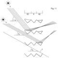
- Fig. 10 shows a perspective illustration of further salts similar to the slats from Fig. 1 and 2 , but with a smaller contour zone K with only two folds.
- the slats can have any desired number of folds, but at least three folds on the slat top side of the slats in the lower window region and one fold in the upper window region.
- the slats in Fig. 10 for the lower window region have a first and respectively a last shaded fold side 40, 41.
- the edge zones 42, 43 of the upper slats are impinged on by sunlight, without forming a shaded fold side - at least not for relatively steep angles of incidence of sunlight.
- the term "lateral light” should be understood primarily to mean radiation from the upper half-space distinctly above the horizon.
- FIG. 9 A typical application of the slats in Figs 1 and 2 is shown in Fig. 9 .
- eye height - that is to say starting approximately from 1.70 m - a change of the slat types takes place.
- the lower window region directs light out monofocally and suppresses glare;
- the upper window region is bifocal with directing in of zenith light and also such that it directs in shallower sunlight into the interior depth.
- Fig. 11 shows a further slat configuration by virtue of the fact that, from a monofocal base slat for the lower window region, a bifocal slat for the upper window region is produced by means of wrapped appendages 12, 13.
- the optical system is superimposed on the base slat.
- Production is carried out by means of a common roller tool for the base profile and the base profile is overlapped by the appendages 12, 13 in downstream tools.
- the advantage is that no tool change is required. Only the feed-in width of the flat strip changes depending on the desired contour.
- focus or "focusing” be understood in a restrictive way as a punctiform collection of reflections. It merely clarifies that individual reflections cross one another and many reflections form a focusing zone.
Landscapes
- Engineering & Computer Science (AREA)
- Structural Engineering (AREA)
- Architecture (AREA)
- Civil Engineering (AREA)
- Blinds (AREA)
- Non-Portable Lighting Devices Or Systems Thereof (AREA)
Claims (9)
- Stapelbare Lamellen zur Lichtlenkung als Vorprodukt für Jalousie-Sonnenschutzbehänge zur Lenkung von einstrahlendem Sonnenlicht als Seitenlicht, bestehend aus Lamellen mit metallischem Reflektorglanz zumindest an den Lamellenoberseiten, wobeidie Lamellen zumindest teilweise winklig in Längsrichtung gefaltet sind und sich in einer horizontalen Lamellenstellung ein oberer Faltenwinkel β1 und ein unterer Faltenwinkel β2 zwischen den Faltenseiten ergeben, wobeimindestens ein Teil der Falten jeweils eine seitliche Lichteinstrahlungsseite und eine seitliche Lichtschattenseite aufweist, so dass aufgrund der Neigungswinkel der Faltenseiten mindestens eine seitliche Lichteinstrahlungsseite im Einbauzustand dem einfallenden Sonnenlicht als Seitenlicht zugewandt ist und eine seitliche Lichtschattenseite dem Seitenlicht aus dem oberen Halbraum abgewandt ist, wodurch die Falten einen Faltenwinkel β1 bilden, und wobeimindestens zwei übereinander liegende Lamellen zumindest teilweise eine faltenförmige Kernzone K aufweisen, in der die Lamellen komplementär ineinandergelegt werden können und mindestens eine Randzone RZ aufweisen,dadurch gekennzeichnet, dass- eine im Einbauzustand zumindest in einer Randzone RZ auf der seitlichen Lichteinfallsseite auf einer Unterlamelle aufliegende Oberlamelle mindestens einen größeren Faltenwinkel β3 und/oder β4 gegenüber den Faltenwinkeln β2 in der Kernzone K aufweist und in Längsrichtung gebogen und/oder gekrümmt und/oder gestreckt ausgebildet ist und ohne eine dem sehr hohen seitlichen Lichteinfall abgewandte Faltenseite ausgebildet ist, so dass- mindestens eine Randzone RZ einer oberen Lamelle anders geformt ist als eine Randzone RZ einer unteren Lamelle, wobei- die Kontur in der Randzone RZ einer darüberliegenden Lamelle nicht formkompatibel mit der Randzone RZ einer unteren Lamellenkontur sein muss, und- die Randzone RZ der oberen Lamelle ohne eine von den sehr hohen seitlichen Lichteinfallswinkeln abgewandte Faltenseite ausgebildet ist, so dass- ein Lamellenpaar trotz unterschiedlicher Querschnittskonturen in den Randzonen RZ der oberen und unteren Lamelle zu einer Jalousieanordnung stapelbar ist, wobei- im Bereich der Kernzone K der oberen und unteren Lamellentypen auf der Seite des seitlichen Lichteinfalls seitliches Licht in Richtung desjenigen Halbraumes zurückreflektiert werden kann, aus dem das seitliche Licht einfällt, und dass- an der oberen Lamelle seitliches Licht zumindest teilweise an einer Randzone RZ in Richtung desjenigen Halbraumes umlenkbar ist, der dem Halbraum des seitlichen Lichteinfalls gegenüberliegt, und dass- an der Unterlamelle seitliches Licht zumindest in der Randzone RZ auf der seitlichen Lichteinfallsseite in den Halbraum, aus dem das seitliche Licht einfällt, zurückreflektiert werden kann, so dass- mit den Lamellenvorprodukten bifokale Jalousie-Sonnenschutzbehänge herstellbar sind, durch die im unteren Behangbereich durch die unteren Lamellen seitliches Licht im Wesentlichen in den Halbraum des Lichteinfalls zurückreflektiert wird und im oberen Bereich des Jalousie-Sonnenschutzbehanges durch die darüberliegenden Lamellen seitliches Licht mit hohen Einfallswinkeln von der Sonne zumindest teilweise in den dem seitlichen Lichteinfall gegenüberliegenden Halbraum reflektiert werden kann und über die formkomplementäre Konturzone K in den Halbraum des Lichteinfalls zurückreflektiert werden kann.
- Lamellen nach Anspruch 1, dadurch gekennzeichnet, dass die Randzonen RZ der aufliegenden Lamellen einen Faltenwinkel β3/β4 aufweisen, der > β2 dem Faltenwinkel in der Kernzone K ist, so dass die Konturen der Randzone RZ der aufliegenden Lamelle selbsttragende Flügelelemente bilden, die als Lichtreflektoren dienen und einen Reflexionsfokus in dem dem Halbraum des Lichteinfalls gegenüberliegenden Halbraum bilden.
- Lamellen nach Anspruch 1, dadurch gekennzeichnet, dass die oberen Lamellen in der Randzone RZ verlängert und/oder gebogen und/oder geknickt oder durch auf die Profiloberseite aufgelegte Verlängerungen gebildet sind.
- Lamellen nach Anspruch 1, dadurch gekennzeichnet, dass die Lamellenkante RZ1 einer oberen Lamelle in Bezug auf die seitliche Lichteinfallsseite hinsichtlich ihrer Winkelneigung zur Horizontalen so steil angeordnet ist, dass auf die Unterseite der Lamellenkante RZi auftreffendes flaches Sonnenlicht (23) < αs unter einem Winkel > αs, dem Winkel der Schattenlinie zwischen einer oberen und einer unteren Lamelle, im Wesentlichen auf die Oberseite der unteren Lamelle reflektiert werden kann.
- Lichtlenkende Lamellen nach Anspruch 1, dadurch gekennzeichnet, dass die Randzone RZ in dem dem seitlichen Lichteinfall gegenüberliegenden Halbraum so gekrümmt ausgebildet ist, dass von unten einfallendes reflektiertes Sonnenlicht (25) in einem ersten Segment Rzi1 - wenn die Lamellen als Jalousie in einem Fenster eingebaut sind - auf die Bodenebene (100) reflektiert werden kann und seitlich einfallendes Licht (26) in einem zweiten Segment Rzi2 > 0° in den Innenraum (102) reflektiert werden kann.
- Lamellen nach Anspruch 1, dadurch gekennzeichnet, dass Sehnen durch die Lamellenkanten RZ um 0° bis 30° gegenüber der Horizontalen geneigt sind und flach einfallendes seitliches Licht unter einem flachen Winkel gegenüber der Horizontalen insbesondere in Winkeln von 0° bis 90° in den dem seitlichen Lichteinfall gegenüberliegenden Halbraum umlenkbar ist.
- Lichtlenkende Lamellen nach Anspruch 1, dadurch gekennzeichnet, dass mindestens eine Falte in der Randzone RZ auf der seitlichen Lichteinstrahlungsseite und/oder auf der dem seitlichen Lichteinfall abgewandten Seite zumindest teilweise von nach oben umgelegte Verlängerungen (12, 13) überdeckt ist und dass auf diese auftreffendes seitliches Licht zumindest teilweise in den dem seitlichen Lichteinfall gegenüberliegenden Halbraum umlenkbar ist, so dass eine bifokale Lichtumlenkung entsteht, wobei jeder der Verlängerungen (12, 13) einen Fokus erzeugt.
- Lamellen nach einem der Ansprüche 1 bis 3, dadurch gekennzeichnet, dass zumindest die unterste Lamelle für einen oberen Fensterbereich (32) in zumindest die oberste Lamelle im unteren Fensterbereich (30) einlegbar ist, wobei insbesondere die Lamellen für einen oberen Fensterbereich (32) und/oder die Lamellen für einen unteren Fensterbereich (30) jeweils zu einem Lamellenverbund zusammenfügbar sind, wobei besonders bevorzugt alle Lamellen zu einem Lamellenverbund zusammenfügbar sind.
- Fensterbehang aus einer Vielzahl von Lamellen nach einem der Ansprüche 1 bis 9 mit lichtreflektierenden Lamellenoberseiten, wobei die Lamellen im Querschnitt eine Faltenstruktur (K) aufweisen und der Fensterbehang aus mindestens zwei Lamellentypen mit unterschiedlichen Konturen für einen oberen und einen unteren Fensterbereich besteht,
dadurch gekennzeichnet, dass- die Lamellen für den oberen Fensterbereich und für den unteren Fensterbereich zumindest in der Lamellenquerschnittsmitte eine Faltenkontur K aufweisen, und- die Lamellen im oberen Fensterbereich auf der seitlichen Lichteinfallsseite und/oder auf der dem seitlichen Lichteinfall gegenüberliegenden Seite des Halbraumes unterschiedliche Konturen in den Randzonen RZ aufweisen, die so ausgebildet sind, dass- die Lamellen stapelbar sind und- im oberen Fensterbereich nur die in der Kernzone K einfallende Einstrahlung in den oberen Halbraum auf der Seite dieses seitlichen Lichteinfalls zurückreflektierbar ist und auf die Lamellenrandzonen RZ einfallende seitliche Strahlung zumindest teilweise in Richtung des dem seitlichen Lichteinfall gegenüberliegenden Halbraums umlenkbar ist, so dass- insbesondere Zenitstrahlung über einen für einen oberen Lichtbereich vorgesehenen Abschnitt des Fensterbehangs in den dem seitlichen Lichteinfall gegenüberliegenden Halbraum umlenkbar ist.
Applications Claiming Priority (4)
| Application Number | Priority Date | Filing Date | Title |
|---|---|---|---|
| DE102019206495.7A DE102019206495B4 (de) | 2019-05-06 | 2019-05-06 | Retroreflektierende fensterbehänge |
| DE102019206497.3A DE102019206497A1 (de) | 2018-06-19 | 2019-05-06 | Dichotome, bifokale lichtlenklamellensysteme |
| DE102019207768.4A DE102019207768A1 (de) | 2019-05-27 | 2019-05-27 | Bifokale fensterbehänge |
| PCT/EP2020/062475 WO2020225266A1 (en) | 2019-05-06 | 2020-05-05 | Stackable, mono- and bifocal slats for deflecting light |
Publications (3)
| Publication Number | Publication Date |
|---|---|
| EP3976919A1 EP3976919A1 (de) | 2022-04-06 |
| EP3976919C0 EP3976919C0 (de) | 2025-04-16 |
| EP3976919B1 true EP3976919B1 (de) | 2025-04-16 |
Family
ID=73050555
Family Applications (1)
| Application Number | Title | Priority Date | Filing Date |
|---|---|---|---|
| EP20724095.3A Active EP3976919B1 (de) | 2019-05-06 | 2020-05-05 | Stapelbare, mono- und bifokale lamellen zum ablenken von licht |
Country Status (5)
| Country | Link |
|---|---|
| US (1) | US20250223869A1 (de) |
| EP (1) | EP3976919B1 (de) |
| AU (2) | AU2020269906B2 (de) |
| CA (1) | CA3139565A1 (de) |
| WO (1) | WO2020225266A1 (de) |
Cited By (1)
| Publication number | Priority date | Publication date | Assignee | Title |
|---|---|---|---|---|
| DE102024002618A1 (de) | 2024-08-13 | 2026-02-19 | Helmut Köster | Lichtreflektierendes Bandmaterial |
Families Citing this family (2)
| Publication number | Priority date | Publication date | Assignee | Title |
|---|---|---|---|---|
| US20250207460A1 (en) | 2022-03-28 | 2025-06-26 | Helmut Köster | Light deflection systems with mirror reflection lenses |
| DE102022203040A1 (de) | 2022-03-28 | 2023-09-28 | Helmut Köster | Bifokale lamellen |
Family Cites Families (7)
| Publication number | Priority date | Publication date | Assignee | Title |
|---|---|---|---|---|
| AU704884B2 (en) * | 1994-09-17 | 1999-05-06 | Helmut Koster | Stepped lamella for guiding light radiation |
| DE19828542A1 (de) * | 1997-12-09 | 1999-07-01 | Koester Helmut Dipl Ing Archit | Sonnenschutzanlage für Sonnenschutzlamellen, die eine gezahnte Oberseite aufweisen |
| DE19929141A1 (de) * | 1998-06-26 | 2000-04-27 | Helmut Koester | Gezahnte Tageslichtlamelle |
| CA2292763A1 (en) * | 1998-12-18 | 2000-06-18 | James Love | Window blinds |
| AU758794B2 (en) * | 1999-06-26 | 2003-03-27 | Helmut Koster | Toothed daylight blinds |
| EP3411555B1 (de) * | 2016-02-02 | 2025-09-10 | Köster, Helmut | Jalousie mit lichtleitlamellen |
| DE102018209297B3 (de) * | 2018-06-11 | 2019-12-12 | Helmut Köster | Blendfreie Tageslichtlamellen |
-
2020
- 2020-05-05 WO PCT/EP2020/062475 patent/WO2020225266A1/en not_active Ceased
- 2020-05-05 AU AU2020269906A patent/AU2020269906B2/en active Active
- 2020-05-05 CA CA3139565A patent/CA3139565A1/en active Pending
- 2020-05-05 US US17/609,297 patent/US20250223869A1/en active Pending
- 2020-05-05 EP EP20724095.3A patent/EP3976919B1/de active Active
-
2025
- 2025-09-25 AU AU2025238044A patent/AU2025238044A1/en not_active Abandoned
Cited By (1)
| Publication number | Priority date | Publication date | Assignee | Title |
|---|---|---|---|---|
| DE102024002618A1 (de) | 2024-08-13 | 2026-02-19 | Helmut Köster | Lichtreflektierendes Bandmaterial |
Also Published As
| Publication number | Publication date |
|---|---|
| WO2020225266A1 (en) | 2020-11-12 |
| EP3976919A1 (de) | 2022-04-06 |
| AU2020269906B2 (en) | 2025-06-26 |
| EP3976919C0 (de) | 2025-04-16 |
| WO2020225266A4 (en) | 2021-01-14 |
| AU2025238044A1 (en) | 2025-10-16 |
| AU2020269906A1 (en) | 2021-12-02 |
| US20250223869A1 (en) | 2025-07-10 |
| CA3139565A1 (en) | 2020-11-12 |
Similar Documents
| Publication | Publication Date | Title |
|---|---|---|
| EP3976919B1 (de) | Stapelbare, mono- und bifokale lamellen zum ablenken von licht | |
| NL1010766C2 (nl) | Zonwering met zonweringlamellen voorzien van een getande bovenzijde. | |
| US4509825A (en) | Directing and controlling the distribution of radiant energy | |
| AU704884B2 (en) | Stepped lamella for guiding light radiation | |
| EP2534329B1 (de) | Z-foermige jalousie-lamelle zum reflektieren des tageslichts | |
| EP2935750B1 (de) | Lichtlenklamelle, verfahren zur herstellung, anwendung und sonnenschutzsystem | |
| EP2392032A1 (de) | Fensteranordnung mit solarzellen | |
| US6227280B1 (en) | Sunshade of the type of a venetian blind | |
| EP3411555B1 (de) | Jalousie mit lichtleitlamellen | |
| US20250207460A1 (en) | Light deflection systems with mirror reflection lenses | |
| WO1996023950A2 (en) | Venetian blind for guiding the daylight comprising edged lamellae | |
| US10513851B2 (en) | Curved reflective skylight curb insert to diffuse incident sunlight in the azimuthal direction | |
| KR100592426B1 (ko) | 독립형 자연채광장치 | |
| EP2507465A2 (de) | Lichtleiterlamellen mit abgeflachten zahnstrukturen | |
| US20220252234A1 (en) | Devices for Internal Daylighting with IR rejection | |
| CA2205560C (en) | Sun-shade with stepped lamellae for guiding light radiation | |
| HK1213614B (en) | Wind-up light-directing slat, method of production, application, and sun protection system |
Legal Events
| Date | Code | Title | Description |
|---|---|---|---|
| STAA | Information on the status of an ep patent application or granted ep patent |
Free format text: STATUS: UNKNOWN |
|
| STAA | Information on the status of an ep patent application or granted ep patent |
Free format text: STATUS: THE INTERNATIONAL PUBLICATION HAS BEEN MADE |
|
| PUAI | Public reference made under article 153(3) epc to a published international application that has entered the european phase |
Free format text: ORIGINAL CODE: 0009012 |
|
| STAA | Information on the status of an ep patent application or granted ep patent |
Free format text: STATUS: REQUEST FOR EXAMINATION WAS MADE |
|
| 17P | Request for examination filed |
Effective date: 20211202 |
|
| AK | Designated contracting states |
Kind code of ref document: A1 Designated state(s): AL AT BE BG CH CY CZ DE DK EE ES FI FR GB GR HR HU IE IS IT LI LT LU LV MC MK MT NL NO PL PT RO RS SE SI SK SM TR |
|
| DAV | Request for validation of the european patent (deleted) | ||
| DAX | Request for extension of the european patent (deleted) | ||
| GRAP | Despatch of communication of intention to grant a patent |
Free format text: ORIGINAL CODE: EPIDOSNIGR1 |
|
| STAA | Information on the status of an ep patent application or granted ep patent |
Free format text: STATUS: GRANT OF PATENT IS INTENDED |
|
| INTG | Intention to grant announced |
Effective date: 20240320 |
|
| GRAS | Grant fee paid |
Free format text: ORIGINAL CODE: EPIDOSNIGR3 |
|
| GRAJ | Information related to disapproval of communication of intention to grant by the applicant or resumption of examination proceedings by the epo deleted |
Free format text: ORIGINAL CODE: EPIDOSDIGR1 |
|
| GRAL | Information related to payment of fee for publishing/printing deleted |
Free format text: ORIGINAL CODE: EPIDOSDIGR3 |
|
| STAA | Information on the status of an ep patent application or granted ep patent |
Free format text: STATUS: REQUEST FOR EXAMINATION WAS MADE |
|
| INTC | Intention to grant announced (deleted) | ||
| GRAP | Despatch of communication of intention to grant a patent |
Free format text: ORIGINAL CODE: EPIDOSNIGR1 |
|
| STAA | Information on the status of an ep patent application or granted ep patent |
Free format text: STATUS: GRANT OF PATENT IS INTENDED |
|
| INTG | Intention to grant announced |
Effective date: 20240925 |
|
| GRAJ | Information related to disapproval of communication of intention to grant by the applicant or resumption of examination proceedings by the epo deleted |
Free format text: ORIGINAL CODE: EPIDOSDIGR1 |
|
| GRAL | Information related to payment of fee for publishing/printing deleted |
Free format text: ORIGINAL CODE: EPIDOSDIGR3 |
|
| STAA | Information on the status of an ep patent application or granted ep patent |
Free format text: STATUS: REQUEST FOR EXAMINATION WAS MADE |
|
| GRAP | Despatch of communication of intention to grant a patent |
Free format text: ORIGINAL CODE: EPIDOSNIGR1 |
|
| STAA | Information on the status of an ep patent application or granted ep patent |
Free format text: STATUS: GRANT OF PATENT IS INTENDED |
|
| GRAA | (expected) grant |
Free format text: ORIGINAL CODE: 0009210 |
|
| STAA | Information on the status of an ep patent application or granted ep patent |
Free format text: STATUS: THE PATENT HAS BEEN GRANTED |
|
| INTC | Intention to grant announced (deleted) | ||
| INTG | Intention to grant announced |
Effective date: 20250227 |
|
| AK | Designated contracting states |
Kind code of ref document: B1 Designated state(s): AL AT BE BG CH CY CZ DE DK EE ES FI FR GB GR HR HU IE IS IT LI LT LU LV MC MK MT NL NO PL PT RO RS SE SI SK SM TR |
|
| REG | Reference to a national code |
Ref country code: GB Ref legal event code: FG4D |
|
| REG | Reference to a national code |
Ref country code: CH Ref legal event code: EP Ref country code: DE Ref legal event code: R096 Ref document number: 602020049519 Country of ref document: DE |
|
| REG | Reference to a national code |
Ref country code: IE Ref legal event code: FG4D |
|
| U01 | Request for unitary effect filed |
Effective date: 20250416 |
|
| U07 | Unitary effect registered |
Designated state(s): AT BE BG DE DK EE FI FR IT LT LU LV MT NL PT RO SE SI Effective date: 20250530 |
|
| U20 | Renewal fee for the european patent with unitary effect paid |
Year of fee payment: 6 Effective date: 20250730 |
|
| PG25 | Lapsed in a contracting state [announced via postgrant information from national office to epo] |
Ref country code: ES Free format text: LAPSE BECAUSE OF FAILURE TO SUBMIT A TRANSLATION OF THE DESCRIPTION OR TO PAY THE FEE WITHIN THE PRESCRIBED TIME-LIMIT Effective date: 20250416 |
|
| PG25 | Lapsed in a contracting state [announced via postgrant information from national office to epo] |
Ref country code: NO Free format text: LAPSE BECAUSE OF FAILURE TO SUBMIT A TRANSLATION OF THE DESCRIPTION OR TO PAY THE FEE WITHIN THE PRESCRIBED TIME-LIMIT Effective date: 20250716 Ref country code: GR Free format text: LAPSE BECAUSE OF FAILURE TO SUBMIT A TRANSLATION OF THE DESCRIPTION OR TO PAY THE FEE WITHIN THE PRESCRIBED TIME-LIMIT Effective date: 20250717 |
|
| PG25 | Lapsed in a contracting state [announced via postgrant information from national office to epo] |
Ref country code: PL Free format text: LAPSE BECAUSE OF FAILURE TO SUBMIT A TRANSLATION OF THE DESCRIPTION OR TO PAY THE FEE WITHIN THE PRESCRIBED TIME-LIMIT Effective date: 20250416 |
|
| PG25 | Lapsed in a contracting state [announced via postgrant information from national office to epo] |
Ref country code: HR Free format text: LAPSE BECAUSE OF FAILURE TO SUBMIT A TRANSLATION OF THE DESCRIPTION OR TO PAY THE FEE WITHIN THE PRESCRIBED TIME-LIMIT Effective date: 20250416 |
|
| PG25 | Lapsed in a contracting state [announced via postgrant information from national office to epo] |
Ref country code: RS Free format text: LAPSE BECAUSE OF FAILURE TO SUBMIT A TRANSLATION OF THE DESCRIPTION OR TO PAY THE FEE WITHIN THE PRESCRIBED TIME-LIMIT Effective date: 20250716 |
|
| PG25 | Lapsed in a contracting state [announced via postgrant information from national office to epo] |
Ref country code: IS Free format text: LAPSE BECAUSE OF FAILURE TO SUBMIT A TRANSLATION OF THE DESCRIPTION OR TO PAY THE FEE WITHIN THE PRESCRIBED TIME-LIMIT Effective date: 20250816 |
|
| REG | Reference to a national code |
Ref country code: CH Ref legal event code: H13 Free format text: ST27 STATUS EVENT CODE: U-0-0-H10-H13 (AS PROVIDED BY THE NATIONAL OFFICE) Effective date: 20251223 |
|
| PG25 | Lapsed in a contracting state [announced via postgrant information from national office to epo] |
Ref country code: SM Free format text: LAPSE BECAUSE OF FAILURE TO SUBMIT A TRANSLATION OF THE DESCRIPTION OR TO PAY THE FEE WITHIN THE PRESCRIBED TIME-LIMIT Effective date: 20250416 |
|
| PG25 | Lapsed in a contracting state [announced via postgrant information from national office to epo] |
Ref country code: CH Free format text: LAPSE BECAUSE OF NON-PAYMENT OF DUE FEES Effective date: 20250531 |
|
| PG25 | Lapsed in a contracting state [announced via postgrant information from national office to epo] |
Ref country code: CZ Free format text: LAPSE BECAUSE OF FAILURE TO SUBMIT A TRANSLATION OF THE DESCRIPTION OR TO PAY THE FEE WITHIN THE PRESCRIBED TIME-LIMIT Effective date: 20250416 |
|
| PG25 | Lapsed in a contracting state [announced via postgrant information from national office to epo] |
Ref country code: SK Free format text: LAPSE BECAUSE OF FAILURE TO SUBMIT A TRANSLATION OF THE DESCRIPTION OR TO PAY THE FEE WITHIN THE PRESCRIBED TIME-LIMIT Effective date: 20250416 |
|
| PG25 | Lapsed in a contracting state [announced via postgrant information from national office to epo] |
Ref country code: MC Free format text: LAPSE BECAUSE OF FAILURE TO SUBMIT A TRANSLATION OF THE DESCRIPTION OR TO PAY THE FEE WITHIN THE PRESCRIBED TIME-LIMIT Effective date: 20250416 |
|
| PLBE | No opposition filed within time limit |
Free format text: ORIGINAL CODE: 0009261 |
|
| STAA | Information on the status of an ep patent application or granted ep patent |
Free format text: STATUS: NO OPPOSITION FILED WITHIN TIME LIMIT |
|
| REG | Reference to a national code |
Ref country code: CH Ref legal event code: L10 Free format text: ST27 STATUS EVENT CODE: U-0-0-L10-L00 (AS PROVIDED BY THE NATIONAL OFFICE) Effective date: 20260225 |
|
| 26N | No opposition filed |
Effective date: 20260119 |
|
| GBPC | Gb: european patent ceased through non-payment of renewal fee |
Effective date: 20250716 |
|
| PG25 | Lapsed in a contracting state [announced via postgrant information from national office to epo] |
Ref country code: GB Free format text: LAPSE BECAUSE OF NON-PAYMENT OF DUE FEES Effective date: 20250716 |
|
| PG25 | Lapsed in a contracting state [announced via postgrant information from national office to epo] |
Ref country code: IE Free format text: LAPSE BECAUSE OF NON-PAYMENT OF DUE FEES Effective date: 20250505 |