EP3976869B1 - Verfahren zur herstellung eines ringsektors - Google Patents
Verfahren zur herstellung eines ringsektors Download PDFInfo
- Publication number
- EP3976869B1 EP3976869B1 EP20742798.0A EP20742798A EP3976869B1 EP 3976869 B1 EP3976869 B1 EP 3976869B1 EP 20742798 A EP20742798 A EP 20742798A EP 3976869 B1 EP3976869 B1 EP 3976869B1
- Authority
- EP
- European Patent Office
- Prior art keywords
- fibrous structure
- warp
- weft
- spacing
- fibrous
- Prior art date
- Legal status (The legal status is an assumption and is not a legal conclusion. Google has not performed a legal analysis and makes no representation as to the accuracy of the status listed.)
- Active
Links
Images

Classifications
-
- D—TEXTILES; PAPER
- D03—WEAVING
- D03D—WOVEN FABRICS; METHODS OF WEAVING; LOOMS
- D03D25/00—Woven fabrics not otherwise provided for
- D03D25/005—Three-dimensional woven fabrics
-
- B—PERFORMING OPERATIONS; TRANSPORTING
- B29—WORKING OF PLASTICS; WORKING OF SUBSTANCES IN A PLASTIC STATE IN GENERAL
- B29B—PREPARATION OR PRETREATMENT OF THE MATERIAL TO BE SHAPED; MAKING GRANULES OR PREFORMS; RECOVERY OF PLASTICS OR OTHER CONSTITUENTS OF WASTE MATERIAL CONTAINING PLASTICS
- B29B11/00—Making preforms
- B29B11/14—Making preforms characterised by structure or composition
- B29B11/16—Making preforms characterised by structure or composition comprising fillers or reinforcement
-
- D—TEXTILES; PAPER
- D03—WEAVING
- D03D—WOVEN FABRICS; METHODS OF WEAVING; LOOMS
- D03D41/00—Looms not otherwise provided for, e.g. for weaving chenille yarn; Details peculiar to these looms
- D03D41/004—Looms for three-dimensional fabrics
-
- D—TEXTILES; PAPER
- D06—TREATMENT OF TEXTILES OR THE LIKE; LAUNDERING; FLEXIBLE MATERIALS NOT OTHERWISE PROVIDED FOR
- D06M—TREATMENT, NOT PROVIDED FOR ELSEWHERE IN CLASS D06, OF FIBRES, THREADS, YARNS, FABRICS, FEATHERS OR FIBROUS GOODS MADE FROM SUCH MATERIALS
- D06M23/00—Treatment of fibres, threads, yarns, fabrics or fibrous goods made from such materials, characterised by the process
-
- Y—GENERAL TAGGING OF NEW TECHNOLOGICAL DEVELOPMENTS; GENERAL TAGGING OF CROSS-SECTIONAL TECHNOLOGIES SPANNING OVER SEVERAL SECTIONS OF THE IPC; TECHNICAL SUBJECTS COVERED BY FORMER USPC CROSS-REFERENCE ART COLLECTIONS [XRACs] AND DIGESTS
- Y02—TECHNOLOGIES OR APPLICATIONS FOR MITIGATION OR ADAPTATION AGAINST CLIMATE CHANGE
- Y02T—CLIMATE CHANGE MITIGATION TECHNOLOGIES RELATED TO TRANSPORTATION
- Y02T50/00—Aeronautics or air transport
- Y02T50/60—Efficient propulsion technologies, e.g. for aircraft
Definitions
- the present invention relates to the manufacture of a fibrous structure for the production of composite parts intended to be integrated, for example, into a turbomachine.
- CMC parts are increasingly used to replace metal parts integrated into turbomachinery.
- CMC parts have particularly interesting high-temperature mechanical properties, ideal for the design, for example, of stators or turbine distributors.
- sectored CMC parts are arranged and assembled on a metal casing, and connected together by sealed connections, in order to ensure the sealing of the vein despite the thermal expansion caused by high operating temperatures.
- the CMC materials used are based on SiC fibers and SiC matrix.
- SiC fibers are integrated into the CMC material in the form of fibrous structures, obtained, for example, by three-dimensional weaving.
- This is a multi-layer weave using several layers of weft yarns and several layers of warp yarns, with warp yarns that bind together different layers of weft yarns.
- Different types of 3D weave weaves can be used, for example interlock, multi-satin, multi-plain, multi-twill weaves.
- FIG. 1 represents a stator sector 2 which is intended to be mounted radially opposite the tips of moving blades. It comprises two radial flanges 4 spaced axially from each other and connected internally to an annular wall sector 6 which comprises a central portion 8 connecting the two flanges 4 and spoilers 10 extending in opposite directions from the axial ends of the central portion 8.
- the terms "radial” and “axial” are to be considered in relation to the axis A of the angular sector, this axis corresponding to the axis around which a plurality of sectors are intended to be arranged to surround a bladed wheel.
- the central portion 8 also called a bathtub has a thickness e pc greater than the thickness of the spoilers e b .
- the thickness is measured in the radial direction. This is directly linked to the manufacturing process of the fibrous structure 12.
- This fibrous structure 12 comprises a central portion 14 connected, at each of its ends, to a first 16 and a second 18 portions, detached from each other.
- the central portion 14 of the fibrous structure 12 is intended to form the central portion 8 of the ring sector 2 and the first 16 and second 18 portions are intended to form the spoilers 10 and the flanges 4 of the ring sector 2.
- the central portion 14 comprises x layers of woven warps, the first portions 16 each comprise z layers of woven warps and the second portions 18 each comprise y layers of woven warps.
- the layers of warps are arranged according to a thickness, indicated in the figure by the direction E.
- first 16 and second 18 portions make it possible to make them structurally independent of each other and therefore to conform them in different directions in a mold.
- the fibrous structure 12 is obtained, it is shaped in order to have a shape similar to the desired part, i.e. in “Pi” in the example considered, as illustrated in Figure 3
- the first portions 16, on either side of the central part 14, are thus deployed so as to obtain a fiber preform having the “Pi” topology of the ring sector 2 presented in Figure 1 .
- the warp/weft ratio is identical at every point of the woven piece.
- the central part 8 functionally requires a minimum thickness e pc equivalent to the thickness e b of the spoilers 10. It is also conceivable to have a thickness e pc of the central part 8 substantially greater than the thickness e b of the spoilers 10. This excess thickness results in the use of a functionally unnecessary quantity of fibrous material, while this material is an expensive element.
- a so-called "trimming” solution is used in the design of organic matrix composite (OMC) blades.
- OMC organic matrix composite
- This method consists of removing warp and weft yarns from the fiber structure by changing the weave. The removed yarns are then cut, resulting in a fiber structure with a thickness that varies along the warp direction.
- Such a method cannot be used for a CMC ceramic matrix composite part, particularly because of the fragility of the fibers used.
- the trimming method would then weaken the resulting fiber structure, and consequently the preform.
- the invention aims to remedy the aforementioned drawbacks in a reliable, simple and inexpensive manner.
- This document relates firstly to a three-dimensionally woven multi-layer fibrous structure having the same number of warp threads woven at all levels along the warp direction, the fibrous structure comprising, in the warp direction, a first part and a second part, the first part having a thickness, measured in a direction perpendicular to the warp and weft directions, greater than the second part, characterized in that the spacing between two weft planes along the warp direction is greater in the second part than that of the first part, and in that the number of weft threads is less in the second part than that of the first part.
- the thickness of the second part is no longer dependent on the thickness of the first part.
- the fibrous structure then obtained by three-dimensional weaving has a thickness of the first part greater than the thickness of the second part.
- the number of weft threads per weft plane of the second part may be less than the number of weft threads per weft plane of the first part.
- This method is therefore compatible with the production of fibrous structures for CMC parts, because it does not require the use of the trimming method to vary the thickness.
- the first part of the fibrous structure may comprise a first portion and a second portion, the first portion being arranged, in said perpendicular direction, above a second portion and being structurally independent of the second portion, said first portion and second portion of the first part being woven to the second part at a transition from the first part to the second part.
- the first and second portions of the fibrous structure in particular, constitute the elements of the fibrous structure which will form, once shaped, the spoiler and the flange of the ring sector.
- a conformation in directions, preferably perpendicular, of the first and second portions is permitted thanks to this structural independence.
- the number of weft threads may be greater than the number of warp threads in either of the first portion and the second portion.
- Another possibility to reduce the thickness of the second part is to vary the warp-to-weft ratio in the first part, i.e. in the first and second portions of the first part. This allows to reduce the number of layers of warp to be woven in the second part.
- the number of weft threads may be less than the number of warp threads.
- the spacing between two warp planes can be the same between the first part and the second part. In practice, this is easier to achieve than a variable spacing.
- the spacing between two weft planes can be the same between the first part and the second part, and the spacing between two warp planes can be different.
- the fibrous structure may comprise a third part identical to the first part and woven to the second part along the warp direction opposite the first part.
- the third part of the fibrous structure may comprise a first portion and a second portion, the first portion being arranged, in said perpendicular direction, above a second portion and being structurally independent of the second portion, said first portion and second portion of the third part being woven to the second part at a transition from the first part to the second part.
- the number of weft threads per weft plane of the second part is preferably less than the number of weft threads per weft plane of the third part.
- the fibrous structure has an axis of symmetry, similar to the ring sector presented previously.
- the fibrous structure is therefore shaped into "Pi", a shape close to the ring sector that it is desired to produce.
- a fibrous structure can form a preform having a thickness at the level of the second part which may be less than or equal to the thickness of the first part and the third part.
- the second part, forming, in the fiber preform, the central part or tub then has a thickness which is suitable and sufficient with regard to the thermal and mechanical requirements necessary for the use of this part.
- the present document also relates to a method of manufacturing a fibrous structure as described above, in which during the transition in the warp direction from the first part of the fibrous texture to the second part of the fibrous texture, the number of weft threads is reduced and the spacing between two successive weft planes is increased along the warp direction.
- the present document also relates to a method of manufacturing a fibrous structure as described above, in which during the transition in the warp direction from the second part of the fibrous texture to the first part of the fibrous texture, the number of weft threads is increased and the spacing between two successive weft planes is decreased along the warp direction.
- the composite material obtained then contains a reduced quantity of fibrous material, thereby reducing its production cost as well as its mass.
- the fibrous structure woven from SiC fibers preferably has a target volume fiber content of between 25 and 50%.
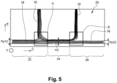
- FIG. 5 is a diagram of a fibrous structure 20 according to the invention on which are represented a warp direction C and a weft direction T and a direction E, these directions being perpendicular two by two.
- This fibrous structure 20 has the same number of warp threads woven at any level of the fibrous structure along the warp direction C.
- the fibrous structure 20 comprises a first part 22, a second part 24 and a third part 26 in the warp direction C, better visible in the schematic illustration of the fibrous structure 20 before shaping.
- the first 22, second 24 and third 26 parts each have a thickness e 1 , e 2 , e 3 measured in a direction E perpendicular to the warp and weft directions.
- the fibrous structure 20 comprises a second part 24 whose thickness e 2 is less than the thickness e 1 , e 2 of each of the first part 22 and the third part 26.
- the first 22 and third 26 parts each comprise a first portion 16 and a second portion 18.
- the first portions 16 of the first 22 and third 26 parts are arranged so as to form a non-zero angle, preferably between 0° and 45°, with the second portions 18 of the first 22 and third 26 parts respectively.
- the first portion 16 is arranged above the second portion 18 in the direction E, also called the direction along the thickness.
- the first 16 and second 18 portions although woven simultaneously, are structurally independent, that is to say they are not woven to each other, which allows an arrangement of the first portions 16, forming a non-zero angle with the second portions 18 and the second part 24.
- the thicknesses e 1 and e 3 are different, and also that the thicknesses e p 11 , e p 31 , e p 12 and e p 32 are different from each other two by two.
- the first portion 16 and the second portion 18 of the first part 22 are woven to the second part 24 at a transition from the first part 22 to the second part 24.
- first portion 16 and second portion 18 of the third part 26 are woven to the second part 24 at a transition from the third part 26 to the second part 24.
- transitions indicated by two boxes A and B, correspond to an interlacing of the threads coming from the first portion 16 and the second portion 18 of the first part 22, to form the second part 24.
- the fibrous structure 20 is characterized by the spacing between two weft planes along the warp direction C which is greater in the second part 24 than that of the first part 22 and the third part 26.
- the number of weft threads is lower in the second part 24 than that of the first part 22 and that of the third part 26. More specifically, the number of weft threads per weft plane of the second part is lower than the number of weft threads per weft plane of the first part. Similarly, the number of weft threads per weft plane of the second part may be lower than the number of weft threads per weft plane of the third part.
- the second part 24 of the fibrous structure 20 thus has a thickness such that e 2 ⁇ e 1 and e 2 ⁇ e 3 .
- Areas Part 1 Part 2 1st portion 2nd portion Number of layers 14 7 21 Number of frame planes 14 7 21 Number of channel plans 14 7 21 Chain spacing (mm) 1.25 1.25 1.25 Frame spacing (mm) 1.25 1.25 1.25 RCT (warp/frame ratio) 50/50 50/50 50/50 Thickness obtained by molding (mm) 4 2 6
- This fibrous structure 12 produced according to the prior art, from 21 textile layers by a three-dimensional multi-layer weaving of the fibrous structure 12 has a warp-weft ratio of 50/50 which is invariant in the different parts of the fibrous structure 12.
- the number of layers, warp planes and wefts of the second part 14 is equal to the sum respectively of the numbers of layers, warp planes and wefts of the first 16 and second 18 portions of the second part 14 (and of the third part where applicable).
- the fibrous structure 20 makes it possible to limit the thickness e 2 of the second part 24, intended to form the bathtub, so that its thickness e 2 is close to the thickness e p 12 of the second portion 18 of the first part 22 (and the third part 26 where appropriate). In other words, e 1 , e 2 and e 3 can thus be different and this without trimming.
- Table 2 illustrates a fibrous structure 20 according to a first embodiment of the invention, comprising a first part 22 and a second part 24 itself comprising a first 16 and a second 18 portion: [Table 2] Areas Part 1 Part 2 1st portion 2nd portion Number of layers 14 7 21 Number of frame planes 14 7 9 Number of channel plans 14 7 21 Chain spacing (mm) 1.25 1.25 1.25 Frame spacing (mm) 1.25 1.25 1.5 RCT (warp/frame ratio) 50/50 50/50 74/26 Thickness obtained by molding (mm) 4 2 4.1
- the thickness e 2 of the second part 24 of this fibrous structure 20, once shaped, is reduced to 4.1 mm, with parameters, for the first 16 and second 18 portions of the first part 22, unchanged compared to table 1 illustrating the prior art.
- the spacing between two weft planes along the warp direction is increased, from 1.25 mm to 1.5 mm, so as to make it greater than the spacing between two consecutive weft planes in the first part 22, in particular in the first 16 and second 18 portions of the first part 22.
- the number of weft threads of the second part 24 is less than the sum of the numbers of weft threads of the first part 22, that is to say the sum of the weft threads of the first 16 and second 18 portions of the first part 22, by locally disengaging weft threads at the transition A between the first 22 and second 24 parts, in order to achieve a warp-weft ratio close to the 75/25 limit.
- the number of weft threads is less than the number of warp threads, respectively 9 and 21.
- the imbalance of the warp-weft ratio is achieved by acting on the spacing between two successive weft planes, and not the spacing between two successive warp planes.
- the spacing between two warp planes is identical between the first part 22 and the second part 24.
- the fibrous structure 20 may include a third portion 26 identical to the first portion 22 and woven to the second portion 24 along the warp direction opposite the first portion 22.
- Table 3 illustrates the characteristics of a fibrous structure 20 according to a second embodiment of the invention, comprising a first part 22 and a second part 24 itself comprising a first 16 and a second 18 portion: [Table 3] Areas Part 1 Part 2 1st portion 2nd portion Number of layers 10 6 16 Number of frame planes 15 7 16 Number of channel plans 10 6 16 Chain spacing (mm) 1.25 1.25 1.25 Frame spacing (mm) 1 1 1.5 RCT (warp/frame ratio) 35/65 41/59 55/45 Thickness obtained by molding (mm) 4.1 2.1 4.2
- the warp-weft ratio is varied in the first 16 and second 18 portions of the first part 22, in order to reduce the number of textile layers woven subsequently in the second part 24.
- the number of weft planes is greater than the number of warp planes.
- the number of weft planes is equal to 1.5 times the number of warp planes.
- the spacing between two successive weft planes in the first 16 and second 18 portions is reduced to 1 mm.
- the number of weft threads is greater than the number of warp threads in the first portion 16 and in the second portion 18 of the first part 22 of the fibrous structure 20.
- the invention also relates to a fibrous structure 22, the thickness e 2 of the second part 24 of which is less than the thickness of the first part 22, that is to say the sum of the thicknesses of the first 16 and second 18 portions.
- Table 4 illustrates a third embodiment of the invention: [Table 4] Areas Part 1 Part 2 1st portion 2nd portion Number of layers 10 6 16 Number of frame planes 15 7 7 Number of channel plans 10 6 16 Chain spacing (mm) 1.25 1.25 1.25 Frame spacing (mm) 1 1 1.5 RCT (warp/frame ratio) 35/65 41/59 73/27 Thickness obtained by molding (mm) 4.1 2.1 3.1
- the thickness of the second part 24 is further reduced, by modifying the warp-weft ratio to 73/27 by reducing the number of weft planes of the second part 24 of the fibrous structure 20, going from 16 to 7.
- the invention also relates to the method of manufacturing the fibrous structures 20 as described with reference to tables 2 to 4.
- the method for manufacturing the weaving of a fibrous structure 20 thus comprises a step consisting of reducing the spacing between two successive weft planes along the warp direction and reducing the number of weft threads during a transition along the warp direction from a first part of the fibrous texture to a second part 24 of the fibrous texture 20 having a thickness greater than that of the first part 22.
- the manufacturing method also comprises a step of increasing the number of weft threads and decreasing the spacing between two successive weft planes along the warp direction, during the transition in the warp direction from the second part 24 of the fibrous texture 20 to the first part 22 of the fibrous texture 20.
- Step b) consists of obtaining from the fibrous structure 20 a fibrous preform intended to form the fibrous reinforcement of the composite part.
- This fibrous preform has a shape close to that of the composite part.
- the woven fibrous structure 20 is shaped in “Pi”, that is to say, the first portions 16 of the first 22 and third 26 parts of the fibrous structure 20 are arranged so as to form an angle with the second portions 18 of the first 22 and third 26 parts and with the second part 24 (the latter three being substantially aligned). This is achieved using shaping tools, making it possible to maintain the preform in a shape close to that of the part to be manufactured.
- the composite part is then obtained by densification of the fiber preform, that is to say by injecting a matrix inside the shaped fiber structure.
- the matrix can be a resin or, in the case of a so-called thermostructural composite material, a refractory material such as carbon or ceramic.
- the matrix injection can be carried out for example by chemical vapor infiltration (CVI), by the process known by the English acronym PIP for Polymer Infiltration And Pyrolysis or any other process classically known for the design of CMC parts.
- CVI chemical vapor infiltration
Landscapes
- Engineering & Computer Science (AREA)
- Textile Engineering (AREA)
- Mechanical Engineering (AREA)
- Woven Fabrics (AREA)
Claims (9)
- Dreidimensional gewebte, mehrlagige Faserstruktur (20) mit einer gleichen Anzahl von auf jeder Ebene entlang der Kettrichtung verwebten Kettfäden, wobei die Faserstruktur (20) in Kettrichtung ein erstes Teil (22) und ein zweites Teil (24) umfasst, wobei das erste Teil (22) eine Materialstärke, gemessen in einer Richtung senkrecht zur Kett- und Schussrichtung, aufweist, die größer ist als die des zweiten Teils (24),
dadurch gekennzeichnet, dass der Abstand zwischen zwei Schussebenen entlang der Kettrichtung im zweiten Teil größer ist als im ersten Teil (22), und dass die Anzahl der Schussfäden pro Schussebene im zweiten Teil geringer ist als die Anzahl der Schussfäden pro Schussebene im ersten Teil, wobei das erste Teil (22) der Faserstruktur (20) einen ersten Abschnitt (16) und einen zweiten Abschnitt (18) umfasst, wobei der erste Abschnitt (16) in der genannten senkrechten Richtung über einem zweiten Abschnitt (18) angeordnet ist und strukturell unabhängig von dem zweiten Abschnitt (18) ist, wobei der erste Abschnitt (16) und der zweite Abschnitt (18) des ersten Teils (22) an einem Übergang von dem ersten Teil (22) zu dem zweiten Teil (24) mit dem zweiten Teil (24) verwebt sind. - Faserstruktur (20) nach Anspruch 1, wobei in dem einen und/oder anderen Abschnitt aus erstem Abschnitt (16) und zweitem Abschnitt (18) die Anzahl der Schussfäden größer ist als die Anzahl der Kettfäden.
- Faserstruktur (20) nach Anspruch 1 oder 2, wobei in dem zweiten Teil (24) die Anzahl der Schussfäden geringer ist als die Anzahl der Kettfäden.
- Faserstruktur (20) nach einem der Ansprüche 1 bis 3, wobei zwischen dem ersten Teil (22) und dem zweiten Teil (24) der Abstand zwischen zwei Kettebenen gleich ist.
- Faserstruktur (20) nach einem der Ansprüche 1 bis 3, wobei der Abstand zwischen zwei Kettebenen unterschiedlich ist.
- Faserstruktur (20) nach einem der Ansprüche 1 bis 5, umfassend ein drittes Teil (26), das mit dem ersten Teil (22) identisch ist und entlang der Kettrichtung dem ersten Teil (22) gegenüberliegend mit dem zweiten Teil (24) verwebt ist.
- Verfahren zur Herstellung einer Faserstruktur (20) nach einem der Ansprüche 1 bis 6, wobei beim Übergang in Kettrichtung vom ersten Teil (22) der Fasertextur (20) zum zweiten Teil (24) der Fasertextur (20) die Anzahl der Schussfäden verringert und der Abstand zwischen zwei aufeinanderfolgenden Schussebenen entlang der Kettrichtung vergrößert wird.
- Verfahren zur Herstellung einer Faserstruktur (20) nach einem der Ansprüche 1 bis 6, wobei beim Übergang in Kettrichtung vom zweiten Teil (24) der Fasertextur (20) zum ersten Teil (22) der Fasertextur (20) die Anzahl der Schussfäden erhöht und der Abstand zwischen zwei aufeinanderfolgenden Schussebenen entlang der Kettrichtung verringert wird.
- Verfahren zur Herstellung eines Verbundmaterials, umfassend die folgenden Schritte:a) Erhalten einer Faserstruktur (20) durch das Verfahren nach Anspruch 7 oder 8 ;b) Formen der Faserstruktur (20) ;c) Erhalten eines Verbundmaterials durch Einbringen einer Matrix in das Innere der Faserstruktur (20).
Applications Claiming Priority (2)
| Application Number | Priority Date | Filing Date | Title |
|---|---|---|---|
| FR1905867A FR3096693B1 (fr) | 2019-06-03 | 2019-06-03 | Procédé de fabrication d’un secteur d’anneau |
| PCT/FR2020/050952 WO2020245545A1 (fr) | 2019-06-03 | 2020-06-03 | Procédé de fabrication d'un secteur d'anneau |
Publications (2)
| Publication Number | Publication Date |
|---|---|
| EP3976869A1 EP3976869A1 (de) | 2022-04-06 |
| EP3976869B1 true EP3976869B1 (de) | 2025-05-21 |
Family
ID=69157900
Family Applications (1)
| Application Number | Title | Priority Date | Filing Date |
|---|---|---|---|
| EP20742798.0A Active EP3976869B1 (de) | 2019-06-03 | 2020-06-03 | Verfahren zur herstellung eines ringsektors |
Country Status (5)
| Country | Link |
|---|---|
| US (1) | US12241184B2 (de) |
| EP (1) | EP3976869B1 (de) |
| CN (1) | CN114174576B (de) |
| FR (1) | FR3096693B1 (de) |
| WO (1) | WO2020245545A1 (de) |
Families Citing this family (1)
| Publication number | Priority date | Publication date | Assignee | Title |
|---|---|---|---|---|
| FR3136782B1 (fr) * | 2022-06-21 | 2024-06-21 | Safran Ceram | Procédé de tissage tridimensionnel d’une structure fibreuse avec orientation des colonnes de trame dans une portion de déploiement et structure fibreuse résultante |
Citations (1)
| Publication number | Priority date | Publication date | Assignee | Title |
|---|---|---|---|---|
| EP1379716B1 (de) * | 2001-09-12 | 2007-07-18 | Lockheed Martin Corporation | Gewebte vorform für eine konstruktionsverbindung |
Family Cites Families (6)
| Publication number | Priority date | Publication date | Assignee | Title |
|---|---|---|---|---|
| DE3812909A1 (de) * | 1987-09-26 | 1989-04-13 | Vorwerk Co Interholding | Aus mehrlagengewebe bestehender vor-formling |
| US6446675B1 (en) * | 2001-07-05 | 2002-09-10 | Albany International Techniweave, Inc. | Minimum distortion 3D woven preforms |
| US8079387B2 (en) * | 2008-10-29 | 2011-12-20 | Albany Engineered Composites, Inc. | Pi-shaped preform |
| FR2939153B1 (fr) * | 2008-11-28 | 2011-12-09 | Snecma Propulsion Solide | Realisation d'une structure fibreuse a epaisseur evolutive par tissage 3d |
| WO2013088041A2 (fr) * | 2011-12-14 | 2013-06-20 | Snecma | PREFORME FIBREUSE A SECTION EN π NOTAMMENT POUR PLATE-FORME DE SOUFFLANTE EN MATERIAU COMPOSITE |
| JP6700615B2 (ja) * | 2017-03-31 | 2020-05-27 | 株式会社豊田自動織機 | 繊維構造体及び繊維強化複合材 |
-
2019
- 2019-06-03 FR FR1905867A patent/FR3096693B1/fr active Active
-
2020
- 2020-06-03 US US17/616,604 patent/US12241184B2/en active Active
- 2020-06-03 CN CN202080053602.7A patent/CN114174576B/zh active Active
- 2020-06-03 WO PCT/FR2020/050952 patent/WO2020245545A1/fr not_active Ceased
- 2020-06-03 EP EP20742798.0A patent/EP3976869B1/de active Active
Patent Citations (1)
| Publication number | Priority date | Publication date | Assignee | Title |
|---|---|---|---|---|
| EP1379716B1 (de) * | 2001-09-12 | 2007-07-18 | Lockheed Martin Corporation | Gewebte vorform für eine konstruktionsverbindung |
Also Published As
| Publication number | Publication date |
|---|---|
| CN114174576A (zh) | 2022-03-11 |
| EP3976869A1 (de) | 2022-04-06 |
| US20220235498A1 (en) | 2022-07-28 |
| WO2020245545A1 (fr) | 2020-12-10 |
| FR3096693A1 (fr) | 2020-12-04 |
| US12241184B2 (en) | 2025-03-04 |
| FR3096693B1 (fr) | 2021-05-07 |
| CN114174576B (zh) | 2023-09-15 |
Similar Documents
| Publication | Publication Date | Title |
|---|---|---|
| EP3847006B1 (de) | Verbundstoffgehäuse mit integrierter versteifung | |
| EP2785520B1 (de) | Verfahren zur herstellung einer turbomaschinenschaufel aus einem verbundmaterial und mit integrierten plattformen | |
| EP2349688B1 (de) | Verbundmaterial turbomotorleitschaufel und herstellungsverfahren dafür | |
| EP2723992B1 (de) | Turbinenmotorteil als kompressorstator oder turbinendüse und herstellungsverfahren dafür | |
| EP2802702B1 (de) | Pi-abschnitt-verstärkungsteil aus verbundmaterial, insbesondere für eine turbomaschinen-lüfterplattform, sowie herstellungsverfahren dafür | |
| EP2585280B1 (de) | Turbomaschinenschaufel mit komplementärer asymmetrischer geometrie | |
| EP3827119B1 (de) | Faserstruktur für ein gehäuse aus verbundwerkstoff mit verbesserter schlagzähigkeit | |
| FR2975123A1 (fr) | Rotor de turbomachine comprenant des aubes en materiau composite avec talon rapporte | |
| EP3676431B1 (de) | Gewebte faserstruktur zur bildung einer gehäusevorform | |
| EP2681036B1 (de) | Bauteil aus einem verbundwerkstoff mit anlötelementen und herstellungsverfahren dafür | |
| CA2976858A1 (fr) | Procede de fabrication d'une aube de turbomachine en materiau composite | |
| EP3927529B1 (de) | Reparatur oder wiederaufnahme der herstellung eines verbundwerkstoffteils mit faseriger dreidimensionaler gewebter verstärkung | |
| WO2020178500A1 (fr) | Reparation ou reprise de fabrication d' une piece en materiau composite | |
| EP3827118B1 (de) | Fasertextur für ein gehäuse aus verbundmaterial mit verbesserter scherfestigkeit | |
| EP3482050B1 (de) | Plattform mit ansatzstück für einen triebwerksfan und herstellungsverfahren dafür | |
| FR3045448A1 (fr) | Carter allege en materiau composite et son procede de fabrication | |
| EP3917762B1 (de) | Gehäuse aus verbundwerkstoff mit lokaler dickenvariation | |
| EP3976869B1 (de) | Verfahren zur herstellung eines ringsektors | |
| EP3894162B1 (de) | Turbomaschinenbauteil mit einer faserigen vorform | |
| FR3066715A1 (fr) | Texture fibreuse destinee a la fabrication d'un carter de moteur aeronautique | |
| EP4208627B1 (de) | Turbomaschinenteil mit verbindungskante aus verbundwerkstoff mit keramischer matrix und kurzfasern und verfahren zu dessen herstellung | |
| WO2025099387A1 (fr) | Procede de fabrication d'une virole de carter intermediaire avec des proprietes localement optimisees | |
| WO2025099386A1 (fr) | Procede de fabrication d'une piece de revolution en materiau composite avec des proprietes localement optimisees | |
| FR3141873A1 (fr) | Texture fibreuse comprenant deux portions de déploiement | |
| FR3141872A1 (fr) | Texture fibreuse comprenant deux portions de déploiement |
Legal Events
| Date | Code | Title | Description |
|---|---|---|---|
| STAA | Information on the status of an ep patent application or granted ep patent |
Free format text: STATUS: UNKNOWN |
|
| STAA | Information on the status of an ep patent application or granted ep patent |
Free format text: STATUS: THE INTERNATIONAL PUBLICATION HAS BEEN MADE |
|
| PUAI | Public reference made under article 153(3) epc to a published international application that has entered the european phase |
Free format text: ORIGINAL CODE: 0009012 |
|
| STAA | Information on the status of an ep patent application or granted ep patent |
Free format text: STATUS: REQUEST FOR EXAMINATION WAS MADE |
|
| 17P | Request for examination filed |
Effective date: 20220103 |
|
| AK | Designated contracting states |
Kind code of ref document: A1 Designated state(s): AL AT BE BG CH CY CZ DE DK EE ES FI FR GB GR HR HU IE IS IT LI LT LU LV MC MK MT NL NO PL PT RO RS SE SI SK SM TR |
|
| DAV | Request for validation of the european patent (deleted) | ||
| DAX | Request for extension of the european patent (deleted) | ||
| REG | Reference to a national code |
Ref country code: DE Ref legal event code: R079 Free format text: PREVIOUS MAIN CLASS: D03D0025000000 Ipc: B29B0011160000 Ref country code: DE Ref legal event code: R079 Ref document number: 602020051609 Country of ref document: DE Free format text: PREVIOUS MAIN CLASS: D03D0025000000 Ipc: B29B0011160000 |
|
| GRAP | Despatch of communication of intention to grant a patent |
Free format text: ORIGINAL CODE: EPIDOSNIGR1 |
|
| STAA | Information on the status of an ep patent application or granted ep patent |
Free format text: STATUS: GRANT OF PATENT IS INTENDED |
|
| RIC1 | Information provided on ipc code assigned before grant |
Ipc: D03D 41/00 20060101ALI20240322BHEP Ipc: D03D 25/00 20060101ALI20240322BHEP Ipc: B29B 11/16 20060101AFI20240322BHEP |
|
| INTG | Intention to grant announced |
Effective date: 20240418 |
|
| GRAJ | Information related to disapproval of communication of intention to grant by the applicant or resumption of examination proceedings by the epo deleted |
Free format text: ORIGINAL CODE: EPIDOSDIGR1 |
|
| STAA | Information on the status of an ep patent application or granted ep patent |
Free format text: STATUS: REQUEST FOR EXAMINATION WAS MADE |
|
| GRAP | Despatch of communication of intention to grant a patent |
Free format text: ORIGINAL CODE: EPIDOSNIGR1 |
|
| STAA | Information on the status of an ep patent application or granted ep patent |
Free format text: STATUS: GRANT OF PATENT IS INTENDED |
|
| INTC | Intention to grant announced (deleted) | ||
| INTG | Intention to grant announced |
Effective date: 20240910 |
|
| GRAJ | Information related to disapproval of communication of intention to grant by the applicant or resumption of examination proceedings by the epo deleted |
Free format text: ORIGINAL CODE: EPIDOSDIGR1 |
|
| STAA | Information on the status of an ep patent application or granted ep patent |
Free format text: STATUS: REQUEST FOR EXAMINATION WAS MADE |
|
| GRAP | Despatch of communication of intention to grant a patent |
Free format text: ORIGINAL CODE: EPIDOSNIGR1 |
|
| STAA | Information on the status of an ep patent application or granted ep patent |
Free format text: STATUS: GRANT OF PATENT IS INTENDED |
|
| GRAJ | Information related to disapproval of communication of intention to grant by the applicant or resumption of examination proceedings by the epo deleted |
Free format text: ORIGINAL CODE: EPIDOSDIGR1 |
|
| STAA | Information on the status of an ep patent application or granted ep patent |
Free format text: STATUS: REQUEST FOR EXAMINATION WAS MADE |
|
| GRAP | Despatch of communication of intention to grant a patent |
Free format text: ORIGINAL CODE: EPIDOSNIGR1 |
|
| STAA | Information on the status of an ep patent application or granted ep patent |
Free format text: STATUS: GRANT OF PATENT IS INTENDED |
|
| INTC | Intention to grant announced (deleted) | ||
| INTG | Intention to grant announced |
Effective date: 20250120 |
|
| INTC | Intention to grant announced (deleted) | ||
| INTG | Intention to grant announced |
Effective date: 20250203 |
|
| GRAS | Grant fee paid |
Free format text: ORIGINAL CODE: EPIDOSNIGR3 |
|
| GRAA | (expected) grant |
Free format text: ORIGINAL CODE: 0009210 |
|
| STAA | Information on the status of an ep patent application or granted ep patent |
Free format text: STATUS: THE PATENT HAS BEEN GRANTED |
|
| AK | Designated contracting states |
Kind code of ref document: B1 Designated state(s): AL AT BE BG CH CY CZ DE DK EE ES FI FR GB GR HR HU IE IS IT LI LT LU LV MC MK MT NL NO PL PT RO RS SE SI SK SM TR |
|
| REG | Reference to a national code |
Ref country code: GB Ref legal event code: FG4D Free format text: NOT ENGLISH |
|
| REG | Reference to a national code |
Ref country code: CH Ref legal event code: EP |
|
| REG | Reference to a national code |
Ref country code: DE Ref legal event code: R096 Ref document number: 602020051609 Country of ref document: DE |
|
| REG | Reference to a national code |
Ref country code: IE Ref legal event code: FG4D Free format text: LANGUAGE OF EP DOCUMENT: FRENCH |
|
| REG | Reference to a national code |
Ref country code: NL Ref legal event code: MP Effective date: 20250521 |
|
| PG25 | Lapsed in a contracting state [announced via postgrant information from national office to epo] |
Ref country code: PT Free format text: LAPSE BECAUSE OF FAILURE TO SUBMIT A TRANSLATION OF THE DESCRIPTION OR TO PAY THE FEE WITHIN THE PRESCRIBED TIME-LIMIT Effective date: 20250922 Ref country code: FI Free format text: LAPSE BECAUSE OF FAILURE TO SUBMIT A TRANSLATION OF THE DESCRIPTION OR TO PAY THE FEE WITHIN THE PRESCRIBED TIME-LIMIT Effective date: 20250521 Ref country code: ES Free format text: LAPSE BECAUSE OF FAILURE TO SUBMIT A TRANSLATION OF THE DESCRIPTION OR TO PAY THE FEE WITHIN THE PRESCRIBED TIME-LIMIT Effective date: 20250521 |
|
| PGFP | Annual fee paid to national office [announced via postgrant information from national office to epo] |
Ref country code: DE Payment date: 20250707 Year of fee payment: 6 |
|
| REG | Reference to a national code |
Ref country code: LT Ref legal event code: MG9D |
|
| PG25 | Lapsed in a contracting state [announced via postgrant information from national office to epo] |
Ref country code: GR Free format text: LAPSE BECAUSE OF FAILURE TO SUBMIT A TRANSLATION OF THE DESCRIPTION OR TO PAY THE FEE WITHIN THE PRESCRIBED TIME-LIMIT Effective date: 20250822 Ref country code: NO Free format text: LAPSE BECAUSE OF FAILURE TO SUBMIT A TRANSLATION OF THE DESCRIPTION OR TO PAY THE FEE WITHIN THE PRESCRIBED TIME-LIMIT Effective date: 20250821 |
|
| PG25 | Lapsed in a contracting state [announced via postgrant information from national office to epo] |
Ref country code: NL Free format text: LAPSE BECAUSE OF FAILURE TO SUBMIT A TRANSLATION OF THE DESCRIPTION OR TO PAY THE FEE WITHIN THE PRESCRIBED TIME-LIMIT Effective date: 20250521 Ref country code: PL Free format text: LAPSE BECAUSE OF FAILURE TO SUBMIT A TRANSLATION OF THE DESCRIPTION OR TO PAY THE FEE WITHIN THE PRESCRIBED TIME-LIMIT Effective date: 20250521 |
|
| PG25 | Lapsed in a contracting state [announced via postgrant information from national office to epo] |
Ref country code: BG Free format text: LAPSE BECAUSE OF FAILURE TO SUBMIT A TRANSLATION OF THE DESCRIPTION OR TO PAY THE FEE WITHIN THE PRESCRIBED TIME-LIMIT Effective date: 20250521 |
|
| PGFP | Annual fee paid to national office [announced via postgrant information from national office to epo] |
Ref country code: GB Payment date: 20250702 Year of fee payment: 6 |
|
| PG25 | Lapsed in a contracting state [announced via postgrant information from national office to epo] |
Ref country code: HR Free format text: LAPSE BECAUSE OF FAILURE TO SUBMIT A TRANSLATION OF THE DESCRIPTION OR TO PAY THE FEE WITHIN THE PRESCRIBED TIME-LIMIT Effective date: 20250521 |
|
| PGFP | Annual fee paid to national office [announced via postgrant information from national office to epo] |
Ref country code: FR Payment date: 20250703 Year of fee payment: 6 |
|
| PG25 | Lapsed in a contracting state [announced via postgrant information from national office to epo] |
Ref country code: RS Free format text: LAPSE BECAUSE OF FAILURE TO SUBMIT A TRANSLATION OF THE DESCRIPTION OR TO PAY THE FEE WITHIN THE PRESCRIBED TIME-LIMIT Effective date: 20250821 |
|
| PG25 | Lapsed in a contracting state [announced via postgrant information from national office to epo] |
Ref country code: IS Free format text: LAPSE BECAUSE OF FAILURE TO SUBMIT A TRANSLATION OF THE DESCRIPTION OR TO PAY THE FEE WITHIN THE PRESCRIBED TIME-LIMIT Effective date: 20250921 |
|
| PG25 | Lapsed in a contracting state [announced via postgrant information from national office to epo] |
Ref country code: LV Free format text: LAPSE BECAUSE OF FAILURE TO SUBMIT A TRANSLATION OF THE DESCRIPTION OR TO PAY THE FEE WITHIN THE PRESCRIBED TIME-LIMIT Effective date: 20250521 |
|
| REG | Reference to a national code |
Ref country code: AT Ref legal event code: MK05 Ref document number: 1796401 Country of ref document: AT Kind code of ref document: T Effective date: 20250521 |
|
| PG25 | Lapsed in a contracting state [announced via postgrant information from national office to epo] |
Ref country code: DK Free format text: LAPSE BECAUSE OF FAILURE TO SUBMIT A TRANSLATION OF THE DESCRIPTION OR TO PAY THE FEE WITHIN THE PRESCRIBED TIME-LIMIT Effective date: 20250521 Ref country code: AT Free format text: LAPSE BECAUSE OF FAILURE TO SUBMIT A TRANSLATION OF THE DESCRIPTION OR TO PAY THE FEE WITHIN THE PRESCRIBED TIME-LIMIT Effective date: 20250521 Ref country code: SM Free format text: LAPSE BECAUSE OF FAILURE TO SUBMIT A TRANSLATION OF THE DESCRIPTION OR TO PAY THE FEE WITHIN THE PRESCRIBED TIME-LIMIT Effective date: 20250521 |
|
| PG25 | Lapsed in a contracting state [announced via postgrant information from national office to epo] |
Ref country code: CZ Free format text: LAPSE BECAUSE OF FAILURE TO SUBMIT A TRANSLATION OF THE DESCRIPTION OR TO PAY THE FEE WITHIN THE PRESCRIBED TIME-LIMIT Effective date: 20250521 |
|
| PG25 | Lapsed in a contracting state [announced via postgrant information from national office to epo] |
Ref country code: EE Free format text: LAPSE BECAUSE OF FAILURE TO SUBMIT A TRANSLATION OF THE DESCRIPTION OR TO PAY THE FEE WITHIN THE PRESCRIBED TIME-LIMIT Effective date: 20250521 |
|
| PG25 | Lapsed in a contracting state [announced via postgrant information from national office to epo] |
Ref country code: SK Free format text: LAPSE BECAUSE OF FAILURE TO SUBMIT A TRANSLATION OF THE DESCRIPTION OR TO PAY THE FEE WITHIN THE PRESCRIBED TIME-LIMIT Effective date: 20250521 Ref country code: RO Free format text: LAPSE BECAUSE OF FAILURE TO SUBMIT A TRANSLATION OF THE DESCRIPTION OR TO PAY THE FEE WITHIN THE PRESCRIBED TIME-LIMIT Effective date: 20250521 |
|
| REG | Reference to a national code |
Ref country code: CH Ref legal event code: H13 Free format text: ST27 STATUS EVENT CODE: U-0-0-H10-H13 (AS PROVIDED BY THE NATIONAL OFFICE) Effective date: 20260127 |
|
| PG25 | Lapsed in a contracting state [announced via postgrant information from national office to epo] |
Ref country code: IT Free format text: LAPSE BECAUSE OF FAILURE TO SUBMIT A TRANSLATION OF THE DESCRIPTION OR TO PAY THE FEE WITHIN THE PRESCRIBED TIME-LIMIT Effective date: 20250521 |
|
| PG25 | Lapsed in a contracting state [announced via postgrant information from national office to epo] |
Ref country code: LU Free format text: LAPSE BECAUSE OF NON-PAYMENT OF DUE FEES Effective date: 20250603 |
|
| PG25 | Lapsed in a contracting state [announced via postgrant information from national office to epo] |
Ref country code: MC Free format text: LAPSE BECAUSE OF FAILURE TO SUBMIT A TRANSLATION OF THE DESCRIPTION OR TO PAY THE FEE WITHIN THE PRESCRIBED TIME-LIMIT Effective date: 20250521 |
|
| REG | Reference to a national code |
Ref country code: DE Ref legal event code: R097 Ref document number: 602020051609 Country of ref document: DE |
|
| REG | Reference to a national code |
Ref country code: BE Ref legal event code: MM Effective date: 20250630 |
|
| PLBE | No opposition filed within time limit |
Free format text: ORIGINAL CODE: 0009261 |
|
| STAA | Information on the status of an ep patent application or granted ep patent |
Free format text: STATUS: NO OPPOSITION FILED WITHIN TIME LIMIT |
|
| REG | Reference to a national code |
Ref country code: CH Ref legal event code: L10 Free format text: ST27 STATUS EVENT CODE: U-0-0-L10-L00 (AS PROVIDED BY THE NATIONAL OFFICE) Effective date: 20260402 |
|
| PG25 | Lapsed in a contracting state [announced via postgrant information from national office to epo] |
Ref country code: IE Free format text: LAPSE BECAUSE OF NON-PAYMENT OF DUE FEES Effective date: 20250603 |
|
| PG25 | Lapsed in a contracting state [announced via postgrant information from national office to epo] |
Ref country code: BE Free format text: LAPSE BECAUSE OF NON-PAYMENT OF DUE FEES Effective date: 20250630 |
|
| PG25 | Lapsed in a contracting state [announced via postgrant information from national office to epo] |
Ref country code: CH Free format text: LAPSE BECAUSE OF NON-PAYMENT OF DUE FEES Effective date: 20250630 |
|
| 26N | No opposition filed |
Effective date: 20260224 |