EP3976862B1 - An electrochemical machining device - Google Patents
An electrochemical machining device Download PDFInfo
- Publication number
- EP3976862B1 EP3976862B1 EP20735651.0A EP20735651A EP3976862B1 EP 3976862 B1 EP3976862 B1 EP 3976862B1 EP 20735651 A EP20735651 A EP 20735651A EP 3976862 B1 EP3976862 B1 EP 3976862B1
- Authority
- EP
- European Patent Office
- Prior art keywords
- electrolyte
- workpiece
- nozzle
- machining
- unit
- Prior art date
- Legal status (The legal status is an assumption and is not a legal conclusion. Google has not performed a legal analysis and makes no representation as to the accuracy of the status listed.)
- Active
Links
Images


Classifications
-
- C—CHEMISTRY; METALLURGY
- C25—ELECTROLYTIC OR ELECTROPHORETIC PROCESSES; APPARATUS THEREFOR
- C25F—PROCESSES FOR THE ELECTROLYTIC REMOVAL OF MATERIALS FROM OBJECTS; APPARATUS THEREFOR
- C25F7/00—Constructional parts, or assemblies thereof, of cells for electrolytic removal of material from objects; Servicing or operating
-
- B—PERFORMING OPERATIONS; TRANSPORTING
- B23—MACHINE TOOLS; METAL-WORKING NOT OTHERWISE PROVIDED FOR
- B23H—WORKING OF METAL BY THE ACTION OF A HIGH CONCENTRATION OF ELECTRIC CURRENT ON A WORKPIECE USING AN ELECTRODE WHICH TAKES THE PLACE OF A TOOL; SUCH WORKING COMBINED WITH OTHER FORMS OF WORKING OF METAL
- B23H3/00—Electrochemical machining, i.e. removing metal by passing current between an electrode and a workpiece in the presence of an electrolyte
Definitions
- the present invention relates to an electrochemical machining device for machining a surface of a workpiece.
- Electrochemical machining e.g. electrochemical jet processing
- electrochemical machining is a known process for selectively machining a surface of a workpiece. This is done by applying a voltage between a part, e.g. a nozzle, of an electrochemical machining device and the surface to be machined, whilst dispensing a stream or jet of electrolyte from the nozzle towards the surface.
- This machining method is advantageous as it enables surfaces to be machined via an electrochemical reaction, such that it is possible to machine a surface as long as the surface material is conductive.
- Through electrochemical machining of surfaces surfaces can be roughened to improve bonding for mounting components and applying coatings to the surface.
- Surface machining can also be used for modifying the optical and/or tribological properties of the surface, revealing the grain boundaries of the microstructure of the surface, or polishing the surface to produce a homogenous surface finish.
- US2010/072077 discloses an electrolytic deburring apparatus and method.
- US5002643 discloses an electrode with outside flow of electrolyte for electrochemical machining and a method.
- US4882019 discloses an apparatus and method for polishing a plumbing or electrical fixture.
- US2016/361770 discloses dynamic adaptive flushing for workpiece erosion.
- the present invention seeks to overcome or at least mitigate one or more problems associated with the prior art.
- a first aspect of the invention provides an electrochemical machining device for machining a surface of a workpiece, the electrochemical machining device comprising: a base unit; and a portable machining unit comprising a housing, a nozzle disposed within the housing and configured for dispensing an electrolyte jet towards a surface of a workpiece, wherein the machining unit is connected to the base unit via an umbilical cord for supplying power to the machining unit and for supplying electrolyte to the nozzle, wherein the electrochemical machining device is configured to apply a charge to the nozzle and to apply a charge to a surface of a workpiece such that the nozzle and said surface define first and second electrodes of an electrolytic cell, in use, and wherein the first electrode is arranged so as to be spaced apart from a surface of a workpiece, in use.
- the electrochemical machining device is configured to apply a charge to the nozzle such that the nozzle defines the first electrode.
- the nozzle and the surface of the workpiece act as electrodes in an electrolytic cell, which allows the machining to occur.
- a negative charge is applied to the nozzle and a positive charge is applied to a surface of a workpiece, which machines the surface.
- a positive charge is applied to the nozzle and a negative charge is applied to a surface of a workpiece, which deposits material within the electrolyte onto the surface.
- a spacing between the electrode and the workpiece surface is required.
- the area over which the surface of a workpiece is machined i.e. either through removal or deposition of material
- the electrolyte jet that impacts the surface (e.g. the speed/flow rate of the electrolyte jet).
- This process has no requirement of masking due to the phenomenon known as hydraulic jump.
- the electrolyte is accelerated through the nozzle and expelled at a supercritical speed so that when impinged on the work surface, it forms a thin film radially around the impact point. This thin film grows shallower as it travels radially outwardly from the impact point due to friction until the hydraulic jump occurs and the water thickness increases and becomes subcritical in flow rate. Energy density therefore is concentrated over this thin film area that is directly beneath the nozzle.
- This arrangement advantageously provides highly localised/focused machining, which removes the need for a mask in the machining process. Such localised/focused machining is not possible without jetting of an electrolyte towards a surface of a workpiece.
- a portable (e.g. hand-held) machining unit that is connected to a base unit via a flexible umbilical cord enables the machining unit to be easily moved onto a surface to be machined. This enables surfaces to be machined in-situ, without requiring them to be removed from a production line and into a machining device.
- the electrolyte is a water-based electrolyte.
- the electrolyte may comprise a water-salt solution.
- the electrolyte may be a water based solution comprising one or more of sodium nitrate, sodium chloride, sodium iodide etc.
- the electrolyte is a substantially water free ionic solvent.
- the machining unit may include a contact electrode configured and arranged to contact at least a portion of a surface of a workpiece, in use, for applying a charge thereto.
- the housing comprises the contact electrode.
- the machining unit is able to apply to charge to the surface of a workpiece without requiring any additional/separate components.
- the contact electrode may be provided in the form of an elongate conductive member, e.g. a rod, arranged to contact a surface of a workpiece, in use.
- the elongate conductive member may comprises a contact member rotatably mounted to a distal end of the elongate member, wherein the contact member is arranged so as to contact a surface of a workpiece, in use.
- the contact electrode may be formed from a conductive material.
- the contact electrode may be formed from a malleable or deformable metal, such as copper, aluminium, aluminium alloys, gold, silver platinum etc.
- the machining unit may be configured to be moveable over a surface of a workpiece, in use.
- the housing may comprise one or more contact points arranged to engage a surface of workpiece and be moveable/slideable thereover, in use.
- the one or more contact points may be formed from a malleable or deformable material.
- This arrangement is such that only a malleable material engages the surface of a workpiece, in use, which helps to reduce/prevent accidental damage to the surface of a workpiece.
- the one or more contact points may be formed from a conductive material such that said one or more contact points form the contact electrode.
- the one or more contact points may be formed from a malleable or deformable metal, such as copper, aluminium, aluminium alloys, gold, silver platinum etc.
- the one or more contact points form the contact electrode.
- the one or more contact points may be configured to be moveable/slideable over a surface of a workpiece, in use, whilst applying a charge to said surface.
- the housing is configured to define the spacing between the nozzle and a surface of a workpiece.
- the one or more contact points and/or the contact electrode are arranged within the housing to define the spacing between the nozzle and a surface of a workpiece, in use.
- This arrangement ensures that a spacing will be provided between the nozzle and the surface when an operator places the housing onto a surface.
- the nozzle is moveable within the housing.
- the nozzle may be moveable laterally within the housing, e.g. along a plane substantially parallel with the surface, in use.
- the machining unit can be positioned on a surface, and the nozzle is able to travel over and machine a larger region of the surface without moving the machining device (i.e. the housing).
- This arrangement aids in the machining of a surface.
- the nozzle is moveable within the housing such that the spacing between the nozzle and a surface of a workpiece is adjustable.
- the spacing between the electrode and the workpiece surface affects the processing of the surface.
- Providing a nozzle that is moveable in a direction perpendicular to a surface of a workpiece allows the spacing between the nozzle and the surface to be varied for different machining requirements, e.g. for different surface materials. This allows a greater degree of control of the surface topography created.
- the nozzle is pivotable within the housing for changing the angle of the electrolyte jet relative to a surface of a workpiece, in use.
- Providing a pivotable nozzle enables the angle of the electrolyte jet with respect to the workpiece to be varied. This allows a greater degree of control of the surface topography created and optimised cycle times due to exploitation of the energy density values found at the leading and trailing edges of the jet. This enables only the requirement of a single pass to create the required topography rather than multiple passes with a standard jet configuration.
- the device comprises a control system configured to determine the spacing between the nozzle and a surface of a workpiece, in use.
- the spacing between the nozzle and the surface changes the parameters of the machining process. Monitoring the spacing between the electrodes enables an operator to better control the surface machining as it enables the spacing to be monitored in-situ.
- control system is configured so as to maintain a substantially constant spacing between the nozzle and a surface of a workpiece, during a machining operation.
- This arrangement enables the device to determine the operating parameters of a machining operation and ensure that the operating parameter remains constant during an operation. This enables the machine to uniformly machine a particular surface during a single machining operation even when the surface of the workpiece is not uniform (i.e. if the surface is curved or is bumpy).
- control system determines the spacing between the nozzle and a surface of a workpiece by calculating an electrical resistance therebetween, during a machining operation.
- the housing is configured to define an enclosed workspace when positioned against a surface of a workpiece.
- This arrangement ensures that all of the electrolyte and debris is contained within the electrochemical machining device during a machining operation.
- the base unit comprises an electrolyte reservoir for supplying electrolyte to the nozzle, and wherein the machining unit comprises a retrieval arrangement for retrieving used electrolyte.
- Providing the device with an electrolyte reservoir enables the device to be portable without needing the device to be connected to an external electrolyte source.
- the electrolyte will increasingly contain debris from the machined surface, this arrangement allows the workspace to be continually cleaned of used electrolyte and debris, which may be detrimental to the electrochemical machining process.
- the retrieval arrangement is arranged to return the retrieved electrolyte to the electrolyte reservoir.
- This arrangement enables the electrolyte to be recovered and reused, which increases the amount of machining that the device can carry out before the electrolyte reservoir has to be refilled. This extended time between service intervals has the benefit of making the electrochemical machining device to be more portable.
- Allowing machined debris to flow into the electrolyte reservoir would degrade the electrolyte. Filtering the recovered electrolyte improves the quality thereof, and enables the recovered electrolyte to be reused without being detrimental to the electrochemical machining process.
- the retrieved electrolyte is filtered prior to re-entering the electrolyte reservoir.
- Allowing machined debris to flow into the electrolyte reservoir could be degrade the electrolyte and may be detrimental to subsequent electrochemical machining processes. This may have an effect of the consistency and repeatability of a machining process. Filtering the recovered electrolyte improves the quality of the electrolyte, and so improves the machining process.
- the retrieval arrangement comprises one or more retrieval suction pumps disposed within the housing.
- the machining unit comprises an attachment arrangement for attaching the machining unit onto a surface of a workpiece, in use.
- This arrangement allows the machining unit to be affixed to a surface to enable a machining process to be carried out without requiring an operator to hold the machining unit to the surface to be machined.
- the attachment arrangement is configured to allow the machining unit to move with respect to a surface of a workpiece, in use, whilst remaining attached thereto.
- the machining process may be able to be controlled remotely.
- the attachment arrangement comprises an attachment suction arrangement for attaching the machining unit onto a surface of a workpiece, in use.
- Provision of an attachment suction arrangement i.e. one or more suction pumps provides an effective method of enabling the hand-held machining unit to be secured onto a surface.
- the device comprises an electrolyte monitoring system for monitoring the electrolyte in the electrolyte reservoir.
- This arrangement enables the device to monitor the quality of the recovered electrolyte, allowing an operator to determine when the electrolyte within the reservoir is sub-optimal.
- the electrolyte monitoring system comprises one or more of: a pH sensor; a temperature sensor; an electrical conductivity sensor; and/or a particulate matter for determining the debris contained in the electrolyte within the electrolyte reservoir.
- This arrangement enables the device to monitor the quality of the recovered electrolyte, allowing an operator to determine when the electrolyte within the reservoir is sub-optimal.
- the machining unit is configured to be driven over a surface of workpiece, in use.
- the machining unit may comprise a drive arrangement configured to move the machining unit over a surface of a workpiece, in use.
- This arrangement allows the machining unit to be moved along a surface remotely such that the machining can be carried out over different areas without an operator being required to hold the machining unit to the surface and move it along said surface.
- the machining process may be able to be controlled remotely via a control system configured to control movement of the machining unit via the drive arrangement.
- movement of the machining unit can be pre-programmed into the machining device prior to operation. Once the machining unit has been positioned on a surface of a workpiece, the machining process may be able to be controlled remotely.
- the umbilical cord is connected to either the base unit and/or the machining unit via a quick connect/disconnect coupling configured such that, upon disconnection, supply of power and electrolyte is stopped.
- the base unit is portable, preferably wherein the base unit is mounted on wheels.
- the nozzle is removably mounted within the machining unit housing.
- the machining unit comprises a gas outlet arranged to dispense a gas stream which at least partially encircles the electrolyte jet, in use.
- the gas stream may entirely encircle the electrolyte jet.
- the machining unit comprises two nozzles for dispensing electrolyte.
- the base unit comprises a second electrolyte reservoir, and each of the two nozzles is configured for dispensing a different electrolyte.
- multiplexing allows a greater degree of control of the surface topography created and optimised cycle times due to exploitation of the dual electrolyte jets.
- FIG. 1 an electrochemical machining device 10 for machining a surface 12 of a workpiece is illustrated.
- the electrochemical machining device 10 includes a base unit 14 and a hand-held machining unit 16.
- the base unit 14 and machining unit 16 are connected via an umbilical cord 18 through which the base unit 14 is able to supply power and electrolyte to the machining unit 16.
- connection of the machining unit 16 to the base unit 14 via the flexible umbilical cord 18 enables the hand-held machining unit 16 to be moved independently of the base unit 14.
- the machining unit 16 is provided as a portable unit. This arrangement enables the device 10 to be to be used in-situ either as part of a mobile device or as part of a fixed position machining system.
- the base unit 14 is shown as a portable base unit 14.
- the base unit 14 is mounted on wheels 20 so as to be moveable about a space (i.e. moveable to be close to a surface to be machined).
- the base unit 14 may not be portable, and only the machining unit 16 may be transported/moved to a surface 12 to be machined.
- the machining unit 16 is held against a surface 12 of a workpiece to machine said surface 12.
- the machining unit 16 of Figure 1 is configured such that it is able to be moved over a surface 12 of a workpiece by an operator without having to remove and the re-attach said machining unit. This arrangement enables machining to be carried out continuously over the surface 12.
- the machining unit 16 may include one or more contact points arranged to engage the surface 12 and be moveable/slideable thereover.
- the machining unit 16 is moveable with respect to the base unit (not shown) and is operated by a robotic arm 52.
- the machining unit 16 is connected to the base unit via the umbilical cord 18. It will be appreciated that the robotic arm 52 may be provided as a part of an automated production line.
- the machining unit 16 of Figure 2 is configured such that it is able to be moved over a surface 12 of a workpiece by robotic arm 52 without having to remove and the re-attach said machining unit. This arrangement enables machining to be carried out continuously over the surface 12.
- the machining unit 16 may include one or more contact points arranged to engage the surface 12 and be moveable/slideable thereover.
- the machining unit 16 is positioned on a surface 12 of a workpiece.
- the machining unit 16 is connected to the base unit (not shown) via the umbilical cord 18.
- the machining unit 16 is configured to be driven over the surface 12.
- a drive arrangement (not shown) is provided.
- the drive arrangement is configured to move the machining unit 16 over the surface 12. Provision of the drive arrangement enables the machining unit 16 to move over the surface 12 without requiring it to be manually moved an operator.
- the electrochemical machining device 10 may be provided with a control system configured to control movement of the machining unit 16 via the drive arrangement. In the illustrated arrangement, movement of the machining unit 16 over the surface 12 is being controlled by a control system provided in the base unit.
- the drive arrangement may be provided as one or more wheels for propelling the machining unit 16 over the surface 12, or that any other suitable alternaitve drive arrangement may be used.
- the machining unit 16 of Figure 3 is configured such that it is able to be moved (i.e. driven) over a surface 12 of a workpiece without having to remove and the re-attach said machining unit. This arrangement enables machining to be carried out continuously over the surface 12.
- the machining unit 16 may include one or more contact points arranged to engage the surface 12 and be moveable/slideable thereover.
- the portable machining unit 16 illustrated in Figures 1 , 2 and 3 is able to be easily moved, e.g. independently of the base unit 14, between different surfaces or to different positons on a single surface so as to carry out machining processes. It will be appreciated that the machining unit 16 is designed to be operated either manually (as illustrated in Figure 1 ) or as part of an automated process (as illustrated in Figure 2 ) or to be operated remotely (as illustrated in Figure 3 ).
- the machining unit 16 is configured to modify the topography of a surface 12 through an electrochemical process. Providing a hand-held machining unit 16 that is able to machine a surface 12 in-situ, enables the surface 12 to be modified without requiring it to be removed from a machine production line and loaded onto a separate machining device.
- the machining unit 16 is shown positioned on the surface 12 of a workpiece.
- the machining unit 16 includes a housing 22.
- a nozzle 24 is positioned within the housing 22, and the nozzle 24 is configured to dispense an electrolyte jet 26 towards a surface 12 of a workpiece.
- the housing 22 is configured to define an enclosed workspace when positioned against a surface 12 of a workpiece.
- nozzle 24 may be removably mounted within the machining unit housing 22 to allow for different nozzles to be used for different machining operations.
- the electrolyte is a water-based electrolyte.
- the electrolyte is provided as a water-salt solution, for example a water based solution comprising one or more of sodium nitrate, sodium chloride, sodium iodide etc. It will be appreciated that any suitable electrolyte may be used, such as a substantially water free ionic solvent.
- the electrochemical machining device 10 is configured to apply a charge to the nozzle 24 and the surface 12. In this way, the nozzle 24 and the surface 12 for first and second electrodes of an electrolytic cell.
- the machining unit 16 may include an additional electrode, separate from the nozzle, and the electrochemical machining device may be configured to apply a charge to the additional electrode and the surface 12.
- Material removal and deposition is achieved by an electrolyte being supplied through the nozzle 24 and jetted towards the surface 12.
- An electrical potential is applied between the nozzle 24 and the surface 12 resulting in either anodic dissolution of the surface 12, or deposition onto the surface 12.
- a negative charge is applied to the nozzle 24 and a positive charge is applied to the surface 12.
- the device 10 etches away at the surface 12 so as to modify the topography thereof.
- a positive charge is applied to the nozzle 24 and a negative charge is applied to the surface 12.
- material e.g. such as silica particles or additive coatings to allow functionalisation of the surface
- the nozzle 24 is arranged within the housing 22 so as to be spaced apart from the surface 12, in use.
- the spacing between the electrode 24 and the workpiece surface 12 i.e. the inter-electrode gap) affects the processing of the surface 12.
- the nozzle 24 is moveable within the housing 22.
- the nozzle 24 is moveable within the housing 22 such that the spacing between the nozzle 24 and the surface 12 can be adjusted to suit a particular machining operation.
- the base unit 14 includes a power source 32 for supplying power to the machining unit 16 via the umbilical cord 18. It will be appreciated that in order to supply power to the machining unit 16, the power source 32 may include one or more batteries or may be connectable to an external power source.
- the base unit 14 includes an electrolyte reservoir 28 for supplying electrolyte to the nozzle 24. Providing the device 10 (i.e. the base unit 14) with an electrolyte reservoir 28 enables the device 10 to be utilised away from an electrolyte source. In this way, the portability of the device 10 is improved.
- the base unit 14 also includes a fluid pump 30 for pumping fluid to the nozzle 24 of the machining unit 16
- the machining unit 16 includes a retrieval arrangement 48 for retrieving the used electrolyte.
- the retrieval arrangement 48 is arranged to return the retrieved electrolyte to the electrolyte reservoir 28 via the umbilical cord 18.
- the retrieval arrangement 48 is provided in the form of one or more suction pumps (not shown), e.g. vacuum pumps.
- the one or more suction pumps are disposed within the housing 22.
- the housing 22 has been described as forming an enclosed workspace when positioned against a surface 12 of a workpiece, it will be understood that said enclosed workspace will comprise one or more apertures 50 for one or more suction pumps therein.
- the suction pumps are configured to produce an air stream to draw in the retrieved electrolyte, and the air streams substantially cover the apertures such that the workspace is substantially enclosed (but the housing walls and the air streams of the suction pumps).
- the suction pumps 50 may be provided on an exterior of the housing 22 or may be provided separate to the housing 22.
- the electrolyte retrieved from the workspace can be re-used for a subsequent machining process.
- the retrieved electrolyte Prior to re-entering the electrolyte reservoir 28, the retrieved electrolyte passes through a filter 34 to remove the machined debris from the electrolyte.
- the electrochemical machining device 10 is also provided with an electrolyte monitoring system 36 for monitoring the electrolyte.
- an electrolyte monitoring system 36 for monitoring the electrolyte.
- This arrangement allows an operator to monitor the quality of the electrolyte with the device 10.
- the electrolyte monitoring system 36 is provided between the filter 34 and the reservoir 28.
- the monitoring system 36 includes one or more of a pH sensor, a temperature sensor, an electrical conductivity sensor, and a particulate matter for determining the debris contained in the electrolyte within the electrolyte reservoir.
- the umbilical cord 18 provides the machining unit 16 with power, electrolyte and also provides a flow path for a retrieval arrangement 48.
- the umbilical cord 18 connects the base unit 14 and the machining unit 16 via a quick connect/disconnect coupling 38.
- the quick connect/disconnect coupling 38 is configured such that, upon disconnection, the supply of power, electrolyte and suction is stopped.
- machining unit 16 is illustrated in more detail.
- the machining unit 16 is provided with a contact electrode 44 configured and arranged to contact at least a portion of the surface 12, in use. Through this contact electrode 44, the machining unit 16 is able to apply to charge to the surface 12. In this way, the surface 12 and the nozzle 24 are able to form an electrolytic cell, to enable the electrochemical machining to occur.
- the contact electrode 44 is provided within the housing 22.
- the machining unit 16 is configured so as to be moveable over the surface 12.
- the housing includes one or more contact points arranged to engage the surface 12 and be moveable/slideable thereover.
- the one or more contact points may be formed from a malleable or deformable material so as to minimise damage to the surface 12 as the machining unit 16 is moved thereover.
- the one or more contact points are formed from a conductive material.
- Providing the contact point 44 as a conductive material enables the contact points to form the contact electrode.
- the one or more contact points may be formed from a malleable or deformable metal, such as copper, aluminium, aluminium alloys, gold, silver platinum etc.
- the contact electrode may be provided separately from the contact points.
- the contact electrode may be provided in the form of an elongate conductive member, e.g. a rod, arranged to contact a surface of a workpiece, in use.
- the elongate member or rod may include a contact member (e.g. a ball) rotatably mounted at a distal end thereof that is arranged so as to contact the 12 surface of a workpiece.
- the contact electrode may be formed from a conductive material, such as a malleable or deformable metal e.g. copper, aluminium, aluminium alloys, gold, silver platinum etc.
- the housing 22 is configured to define the spacing between the nozzle 24 and the surface 12.
- the one or more contact points 44 are arranged within the housing 22 to define the spacing between the nozzle 24 and the surface 12. This arrangement ensures that a spacing will be provided between the nozzle 24 and the surface 12 when an operator places the housing 22 onto said surface 12.
- the nozzle 24 is mounted so as to be moveable within the housing 22. In the illustrated arrangement, the nozzle 24 is moveable across a plane substantially parallel with the surface 12. Put another way, the nozzle is moveable laterally over a surface 12 of a workpiece. In this way, the electrolyte jet 26 is able to be traversed over the surface 12. In order to achieve this two axes of movement, the nozzle 24 is mounted to an actuator 40. In the arrangement shown, the actuator is a single plane bi-direction linear actuator 40, controlling the traversing of the jet over the surface 12. Although not illustrated, the nozzle 24 is pivotably mounted within the housing 24. In this way, the angle of the electrolyte jet 26 relative to the surface 12 is able to be changed to suit the machining operation.
- the nozzle 24 is moveable within the housing 22 for adjusting the spacing between the nozzle 24 and the surface 12.
- the nozzle 24 is mounted to the actuator 40 via a screw thread 42. This arrangement enables the nozzle 24 to be moved in a direction substantially perpendicular to the surface 12 (i.e. in a direction towards and away from the surface 12).
- the base unit 14 is provided with a control system (not shown) that is configured to determine the spacing between the nozzle 24 and the surface 12 during a machining operation. Following this spacing determination, the control system is configured to adjust the position of the nozzle 24 so as to maintain a substantially constant spacing between the nozzle 24 and the surface 12, during a machining operation.
- a control system (not shown) that is configured to determine the spacing between the nozzle 24 and the surface 12 during a machining operation. Following this spacing determination, the control system is configured to adjust the position of the nozzle 24 so as to maintain a substantially constant spacing between the nozzle 24 and the surface 12, during a machining operation.
- the spacing between the nozzle 24 and the surface 12 affects the resulting topography of the surface 12 after the machining process.
- Providing an arrangement that is able to maintain a constant spacing enables the surface 12 to be uniformly machined. This is particularly advantageous when the surface 12 is non-planar.
- the spacing is determined by calculating an electrical resistance between the nozzle 24 and the surface 12, during a machining operation. The resistance is calculated from the current and the voltage within the electrolytic cell. It will be appreciated that in alternative embodiments, alternative arrangements for determining this spacing may be used, such as by using lasers, ultrasonic sensors or the like.
- the machining unit 16 includes a gas outlet 46 within the housing 22.
- the gas outlet 46 is configured to dispense a jet a compressed gas (e.g. air) for focusing the electrolyte jet 26.
- the gas outlet 46 is configured to dispense a gas stream which encircles the electrolyte jet 26, in use.
- Providing a gas stream encircling (i.e. providing a gas shroud around) the electrolyte jet 26 focuses the jet to enhance selectivity of the machining.
- the gas stream may only partially surround the electrolyte jet 26.
- the machining unit 16 may be provided with an attachment arrangement for attaching the machining unit 16 onto the surface 12, in use.
- the attachment arrangement may be configured to retain the machining unit 16 on the surface 12, whilst allowing the machining unit to be moveable along said surface 12.
- One example of such an attachment arrangement may be an attachment suction arrangement.
- Such an attachment suction arrangement may be provided in the form of one or more suction pumps in or on the housing 22.
- the machining unit 16 may include first and second nozzles for dispensing an electrolyte jet towards a surface 12 to be machined. This allows a greater degree of control of the surface topography created and optimised cycle times due to exploitation of the dual electrolyte jets. In such arrangements, both the first and second nozzles may be configured to dispense the same electrolyte.
- the base unit 14 may include a second electrolyte reservoir, and the two nozzles may be configured for dispensing different electrolytes.
Landscapes
- Chemical & Material Sciences (AREA)
- Engineering & Computer Science (AREA)
- Chemical Kinetics & Catalysis (AREA)
- Electrochemistry (AREA)
- Materials Engineering (AREA)
- Metallurgy (AREA)
- Organic Chemistry (AREA)
- Electrical Discharge Machining, Electrochemical Machining, And Combined Machining (AREA)
Description
- The present invention relates to an electrochemical machining device for machining a surface of a workpiece.
- Electrochemical machining, e.g. electrochemical jet processing, is a known process for selectively machining a surface of a workpiece. This is done by applying a voltage between a part, e.g. a nozzle, of an electrochemical machining device and the surface to be machined, whilst dispensing a stream or jet of electrolyte from the nozzle towards the surface. This machining method is advantageous as it enables surfaces to be machined via an electrochemical reaction, such that it is possible to machine a surface as long as the surface material is conductive. Through electrochemical machining of surfaces, surfaces can be roughened to improve bonding for mounting components and applying coatings to the surface. Surface machining can also be used for modifying the optical and/or tribological properties of the surface, revealing the grain boundaries of the microstructure of the surface, or polishing the surface to produce a homogenous surface finish.
- Known systems are large fixed systems and require a workpiece to be loaded into the device to be machined. The requirement for loading a part to be machined into the device required parts to be moved away from the production line, thus disrupting the production process. Additionally, it can also be problematic loading workpieces that are large and/or have complex geometries into a machining device.
US2010/072077 discloses an electrolytic deburring apparatus and method.US5002643 discloses an electrode with outside flow of electrolyte for electrochemical machining and a method.US4882019 discloses an apparatus and method for polishing a plumbing or electrical fixture.US2016/361770 discloses dynamic adaptive flushing for workpiece erosion. - The present invention seeks to overcome or at least mitigate one or more problems associated with the prior art.
- A first aspect of the invention provides an electrochemical machining device for machining a surface of a workpiece, the electrochemical machining device comprising: a base unit; and a portable machining unit comprising a housing, a nozzle disposed within the housing and configured for dispensing an electrolyte jet towards a surface of a workpiece, wherein the machining unit is connected to the base unit via an umbilical cord for supplying power to the machining unit and for supplying electrolyte to the nozzle, wherein the electrochemical machining device is configured to apply a charge to the nozzle and to apply a charge to a surface of a workpiece such that the nozzle and said surface define first and second electrodes of an electrolytic cell, in use, and wherein the first electrode is arranged so as to be spaced apart from a surface of a workpiece, in use.
- The electrochemical machining device is configured to apply a charge to the nozzle such that the nozzle defines the first electrode.
- The nozzle and the surface of the workpiece act as electrodes in an electrolytic cell, which allows the machining to occur. In a first mode of operation, a negative charge is applied to the nozzle and a positive charge is applied to a surface of a workpiece, which machines the surface. In a second mode of operation, a positive charge is applied to the nozzle and a negative charge is applied to a surface of a workpiece, which deposits material within the electrolyte onto the surface. In order for the machining process to be able to take place, a spacing between the electrode and the workpiece surface is required.
- Surfaces processed through this electrochemical process do not suffer from thermal damage and hence this technique is highly suited to finishing procedures in high value manufacturing across the aerospace, automotive and biomedical sectors.
- In the electrochemical machining device, the area over which the surface of a workpiece is machined (i.e. either through removal or deposition of material) is defined by the electrolyte jet that impacts the surface (e.g. the speed/flow rate of the electrolyte jet). This process has no requirement of masking due to the phenomenon known as hydraulic jump. The electrolyte is accelerated through the nozzle and expelled at a supercritical speed so that when impinged on the work surface, it forms a thin film radially around the impact point. This thin film grows shallower as it travels radially outwardly from the impact point due to friction until the hydraulic jump occurs and the water thickness increases and becomes subcritical in flow rate. Energy density therefore is concentrated over this thin film area that is directly beneath the nozzle. This leads to a self-limiting localised machining of the area under the nozzle. This arrangement advantageously provides highly localised/focused machining, which removes the need for a mask in the machining process. Such localised/focused machining is not possible without jetting of an electrolyte towards a surface of a workpiece.
- Providing a portable (e.g. hand-held) machining unit that is connected to a base unit via a flexible umbilical cord enables the machining unit to be easily moved onto a surface to be machined. This enables surfaces to be machined in-situ, without requiring them to be removed from a production line and into a machining device.
- In exemplary embodiments, the electrolyte is a water-based electrolyte. The electrolyte may comprise a water-salt solution. For example the electrolyte may be a water based solution comprising one or more of sodium nitrate, sodium chloride, sodium iodide etc.
- In exemplary embodiments, the electrolyte is a substantially water free ionic solvent.
- In exemplary embodiments, the machining unit may include a contact electrode configured and arranged to contact at least a portion of a surface of a workpiece, in use, for applying a charge thereto.
- In exemplary embodiments, the housing comprises the contact electrode.
- Through the contact electrode, the machining unit is able to apply to charge to the surface of a workpiece without requiring any additional/separate components.
- In exemplary embodiments, the contact electrode may be provided in the form of an elongate conductive member, e.g. a rod, arranged to contact a surface of a workpiece, in use.
- In exemplary embodiments, the elongate conductive member may comprises a contact member rotatably mounted to a distal end of the elongate member, wherein the contact member is arranged so as to contact a surface of a workpiece, in use.
- The contact electrode may be formed from a conductive material.
- The contact electrode may be formed from a malleable or deformable metal, such as copper, aluminium, aluminium alloys, gold, silver platinum etc.
- In exemplary embodiments, the machining unit may be configured to be moveable over a surface of a workpiece, in use.
- The housing may comprise one or more contact points arranged to engage a surface of workpiece and be moveable/slideable thereover, in use.
- This enables the machining unit to be moved over a surface without having to remove and the re-attach said machining unit, thus enabling machining to be carried out continuously over a surface of a workpiece.
- The one or more contact points may be formed from a malleable or deformable material.
- This arrangement is such that only a malleable material engages the surface of a workpiece, in use, which helps to reduce/prevent accidental damage to the surface of a workpiece.
- The one or more contact points may be formed from a conductive material such that said one or more contact points form the contact electrode.
- The one or more contact points may be formed from a malleable or deformable metal, such as copper, aluminium, aluminium alloys, gold, silver platinum etc.
- In exemplary embodiments, the one or more contact points form the contact electrode.
- The one or more contact points may be configured to be moveable/slideable over a surface of a workpiece, in use, whilst applying a charge to said surface.
- In exemplary embodiments, the housing is configured to define the spacing between the nozzle and a surface of a workpiece.
- In exemplary embodiments, the one or more contact points and/or the contact electrode are arranged within the housing to define the spacing between the nozzle and a surface of a workpiece, in use.
- This arrangement ensures that a spacing will be provided between the nozzle and the surface when an operator places the housing onto a surface.
- In exemplary embodiments, the nozzle is moveable within the housing.
- The nozzle may be moveable laterally within the housing, e.g. along a plane substantially parallel with the surface, in use.
- In this way, the machining unit can be positioned on a surface, and the nozzle is able to travel over and machine a larger region of the surface without moving the machining device (i.e. the housing). This arrangement aids in the machining of a surface.
- In exemplary embodiments, the nozzle is moveable within the housing such that the spacing between the nozzle and a surface of a workpiece is adjustable.
- The spacing between the electrode and the workpiece surface (i.e. the inter-electrode gap) affects the processing of the surface. Providing a nozzle that is moveable in a direction perpendicular to a surface of a workpiece, allows the spacing between the nozzle and the surface to be varied for different machining requirements, e.g. for different surface materials. This allows a greater degree of control of the surface topography created.
- In exemplary embodiments, the nozzle is pivotable within the housing for changing the angle of the electrolyte jet relative to a surface of a workpiece, in use.
- Providing a pivotable nozzle enables the angle of the electrolyte jet with respect to the workpiece to be varied. This allows a greater degree of control of the surface topography created and optimised cycle times due to exploitation of the energy density values found at the leading and trailing edges of the jet. This enables only the requirement of a single pass to create the required topography rather than multiple passes with a standard jet configuration.
- In exemplary embodiments, the device comprises a control system configured to determine the spacing between the nozzle and a surface of a workpiece, in use.
- The spacing between the nozzle and the surface (i.e. the two electrodes of the electrolytic cell) changes the parameters of the machining process. Monitoring the spacing between the electrodes enables an operator to better control the surface machining as it enables the spacing to be monitored in-situ.
- In exemplary embodiments, the control system is configured so as to maintain a substantially constant spacing between the nozzle and a surface of a workpiece, during a machining operation.
- This arrangement enables the device to determine the operating parameters of a machining operation and ensure that the operating parameter remains constant during an operation. This enables the machine to uniformly machine a particular surface during a single machining operation even when the surface of the workpiece is not uniform (i.e. if the surface is curved or is bumpy).
- In exemplary embodiments, the control system determines the spacing between the nozzle and a surface of a workpiece by calculating an electrical resistance therebetween, during a machining operation.
- In exemplary embodiments, the housing is configured to define an enclosed workspace when positioned against a surface of a workpiece.
- This arrangement ensures that all of the electrolyte and debris is contained within the electrochemical machining device during a machining operation.
- In exemplary embodiments, the base unit comprises an electrolyte reservoir for supplying electrolyte to the nozzle, and wherein the machining unit comprises a retrieval arrangement for retrieving used electrolyte.
- Providing the device with an electrolyte reservoir enables the device to be portable without needing the device to be connected to an external electrolyte source.
- Further, during machining of a surface the electrolyte will increasingly contain debris from the machined surface, this arrangement allows the workspace to be continually cleaned of used electrolyte and debris, which may be detrimental to the electrochemical machining process.
- In exemplary embodiments, the retrieval arrangement is arranged to return the retrieved electrolyte to the electrolyte reservoir.
- This arrangement enables the electrolyte to be recovered and reused, which increases the amount of machining that the device can carry out before the electrolyte reservoir has to be refilled. This extended time between service intervals has the benefit of making the electrochemical machining device to be more portable.
- Allowing machined debris to flow into the electrolyte reservoir would degrade the electrolyte. Filtering the recovered electrolyte improves the quality thereof, and enables the recovered electrolyte to be reused without being detrimental to the electrochemical machining process.
- In exemplary embodiments, the retrieved electrolyte is filtered prior to re-entering the electrolyte reservoir.
- Allowing machined debris to flow into the electrolyte reservoir could be degrade the electrolyte and may be detrimental to subsequent electrochemical machining processes. This may have an effect of the consistency and repeatability of a machining process. Filtering the recovered electrolyte improves the quality of the electrolyte, and so improves the machining process.
- In exemplary embodiments, the retrieval arrangement comprises one or more retrieval suction pumps disposed within the housing.
- In exemplary embodiments, the machining unit comprises an attachment arrangement for attaching the machining unit onto a surface of a workpiece, in use.
- This arrangement allows the machining unit to be affixed to a surface to enable a machining process to be carried out without requiring an operator to hold the machining unit to the surface to be machined.
- In exemplary embodiments, the attachment arrangement is configured to allow the machining unit to move with respect to a surface of a workpiece, in use, whilst remaining attached thereto.
- In this way, once the machining unit has been positioned on a surface of a workpiece, the machining process may be able to be controlled remotely.
- In exemplary embodiments, the attachment arrangement comprises an attachment suction arrangement for attaching the machining unit onto a surface of a workpiece, in use.
- Provision of an attachment suction arrangement (i.e. one or more suction pumps) provides an effective method of enabling the hand-held machining unit to be secured onto a surface.
- In exemplary embodiments, the device comprises an electrolyte monitoring system for monitoring the electrolyte in the electrolyte reservoir.
- This arrangement enables the device to monitor the quality of the recovered electrolyte, allowing an operator to determine when the electrolyte within the reservoir is sub-optimal.
- In exemplary embodiments, the electrolyte monitoring system comprises one or more of: a pH sensor; a temperature sensor; an electrical conductivity sensor; and/or a particulate matter for determining the debris contained in the electrolyte within the electrolyte reservoir.
- This arrangement enables the device to monitor the quality of the recovered electrolyte, allowing an operator to determine when the electrolyte within the reservoir is sub-optimal.
- In exemplary embodiments, the machining unit is configured to be driven over a surface of workpiece, in use. The machining unit may comprise a drive arrangement configured to move the machining unit over a surface of a workpiece, in use.
- This arrangement allows the machining unit to be moved along a surface remotely such that the machining can be carried out over different areas without an operator being required to hold the machining unit to the surface and move it along said surface.
- In this way, once the machining unit has been positioned on a surface of a workpiece, the machining process may be able to be controlled remotely via a control system configured to control movement of the machining unit via the drive arrangement.
- Moreover, movement of the machining unit can be pre-programmed into the machining device prior to operation. Once the machining unit has been positioned on a surface of a workpiece, the machining process may be able to be controlled remotely.
- In exemplary embodiments, the umbilical cord is connected to either the base unit and/or the machining unit via a quick connect/disconnect coupling configured such that, upon disconnection, supply of power and electrolyte is stopped.
- In exemplary embodiments, the base unit is portable, preferably wherein the base unit is mounted on wheels.
- In exemplary embodiments, the nozzle is removably mounted within the machining unit housing.
- This allows for the nozzle to be exchanged for different machining operations (e.g. for surfaces of different materials), without requiring the entire machining unit to be replaced.
- In exemplary embodiments, the machining unit comprises a gas outlet arranged to dispense a gas stream which at least partially encircles the electrolyte jet, in use. The gas stream may entirely encircle the electrolyte jet.
- The provision of an air shroud around the jet has been found to focus the electrolyte jet on the surface, thus improving the accuracy of the matching process.
- In exemplary embodiments, the machining unit comprises two nozzles for dispensing electrolyte.
- This allows a greater degree of control of the surface topography created and optimised cycle times due to exploitation of the dual electrolyte jets.
- In exemplary embodiments, the base unit comprises a second electrolyte reservoir, and each of the two nozzles is configured for dispensing a different electrolyte.
- The use of two different electrolytes in a single electrochemical machining process (known as multiplexing) allows a greater degree of control of the surface topography created and optimised cycle times due to exploitation of the dual electrolyte jets.
- Embodiments of the invention will now be described with reference to the accompanying drawings, in which:
-
Figure 1 shows an electrochemical machining device according to an embodiment including a base unit and a machining unit, where the machining unit is operated by a user; -
Figure 2 shows a machining unit of the electrochemical machining device ofFigure 1 , where the machining unit is operated by a robotic arm; -
Figure 3 shows a machining unit of the electrochemical machining device ofFigure 1 , where the machining unit is being driven over a surface; -
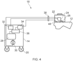
Figure 4 is a schematic view of the electrochemical machining device ofFigure 1 ; and - Figure 5 is a cross-sectional side view of a machining unit of the electrochemical machining device of
Figure 1 . - Referring firstly to
Figure 1 , anelectrochemical machining device 10 for machining asurface 12 of a workpiece is illustrated. - The
electrochemical machining device 10 includes abase unit 14 and a hand-heldmachining unit 16. Thebase unit 14 andmachining unit 16 are connected via anumbilical cord 18 through which thebase unit 14 is able to supply power and electrolyte to themachining unit 16. - Connection of the
machining unit 16 to thebase unit 14 via the flexibleumbilical cord 18 enables the hand-heldmachining unit 16 to be moved independently of thebase unit 14. Put another way, themachining unit 16 is provided as a portable unit. This arrangement enables thedevice 10 to be to be used in-situ either as part of a mobile device or as part of a fixed position machining system. - In the illustrated arrangement, the
base unit 14 is shown as aportable base unit 14. Thebase unit 14 is mounted onwheels 20 so as to be moveable about a space (i.e. moveable to be close to a surface to be machined). In alternative arrangements, it will be appreciated that thebase unit 14 may not be portable, and only themachining unit 16 may be transported/moved to asurface 12 to be machined. - As is illustrated in
Figure 1 , themachining unit 16 is held against asurface 12 of a workpiece to machine saidsurface 12. Themachining unit 16 ofFigure 1 is configured such that it is able to be moved over asurface 12 of a workpiece by an operator without having to remove and the re-attach said machining unit. This arrangement enables machining to be carried out continuously over thesurface 12. Although not illustrated, themachining unit 16 may include one or more contact points arranged to engage thesurface 12 and be moveable/slideable thereover. - Referring to
Figure 2 , themachining unit 16 is moveable with respect to the base unit (not shown) and is operated by arobotic arm 52. Themachining unit 16 is connected to the base unit via theumbilical cord 18. It will be appreciated that therobotic arm 52 may be provided as a part of an automated production line. - The
machining unit 16 ofFigure 2 is configured such that it is able to be moved over asurface 12 of a workpiece byrobotic arm 52 without having to remove and the re-attach said machining unit. This arrangement enables machining to be carried out continuously over thesurface 12. Although not illustrated, themachining unit 16 may include one or more contact points arranged to engage thesurface 12 and be moveable/slideable thereover. - Referring to
Figure 3 , themachining unit 16 is positioned on asurface 12 of a workpiece. Themachining unit 16 is connected to the base unit (not shown) via theumbilical cord 18. Themachining unit 16 is configured to be driven over thesurface 12. - In order to drive the
machining unit 16 over thesurface 12, a drive arrangement (not shown) is provided. The drive arrangement is configured to move themachining unit 16 over thesurface 12. Provision of the drive arrangement enables themachining unit 16 to move over thesurface 12 without requiring it to be manually moved an operator. In one arrangement, theelectrochemical machining device 10 may be provided with a control system configured to control movement of themachining unit 16 via the drive arrangement. In the illustrated arrangement, movement of themachining unit 16 over thesurface 12 is being controlled by a control system provided in the base unit. It will be appreciated that the drive arrangement may be provided as one or more wheels for propelling themachining unit 16 over thesurface 12, or that any other suitable alternaitve drive arrangement may be used. - The
machining unit 16 ofFigure 3 is configured such that it is able to be moved (i.e. driven) over asurface 12 of a workpiece without having to remove and the re-attach said machining unit. This arrangement enables machining to be carried out continuously over thesurface 12. Although not illustrated, themachining unit 16 may include one or more contact points arranged to engage thesurface 12 and be moveable/slideable thereover. - The
portable machining unit 16 illustrated inFigures 1 ,2 and3 is able to be easily moved, e.g. independently of thebase unit 14, between different surfaces or to different positons on a single surface so as to carry out machining processes. It will be appreciated that themachining unit 16 is designed to be operated either manually (as illustrated inFigure 1 ) or as part of an automated process (as illustrated inFigure 2 ) or to be operated remotely (as illustrated inFigure 3 ). - The
machining unit 16 is configured to modify the topography of asurface 12 through an electrochemical process. Providing a hand-heldmachining unit 16 that is able to machine asurface 12 in-situ, enables thesurface 12 to be modified without requiring it to be removed from a machine production line and loaded onto a separate machining device. - Referring now to
Figure 4 , themachining unit 16 is shown positioned on thesurface 12 of a workpiece. - The
machining unit 16 includes ahousing 22. Anozzle 24 is positioned within thehousing 22, and thenozzle 24 is configured to dispense anelectrolyte jet 26 towards asurface 12 of a workpiece. Thehousing 22 is configured to define an enclosed workspace when positioned against asurface 12 of a workpiece. - It will be appreciated that the
nozzle 24 may be removably mounted within themachining unit housing 22 to allow for different nozzles to be used for different machining operations. - In the embodiment, the electrolyte is a water-based electrolyte. The electrolyte is provided as a water-salt solution, for example a water based solution comprising one or more of sodium nitrate, sodium chloride, sodium iodide etc. It will be appreciated that any suitable electrolyte may be used, such as a substantially water free ionic solvent.
- The
electrochemical machining device 10 is configured to apply a charge to thenozzle 24 and thesurface 12. In this way, thenozzle 24 and thesurface 12 for first and second electrodes of an electrolytic cell. In alternative arrangements, themachining unit 16 may include an additional electrode, separate from the nozzle, and the electrochemical machining device may be configured to apply a charge to the additional electrode and thesurface 12. - Material removal and deposition is achieved by an electrolyte being supplied through the
nozzle 24 and jetted towards thesurface 12. An electrical potential is applied between thenozzle 24 and thesurface 12 resulting in either anodic dissolution of thesurface 12, or deposition onto thesurface 12. - In a first mode of operation, a negative charge is applied to the
nozzle 24 and a positive charge is applied to thesurface 12. In this first mode of operation, thedevice 10 etches away at thesurface 12 so as to modify the topography thereof. In a second mode of operation, a positive charge is applied to thenozzle 24 and a negative charge is applied to thesurface 12. In this second mode of operation, material (e.g. such as silica particles or additive coatings to allow functionalisation of the surface) are able to be deposited onto thesurface 12, which modifies the surface topography thereof. - The
nozzle 24 is arranged within thehousing 22 so as to be spaced apart from thesurface 12, in use. The spacing between theelectrode 24 and the workpiece surface 12 (i.e. the inter-electrode gap) affects the processing of thesurface 12. Thenozzle 24 is moveable within thehousing 22. Thenozzle 24 is moveable within thehousing 22 such that the spacing between thenozzle 24 and thesurface 12 can be adjusted to suit a particular machining operation. - In order to be able to apply a charge to the
nozzle 24 and thesurface 12, thebase unit 14 includes apower source 32 for supplying power to themachining unit 16 via theumbilical cord 18. It will be appreciated that in order to supply power to themachining unit 16, thepower source 32 may include one or more batteries or may be connectable to an external power source. - The
base unit 14 includes anelectrolyte reservoir 28 for supplying electrolyte to thenozzle 24. Providing the device 10 (i.e. the base unit 14) with anelectrolyte reservoir 28 enables thedevice 10 to be utilised away from an electrolyte source. In this way, the portability of thedevice 10 is improved. Thebase unit 14 also includes afluid pump 30 for pumping fluid to thenozzle 24 of themachining unit 16 - In order to remove the used electrolyte from the workspace, the
machining unit 16 includes aretrieval arrangement 48 for retrieving the used electrolyte. Theretrieval arrangement 48 is arranged to return the retrieved electrolyte to theelectrolyte reservoir 28 via theumbilical cord 18. Theretrieval arrangement 48 is provided in the form of one or more suction pumps (not shown), e.g. vacuum pumps. The one or more suction pumps are disposed within thehousing 22. - Whilst the
housing 22 has been described as forming an enclosed workspace when positioned against asurface 12 of a workpiece, it will be understood that said enclosed workspace will comprise one or more apertures 50 for one or more suction pumps therein. The suction pumps are configured to produce an air stream to draw in the retrieved electrolyte, and the air streams substantially cover the apertures such that the workspace is substantially enclosed (but the housing walls and the air streams of the suction pumps). In alternative arrangements, the suction pumps 50 may be provided on an exterior of thehousing 22 or may be provided separate to thehousing 22. - The electrolyte retrieved from the workspace can be re-used for a subsequent machining process. Prior to re-entering the
electrolyte reservoir 28, the retrieved electrolyte passes through afilter 34 to remove the machined debris from the electrolyte. In this way, thebase unit 14, which is separate from themachining unit 16, supplies, retrieves and refines the electrolyte. - The
electrochemical machining device 10 is also provided with anelectrolyte monitoring system 36 for monitoring the electrolyte. This arrangement allows an operator to monitor the quality of the electrolyte with thedevice 10. In the arrangement shown, theelectrolyte monitoring system 36 is provided between thefilter 34 and thereservoir 28. In order to characterise the electrolyte, themonitoring system 36 includes one or more of a pH sensor, a temperature sensor, an electrical conductivity sensor, and a particulate matter for determining the debris contained in the electrolyte within the electrolyte reservoir. - As discussed above, the
umbilical cord 18 provides themachining unit 16 with power, electrolyte and also provides a flow path for aretrieval arrangement 48. Theumbilical cord 18 connects thebase unit 14 and themachining unit 16 via a quick connect/disconnect coupling 38. The quick connect/disconnect coupling 38 is configured such that, upon disconnection, the supply of power, electrolyte and suction is stopped. - Referring to Figure 5, the
machining unit 16 is illustrated in more detail. - The
machining unit 16 is provided with a contact electrode 44 configured and arranged to contact at least a portion of thesurface 12, in use. Through this contact electrode 44, themachining unit 16 is able to apply to charge to thesurface 12. In this way, thesurface 12 and thenozzle 24 are able to form an electrolytic cell, to enable the electrochemical machining to occur. In the illustrated arrangement, the contact electrode 44 is provided within thehousing 22. - As has been discussed above, the
machining unit 16 is configured so as to be moveable over thesurface 12. The housing includes one or more contact points arranged to engage thesurface 12 and be moveable/slideable thereover. - The one or more contact points may be formed from a malleable or deformable material so as to minimise damage to the
surface 12 as themachining unit 16 is moved thereover. In the illustrated arrangement, the one or more contact points are formed from a conductive material. Providing the contact point 44 as a conductive material enables the contact points to form the contact electrode. The one or more contact points may be formed from a malleable or deformable metal, such as copper, aluminium, aluminium alloys, gold, silver platinum etc. - In alternative arrangements, the contact electrode may be provided separately from the contact points. In such arrangements, the contact electrode may be provided in the form of an elongate conductive member, e.g. a rod, arranged to contact a surface of a workpiece, in use. The elongate member or rod may include a contact member (e.g. a ball) rotatably mounted at a distal end thereof that is arranged so as to contact the 12 surface of a workpiece. It will be understood that the contact electrode may be formed from a conductive material, such as a malleable or deformable metal e.g. copper, aluminium, aluminium alloys, gold, silver platinum etc.
- The
housing 22 is configured to define the spacing between thenozzle 24 and thesurface 12. Put another way, the one or more contact points 44 are arranged within thehousing 22 to define the spacing between thenozzle 24 and thesurface 12. This arrangement ensures that a spacing will be provided between thenozzle 24 and thesurface 12 when an operator places thehousing 22 onto saidsurface 12. - The
nozzle 24 is mounted so as to be moveable within thehousing 22. In the illustrated arrangement, thenozzle 24 is moveable across a plane substantially parallel with thesurface 12. Put another way, the nozzle is moveable laterally over asurface 12 of a workpiece. In this way, theelectrolyte jet 26 is able to be traversed over thesurface 12. In order to achieve this two axes of movement, thenozzle 24 is mounted to an actuator 40. In the arrangement shown, the actuator is a single plane bi-direction linear actuator 40, controlling the traversing of the jet over thesurface 12. Although not illustrated, thenozzle 24 is pivotably mounted within thehousing 24. In this way, the angle of theelectrolyte jet 26 relative to thesurface 12 is able to be changed to suit the machining operation. - The
nozzle 24 is moveable within thehousing 22 for adjusting the spacing between thenozzle 24 and thesurface 12. In the arrangement shown, thenozzle 24 is mounted to the actuator 40 via a screw thread 42. This arrangement enables thenozzle 24 to be moved in a direction substantially perpendicular to the surface 12 (i.e. in a direction towards and away from the surface 12). - The
base unit 14 is provided with a control system (not shown) that is configured to determine the spacing between thenozzle 24 and thesurface 12 during a machining operation. Following this spacing determination, the control system is configured to adjust the position of thenozzle 24 so as to maintain a substantially constant spacing between thenozzle 24 and thesurface 12, during a machining operation. - As discussed above, the spacing between the
nozzle 24 and thesurface 12 affects the resulting topography of thesurface 12 after the machining process. Providing an arrangement that is able to maintain a constant spacing enables thesurface 12 to be uniformly machined. This is particularly advantageous when thesurface 12 is non-planar. In this arrangement, the spacing is determined by calculating an electrical resistance between thenozzle 24 and thesurface 12, during a machining operation. The resistance is calculated from the current and the voltage within the electrolytic cell. It will be appreciated that in alternative embodiments, alternative arrangements for determining this spacing may be used, such as by using lasers, ultrasonic sensors or the like. - The
machining unit 16 includes a gas outlet 46 within thehousing 22. The gas outlet 46 is configured to dispense a jet a compressed gas (e.g. air) for focusing theelectrolyte jet 26. In the arrangement shown, the gas outlet 46 is configured to dispense a gas stream which encircles theelectrolyte jet 26, in use. Providing a gas stream encircling (i.e. providing a gas shroud around) theelectrolyte jet 26 focuses the jet to enhance selectivity of the machining. In some arrangements, the gas stream may only partially surround theelectrolyte jet 26. - Although not illustrated, the
machining unit 16 may be provided with an attachment arrangement for attaching themachining unit 16 onto thesurface 12, in use. The attachment arrangement may be configured to retain themachining unit 16 on thesurface 12, whilst allowing the machining unit to be moveable along saidsurface 12. One example of such an attachment arrangement may be an attachment suction arrangement. Such an attachment suction arrangement may be provided in the form of one or more suction pumps in or on thehousing 22. - Although not illustrated, in alternative arrangements the
machining unit 16 may include first and second nozzles for dispensing an electrolyte jet towards asurface 12 to be machined. This allows a greater degree of control of the surface topography created and optimised cycle times due to exploitation of the dual electrolyte jets. In such arrangements, both the first and second nozzles may be configured to dispense the same electrolyte. Alternatively, thebase unit 14 may include a second electrolyte reservoir, and the two nozzles may be configured for dispensing different electrolytes. - Although the invention has been described above with reference to one or more preferred embodiments, it will be appreciated that various changes or modifications may be made without departing from the scope of the invention as defined in the appended claims.
Claims (15)
- An electrochemical machining device (10) for machining a surface (12) of a workpiece, the electrochemical machining device comprising:a base unit (14); anda portable machining unit (16) comprising a housing (22) for positioning against a surface (12) of a workpiece, a nozzle (24) disposed within the housing (22) and configured to dispense an electrolyte jet (26) towards a surface of a workpiece,wherein the machining unit (16) is connected to the base unit (14) via an umbilical cord (18) for supplying power to the machining unit (16) and for supplying electrolyte to the nozzle (24),wherein the electrochemical machining device (10) is configured to apply a charge to the nozzle (24) and to apply a charge to a surface (12) of a workpiece such that the nozzle (24) and said surface (12) define first and second electrodes of an electrolytic cell, in use, andwherein the nozzle (24) is arranged so as to be spaced apart from a surface (12) of a workpiece, in use.
- An electrochemical machining device (10) according to claim 1, wherein the nozzle (24) is moveable within the housing (22) along a plane substantially parallel with the surface, in use.
- An electrochemical machining device (10) according to claim 1 or claim 2, wherein the nozzle (24) is moveable within the housing (22) such that the spacing between the nozzle (24) and a surface (12) of a workpiece is adjustable, in use.
- An electrochemical machining device (10) according to any preceding claim, wherein the nozzle (24) is pivotable within the housing (22) for changing the angle of the electrolyte jet (26) relative to a surface (12) of a workpiece, in use.
- An electrochemical machining device (10) according to any preceding claim, wherein the housing (22) is configured to engage a surface (12) of a workpiece so as to be moveable over said surface, in use.
- An electrochemical machining device (10) according to any preceding claim, wherein the machining unit (16) comprises a contact electrode (44) configured an arranged to contact a surface (12) of a workpiece, in use, and to apply a current thereto.
- An electrochemical machining device (10) according to any preceding claim, wherein the housing (22) comprise one or more contact points arranged to engage a surface of a workpiece, in use, and wherein the one or more contact points are formed from a malleable and/or deformable material, optionally wherein the one or more contact points are formed from a conductive material such that they are a contact electrode for configured an arranged to contact a surface (12) of a workpiece, in use, and to apply a current thereto.
- An electrochemical machining device (10) according to any preceding claim, comprising a control system configured to determine the spacing between the nozzle (24) and a surface (12) of a workpiece, in use, optionally wherein the control system is configured so as to maintain a substantially constant spacing between the nozzle (24) and a surface (12) of a workpiece, during a machining operation, optionally wherein the control system determines the spacing between the nozzle (24) and a surface (12) of a workpiece by calculating an electrical resistance therebetween.
- An electrochemical machining device (10) according to any preceding claim, wherein the housing (22) is configured to define an enclosed workspace when positioned against a surface (12 of a workpiece.
- An electrochemical machining device (10) according to any preceding claim, wherein the base unit (14) comprises an electrolyte reservoir (28) for supplying electrolyte to the nozzle (24), and wherein the machining unit (16) comprises a retrieval arrangement for retrieving used electrolyte, optionally wherein the retrieval arrangement is configured to return the retrieved electrolyte to the electrolyte reservoir (28), optionally wherein the retrieved electrolyte is filtered prior to re-entering the electrolyte reservoir (28).
- An electrochemical machining device (10) according to any preceding claim, wherein the machining unit (16) comprises an attachment arrangement for attaching the machining unit (16) onto a surface (12) of a workpiece, in use, optionally, wherein the attachment arrangement is configured to allow the machining unit (16) to move with respect to a surface (12) of a workpiece, in use, whilst remaining attached thereto.
- An electrochemical machining device (10) according to any preceding claim, comprising an electrolyte monitoring system (36) for monitoring the electrolyte in the electrolyte reservoir (28), optionally wherein the electrolyte monitoring system (36) comprises one or more of: a pH sensor; a temperature sensor; an electrical conductivity sensor; and/or a particulate matter for determining the debris contained in the electrolyte within the electrolyte reservoir.
- An electrochemical machining device (10) according to any preceding claim, wherein the machining unit (16) comprises a drive arrangement configured to move the machining unit (16) over a surface (12) of a workpiece, in use.
- An electrochemical machining device (10) according to any preceding claim, wherein the umbilical cord (18) is connected to either the base unit (14) and/or the machining unit (16) via a quick connect/disconnect coupling configured such that, upon disconnection, supply of power and electrolyte is stopped.
- An electrochemical machining device (10) according to any preceding claim, wherein the machining unit (16) comprises a gas outlet (46) arranged to dispense a gas stream which encircles the electrolyte jet (26), in use.
Applications Claiming Priority (2)
| Application Number | Priority Date | Filing Date | Title |
|---|---|---|---|
| GBGB1907798.1A GB201907798D0 (en) | 2019-05-31 | 2019-05-31 | An electrochemical machining device |
| PCT/GB2020/051294 WO2020240188A1 (en) | 2019-05-31 | 2020-05-28 | An electrochemical machining device |
Publications (3)
| Publication Number | Publication Date |
|---|---|
| EP3976862A1 EP3976862A1 (en) | 2022-04-06 |
| EP3976862C0 EP3976862C0 (en) | 2024-07-17 |
| EP3976862B1 true EP3976862B1 (en) | 2024-07-17 |
Family
ID=67385988
Family Applications (1)
| Application Number | Title | Priority Date | Filing Date |
|---|---|---|---|
| EP20735651.0A Active EP3976862B1 (en) | 2019-05-31 | 2020-05-28 | An electrochemical machining device |
Country Status (3)
| Country | Link |
|---|---|
| EP (1) | EP3976862B1 (en) |
| GB (1) | GB201907798D0 (en) |
| WO (1) | WO2020240188A1 (en) |
Family Cites Families (4)
| Publication number | Priority date | Publication date | Assignee | Title |
|---|---|---|---|---|
| US4882019A (en) * | 1988-11-21 | 1989-11-21 | Lewy Michael M | Apparatus and method for polishing a plumbing or electrical fixture |
| US5002643A (en) * | 1990-01-05 | 1991-03-26 | Andrews James D | Electrode with outside flow of electrolyte for electrochemical machining and method |
| US20100072077A1 (en) * | 2008-09-23 | 2010-03-25 | Rohrbeck Michael R | Electrolytic deburring apparatus and method |
| US20160361770A1 (en) * | 2011-01-12 | 2016-12-15 | Perfect Point Edm Corporation | Dynamic adaptive flushing for workpiece erosion |
-
2019
- 2019-05-31 GB GBGB1907798.1A patent/GB201907798D0/en not_active Ceased
-
2020
- 2020-05-28 WO PCT/GB2020/051294 patent/WO2020240188A1/en not_active Ceased
- 2020-05-28 EP EP20735651.0A patent/EP3976862B1/en active Active
Also Published As
| Publication number | Publication date |
|---|---|
| WO2020240188A1 (en) | 2020-12-03 |
| EP3976862A1 (en) | 2022-04-06 |
| GB201907798D0 (en) | 2019-07-17 |
| EP3976862C0 (en) | 2024-07-17 |
Similar Documents
| Publication | Publication Date | Title |
|---|---|---|
| US9914238B2 (en) | Apparatus for generating a pulsating pressurized fluid jet | |
| EP3461578B1 (en) | Electrical discharge machining | |
| JP5766493B2 (en) | Abrasive water jet processing equipment | |
| US7394040B2 (en) | Electromachining process and apparatus | |
| WO2018006434A1 (en) | Shot blasting and electrodeposition manufacturing method and apparatus for three-dimensional surface | |
| CN101462243A (en) | Grinding machine with a device for conditioning a grinding wheel and a method of conditioning a grinding wheel | |
| CN119016815B (en) | Electrolytic mechanical combined polishing processing electrode for recasting layer of straight surface component and electrolytic processing method thereof | |
| US4559115A (en) | Method of and apparatus for machining ceramic materials | |
| CN110340472A (en) | A kind of metalwork fine structure abradant jet electrical-chemistry method System and method for | |
| RU2489236C2 (en) | Method of electro-abrasive machining by current-conducting wheel | |
| US20250121445A1 (en) | Device and Method for Plasma-Electrolytic Machining of the Electrically Conductive Surface of a Workpiece by Electrolyte Jets | |
| EP3976862A1 (en) | An electrochemical machining device | |
| US20100072077A1 (en) | Electrolytic deburring apparatus and method | |
| JP2016112644A (en) | Electric discharge machine with cleaning system by robot | |
| JP2000141134A (en) | Method and device for machining workpiece three- dimensionally through electric discharge machining or electrolytic grinding | |
| US20170368626A1 (en) | Electrochemical Removal Of Material From A Workpiece | |
| CN106670603B (en) | A self-repairing wire electrode electric spark cutting device and method | |
| US8070933B2 (en) | Electrolytic microfinishing of metallic workpieces | |
| JP2008062328A (en) | Combined machining equipment capable of water jet machining and wire electrical discharge machining | |
| JP2001062632A (en) | Metal working method and equipment | |
| RU2622075C1 (en) | Method of electrochemical dimensional processing by a rotating electrode with the excentrice of the working surface | |
| CN218190557U (en) | Adjustable nozzle of paint spraying robot arm | |
| RU2824368C1 (en) | Robotic device for piercing and processing of holes in article | |
| US20250269457A1 (en) | Esd welding apparatus and method | |
| JP3058308B2 (en) | Wire cut electric discharge machining method |
Legal Events
| Date | Code | Title | Description |
|---|---|---|---|
| STAA | Information on the status of an ep patent application or granted ep patent |
Free format text: STATUS: UNKNOWN |
|
| STAA | Information on the status of an ep patent application or granted ep patent |
Free format text: STATUS: THE INTERNATIONAL PUBLICATION HAS BEEN MADE |
|
| PUAI | Public reference made under article 153(3) epc to a published international application that has entered the european phase |
Free format text: ORIGINAL CODE: 0009012 |
|
| STAA | Information on the status of an ep patent application or granted ep patent |
Free format text: STATUS: REQUEST FOR EXAMINATION WAS MADE |
|
| 17P | Request for examination filed |
Effective date: 20211209 |
|
| AK | Designated contracting states |
Kind code of ref document: A1 Designated state(s): AL AT BE BG CH CY CZ DE DK EE ES FI FR GB GR HR HU IE IS IT LI LT LU LV MC MK MT NL NO PL PT RO RS SE SI SK SM TR |
|
| DAV | Request for validation of the european patent (deleted) | ||
| DAX | Request for extension of the european patent (deleted) | ||
| STAA | Information on the status of an ep patent application or granted ep patent |
Free format text: STATUS: EXAMINATION IS IN PROGRESS |
|
| 17Q | First examination report despatched |
Effective date: 20230130 |
|
| RAP1 | Party data changed (applicant data changed or rights of an application transferred) |
Owner name: TEXTURE JET LTD |
|
| REG | Reference to a national code |
Ref country code: DE Ref legal event code: R079 Free format text: PREVIOUS MAIN CLASS: C25F0007000000 Ipc: B23H0003000000 Ref document number: 602020034124 Country of ref document: DE |
|
| RIC1 | Information provided on ipc code assigned before grant |
Ipc: C25F 7/00 20060101ALI20240207BHEP Ipc: B23H 3/00 20060101AFI20240207BHEP |
|
| GRAP | Despatch of communication of intention to grant a patent |
Free format text: ORIGINAL CODE: EPIDOSNIGR1 |
|
| STAA | Information on the status of an ep patent application or granted ep patent |
Free format text: STATUS: GRANT OF PATENT IS INTENDED |
|
| INTG | Intention to grant announced |
Effective date: 20240322 |
|
| GRAS | Grant fee paid |
Free format text: ORIGINAL CODE: EPIDOSNIGR3 |
|
| GRAA | (expected) grant |
Free format text: ORIGINAL CODE: 0009210 |
|
| STAA | Information on the status of an ep patent application or granted ep patent |
Free format text: STATUS: THE PATENT HAS BEEN GRANTED |
|
| AK | Designated contracting states |
Kind code of ref document: B1 Designated state(s): AL AT BE BG CH CY CZ DE DK EE ES FI FR GB GR HR HU IE IS IT LI LT LU LV MC MK MT NL NO PL PT RO RS SE SI SK SM TR |
|
| REG | Reference to a national code |
Ref country code: CH Ref legal event code: EP |
|
| REG | Reference to a national code |
Ref country code: DE Ref legal event code: R096 Ref document number: 602020034124 Country of ref document: DE |
|
| REG | Reference to a national code |
Ref country code: IE Ref legal event code: FG4D |
|
| U01 | Request for unitary effect filed |
Effective date: 20240813 |
|
| U07 | Unitary effect registered |
Designated state(s): AT BE BG DE DK EE FI FR IT LT LU LV MT NL PT RO SE SI Effective date: 20240902 |
|
| PG25 | Lapsed in a contracting state [announced via postgrant information from national office to epo] |
Ref country code: NO Free format text: LAPSE BECAUSE OF FAILURE TO SUBMIT A TRANSLATION OF THE DESCRIPTION OR TO PAY THE FEE WITHIN THE PRESCRIBED TIME-LIMIT Effective date: 20241017 |
|
| PG25 | Lapsed in a contracting state [announced via postgrant information from national office to epo] |
Ref country code: PL Free format text: LAPSE BECAUSE OF FAILURE TO SUBMIT A TRANSLATION OF THE DESCRIPTION OR TO PAY THE FEE WITHIN THE PRESCRIBED TIME-LIMIT Effective date: 20240717 Ref country code: GR Free format text: LAPSE BECAUSE OF FAILURE TO SUBMIT A TRANSLATION OF THE DESCRIPTION OR TO PAY THE FEE WITHIN THE PRESCRIBED TIME-LIMIT Effective date: 20241018 |
|
| PG25 | Lapsed in a contracting state [announced via postgrant information from national office to epo] |
Ref country code: IS Free format text: LAPSE BECAUSE OF FAILURE TO SUBMIT A TRANSLATION OF THE DESCRIPTION OR TO PAY THE FEE WITHIN THE PRESCRIBED TIME-LIMIT Effective date: 20241117 |
|
| PG25 | Lapsed in a contracting state [announced via postgrant information from national office to epo] |
Ref country code: HR Free format text: LAPSE BECAUSE OF FAILURE TO SUBMIT A TRANSLATION OF THE DESCRIPTION OR TO PAY THE FEE WITHIN THE PRESCRIBED TIME-LIMIT Effective date: 20240717 |
|
| PG25 | Lapsed in a contracting state [announced via postgrant information from national office to epo] |
Ref country code: RS Free format text: LAPSE BECAUSE OF FAILURE TO SUBMIT A TRANSLATION OF THE DESCRIPTION OR TO PAY THE FEE WITHIN THE PRESCRIBED TIME-LIMIT Effective date: 20241017 Ref country code: ES Free format text: LAPSE BECAUSE OF FAILURE TO SUBMIT A TRANSLATION OF THE DESCRIPTION OR TO PAY THE FEE WITHIN THE PRESCRIBED TIME-LIMIT Effective date: 20240717 |
|
| PG25 | Lapsed in a contracting state [announced via postgrant information from national office to epo] |
Ref country code: RS Free format text: LAPSE BECAUSE OF FAILURE TO SUBMIT A TRANSLATION OF THE DESCRIPTION OR TO PAY THE FEE WITHIN THE PRESCRIBED TIME-LIMIT Effective date: 20241017 Ref country code: PL Free format text: LAPSE BECAUSE OF FAILURE TO SUBMIT A TRANSLATION OF THE DESCRIPTION OR TO PAY THE FEE WITHIN THE PRESCRIBED TIME-LIMIT Effective date: 20240717 Ref country code: NO Free format text: LAPSE BECAUSE OF FAILURE TO SUBMIT A TRANSLATION OF THE DESCRIPTION OR TO PAY THE FEE WITHIN THE PRESCRIBED TIME-LIMIT Effective date: 20241017 Ref country code: IS Free format text: LAPSE BECAUSE OF FAILURE TO SUBMIT A TRANSLATION OF THE DESCRIPTION OR TO PAY THE FEE WITHIN THE PRESCRIBED TIME-LIMIT Effective date: 20241117 Ref country code: HR Free format text: LAPSE BECAUSE OF FAILURE TO SUBMIT A TRANSLATION OF THE DESCRIPTION OR TO PAY THE FEE WITHIN THE PRESCRIBED TIME-LIMIT Effective date: 20240717 Ref country code: GR Free format text: LAPSE BECAUSE OF FAILURE TO SUBMIT A TRANSLATION OF THE DESCRIPTION OR TO PAY THE FEE WITHIN THE PRESCRIBED TIME-LIMIT Effective date: 20241018 Ref country code: ES Free format text: LAPSE BECAUSE OF FAILURE TO SUBMIT A TRANSLATION OF THE DESCRIPTION OR TO PAY THE FEE WITHIN THE PRESCRIBED TIME-LIMIT Effective date: 20240717 |
|
| PG25 | Lapsed in a contracting state [announced via postgrant information from national office to epo] |
Ref country code: SM Free format text: LAPSE BECAUSE OF FAILURE TO SUBMIT A TRANSLATION OF THE DESCRIPTION OR TO PAY THE FEE WITHIN THE PRESCRIBED TIME-LIMIT Effective date: 20240717 |
|
| PG25 | Lapsed in a contracting state [announced via postgrant information from national office to epo] |
Ref country code: CZ Free format text: LAPSE BECAUSE OF FAILURE TO SUBMIT A TRANSLATION OF THE DESCRIPTION OR TO PAY THE FEE WITHIN THE PRESCRIBED TIME-LIMIT Effective date: 20240717 |
|
| PG25 | Lapsed in a contracting state [announced via postgrant information from national office to epo] |
Ref country code: SK Free format text: LAPSE BECAUSE OF FAILURE TO SUBMIT A TRANSLATION OF THE DESCRIPTION OR TO PAY THE FEE WITHIN THE PRESCRIBED TIME-LIMIT Effective date: 20240717 |
|
| PLBE | No opposition filed within time limit |
Free format text: ORIGINAL CODE: 0009261 |
|
| STAA | Information on the status of an ep patent application or granted ep patent |
Free format text: STATUS: NO OPPOSITION FILED WITHIN TIME LIMIT |
|
| 26N | No opposition filed |
Effective date: 20250422 |
|
| U20 | Renewal fee for the european patent with unitary effect paid |
Year of fee payment: 6 Effective date: 20250529 |
|
| PGFP | Annual fee paid to national office [announced via postgrant information from national office to epo] |
Ref country code: CH Payment date: 20250601 Year of fee payment: 6 |
|
| PG25 | Lapsed in a contracting state [announced via postgrant information from national office to epo] |
Ref country code: MC Free format text: LAPSE BECAUSE OF FAILURE TO SUBMIT A TRANSLATION OF THE DESCRIPTION OR TO PAY THE FEE WITHIN THE PRESCRIBED TIME-LIMIT Effective date: 20240717 |
|
| PGFP | Annual fee paid to national office [announced via postgrant information from national office to epo] |
Ref country code: GB Payment date: 20260323 Year of fee payment: 7 |
|
| PG25 | Lapsed in a contracting state [announced via postgrant information from national office to epo] |
Ref country code: IE Free format text: LAPSE BECAUSE OF NON-PAYMENT OF DUE FEES Effective date: 20250528 |