EP3976516B1 - A device and corresponding method for grouping blanks of wrappers of smoking articles - Google Patents
A device and corresponding method for grouping blanks of wrappers of smoking articles Download PDFInfo
- Publication number
- EP3976516B1 EP3976516B1 EP20728562.8A EP20728562A EP3976516B1 EP 3976516 B1 EP3976516 B1 EP 3976516B1 EP 20728562 A EP20728562 A EP 20728562A EP 3976516 B1 EP3976516 B1 EP 3976516B1
- Authority
- EP
- European Patent Office
- Prior art keywords
- blanks
- support
- blank
- collecting space
- group
- Prior art date
- Legal status (The legal status is an assumption and is not a legal conclusion. Google has not performed a legal analysis and makes no representation as to the accuracy of the status listed.)
- Active
Links
Images


Classifications
-
- B—PERFORMING OPERATIONS; TRANSPORTING
- B65—CONVEYING; PACKING; STORING; HANDLING THIN OR FILAMENTARY MATERIAL
- B65H—HANDLING THIN OR FILAMENTARY MATERIAL, e.g. SHEETS, WEBS, CABLES
- B65H31/00—Pile receivers
- B65H31/04—Pile receivers with movable end support arranged to recede as pile accumulates
- B65H31/06—Pile receivers with movable end support arranged to recede as pile accumulates the articles being piled on edge
-
- B—PERFORMING OPERATIONS; TRANSPORTING
- B65—CONVEYING; PACKING; STORING; HANDLING THIN OR FILAMENTARY MATERIAL
- B65B—MACHINES, APPARATUS OR DEVICES FOR, OR METHODS OF, PACKAGING ARTICLES OR MATERIALS; UNPACKING
- B65B19/00—Packaging rod-shaped or tubular articles susceptible to damage by abrasion or pressure, e.g. cigarettes, cigars, macaroni, spaghetti, drinking straws or welding electrodes
- B65B19/02—Packaging cigarettes
- B65B19/22—Wrapping the cigarettes; Packaging the cigarettes in containers formed by folding wrapping material around formers
- B65B19/228—Preparing and feeding blanks
-
- B—PERFORMING OPERATIONS; TRANSPORTING
- B65—CONVEYING; PACKING; STORING; HANDLING THIN OR FILAMENTARY MATERIAL
- B65B—MACHINES, APPARATUS OR DEVICES FOR, OR METHODS OF, PACKAGING ARTICLES OR MATERIALS; UNPACKING
- B65B43/00—Forming, feeding, opening or setting-up containers or receptacles in association with packaging
- B65B43/12—Feeding flexible bags or carton blanks in flat or collapsed state; Feeding flat bags connected to form a series or chain
- B65B43/126—Feeding carton blanks in flat or collapsed state
-
- B—PERFORMING OPERATIONS; TRANSPORTING
- B65—CONVEYING; PACKING; STORING; HANDLING THIN OR FILAMENTARY MATERIAL
- B65B—MACHINES, APPARATUS OR DEVICES FOR, OR METHODS OF, PACKAGING ARTICLES OR MATERIALS; UNPACKING
- B65B43/00—Forming, feeding, opening or setting-up containers or receptacles in association with packaging
- B65B43/12—Feeding flexible bags or carton blanks in flat or collapsed state; Feeding flat bags connected to form a series or chain
- B65B43/14—Feeding individual bags or carton blanks from piles or magazines
- B65B43/145—Feeding carton blanks from piles or magazines
-
- B—PERFORMING OPERATIONS; TRANSPORTING
- B65—CONVEYING; PACKING; STORING; HANDLING THIN OR FILAMENTARY MATERIAL
- B65B—MACHINES, APPARATUS OR DEVICES FOR, OR METHODS OF, PACKAGING ARTICLES OR MATERIALS; UNPACKING
- B65B43/00—Forming, feeding, opening or setting-up containers or receptacles in association with packaging
- B65B43/12—Feeding flexible bags or carton blanks in flat or collapsed state; Feeding flat bags connected to form a series or chain
- B65B43/14—Feeding individual bags or carton blanks from piles or magazines
- B65B43/16—Feeding individual bags or carton blanks from piles or magazines by grippers
- B65B43/18—Feeding individual bags or carton blanks from piles or magazines by grippers by suction-operated grippers
- B65B43/185—Feeding individual bags or carton blanks from piles or magazines by grippers by suction-operated grippers specially adapted for carton blanks
-
- B—PERFORMING OPERATIONS; TRANSPORTING
- B65—CONVEYING; PACKING; STORING; HANDLING THIN OR FILAMENTARY MATERIAL
- B65H—HANDLING THIN OR FILAMENTARY MATERIAL, e.g. SHEETS, WEBS, CABLES
- B65H31/00—Pile receivers
- B65H31/30—Arrangements for removing completed piles
- B65H31/3054—Arrangements for removing completed piles by moving the surface supporting the lowermost article of the pile, e.g. by using belts or rollers
- B65H31/3063—Arrangements for removing completed piles by moving the surface supporting the lowermost article of the pile, e.g. by using belts or rollers by special supports like carriages, containers, trays, compartments, plates or bars, e.g. moved in a closed loop
-
- B—PERFORMING OPERATIONS; TRANSPORTING
- B65—CONVEYING; PACKING; STORING; HANDLING THIN OR FILAMENTARY MATERIAL
- B65H—HANDLING THIN OR FILAMENTARY MATERIAL, e.g. SHEETS, WEBS, CABLES
- B65H33/00—Forming counted batches in delivery pile or stream of articles
- B65H33/16—Forming counted batches in delivery pile or stream of articles by depositing articles in batches on moving supports
-
- B—PERFORMING OPERATIONS; TRANSPORTING
- B65—CONVEYING; PACKING; STORING; HANDLING THIN OR FILAMENTARY MATERIAL
- B65F—GATHERING OR REMOVAL OF DOMESTIC OR LIKE REFUSE
- B65F1/00—Refuse receptacles; Accessories therefor
- B65F1/02—Refuse receptacles; Accessories therefor without removable inserts
-
- B—PERFORMING OPERATIONS; TRANSPORTING
- B65—CONVEYING; PACKING; STORING; HANDLING THIN OR FILAMENTARY MATERIAL
- B65H—HANDLING THIN OR FILAMENTARY MATERIAL, e.g. SHEETS, WEBS, CABLES
- B65H2301/00—Handling processes for sheets or webs
- B65H2301/40—Type of handling process
- B65H2301/42—Piling, depiling, handling piles
- B65H2301/422—Handling piles, sets or stacks of articles
- B65H2301/4225—Handling piles, sets or stacks of articles in or on special supports
- B65H2301/42252—Vehicles, e.g. carriage, truck
-
- B—PERFORMING OPERATIONS; TRANSPORTING
- B65—CONVEYING; PACKING; STORING; HANDLING THIN OR FILAMENTARY MATERIAL
- B65H—HANDLING THIN OR FILAMENTARY MATERIAL, e.g. SHEETS, WEBS, CABLES
- B65H2301/00—Handling processes for sheets or webs
- B65H2301/40—Type of handling process
- B65H2301/42—Piling, depiling, handling piles
- B65H2301/422—Handling piles, sets or stacks of articles
- B65H2301/4225—Handling piles, sets or stacks of articles in or on special supports
- B65H2301/42254—Boxes; Cassettes; Containers
- B65H2301/422548—Boxes; Cassettes; Containers filling or loading process
-
- B—PERFORMING OPERATIONS; TRANSPORTING
- B65—CONVEYING; PACKING; STORING; HANDLING THIN OR FILAMENTARY MATERIAL
- B65H—HANDLING THIN OR FILAMENTARY MATERIAL, e.g. SHEETS, WEBS, CABLES
- B65H2404/00—Parts for transporting or guiding the handled material
- B65H2404/20—Belts
- B65H2404/23—Belts with auxiliary handling means
- B65H2404/232—Blade, plate, finger
- B65H2404/2321—Blade, plate, finger on two opposite belts or set of belts, i.e. having active handling section cooperating with and facing to each other
-
- B—PERFORMING OPERATIONS; TRANSPORTING
- B65—CONVEYING; PACKING; STORING; HANDLING THIN OR FILAMENTARY MATERIAL
- B65H—HANDLING THIN OR FILAMENTARY MATERIAL, e.g. SHEETS, WEBS, CABLES
- B65H2404/00—Parts for transporting or guiding the handled material
- B65H2404/20—Belts
- B65H2404/26—Particular arrangement of belt, or belts
- B65H2404/267—Arrangement of belt(s) in edge contact with handled material
-
- B—PERFORMING OPERATIONS; TRANSPORTING
- B65—CONVEYING; PACKING; STORING; HANDLING THIN OR FILAMENTARY MATERIAL
- B65H—HANDLING THIN OR FILAMENTARY MATERIAL, e.g. SHEETS, WEBS, CABLES
- B65H2701/00—Handled material; Storage means
- B65H2701/10—Handled articles or webs
- B65H2701/17—Nature of material
- B65H2701/176—Cardboard
- B65H2701/1764—Cut-out, single-layer, e.g. flat blanks for boxes
-
- B—PERFORMING OPERATIONS; TRANSPORTING
- B65—CONVEYING; PACKING; STORING; HANDLING THIN OR FILAMENTARY MATERIAL
- B65H—HANDLING THIN OR FILAMENTARY MATERIAL, e.g. SHEETS, WEBS, CABLES
- B65H2801/00—Application field
- B65H2801/03—Image reproduction devices
- B65H2801/21—Industrial-size printers, e.g. rotary printing press
-
- B—PERFORMING OPERATIONS; TRANSPORTING
- B65—CONVEYING; PACKING; STORING; HANDLING THIN OR FILAMENTARY MATERIAL
- B65H—HANDLING THIN OR FILAMENTARY MATERIAL, e.g. SHEETS, WEBS, CABLES
- B65H2801/00—Application field
- B65H2801/24—Post -processing devices
- B65H2801/31—Devices located downstream of industrial printers
Definitions
- the present invention relates to a device for grouping blanks of smoking-article wrappers, coming one after another from a unit for treating said blanks, according to claim 1.
- This patent describes a device for grouping blanks in an ordered group, after they have undergone treatment.
- This known device comprises a rotatable drum provided with a plurality of radial hoppers which are movable, by rotating the drum, between a position for receiving the single blanks and a delivery position for the reconstituted group of blanks.
- the known device in question also comprises an inclined plane arranged to overturn the individual blanks directed towards one of the hoppers of the drum so that they are arranged parallel to the bottom of the hopper and are deposited one on top of the other to form a pile of blanks.
- US 2013/0004285 A1 and US 5,447,262 A disclose each a device for zig-zag folding of a web.
- US 5,233,814 A discloses a device being movable between a position of loading letters and a position of delivery of a group of letters.
- the present invention has the object of providing an improved grouping device with respect to the known device indicated, in particular from the point of view of the operating mode and the speed of forming the pile of blanks.
- the device described herein performs the function of grouping blanks of smoking-article wrappers which come out in succession from a unit for treating these blanks.
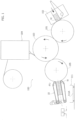
- Figure 1 illustrates an example of a treatment machine for blanks W, which, in particular, carries out a labeling process.
- the illustrated machine indicated as a whole by reference 100, comprises a unit 102 for feeding the blanks W, a labeling unit 104 and a device 10 made according to the disclosures provided here.
- the machine 100 also includes drums 101, 103 and 105 for transporting the blanks from the feeding unit 102 to the labeling unit 104, and from this to the grouping device 10.
- the feeding unit 102 is designed to receive an ordered group of blanks and feed them in succession to the drum 101.
- Each blank W is constituted by a sheet, usually made of paper or cardboard, which is in a completely extended condition, so as to present a planar conformation.
- the blanks that are received by the unit 102 are arranged in an orderly manner so as to form a bundle or pile of blanks. In other words, they are in mutual contact at their respective opposite faces, and have the same orientation with respect to an axis perpendicular to their lying plane.
- Figure 7 illustrates, by way of example, a blank W of a cigarette packet, which must be subjected to the labeling process carried out by the machine 100 of Figure 1 .
- This blank has a given contour and predefined folding lines, so that it can be formed into the final wrapper simply by folding its various portions and their mutual connection (usually by means of glue).
- This figure illustrates an adhesive label T, which is applied on the blank by the labeling unit 104, to constitute a sealing label for the packet of cigarettes.
- the drum 101 is arranged to pick up one blank at a time from the feeding unit 102 and transfer it to the drum 103.
- the drum 103 receives the blank from the drum 101 and carries it, first, to the unit 104 for applying the label T and, subsequently, to the drum 105.
- the drum 105 picks up the blank from the drum 103 and delivers it to the device 10.
- the two drums 101 and 105 are each provided with gripping members (not illustrated), which are operated by a cam system and are also connected to an air intake system.
- the device 10 operates to group the blanks provided with a label coming from the labeling unit 104, reconstituting an ordered group of blanks.
- this group of blanks can be directly used for supplying a packaging machine (not illustrated) arranged in line with the machine 100.
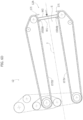
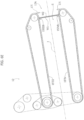
- the device 10 comprises a structure 12, which defines an inlet 12A for the blanks, a space S for receiving and accumulating the blanks, and an outlet 12B for extracting from the device the group of blanks formed thereby.
- the collecting space S extends along a reference axis J of the structure 12, and the inlet 12A and the outlet 12B are positioned on opposite sides of the space S, along the reference axis J.
- This space constitutes the position of the device 10, where the single blanks W coming from the labeling unit 104 are received, and where the group of blanks under formation is housed.
- the structure 12 is arranged with at least one support - see supports 151, 1511, 15III and 151V of the preferred embodiment represented - which is configured for keeping the blank or blanks received in the collecting space S, near the inlet 12A and according to an orientation whereby the lying plane of the blanks is transversal to the reference axis J.
- This at least one support - 151, 1511, 15III and 151V - is movable along the reference axis J for moving away the already-received blank or blanks from said inlet 12A, and enabling housing of a new blank w2 in said collecting space S.
- the new blank is maintained in the aforesaid orientation transverse to the axis J, by the same blank or same blanks already received in the space S.
- this at least one support - 151, 1511, 15III and 151V - is moved continuously and at a constant speed along the reference axis J.
- the device described here is able to control the formation of the group of blanks within the space S, ensuring, on the one hand, the correct positioning of the blanks at the inlet, and on the other hand, that the blanks keep in contact with each other and are mutually aligned.
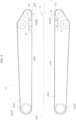
- the structure 12 comprises two frame planar modules 14, 16, which are oriented vertically and are arranged opposite each other, at a given distance, to define the collecting space S indicated above between them.
- the two frame modules 14, 16 extend parallel to each other, along the reference direction J.
- An assembly of belt-like supports 151, 1511, 15III and 151V is mounted on the two modules 14 and 16, each of which constitutes a movable support as discussed above.
- the two supports 151 and 1511 are mounted on the frame module 14, and the two supports 15111 and 151V on the frame module 16.
- belt-like supports are mounted on respective pulleys, so that each one extends along a closed-loop path having at least one section oriented along the reference axis J and of a length such as to connect the inlet 12A and the outlet 12B.
- the two portions 15'11 and 15'IV are aligned and spaced apart horizontally to engage opposite end regions of the lower edge of each blank W received in the space S.
- the portions 15'1, 15'111 are arranged correspondingly near the upper edge of each blank W received in the space S
- the belt-like supports 151, 1511, 15III and 151V have respective abutment portions 15IB, 1511B, 15IIIB, 15IVB, which protrude in a plane transverse to the longitudinal direction of the support, and are arranged to be positioned at the portions 15'1, 15'11, 15'111 and 15'IV to each engage the front face - with reference to the feed direction - of the blank which, in a given operating cycle, is first received within the space S.
- the abutment portions 15IB, 1511B, 15IIIB, 15IVB are all arranged at the inlet 12A, and aligned with each other in the same plane Q transverse to the reference axis J.
- the first blank W1 that is received in the space S places its lower edge on the two supports 1511 and 151V, and its front face against the abutment portions 151B, 1511B, 15IIIB and 15IVB ( Figure 6B ).
- the blank W1 is, therefore, oriented parallel to the plane Q identified by the abutment portions 151B, 1511B, 15IIIB and 15IVB.
- the supports 151, 1511, 15III and 151V are moved in such a way as to move away the respective abutment portions from the inlet 12A, and with them the previously received blank W1.
- the new blank W2 therefore, places its lower edge resting on the two belt-like supports 1511 and 151V and carries its front face against the previously received blank W1 ( Figures 6D and 6E ).
- the new blank W2 is also positioned substantially parallel to the plane Q.
- the movement of the supports 151, 1511, 15III and 151V is continuous and at a constant speed, and is regulated so as to keep the already-received blanks, grouped against each other and close to the inlet 12A.
- This movement is coordinated, in general, with the device located upstream of the device 10 which is suitable for delivering the various blanks.
- this movement is coordinated with the drum 102 and is carried out until a given group of blanks has formed within the space S (for example, this group could have the same number of blanks in the group that had been loaded on the feed unit 102 or not) ( Figure 6F ).
- the abutment portions 151B, 1511B, 15IIIB, 15IVB will find themselves at a distance from the inlet 12A corresponding, substantially, to the length of the reconstituted group of blanks.
- the supports 151, 1511, 15III and 151V are equipped with additional abutment portions - see the portions 15IIIC and 15IVC illustrated in Figure 3 - arranged to position themselves at the inlet 12A - in the same configuration shown in Figure 6A for the abutment portions 15IIIB and 15IVB - when the abutment portions 151B, 1511B, 15111B, 151VB are now out of the active sections 15'1, 15'11, 15'111 and 15'IV of the supports, to allow immediate start of a new loading cycle of blanks.
- the structure 12 can also be arranged with fixed guides 13, opposite to each other, carried by the two frame modules 14 and 16, to retain the blanks laterally.
- the movable supports 151, 1511, 15III and 151V must, in turn, be synchronized with each other.
- these supports are controlled by a single actuator 18, which is connected to the various supports 151, 1511, 15III and 151V through a motion transmission system, with belt members or equivalent members (e.g. chains).
- a single actuator 18 which is connected to the various supports 151, 1511, 15III and 151V through a motion transmission system, with belt members or equivalent members (e.g. chains).
- two or more actuators could be provided, for example, an actuator for each belt-like support.
- the motion transmission system comprises shafts 221, 2211, 22III and 22IV, rotatably mounted on the frame modules 14 and 16, which carry, on the inner side of the two modules, pulleys 231, 2311, 23III and 23IV, and on the outer side, pulleys 211, 2111, 21111 and 211V.
- the shaft 2211 has a connecting portion through which it connects to the actuator 18.
- An additional shaft 23 extends between the two frame modules 14, 16, and is rotatably mounted on both modules.
- the shaft 23 has opposite ends which are positioned on the two outer sides of the frame modules 14 and 16, and on which two additional pulleys 24 and 25 are carried.
- the belt-like supports 151, 1511, 15III and 151V are mounted, respectively, on the pulleys 231, 2311, 23III and 231V.
- a first belt member 26 is coupled, connecting them in rotation to each other, to the pulleys 211, 2111 and 24, which are all on the same outer side - the left side, with reference to the Figure - of the two frame modules 14 and 16.
- a second belt member 27 is coupled to the pulleys 21111, 211V and 25, which are, however, all on the opposite outer side of the two frame modules 14 and 16 - the right side, with reference to the Figure.
- each of the pulleys 231, 2311, 24 and 25 is associated with a pressure roller 29, which is configured to press the relative belt member against it, to ensure correct coupling between member and pulley.
- the actuator 18 is designed to control the rotation of the shaft 2211.
- This rotation controls the movement of the support 1511. On the other hand, it sets the first member 26 in motion, which, in turn, moves the support 151.
- the movement of the first member 26 is transmitted to the second member 27, on the opposite side of the structure 12, through the shaft 23.
- the second member 27 drives the other two supports 15111 and 151V.
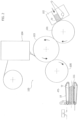
- the structure 12 is carried by a positioning unit 30, which is configured to move the structure 12 between a position P1, preferably raised, for loading the blanks (illustrated in Figure 1 ), and a position P2 , preferably lowered, of delivery of the blanks (illustrated in Figure 2 ).
- the structure 12 in the loading position P1, has the inlet 12A directly facing, and in immediate adjacency, to the drum 105.
- the structure 12 is oriented so as to arrange the reference axis J slightly inclined upwards, so as to facilitate the passage of the blanks from the drum 105 to the collecting space S.
- the structure 12 also comprises two holding elements 17, which are positioned at the entrance 12A and are opposite each other ( Figure 3 ).
- teeth are sized so that the passage defined by them is slightly smaller than the corresponding size of the blanks, so as to allow the insertion of the blanks, through a small deformation of the blanks along the respective upper and lower edges, and to be able instead to retain the already-received blanks, preventing the risk of spillage.
- the teeth 171 could define a passage slightly larger than the size of the blanks; in this case the release of the blank takes place by first inserting the blank behind the upper tooth and then behind the lower tooth.
- these teeth could be tilting and engage the inlet 12A of the structure only after the positioning of a blank in the collecting space S.
- the structure 12 is positioned at an underlying conveying line, on which the group of blanks is released.
- this conveying line comprises a carriage 111, which is inserted between the two frame modules 14 and 16 and the relative supports 1511 and 151V when the structure 12 lowers into the delivery position P2, engaging the group of blanks contained within the collecting space S with a support plane 111A.
- the delivery position P2 is selected so that the blanks resting on the support plane 111A are slightly raised with respect to the supports 1511 and 151V.
- the supports 151, 1511, 15III and 151V are moved so that the respective abutment portions 151B, 1511B, 15IIIB and 15IVB are removed from the respective sections 15'1, 15'11, 15'111 and 15'IV for engaging the blanks, thus freeing, frontally, the group of blanks.
- the carriage 111 can, at this point, extract the group of blanks through the outlet 12B.
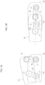
- FIGS. 5A and 5B illustrate the positioning unit 30, indicated above, according to a preferred embodiment of the device 10 described here.
- the unit 30 comprises two pivoting supports 32, 34, which are hinged around two fixed horizontal rotation axes, 11, 12, respectively.
- the two axes 11 and 12 are mutually parallel, and transverse to the reference axis J of the structure 12.
- These supports 32, 34 are, in turn, hinged to the two frame modules 14 and 16, around two movable rotation axes 13, 14, parallel to the axes I1 and 12, and mutually spaced apart along the reference axis J.
- the two pivoting supports 32 and 34 are both controlled by an actuator 35, which is connected thereto by means of a motion transmission system (not illustrated), for example, belt driven.
- the two supports 32 and 34 are movable between a lying position, in which they place the structure 12 in the aforesaid delivery position P2, and a vertical or slightly inclined position with respect to the vertical position, in which the structure 12 is held in the aforesaid loading position P1.
- the device 10 will also comprise a control unit U (schematically illustrated in Figure 1 ) for governing the operations of the described means.
- the above described positioning unit 30 causes a roto-translation of the structure 12 in order to move it between the loading position P1 and the delivery position P2.
- the device 10 could comprise a positioning unit 30 such as to determine only a translation of the structure 12 in order to move it between the loading position P1 and the delivery position P2.
- the structure 12 may not be movable between the two positions of loading and delivery; in this case, an element for extracting the pile of blanks from the collecting space S could fit into said collecting space S.
- An ordered group of unlabeled blanks W is loaded onto the feeding unit 102.
- the single blanks of this group are, in succession, taken from the drum 101, carried to the labeling unit 104 by the drum 103, and finally released to the device 10 by the drum 105.
- the structure 12 is in the loading position P1 illustrated in Figure 1 to accommodate the single blanks through the inlet 12A.
- the belt-like supports 151, 1511, 15III, 151V are operated according to a continuous movement and at a constant speed, to keep the already-received blanks grouped against each other and close to the inlet 12A.
- the structure 12 is carried to the delivery position P2 illustrated in Figure 2 , where the group of blanks is placed on the carriage 111.
- the belt-like supports 151, 1511, 15III, 151V are operated once again to free the group of blanks from the engagement of the abutment portions 15IB, 15IIB, 15IIIB, 15IVB.
- the carriage 111 extracts the group of blanks from the structure 12, through the outlet 12B, and transports them directly to the packaging machine mentioned above.
- the treatment process carried out by the machine 100 can be performed in line with the packaging process without the speed of the first machine affecting the speed of the second, and vice versa, thanks to the device 10, which operates to generate a reserve of blanks directly upstream of the packaging machine.
- the belt-like supports described can be replaced by rigid, movable support members of reciprocating motion along the reference axis J.
Landscapes
- Engineering & Computer Science (AREA)
- Mechanical Engineering (AREA)
- Making Paper Articles (AREA)
- Wrapping Of Specific Fragile Articles (AREA)
Description
- The present invention relates to a device for grouping blanks of smoking-article wrappers, coming one after another from a unit for treating said blanks, according to claim 1.
- It is known in the art to subject ordered groups of blanks, for example, bundles or stacks of blanks, to a treatment process in which the group of blanks is broken up, the individual blanks are fed to a treatment unit which performs a given operation on them (for example, a printing or labeling operation), and finally the single blanks are grouped again in an ordered group.
- The patent
IT 1340565 US2004/255800 A1 , by the same Applicant describes a treatment process of this type to generate, outside the packaging line for smoking articles, a reserve of treated blanks to be used for supplying the same packaging line. - This patent describes a device for grouping blanks in an ordered group, after they have undergone treatment. This known device comprises a rotatable drum provided with a plurality of radial hoppers which are movable, by rotating the drum, between a position for receiving the single blanks and a delivery position for the reconstituted group of blanks.
- Upstream of the aforesaid drum, the known device in question also comprises an inclined plane arranged to overturn the individual blanks directed towards one of the hoppers of the drum so that they are arranged parallel to the bottom of the hopper and are deposited one on top of the other to form a pile of blanks.
-
US 6,206,815 B1 ,US 2011/0315510 A1 ,GB 430,393 A CN 205471912 U andUS 5,727,674 A disclose each a device for grouping blanks. -
US 2013/0004285 A1 andUS 5,447,262 A disclose each a device for zig-zag folding of a web. -
US 5,233,814 A discloses a device being movable between a position of loading letters and a position of delivery of a group of letters. - The present invention has the object of providing an improved grouping device with respect to the known device indicated, in particular from the point of view of the operating mode and the speed of forming the pile of blanks.
- This object is achieved by a device having the characteristics referred to in claim 1. The solution described herein also relates to a method according to claim 11 and a machine according to
claim 13. - The claims form an integral part of the technical disclosure provided here in relation to the invention.
- Further characteristics and advantages of the invention will become evident from the description that follows with reference to the attached drawings, provided purely by way of non-limiting example, wherein:
-
Figure 1 represents a treatment machine for blanks wherein a grouping device according to an embodiment of the solution described here is used; -
Figure 2 represents the machine ofFigure 1 wherein the grouping device is in a different operating step; -
Figure 3 represents a side view of the grouping device ofFigure 1 ; -
Figure 4 represents a front view of the grouping device illustrated inFigure 1 ; -
Figures 5A and 5B represent, in a simplified manner, the grouping device ofFigure 1 in two different operating conditions, respectively; -
Figures 6A to 6F represent successive steps of the operation of the grouping device ofFigure 1 ; -
Figure 7 illustrates an example of a blank for wrapping smoking articles. - In the following description, various specific details are illustrated aimed at a thorough understanding of the embodiments. In other cases, known structures, materials or operations are not shown or described in detail to avoid obscuring various aspects of the embodiments.
- The references used here are only for convenience and do not therefore define the field of protection or the scope of the embodiments.
- As mentioned above, the device described herein performs the function of grouping blanks of smoking-article wrappers which come out in succession from a unit for treating these blanks.
- To better illustrate the type of application for which the device described here is intended,
Figure 1 illustrates an example of a treatment machine for blanks W, which, in particular, carries out a labeling process. - The illustrated machine, indicated as a whole by reference 100, comprises a
unit 102 for feeding the blanks W, alabeling unit 104 and adevice 10 made according to the disclosures provided here. - The machine 100 also includes
drums feeding unit 102 to thelabeling unit 104, and from this to thegrouping device 10. - The
feeding unit 102 is designed to receive an ordered group of blanks and feed them in succession to thedrum 101. - Each blank W is constituted by a sheet, usually made of paper or cardboard, which is in a completely extended condition, so as to present a planar conformation.
- The blanks that are received by the
unit 102 are arranged in an orderly manner so as to form a bundle or pile of blanks. In other words, they are in mutual contact at their respective opposite faces, and have the same orientation with respect to an axis perpendicular to their lying plane. -
Figure 7 illustrates, by way of example, a blank W of a cigarette packet, which must be subjected to the labeling process carried out by the machine 100 ofFigure 1 . - This blank has a given contour and predefined folding lines, so that it can be formed into the final wrapper simply by folding its various portions and their mutual connection (usually by means of glue). This figure illustrates an adhesive label T, which is applied on the blank by the
labeling unit 104, to constitute a sealing label for the packet of cigarettes. - The
drum 101 is arranged to pick up one blank at a time from thefeeding unit 102 and transfer it to thedrum 103. In turn, thedrum 103 receives the blank from thedrum 101 and carries it, first, to theunit 104 for applying the label T and, subsequently, to thedrum 105. Finally, thedrum 105 picks up the blank from thedrum 103 and delivers it to thedevice 10. - To carry out the dual function indicated, for picking up and transferring the blanks, the two
drums - The sequence of steps described above is carried out on all blanks that have been loaded on the
unit 102. - The
device 10 operates to group the blanks provided with a label coming from thelabeling unit 104, reconstituting an ordered group of blanks. - As will be seen below, this group of blanks can be directly used for supplying a packaging machine (not illustrated) arranged in line with the machine 100.
- With reference now to
Figures 3 and4 , in various preferred embodiments, as well as in the one illustrated, thedevice 10 comprises astructure 12, which defines aninlet 12A for the blanks, a space S for receiving and accumulating the blanks, and anoutlet 12B for extracting from the device the group of blanks formed thereby. - The collecting space S extends along a reference axis J of the
structure 12, and theinlet 12A and theoutlet 12B are positioned on opposite sides of the space S, along the reference axis J. - This space constitutes the position of the
device 10, where the single blanks W coming from thelabeling unit 104 are received, and where the group of blanks under formation is housed. - According to an important characteristic of the device described here, the
structure 12 is arranged with at least one support - seesupports inlet 12A and according to an orientation whereby the lying plane of the blanks is transversal to the reference axis J. - This at least one support - 151, 1511, 15III and 151V - is movable along the reference axis J for moving away the already-received blank or blanks from said
inlet 12A, and enabling housing of a new blank w2 in said collecting space S. - The new blank is maintained in the aforesaid orientation transverse to the axis J, by the same blank or same blanks already received in the space S.
- Preferably, this at least one support - 151, 1511, 15III and 151V - is moved continuously and at a constant speed along the reference axis J.
- Thanks to the indicated characteristics, the device described here is able to control the formation of the group of blanks within the space S, ensuring, on the one hand, the correct positioning of the blanks at the inlet, and on the other hand, that the blanks keep in contact with each other and are mutually aligned.
- In various preferred embodiments, as well as in the one illustrated, the
structure 12 comprises two frameplanar modules - The two
frame modules - An assembly of belt-
like supports modules frame module 14, and the two supports 15111 and 151V on theframe module 16. - These belt-like supports are mounted on respective pulleys, so that each one extends along a closed-loop path having at least one section oriented along the reference axis J and of a length such as to connect the
inlet 12A and theoutlet 12B. - The respective portions 15'1, 15'11, 15'111 and 15'IV of these supports which extend along this section cooperate together to support the blanks W received in the space S in the aforesaid orientation transverse to the axis J (
Figure 4 ). - The two portions 15'11 and 15'IV are aligned and spaced apart horizontally to engage opposite end regions of the lower edge of each blank W received in the space S.
- On the other hand, the portions 15'1, 15'111 are arranged correspondingly near the upper edge of each blank W received in the space S
- The belt-
like supports - With reference to
Figure 6A , when a new cycle is started, the abutment portions 15IB, 1511B, 15IIIB, 15IVB are all arranged at theinlet 12A, and aligned with each other in the same plane Q transverse to the reference axis J. - The first blank W1 that is received in the space S places its lower edge on the two supports 1511 and 151V, and its front face against the abutment portions 151B, 1511B, 15IIIB and 15IVB (
Figure 6B ). - The blank W1 is, therefore, oriented parallel to the plane Q identified by the abutment portions 151B, 1511B, 15IIIB and 15IVB.
- To receive a new blank W2, the
supports inlet 12A, and with them the previously received blank W1. - The extent of this movement is such as to make room for the new blank W2 (
Figure 6C ), and, at the same time, keep the blank W1 close enough to theinlet 12A so that the new blank W2 is carried directly against the blank W1, as soon as it passes the 12A inlet. - The new blank W2, therefore, places its lower edge resting on the two belt-
like supports 1511 and 151V and carries its front face against the previously received blank W1 (Figures 6D and6E ). - Thanks to the positioning of the blank W1, the new blank W2 is also positioned substantially parallel to the plane Q.
- This sequence is repeated for all blanks that are received in the space S.
- Preferably, the movement of the
supports inlet 12A. - This movement is coordinated, in general, with the device located upstream of the
device 10 which is suitable for delivering the various blanks. - With reference to the application example illustrated in
Figures 1 and2 , this movement is coordinated with thedrum 102 and is carried out until a given group of blanks has formed within the space S (for example, this group could have the same number of blanks in the group that had been loaded on thefeed unit 102 or not) (Figure 6F ). - Incidentally, it will be understood that at the end of the operating cycle, the abutment portions 151B, 1511B, 15IIIB, 15IVB will find themselves at a distance from the
inlet 12A corresponding, substantially, to the length of the reconstituted group of blanks. - Preferably, the
supports Figure 3 - arranged to position themselves at theinlet 12A - in the same configuration shown inFigure 6A for the abutment portions 15IIIB and 15IVB - when the abutment portions 151B, 1511B, 15111B, 151VB are now out of the active sections 15'1, 15'11, 15'111 and 15'IV of the supports, to allow immediate start of a new loading cycle of blanks. - Referring to
Figure 4 , thestructure 12 can also be arranged with fixedguides 13, opposite to each other, carried by the twoframe modules - The
movable supports - In various preferred embodiments, as well as in the one illustrated, these supports are controlled by a
single actuator 18, which is connected to thevarious supports - With reference to the preferred embodiment illustrated in
Figure 4 , the motion transmission system comprisesshafts frame modules shaft 2211 has a connecting portion through which it connects to theactuator 18. - An
additional shaft 23 extends between the twoframe modules shaft 23 has opposite ends which are positioned on the two outer sides of theframe modules additional pulleys - The belt-
like supports pulleys - A
first belt member 26 is coupled, connecting them in rotation to each other, to thepulleys frame modules - In the same way, a
second belt member 27 is coupled to thepulleys 21111, 211V and 25, which are, however, all on the opposite outer side of the twoframe modules 14 and 16 - the right side, with reference to the Figure. - In various preferred embodiments, as well as in the one illustrated, each of the
pulleys pressure roller 29, which is configured to press the relative belt member against it, to ensure correct coupling between member and pulley. - It will be noted that the two
members shaft 23. - The
actuator 18 is designed to control the rotation of theshaft 2211. - This rotation, on the one hand, controls the movement of the
support 1511. On the other hand, it sets thefirst member 26 in motion, which, in turn, moves thesupport 151. - The movement of the
first member 26 is transmitted to thesecond member 27, on the opposite side of thestructure 12, through theshaft 23. - The
second member 27 drives the other two supports 15111 and 151V. - The above described motion transfer system is only one of the possible embodiments.
- Returning to
Figures 1 and2 , thestructure 12 is carried by apositioning unit 30, which is configured to move thestructure 12 between a position P1, preferably raised, for loading the blanks (illustrated inFigure 1 ), and a position P2 , preferably lowered, of delivery of the blanks (illustrated inFigure 2 ). - With reference to
Figure 1 , in the loading position P1, thestructure 12 has theinlet 12A directly facing, and in immediate adjacency, to thedrum 105. - At the same time, the
structure 12 is oriented so as to arrange the reference axis J slightly inclined upwards, so as to facilitate the passage of the blanks from thedrum 105 to the collecting space S. - In various preferred embodiments, as well as in the one illustrated, the
structure 12 also comprises two holdingelements 17, which are positioned at theentrance 12A and are opposite each other (Figure 3 ). - These elements are equipped with
respective teeth 171 between which the inlet passage of the blanks W into the collecting space S is defined. - These teeth are sized so that the passage defined by them is slightly smaller than the corresponding size of the blanks, so as to allow the insertion of the blanks, through a small deformation of the blanks along the respective upper and lower edges, and to be able instead to retain the already-received blanks, preventing the risk of spillage.
- Alternatively, the
teeth 171 could define a passage slightly larger than the size of the blanks; in this case the release of the blank takes place by first inserting the blank behind the upper tooth and then behind the lower tooth. - As a further alternative, these teeth could be tilting and engage the
inlet 12A of the structure only after the positioning of a blank in the collecting space S. - With reference to
Figure 2 , in the delivery position P2, thestructure 12 is positioned at an underlying conveying line, on which the group of blanks is released. - In the illustrated example, this conveying line comprises a
carriage 111, which is inserted between the twoframe modules structure 12 lowers into the delivery position P2, engaging the group of blanks contained within the collecting space S with asupport plane 111A. - Preferably, the delivery position P2 is selected so that the blanks resting on the
support plane 111A are slightly raised with respect to thesupports 1511 and 151V. - After the group of blanks has been placed on the
carriage 111, thesupports - The
carriage 111 can, at this point, extract the group of blanks through theoutlet 12B. - With reference now to
Figures 5A and 5B , these illustrate thepositioning unit 30, indicated above, according to a preferred embodiment of thedevice 10 described here. - According to this embodiment, the
unit 30 comprises two pivoting supports 32, 34, which are hinged around two fixed horizontal rotation axes, 11, 12, respectively. The twoaxes 11 and 12 are mutually parallel, and transverse to the reference axis J of thestructure 12. - The distal ends of these
supports frame modules - The two pivoting supports 32 and 34 are both controlled by an
actuator 35, which is connected thereto by means of a motion transmission system (not illustrated), for example, belt driven. - With reference to
Figures 5A and 5B , the twosupports structure 12 in the aforesaid delivery position P2, and a vertical or slightly inclined position with respect to the vertical position, in which thestructure 12 is held in the aforesaid loading position P1. - Clearly, the
device 10 will also comprise a control unit U (schematically illustrated inFigure 1 ) for governing the operations of the described means. - The above described positioning unit 30 (corresponding to the illustrated embodiment) causes a roto-translation of the
structure 12 in order to move it between the loading position P1 and the delivery position P2. Alternatively, thedevice 10 could comprise apositioning unit 30 such as to determine only a translation of thestructure 12 in order to move it between the loading position P1 and the delivery position P2. - As another alternative, the
structure 12 may not be movable between the two positions of loading and delivery; in this case, an element for extracting the pile of blanks from the collecting space S could fit into said collecting space S. - Returning to the application example illustrated in
Figures 1 and2 , a complete cycle of operation of the illustrated machine 100 develops as follows. - An ordered group of unlabeled blanks W is loaded onto the
feeding unit 102. - The single blanks of this group are, in succession, taken from the
drum 101, carried to thelabeling unit 104 by thedrum 103, and finally released to thedevice 10 by thedrum 105. - During this step, the
structure 12 is in the loading position P1 illustrated inFigure 1 to accommodate the single blanks through theinlet 12A. - The belt-
like supports inlet 12A. - Once the collecting space S is filled with labeled blanks W, the
structure 12 is carried to the delivery position P2 illustrated inFigure 2 , where the group of blanks is placed on thecarriage 111. - The belt-
like supports - At this point, the
carriage 111 extracts the group of blanks from thestructure 12, through theoutlet 12B, and transports them directly to the packaging machine mentioned above. - It will be noted that the treatment process carried out by the machine 100 can be performed in line with the packaging process without the speed of the first machine affecting the speed of the second, and vice versa, thanks to the
device 10, which operates to generate a reserve of blanks directly upstream of the packaging machine. - Of course, the details of construction and the embodiments may vary, even significantly, with respect to those illustrated here, purely by way of non-limiting example, without departing from the scope of the invention as defined by the attached claims. For example, alternative embodiments to that illustrated may provide only the lower belt-
like supports 1511 and 151V or the two lower belt-like supports 1511 and 151V and a single upper belt-like support. - Outside the subject-matter of the claims, the belt-like supports described can be replaced by rigid, movable support members of reciprocating motion along the reference axis J.
Claims (14)
- A device (10) for grouping blanks (w1, w2) of smoking-article wrappers, coming one after another from a machine (104) for treating said blanks,said device (10) comprising a structure (12) for receiving said blanks (w1, w2) having an inlet (12A) for said blanks coming from said treatment machine (104), and a collecting space (S), in communication with said inlet (12A), for receiving said blanks and housing a group of said blanks (w1, w2) under formation,wherein said collecting space (S) extends along a reference axis (J) of said structure (12),said device also comprising at least one support (151, 1511, 15III, 15IV), which is movably mounted on said structure (12), for keeping the already-received blank or blanks in said collecting space close to said inlet (12A) and according to such an orientation that the lying plane of said blanks is transversal to said reference axis (J),wherein said at least one support (151, 1511, 15III, 151V) is movable along said reference axis (J) for moving away the already-received blank or blanks (w1) from said inlet (12A), and enabling reception of a new blank (w2) in said collecting space (S),wherein said at least one movable support (1511, 151V) comprises at least one belt-like support (1511, 15IV), which is movable along a ring-like closed path having a portion oriented along said reference axis (J), and wherein the portion (15'11, 15'IV) of said at least one belt-like support (1511, 151V) extending along said portion is configured to engage a lower side of the group of said blanks under formation, received within said collecting space (S),said device being characterized in that said belt-like support (1511, 151V) comprises one or more abutment portions (15IIB, 15IVB) configured to engage the front side of the blank that, in a given cycle of operation of said device, is first received in said collecting chamber (S), and for keeping said blank or the blanks that are received afterwards, in said orientation transversal to said reference axis (J).
- A device according to claim 1, wherein said at least one support (151, 1511, 15III, 151V) is movable according to a continuous movement, preferably, at constant velocity.
- A device according to claims 1 or 2, comprising an actuator (18) for driving said at least one movable support (151, 1511, 15III, 151V) and a control unit (U) configured to control said actuator (18) so that the movement of said at least one movable support (151, 1511, 15III, 151V) frees the space that is necessary to receive the new blank, and - at the same time - keeps the already-received blank or the blank sufficiently close to said inlet (12A) so that they can support said new blank in said orientation transversal to said reference axis (J).
- A device according to any one of the preceding claims, comprising an actuator (18) for driving said at least one belt-like support (1511, 151V) and a control unit (U) configured to control said actuator (18),
wherein, in an operation cycle of said device, said control unit (U) is configured to control the movement of said at least one belt-like support (1511, 151V) for carrying said one or more abutment portions (15IIB, 15IVB) from a first position close to said inlet (12A), to a second position where said one or more abutment portions (1511b, 15IVB) find themselves at a distance from said inlet (12A) that is substantially equal to the dimension, along said reference axis (J), of said group of blanks formed in said collecting space (S). - A device according to any one of the preceding claims, wherein said at least one belt-like support (1511, 151V) comprises a first and a second belt-like support (1511, 151V), which are configured to engage the lower side of said group of blanks under formation received in said collecting space (S), and are spaced apart from one another, along a direction orthogonal to said reference axis (J), by a predetermined distance for allowing insertion between said first and second belt-like support (1511, 151V) of a device (111) for picking up the group of blanks formed in said collecting space (S).
- A device according to any one of the preceding claims, wherein said at least one movable support (151, 15111) comprises at least one additional belt-like support (151, 15111), which is positioned on the upper side of said group of blanks under formation, and is mounted to be movable along a closed-loop path having a portion oriented along said reference axis (J), wherein said additional belt-like support (151, 15111) comprises one or more abutment portions (15IB, 15IIIB) configured to engage the front side of the blank (w1) which, in a given operation cycle of said device (10), is first received in said collecting space (S), and for keeping said blank (w1) and the blanks (w2, W) that are received afterwards, in said orientation transversal to said reference axis (J).
- A device according to claims 3, 5 and 6, comprising a motion-transmission system (26, 27, 23) configured to operatively connect said actuator (18) to said first and second belt-like supports (1511, 151V) and to said additional belt-like support (151, 15111).
- A device according to any one of the preceding claims, wherein said structure (12) has an outlet (12B), for said group of blanks formed in said collecting space (S), which communicates with said collecting space (S) and is positioned at the side opposite to said inlet, along said reference axis (J).
- A device (10) according to any one of the preceding claims, wherein said structure (12) is movable between a position (P1) for loading said blanks (w1, w2, W) wherein said blanks are received in said collecting space (S) of said structure (12), and a delivery position (P2) wherein the group of blanks (w1, w2, W) formed inside said collecting space (S) is released.
- A device according to any one of the preceding claims, wherein said structure (12) is provided, at said inlet (12A), with a pair of holding elements (17) that are opposite to one another for holding the blanks already received in said collecting space (S).
- A method for grouping blanks (w1, w2) of smoking-article wrappers coming - in succession - from a machine (104) for treating said blanks, said method being implemented by means of a device (10) for grouping blanks (w1, w2) of smoking-article wrappers according to any one of the preceding claims, and comprising the step of feeding in succession, one after another, said blanks to said device (10) for grouping blanks,
said method, furthermore, comprising the steps of:- receiving, through said inlet (12A), a blank (w1) within said collecting space (S), said at least one support (151, 1511, 15III, 151V) keeping said blank (w1) close to said inlet (12A) and according to said orientation transversal to said reference axis (J);- moving said at least one support (151, 1511, 15III, 151V) along said reference axis (J) for moving said blank (w1) received in said collecting space (S) away from said inlet (12A);- receiving, through said inlet (12A), a new blank (w2) in said collecting space (S), said new blank (w2) positioning itself against the previously received blank (w1), according to said orientation transversal to said reference axis (J);- repeating the previous steps until an ordered group of blanks is formed in said collecting space (S). - A method according to claim 11, wherein said movement of said at least one support (151, 1511, 15III, 151V) is a continuous movement, preferably at constant velocity, which is executed without interruptions while the single blanks (w1, w2) are received in said collecting space (S) for forming said given ordered group of blanks (w1, w2, W).
- A machine (100) for treating blanks of smoking-articles wrappers, comprising:- a unit (104) for treating blanks (w1, w2) of smoking-articles wrappers;- at least one drum (101, 103) for feeding, in succession, one blank at a time, to said treating unit (104),- a device (10) according to any one of claims 1 to 10, which is positioned downstream of said treating unit (104), for grouping - in an ordered group - the blanks (w1, w2, W) that have been treated by said treating unit (104);- a carriage (111) for picking up the ordered group of treated blanks from said device (10) and transporting said group of treated blanks towards a packaging machine.
- A machine (100) according to claim 13, wherein said structure (12) of said device (10) is movable between a position (P1) of loading of said blanks and a position (P2) of delivery of said group of blanks formed in said collecting space (S), and wherein said carriage (111) is configured to pick up said group of blanks when the structure (12) of said device (10) is in said delivery position (P2).
Applications Claiming Priority (2)
| Application Number | Priority Date | Filing Date | Title |
|---|---|---|---|
| IT102019000007599A IT201900007599A1 (en) | 2019-05-30 | 2019-05-30 | Device for grouping blanks of wrapping articles for smoking |
| PCT/IB2020/054768 WO2020240349A1 (en) | 2019-05-30 | 2020-05-20 | A device for grouping blanks of wrappers of smoking articles |
Publications (2)
| Publication Number | Publication Date |
|---|---|
| EP3976516A1 EP3976516A1 (en) | 2022-04-06 |
| EP3976516B1 true EP3976516B1 (en) | 2024-11-13 |
Family
ID=67998642
Family Applications (1)
| Application Number | Title | Priority Date | Filing Date |
|---|---|---|---|
| EP20728562.8A Active EP3976516B1 (en) | 2019-05-30 | 2020-05-20 | A device and corresponding method for grouping blanks of wrappers of smoking articles |
Country Status (4)
| Country | Link |
|---|---|
| EP (1) | EP3976516B1 (en) |
| IT (1) | IT201900007599A1 (en) |
| PL (1) | PL3976516T3 (en) |
| WO (1) | WO2020240349A1 (en) |
Family Cites Families (9)
| Publication number | Priority date | Publication date | Assignee | Title |
|---|---|---|---|---|
| GB430393A (en) * | 1933-11-23 | 1935-06-18 | Chambon Ltd | Improvements in appliances for receiving sheets of board or similar articles |
| FR2676377B1 (en) * | 1991-05-14 | 1993-07-23 | Cie Gle Automatisme Cga Hbs | DEVICE FOR FILLING CONTAINERS, ESPECIALLY AT THE OUTPUT OF A MAIL SORTING MACHINE. |
| DE4234663A1 (en) * | 1992-10-15 | 1994-04-21 | Focke & Co | Device for transporting packaging material in web form |
| US5540422A (en) * | 1994-10-24 | 1996-07-30 | Baldwin Technology Corporation | Stacker-bundler transfer apparatus |
| DE19726324A1 (en) * | 1997-06-20 | 1998-12-24 | Focke & Co | Method and device for manufacturing hinged boxes |
| ITBO20030077A1 (en) * | 2003-02-20 | 2004-08-21 | Gd Spa | METHOD AND UNIT FOR HANDLING AND TREATMENT |
| US8333370B2 (en) * | 2010-04-14 | 2012-12-18 | C.G. Bretting Manufacturing Co., Inc. | Separator belt finger count apparatus and method |
| DE102010025223A1 (en) * | 2010-06-23 | 2011-12-29 | Palamides Gmbh | Transport device for flat products |
| CN205471912U (en) * | 2016-03-11 | 2016-08-17 | 江苏联通纪元印务股份有限公司 | Cigarette package printing auxiliary stay frame |
-
2019
- 2019-05-30 IT IT102019000007599A patent/IT201900007599A1/en unknown
-
2020
- 2020-05-20 EP EP20728562.8A patent/EP3976516B1/en active Active
- 2020-05-20 WO PCT/IB2020/054768 patent/WO2020240349A1/en not_active Ceased
- 2020-05-20 PL PL20728562.8T patent/PL3976516T3/en unknown
Also Published As
| Publication number | Publication date |
|---|---|
| EP3976516A1 (en) | 2022-04-06 |
| WO2020240349A1 (en) | 2020-12-03 |
| IT201900007599A1 (en) | 2020-11-30 |
| PL3976516T3 (en) | 2025-01-27 |
Similar Documents
| Publication | Publication Date | Title |
|---|---|---|
| US5996310A (en) | Packaging apparatus | |
| US7234696B2 (en) | Method of, and apparatus for, handling blanks, in particular coupons | |
| CN104781146A (en) | High-efficiency packaging method for packaging, especially small-sized products, and high-efficiency packaging plant for, inter alia, carrying out the method | |
| CN109850249A (en) | Equipment for transportation and packing | |
| US6964147B2 (en) | Operating method for a packaging machine of the “sleeve” type, packaging machine for implementing the said method, and package produced by the said method | |
| CN105083613B (en) | Method and packaging machine for confectionery products | |
| CN113428406A (en) | Automatic cigarette packet machine | |
| JP7492579B2 (en) | Packaging machine for producing filter bags containing infusion products | |
| CN108298133B (en) | Method for transferring blister packs | |
| EP0900731B1 (en) | Packing machine | |
| GB2220187A (en) | Apparatus for transferring and applying wrappers to articles | |
| EP3976516B1 (en) | A device and corresponding method for grouping blanks of wrappers of smoking articles | |
| EP1346916B1 (en) | A method and a unit for feeding elements of sheet material to a product wrapping line | |
| EP2036819B1 (en) | Method and unit for feeding products to a group-forming unit | |
| EP0792807B1 (en) | Method and unit for folding packing blanks along preformed bend lines | |
| WO1999014141A1 (en) | Article transport system | |
| CN101391702B (en) | Method and device for supplying products to group forming device | |
| EP3328740B1 (en) | Machine for wrapping confectionery products | |
| US6705607B2 (en) | Device for transporting printed products | |
| EP0994027B1 (en) | Method and machine for packing a group of products | |
| KR100575236B1 (en) | Seasoned seaweed splitting device | |
| WO2001015975A2 (en) | System and method for wrapping articles | |
| EP0900730B1 (en) | Method and unit for supplying flat articles | |
| RU116836U1 (en) | PACKING MACHINE FOR A TECHNOLOGICAL LINE FOR PACKING BLOCKS OF CONTAINERS WITH FOOD PRODUCT AS A SET WITH A GIFT | |
| EP2407385B1 (en) | Unit and method for supplying sheets of material for wrapping cigarette packets and machine for packing said packets |
Legal Events
| Date | Code | Title | Description |
|---|---|---|---|
| STAA | Information on the status of an ep patent application or granted ep patent |
Free format text: STATUS: UNKNOWN |
|
| STAA | Information on the status of an ep patent application or granted ep patent |
Free format text: STATUS: THE INTERNATIONAL PUBLICATION HAS BEEN MADE |
|
| PUAI | Public reference made under article 153(3) epc to a published international application that has entered the european phase |
Free format text: ORIGINAL CODE: 0009012 |
|
| STAA | Information on the status of an ep patent application or granted ep patent |
Free format text: STATUS: REQUEST FOR EXAMINATION WAS MADE |
|
| 17P | Request for examination filed |
Effective date: 20211012 |
|
| AK | Designated contracting states |
Kind code of ref document: A1 Designated state(s): AL AT BE BG CH CY CZ DE DK EE ES FI FR GB GR HR HU IE IS IT LI LT LU LV MC MK MT NL NO PL PT RO RS SE SI SK SM TR |
|
| DAV | Request for validation of the european patent (deleted) | ||
| DAX | Request for extension of the european patent (deleted) | ||
| P01 | Opt-out of the competence of the unified patent court (upc) registered |
Effective date: 20230524 |
|
| GRAP | Despatch of communication of intention to grant a patent |
Free format text: ORIGINAL CODE: EPIDOSNIGR1 |
|
| STAA | Information on the status of an ep patent application or granted ep patent |
Free format text: STATUS: GRANT OF PATENT IS INTENDED |
|
| RIC1 | Information provided on ipc code assigned before grant |
Ipc: B65B 43/18 20060101ALI20240528BHEP Ipc: B65B 43/14 20060101ALI20240528BHEP Ipc: B65B 43/12 20060101ALI20240528BHEP Ipc: B65B 19/22 20060101ALI20240528BHEP Ipc: B65H 33/16 20060101ALI20240528BHEP Ipc: B65H 31/30 20060101ALI20240528BHEP Ipc: B65H 31/06 20060101AFI20240528BHEP |
|
| INTG | Intention to grant announced |
Effective date: 20240621 |
|
| GRAS | Grant fee paid |
Free format text: ORIGINAL CODE: EPIDOSNIGR3 |
|
| GRAA | (expected) grant |
Free format text: ORIGINAL CODE: 0009210 |
|
| STAA | Information on the status of an ep patent application or granted ep patent |
Free format text: STATUS: THE PATENT HAS BEEN GRANTED |
|
| AK | Designated contracting states |
Kind code of ref document: B1 Designated state(s): AL AT BE BG CH CY CZ DE DK EE ES FI FR GB GR HR HU IE IS IT LI LT LU LV MC MK MT NL NO PL PT RO RS SE SI SK SM TR |
|
| REG | Reference to a national code |
Ref country code: GB Ref legal event code: FG4D |
|
| REG | Reference to a national code |
Ref country code: CH Ref legal event code: EP |
|
| REG | Reference to a national code |
Ref country code: DE Ref legal event code: R096 Ref document number: 602020041279 Country of ref document: DE |
|
| REG | Reference to a national code |
Ref country code: IE Ref legal event code: FG4D |
|
| REG | Reference to a national code |
Ref country code: NL Ref legal event code: FP |
|
| REG | Reference to a national code |
Ref country code: LT Ref legal event code: MG9D |
|
| PG25 | Lapsed in a contracting state [announced via postgrant information from national office to epo] |
Ref country code: PT Free format text: LAPSE BECAUSE OF FAILURE TO SUBMIT A TRANSLATION OF THE DESCRIPTION OR TO PAY THE FEE WITHIN THE PRESCRIBED TIME-LIMIT Effective date: 20250313 Ref country code: HR Free format text: LAPSE BECAUSE OF FAILURE TO SUBMIT A TRANSLATION OF THE DESCRIPTION OR TO PAY THE FEE WITHIN THE PRESCRIBED TIME-LIMIT Effective date: 20241113 Ref country code: IS Free format text: LAPSE BECAUSE OF FAILURE TO SUBMIT A TRANSLATION OF THE DESCRIPTION OR TO PAY THE FEE WITHIN THE PRESCRIBED TIME-LIMIT Effective date: 20250313 |
|
| PG25 | Lapsed in a contracting state [announced via postgrant information from national office to epo] |
Ref country code: FI Free format text: LAPSE BECAUSE OF FAILURE TO SUBMIT A TRANSLATION OF THE DESCRIPTION OR TO PAY THE FEE WITHIN THE PRESCRIBED TIME-LIMIT Effective date: 20241113 |
|
| REG | Reference to a national code |
Ref country code: AT Ref legal event code: MK05 Ref document number: 1741559 Country of ref document: AT Kind code of ref document: T Effective date: 20241113 |
|
| PG25 | Lapsed in a contracting state [announced via postgrant information from national office to epo] |
Ref country code: BG Free format text: LAPSE BECAUSE OF FAILURE TO SUBMIT A TRANSLATION OF THE DESCRIPTION OR TO PAY THE FEE WITHIN THE PRESCRIBED TIME-LIMIT Effective date: 20241113 |
|
| PG25 | Lapsed in a contracting state [announced via postgrant information from national office to epo] |
Ref country code: ES Free format text: LAPSE BECAUSE OF FAILURE TO SUBMIT A TRANSLATION OF THE DESCRIPTION OR TO PAY THE FEE WITHIN THE PRESCRIBED TIME-LIMIT Effective date: 20241113 |
|
| PG25 | Lapsed in a contracting state [announced via postgrant information from national office to epo] |
Ref country code: NO Free format text: LAPSE BECAUSE OF FAILURE TO SUBMIT A TRANSLATION OF THE DESCRIPTION OR TO PAY THE FEE WITHIN THE PRESCRIBED TIME-LIMIT Effective date: 20250213 |
|
| PG25 | Lapsed in a contracting state [announced via postgrant information from national office to epo] |
Ref country code: AT Free format text: LAPSE BECAUSE OF FAILURE TO SUBMIT A TRANSLATION OF THE DESCRIPTION OR TO PAY THE FEE WITHIN THE PRESCRIBED TIME-LIMIT Effective date: 20241113 Ref country code: LV Free format text: LAPSE BECAUSE OF FAILURE TO SUBMIT A TRANSLATION OF THE DESCRIPTION OR TO PAY THE FEE WITHIN THE PRESCRIBED TIME-LIMIT Effective date: 20241113 Ref country code: GR Free format text: LAPSE BECAUSE OF FAILURE TO SUBMIT A TRANSLATION OF THE DESCRIPTION OR TO PAY THE FEE WITHIN THE PRESCRIBED TIME-LIMIT Effective date: 20250214 |
|
| PG25 | Lapsed in a contracting state [announced via postgrant information from national office to epo] |
Ref country code: RS Free format text: LAPSE BECAUSE OF FAILURE TO SUBMIT A TRANSLATION OF THE DESCRIPTION OR TO PAY THE FEE WITHIN THE PRESCRIBED TIME-LIMIT Effective date: 20250213 |
|
| PGFP | Annual fee paid to national office [announced via postgrant information from national office to epo] |
Ref country code: NL Payment date: 20250526 Year of fee payment: 6 |
|
| PG25 | Lapsed in a contracting state [announced via postgrant information from national office to epo] |
Ref country code: SM Free format text: LAPSE BECAUSE OF FAILURE TO SUBMIT A TRANSLATION OF THE DESCRIPTION OR TO PAY THE FEE WITHIN THE PRESCRIBED TIME-LIMIT Effective date: 20241113 |
|
| PGFP | Annual fee paid to national office [announced via postgrant information from national office to epo] |
Ref country code: PL Payment date: 20250506 Year of fee payment: 6 Ref country code: DE Payment date: 20250529 Year of fee payment: 6 |
|
| PG25 | Lapsed in a contracting state [announced via postgrant information from national office to epo] |
Ref country code: DK Free format text: LAPSE BECAUSE OF FAILURE TO SUBMIT A TRANSLATION OF THE DESCRIPTION OR TO PAY THE FEE WITHIN THE PRESCRIBED TIME-LIMIT Effective date: 20241113 |
|
| PG25 | Lapsed in a contracting state [announced via postgrant information from national office to epo] |
Ref country code: EE Free format text: LAPSE BECAUSE OF FAILURE TO SUBMIT A TRANSLATION OF THE DESCRIPTION OR TO PAY THE FEE WITHIN THE PRESCRIBED TIME-LIMIT Effective date: 20241113 |
|
| PG25 | Lapsed in a contracting state [announced via postgrant information from national office to epo] |
Ref country code: RO Free format text: LAPSE BECAUSE OF FAILURE TO SUBMIT A TRANSLATION OF THE DESCRIPTION OR TO PAY THE FEE WITHIN THE PRESCRIBED TIME-LIMIT Effective date: 20241113 |
|
| PG25 | Lapsed in a contracting state [announced via postgrant information from national office to epo] |
Ref country code: SK Free format text: LAPSE BECAUSE OF FAILURE TO SUBMIT A TRANSLATION OF THE DESCRIPTION OR TO PAY THE FEE WITHIN THE PRESCRIBED TIME-LIMIT Effective date: 20241113 |
|
| PG25 | Lapsed in a contracting state [announced via postgrant information from national office to epo] |
Ref country code: CZ Free format text: LAPSE BECAUSE OF FAILURE TO SUBMIT A TRANSLATION OF THE DESCRIPTION OR TO PAY THE FEE WITHIN THE PRESCRIBED TIME-LIMIT Effective date: 20241113 |
|
| PG25 | Lapsed in a contracting state [announced via postgrant information from national office to epo] |
Ref country code: IT Free format text: LAPSE BECAUSE OF FAILURE TO SUBMIT A TRANSLATION OF THE DESCRIPTION OR TO PAY THE FEE WITHIN THE PRESCRIBED TIME-LIMIT Effective date: 20241113 |
|
| REG | Reference to a national code |
Ref country code: DE Ref legal event code: R026 Ref document number: 602020041279 Country of ref document: DE |
|
| PLBI | Opposition filed |
Free format text: ORIGINAL CODE: 0009260 |
|
| PLAX | Notice of opposition and request to file observation + time limit sent |
Free format text: ORIGINAL CODE: EPIDOSNOBS2 |
|
| PG25 | Lapsed in a contracting state [announced via postgrant information from national office to epo] |
Ref country code: SE Free format text: LAPSE BECAUSE OF FAILURE TO SUBMIT A TRANSLATION OF THE DESCRIPTION OR TO PAY THE FEE WITHIN THE PRESCRIBED TIME-LIMIT Effective date: 20241113 |
|
| 26 | Opposition filed |
Opponent name: FOCKE & CO. (GMBH & CO. KG) Effective date: 20250811 |
|
| PLBB | Reply of patent proprietor to notice(s) of opposition received |
Free format text: ORIGINAL CODE: EPIDOSNOBS3 |
|
| REG | Reference to a national code |
Ref country code: CH Ref legal event code: H13 Free format text: ST27 STATUS EVENT CODE: U-0-0-H10-H13 (AS PROVIDED BY THE NATIONAL OFFICE) Effective date: 20251223 |
|
| PG25 | Lapsed in a contracting state [announced via postgrant information from national office to epo] |
Ref country code: LU Free format text: LAPSE BECAUSE OF NON-PAYMENT OF DUE FEES Effective date: 20250520 |
|
| PG25 | Lapsed in a contracting state [announced via postgrant information from national office to epo] |
Ref country code: CH Free format text: LAPSE BECAUSE OF NON-PAYMENT OF DUE FEES Effective date: 20250531 |
|
| GBPC | Gb: european patent ceased through non-payment of renewal fee |
Effective date: 20250520 |
|
| PG25 | Lapsed in a contracting state [announced via postgrant information from national office to epo] |
Ref country code: MC Free format text: LAPSE BECAUSE OF FAILURE TO SUBMIT A TRANSLATION OF THE DESCRIPTION OR TO PAY THE FEE WITHIN THE PRESCRIBED TIME-LIMIT Effective date: 20241113 |