EP3976474B1 - Motor mit hybrider antriebseinheit und entsprechendem kontrollverfahren - Google Patents
Motor mit hybrider antriebseinheit und entsprechendem kontrollverfahren Download PDFInfo
- Publication number
- EP3976474B1 EP3976474B1 EP20743189.1A EP20743189A EP3976474B1 EP 3976474 B1 EP3976474 B1 EP 3976474B1 EP 20743189 A EP20743189 A EP 20743189A EP 3976474 B1 EP3976474 B1 EP 3976474B1
- Authority
- EP
- European Patent Office
- Prior art keywords
- drive system
- thermal
- electric
- machine
- electric drive
- Prior art date
- Legal status (The legal status is an assumption and is not a legal conclusion. Google has not performed a legal analysis and makes no representation as to the accuracy of the status listed.)
- Active
Links
Images


Classifications
-
- B—PERFORMING OPERATIONS; TRANSPORTING
- B64—AIRCRAFT; AVIATION; COSMONAUTICS
- B64D—EQUIPMENT FOR FITTING IN OR TO AIRCRAFT; FLIGHT SUITS; PARACHUTES; ARRANGEMENT OR MOUNTING OF POWER PLANTS OR PROPULSION TRANSMISSIONS IN AIRCRAFT
- B64D27/00—Arrangement or mounting of power plants in aircraft; Aircraft characterised by the type or position of power plants
- B64D27/02—Aircraft characterised by the type or position of power plants
-
- B—PERFORMING OPERATIONS; TRANSPORTING
- B64—AIRCRAFT; AVIATION; COSMONAUTICS
- B64U—UNMANNED AERIAL VEHICLES [UAV]; EQUIPMENT THEREFOR
- B64U50/00—Propulsion; Power supply
- B64U50/10—Propulsion
- B64U50/11—Propulsion using internal combustion piston engines
-
- B—PERFORMING OPERATIONS; TRANSPORTING
- B64—AIRCRAFT; AVIATION; COSMONAUTICS
- B64D—EQUIPMENT FOR FITTING IN OR TO AIRCRAFT; FLIGHT SUITS; PARACHUTES; ARRANGEMENT OR MOUNTING OF POWER PLANTS OR PROPULSION TRANSMISSIONS IN AIRCRAFT
- B64D27/00—Arrangement or mounting of power plants in aircraft; Aircraft characterised by the type or position of power plants
- B64D27/02—Aircraft characterised by the type or position of power plants
- B64D27/30—Aircraft characterised by electric power plants
- B64D27/33—Hybrid electric aircraft
-
- B—PERFORMING OPERATIONS; TRANSPORTING
- B60—VEHICLES IN GENERAL
- B60L—PROPULSION OF ELECTRICALLY-PROPELLED VEHICLES; SUPPLYING ELECTRIC POWER FOR AUXILIARY EQUIPMENT OF ELECTRICALLY-PROPELLED VEHICLES; ELECTRODYNAMIC BRAKE SYSTEMS FOR VEHICLES IN GENERAL; MAGNETIC SUSPENSION OR LEVITATION FOR VEHICLES; MONITORING OPERATING VARIABLES OF ELECTRICALLY-PROPELLED VEHICLES; ELECTRIC SAFETY DEVICES FOR ELECTRICALLY-PROPELLED VEHICLES
- B60L50/00—Electric propulsion with power supplied within the vehicle
- B60L50/50—Electric propulsion with power supplied within the vehicle using propulsion power supplied by batteries or fuel cells
- B60L50/60—Electric propulsion with power supplied within the vehicle using propulsion power supplied by batteries or fuel cells using power supplied by batteries
-
- B—PERFORMING OPERATIONS; TRANSPORTING
- B64—AIRCRAFT; AVIATION; COSMONAUTICS
- B64C—AEROPLANES; HELICOPTERS
- B64C27/00—Rotorcraft; Rotors peculiar thereto
- B64C27/04—Helicopters
- B64C27/12—Rotor drives
-
- B—PERFORMING OPERATIONS; TRANSPORTING
- B64—AIRCRAFT; AVIATION; COSMONAUTICS
- B64D—EQUIPMENT FOR FITTING IN OR TO AIRCRAFT; FLIGHT SUITS; PARACHUTES; ARRANGEMENT OR MOUNTING OF POWER PLANTS OR PROPULSION TRANSMISSIONS IN AIRCRAFT
- B64D27/00—Arrangement or mounting of power plants in aircraft; Aircraft characterised by the type or position of power plants
- B64D27/02—Aircraft characterised by the type or position of power plants
- B64D27/24—Aircraft characterised by the type or position of power plants using steam or spring force
-
- B—PERFORMING OPERATIONS; TRANSPORTING
- B64—AIRCRAFT; AVIATION; COSMONAUTICS
- B64D—EQUIPMENT FOR FITTING IN OR TO AIRCRAFT; FLIGHT SUITS; PARACHUTES; ARRANGEMENT OR MOUNTING OF POWER PLANTS OR PROPULSION TRANSMISSIONS IN AIRCRAFT
- B64D27/00—Arrangement or mounting of power plants in aircraft; Aircraft characterised by the type or position of power plants
- B64D27/02—Aircraft characterised by the type or position of power plants
- B64D27/30—Aircraft characterised by electric power plants
- B64D27/35—Arrangements for on-board electric energy production, distribution, recovery or storage
- B64D27/357—Arrangements for on-board electric energy production, distribution, recovery or storage using batteries
-
- B—PERFORMING OPERATIONS; TRANSPORTING
- B64—AIRCRAFT; AVIATION; COSMONAUTICS
- B64D—EQUIPMENT FOR FITTING IN OR TO AIRCRAFT; FLIGHT SUITS; PARACHUTES; ARRANGEMENT OR MOUNTING OF POWER PLANTS OR PROPULSION TRANSMISSIONS IN AIRCRAFT
- B64D31/00—Power plant control systems; Arrangement of power plant control systems in aircraft
- B64D31/16—Power plant control systems; Arrangement of power plant control systems in aircraft for electric power plants
- B64D31/18—Power plant control systems; Arrangement of power plant control systems in aircraft for electric power plants for hybrid-electric power plants
-
- B—PERFORMING OPERATIONS; TRANSPORTING
- B64—AIRCRAFT; AVIATION; COSMONAUTICS
- B64D—EQUIPMENT FOR FITTING IN OR TO AIRCRAFT; FLIGHT SUITS; PARACHUTES; ARRANGEMENT OR MOUNTING OF POWER PLANTS OR PROPULSION TRANSMISSIONS IN AIRCRAFT
- B64D33/00—Arrangement in aircraft of power plant parts or auxiliaries not otherwise provided for
- B64D33/08—Arrangement in aircraft of power plant parts or auxiliaries not otherwise provided for of power plant cooling systems
-
- B—PERFORMING OPERATIONS; TRANSPORTING
- B64—AIRCRAFT; AVIATION; COSMONAUTICS
- B64D—EQUIPMENT FOR FITTING IN OR TO AIRCRAFT; FLIGHT SUITS; PARACHUTES; ARRANGEMENT OR MOUNTING OF POWER PLANTS OR PROPULSION TRANSMISSIONS IN AIRCRAFT
- B64D35/00—Transmitting power from power plants to propellers or rotors; Arrangements of transmissions
- B64D35/02—Transmitting power from power plants to propellers or rotors; Arrangements of transmissions specially adapted for specific power plants
- B64D35/021—Transmitting power from power plants to propellers or rotors; Arrangements of transmissions specially adapted for specific power plants for electric power plants
- B64D35/022—Transmitting power from power plants to propellers or rotors; Arrangements of transmissions specially adapted for specific power plants for electric power plants of hybrid-electric type
- B64D35/023—Transmitting power from power plants to propellers or rotors; Arrangements of transmissions specially adapted for specific power plants for electric power plants of hybrid-electric type of series-parallel type
-
- B—PERFORMING OPERATIONS; TRANSPORTING
- B64—AIRCRAFT; AVIATION; COSMONAUTICS
- B64D—EQUIPMENT FOR FITTING IN OR TO AIRCRAFT; FLIGHT SUITS; PARACHUTES; ARRANGEMENT OR MOUNTING OF POWER PLANTS OR PROPULSION TRANSMISSIONS IN AIRCRAFT
- B64D35/00—Transmitting power from power plants to propellers or rotors; Arrangements of transmissions
- B64D35/02—Transmitting power from power plants to propellers or rotors; Arrangements of transmissions specially adapted for specific power plants
- B64D35/021—Transmitting power from power plants to propellers or rotors; Arrangements of transmissions specially adapted for specific power plants for electric power plants
- B64D35/022—Transmitting power from power plants to propellers or rotors; Arrangements of transmissions specially adapted for specific power plants for electric power plants of hybrid-electric type
- B64D35/024—Transmitting power from power plants to propellers or rotors; Arrangements of transmissions specially adapted for specific power plants for electric power plants of hybrid-electric type of series type
-
- B—PERFORMING OPERATIONS; TRANSPORTING
- B64—AIRCRAFT; AVIATION; COSMONAUTICS
- B64D—EQUIPMENT FOR FITTING IN OR TO AIRCRAFT; FLIGHT SUITS; PARACHUTES; ARRANGEMENT OR MOUNTING OF POWER PLANTS OR PROPULSION TRANSMISSIONS IN AIRCRAFT
- B64D35/00—Transmitting power from power plants to propellers or rotors; Arrangements of transmissions
- B64D35/02—Transmitting power from power plants to propellers or rotors; Arrangements of transmissions specially adapted for specific power plants
- B64D35/021—Transmitting power from power plants to propellers or rotors; Arrangements of transmissions specially adapted for specific power plants for electric power plants
- B64D35/022—Transmitting power from power plants to propellers or rotors; Arrangements of transmissions specially adapted for specific power plants for electric power plants of hybrid-electric type
- B64D35/025—Transmitting power from power plants to propellers or rotors; Arrangements of transmissions specially adapted for specific power plants for electric power plants of hybrid-electric type of parallel type
-
- B—PERFORMING OPERATIONS; TRANSPORTING
- B64—AIRCRAFT; AVIATION; COSMONAUTICS
- B64U—UNMANNED AERIAL VEHICLES [UAV]; EQUIPMENT THEREFOR
- B64U50/00—Propulsion; Power supply
- B64U50/10—Propulsion
- B64U50/19—Propulsion using electrically powered motors
-
- B—PERFORMING OPERATIONS; TRANSPORTING
- B60—VEHICLES IN GENERAL
- B60L—PROPULSION OF ELECTRICALLY-PROPELLED VEHICLES; SUPPLYING ELECTRIC POWER FOR AUXILIARY EQUIPMENT OF ELECTRICALLY-PROPELLED VEHICLES; ELECTRODYNAMIC BRAKE SYSTEMS FOR VEHICLES IN GENERAL; MAGNETIC SUSPENSION OR LEVITATION FOR VEHICLES; MONITORING OPERATING VARIABLES OF ELECTRICALLY-PROPELLED VEHICLES; ELECTRIC SAFETY DEVICES FOR ELECTRICALLY-PROPELLED VEHICLES
- B60L2200/00—Type of vehicles
- B60L2200/10—Air crafts
-
- B—PERFORMING OPERATIONS; TRANSPORTING
- B64—AIRCRAFT; AVIATION; COSMONAUTICS
- B64D—EQUIPMENT FOR FITTING IN OR TO AIRCRAFT; FLIGHT SUITS; PARACHUTES; ARRANGEMENT OR MOUNTING OF POWER PLANTS OR PROPULSION TRANSMISSIONS IN AIRCRAFT
- B64D27/00—Arrangement or mounting of power plants in aircraft; Aircraft characterised by the type or position of power plants
- B64D27/02—Aircraft characterised by the type or position of power plants
- B64D27/026—Aircraft characterised by the type or position of power plants comprising different types of power plants, e.g. combination of a piston engine and a gas-turbine
-
- Y—GENERAL TAGGING OF NEW TECHNOLOGICAL DEVELOPMENTS; GENERAL TAGGING OF CROSS-SECTIONAL TECHNOLOGIES SPANNING OVER SEVERAL SECTIONS OF THE IPC; TECHNICAL SUBJECTS COVERED BY FORMER USPC CROSS-REFERENCE ART COLLECTIONS [XRACs] AND DIGESTS
- Y02—TECHNOLOGIES OR APPLICATIONS FOR MITIGATION OR ADAPTATION AGAINST CLIMATE CHANGE
- Y02T—CLIMATE CHANGE MITIGATION TECHNOLOGIES RELATED TO TRANSPORTATION
- Y02T50/00—Aeronautics or air transport
- Y02T50/60—Efficient propulsion technologies, e.g. for aircraft
Definitions
- the present invention generally relates to a machine, such as an aircraft, equipped with a powertrain comprising a thermal engine and an electric engine.
- the powertrain includes a blade propulsion system, an electric motor, a battery for powering the electric motor, and a heat engine associated with an alternator for recharging the battery.
- the document US2016083104 A1 describes an aircraft comprising a thermal engine and an electric engine arranged in parallel with the thermal engine to provide additional power for driving a rotor of the aircraft in addition to the power provided by the thermal engine.
- the document FR3039614A1 describes a hybrid power plant for a rotary wing aircraft comprising two turboshaft engines and at least one electric machine.
- the document US2014283519A1 deals with a hybrid aircraft consisting of two combustion engines coupled to a rotor via a transmission housing and an electric machine which is also coupled to the rotor via the transmission housing.
- the document US2012025032A1 describes a helicopter comprising a propulsion system of a rotor associated with a main motor and an electric machine.
- the document US2009145998A1 describes a helicopter that includes a gas turbine engine mechanically coupled to an electric motor, associated with a battery pack, to drive a rotor.
- the aim of the present invention is to propose a new device making it possible to overcome all or part of the problems set out above.
- the invention relates to a machine, such as an aircraft, equipped with a power unit, according to claim 1.
- Such a hybrid powertrain configuration that includes two thermal engines that can be disengaged from each other makes it possible to ensure safe piloting of the aircraft when one of the thermal engines is defective. Such a configuration is particularly useful when the aircraft is a helicopter.
- the propeller propulsion system of the machine can thus be driven independently or simultaneously, by the electric motor and/or by the thermal motor, part or all of which can be used.
- the device may also include one or more of the following characteristics taken in any technically admissible combination.
- said machine comprises a control unit for the clutch system of the thermal engine and the power supply system of the electric engine, the control unit being configured to allow the two thermal engines to be engaged to transmit the rotational movement of the thermal engine to the blade propulsion system via the electric engine, without consuming or recharging the electric battery.
- the bladed propulsion system comprises two bladed rotors which each comprise a vertical rotating shaft provided with blades, said rotors being configured to, in the driven state in rotation, rotate in opposite directions to each other.
- the machine comprising an output shaft of the thermal engine, the clutch system of the thermal engine is interposed between the output shafts of the thermal engines and a motion transmission system configured to transmit the rotational motion of one or each of said thermal engines to said output shaft of the thermal engine.
- the powertrain comprises a speed reduction system, preferably comprising a gear train, located between the output shaft of the thermal motor and the input of the electric motor.
- the machine comprising an output shaft of the electric motor
- the powertrain comprises a transmission system arranged at the output of the electric motor and configured to transmit the rotational movement of the electric motor to said output shaft of the electric motor.
- the machine comprising an output shaft of the electric motor and an input shaft of the blade propulsion system
- the powertrain comprises a speed reduction system, preferably an epicyclic gear train, between said output shaft of the electric motor and said input shaft of the blade propulsion system.
- the input shaft of the blade propulsion system is provided with a conical reduction device.
- the electric motor has several, preferably three, electric motors, preferably distributed regularly around a central axis.
- each electric motor comprises a clutch release system, for example by disengaging, making it possible, for example in the event of a breakdown of said electric motor, to mechanically isolate said electric motor from the other electric motor(s).
- the power of each thermal engine is of the order of 150 kW
- the power of the electric motor is of the order of 180 kW, with preferably 60 kW per electric motor of the electric motor.
- the machine comprises a control unit for the clutch system of the thermal engine and the power supply system of the electric engine, the control unit being configured to enable the two thermal engines to be engaged and the electric engine to be powered to drive the blade propulsion system using the combination of the two thermal engines and the electric engine.
- the machine comprises a control unit for the clutch system of the thermal engine and the power supply system of the electric engine, the control unit being configured to allow the two heat engines to be engaged to drive the electric motor, so as to, on the one hand, transmit, via the electric motor, the rotational movement of the heat engine to the blade propulsion system, while recharging the battery of the electric power supply system.
- the different operating modes permitted by the control unit presented above are selectable in relation to each other.
- the machine comprises a casing in which the electric motor is housed and in which openings and/or cavities are provided for cooling the electric motor, said powertrain preferably comprising a water cooling system for cooling the thermal engines.
- the invention also relates to a method for controlling a machine as described above which comprises the disengagement or engagement of one or each of the thermal engines relative to the blade propulsion system, and/or the control of the power supply system of the electric motor to power the electric motor or recharge the battery.
- an embodiment means that a particular feature, structure, or characteristic described in connection with an embodiment is included in at least one embodiment of the present invention.
- the occurrence of the phrase “in an embodiment” at various locations throughout the specification does not necessarily refer to the same embodiment.
- the particular features, structures, or characteristics may be combined in any suitable manner in one or more embodiments.
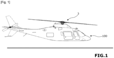
- FIG. 1 we have illustrated a machine which is a helicopter 100 equipped with a power unit.
- the craft may be an aircraft of another type, such as an airplane or a drone.
- the craft may also be a watercraft.
- the helicopter powerplant includes a 3-blade propulsion system that includes two counter-rotating rotors 31, 32. Alternatively, a single rotor may be provided.
- the helicopter may also include an anti-torque rotor or other anti-torque device which may be driven by said power unit or by an independent engine.
- the anti-torque device is not necessary when the craft includes two counter-rotating rotors.
- the blade propulsion system of the craft may include one or more propellers for an airplane or a boat.
- the powertrain comprises a thermal engine 1 configured to enable the propulsion system 3 with blades to be driven as detailed below.
- the thermal engine 1 includes a first thermal engine 1A and a second thermal engine 1B. Each of the first and second thermal engines comprises an output shaft.
- the power of each thermal engine 1A, 1B is for example 150 kW.
- Said powertrain preferably comprises a water cooling system for cooling the heat engines 1A, 1B.
- the powertrain comprises a clutch system 10 which makes it possible to engage any or all of the heat engines 1A, 1B to drive the bladed propulsion system 3.
- the clutch system 10 comprises a clutch 10A and a clutch 10B that can be selectively controlled to enable the first heat engine 1A to be engaged, and/or the second heat engine 1B to be engaged relative to the motion transmission chain between the heat engine 1 and the blade propulsion system 3.
- the clutch system 10 is also configured to allow any or each of the heat engines 1A, 1B to be disengaged relative to the bladed propulsion system 3.
- disengaged with respect to the 3-blade propulsion system means that the thermal engine 1 is decoupled from the force or movement transmission chain which extends between the thermal engine 1 and the 3-blade propulsion system.
- the clutch system 10 of the thermal engine 1 is interposed between the output shafts of the thermal engines 1A, 1B and a motion transmission system 12.
- the motion transmission system 12 is configured to transmit the rotational motion of one or each of said heat engines to a shaft 13, called the output shaft of the heat engine 1.
- the system 12 comprises, for example, a set of gears, or a set of wheel and belt or chain.
- the output shaft 13 is coupled or coupleable to the bladed propulsion system 3 via a motion transmission mechanism presented below.
- the transmission mechanism comprises a speed reduction system which comprises a gear train 21 located between the output shaft 13 of the thermal motor 1 and the input of the electric motor 2.
- the gear train comprises an input shaft 13 and satellites carried by the input shafts of the electric motor 2.
- the transmission mechanism also comprises a transmission system 23 arranged at the output of the electric motor 2 and configured to transmit the rotational movement of the electric motor 2 (which comprises several electric motors in the example illustrated in the figures) to a shaft, called the output shaft 26 of the electric motor.
- a transmission system 23 arranged at the output of the electric motor 2 and configured to transmit the rotational movement of the electric motor 2 (which comprises several electric motors in the example illustrated in the figures) to a shaft, called the output shaft 26 of the electric motor.
- the output shaft 26 is preferably coaxial with the output shaft 13.
- the transmission system 23 forms a reduction (for example of a ratio equal to approximately 1.4) which, with the output shaft 26, makes it possible to drive a speed reduction system 5.
- the speed reduction system 5 comprises an epicyclic gear train 5 whose reduction ratio is for example equal to approximately 3.
- the epicyclic gear train 5 is located between the output shaft 26 of the electric motor 2 and an input shaft A3 of the bladed propulsion system 3.
- the powertrain also includes an electric motor 2 configured to drive the bladed propulsion system 3.
- An electric power supply system 4 comprises a battery 40 for powering the electric motor 2.
- the battery 40 can comprise a set of batteries.
- the electrical power supply system 4 also includes an electrical management system 41, 42 which includes a high-voltage box 41 and a controller 42.
- the high-voltage box 41 makes it possible to open or close the power circuit between the battery 40 and the electric motor 2.
- the controller 42 allows the current supplied by the battery 40 or produced by the electric motor 2 to be processed when it operates as a generator.
- the electric motor 2 has several electric motors 201, 202, preferably distributed regularly around a central axis.
- the electric motor comprises three motors distributed at 120° around an imaginary axis coaxial with the output axis 26.
- the electric motor comprises three motors distributed at 120° around an imaginary axis coaxial with the output axis 26.
- only two motors are shown but a third is present.
- the power of the electric motor 2 is 180 kW, with preferably 60 kW per electric motor 2.
- Each electric motor 201, 202 has an input shaft coupled to the reduction system 21 and an output shaft coupled to the output transmission system 23.
- Each electric motor 201, 202 comprises a clutch release system allowing, for example in the event of a breakdown of said electric motor, to mechanically isolate said electric motor from the other electric motor(s).
- the clutch release system may be a clutch release system.
- the powertrain comprises a casing in which the electric motor 2 is housed. Openings and/or cavities may be provided in the casing to allow the electric motor 2 to be cooled.
- the bladed propulsion system 3 comprises two bladed rotors 31, 32 which each comprise a vertical rotating shaft A31, A32 provided with blades. Said rotors 31, 32 are configured to, in the rotationally driven state, rotate in opposite directions to each other.
- the input shaft A3 of the 3-blade propulsion system is provided with a conical reduction device 6.
- the conical reduction device 6 comprises a bevel gear with a reduction ratio which is for example of the order of 3.7.
- each shaft A31, A32 of rotor 31, 32 is provided with a conical bearing 316, 326 configured to cooperate with the conical gear 6 carried by the input shaft A3 of the propulsion system 3 with blades.
- the powertrain comprises a control unit for controlling the clutch system 10 of the thermal engine 1 and the power supply system 4 of the electric engine 2.
- the clutches are represented for simplification in the open position.
- the description below specifies the actual configuration, open (disengaged) or closed (engaged), of each of said clutches according to the control method implemented.
- arrows have been added (distinct from the reference arrows) to symbolize the motion transmission chain that is active and, where applicable, the electric current delivered or received by the electrical power supply system.
- the powertrain presented above makes it possible to implement different aircraft control processes by adapting the configuration of the clutches.
- the control unit is configured to allow different powertrain operating configurations to be selected depending on the operations to be performed.
- the control unit controls the engagement of the two heat engines 1A, 1B and supplies the electric motor 2 to drive the bladed propulsion system 3 using the combination of the two heat engines 1A, 1B and the electric motor 2.
- This operating mode illustrated in figure 3 is particularly useful when high power is required, especially during take-off.
- the powertrain thus makes it possible to combine the rotational movement provided by the two thermal engines and the rotational movement provided by the electric motor to drive the blade propulsion system.
- the control unit controls the clutch of the two thermal engines 1A, 1B to drive the electric motor 2, so as to, on the one hand, transmit, via the electric motor 2, the rotational movement of the thermal motor 1 to the blade propulsion system 3, while controlling the power supply system 4 to recharge the battery 40.
- This mode of operation illustrated in the figure 4 can be used when the power requirement for the propulsion system 3 is lower than that which can be provided by the thermal engine 1 and the electric battery 40 needs to be recharged.
- Such a mode of operation of the powertrain makes it possible to use the surplus power of the heat engine 1 to recharge the battery 40 in flight, in particular when the battery has been used for electric propulsion during the take-off phase.
- the motorization 2 in particular the electric motors which compose it in the example illustrated in the figures, has or have a double output at the level of their rotor, which allows them to be a motor and/or generator depending on the operating cases.
- the power provided by the thermal engines 1A, 1B is the main source of propulsion.
- the electric motors are transformed into generators and recharge the battery pack 40 through the converter 42 and the power electronics 41.
- the power supplied is approximately 260 kW for propulsion by the thermal engine and 30 kW for recharging the battery.
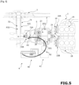
- the control unit controls the disengagement of the two thermal engines 1A, 1B and controls the power supply system 4 to power the electric motor 2.
- the propulsion system 3 with blades is driven using only the electric motorization 2.
- This operating mode illustrated in the figure 5 is particularly useful for a silent landing.
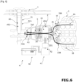
- control unit controls the clutch of the two thermal engines 1A, 1B to transmit the rotational movement of the thermal engine 1 to the propulsion system 3 with blades, but without consuming or generating electric current.
- the rotational motion of the thermal motor 1 is transmitted to the bladed propulsion system 3 via the electric motor 2, which is then passive.
- the electric motor 2 simply serves as a mechanical link in the motion transmission chain between the thermal motor 1 and the propulsion system 3.
- This operating mode illustrated in figure 6 is particularly useful in the event of a power supply system failure.
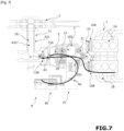
- the control unit controls the disengagement of one 1A of the two heat engines 1A, 1B, for example in the event of a fault in said heat engine 1A, the other heat engine 1B remaining engaged.
- the control unit also controls the power supply system 4 to power the electric motor 2.
- the bladed propulsion system 3 is driven using one of the two heat engines 1A, 1B and preferably the electric motor 2.
- This mode of operation illustrated in the figure 7 is a particularly useful operating mode in the event of a thermal engine failure.
- This operating mode can also be used, for example in a cruise flight configuration, to reduce energy consumption.
- each heat engine 1 can be turned off or can idle while waiting to be used.
- the clutch system is controlled to switch from one configuration to another by a manual or automatic control device comprising the control unit.
- the control device may comprise a human-machine interface connected to the control unit to enable the drivers to control the switch from one configuration to another of the powertrain. It may also be provided that the switch from one configuration to another of the powertrain is triggered automatically by the control unit when predefined conditions are met.
- control unit such as a computer, makes it possible to control a clutch actuation system to control the transition from one configuration to another.
- the control unit may be in the form of a processor and a data memory in which computer instructions executable by said processor are stored, or in the form of a microcontroller.
- the functions and steps described can be implemented using a computer program or via hardware components (e.g. programmable gate arrays).
- the functions and steps performed by the control unit presented above can be performed by instruction sets or computer modules implemented in a processor or controller or can be performed by dedicated electronic components or FPGA or ASIC type components. It is also possible to combine computer parts and electronic parts.
Landscapes
- Engineering & Computer Science (AREA)
- Aviation & Aerospace Engineering (AREA)
- Mechanical Engineering (AREA)
- Chemical & Material Sciences (AREA)
- Combustion & Propulsion (AREA)
- Power Engineering (AREA)
- Sustainable Development (AREA)
- Sustainable Energy (AREA)
- Life Sciences & Earth Sciences (AREA)
- Transportation (AREA)
- Electric Propulsion And Braking For Vehicles (AREA)
- Hybrid Electric Vehicles (AREA)
- Auxiliary Drives, Propulsion Controls, And Safety Devices (AREA)
- Engine Equipment That Uses Special Cycles (AREA)
- Arrangement Of Transmissions (AREA)
- General Engineering & Computer Science (AREA)
Claims (12)
- Maschine (100), wie beispielsweise ein Luftfahrzeug, das mit einem Antriebsaggregat versehen ist, das Antriebsaggregat umfassend:- ein Schaufelradantriebssystem (3),- einen Verbrennungsmotor (1), umfassend einen ersten Verbrennungsmotor (1A) und einen zweiten Verbrennungsmotor (1B), die konfiguriert sind, um den Antrieb des Schaufelradantriebssystems (3) zu ermöglichen,- einen Elektromotorantrieb (2), der konfiguriert ist, um einen Antrieb des Schaufelradantriebssystems (3) zu ermöglichen,- ein Stromversorgungssystem (4), umfassend eine Batterie (40), die es ermöglicht, den Elektromotorantrieb (2) zu versorgen;- ein Kupplungssystem (10), das konfiguriert ist, um ein Einkuppeln des einen oder jedes der Verbrennungsmotoren (1A, 1B) zum Antreiben des Schaufelradantriebssystems (3) zu ermöglichen, wobei das Kupplungssystem (10) auch konfiguriert ist, um ein Auskuppeln des einen oder jedes der Verbrennungsmotoren (1A, 1B) in Bezug auf das Schaufelradantriebssystem (3) zu ermöglichen, wobei der Elektromotorantrieb (2) in Reihe mit dem Verbrennungsmotorantrieb (1) zwischen dem Verbrennungsmotorantrieb (1) und dem Schaufelradsystem (30) angeordnet ist, dadurch gekennzeichnet, dass die Maschine eine Steuereinheit des Kupplungssystems (10) des Verbrennungsmotorantriebs (1) und das Stromversorgungssystem (4) des Elektromotorantriebs (2) umfasst, wobei die Steuereinheit konfiguriert ist, um ein Auskuppeln eines (1A) der zwei Verbrennungsmotoren (1A, 1B) im Fall eines Defekts des Verbrennungsmotors (1A) zu steuern, wobei der andere Verbrennungsmotor (1B) eingekuppelt bleibt, und das Stromversorgungssystem (4) zu steuern, um den Elektromotorantrieb (2) zu versorgen, um das Schaufelradantriebssystem (3) mittels eines der zwei Verbrennungsmotoren (1A, 1B) und des Elektromotorantriebs (2) anzutreiben,und dass die Steuereinheit konfiguriert ist, um zu ermöglichen, die zwei Verbrennungsmotoren (1A, 1B) auszukuppeln und das Stromversorgungssystem (4) zu steuern, um den Elektromotorantrieb (2) zu versorgen, um das Schaufelradantriebssystem (3) nur mittels des Elektromotorantriebs (2) anzutreiben.
- Maschine (100) nach Anspruch 1, dadurch gekennzeichnet, dass die Maschine eine Steuereinheit des Kupplungssystems (10) des Verbrennungsmotors (1) und das Stromversorgungssystem (4) des Elektromotorantriebs (2) umfasst, wobei die Steuereinheit konfiguriert ist, um ein Einkuppeln der zwei Verbrennungsmotoren (1A, 1B) zu ermöglichen, um die Drehbewegung des Verbrennungsmotorantriebs (1) über den Elektromotorantrieb (2) auf das Schaufelradantriebssystem (3) zu übertragen, ohne dass die elektrische Batterie (40) verbraucht oder aufgeladen wird.
- Maschine (100) nach Anspruch 1 oder 2, dadurch gekennzeichnet, dass das Schaufelradantriebssystem (3) zwei Schaufelradrotoren (31, 32) umfasst, die jeweils eine vertikale drehbare Welle (A31, A32) umfassen, die mit Schaufeln versehen ist, wobei die Rotoren (31, 32) konfiguriert sind, um in drehangetriebenem Zustand in entgegengesetzter Richtung zueinander zu drehen.
- Maschine (100) nach einem der vorherigen Ansprüche, dadurch gekennzeichnet, dass, da die Maschine eine Abtriebswelle (13) des Verbrennungsmotorantriebs (1) umfasst, das Kupplungssystem (10) des Verbrennungsmotorantriebs (1) zwischen den Abtriebswellen der Verbrennungsmotoren (1A, 1B) und einem Bewegungsübertragungssystem (12) angeordnet ist, das konfiguriert ist, um die Drehbewegung von einem oder jedem der Verbrennungsmotoren auf die Abtriebswelle (13) des Verbrennungsmotorantriebs (1) zu übertragen.
- Maschine (100) nach einem der vorherigen Ansprüche, dadurch gekennzeichnet, dass, da die Maschine eine Abtriebswelle (26) des Elektromotorantriebs umfasst, das Antriebsaggregat ein Übertragungssystem (23) umfasst, das an dem Ausgang des Elektromotorantriebs (2) angeordnet und konfiguriert ist, um die Drehbewegung des Elektromotorantriebs (2) auf die Abtriebswelle (26) des Elektromotorantriebs zu übertragen.
- Maschine (100) nach einem der vorherigen Ansprüche, dadurch gekennzeichnet, dass die Maschine eine Abtriebswelle (26) des Elektromotorantriebs (2) und eine Eingangswelle (A3) des Schaufelradantriebssystems (3) umfasst, das Antriebsaggregat ein Untersetzungssystem (5), vorzugsweise ein Planetengetriebe, zwischen der Abtriebswelle (26) des Elektromotorantriebs (2) und der Eingangswelle (A3) des Schaufelradantriebssystems (3) umfasst.
- Maschine (100) nach einem der vorherigen Ansprüche, dadurch gekennzeichnet, dass der Elektromotorantrieb (2) mehrere, vorzugsweise drei, Elektromotoren (201, 202) aufweist, die vorzugsweise gleichförmig um eine Mittelachse verteilt sind.
- Maschine (100) nach Anspruch 7, dadurch gekennzeichnet, dass jeder Elektromotor (201, 202) ein Auskupplungssystem, beispielsweise durch Ausrücken, umfasst, das es beispielsweise im Fall eines Ausfalls des Elektromotors ermöglicht, den Elektromotor gegenüber dem oder den anderen Elektromotoren mechanisch zu isolieren.
- Maschine (100) nach einem der vorherigen Ansprüche, dadurch gekennzeichnet, dass die Maschine eine Steuereinheit des Kupplungssystems (10) des Verbrennungsmotorantriebs (1) und das Stromversorgungssystem (4) des Elektromotorantriebs (2) umfasst, wobei die Steuereinheit konfiguriert ist, um ein Einkuppeln der zwei Verbrennungsmotoren (1A, 1B) und eine Versorgung des Elektromotorantriebs (2) zu ermöglichen, um das Schaufelradantriebssystem (3) mittels der Kombination aus den zwei Verbrennungsmotoren (1A, 1B) und dem Elektromotorantrieb (2) anzutreiben.
- Maschine (100) nach einem der vorherigen Ansprüche, dadurch gekennzeichnet, dass die Maschine eine Steuereinheit des Kupplungssystems (10) des Verbrennungsmotorantriebs (1) und des Stromversorgungssystems (4) des Elektromotorantriebs (2) umfasst, wobei die Steuereinheit konfiguriert ist, um ein Einkuppeln der zwei Verbrennungsmotoren (1A, 1B) zum Antreiben des Elektromotorantriebs (2) zu aktivieren, um einerseits über den Elektromotorantrieb (2) die Drehbewegung des Verbrennungsmotorantriebs (1) auf das Schaufelradantriebssystem (3) zu übertragen, während gleichzeitig die Batterie (40) des Stromversorgungssystems (4) aufgeladen wird.
- Maschine (100) nach einem der vorherigen Ansprüche, dadurch gekennzeichnet, dass die Maschine ein Gehäuse umfasst, in dem der Elektromotorantrieb (2) untergebracht ist und in dem Öffnungen und/oder Hohlräume zum Kühlen des Elektromotorantriebs (2) bereitgestellt sind, das Antriebsaggregat umfassend vorzugsweise ein Wasserkühlsystem zum Kühlen der Verbrennungsmotoren (1A, 1B).
- Verfahren zum Steuern einer Maschine (100) nach einem der vorherigen Ansprüche, dadurch gekennzeichnet, dass das Verfahren das Auskuppeln oder das Einkuppeln des einen oder jedes der Verbrennungsmotoren (1A, 1B) in Bezug auf das Schaufelradantriebssystem (3) und/oder das Steuern des Stromversorgungssystems (4) des Elektromotorantriebs umfasst, um den Elektromotorantrieb (2) zu versorgen oder die Batterie (41) aufzuladen.
Applications Claiming Priority (2)
| Application Number | Priority Date | Filing Date | Title |
|---|---|---|---|
| FR1905703A FR3096659B1 (fr) | 2019-05-29 | 2019-05-29 | Engin comprenant un groupe motopropulseur hybride et procédé de pilotage correspondant |
| PCT/FR2020/050892 WO2020240134A1 (fr) | 2019-05-29 | 2020-05-27 | Engin comprenant un groupe motopropulseur hybride et procédé de pilotage correspondant |
Publications (4)
| Publication Number | Publication Date |
|---|---|
| EP3976474A1 EP3976474A1 (de) | 2022-04-06 |
| EP3976474B1 true EP3976474B1 (de) | 2025-02-26 |
| EP3976474C0 EP3976474C0 (de) | 2025-02-26 |
| EP3976474B8 EP3976474B8 (de) | 2025-05-07 |
Family
ID=67742801
Family Applications (1)
| Application Number | Title | Priority Date | Filing Date |
|---|---|---|---|
| EP20743189.1A Active EP3976474B8 (de) | 2019-05-29 | 2020-05-27 | Motor mit hybrider antriebseinheit und entsprechendem kontrollverfahren |
Country Status (10)
| Country | Link |
|---|---|
| US (1) | US11912421B2 (de) |
| EP (1) | EP3976474B8 (de) |
| JP (1) | JP7522768B2 (de) |
| KR (1) | KR20220013552A (de) |
| CN (1) | CN113905949A (de) |
| BR (1) | BR112021023596A2 (de) |
| CA (1) | CA3141176A1 (de) |
| FR (1) | FR3096659B1 (de) |
| IL (1) | IL287892A (de) |
| WO (1) | WO2020240134A1 (de) |
Families Citing this family (4)
| Publication number | Priority date | Publication date | Assignee | Title |
|---|---|---|---|---|
| JP2024507365A (ja) * | 2021-02-21 | 2024-02-19 | ヴェルデゴ エアロ,インコーポレイテッド | 航空宇宙ハイブリッドシステム及びその最適化した構成要素の柔軟なアーキテクチャ |
| EP4310309A1 (de) * | 2022-07-19 | 2024-01-24 | General Electric Company | Hybrid-elektrisches antriebssystem mit einem koppler zum umschalten zwischen betriebsmodi |
| GB2636842A (en) * | 2023-12-22 | 2025-07-02 | Evolito Ltd | Aeronautical propulsion system |
| US12451824B1 (en) | 2024-07-12 | 2025-10-21 | Pratt & Whitney Canada Corp. | Hybrid electric propulsion system with regeneration and method for operating the same |
Family Cites Families (22)
| Publication number | Priority date | Publication date | Assignee | Title |
|---|---|---|---|---|
| US2462825A (en) * | 1944-11-03 | 1949-02-22 | United Aircraft Corp | Automatic declutching means for multiengine drives |
| GB1322948A (en) * | 1970-04-24 | 1973-07-11 | Canadair Ltd | Aircraft yaw control system |
| DE4239639A1 (de) * | 1992-11-23 | 1994-05-26 | Stemme Gmbh & Co Kg | Antriebssystem für ein Flugzeug |
| JP3029976B2 (ja) * | 1995-01-27 | 2000-04-10 | 株式会社コミュータヘリコプタ先進技術研究所 | ヘリコプタの動力伝達装置 |
| US5931757A (en) * | 1998-06-24 | 1999-08-03 | General Motors Corporation | Two-mode, compound-split electro-mechanical vehicular transmission |
| US7413142B2 (en) | 2005-05-31 | 2008-08-19 | Sikorsky Aircraft Corporation | Split torque gearbox for rotary wing aircraft with translational thrust system |
| US8727271B2 (en) | 2008-01-11 | 2014-05-20 | Ival O. Salyer | Aircraft using turbo-electric hybrid propulsion system |
| DE102010021025B4 (de) * | 2010-05-19 | 2014-05-08 | Eads Deutschland Gmbh | Hubschrauber mit Hybridantrieb |
| DE102010021026A1 (de) | 2010-05-19 | 2011-11-24 | Eads Deutschland Gmbh | Hybrides Antriebs- und Energiesystem für Fluggeräte |
| CH703260A1 (de) * | 2010-06-03 | 2011-12-15 | Eugen Gaehwiler | Segelflugzeug. |
| FR2962404B1 (fr) | 2010-07-08 | 2012-07-20 | Eurocopter France | Architecture electrique pour aeronef a voilure tournante a motorisation hybride |
| FR2964948B1 (fr) | 2010-09-16 | 2012-08-31 | Eurocopter France | Aeronef a voilure tournante muni d'un moyen propulsif, et procede applique par ledit aeronef |
| FR2979615B1 (fr) * | 2011-09-04 | 2013-09-20 | Eric Chantriaux | Aeronef equipe d'un groupe electromoteur distribue a roues libres. |
| CA2820254C (en) * | 2012-07-09 | 2020-02-18 | Mcmaster University | Hybrid powertrain system |
| FR3003514B1 (fr) * | 2013-03-25 | 2016-11-18 | Eurocopter France | Aeronef a voilure tournante a motorisation hybride. |
| EP2994386B1 (de) * | 2013-05-06 | 2020-02-19 | Sikorsky Aircraft Corporation | Zusätzliche leistung zur reduzierung eines antriebsaggregats |
| US10850863B2 (en) * | 2014-03-04 | 2020-12-01 | Pratt & Whitney Canada Corp. | System and method for operating a multi-engine aircraft in an auxiliary power unit mode |
| FR3036235B1 (fr) * | 2015-05-15 | 2018-06-01 | Airbus Helicopters | Procede pour activer un moteur electrique d'une installation hybride d'un aeronef multimoteur et un aeronef |
| FR3039614B1 (fr) * | 2015-07-31 | 2018-05-04 | Airbus Helicopters | Installation motrice hybride pour aeronef a voilure tournante bimoteur |
| FI126991B (en) * | 2016-03-01 | 2017-09-15 | Miricle Oy | The floatplane |
| CN108082500A (zh) * | 2018-01-29 | 2018-05-29 | 吉林大学 | 一种固定翼式混合动力飞行器驱动装置及驱动方法 |
| CN108082499B (zh) * | 2018-01-29 | 2023-04-25 | 吉林大学 | 行星式混合动力直升机动力耦合系统及驱动方法 |
-
2019
- 2019-05-29 FR FR1905703A patent/FR3096659B1/fr active Active
-
2020
- 2020-05-27 CA CA3141176A patent/CA3141176A1/fr active Pending
- 2020-05-27 US US17/614,458 patent/US11912421B2/en active Active
- 2020-05-27 EP EP20743189.1A patent/EP3976474B8/de active Active
- 2020-05-27 BR BR112021023596A patent/BR112021023596A2/pt active Search and Examination
- 2020-05-27 WO PCT/FR2020/050892 patent/WO2020240134A1/fr not_active Ceased
- 2020-05-27 KR KR1020217039043A patent/KR20220013552A/ko not_active Ceased
- 2020-05-27 CN CN202080038866.5A patent/CN113905949A/zh active Pending
- 2020-05-27 JP JP2021566999A patent/JP7522768B2/ja active Active
-
2021
- 2021-11-07 IL IL287892A patent/IL287892A/en unknown
Also Published As
| Publication number | Publication date |
|---|---|
| FR3096659A1 (fr) | 2020-12-04 |
| US20220234744A1 (en) | 2022-07-28 |
| WO2020240134A1 (fr) | 2020-12-03 |
| KR20220013552A (ko) | 2022-02-04 |
| BR112021023596A2 (pt) | 2022-01-04 |
| EP3976474B8 (de) | 2025-05-07 |
| IL287892A (en) | 2022-01-01 |
| JP7522768B2 (ja) | 2024-07-25 |
| CN113905949A (zh) | 2022-01-07 |
| EP3976474A1 (de) | 2022-04-06 |
| FR3096659B1 (fr) | 2021-05-07 |
| JP2022534362A (ja) | 2022-07-29 |
| EP3976474C0 (de) | 2025-02-26 |
| CA3141176A1 (fr) | 2020-12-03 |
| US11912421B2 (en) | 2024-02-27 |
Similar Documents
| Publication | Publication Date | Title |
|---|---|---|
| EP3867152B1 (de) | Motor mit hybridantrieb und entsprechendes steuerungsverfahren | |
| EP3976474B1 (de) | Motor mit hybrider antriebseinheit und entsprechendem kontrollverfahren | |
| EP2750969B1 (de) | Luftfahrzeug mit aus mehreren elektromotoren mit freilauf bestehendem antrieb | |
| EP3599140B1 (de) | Verfahren und vorrichtung zur verwaltung der energie einer hybrid-triebwerksanlage eines multirotor-luftfahrzeugs | |
| CA2943486C (fr) | Dispositif d'assistance pour une turbomachine a turbine libre d'un aeronef comprenant au moins deux turbomachines a turbine libre | |
| FR2979614A1 (fr) | Transmission electromagnetique de puissance pour aeronef a voilure tournante ou fixe. | |
| CA2964670C (fr) | Pack amovible de reactivation d'un turbomoteur, architecture d'un systeme propulsif d'un helicoptere multi-moteur equipe d'un tel pack et helicoptere correspondant | |
| EP4244474B1 (de) | Turbomaschine mit freier turbine mit elektrischen maschinen zur unterstützung eines gasgenerators und einer freien turbine | |
| WO2011107718A1 (fr) | Aéronef à voilure tournante ou fixe équipé d'un groupe électromoteur distribué | |
| FR3039614A1 (fr) | Installation motrice hybride pour aeronef a voilure tournante bimoteur | |
| EP4334210B1 (de) | Verbessertes getriebe für hybridflugzeuge | |
| FR3078057A1 (fr) | Architecture de systeme propulsif d'un helicoptere bimoteurs | |
| EP3659922B1 (de) | Ein flugzeug eines modularen typs und ein verfahren zur vorbereitung eines solchen flugzeugs für eine bestimmte mission | |
| WO2024236253A1 (fr) | Ensemble propulsif ameliore pour aeronef hybride multi moteurs | |
| EP4493807A1 (de) | Verbesserte turbomaschine für ein hybridflugzeug | |
| RU2799278C2 (ru) | Аппарат, содержащий гибридную силовую установку, и соответствующий способ управления | |
| WO2019207256A1 (fr) | Systeme de propulsion hybride pour un aeronef | |
| FR2944260A1 (fr) | Systeme de generation de puissance electrique pour aeronef a propulsion arriere | |
| FR3158273A1 (fr) | Dispositif de transmission amélioré pour aéronef hybridé et procédé de désengagement utilisant un tel dispositif | |
| FR3138411A1 (fr) | Ensemble propulsif amélioré pour aéronef hybridé multi moteurs | |
| EP4253248A1 (de) | Propellerflugzeug | |
| FR2944261A1 (fr) | Systeme de generation de puissance electrique pour aeronef a propulsion arriere |
Legal Events
| Date | Code | Title | Description |
|---|---|---|---|
| STAA | Information on the status of an ep patent application or granted ep patent |
Free format text: STATUS: UNKNOWN |
|
| STAA | Information on the status of an ep patent application or granted ep patent |
Free format text: STATUS: THE INTERNATIONAL PUBLICATION HAS BEEN MADE |
|
| PUAI | Public reference made under article 153(3) epc to a published international application that has entered the european phase |
Free format text: ORIGINAL CODE: 0009012 |
|
| STAA | Information on the status of an ep patent application or granted ep patent |
Free format text: STATUS: REQUEST FOR EXAMINATION WAS MADE |
|
| 17P | Request for examination filed |
Effective date: 20211115 |
|
| AK | Designated contracting states |
Kind code of ref document: A1 Designated state(s): AL AT BE BG CH CY CZ DE DK EE ES FI FR GB GR HR HU IE IS IT LI LT LU LV MC MK MT NL NO PL PT RO RS SE SI SK SM TR |
|
| DAV | Request for validation of the european patent (deleted) | ||
| DAX | Request for extension of the european patent (deleted) | ||
| STAA | Information on the status of an ep patent application or granted ep patent |
Free format text: STATUS: EXAMINATION IS IN PROGRESS |
|
| 17Q | First examination report despatched |
Effective date: 20230620 |
|
| GRAP | Despatch of communication of intention to grant a patent |
Free format text: ORIGINAL CODE: EPIDOSNIGR1 |
|
| STAA | Information on the status of an ep patent application or granted ep patent |
Free format text: STATUS: GRANT OF PATENT IS INTENDED |
|
| INTG | Intention to grant announced |
Effective date: 20241009 |
|
| GRAS | Grant fee paid |
Free format text: ORIGINAL CODE: EPIDOSNIGR3 |
|
| GRAA | (expected) grant |
Free format text: ORIGINAL CODE: 0009210 |
|
| STAA | Information on the status of an ep patent application or granted ep patent |
Free format text: STATUS: THE PATENT HAS BEEN GRANTED |
|
| AK | Designated contracting states |
Kind code of ref document: B1 Designated state(s): AL AT BE BG CH CY CZ DE DK EE ES FI FR GB GR HR HU IE IS IT LI LT LU LV MC MK MT NL NO PL PT RO RS SE SI SK SM TR |
|
| REG | Reference to a national code |
Ref country code: GB Ref legal event code: FG4D Free format text: NOT ENGLISH |
|
| REG | Reference to a national code |
Ref country code: CH Ref legal event code: EP |
|
| REG | Reference to a national code |
Ref country code: DE Ref legal event code: R096 Ref document number: 602020046760 Country of ref document: DE |
|
| REG | Reference to a national code |
Ref country code: IE Ref legal event code: FG4D Free format text: LANGUAGE OF EP DOCUMENT: FRENCH |
|
| REG | Reference to a national code |
Ref country code: CH Ref legal event code: PK Free format text: RECTIFICATION B8 |
|
| RAP4 | Party data changed (patent owner data changed or rights of a patent transferred) |
Owner name: VOLTAERO |
|
| U01 | Request for unitary effect filed |
Effective date: 20250325 |
|
| U07 | Unitary effect registered |
Designated state(s): AT BE BG DE DK EE FI FR IT LT LU LV MT NL PT RO SE SI Effective date: 20250401 |
|
| PG25 | Lapsed in a contracting state [announced via postgrant information from national office to epo] |
Ref country code: RS Free format text: LAPSE BECAUSE OF FAILURE TO SUBMIT A TRANSLATION OF THE DESCRIPTION OR TO PAY THE FEE WITHIN THE PRESCRIBED TIME-LIMIT Effective date: 20250526 |
|
| PG25 | Lapsed in a contracting state [announced via postgrant information from national office to epo] |
Ref country code: PL Free format text: LAPSE BECAUSE OF FAILURE TO SUBMIT A TRANSLATION OF THE DESCRIPTION OR TO PAY THE FEE WITHIN THE PRESCRIBED TIME-LIMIT Effective date: 20250226 |
|
| PG25 | Lapsed in a contracting state [announced via postgrant information from national office to epo] |
Ref country code: ES Free format text: LAPSE BECAUSE OF FAILURE TO SUBMIT A TRANSLATION OF THE DESCRIPTION OR TO PAY THE FEE WITHIN THE PRESCRIBED TIME-LIMIT Effective date: 20250226 |
|
| PGFP | Annual fee paid to national office [announced via postgrant information from national office to epo] |
Ref country code: GB Payment date: 20250415 Year of fee payment: 6 |
|
| PG25 | Lapsed in a contracting state [announced via postgrant information from national office to epo] |
Ref country code: NO Free format text: LAPSE BECAUSE OF FAILURE TO SUBMIT A TRANSLATION OF THE DESCRIPTION OR TO PAY THE FEE WITHIN THE PRESCRIBED TIME-LIMIT Effective date: 20250526 Ref country code: IS Free format text: LAPSE BECAUSE OF FAILURE TO SUBMIT A TRANSLATION OF THE DESCRIPTION OR TO PAY THE FEE WITHIN THE PRESCRIBED TIME-LIMIT Effective date: 20250626 |
|
| PG25 | Lapsed in a contracting state [announced via postgrant information from national office to epo] |
Ref country code: HR Free format text: LAPSE BECAUSE OF FAILURE TO SUBMIT A TRANSLATION OF THE DESCRIPTION OR TO PAY THE FEE WITHIN THE PRESCRIBED TIME-LIMIT Effective date: 20250226 |
|
| PG25 | Lapsed in a contracting state [announced via postgrant information from national office to epo] |
Ref country code: GR Free format text: LAPSE BECAUSE OF FAILURE TO SUBMIT A TRANSLATION OF THE DESCRIPTION OR TO PAY THE FEE WITHIN THE PRESCRIBED TIME-LIMIT Effective date: 20250527 |
|
| PGFP | Annual fee paid to national office [announced via postgrant information from national office to epo] |
Ref country code: CH Payment date: 20250601 Year of fee payment: 6 |
|
| U20 | Renewal fee for the european patent with unitary effect paid |
Year of fee payment: 6 Effective date: 20250627 |
|
| PG25 | Lapsed in a contracting state [announced via postgrant information from national office to epo] |
Ref country code: SM Free format text: LAPSE BECAUSE OF FAILURE TO SUBMIT A TRANSLATION OF THE DESCRIPTION OR TO PAY THE FEE WITHIN THE PRESCRIBED TIME-LIMIT Effective date: 20250226 |
|
| PG25 | Lapsed in a contracting state [announced via postgrant information from national office to epo] |
Ref country code: CZ Free format text: LAPSE BECAUSE OF FAILURE TO SUBMIT A TRANSLATION OF THE DESCRIPTION OR TO PAY THE FEE WITHIN THE PRESCRIBED TIME-LIMIT Effective date: 20250226 |
|
| PG25 | Lapsed in a contracting state [announced via postgrant information from national office to epo] |
Ref country code: SK Free format text: LAPSE BECAUSE OF FAILURE TO SUBMIT A TRANSLATION OF THE DESCRIPTION OR TO PAY THE FEE WITHIN THE PRESCRIBED TIME-LIMIT Effective date: 20250226 |