EP3976410B1 - Fuel system with neck support debris mitigation - Google Patents
Fuel system with neck support debris mitigation Download PDFInfo
- Publication number
- EP3976410B1 EP3976410B1 EP20814614.2A EP20814614A EP3976410B1 EP 3976410 B1 EP3976410 B1 EP 3976410B1 EP 20814614 A EP20814614 A EP 20814614A EP 3976410 B1 EP3976410 B1 EP 3976410B1
- Authority
- EP
- European Patent Office
- Prior art keywords
- assembly
- boss
- fuel tank
- bearing
- wiper
- Prior art date
- Legal status (The legal status is an assumption and is not a legal conclusion. Google has not performed a legal analysis and makes no representation as to the accuracy of the status listed.)
- Active
Links
Images


Classifications
-
- B—PERFORMING OPERATIONS; TRANSPORTING
- B60—VEHICLES IN GENERAL
- B60K—ARRANGEMENT OR MOUNTING OF PROPULSION UNITS OR OF TRANSMISSIONS IN VEHICLES; ARRANGEMENT OR MOUNTING OF PLURAL DIVERSE PRIME-MOVERS IN VEHICLES; AUXILIARY DRIVES FOR VEHICLES; INSTRUMENTATION OR DASHBOARDS FOR VEHICLES; ARRANGEMENTS IN CONNECTION WITH COOLING, AIR INTAKE, GAS EXHAUST OR FUEL SUPPLY OF PROPULSION UNITS IN VEHICLES
- B60K15/00—Arrangement in connection with fuel supply of combustion engines or other fuel consuming energy converters, e.g. fuel cells; Mounting or construction of fuel tanks
- B60K15/03—Fuel tanks
- B60K15/063—Arrangement of tanks
- B60K15/067—Mounting of tanks
- B60K15/07—Mounting of tanks of gas tanks
-
- B—PERFORMING OPERATIONS; TRANSPORTING
- B60—VEHICLES IN GENERAL
- B60K—ARRANGEMENT OR MOUNTING OF PROPULSION UNITS OR OF TRANSMISSIONS IN VEHICLES; ARRANGEMENT OR MOUNTING OF PLURAL DIVERSE PRIME-MOVERS IN VEHICLES; AUXILIARY DRIVES FOR VEHICLES; INSTRUMENTATION OR DASHBOARDS FOR VEHICLES; ARRANGEMENTS IN CONNECTION WITH COOLING, AIR INTAKE, GAS EXHAUST OR FUEL SUPPLY OF PROPULSION UNITS IN VEHICLES
- B60K15/00—Arrangement in connection with fuel supply of combustion engines or other fuel consuming energy converters, e.g. fuel cells; Mounting or construction of fuel tanks
- B60K15/03—Fuel tanks
- B60K15/03006—Gas tanks
-
- B—PERFORMING OPERATIONS; TRANSPORTING
- B60—VEHICLES IN GENERAL
- B60K—ARRANGEMENT OR MOUNTING OF PROPULSION UNITS OR OF TRANSMISSIONS IN VEHICLES; ARRANGEMENT OR MOUNTING OF PLURAL DIVERSE PRIME-MOVERS IN VEHICLES; AUXILIARY DRIVES FOR VEHICLES; INSTRUMENTATION OR DASHBOARDS FOR VEHICLES; ARRANGEMENTS IN CONNECTION WITH COOLING, AIR INTAKE, GAS EXHAUST OR FUEL SUPPLY OF PROPULSION UNITS IN VEHICLES
- B60K15/00—Arrangement in connection with fuel supply of combustion engines or other fuel consuming energy converters, e.g. fuel cells; Mounting or construction of fuel tanks
- B60K15/03—Fuel tanks
- B60K15/063—Arrangement of tanks
- B60K15/067—Mounting of tanks
-
- B—PERFORMING OPERATIONS; TRANSPORTING
- B60—VEHICLES IN GENERAL
- B60K—ARRANGEMENT OR MOUNTING OF PROPULSION UNITS OR OF TRANSMISSIONS IN VEHICLES; ARRANGEMENT OR MOUNTING OF PLURAL DIVERSE PRIME-MOVERS IN VEHICLES; AUXILIARY DRIVES FOR VEHICLES; INSTRUMENTATION OR DASHBOARDS FOR VEHICLES; ARRANGEMENTS IN CONNECTION WITH COOLING, AIR INTAKE, GAS EXHAUST OR FUEL SUPPLY OF PROPULSION UNITS IN VEHICLES
- B60K15/00—Arrangement in connection with fuel supply of combustion engines or other fuel consuming energy converters, e.g. fuel cells; Mounting or construction of fuel tanks
- B60K15/03—Fuel tanks
- B60K2015/03118—Multiple tanks, i.e. two or more separate tanks
-
- B—PERFORMING OPERATIONS; TRANSPORTING
- B60—VEHICLES IN GENERAL
- B60K—ARRANGEMENT OR MOUNTING OF PROPULSION UNITS OR OF TRANSMISSIONS IN VEHICLES; ARRANGEMENT OR MOUNTING OF PLURAL DIVERSE PRIME-MOVERS IN VEHICLES; AUXILIARY DRIVES FOR VEHICLES; INSTRUMENTATION OR DASHBOARDS FOR VEHICLES; ARRANGEMENTS IN CONNECTION WITH COOLING, AIR INTAKE, GAS EXHAUST OR FUEL SUPPLY OF PROPULSION UNITS IN VEHICLES
- B60K15/00—Arrangement in connection with fuel supply of combustion engines or other fuel consuming energy converters, e.g. fuel cells; Mounting or construction of fuel tanks
- B60K15/03—Fuel tanks
- B60K15/063—Arrangement of tanks
- B60K2015/0638—Arrangement of tanks the fuel tank is arranged in the rear of the vehicle
Definitions
- This application relates to fuel systems that have fuel tanks supported at a neck portion and to components and sub-assemblies therefor.
- EP1513715 describes structures for securing a fluid containment cylinder at the neck portion of the cylinder that include a mounting frame having a bore disposed therein and a slot disposed orthogonally to the central axis of the bore.
- a fuel system in one embodiment, includes a tank, a mounting assembly, a first bearing block, and a second bearing block.
- the tank has a first boss at one end and a second boss.
- the second boss is located at an end of the tank opposite the first boss.
- the mounting assembly is configured to be coupled to a support.
- the mounting assembly can be directly coupled to a vehicle, such as to a frame rail or can be indirectly coupled to a frame rail or a chassis portion of a vehicle by one or more other brackets or structural members.
- the mounting assembly can be configured to be coupled to a trailer or a stationary storage facility.
- the first bearing block is coupled to the mounting assembly.
- the neck mount support assembly can include a debris exclusion component on an inboard side of the mounting block facing the fuel tank.
- the debris exclusion component can include a cover.
- the cover can be connected to a first side of the mounting block.
- the first side can be the inboard side of the mounting block.
- the cover can be configured to limit debris from entering the interface between the support surface and the boss.
- a debris exclusion component on an inboard side of the neck mount support assembly can include a wiper disposed in mounting block, e.g., between the bearing and the boss.
- the wiper can be used alone or in combination with a cover that can cooperate to exclude debris from entering the interface between the bearing and the boss.
- This application is directed to reducing ingress of debris, such as sand, dust and grit, into an interface that is provided between an outside surface of a neck portion of a fuel tank and a surface applying a load to the outside surface.
- the outside surface may be a cylindrical surface of a boss and the load applying surface may be a bearing or a component of a mounting block or mounting block assembly configured to support at least a portion of the weight of the tank.
- the ingress of such matter can produce wear at the neck portion of the fuel tank. Neck portion wear can lead to accelerated wear of the fuel tank or fuel system in which the tank is integrated, and/or to maintenance concerns of the fuel tank and/or fuel system. The incidence and severity of these outcomes can be reduced or eliminated by embodiments disclosed herein.
- FIGS. 1 and 2 illustrate environments in which embodiments herein can be deployed.
- a fuel system 50 can be coupled with a vehicle 10 to provide the fuel needs therefor.
- a vehicle 10 may refer to any mobile machine or device, including trailers and other towable assemblies, designed or used to transport passengers or cargo, including fuel. Examples of a vehicle may include cars, trucks, buses, trains, ships, boats, aircrafts and other types of vehicles as well as trailer and other component that can be towed by or coupled to any of the foregoing.
- the fuel system 50 could be part of a stationary facility for storage of fuel and/or for refueling a fleet.
- the vehicle 10 in FIG. 1 is a tractor-trailer.
- Classes of trucks that could benefit from the disclosed improvements herein include a light duty trucks (e.g., class 1, class 2 or class 3), medium duty trucks (e.g., class 4, class 5 or class 6), or heavy duty trucks (e.g., class 7 or class 8).
- Passenger vehicles including cars, wagons, vans, buses, high-occupancy vehicles could employ the disclosed improvements as well.
- the vehicle 10 can be any vehicle, as discussed above, but is illustrated as a tractor-trailer with a cab 18 and a detachable portion 22, i.e., the trailer.
- the fuel system 50 is disposed between the cab 18 and the detachable trailer 22 but could be in other locations in other fuel systems.
- the connection to the vehicle 10 can be by way of mounting brackets 51 disposed on a lower portion of the fuel system 50.
- the fuel system 50 can include one or a plurality of fuel tanks 52 disposed in an enclosure 53.
- the fuel tanks 52 may be of any size, capacity, shape and/or weight and may be made of any suitable material.
- the fuel tanks 52 may have a shape that is substantially cylindrical, rectangular, spherical, or the like.
- the fuel tank(s) 52 may be used to store any type(s) of fuel such as gaseous fuels (e.g., compressed natural gas) or a liquid (e.g., diesel).
- gaseous fuels may include hydrogen or hydrogen based gas, hythane, H2CNG, or any other gas.
- the enclosure 53 can be mounted to a structure, e.g., to a support frame of the fuel system 50.
- the fuel system 50 includes a mounting assembly 62 that can include or be supported by a frame 64.
- the mounting assembly 62 can include a block member(s) that receives and retains one or more boss members of the fuel tank 52.
- the mounting assembly 62 can be coupled to the mounting brackets 51, e.g., by the first boss 54 or by other frame members between the frame 64 and the mounting brackets 51.
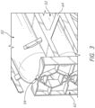
- FIGS. 3 and 3A show details of how the fuel tank 52 can be supported by the mounting assembly 62 and/or the frame 64 and/or block members as discussed further below.
- the fuel tank 52 includes a first end 52A and a second end 52B.
- a cylindrical portion is disposed between the first end 52A and the second end 52B. The cylindrical portion can account for the majority of the volume of the fuel tank 52.
- the ends of the fuel tank 52 can be enclosed by hemispherical dome members at the first end 52A and the second end 52B.
- a first boss 54 can be disposed at the first end 52A.
- a second boss 58 can be disposed at the second end 52B.
- Each boss can have an outer surface, e.g., the first boss 54 can have an outer surface 56 that is exposed and that is coupled to the mounting assembly 62 as discussed below.
- FIG. 3A schematically shows how a fixed bearing block assembly 66 can be integrated into the mounting assembly 62 to support the fuel tank 52 at the second boss 58.
- the fixed bearing block assembly 66 can include a rigid block member 68.
- the fixed bearing block assembly 66 includes a two part assembly that includes two rigid block members 68.
- a first rigid block member 68 is disposed generally above the second boss 58 when applied and a second rigid block member 68 is disposed generally below the second boss 58.
- the two rigid block members 68 can be identical, such that each provides one half of an inner periphery 70 configured to be disposed about the second boss 58.
- the first and second rigid block members 68 have a "C" shape profile when separated.
- the "C" shape refers to one or each of the block members 68 having a convex surface, such as one-half or a portion of the inner periphery 70 and also having external sides disposed about the inner periphery 70 or portion thereof.
- Each block member 68 can have a first side or portion 68A of an outer periphery thereof disposed opposite the inner periphery 70.
- Each block member 68 can have a second 68B and third side 68C disposed opposite of each other and at opposite ends of the first side 68A.
- the two rigid block members 68 can be similar or identical such that each provides a similar or identical outer periphery configured to be secured to the frame 64 or other supporting structure within the mounting brackets 51 of the fuel system 50.
- Apertures in the outer periphery of the rigid block member(s) 68 can allow bolts or other fasteners to secure the two or more rigid block members 68 together.
- the fixed bearing block assembly 66 is a single member with an aperture in a center thereof providing the inner periphery 70.
- the inner periphery 70 can be provided with a boss engaging feature 72, which can be one or a plurality of inner threads 76.
- the inner threads 76 can be configured to mate with the second boss 58 to limit, reduce or eliminate relative movement between the second boss 58 and the fixed bearing block assembly 66.
- the second boss 58 comprises one or a plurality of outer threads 74 that can mate with the boss engaging feature 72, e.g., with the inner threads 76.
- the inner threads 76 are female threads and the outer threads 74 are male threads.
- the inner threads 76 are male threads and the outer threads 74 are female threads.
- the shape and dimensions (e.g., diameter, length) of the inner periphery 70 may be configured to secure or protect the second boss 58.
- the shape of the inner periphery 70 may also be circular.
- the cross-intersection of the second boss 58 is a rectangle and the shape of the inner periphery 70 may resemble a rectangle.
- a first bearing block assembly 90 is provided that is configured to permit some movement between the first boss 54 and an inner periphery 96 configured to be disposed around the first boss 54.
- the inner periphery 96 provides a bearing support space for supporting a bearing which actually contacts the first boss 54 as discussed further below.
- the first bearing block assembly 90 can be configured to be supported in the enclosure 53, e.g., being coupled with the mounting brackets 51 directly or through the frame 64.
- FIG. 3A shows that the first bearing block assembly 90 can include a first block portion 92A and a second block portion 92B.
- the block portions 92A, 92B can be separable in a manner similar to the rigid block member 68 of the fixed bearing block assembly 66.
- the first block portion 92A can be lifted off of the second block portion 92B to provide access to an inner periphery 96 of the block portions 92A, 92B.
- the inner periphery 96 can be shaped and sized (e.g., diameter, length) in a variety of different ways.
- the inner periphery 96 can be circular, triangular, rectangular, pentagonal, hexagonal and octagonal.
- the inner periphery 96 can be shaped in many other configurations other than those previously listed.
- a bearing assembly 100 can be placed in the inner periphery 96 to provide support for the first boss 54.
- a second bearing assembly 100 similar to the first bearing assembly 100 can be provided on the second boss 58.
- the first bearing assembly 100 can be secured in the inner periphery 96 in any suitable manner, such as by being received in a channel therein.
- the bearing assembly 100 can be secured in place by a fastener, pin and key, latch, or other connector.
- the bearing assembly can be secured in place through a more permanent method, such as through welding or bonding.
- the shape and dimensions (e.g., diameter, length) of the bearing assembly 100 may be configured to secure to the inner periphery 96.
- the shape of the bearing assembly 100 may resemble a circle.
- the shape of the bearing assembly 100 may resemble a rectangle.
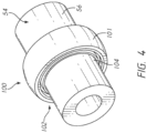
- FIG. 4 shows that the first bearing assembly 100 is shown positioned over the first boss 54.
- the first bearing assembly 100 can be seen to have a convex outer surface 101.
- the convex outer surface 101 can be convex in direction seen in a cross-section transverse, e.g., perpendicular to the opening through the first bearing assembly 100, as shown in FIG. 7 .
- the convex surface can be received in a corresponding concave channel formed in the inner periphery 96 of the first bearing block assembly 90.
- FIG. 4 shows that a first support connection 102 is provided between the outer surface 56 of the first boss 54 and a first inner portion 104 of the first bearing assembly 100.
- FIGS. 5-7 show the first bearing assembly 100 in more detail.
- the first bearing assembly 100 includes an aperture at the first inner portion 104.
- the aperture is sized to receive the outer surface 56 of the first boss 54.
- the aperture can allow a sliding connection to be formed in the first inner portion 104.
- the first inner portion 104 can include a first tank support surface 108.
- the first tank support surface 108 is configured for sliding support of the first boss 54 of the fuel tank 52 at an interface there between.
- the first tank support surface 108 can be a generally flat surface, e.g., forming a cylindrical portion that can be larger than the outer diameter of the outer surface 56 of the first boss 54.
- the first tank support surface 108 can be smooth, with a surface roughness value of anywhere between 0.025 micrometers to 100 micrometers, including about 0.05, 0.1, 0.2, 0.4, 0.8, 1.6, 3.2, 6.3, 12.5, 25, 50, and 100 micrometers.
- the first tank support surface 108 contains bearings, such as a sleeve bearing, ball bearings or another suitable bearing. These bearings can be arranged in a ring or sleeve pattern on the first tank support surface 108.
- the first tank support surface 108 can at least, in part, define a space 110 that is inward of the first tank support surface 108.
- the space 110 can be disposed between the first tank support surface 108 and the outer surface 56 of the first boss 54.
- the space 110 can be or can include a portion of an interface between the fuel tank 52 and the first bearing block assembly 90.
- the space 110 can benefit from the addition of a mechanism to exclude dirt, debris or other matter from the interface. By excluding such matter, the first bearing block assembly 90 and the fuel system 50 can have a longer service life, particularly in dirty environments in which heavy duty vehicles are used.
- the first bearing assembly 100 includes a wiper 112.
- the wiper 112 can be a first wiper 112 where the first bearing assembly 100 also includes a second wiper 130.
- the first wiper 112 can be an inboard wiper, e.g., one that is positioned between the space 110 and the cylindrical portion of the fuel tank 52.
- the first wiper 112 can be an outboard wiper, e.g., one that is positioned such that the block portions 92A, 92B are disposed between the first wiper 112 and the cylindrical portion of the fuel tank 52.
- the first wiper 112 can be outboard in the sense of being more laterally located on the fuel system 50.
- the first wiper 112 and/or the second wiper 130 can be integrated into the first bearing assembly 100 in convenient manner such that they can be installed together with the first tank support surface 108, which is the surface that the outer surface 56 of the first boss 54 can rest upon.
- the first bearing assembly 100 includes a ring member 100A that extends between the convex outer surface 101 and the first tank support surface 108.
- the ring member 100A can include a continuous monolithic structure from the convex outer surface 101 to the first tank support surface 108.
- the ring member 100A can be formed of a strong, substantially incompressible material.
- the ring member 100A can include a low friction material, at least adjacent to or at the first tank support surface 108.
- Some materials that can form the ring member 100A can include, for instance, metal (e.g., aluminum or steel), metal alloy (e.g., aluminum alloys), carbon fiber reinforced plastic, or a plastic material.
- the ring member 100A can be manufactured using a variety of different materials and methods.
- the ring member 100A may be made by any suitable process, such as, for instance, machining, milling, water jet cutting, laser cutting, stamping, pressing, sheet metal drawing, molding (e.g., injection molding), casting, rapid prototyping using additive manufacturing techniques, or any combination thereof.
- the ring member 100A can provide a first recess 116 disposed on a side surface thereof.
- the first recess 116 can be formed in the material of the ring member of the first bearing assembly 100 between the first tank support surface 108 and a lateral surface of the ring member 100A.
- a lateral surface in this context can be disposed in a plane perpendicular to an axis A through the first bearing assembly 100.
- the first recess 116 can correspond to an annular recess disposed between the material forming the first tank support surface 108 and the lateral edge of the ring member 100A of the first bearing assembly 100.
- the first wiper 112 can be installed in the first recess 116.
- the first wiper 112 has one or more, e.g., two faces that can be secured to the first recess 116. Any suitable approach can be provided to secure the first wiper 112 in the first recess 116.
- an adhesive can be used to secure a first face of the first wiper 112 to a surface of the first recess 116.
- An adhesive can be used to secure a second face of the first wiper 112 to a surface of the first recess 116.
- a free end of the first wiper 112 can be disposed in an opening through the first bearing assembly 100 that includes the space 110 disposed between the first tank support surface 108 and the axis A.
- a free end of the first wiper 112 can be suspended at or adjacent to a lateral face of the ring member 100A of the first bearing assembly 100.
- the free end can comprise a free circumferential edge of the first wiper 112.
- the free end of the first wiper 112 can flare at least partially into the opening within the first bearing assembly 100.
- the free end of the first wiper 112 can flare toward the axis A and away from the first recess 116.
- the first wiper 112 can be resilient in structure or material.
- the first wiper 112 can be made from a material, including rubber, silicone, metal, cork, neoprene, nitrile rubber, fiberglass, PTFE, plastic, or any combination thereof.
- the first wiper 112 can be manufactured by any suitable process, such as, for instance, machining, milling, water jet cutting, laser cutting, stamping, pressing, sheet metal drawing, molding (e.g., injection molding), casting, rapid prototyping using additive manufacturing techniques, or any combination thereof.
- the first wiper 112 can be configured such that a portion thereof, e.g, the free end thereof, can be disposed or urged toward the axis A in at least one configuration.
- the first wiper 112 can include a rubber ring member 120.
- the rubber material of the rubber ring member 120 can be springy or resilient such that upon being compressed the first wiper 112 applies a resisting force against the structure compressing the rubber ring member 120.
- the rubber ring member 120 includes an outer periphery 122 secured in the first recess 116 and an inner periphery 124 disposed toward the axis A.
- the outer periphery 122 can be disposed in a free state 126A toward the axis A by a first amount.
- the outer periphery 122 can be disposed in compressed state 126B toward the axis A by a second amount.
- the second amount can be less than the first amount, as shown in, for example, FIG.
- the first wiper 112 is itself resilient.
- a spring or other resilient member 127 can be disposed between the ring member of the first bearing assembly 100 and the first wiper 112 such that the first wiper 112 can be stiff but the resilient member 127 can act to press the first wiper 112 against the outer surface 56 of the first boss 54.
- the first bearing assembly 100 can include a second wiper 130 in some cases.
- the second wiper 130 can be of a similar configuration as the first wiper 112.
- the second wiper 130 can be a mirror image configuration such that an outer periphery 122 thereof flares toward the axis A.
- the second wiper 130 can include or be configured as a rubber ring member. The material of the rubber ring member can be resilient to press against a portion of the outer surface 56 of the first boss 54 spaced away from the location of the first wiper 112.
- a first bearing assembly 100 with both the first wiper 112 and the second wiper 130 can be equipped to exclude matter, e.g., dirt and grit, from the first support connection 102, e.g., from the space 110 forming the interface between the first boss 54 and the first bearing assembly 100.
- a first bearing assembly 100 with both the first wiper 112 and the second wiper 130 can be equipped to exclude matter from the contact point between the first boss 54 and the supporting structure of the fuel tank 52 within the fuel system 50.
- the first bearing block assembly 90 provides convenience in assembling the fuel system 50 including the first bearing block assembly 90.
- the separability of the first block portion 92A from the second block portion 92B enables the first bearing assembly 100 to be inserted into the inner periphery 96 in the space between the block portions 92A, 92B.
- the first and second block portions 92A, 92B have a "C" shape profile.
- the "C" shape refers to the first and second block portions 92A, 92B having a first side facing away from the inner periphery 96 with a second side and a third side disposed opposite to each other and at opposite ends of the first side, similar to the block members 68 discussed above.
- This structure allows the ring member of the first bearing assembly 100 to be continuous which provides a more rigid structure. A continuous solid structure ring member can be more easily handled and may be more rugged with a longer service life.
- FIG. 3B shows another embodiment of a bearing block assembly 190 that provides other advantages.
- the assembly of FIG. 3B can be the same as the assembly of FIG. 3A except as described differently below.
- the first bearing block assembly 190 has a monolithic block component 192.
- the fuel system 50 can be formed by including the first bearing block assembly 190, e.g., by supporting the first bearing block assembly 190 with the frame 64.
- the block component 192 can include an outer periphery 194 coupled to the frame 64.
- the block component 192 can include an inner periphery 196 configured to be disposed around the first boss 54.
- the inner periphery 196 can be sized to surround the outer surface 56 of the first boss 54 while also providing a space for a support connection 200.
- the support connection 200 can include a first inner portion 204 that can comprise an assembly.
- the first inner portion 204 can include a bearing assembly 197 that can include a ring member 199 that has a seam 198 that facilitates placement of the first inner portion 204 within the inner periphery 196.
- the inner periphery 196 can include a concave channel that can receive a convex outer surface of the ring member 199 of the bearing assembly 197.
- the convex outer surface can be similar to the convex outer surface 101 of the first bearing assembly 100.
- the convex outer surface can be split at least at one location such that the ring member 199 of the bearing assembly 197 can be inserted into the inner periphery 196.
- the bearing assembly 197 can include one or more of the first wiper 112 and the second wiper 130.
- FIG. 3B shows that ring member 199 can be coupled with both the first wiper 112 and the second wiper 130.
- the integration of the first wiper 112 and/or the second wiper 130 into the ring member 199 of the bearing assembly 197 can be similar to that of the first bearing assembly 100.
- one or more of the first recess 116 and the second recess 134 can be provided in the ring member 199.
- the first wiper 112 and/or the second wiper 130 can be coupled with the recesses in a suitable manner, e.g., by an adhesive connection to one or more surfaces of the recesses.
- the first bearing block assembly 190 can be incorporated into fuel system assembly similar to the fuel system 50.
- the continuous uninterrupted configuration of the block component 192 provides more rigid support for the first boss 54 in some configurations.
- the assembly of the fuel system 50 including the first bearing block assembly 190 is simplified in not requiring the connection of two separate block components.
- the fuel system 50 includes a bellows assembly 500.
- a bellows assembly 500 can include two clamps 502 and a sheath or cover 504. The cover 504 extends from one clamp 502 to the other, forming a hollow center 506.
- the clamp 502 can attach the bellows assembly 500 to the fuel tank 52 and the bearing block 66, 90, 190.
- the clamps 502 attach the bellows assembly 500 to the fuel tank 52 or bearing block 66, 90, 190 by exerting a clamping force at a connecting point 508.
- the connecting point 508 can be a ferrule or lip on the fuel tank 52 and/or bearing block 66, 90, 190.
- the clamps 502 connect directly to the first or second boss 54, 58.
- the bellows assembly 500 can simultaneously connected to two connecting points 508, such as the connecting point 508 attached to fuel tank 52 and the connecting point 508 attached to the bearing block 66, 90, 190.
- the cover 504 covers a section of the first boss 54 that extends between the fuel tank 52 and the bearing block 66, 90, 190.
- the bellows assembly 500 includes two latches instead of two clamps 502.
- the clamps 502 are configured as ratcheting members, similar to a hose clamp.
- the cover 504 is made from flexible material, such as natural or synthetic fabric, rubber, silicone, neoprene, nitrile rubber, PTFE, or other plastics. This flexible material allows the cover 504 to expand or contract, which thus increases or decreases the overall length of the cover 504.
- the cover 504 has a ribbed outer surface. The ribbed outer surface allows the hollow center 506 to maintain about a steady inner circumference while the cover 504 expands or contracts.
- the fuel system 50 can include two or more sets of bellows assemblies 500, e.g., one for each boss 54, 58. In some embodiments, the fuel system 50 can include one of bellow assembly 500 for a single boss 54, 58. In some embodiments, the bellows assembly 500 is used in combination with a bearing block 66, 90, 190.
- FIGS. 10-12C show another embodiment of a bearing block assembly 600 for use with the fuel system 50.
- the bearing block assembly 600 can be similar to the bearing block assemblies described before.
- the bearing block assembly 600 can permit some movement between the first boss 54 and the bearing block assembly 600, while also reducing the ingress of debris onto the first boss 54.
- the bearing block assembly 600 can exclude ingress of debris from one or both of an outboard and an inboard side.
- the bearing block assembly can include an inner periphery 620, which can be disposed around the first boss 54.
- the inner periphery 620 provides a bearing support space for supporting the first bearing assembly 100, which actually contacts the first boss 54.
- the first bearing assembly 100 includes one or more dust wipers. In variations more or fewer wipers can be provided.
- the bearing block assembly 600 can be provided without any dust wipers in the interface between the boss 54 and the bearing surface of the assembly 100, as shown in FIG. 11 .
- the bearing block assembly 600 can be supported in the enclosure 53.
- the bearing block assembly 600 can be coupled with the mounting brackets 51 directly or through the frame 64.
- the bearing block assembly 600 can include a bearing block 602.
- FIGS. 12A-12C show that the bearing block 602 can include a first block portion 602A and a second block portion 602B.
- the block portions 602A, 602B can be separable in a manner similar to the rigid block member 68 of the fixed bearing block assembly 66 and the first bearing block 92 of first bearing block assembly 90.
- the first block portion 602A can be lifted off of or separated from the second block portion 602B to provide access to an inner periphery 620 of the block portions 602A, 602B.
- the inner periphery 620 can be shaped and sized (e.g., diameter, length) in a variety of different ways.
- the inner periphery 620 can be circular, triangular, rectangular, pentagonal, hexagonal and octagonal.
- the inner periphery 620 can be shaped in many other configurations other than those previously listed.
- a bearing assembly 100 can be placed in the inner periphery 620 to provide support for the first boss 54.
- the bearing assembly 100 can be secured in the inner periphery 620 in any suitable manner, such as by being received in a channel therein.
- the bearing assembly 100 can be secured in place by a fastener, pin and key, latch, or other connector.
- the bearing assembly can be secured in place through a more permanent method, such as through welding or bonding.
- the shape and dimensions (e.g., diameter, length) of the bearing assembly 100 may be configured to secure to the inner periphery 602.
- the shape of the bearing assembly 100 may resemble a circle.
- the shape of the outer periphery of the bearing assembly 100 may resemble a rectangle.
- the bearing block 602 can include a ridge 622.
- the ridge 622 can be formed on one or two sides of the first block portion 602A and the second block portion 602B.
- the ridge 622 can form a raised surface on a side of the bearing block 602.
- the ridge 622 can be used to connect the bearing block 602 to a structure or can be used to secure a structure to the bearing block 602.
- a clamp 608 can be placed around the outer edge of the ridge 622 to hold a cover 606 in place.
- the ridge 622 can include an annular projection on a first or inboard side of the bearing block 620.
- the ridge 622 can provide a peripheral, e.g., a circumferential, surface 623 providing an area upon which a clamp can apply a compression force.
- a peripheral surface 623 is illustrated as flat, a concave recess can be provided in the peripheral surface 623 to receive or partly receive a portion of a clamp.
- the bearing block 602 can include one or more fastener holes 626.
- the fastener holes 626 can be formed on one or more sides of the first block portion 602A and the second block portion 602B.
- the fastener holes 626 can be disposed on an outboard side, as shown.
- fastener holes 626 can be disposed on inboard and outboard sides of the bearing block portions 602A, 602B.
- the fastener holes 626 are through holes that extend through the block portions 602A, 602B. In other embodiments, the fastener holes 626 do not extend completely through the block portions 602A, 602B.
- the fastener holes 626 can be used to connect the bearing block 602 to a structure or can be used to secure a structure to the bearing block 602.
- the fastener holes 626 can receive fasteners 612 to secure the end cap 604 to the bearing block 602.
- the fastener holes 626 can be used to secure the cover 606 in some embodiments.
- the bearing block 602 can include through holes 624.
- the through holes 624 can be formed on one side of the first block portion 602A and the second block portion 602B.
- the through holes 624 can be used connect the bearing block 602 to a structure.
- the through holes 624 can be used connect the bearing block 602 to the mounting brackets 51 directly or the frame 64.
- the bearing block 602 provides convenience in assembling the fuel system 50 including the bearing block assembly 600.
- the separability of the first block portion 602A from the second block portion 602B enables the first bearing assembly 100 to be inserted into the inner periphery 620 in the space between the block portions 602A, 602B.
- the first and second block portions 602A, 602B can have a "C" shape profile.
- the "C" shape refers to the first and second block portions 602A, 602B having a first side facing away from the inner periphery 620A with a second side and a third side disposed opposite to each other and at opposite ends of the first side, similar to the block members 68 and 92 discussed above.
- This structure allows a ring member or other portion or all of the first bearing assembly 100 to be continuous which provides a more rigid structure.
- a continuous solid structure ring member can be more easily handled and may be more rugged with a longer service life.
- FIGS. 10 and 11 show further details of the endcap 604 and the integration thereof into the bearing block assembly 600.
- the end cap 604 can have a cylindrical shape with an open-ended chamber.
- the end cap 604 can have an opening on one side of the end cap 604 that leads to the chamber.
- This open-ended chamber allows for the end cap 604 to be placed around objects.
- the end cap 604 can be placed around the first boss 54.
- This open-ended chamber can have a closed end at an inside surface 607 opposite to the opening to mitigate or exclude dust or debris from entering the space in the chamber.
- the end cap 604 can have one or more fastener holes, which allow for the end cap 604 to connect to a structure or can be used to secure a structure to the end cap 604.
- the end cap 604 can be fastened to a side of the bearing block 602.
- the fastener holes can be disposed on a radially outwardly extending annular flange 605.
- An inboard side of the flange 605 can make contact with outside surfaces of the block portions 602A, 602B.
- the bearing block assembly 600 can include a cover 606.
- the cover 606 can be a material that can be placed over other components.
- the cover 606 can have a hollowed center, which allows for the cover 606 to be slid over other components.
- the cover 606 can be slid or placed over the first boss 54.
- the cover 606 can be made from a flexible material, such as natural or synthetic fabric, rubber, silicone, neoprene, nitrile rubber, PTFE, or other plastics. This flexible material allows the cover 606 to expand or contract, which thus increases or decreases the overall length of the cover 606.
- the cover 606 can be connected to other components through a clamp 608.
- the cover 606 can be connected to the bearing block 602 and the first boss 54 of the fuel tank 52 with two clamps 608.
- a first clamp 608 can be disposed on the bearing block 602, e.g., by compression onto the peripheral surface 623, and a second clamp 608 can be disposed on a surface 625 of the first boss 54.
- the first and second clamps 608 can have the same configuration, e.g., similar to hose clamps in one embodiment.
- the bearing block assembly 600 can be used to prevent the ingress of dust and other debris into the inner periphery 620 and the first boss 54.
- the bearing block 602, end cap 604, and cover 606 can be used to envelop most of, or all of, the outer surface 56 of the first boss 54.
- the cover 606 can be used for coverage of the first boss 54 between the connecting point 508 of the fuel tank and the connecting point to bearing block 602, while the end cap can be used to for coverage of the first boss 54 between the bearing block 602 and the end of the first boss 54.
- the bearing block assembly 600 can greatly limit the amount of debris that can enter into the inner periphery 620. This coverage can also keep the outer surface 56 of the first boss 54 free from debris.
- the use of wipers 112 in the interface between the bearing block 602 and the boss 54 can further exclude debris from this interface.
- the bearing block assembly 600 can permit some movement between the bearing block assembly 600 and the first boss 54.
- the fuel tank 52 can be somewhat expanded, e.g., elongated, when under pressure in part due to the materials used to form the fuel tank 52.
- the cover 606 can expand, e.g., elongate, or contract, e.g., foreshorten, along with the fuel tank 52, which allows for cover 606 to maintain its coverage over the first boss 54.
- the cover 606 can include a bellows-type member, as discussed above in connection with FIGS.
- the chamber of the endcap 604 can be sized so as to allow for the fuel tank 52 to expand without the inside surface 607 of the endcap contacting the first boss 54.
- the inside surface 607 of the endcap 604 can be spaced away from the end of the first boss 54 or a plug 610 enclosing an access passage in the boss 54 at or beyond the expected travel distance of the first boss 54 or plug 610.
- the bearing block assembly 600 can maintain its coverage of the first boss 54 while the fuel tank 52 expands or contracts without interfering with the expected expansion and contraction of the boss 54 and/or the plug 610.
- the terms “generally parallel” and “substantially parallel” refer to a value, amount, or characteristic that departs from exactly parallel by less than or equal to 15 degrees, 10 degrees, 5 degrees, 3 degrees, 1 degree, or 0.1 degree.
Landscapes
- Engineering & Computer Science (AREA)
- Life Sciences & Earth Sciences (AREA)
- Sustainable Development (AREA)
- Sustainable Energy (AREA)
- Chemical & Material Sciences (AREA)
- Combustion & Propulsion (AREA)
- Transportation (AREA)
- Mechanical Engineering (AREA)
- Cooling, Air Intake And Gas Exhaust, And Fuel Tank Arrangements In Propulsion Units (AREA)
- Details Of Rigid Or Semi-Rigid Containers (AREA)
Description
- This application relates to fuel systems that have fuel tanks supported at a neck portion and to components and sub-assemblies therefor.
- Compressed natural gas (CNG) is an alternative fuel that provides many advantages. CNG fuels burn cleaner than other combustion fuels. CNG also can be more cost effective.
- CNG fuel systems can come in several forms. One form employs a Type IV fuel tank constructed with a polymeric liner. Carbon fiber wrapped around the liner can reinforce the liner, to produce a fuel tank strong enough for use on heavy-duty trucks and other vehicles. The fuel tank can have a boss disposed at one or more ends for sealing the end portion(s) of the fuel tank. The boss can provide access to the fuel tank for filling and dispensing the fuel contained therein. The fuel tank can be integrated into a fuel system that includes a frame to support the fuel tank. The frame can support the fuel tank on a side or lateral portion of a vehicle, behind the cab of the vehicle, on a rooftop of the vehicle, or at another location. Some fuel tanks can be supported at one or both ends at the bosses.
-
DE 102015009032 describes a floating bearing for a compressed gas container with at least one cylindrical receiving area for the floating bearing, with a bearing shell which is designed to enclose the receiving area with an inner surface, which is movable in the axial direction relative to the receiving area, and which has a spherical outer surface, with a bearing block and a receptacle between the bearing block and the outer surface of the bearing shell, wherein an inner surface of the receptacle has a shape corresponding to the spherical outer surface of the bearing shell. -
EP1513715 describes structures for securing a fluid containment cylinder at the neck portion of the cylinder that include a mounting frame having a bore disposed therein and a slot disposed orthogonally to the central axis of the bore. - The invention is defined by the appended claims.
- Fuel tanks that are supported at one or more bosses can be subject to wear at the interface between the boss and the support. For example, in some cases it is observed that the fuel tank can expand and contract by small but significant amounts in a lengthwise direction. The expansion and contraction can be due to conditions such as the level of pressure in the tank, the temperature of the tank, the ambient temperature and other surrounding environmental conditions, or loading of the fuel tank. The expansion and contraction can cause relative sliding motion that can result in wear on the fuel tank, e.g., on a surface of the boss. While the fuel tank can be configured for a long service life accounting for wear, it would be an advantage to reduce fuel tank wear for a number of reasons, such as reducing maintenance and repair costs and preventing sudden material failure.
- In one embodiment, a fuel system is provided that includes a tank, a mounting assembly, a first bearing block, and a second bearing block. The tank has a first boss at one end and a second boss. The second boss is located at an end of the tank opposite the first boss. The mounting assembly is configured to be coupled to a support. For example, the mounting assembly can be directly coupled to a vehicle, such as to a frame rail or can be indirectly coupled to a frame rail or a chassis portion of a vehicle by one or more other brackets or structural members. The mounting assembly can be configured to be coupled to a trailer or a stationary storage facility. The first bearing block is coupled to the mounting assembly. The first bearing block has a first inner portion comprising a first tank support surface and a wiper disposed adjacent to the first tank support surface. The second bearing block is coupled to the mounting assembly. The second bearing block has a second inner portion comprising a second tank support surface. The first bearing block being coupled to an outer surface of the first boss at the first tank support surface to form a first support connection. The second bearing block being coupled to an outer surface of the second boss at the second tank support surface to form a second support connection. The first and second support connections support the tank on the mounting assembly. The first bearing block allow the first boss to move relative to the first tank support surface while the tank is coupled to the mounting assembly. The wiper prevents debris from entering a space disposed between the first tank support surface and the first boss when the first boss move relative to the first support surface.
- In another embodiment, a fuel system is provided that includes a mounting block assembly configured to support an end of a fuel tank. The end of the fuel tank has a boss. The mounting block assembly has a first portion and a second portion. The second portion is separable from the first portion. The first portion and the second portion enclose a space configured to receive the boss of the fuel tank. The fuel system also includes a bearing disposed in the space. The bearing has a support surface configured for sliding support of the boss of the fuel tank at an interface between the first portion and the second portion of the mounting block assembly. The bearing has an inboard facing surface. The inboard facing surface faces the end of the fuel tank when the fuel tank is supported by the mounting block assembly. The bearing has a wiper disposed adjacent to the support surface.
- In another embodiment, a neck mount support assembly is provided that includes a mounting block assembly that is configured to support an end of a fuel tank. The end of the fuel tank has a boss. The mounting block assembly has a first portion and a second portion separable from the first portion. The first portion and the second portion enclose a space configured to receive the boss of the fuel tank. A bearing is disposed in the space. The bearing has a support surface configured for sliding support of the boss of the fuel tank at an interface. The mounting block has a wiper disposed adjacent to the support surface of the bearing. The wiper is configured to limit debris from entering the interface between the support surface and the boss.
- In another embodiment a neck mount support assembly is provided that includes a mounting block and an end cap. The mounting block can be configured to support an end of a fuel tank, e.g., an end having a boss. The mounting block has a first portion and a second portion separable from the first portion. The first portion and the second portion enclose a bearing support space configured to receive the boss of the fuel tank. A bearing can be or is disposed in the bearing support space. The bearing has a support surface configured to support the boss of the fuel tank at an interface. The endcap can be connected to an outboard side of the mounting block opposite the side of the mounting block configured to face the fuel tank. The endcap can be configured to limit debris from entering the interface between the support surface and the boss.
- In one variation, the neck mount support assembly can include a debris exclusion component on an inboard side of the mounting block facing the fuel tank. The debris exclusion component can include a cover. The cover can be connected to a first side of the mounting block. The first side can be the inboard side of the mounting block. The cover can be configured to limit debris from entering the interface between the support surface and the boss.
- A cover, if provided, can span a length of the boss between the mounting block and the fuel tank enclosure. The cover can be secured to an outer surface of the fuel tank assembly.
- A debris exclusion component on an inboard side of the neck mount support assembly can include a wiper disposed in mounting block, e.g., between the bearing and the boss. The wiper can be used alone or in combination with a cover that can cooperate to exclude debris from entering the interface between the bearing and the boss.
- The abovementioned and other features of the invention disclosed herein are described below with reference to the drawings of the preferred embodiments. The illustrated embodiments are intended to illustrate, but not to limit the invention. The drawings contain the following figures.
-
FIG. 1 is a perspective view of a tractor-trailer with a cab that has a fuel system disposed behind the cab. -
FIG. 2 is a perspective view of a fuel system mountable behind the cab of the tractor-trailer shown inFIG. 1 , the fuel system having one or more fuel tanks disposed therein. -
FIG. 3 is a detail view showing a mounting system for supporting neck portions of fuel tanks. -
FIGS. 3A-3B are schematic views of fuel tank and mounting block assemblies that can be used to support the fuel tank while excluding debris from the assemblies. -
FIG. 4 is a perspective view illustrating an assembly including a neck boss component and a bearing assembly according to one example. -
FIG. 5 is a perspective view of one embodiment of a bearing assembly that can be incorporated into a mounting block assembly; -
FIG. 6 is a side view of the bearing assembly ofFIG. 5 . -
FIG. 7 is a cross-sectional view of a bearing assembly taken at section plane 7-7 inFIG. 6 . -
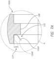
FIG. 7A is a detail view of the cross-sectional view ofFIG. 7 . -
FIG. 8 is a schematic views of a fuel tank and mounting block assembly that can be used to support the fuel tank while excluding debris from the assembly. -
FIG. 9 is a detail view of a portion of a modified embodiment of the fuel tank and mounting block assembly ofFIG. 8 . -
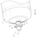
FIG. 10 is a perspective view of an embodiment of a fuel tank and mounting block assembly that can mitigate and even exclude debris from an interface between a fuel tank boss and a bearing of a mounting block assembly. -
FIG. 11 is a cross-sectional view of a neck mount support assembly that includes an end cap and a cover to mitigate debris ingress from the outboard and inboard sides respectively. -
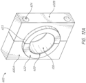
FIG. 12A is a perspective view of an inboard side of one embodiment of a mounting block. -
FIG. 12B is a perspective view of an outboard side of one embodiment of a mounting block. -
FIG. 12C is a perspective view of an inboard side of a portion of the mounting block shown inFIG. 12A . - This application is directed to reducing ingress of debris, such as sand, dust and grit, into an interface that is provided between an outside surface of a neck portion of a fuel tank and a surface applying a load to the outside surface. The outside surface may be a cylindrical surface of a boss and the load applying surface may be a bearing or a component of a mounting block or mounting block assembly configured to support at least a portion of the weight of the tank. The ingress of such matter can produce wear at the neck portion of the fuel tank. Neck portion wear can lead to accelerated wear of the fuel tank or fuel system in which the tank is integrated, and/or to maintenance concerns of the fuel tank and/or fuel system. The incidence and severity of these outcomes can be reduced or eliminated by embodiments disclosed herein.
-
FIGS. 1 and2 illustrate environments in which embodiments herein can be deployed. In one example, afuel system 50 can be coupled with avehicle 10 to provide the fuel needs therefor. In various embodiments, avehicle 10 may refer to any mobile machine or device, including trailers and other towable assemblies, designed or used to transport passengers or cargo, including fuel. Examples of a vehicle may include cars, trucks, buses, trains, ships, boats, aircrafts and other types of vehicles as well as trailer and other component that can be towed by or coupled to any of the foregoing. More generally, thefuel system 50 could be part of a stationary facility for storage of fuel and/or for refueling a fleet. Thevehicle 10 inFIG. 1 is a tractor-trailer. Classes of trucks that could benefit from the disclosed improvements herein include a light duty trucks (e.g.,class 1, class 2 or class 3), medium duty trucks (e.g.,class 4, class 5 or class 6), or heavy duty trucks (e.g.,class 7 or class 8). Passenger vehicles, including cars, wagons, vans, buses, high-occupancy vehicles could employ the disclosed improvements as well. Thevehicle 10 can be any vehicle, as discussed above, but is illustrated as a tractor-trailer with acab 18 and adetachable portion 22, i.e., the trailer. Thefuel system 50 is disposed between thecab 18 and thedetachable trailer 22 but could be in other locations in other fuel systems. The connection to thevehicle 10 can be by way of mountingbrackets 51 disposed on a lower portion of thefuel system 50. Thefuel system 50 can include one or a plurality offuel tanks 52 disposed in anenclosure 53. Thefuel tanks 52 may be of any size, capacity, shape and/or weight and may be made of any suitable material. For example, thefuel tanks 52 may have a shape that is substantially cylindrical, rectangular, spherical, or the like. In addition, the fuel tank(s) 52 may be used to store any type(s) of fuel such as gaseous fuels (e.g., compressed natural gas) or a liquid (e.g., diesel). For example, gaseous fuels may include hydrogen or hydrogen based gas, hythane, H2CNG, or any other gas. Theenclosure 53 can be mounted to a structure, e.g., to a support frame of thefuel system 50. - In one embodiment, the
fuel system 50 includes a mountingassembly 62 that can include or be supported by aframe 64. The mountingassembly 62 can include a block member(s) that receives and retains one or more boss members of thefuel tank 52. The mountingassembly 62 can be coupled to the mountingbrackets 51, e.g., by thefirst boss 54 or by other frame members between theframe 64 and the mountingbrackets 51. -
FIGS. 3 and3A show details of how thefuel tank 52 can be supported by the mountingassembly 62 and/or theframe 64 and/or block members as discussed further below. Thefuel tank 52 includes afirst end 52A and asecond end 52B. A cylindrical portion is disposed between thefirst end 52A and thesecond end 52B. The cylindrical portion can account for the majority of the volume of thefuel tank 52. The ends of thefuel tank 52 can be enclosed by hemispherical dome members at thefirst end 52A and thesecond end 52B. Afirst boss 54 can be disposed at thefirst end 52A. Asecond boss 58 can be disposed at thesecond end 52B. Each boss can have an outer surface, e.g., thefirst boss 54 can have anouter surface 56 that is exposed and that is coupled to the mountingassembly 62 as discussed below. -
FIG. 3A schematically shows how a fixedbearing block assembly 66 can be integrated into the mountingassembly 62 to support thefuel tank 52 at thesecond boss 58. The fixedbearing block assembly 66 can include arigid block member 68. In one embodiment the fixedbearing block assembly 66 includes a two part assembly that includes tworigid block members 68. A firstrigid block member 68 is disposed generally above thesecond boss 58 when applied and a secondrigid block member 68 is disposed generally below thesecond boss 58. The tworigid block members 68 can be identical, such that each provides one half of aninner periphery 70 configured to be disposed about thesecond boss 58. In some embodiments the first and secondrigid block members 68 have a "C" shape profile when separated. The "C" shape refers to one or each of theblock members 68 having a convex surface, such as one-half or a portion of theinner periphery 70 and also having external sides disposed about theinner periphery 70 or portion thereof. Eachblock member 68 can have a first side orportion 68A of an outer periphery thereof disposed opposite theinner periphery 70. Eachblock member 68 can have a second 68B andthird side 68C disposed opposite of each other and at opposite ends of thefirst side 68A. The tworigid block members 68 can be similar or identical such that each provides a similar or identical outer periphery configured to be secured to theframe 64 or other supporting structure within the mountingbrackets 51 of thefuel system 50. Apertures in the outer periphery of the rigid block member(s) 68 can allow bolts or other fasteners to secure the two or morerigid block members 68 together. In another embodiment, the fixedbearing block assembly 66 is a single member with an aperture in a center thereof providing theinner periphery 70. - The
inner periphery 70 can be provided with aboss engaging feature 72, which can be one or a plurality ofinner threads 76. Theinner threads 76 can be configured to mate with thesecond boss 58 to limit, reduce or eliminate relative movement between thesecond boss 58 and the fixedbearing block assembly 66. In one case, thesecond boss 58 comprises one or a plurality ofouter threads 74 that can mate with theboss engaging feature 72, e.g., with theinner threads 76. In one case, theinner threads 76 are female threads and theouter threads 74 are male threads. In another case, theinner threads 76 are male threads and theouter threads 74 are female threads. In various embodiments, the shape and dimensions (e.g., diameter, length) of theinner periphery 70 may be configured to secure or protect thesecond boss 58. For example, where the cross-section of thesecond boss 58 is a circle, the shape of theinner periphery 70 may also be circular. In other embodiments the cross-intersection of thesecond boss 58 is a rectangle and the shape of theinner periphery 70 may resemble a rectangle. - As noted above, the
fuel tank 52 can be somewhat expanded when under pressure in part due to the materials used to form thefuel tank 52. In some cases, a longer lastingfuel system 50 results from permitting thefuel tank 52 to expand while holding thefuel tank 52 in thefuel system 50. In one embodiment, a firstbearing block assembly 90 is provided that is configured to permit some movement between thefirst boss 54 and aninner periphery 96 configured to be disposed around thefirst boss 54. Theinner periphery 96 provides a bearing support space for supporting a bearing which actually contacts thefirst boss 54 as discussed further below. The firstbearing block assembly 90 can be configured to be supported in theenclosure 53, e.g., being coupled with the mountingbrackets 51 directly or through theframe 64. -
FIG. 3A shows that the firstbearing block assembly 90 can include afirst block portion 92A and asecond block portion 92B. Theblock portions rigid block member 68 of the fixedbearing block assembly 66. Thefirst block portion 92A can be lifted off of thesecond block portion 92B to provide access to aninner periphery 96 of theblock portions inner periphery 96 can be shaped and sized (e.g., diameter, length) in a variety of different ways. For instance, theinner periphery 96 can be circular, triangular, rectangular, pentagonal, hexagonal and octagonal. Theinner periphery 96 can be shaped in many other configurations other than those previously listed. A bearingassembly 100 can be placed in theinner periphery 96 to provide support for thefirst boss 54. In some embodiments, asecond bearing assembly 100 similar to thefirst bearing assembly 100 can be provided on thesecond boss 58. Thefirst bearing assembly 100 can be secured in theinner periphery 96 in any suitable manner, such as by being received in a channel therein. In some embodiments, the bearingassembly 100 can be secured in place by a fastener, pin and key, latch, or other connector. In other embodiments, the bearing assembly can be secured in place through a more permanent method, such as through welding or bonding. In various embodiments, the shape and dimensions (e.g., diameter, length) of the bearingassembly 100 may be configured to secure to theinner periphery 96. For example, where the intersection of theinner periphery 96 is a circle, the shape of the bearingassembly 100 may resemble a circle. Where the intersection of theinner periphery 96 is a rectangle, the shape of the bearingassembly 100 may resemble a rectangle. - This connection can be more fully appreciated with reference to
FIG. 4 in which thefirst bearing assembly 100 is shown positioned over thefirst boss 54. Thefirst bearing assembly 100 can be seen to have a convexouter surface 101. The convexouter surface 101 can be convex in direction seen in a cross-section transverse, e.g., perpendicular to the opening through thefirst bearing assembly 100, as shown inFIG. 7 . The convex surface can be received in a corresponding concave channel formed in theinner periphery 96 of the firstbearing block assembly 90.FIG. 4 shows that afirst support connection 102 is provided between theouter surface 56 of thefirst boss 54 and a firstinner portion 104 of thefirst bearing assembly 100. -
FIGS. 5-7 show thefirst bearing assembly 100 in more detail. Thefirst bearing assembly 100 includes an aperture at the firstinner portion 104. The aperture is sized to receive theouter surface 56 of thefirst boss 54. The aperture can allow a sliding connection to be formed in the firstinner portion 104. The firstinner portion 104 can include a firsttank support surface 108. The firsttank support surface 108 is configured for sliding support of thefirst boss 54 of thefuel tank 52 at an interface there between. The firsttank support surface 108 can be a generally flat surface, e.g., forming a cylindrical portion that can be larger than the outer diameter of theouter surface 56 of thefirst boss 54. The firsttank support surface 108 can be smooth, with a surface roughness value of anywhere between 0.025 micrometers to 100 micrometers, including about 0.05, 0.1, 0.2, 0.4, 0.8, 1.6, 3.2, 6.3, 12.5, 25, 50, and 100 micrometers. In some embodiments, the firsttank support surface 108 contains bearings, such as a sleeve bearing, ball bearings or another suitable bearing. These bearings can be arranged in a ring or sleeve pattern on the firsttank support surface 108. - The first
tank support surface 108 can at least, in part, define aspace 110 that is inward of the firsttank support surface 108. Thespace 110 can be disposed between the firsttank support surface 108 and theouter surface 56 of thefirst boss 54. Thespace 110 can be or can include a portion of an interface between thefuel tank 52 and the firstbearing block assembly 90. Thespace 110 can benefit from the addition of a mechanism to exclude dirt, debris or other matter from the interface. By excluding such matter, the firstbearing block assembly 90 and thefuel system 50 can have a longer service life, particularly in dirty environments in which heavy duty vehicles are used. - In one embodiment, the
first bearing assembly 100 includes awiper 112. Thewiper 112 can be afirst wiper 112 where thefirst bearing assembly 100 also includes asecond wiper 130. Thefirst wiper 112 can be an inboard wiper, e.g., one that is positioned between thespace 110 and the cylindrical portion of thefuel tank 52. Thefirst wiper 112 can be an outboard wiper, e.g., one that is positioned such that theblock portions first wiper 112 and the cylindrical portion of thefuel tank 52. Thefirst wiper 112 can be outboard in the sense of being more laterally located on thefuel system 50. - The
first wiper 112 and/or thesecond wiper 130 can be integrated into thefirst bearing assembly 100 in convenient manner such that they can be installed together with the firsttank support surface 108, which is the surface that theouter surface 56 of thefirst boss 54 can rest upon. In one embodiment, thefirst bearing assembly 100 includes aring member 100A that extends between the convexouter surface 101 and the firsttank support surface 108. Thering member 100A can include a continuous monolithic structure from the convexouter surface 101 to the firsttank support surface 108. Thering member 100A can be formed of a strong, substantially incompressible material. Thering member 100A can include a low friction material, at least adjacent to or at the firsttank support surface 108. Some materials that can form thering member 100A can include, for instance, metal (e.g., aluminum or steel), metal alloy (e.g., aluminum alloys), carbon fiber reinforced plastic, or a plastic material. Thering member 100A can be manufactured using a variety of different materials and methods. Thering member 100A may be made by any suitable process, such as, for instance, machining, milling, water jet cutting, laser cutting, stamping, pressing, sheet metal drawing, molding (e.g., injection molding), casting, rapid prototyping using additive manufacturing techniques, or any combination thereof. Thering member 100A can provide a first recess 116 disposed on a side surface thereof. The first recess 116 can be formed in the material of the ring member of thefirst bearing assembly 100 between the firsttank support surface 108 and a lateral surface of thering member 100A. A lateral surface in this context can be disposed in a plane perpendicular to an axis A through thefirst bearing assembly 100. The first recess 116 can correspond to an annular recess disposed between the material forming the firsttank support surface 108 and the lateral edge of thering member 100A of thefirst bearing assembly 100. Thefirst wiper 112 can be installed in the first recess 116. - In one embodiment, the
first wiper 112 has one or more, e.g., two faces that can be secured to the first recess 116. Any suitable approach can be provided to secure thefirst wiper 112 in the first recess 116. For example, an adhesive can be used to secure a first face of thefirst wiper 112 to a surface of the first recess 116. An adhesive can be used to secure a second face of thefirst wiper 112 to a surface of the first recess 116. When secured in the first recess 116, a free end of thefirst wiper 112 can be disposed in an opening through thefirst bearing assembly 100 that includes thespace 110 disposed between the firsttank support surface 108 and the axis A. For example, a free end of thefirst wiper 112 can be suspended at or adjacent to a lateral face of thering member 100A of thefirst bearing assembly 100. The free end can comprise a free circumferential edge of thefirst wiper 112. The free end of thefirst wiper 112 can flare at least partially into the opening within thefirst bearing assembly 100. The free end of thefirst wiper 112 can flare toward the axis A and away from the first recess 116. - In some embodiments, the
first wiper 112 can be resilient in structure or material. In some embodiments, thefirst wiper 112 can be made from a material, including rubber, silicone, metal, cork, neoprene, nitrile rubber, fiberglass, PTFE, plastic, or any combination thereof. Thefirst wiper 112 can be manufactured by any suitable process, such as, for instance, machining, milling, water jet cutting, laser cutting, stamping, pressing, sheet metal drawing, molding (e.g., injection molding), casting, rapid prototyping using additive manufacturing techniques, or any combination thereof. Thefirst wiper 112 can be configured such that a portion thereof, e.g, the free end thereof, can be disposed or urged toward the axis A in at least one configuration. Thefirst wiper 112 can include a rubber ring member 120. The rubber material of the rubber ring member 120 can be springy or resilient such that upon being compressed thefirst wiper 112 applies a resisting force against the structure compressing the rubber ring member 120. In one case, the rubber ring member 120 includes anouter periphery 122 secured in the first recess 116 and an inner periphery 124 disposed toward the axis A. Theouter periphery 122 can be disposed in afree state 126A toward the axis A by a first amount. Theouter periphery 122 can be disposed incompressed state 126B toward the axis A by a second amount. The second amount can be less than the first amount, as shown in, for example,FIG. 7A . In some cases, thefirst wiper 112 is itself resilient. In other cases, a spring or otherresilient member 127 can be disposed between the ring member of thefirst bearing assembly 100 and thefirst wiper 112 such that thefirst wiper 112 can be stiff but theresilient member 127 can act to press thefirst wiper 112 against theouter surface 56 of thefirst boss 54. - As discussed above, the
first bearing assembly 100 can include asecond wiper 130 in some cases. If provided, thesecond wiper 130 can be of a similar configuration as thefirst wiper 112. Thesecond wiper 130 can be a mirror image configuration such that anouter periphery 122 thereof flares toward the axis A. Thesecond wiper 130 can include or be configured as a rubber ring member. The material of the rubber ring member can be resilient to press against a portion of theouter surface 56 of thefirst boss 54 spaced away from the location of thefirst wiper 112. Thus, afirst bearing assembly 100 with both thefirst wiper 112 and thesecond wiper 130 can be equipped to exclude matter, e.g., dirt and grit, from thefirst support connection 102, e.g., from thespace 110 forming the interface between thefirst boss 54 and thefirst bearing assembly 100. Afirst bearing assembly 100 with both thefirst wiper 112 and thesecond wiper 130 can be equipped to exclude matter from the contact point between thefirst boss 54 and the supporting structure of thefuel tank 52 within thefuel system 50. - The first
bearing block assembly 90 provides convenience in assembling thefuel system 50 including the firstbearing block assembly 90. For example, the separability of thefirst block portion 92A from thesecond block portion 92B enables thefirst bearing assembly 100 to be inserted into theinner periphery 96 in the space between theblock portions second block portions second block portions inner periphery 96 with a second side and a third side disposed opposite to each other and at opposite ends of the first side, similar to theblock members 68 discussed above. This structure allows the ring member of thefirst bearing assembly 100 to be continuous which provides a more rigid structure. A continuous solid structure ring member can be more easily handled and may be more rugged with a longer service life. -
FIG. 3B shows another embodiment of abearing block assembly 190 that provides other advantages. The assembly ofFIG. 3B can be the same as the assembly ofFIG. 3A except as described differently below. The firstbearing block assembly 190 has amonolithic block component 192. Thefuel system 50 can be formed by including the firstbearing block assembly 190, e.g., by supporting the firstbearing block assembly 190 with theframe 64. Theblock component 192 can include anouter periphery 194 coupled to theframe 64. Theblock component 192 can include aninner periphery 196 configured to be disposed around thefirst boss 54. Theinner periphery 196 can be sized to surround theouter surface 56 of thefirst boss 54 while also providing a space for asupport connection 200. Thesupport connection 200 can include a first inner portion 204 that can comprise an assembly. The first inner portion 204 can include a bearingassembly 197 that can include aring member 199 that has aseam 198 that facilitates placement of the first inner portion 204 within theinner periphery 196. Theinner periphery 196 can include a concave channel that can receive a convex outer surface of thering member 199 of the bearingassembly 197. The convex outer surface can be similar to the convexouter surface 101 of thefirst bearing assembly 100. The convex outer surface can be split at least at one location such that thering member 199 of the bearingassembly 197 can be inserted into theinner periphery 196. The bearingassembly 197 can include one or more of thefirst wiper 112 and thesecond wiper 130.FIG. 3B shows thatring member 199 can be coupled with both thefirst wiper 112 and thesecond wiper 130. - The integration of the
first wiper 112 and/or thesecond wiper 130 into thering member 199 of the bearingassembly 197 can be similar to that of thefirst bearing assembly 100. For example, one or more of the first recess 116 and thesecond recess 134 can be provided in thering member 199. Thefirst wiper 112 and/or thesecond wiper 130 can be coupled with the recesses in a suitable manner, e.g., by an adhesive connection to one or more surfaces of the recesses. - The first
bearing block assembly 190 can be incorporated into fuel system assembly similar to thefuel system 50. The continuous uninterrupted configuration of theblock component 192 provides more rigid support for thefirst boss 54 in some configurations. Also, the assembly of thefuel system 50 including the firstbearing block assembly 190 is simplified in not requiring the connection of two separate block components. - In some embodiments, the
fuel system 50 includes abellows assembly 500. A bellows assembly 500 can include twoclamps 502 and a sheath orcover 504. Thecover 504 extends from oneclamp 502 to the other, forming ahollow center 506. Theclamp 502 can attach thebellows assembly 500 to thefuel tank 52 and thebearing block clamps 502 attach thebellows assembly 500 to thefuel tank 52 or bearingblock point 508. The connectingpoint 508 can be a ferrule or lip on thefuel tank 52 and/or bearingblock point 508 and theclamps 502 connect directly to the first orsecond boss bellows assembly 500 can simultaneously connected to two connectingpoints 508, such as the connectingpoint 508 attached tofuel tank 52 and the connectingpoint 508 attached to thebearing block FIG. 8 , thecover 504 covers a section of thefirst boss 54 that extends between thefuel tank 52 and thebearing block - In some embodiments, the
bellows assembly 500 includes two latches instead of twoclamps 502. In some embodiments, theclamps 502 are configured as ratcheting members, similar to a hose clamp. In some embodiments, thecover 504 is made from flexible material, such as natural or synthetic fabric, rubber, silicone, neoprene, nitrile rubber, PTFE, or other plastics. This flexible material allows thecover 504 to expand or contract, which thus increases or decreases the overall length of thecover 504. In some embodiments, thecover 504 has a ribbed outer surface. The ribbed outer surface allows thehollow center 506 to maintain about a steady inner circumference while thecover 504 expands or contracts. - In some embodiments, the
fuel system 50 can include two or more sets ofbellows assemblies 500, e.g., one for eachboss fuel system 50 can include one ofbellow assembly 500 for asingle boss bellows assembly 500 is used in combination with abearing block -
FIGS. 10-12C show another embodiment of abearing block assembly 600 for use with thefuel system 50. The bearingblock assembly 600 can be similar to the bearing block assemblies described before. The bearingblock assembly 600 can permit some movement between thefirst boss 54 and thebearing block assembly 600, while also reducing the ingress of debris onto thefirst boss 54. The bearingblock assembly 600 can exclude ingress of debris from one or both of an outboard and an inboard side. The bearing block assembly can include aninner periphery 620, which can be disposed around thefirst boss 54. Theinner periphery 620 provides a bearing support space for supporting thefirst bearing assembly 100, which actually contacts thefirst boss 54. As discussed above, thefirst bearing assembly 100 includes one or more dust wipers. In variations more or fewer wipers can be provided. In one embodiment thebearing block assembly 600 can be provided without any dust wipers in the interface between theboss 54 and the bearing surface of theassembly 100, as shown inFIG. 11 . The bearingblock assembly 600 can be supported in theenclosure 53. For example, the bearingblock assembly 600 can be coupled with the mountingbrackets 51 directly or through theframe 64. - As shown in
FIGS. 10 and11 , the bearingblock assembly 600 can include abearing block 602.FIGS. 12A-12C show that the bearing block 602 can include afirst block portion 602A and asecond block portion 602B. Theblock portions rigid block member 68 of the fixedbearing block assembly 66 and the first bearing block 92 of firstbearing block assembly 90. Thefirst block portion 602A can be lifted off of or separated from thesecond block portion 602B to provide access to aninner periphery 620 of theblock portions inner periphery 620 can be shaped and sized (e.g., diameter, length) in a variety of different ways. For instance, theinner periphery 620 can be circular, triangular, rectangular, pentagonal, hexagonal and octagonal. Theinner periphery 620 can be shaped in many other configurations other than those previously listed. A bearingassembly 100 can be placed in theinner periphery 620 to provide support for thefirst boss 54. The bearingassembly 100 can be secured in theinner periphery 620 in any suitable manner, such as by being received in a channel therein. In some embodiments, the bearingassembly 100 can be secured in place by a fastener, pin and key, latch, or other connector. In other embodiments, the bearing assembly can be secured in place through a more permanent method, such as through welding or bonding. In various embodiments, the shape and dimensions (e.g., diameter, length) of the bearingassembly 100 may be configured to secure to theinner periphery 602. For example, where the intersection of theinner periphery 620 is a circle, the shape of the bearingassembly 100 may resemble a circle. Where the intersection of theinner periphery 602 is a rectangle, the shape of the outer periphery of the bearingassembly 100 may resemble a rectangle. - The
bearing block 602 can include aridge 622. Theridge 622 can be formed on one or two sides of thefirst block portion 602A and thesecond block portion 602B. Theridge 622 can form a raised surface on a side of thebearing block 602. Theridge 622 can be used to connect the bearing block 602 to a structure or can be used to secure a structure to thebearing block 602. For example, aclamp 608 can be placed around the outer edge of theridge 622 to hold acover 606 in place. Theridge 622 can include an annular projection on a first or inboard side of thebearing block 620. Theridge 622 can provide a peripheral, e.g., a circumferential,surface 623 providing an area upon which a clamp can apply a compression force. Although theperipheral surface 623 is illustrated as flat, a concave recess can be provided in theperipheral surface 623 to receive or partly receive a portion of a clamp. - The
bearing block 602 can include one or more fastener holes 626. The fastener holes 626 can be formed on one or more sides of thefirst block portion 602A and thesecond block portion 602B. The fastener holes 626 can be disposed on an outboard side, as shown. In some embodiments, fastener holes 626 can be disposed on inboard and outboard sides of thebearing block portions block portions block portions bearing block 602. For example, the fastener holes 626 can receivefasteners 612 to secure theend cap 604 to thebearing block 602. The fastener holes 626 can be used to secure thecover 606 in some embodiments. - The
bearing block 602 can include throughholes 624. The throughholes 624 can be formed on one side of thefirst block portion 602A and thesecond block portion 602B. The throughholes 624 can be used connect the bearing block 602 to a structure. For example, the throughholes 624 can be used connect the bearing block 602 to the mountingbrackets 51 directly or theframe 64. - The
bearing block 602 provides convenience in assembling thefuel system 50 including thebearing block assembly 600. For example, the separability of thefirst block portion 602A from thesecond block portion 602B enables thefirst bearing assembly 100 to be inserted into theinner periphery 620 in the space between theblock portions second block portions second block portions inner periphery 620A with a second side and a third side disposed opposite to each other and at opposite ends of the first side, similar to theblock members 68 and 92 discussed above. This structure allows a ring member or other portion or all of thefirst bearing assembly 100 to be continuous which provides a more rigid structure. A continuous solid structure ring member can be more easily handled and may be more rugged with a longer service life. -
FIGS. 10 and11 show further details of theendcap 604 and the integration thereof into the bearingblock assembly 600. Theend cap 604 can have a cylindrical shape with an open-ended chamber. Theend cap 604 can have an opening on one side of theend cap 604 that leads to the chamber. This open-ended chamber allows for theend cap 604 to be placed around objects. For example, theend cap 604 can be placed around thefirst boss 54. This open-ended chamber can have a closed end at aninside surface 607 opposite to the opening to mitigate or exclude dust or debris from entering the space in the chamber. Theend cap 604 can have one or more fastener holes, which allow for theend cap 604 to connect to a structure or can be used to secure a structure to theend cap 604. For example, theend cap 604 can be fastened to a side of thebearing block 602. The fastener holes can be disposed on a radially outwardly extending annular flange 605. An inboard side of the flange 605 can make contact with outside surfaces of theblock portions - As shown in
FIGS. 10 and11 , the bearingblock assembly 600 can include acover 606. Thecover 606 can be a material that can be placed over other components. In some embodiments, thecover 606 can have a hollowed center, which allows for thecover 606 to be slid over other components. For example, thecover 606 can be slid or placed over thefirst boss 54. Thecover 606 can be made from a flexible material, such as natural or synthetic fabric, rubber, silicone, neoprene, nitrile rubber, PTFE, or other plastics. This flexible material allows thecover 606 to expand or contract, which thus increases or decreases the overall length of thecover 606. Thecover 606 can be connected to other components through aclamp 608. For example, thecover 606 can be connected to thebearing block 602 and thefirst boss 54 of thefuel tank 52 with twoclamps 608. For example, afirst clamp 608 can be disposed on thebearing block 602, e.g., by compression onto theperipheral surface 623, and asecond clamp 608 can be disposed on asurface 625 of thefirst boss 54. The first andsecond clamps 608 can have the same configuration, e.g., similar to hose clamps in one embodiment. - The bearing
block assembly 600 can be used to prevent the ingress of dust and other debris into theinner periphery 620 and thefirst boss 54. As shown inFIGS. 10 and11 , thebearing block 602,end cap 604, and cover 606 can be used to envelop most of, or all of, theouter surface 56 of thefirst boss 54. For example, thecover 606 can be used for coverage of thefirst boss 54 between the connectingpoint 508 of the fuel tank and the connecting point to bearing block 602, while the end cap can be used to for coverage of thefirst boss 54 between thebearing block 602 and the end of thefirst boss 54. As a result of this coverage, the bearingblock assembly 600 can greatly limit the amount of debris that can enter into theinner periphery 620. This coverage can also keep theouter surface 56 of thefirst boss 54 free from debris. The use ofwipers 112 in the interface between thebearing block 602 and theboss 54 can further exclude debris from this interface. - As noted above, the bearing
block assembly 600 can permit some movement between the bearingblock assembly 600 and thefirst boss 54. Thefuel tank 52 can be somewhat expanded, e.g., elongated, when under pressure in part due to the materials used to form thefuel tank 52. As thefuel tank 52 expands or contracts, thefirst bearing assembly 100 disposed within the bearingblock assembly 600 can allow forfirst boss 54 to move relative thereto. Thecover 606 can expand, e.g., elongate, or contract, e.g., foreshorten, along with thefuel tank 52, which allows forcover 606 to maintain its coverage over thefirst boss 54. Thecover 606 can include a bellows-type member, as discussed above in connection withFIGS. 8-9 or can comprise a material or structure that permits elastic expansion and/or contraction. The chamber of theendcap 604 can be sized so as to allow for thefuel tank 52 to expand without theinside surface 607 of the endcap contacting thefirst boss 54. For example, theinside surface 607 of theendcap 604 can be spaced away from the end of thefirst boss 54 or aplug 610 enclosing an access passage in theboss 54 at or beyond the expected travel distance of thefirst boss 54 or plug 610. Thus, the bearingblock assembly 600 can maintain its coverage of thefirst boss 54 while thefuel tank 52 expands or contracts without interfering with the expected expansion and contraction of theboss 54 and/or theplug 610. - While certain embodiments of the inventions have been described, these embodiments have been presented by way of example only, and are not intended to limit the scope of the disclosure. Indeed, the novel methods and systems described herein may be embodied in a variety of other forms. Furthermore, various omissions, substitutions and changes in the systems and methods described herein may be made without departing from the scope of the invention defined only by reference to the appended claims.
- Moreover, while operations may be depicted in the drawings or described in the specification in a particular order, such operations need not be performed in the particular order shown or in sequential order, or that all operations be performed, to achieve desirable results. Other operations that are not depicted or described can be incorporated in the example methods and processes. For example, one or more additional operations can be performed before, after, simultaneously, or between any of the described operations. Further, the operations may be rearranged or reordered in other implementations. Those skilled in the art will appreciate that in some embodiments, the actual steps taken in the processes illustrated and/or disclosed may differ from those shown in the figures. Depending on the embodiment, certain of the steps described above may be removed, others may be added. Furthermore, the features and attributes of the specific embodiments disclosed above may be combined in different ways to form additional embodiments, all of which fall within the scope of the present disclosure. Also, the separation of various system components in the implementations described above should not be understood as requiring such separation in all implementations, and it should be understood that the described components and systems can generally be integrated together in a single product or packaged into multiple products.
- For purposes of this disclosure, certain aspects, advantages, and novel features are described herein. Not necessarily all such advantages may be achieved in accordance with any particular embodiment. Thus, for example, those skilled in the art will recognize that the disclosure may be embodied or carried out in a manner that achieves one advantage or a group of advantages as taught herein without necessarily achieving other advantages as may be taught or suggested herein.
- Conditional language, such as "can," "could," "might," or "may," unless specifically stated otherwise, or otherwise understood within the context as used, is generally intended to convey that certain embodiments include, while other embodiments do not include, certain features, elements, and/or steps. Thus, such conditional language is not generally intended to imply that features, elements, and/or steps are in any way required for one or more embodiments or that one or more embodiments necessarily include logic for deciding, with or without user input or prompting, whether these features, elements, and/or steps are included or are to be performed in any particular embodiment.
- Conjunctive language such as the phrase "at least one of X, Y, and Z," unless specifically stated otherwise, is otherwise understood with the context as used in general to convey that an item, term, etc. may be either X, Y, or Z. Thus, such conjunctive language is not generally intended to imply that certain embodiments require the presence of at least one of X, at least one of Y, and at least one of Z.
- Language of degree used herein, such as the terms "approximately," "about," "generally," and "substantially" as used herein represent a value, amount, or characteristic close to the stated value, amount, or characteristic that still performs a desired function or achieves a desired result. For example, the terms "approximately", "about", "generally," and "substantially" may refer to an amount that is within less than 10% of, within less than 5% of, within less than 1% of, within less than 0.1% of, and within less than 0.01% of the stated amount. As another example, in certain embodiments, the terms "generally parallel" and "substantially parallel" refer to a value, amount, or characteristic that departs from exactly parallel by less than or equal to 15 degrees, 10 degrees, 5 degrees, 3 degrees, 1 degree, or 0.1 degree.
Claims (9)
- A neck mount support assembly, comprising:a mounting block assembly configured to support an end of a fuel tank (52), the end of the fuel tank (52) having a boss (54), the mounting block assembly comprising:a first portion (92A);a second portion (92B) separable from the first portion (92A), the first portion (92A) and the second portion (92B) enclosing a bearing support space configured to receive the boss of the fuel tank;a bearing assembly (100) disposed in the bearing support space, the bearing assembly (100) having:an aperture at an inner portion (104) sized to receive an outer surface (56) of the boss of the fuel tank, the inner portion (104) including a support surface (108) configured for sliding support of the boss of the fuel tank at an interface, the support surface (108) defining a space (110) that is inward of the support surface (108);an inboard wiper (112) positioned between the space (110) and a cylindrical portion of the fuel tank;an outboard wiper (130) positioned such that the first portion (92A) and the second portion (92B) of the mounting block assembly are disposed between the outboard wiper (130) and the cylindrical portion of the fuel tank, the outboard wiper being disposed adjacent to the support surface (108);a ring member (100A) that extends between a convex outer surface of the bearing assembly (100) and the support surface (108), the ring member (100A) having a first lateral surface and a second lateral surface, the first lateral surface and the second lateral surface each being disposed in a respective plane perpendicular to an axis (A) through the bearing assembly (100);a first recess (116) formed in a first side surface of the ring member between the support surface (108) and the first lateral surface, the inboard wiper (112) being located in the first recess;a second recess (134) formed in a second side surface of the ring member between the support surface (108) and the second lateral surface, the outboard wiper (130) being located in the second recess (134);wherein the inboard wiper (112) and the outboard wiper (130) are each configured to limit debris from entering the interface between the support surface and the boss.
- The neck mount support assembly of Claim 1, wherein the inboard wiper (112) comprises a rubber ring member (120) having an outer periphery secured in a recess of the bearing assembly (100) and an inner periphery that is smaller than an outer diameter of the boss.
- The neck mount support assembly of claim 1, further comprising a bellows assembly (500) extending between the mounting block assembly and the fuel tank.
- The neck mount support assembly of claim 3, wherein the bellows assembly (500) comprises:a first connecting member (502), the first connecting member (502) configured to connect to the boss near the fuel tank;a second connecting member (502), the second connecting member (502) configured to connect to the mounting block assembly; anda cover (504), the cover (504) connected to the first connecting member at one end and the second connecting member at an opposite end.
- The neck mount support assembly of Claim 1, further comprising an endcap (604) connected to an outboard side of the mounting block assembly, the endcap (604) comprising an enclosed space configured to accommodate an end of the boss.
- The neck mount support assembly of claim 4, wherein the first connecting member is a clamp (502) configured to connect to the boss near the fuel tank by exerting a clamping force onto a ferrule or lip of the fuel tank.
- The neck mount support assembly of claim 4, wherein the second connecting member is a clamp (502) configured to connect to the mounting block assembly by exerting a clamping force onto a connecting point of the mounting block assembly.
- The neck mount support assembly of Claim 4, wherein the cover (504) is configured to expand or contract when the fuel tank expands to maintain protection of the boss.
- The neck mount support assembly of Claim 5, wherein the endcap (604) includes:an open end configured to receive the boss;a closed end; andan annular flange (605) located around the open end, wherein the endcap is fastened to the outboard side of the mounting block assembly via fasteners coupled to the annular flange.
Applications Claiming Priority (2)
| Application Number | Priority Date | Filing Date | Title |
|---|---|---|---|
| US201962855572P | 2019-05-31 | 2019-05-31 | |
| PCT/US2020/035382 WO2020243611A1 (en) | 2019-05-31 | 2020-05-29 | Fuel system with neck support debris mitigation |
Publications (4)
| Publication Number | Publication Date |
|---|---|
| EP3976410A1 EP3976410A1 (en) | 2022-04-06 |
| EP3976410A4 EP3976410A4 (en) | 2024-03-27 |
| EP3976410B1 true EP3976410B1 (en) | 2025-04-23 |
| EP3976410C0 EP3976410C0 (en) | 2025-04-23 |
Family
ID=73554193
Family Applications (1)
| Application Number | Title | Priority Date | Filing Date |
|---|---|---|---|
| EP20814614.2A Active EP3976410B1 (en) | 2019-05-31 | 2020-05-29 | Fuel system with neck support debris mitigation |
Country Status (9)
| Country | Link |
|---|---|
| US (1) | US12071003B2 (en) |
| EP (1) | EP3976410B1 (en) |
| BR (1) | BR112021024184A2 (en) |
| CA (1) | CA3141513A1 (en) |
| CO (1) | CO2021016737A2 (en) |
| ES (1) | ES3033778T3 (en) |
| MX (3) | MX2021014452A (en) |
| PL (1) | PL3976410T3 (en) |
| WO (1) | WO2020243611A1 (en) |
Families Citing this family (8)
| Publication number | Priority date | Publication date | Assignee | Title |
|---|---|---|---|---|
| WO2020243611A1 (en) | 2019-05-31 | 2020-12-03 | Agility Fuel Systems Llc | Fuel system with neck support debris mitigation |
| CN112944207B (en) * | 2021-02-02 | 2022-05-31 | 浙江大学 | Flexible connecting device for IV-type tube bundle bottle and container frame |
| US12252008B2 (en) | 2021-06-23 | 2025-03-18 | Agility Fuel Systems Llc | Fuel system with sacrificial neck sleeve |
| EP4151442B1 (en) * | 2021-09-21 | 2024-10-09 | Ford Global Technologies, LLC | Hydrogen fuel tank mounting system |
| EP4472885A1 (en) * | 2022-02-01 | 2024-12-11 | Agility Fuel Systems LLC | Systems and methods for vertical supporting of high pressure gas cylinders |
| KR20240111222A (en) | 2023-01-09 | 2024-07-16 | 삼성전자주식회사 | Image sensor having meta-photonic structure and electronic apparatus including the same |
| NL2037819B1 (en) * | 2024-05-30 | 2025-12-12 | Daf Trucks Nv | Truck comprising a pressure vessel suspension arrangement |
| KR102931199B1 (en) * | 2023-11-01 | 2026-02-26 | 덕산에테르씨티 주식회사 | Pressure vessel fixing system |
Family Cites Families (49)
| Publication number | Priority date | Publication date | Assignee | Title |
|---|---|---|---|---|
| US1584313A (en) | 1920-04-01 | 1926-05-11 | Bonnie L Mallory | Thread protector |
| US1758613A (en) | 1927-11-25 | 1930-05-13 | Clayton Mark & Company | Thread protector for pipes |
| US2637573A (en) * | 1949-06-27 | 1953-05-05 | Arthur L Cochrane | Bearing sealing assembly |
| US3294225A (en) | 1965-04-26 | 1966-12-27 | Corning Glass Works | Combined shipping package and protective armor for glass pipe |
| US3826474A (en) | 1972-09-18 | 1974-07-30 | Lear Siegler Inc | Jet agitator assembly |
| US4357027A (en) | 1979-06-18 | 1982-11-02 | International Harvester Co. | Motor vehicle fuel tank |
| US4784399A (en) | 1987-03-23 | 1988-11-15 | Finn John F | Modular tube trailer |
| DE3714396A1 (en) | 1987-04-30 | 1988-12-01 | Kasa Technoplan | CONTAINER SITUATED IN A STACK |
| US5149041A (en) | 1988-11-29 | 1992-09-22 | Hartke Dennis V | Portable holder to support a recapped container of effervescent liquid in an inverted position to retain the liquids freshness |
| DE4010953C2 (en) | 1990-04-05 | 1995-05-18 | Festo Kg | Sealing and wiper ring |
| US5154556A (en) | 1990-08-30 | 1992-10-13 | Camco International Inc. | Retention device for metal cylindrical containers |
| JPH09315433A (en) | 1996-05-24 | 1997-12-09 | Zeon Kasei Co Ltd | Container for transport of roll product |
| US6065915A (en) | 1997-03-05 | 2000-05-23 | Ruehl; John W. | Tank storage apparatus |
| DE19819779A1 (en) * | 1998-05-04 | 1999-11-11 | Mannesmann Vdo Ag | Fuel tank |
| DE10102636A1 (en) | 2001-01-20 | 2002-08-29 | Daimler Chrysler Ag | Vehicle with a fuel tank |
| CA2384915C (en) | 2001-05-04 | 2007-02-06 | Dynetek Industries Ltd. | Pressure vessel mounting system |
| JP3627670B2 (en) | 2001-05-16 | 2005-03-09 | 日産自動車株式会社 | High pressure gas container mounting structure |
| JP3823806B2 (en) | 2001-10-30 | 2006-09-20 | 日産自動車株式会社 | Support structure for high pressure vessel |
| JP2005525509A (en) | 2001-11-27 | 2005-08-25 | エクソンモービル アップストリーム リサーチ カンパニー | CNG storage and delivery system for natural gas vehicles |
| EP1513715B1 (en) * | 2002-06-14 | 2016-08-17 | Hexagon Technology AS | Method and apparatus for mounting a fluid containment cylinder |
| CN2713283Y (en) | 2003-12-30 | 2005-07-27 | 上海高压特种气瓶有限公司 | Small gas cylinder neck ring |
| US7189040B2 (en) | 2004-02-03 | 2007-03-13 | Dynetek Industries Ltd. | Composite impact assembly |
| EP1907301B1 (en) | 2005-07-27 | 2013-05-01 | Strang LPP Nominees Pty Ltd | Shipping container with cargo and method of stowing cargo in a shipping container |
| US7207620B2 (en) | 2005-08-23 | 2007-04-24 | Cosgrove William E | Aerodynamic drag reducing system with retrofittable, selectively removable frame |
| KR100925937B1 (en) | 2007-06-29 | 2009-11-09 | 현대자동차주식회사 | Mounting structure of compressed gas storage container for automobile |
| JP2008254819A (en) | 2008-07-28 | 2008-10-23 | Toray Ind Inc | Scroll material |
| US8534403B2 (en) | 2008-09-26 | 2013-09-17 | Ford Global Technologies, Llc | CNG-fueled vehicle with fuel tanks packaged between cab and bed |
| CN201317264Y (en) * | 2008-12-18 | 2009-09-30 | 东风汽车公司 | Compressed natural gas vehicle air bottle fixing and spacing device |
| US8051879B2 (en) | 2009-06-29 | 2011-11-08 | Protective Industries, Inc. | Open ended industrial pipe cap |
| JP2011126566A (en) | 2009-12-17 | 2011-06-30 | Nippon Electric Glass Co Ltd | Glass roll pack |
| SE534749C2 (en) | 2010-04-08 | 2011-12-06 | Scania Cv Ab | Vehicle suspension device |
| US8418340B2 (en) | 2011-01-06 | 2013-04-16 | GM Global Technology Operations LLC | Clamping device for tank assembly |
| DE102012011612A1 (en) * | 2012-06-12 | 2013-01-31 | Daimler Ag | Storage container for storing gaseous fuel e.g. diesel in motor vehicle e.g. motor car, has compensating device with movable bearing that is fixed to frame of motor vehicle and displaced in longitudinal direction |
| US8925756B2 (en) | 2012-08-08 | 2015-01-06 | Coravin, Inc. | Method and apparatus for gas cylinder sealing |
| CA2926291C (en) | 2012-10-19 | 2022-04-05 | Chris FORSBERG | Systems and methods for mounting a fuel system |
| EP2951043A4 (en) | 2013-02-01 | 2017-02-15 | Agility Fuel Systems, Inc. | Modular fuel storage system |
| US9499047B2 (en) * | 2013-11-11 | 2016-11-22 | dHybrid Systems, LLC | Compressed natural gas fueling system with integrated fill receptacle |
| DE102015206826A1 (en) * | 2015-03-17 | 2016-09-22 | Bayerische Motoren Werke Aktiengesellschaft | Pressure vessel for a motor vehicle |
| DE102015009032A1 (en) * | 2015-07-11 | 2017-01-12 | Daimler Ag | Floating bearing for a pressurized gas container |
| US10195937B2 (en) | 2015-08-10 | 2019-02-05 | Agility Fuel Systems Llc | Modular fuel storage system |
| ITUB20160982A1 (en) * | 2016-02-23 | 2017-08-23 | Faber Spa | PRESSURE CONTAINER AND SUPPORT SYSTEM FOR A PRESSURE CONTAINER |
| EP3436323A1 (en) * | 2016-04-01 | 2019-02-06 | Agility Fuel Systems LLC | Vehicle fluid handling systems |
| CA3022429C (en) | 2016-04-29 | 2022-06-07 | Agility Fuel Systems Llc | Back-of-cab fuel system and vehicle assemblies |
| FR3058130B1 (en) | 2016-11-03 | 2018-12-07 | Sleever International Company | SECURITY ENVELOPE AND CONTAINER COVERED WITH SUCH AN ENVELOPE |
| CN207064081U (en) | 2017-06-16 | 2018-03-02 | 洛阳百成内燃机配件有限公司 | A kind of cylinder jacket of crack resistence |
| US10717356B2 (en) * | 2017-08-09 | 2020-07-21 | Toyota Jidosha Kabushiki Kaisha | High pressure canister unit and fuel cell vehicle |
| PL3672823T3 (en) * | 2017-09-14 | 2024-01-03 | Agility Fuel Systems Llc | Systems for monitoring volatile fuel system components |
| WO2020243611A1 (en) | 2019-05-31 | 2020-12-03 | Agility Fuel Systems Llc | Fuel system with neck support debris mitigation |
| US12252008B2 (en) | 2021-06-23 | 2025-03-18 | Agility Fuel Systems Llc | Fuel system with sacrificial neck sleeve |
-
2020
- 2020-05-29 WO PCT/US2020/035382 patent/WO2020243611A1/en not_active Ceased
- 2020-05-29 EP EP20814614.2A patent/EP3976410B1/en active Active
- 2020-05-29 CA CA3141513A patent/CA3141513A1/en active Pending
- 2020-05-29 MX MX2021014452A patent/MX2021014452A/en unknown
- 2020-05-29 ES ES20814614T patent/ES3033778T3/en active Active
- 2020-05-29 BR BR112021024184A patent/BR112021024184A2/en active Search and Examination
- 2020-05-29 PL PL20814614.2T patent/PL3976410T3/en unknown
- 2020-05-29 US US17/595,455 patent/US12071003B2/en active Active
-
2021
- 2021-11-25 MX MX2025001535A patent/MX2025001535A/en unknown
- 2021-11-25 MX MX2025001534A patent/MX2025001534A/en unknown
- 2021-12-10 CO CONC2021/0016737A patent/CO2021016737A2/en unknown
Also Published As
| Publication number | Publication date |
|---|---|
| CO2021016737A2 (en) | 2022-01-17 |
| MX2021014452A (en) | 2022-01-06 |
| ES3033778T3 (en) | 2025-08-07 |
| WO2020243611A1 (en) | 2020-12-03 |
| BR112021024184A2 (en) | 2022-01-18 |
| MX2025001534A (en) | 2025-03-07 |
| EP3976410A4 (en) | 2024-03-27 |
| CA3141513A1 (en) | 2020-12-03 |
| MX2025001535A (en) | 2025-03-07 |
| EP3976410A1 (en) | 2022-04-06 |
| US12071003B2 (en) | 2024-08-27 |
| PL3976410T3 (en) | 2025-08-11 |
| US20220234439A1 (en) | 2022-07-28 |
| EP3976410C0 (en) | 2025-04-23 |
Similar Documents
| Publication | Publication Date | Title |
|---|---|---|
| EP3976410B1 (en) | Fuel system with neck support debris mitigation | |
| US12252008B2 (en) | Fuel system with sacrificial neck sleeve | |
| KR100560271B1 (en) | Low price compressed gas fuel storage device | |
| CN111497600B (en) | Fuel cell vehicle | |
| CN107543026B (en) | High-pressure composite container with airtight nozzle structure | |
| US9909535B2 (en) | Non-slip fuel tank bracket | |
| US7878525B2 (en) | Fifth wheel hitch system | |
| US20160325692A1 (en) | Apparatus for fastening pressure vessel of vehicle and pressure vessel fastening system | |
| US9863463B2 (en) | Ball joint | |
| US20240360962A1 (en) | Pressure Vessel Assembly and Motor Vehicle | |
| KR20200051364A (en) | Apparatus for fastening pressure vessel of vehicle | |
| US4719752A (en) | Exhaust pipe system | |
| JP3034963U (en) | Flangeless inflator for airbag module assembly | |
| JP2006123590A (en) | Fuel tank mounting structure | |
| US10589773B2 (en) | Dashboard gasket for coupling a power steering device to the dashboard of a vehicle | |
| US12434554B2 (en) | Hydrogen fuel tank mounting system | |
| US7478802B2 (en) | Pivoting bearing | |
| US10690209B2 (en) | Press-on composite bumper to composite piston | |
| KR102601023B1 (en) | Fixing device for toroidal bombe with load divergence function | |
| CN111213004A (en) | Hydrogen emission systems for trucks and trucks including such systems | |
| US20240262423A1 (en) | Vehicle provided with a shock-absorbing device for a gas tank | |
| KR102548937B1 (en) | Lpg fule tank for vehicle | |
| JP2008014342A (en) | tank | |
| US20250178377A1 (en) | Bulkhead for heavy-duty vehicle axles | |
| CN118742451A (en) | Fuel tanks for gas-powered vehicles |
Legal Events
| Date | Code | Title | Description |
|---|---|---|---|
| STAA | Information on the status of an ep patent application or granted ep patent |
Free format text: STATUS: THE INTERNATIONAL PUBLICATION HAS BEEN MADE |
|
| PUAI | Public reference made under article 153(3) epc to a published international application that has entered the european phase |
Free format text: ORIGINAL CODE: 0009012 |
|
| STAA | Information on the status of an ep patent application or granted ep patent |
Free format text: STATUS: REQUEST FOR EXAMINATION WAS MADE |
|
| 17P | Request for examination filed |
Effective date: 20211115 |
|
| AK | Designated contracting states |
Kind code of ref document: A1 Designated state(s): AL AT BE BG CH CY CZ DE DK EE ES FI FR GB GR HR HU IE IS IT LI LT LU LV MC MK MT NL NO PL PT RO RS SE SI SK SM TR |
|
| DAV | Request for validation of the european patent (deleted) | ||
| DAX | Request for extension of the european patent (deleted) | ||
| A4 | Supplementary search report drawn up and despatched |
Effective date: 20240227 |
|
| RIC1 | Information provided on ipc code assigned before grant |
Ipc: B60K 15/067 20060101AFI20240221BHEP |
|
| GRAP | Despatch of communication of intention to grant a patent |
Free format text: ORIGINAL CODE: EPIDOSNIGR1 |
|
| STAA | Information on the status of an ep patent application or granted ep patent |
Free format text: STATUS: GRANT OF PATENT IS INTENDED |
|
| INTG | Intention to grant announced |
Effective date: 20241128 |
|
| GRAS | Grant fee paid |
Free format text: ORIGINAL CODE: EPIDOSNIGR3 |
|
| GRAA | (expected) grant |
Free format text: ORIGINAL CODE: 0009210 |
|
| STAA | Information on the status of an ep patent application or granted ep patent |
Free format text: STATUS: THE PATENT HAS BEEN GRANTED |
|
| AK | Designated contracting states |
Kind code of ref document: B1 Designated state(s): AL AT BE BG CH CY CZ DE DK EE ES FI FR GB GR HR HU IE IS IT LI LT LU LV MC MK MT NL NO PL PT RO RS SE SI SK SM TR |
|
| REG | Reference to a national code |
Ref country code: GB Ref legal event code: FG4D |
|
| REG | Reference to a national code |
Ref country code: CH Ref legal event code: EP |
|
| REG | Reference to a national code |
Ref country code: DE Ref legal event code: R096 Ref document number: 602020050065 Country of ref document: DE |
|
| REG | Reference to a national code |
Ref country code: IE Ref legal event code: FG4D |
|
| U01 | Request for unitary effect filed |
Effective date: 20250507 |
|
| U07 | Unitary effect registered |
Designated state(s): AT BE BG DE DK EE FI FR IT LT LU LV MT NL PT RO SE SI Effective date: 20250514 |
|
| U20 | Renewal fee for the european patent with unitary effect paid |
Year of fee payment: 6 Effective date: 20250602 |
|
| PGFP | Annual fee paid to national office [announced via postgrant information from national office to epo] |
Ref country code: ES Payment date: 20250609 Year of fee payment: 6 Ref country code: GB Payment date: 20250501 Year of fee payment: 6 |
|
| PGFP | Annual fee paid to national office [announced via postgrant information from national office to epo] |
Ref country code: NO Payment date: 20250626 Year of fee payment: 6 |
|
| REG | Reference to a national code |
Ref country code: ES Ref legal event code: FG2A Ref document number: 3033778 Country of ref document: ES Kind code of ref document: T3 Effective date: 20250807 |
|
| PG25 | Lapsed in a contracting state [announced via postgrant information from national office to epo] |
Ref country code: GR Free format text: LAPSE BECAUSE OF FAILURE TO SUBMIT A TRANSLATION OF THE DESCRIPTION OR TO PAY THE FEE WITHIN THE PRESCRIBED TIME-LIMIT Effective date: 20250724 |
|
| PGFP | Annual fee paid to national office [announced via postgrant information from national office to epo] |
Ref country code: PL Payment date: 20250527 Year of fee payment: 6 |
|
| PG25 | Lapsed in a contracting state [announced via postgrant information from national office to epo] |
Ref country code: HR Free format text: LAPSE BECAUSE OF FAILURE TO SUBMIT A TRANSLATION OF THE DESCRIPTION OR TO PAY THE FEE WITHIN THE PRESCRIBED TIME-LIMIT Effective date: 20250423 |
|
| PG25 | Lapsed in a contracting state [announced via postgrant information from national office to epo] |
Ref country code: RS Free format text: LAPSE BECAUSE OF FAILURE TO SUBMIT A TRANSLATION OF THE DESCRIPTION OR TO PAY THE FEE WITHIN THE PRESCRIBED TIME-LIMIT Effective date: 20250723 |
|
| PG25 | Lapsed in a contracting state [announced via postgrant information from national office to epo] |
Ref country code: IS Free format text: LAPSE BECAUSE OF FAILURE TO SUBMIT A TRANSLATION OF THE DESCRIPTION OR TO PAY THE FEE WITHIN THE PRESCRIBED TIME-LIMIT Effective date: 20250823 |
|
| REG | Reference to a national code |
Ref country code: CH Ref legal event code: H13 Free format text: ST27 STATUS EVENT CODE: U-0-0-H10-H13 (AS PROVIDED BY THE NATIONAL OFFICE) Effective date: 20251223 |
|
| PG25 | Lapsed in a contracting state [announced via postgrant information from national office to epo] |
Ref country code: SM Free format text: LAPSE BECAUSE OF FAILURE TO SUBMIT A TRANSLATION OF THE DESCRIPTION OR TO PAY THE FEE WITHIN THE PRESCRIBED TIME-LIMIT Effective date: 20250423 |
|
| PG25 | Lapsed in a contracting state [announced via postgrant information from national office to epo] |
Ref country code: CH Free format text: LAPSE BECAUSE OF NON-PAYMENT OF DUE FEES Effective date: 20250531 |
|
| PG25 | Lapsed in a contracting state [announced via postgrant information from national office to epo] |
Ref country code: CZ Free format text: LAPSE BECAUSE OF FAILURE TO SUBMIT A TRANSLATION OF THE DESCRIPTION OR TO PAY THE FEE WITHIN THE PRESCRIBED TIME-LIMIT Effective date: 20250423 |
|
| PG25 | Lapsed in a contracting state [announced via postgrant information from national office to epo] |
Ref country code: SK Free format text: LAPSE BECAUSE OF FAILURE TO SUBMIT A TRANSLATION OF THE DESCRIPTION OR TO PAY THE FEE WITHIN THE PRESCRIBED TIME-LIMIT Effective date: 20250423 |
|
| PG25 | Lapsed in a contracting state [announced via postgrant information from national office to epo] |
Ref country code: MC Free format text: LAPSE BECAUSE OF FAILURE TO SUBMIT A TRANSLATION OF THE DESCRIPTION OR TO PAY THE FEE WITHIN THE PRESCRIBED TIME-LIMIT Effective date: 20250423 |
|
| PLBE | No opposition filed within time limit |
Free format text: ORIGINAL CODE: 0009261 |
|
| STAA | Information on the status of an ep patent application or granted ep patent |
Free format text: STATUS: NO OPPOSITION FILED WITHIN TIME LIMIT |
|
| REG | Reference to a national code |
Ref country code: CH Ref legal event code: L10 Free format text: ST27 STATUS EVENT CODE: U-0-0-L10-L00 (AS PROVIDED BY THE NATIONAL OFFICE) Effective date: 20260304 |
|
| 26N | No opposition filed |
Effective date: 20260126 |
|
| PG25 | Lapsed in a contracting state [announced via postgrant information from national office to epo] |
Ref country code: IE Free format text: LAPSE BECAUSE OF NON-PAYMENT OF DUE FEES Effective date: 20250529 |
|
| PGFP | Annual fee paid to national office [announced via postgrant information from national office to epo] |
Ref country code: TR Payment date: 20260318 Year of fee payment: 7 |