EP3975493A1 - Communication method, corresponding system and device - Google Patents
Communication method, corresponding system and device Download PDFInfo
- Publication number
- EP3975493A1 EP3975493A1 EP21195778.2A EP21195778A EP3975493A1 EP 3975493 A1 EP3975493 A1 EP 3975493A1 EP 21195778 A EP21195778 A EP 21195778A EP 3975493 A1 EP3975493 A1 EP 3975493A1
- Authority
- EP
- European Patent Office
- Prior art keywords
- unit
- data signals
- sent
- signals
- response
- Prior art date
- Legal status (The legal status is an assumption and is not a legal conclusion. Google has not performed a legal analysis and makes no representation as to the accuracy of the status listed.)
- Granted
Links
Images

Classifications
-
- H—ELECTRICITY
- H04—ELECTRIC COMMUNICATION TECHNIQUE
- H04B—TRANSMISSION
- H04B1/00—Details of transmission systems, not covered by a single one of groups H04B3/00 - H04B13/00; Details of transmission systems not characterised by the medium used for transmission
- H04B1/38—Transceivers, i.e. devices in which transmitter and receiver form a structural unit and in which at least one part is used for functions of transmitting and receiving
- H04B1/40—Circuits
- H04B1/44—Transmit/receive switching
-
- H—ELECTRICITY
- H04—ELECTRIC COMMUNICATION TECHNIQUE
- H04L—TRANSMISSION OF DIGITAL INFORMATION, e.g. TELEGRAPHIC COMMUNICATION
- H04L25/00—Baseband systems
- H04L25/02—Details ; arrangements for supplying electrical power along data transmission lines
- H04L25/0264—Arrangements for coupling to transmission lines
- H04L25/0266—Arrangements for providing Galvanic isolation, e.g. by means of magnetic or capacitive coupling
-
- H—ELECTRICITY
- H04—ELECTRIC COMMUNICATION TECHNIQUE
- H04L—TRANSMISSION OF DIGITAL INFORMATION, e.g. TELEGRAPHIC COMMUNICATION
- H04L25/00—Baseband systems
- H04L25/38—Synchronous or start-stop systems, e.g. for Baudot code
- H04L25/40—Transmitting circuits; Receiving circuits
- H04L25/49—Transmitting circuits; Receiving circuits using code conversion at the transmitter; using predistortion; using insertion of idle bits for obtaining a desired frequency spectrum; using three or more amplitude levels ; Baseband coding techniques specific to data transmission systems
- H04L25/4904—Transmitting circuits; Receiving circuits using code conversion at the transmitter; using predistortion; using insertion of idle bits for obtaining a desired frequency spectrum; using three or more amplitude levels ; Baseband coding techniques specific to data transmission systems using self-synchronising codes, e.g. split-phase codes
-
- H—ELECTRICITY
- H04—ELECTRIC COMMUNICATION TECHNIQUE
- H04L—TRANSMISSION OF DIGITAL INFORMATION, e.g. TELEGRAPHIC COMMUNICATION
- H04L25/00—Baseband systems
- H04L25/38—Synchronous or start-stop systems, e.g. for Baudot code
- H04L25/40—Transmitting circuits; Receiving circuits
- H04L25/49—Transmitting circuits; Receiving circuits using code conversion at the transmitter; using predistortion; using insertion of idle bits for obtaining a desired frequency spectrum; using three or more amplitude levels ; Baseband coding techniques specific to data transmission systems
- H04L25/4906—Transmitting circuits; Receiving circuits using code conversion at the transmitter; using predistortion; using insertion of idle bits for obtaining a desired frequency spectrum; using three or more amplitude levels ; Baseband coding techniques specific to data transmission systems using binary codes
-
- H—ELECTRICITY
- H04—ELECTRIC COMMUNICATION TECHNIQUE
- H04L—TRANSMISSION OF DIGITAL INFORMATION, e.g. TELEGRAPHIC COMMUNICATION
- H04L5/00—Arrangements affording multiple use of the transmission path
- H04L5/14—Two-way operation using the same type of signal, i.e. duplex
- H04L5/16—Half-duplex systems; Simplex/duplex switching; Transmission of break signals non-automatically inverting the direction of transmission
Definitions
- the description relates to communication systems.
- One or more embodiments can be applied to systems involving communication between a low-voltage (LV) side and a high-voltage (HV) side.
- LV low-voltage
- HV high-voltage
- One or more embodiments can be applied to systems where safety represents an important factor. Traction, for car electrification, for instance, and power conversion are representative of possible areas of application of embodiments.
- High-voltage actuation plays a significant role in electric vehicles, with a high-voltage side adequately isolated from a low-voltage control side. Safe and fast communication between the control side and the power side is thus desirable.
- Isolated communication protocols using "smart" protocol arbitration contribute are desirable in order to comply with exacting safety and speed specifications involving isolation, safety and area (IC cost) as significant factors.
- An object of one or more embodiments is to contribute in addressing the issues discussed in the foregoing.
- such an object can be achieved by means of a method (protocol) having the features set forth in the claims that follow.
- One or more embodiments may relate to a corresponding system.
- a system including master device and a slave device configured to communicate with a protocol may be exemplary of such a system.
- One or more embodiments may relate to a corresponding device.
- a high-voltage device that is, a device whose operation involves high voltages (an electric motor used to provide traction power for a motor vehicle being a case in point) may be exemplary of such a device.
- FIG. 1 is a block diagram illustrative of a conventional communication system 10 comprising a galvanic isolation link 12 which may be used to provide communication between a "first" side I and a "second" side II.
- the first and second sides I and II of the communication system 10 may be the (low-voltage) control side and the (high-voltage) power side of a traction system of a motor vehicle (not visible in the figures) where an electric motor is used as a source of traction power in the place of, or in combination with, a conventional internal combustion engine.
- a system as illustrated in Figure 1 comprises, on both sides I and II, a transmitter/receiver (transceiver) circuit 101 (side I) and 102 (side II) configured to:
- Galvanic isolation (indicated by ISO in the figure), of the low-voltage side from the high-voltage side (together with possibility of exchanging data therebetween) is facilitated by a transformer or capacitor 12 which, on the one hand, counters transfer of DC signal components between the sides I and II and, on the other hand, facilitates propagation therebetween of AC signal components such as pulsed data signals.
- a conventional arrangement as illustrated in Figure 1 can be regarded as essentially analog, with a digital part involved in providing a bitstream to be transmitted together with a clock signal.
- An analog encoder block as included in both 101 and 102 builds the signal to be transmitted (for instance, a two-level pulsed signal corresponding to "1" and "0" symbols) starting from these two inputs.
- a likewise analog decoder block on the receiver side uses a dedicated oscillator (8MHz, for instance) to reconstruct the data signal.
- Such a solution does not facilitate testing. Also, power consumption may be high, with a corresponding high-power consumption and IC semiconductor area occupation.
- An electric motor used as a source of traction power in a motor vehicle in the place of, or in combination with, a conventional internal combustion engine may be exemplary of such a high-voltage device EM.
- One or more silicon carbide field-effect transistors controlling current through the windings of such an electric motor EM may be exemplary of such isolated high-voltage driver HVD.
- both the low-voltage controller MC and the high-voltage driver HVD (and the high-voltage device EM) are outlined in dashed lines insofar as they may represent distinct elements from the embodiments.
- galvanic isolation (ISO) of the low-voltage side I from the high-voltage side II can be provided at 12 (as exemplified by a capacitor).
- communication may involve a "master” request followed by a "slave” answer.
- such an interplay may occur on a periodic basis (that is, within a time window CS for a request and an answer of fixed duration).
- the duration of such a time window can be dimensioned as a function of the length (number of bits) of the transmitted messages plus the received messages, the oscillator frequency and precision and the delays of the analog driver of the (e.g., capacitive) link 12.
- the transceiver in the master device may start communication independently from as response provide by the transceiver in the slave device (here 102).
- the slave device answer may start in response to an end of the master device request being detected.
- This possible way of operation facilitates the slave device (here, by way of example, 102) in tracking the master device (here, by way of example, 101) even if the two devices have asynchronous time bases.
- the microcontroller MC (which may be configured for Serial Peripheral Interface, SPI operation), issues a (new) request while another request is still on-going, the master device (here, 101, on the left) may be send a "busy" feedback to the microcontroller MC.
- SPI operation Serial Peripheral Interface
- a read from the slave device (here, 102, on the right) can be loaded into a MISO (Master Input Slave Output) register ready to be sent to the microcontroller MC at a next Serial Peripheral Interface (SPI) access.
- MISO Master Input Slave Output
- One or more embodiments may thus contemplate using a half-duplex protocol, which may be advantageous due to such communication involving only one wire.
- One or more embodiments may adopt a protocol providing Manchester encoding/decoding of communication data which facilitates clock recovery (possibly on a per-bit basis), with smart time sharing for transmitting and receiving windows.
- both the master device 101 and the slave device 102 comprise transmitter and receiver circuits 1011, 1012 (master device) and 1021, 1022 (slave device) configured - in a manner known per se to those of skill the art - to transmit and receive data signals through the galvanic isolation 112, ISO.
- control circuitry 1013 for instance, an integrated communication interface or ICI, including configuration and status registers
- ICI integrated communication interface
- the transmitter and receiver circuits 1021, 1022 in the slave device 102 co-operate with control circuitry 1023 (for instance, an integrated communication interface or ICI, including configuration and status registers) configured to co-operate with the high voltage drive circuitry HVD.
- control circuitry 1023 for instance, an integrated communication interface or ICI, including configuration and status registers
- Figure 4 reproduces for immediate reference parts or elements already introduced and discussed in the foregoing highlighting the role of these parts and elements in implementing a protocol to manage communications between the low-voltage side I and the high-voltage side II via integrated communication interfaces such as 1013 and 1023 for the "master" device 101 and the "slave” device 102, respectively.
- the interfaces 1013 and 1023 may issue switching control signals TX/SX SEL towards multiplexer circuits 1014, 1024 that control coupling of the transmitters 1011, 1021 and the receivers 1012, 1002 in order to facilitate single-wire half-duplex communication over the galvanically isolated channel 12.
- Flowpaths (lines) for corresponding Master Input Slave Output (MISO) and Master Output Slave Input (MOSI) messages are also represented in Figure 4 .
- a protocol as discussed herein can be rendered safe by a watchdog supervising communication activity in both directions.
- Manchester encoding/decoding can be advantageously selected in order to facilitate sending data and clock on a single line and for sending long messages (messages with many bits).
- This approach also facilitates clock recovery at each bit which makes a system as illustrated tolerant to oscillator mismatch (even as high as 12%) between the master device and the slave device.
- Communication as exemplified herein involves master device requests each followed by a slave device answer.
- communication can be started periodically by the master device 101 independently on any answer from the slave device 102.
- Figure 5 illustrates that the answer from the slave device 102 is started in response to the end of the request from the master device 101 being detected.
- this facilitates having the slave device 102 "tracking" the master device 101 even if the two devices have asynchronous time bases.
- communication from the master device 101 can be started by a starting event and follow a fixed time base that is dimensioned as a function of the (cumulative) length of the message transmitted plus the received message (a - purely exemplary - value can be 51.2 microseconds for sending and receiving 24-bit messages).
- TX/RX SEL signal namely TX/RX SEL SLAVE and TX/RX SEL MASTER
- Communication can start at the TX/RX SEL MASTER falling edge while is stopped at the TX/RX SEL SLAVE rising edge.
- the transmitting and receiving windows are dimensioned and timed (IF intervals) in such a way to avoid overlap of transmitting and receiving events. This may take into account the length of the message(s), that is the number of bits therein, the oscillator frequency (and accuracy) and the delays of the analog driver of the capacitive line 12 providing the galvanic isolation.
- a first type of low-voltage to high-voltage (LV to HV) message (two upper diagrams in Figure 6 ) is a LV to HV message 2001 where the master device 101 polls the status of the slave device 102, which responds at 2002.
- Such polling as exemplified at 2001 may involve a first type of access request, for instance a read request at a fixed register address in the interface 1023.
- Polling may be performed continuously (e.g., with a 24-bit constant code) at every communication slot CS (every 51.2 microseconds, for instance).
- a second type of low-voltage to high-voltage (LV to HV) message may be prompted (by a SPI-HV message 2003) where the master device 101 sends to the slave device 102 a second type of message 2001', for instance a write request at any register address in the interface 1023 or a read request at any register address in the interface 1023 (other than the one possibly used to send the polling messages 2001).
- LV to HV low-voltage to high-voltage
- the message 2001' may be prompted by an out-of-frame access request 2003 (SPI for instance) from the microcontroller MC and may result in action taken at the slave side 102 as exemplified at 2002'.
- SPI out-of-frame access request
- the communication protocol and the communication windows can be the same of the polling messages 2001, 2002 discussed previously, with the incoming SPI-HV message possibly finalized in the next slot at the end of an on-going polling message.
- the (second type of) message 2001' may convey a write/read access to a register on the slave side 102 (ICI 1023).
- one or more embodiments may use simple (constant) codes such as 24-bit constant codes, for instance, for communicating requests and status (see 2001 and 2002, for instance).
- the master device 101 may send 24-bit constant code for polling for the status of the slave device 102 and the slave device 102 may answer with 24-bit constant codes indicating good status, fault status, communication error.
- a same format (24 bit, for instance) can be used for the messages 2001' and 2002', and, advantageously, for the requests 2003.
- a watchdog may be provided to reset the communication logic - putting it in an idle state - if no received message is detected for more that, e.g., four communication slots CS.
- Such a reset can be made temporary, with communication restarted from the master device 101 with a transmission event.
- One or more embodiments facilitate letting a LV controller interface a 101 and a HV driver interface at 102 communicate with each other with an isolated protocol in a single IC, achieving communication speed, communication safety and reduced cost in terms of area.
- one or more embodiments provide advantages in terms of testability, area reduction, and robustness to noise.
- Digital encoding/decoding of communication data provide a simple mechanism for managing a bidirectional communication line.
- Encoder and decoder logic includes a small number of gates, with registers on one side (HV registers) not duplicated on the other side (LV registers).
- a smart time-sharing mechanism is adopted for transmission and reception time windows, capable of providing automatic and fast interrogation of HV (slave) status in addition to complying with requests from a microcontroller such as MC.
- the microcontroller MC can receive a reply to a request in two SPI frames (out-of-frame message OOF) during which the microcontroller MC obtains the reply. In that way, the microcontroller MC can be made aware of the driver state every 51.2 x 2 ⁇ s, for instance.
- the LV side (here side I) may communicate with a microcontroller such as MC via SPI interface.
- a microcontroller such as MC can address configuration or diagnostic registers regarding both the LV side (side I) and the HV driver (side II).
- a request regarding the LV side can be dealt with within the LV side itself (thus facilitating completing LV requests in a short time). Conversely, if a request concerns the HV side, the LV side may take control of the communication line and wait for the HV reply.
- a same communication pattern (TX/RX window) can be used for master-to-slave and microcontroller-to-master messages.
- One or more embodiments facilitate communication between a low-voltage side and a high-voltage side within a single IC resorting to a simple, fully digital (and fully testable) arrangement, preserving adequate isolation, while having a reduced area occupation complying with safety specifications.
- Activity that is, exchange of signals
- periodicity of the query and answer slots can be observed and measured during automatic polling and during microcontroller requests.
- query and answer frames constant 24-bit codes
- the answer frame can be a constant 24-bit code reporting the fault status.
- the answer sent to can again be a constant 24-bit "busy" code which is repeated at each subsequent request until the answer is recovered from the HV isolated side (side II).
- a method (protocol) as exemplified herein may comprise:
- a method as exemplified herein may comprise:
- the second unit may comprise registers (for instance, 1023), and:
- a method as exemplified herein may comprise:
- a communication system (for instance, 10) as exemplified herein, may comprise a first unit and a second unit coupled via a galvanic isolation link, wherein the first unit and the second unit may be configured to exchange data signals with the method as exemplified herein.
- a system as exemplified herein may comprise a controller (for instance, MC) configured to:
- a high-voltage device for instance, an electric motor such as EM
- EM electric motor
- said second unit is coupled to said high-voltage device and said first unit is configured to control said high-voltage device with the galvanic isolation link providing isolation of said low-voltage control circuit with respect to said high-voltage device.
Landscapes
- Engineering & Computer Science (AREA)
- Computer Networks & Wireless Communication (AREA)
- Signal Processing (AREA)
- Power Engineering (AREA)
- Physics & Mathematics (AREA)
- Spectroscopy & Molecular Physics (AREA)
- Information Transfer Systems (AREA)
- Dc Digital Transmission (AREA)
- Communication Control (AREA)
Abstract
Description
- The description relates to communication systems.
- One or more embodiments can be applied to systems involving communication between a low-voltage (LV) side and a high-voltage (HV) side.
- One or more embodiments can be applied to systems where safety represents an important factor. Traction, for car electrification, for instance, and power conversion are representative of possible areas of application of embodiments.
- In conventional electric motor control and power conversion applications comprising a control part and actuation part operating in a same power supply range no specific measures are contemplated in order to provide (electrical) isolation of these two sections.
- Conversely, applications such as controlling electric motors used as engines for motor cars benefit from having a low-voltage control section adequately isolated from a high-voltage actuation section while preserving the capability for those two sections to safely communicate with each other.
- High-voltage actuation (involving voltages of 800 V, for instance) plays a significant role in electric vehicles, with a high-voltage side adequately isolated from a low-voltage control side. Safe and fast communication between the control side and the power side is thus desirable.
- Isolated communication protocols, using "smart" protocol arbitration contribute are desirable in order to comply with exacting safety and speed specifications involving isolation, safety and area (IC cost) as significant factors.
- Achieving that result, with a low area usage in any integrated circuit (IC) involved is likewise desirable. In fact, IC area is a major contribution to the overall system cost. Keeping isolated communication simple with a reduced area usage is thus advantageous.
- An object of one or more embodiments is to contribute in addressing the issues discussed in the foregoing.
- According to one or more embodiments, such an object can be achieved by means of a method (protocol) having the features set forth in the claims that follow.
- One or more embodiments may relate to a corresponding system. A system including master device and a slave device configured to communicate with a protocol may be exemplary of such a system.
- One or more embodiments may relate to a corresponding device. A high-voltage device, that is, a device whose operation involves high voltages (an electric motor used to provide traction power for a motor vehicle being a case in point) may be exemplary of such a device.
- The claims are an integral part of the technical teaching on the embodiments as provided herein.
- Features of embodiments may include one or more of the following:
- smart time sharing of transmission and reception windows;
- a same communication pattern (TX/RX window) used for managing master-slave messages and microcontroller-master device messages;
- digital encoding/decoding, such as Manchester facilitates clock recovery, optionally on a per-bit basis;
- fixed codes used for checking and reporting the good/fault status of a slave device (HV actuator, for instance); and/or
- automatic reset and restart of communication in case of line "stuck".
- One or more embodiments will now be described, by way of example only, with reference to the annexed figures, wherein:
-
Figure 1 is a block diagram of a conventional communication system including galvanic isolation, -
Figure 2 is a block diagram of a communication system including galvanic isolation as per embodiments illustrated herein, -
Figure 3 is a block diagram illustrative of possible details of a system as illustrated inFigure 2 , -
Figure 4 is a circuit diagram illustrative of a possible implementation of a system as illustrated inFigures 2 and3 , and -
Figures 5 and 6 are time diagrams exemplary of operation of a communication system as per embodiments illustrated herein. - In the ensuing description, one or more specific details are illustrated, aimed at providing an in-depth understanding of examples of embodiments of this description. The embodiments may be obtained without one or more of the specific details, or with other methods, components, materials, etc. In other cases, known structures, materials, or operations are not illustrated or described in detail so that certain aspects of embodiments will not be obscured.
- Reference to "an embodiment" or "one embodiment" in the framework of the present description is intended to indicate that a particular configuration, structure, or characteristic described in relation to the embodiment is comprised in at least one embodiment. Hence, phrases such as "in an embodiment" or "in one embodiment" that may be present in one or more points of the present description do not necessarily refer to one and the same embodiment.
- Moreover, particular conformations, structures, or characteristics may be combined in any adequate way in one or more embodiments.
- The headings/references used herein are provided merely for convenience and hence do not define the extent of protection or the scope of the embodiments.
-
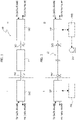
Figure 1 is a block diagram illustrative of aconventional communication system 10 comprising agalvanic isolation link 12 which may be used to provide communication between a "first" side I and a "second" side II. - Electrical, or galvanic, isolation is the condition in which:
- no appreciable direct current (DC) circulation takes place between two points of differing electrical potential: this condition corresponds to a notionally infinite electrical resistance between the two points, and
- electrical energy (a signal varying over time, for instance) can still be exchanged by other physical phenomena, such as electromagnetic induction, capacitive coupling, or light.
- In a possible application context, the first and second sides I and II of the
communication system 10 may be the (low-voltage) control side and the (high-voltage) power side of a traction system of a motor vehicle (not visible in the figures) where an electric motor is used as a source of traction power in the place of, or in combination with, a conventional internal combustion engine. - Of course, reference to that possible application context is merely illustrative and not limiting of the embodiments.
- A system as illustrated in
Figure 1 comprises, on both sides I and II, a transmitter/receiver (transceiver) circuit 101 (side I) and 102 (side II) configured to: - receive input data to be transmitted to the other side (TX DATA FRAME); and
- output data received from the other side (RX DATA FRAME) .
- Galvanic isolation (indicated by ISO in the figure), of the low-voltage side from the high-voltage side (together with possibility of exchanging data therebetween) is facilitated by a transformer or
capacitor 12 which, on the one hand, counters transfer of DC signal components between the sides I and II and, on the other hand, facilitates propagation therebetween of AC signal components such as pulsed data signals. - All of the foregoing is conventional in the art, which makes it unnecessary to provide a more detailed description herein.
- A conventional arrangement as illustrated in
Figure 1 can be regarded as essentially analog, with a digital part involved in providing a bitstream to be transmitted together with a clock signal. - An analog encoder block as included in both 101 and 102 builds the signal to be transmitted (for instance, a two-level pulsed signal corresponding to "1" and "0" symbols) starting from these two inputs. A likewise analog decoder block on the receiver side uses a dedicated oscillator (8MHz, for instance) to reconstruct the data signal.
- Such a solution does not facilitate testing. Also, power consumption may be high, with a corresponding high-power consumption and IC semiconductor area occupation.
- Additionally, a solution as illustrated in
Figure 1 involves an oscillator for each receiver interface (on both sides I and II). - One or more embodiments as illustrated in
Figure 2 (where parts or elements like parts or elements already discussed in connection withFigure 1 are indicated with like reference symbols, so that a corresponding description will not be repeated for brevity) may retain the same system layout ofFigure 1 and adopt a communication protocol for managing communications between: - a low-voltage controller MC such as, for instance, a microcontroller (MASTER, side I, by way of example), and
- an isolated high-voltage driver HVD (SLAVE, side II, once more by way of example) of a high-voltage ("user") device EM.
- An electric motor used as a source of traction power in a motor vehicle in the place of, or in combination with, a conventional internal combustion engine may be exemplary of such a high-voltage device EM.
- One or more silicon carbide field-effect transistors controlling current through the windings of such an electric motor EM may be exemplary of such isolated high-voltage driver HVD.
- It is noted that both the low-voltage controller MC and the high-voltage driver HVD (and the high-voltage device EM) are outlined in dashed lines insofar as they may represent distinct elements from the embodiments.
- Once again, galvanic isolation (ISO) of the low-voltage side I from the high-voltage side II (together with the possibility of exchanging data therebetween) can be provided at 12 (as exemplified by a capacitor).
- In one or more embodiments as illustrated in
Figure 2 , communication may involve a "master" request followed by a "slave" answer. - In one or more embodiments, such an interplay may occur on a periodic basis (that is, within a time window CS for a request and an answer of fixed duration).
- The duration of such a time window can be dimensioned as a function of the length (number of bits) of the transmitted messages plus the received messages, the oscillator frequency and precision and the delays of the analog driver of the (e.g., capacitive) link 12.
- In one or more embodiments, the transceiver in the master device (here 101) may start communication independently from as response provide by the transceiver in the slave device (here 102).
- In one or more embodiments, the slave device answer may start in response to an end of the master device request being detected.
- This possible way of operation facilitates the slave device (here, by way of example, 102) in tracking the master device (here, by way of example, 101) even if the two devices have asynchronous time bases.
- Also, if the microcontroller MC (which may be configured for Serial Peripheral Interface, SPI operation), issues a (new) request while another request is still on-going, the master device (here, 101, on the left) may be send a "busy" feedback to the microcontroller MC.
- A read from the slave device (here, 102, on the right) can be loaded into a MISO (Master Input Slave Output) register ready to be sent to the microcontroller MC at a next Serial Peripheral Interface (SPI) access.
- One or more embodiments may thus contemplate using a half-duplex protocol, which may be advantageous due to such communication involving only one wire.
- One or more embodiments may adopt a protocol providing Manchester encoding/decoding of communication data which facilitates clock recovery (possibly on a per-bit basis), with smart time sharing for transmitting and receiving windows.
- As further detailed in
Figure 3 (where, once again, parts or elements like parts or elements already discussed in connection with the previous figures are indicated with like reference symbols, so that a corresponding description will not be repeated for brevity) both themaster device 101 and the slave device 102 (here on the left hand side I and on the right hand side II, respectively) comprise transmitter andreceiver circuits 1011, 1012 (master device) and 1021, 1022 (slave device) configured - in a manner known per se to those of skill the art - to transmit and receive data signals through the galvanic isolation 112, ISO. - As illustrated, the transmitter and
receiver circuits master device 101 operate under the control of control circuitry 1013 (for instance, an integrated communication interface or ICI, including configuration and status registers) configured to co-operate with the (micro)controller MC. - As illustrated, the transmitter and
receiver circuits slave device 102 co-operate with control circuitry 1023 (for instance, an integrated communication interface or ICI, including configuration and status registers) configured to co-operate with the high voltage drive circuitry HVD. -
Figure 4 reproduces for immediate reference parts or elements already introduced and discussed in the foregoing highlighting the role of these parts and elements in implementing a protocol to manage communications between the low-voltage side I and the high-voltage side II via integrated communication interfaces such as 1013 and 1023 for the "master"device 101 and the "slave"device 102, respectively. - In operation as illustrated herein, the
interfaces multiplexer circuits transmitters receivers 1012, 1002 in order to facilitate single-wire half-duplex communication over the galvanicallyisolated channel 12. - That is:
- the transmitter 1011 (via multiplexer 1014) and the receiver 1022 (via multiplexer 1024) are coupled to the galvanically
isolated channel 12 for transmission from side I (here, master) to side II (here slave), and - the transmitter 1021 (via multiplexer 1024) and the receiver 1012 (via multiplexer 1014) are coupled to the galvanically
isolated channel 12 for transmission from side II (here, slave) to side I (here master). - Flowpaths (lines) for corresponding Master Input Slave Output (MISO) and Master Output Slave Input (MOSI) messages are also represented in
Figure 4 . - In one or more embodiments, a protocol as discussed herein can be rendered safe by a watchdog supervising communication activity in both directions.
- As discussed, Manchester encoding/decoding can be advantageously selected in order to facilitate sending data and clock on a single line and for sending long messages (messages with many bits).
- This approach also facilitates clock recovery at each bit which makes a system as illustrated tolerant to oscillator mismatch (even as high as 12%) between the master device and the slave device.
- Operation as discussed above is exemplified in the diagrams of
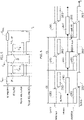
Figure 5 . - Those diagrams illustrate, plotted against a common (abscissa) time scale, possible time behaviors of (from top to bottom):
- messages (commands) ..., CN-1, CN, CN+1, ... from the master device to the slave device (here, from
device 101 to device 102), - messages (commands) ..., C'N-2, C'N-1, ... from the slave device to the master device (here, from
device 102 to device 101), - the signal TX/RX SEL SLAVE controlling the
multiplexer 1024 at theslave device 102, - the signal TX/RX SEL MASTER controlling the
multiplexer 1014 at themaster device 101. - It is noted that messages such as ..., C'N-2, C'N-1, ... in the second diagram are interleaved with the messages (commands) ..., CN-1, CN, CN+1, ... in the uppermost diagram with inter-frame safety guard intervals IF.
- Communication as exemplified herein involves master device requests each followed by a slave device answer.
- In +one or more embodiments, communication can be started periodically by the
master device 101 independently on any answer from theslave device 102. -
Figure 5 illustrates that the answer from theslave device 102 is started in response to the end of the request from themaster device 101 being detected. - As discussed, this facilitates having the
slave device 102 "tracking" themaster device 101 even if the two devices have asynchronous time bases. - In one or more embodiments, communication from the
master device 101 can be started by a starting event and follow a fixed time base that is dimensioned as a function of the (cumulative) length of the message transmitted plus the received message (a - purely exemplary - value can be 51.2 microseconds for sending and receiving 24-bit messages). - Bidirectional communication can be managed on each side (side I, side II) by the TX/RX SEL signal (namely TX/RX SEL SLAVE and TX/RX SEL MASTER), which is used:
- in the device which (at the time) is transmitting data, to enable the transmitter - 1011 or 1021 - and disable the associate receiver - 1012 or 1022).
- in the device which (at the time) is receiving data, to enable the receiver - 1012 or 1022 - and disable the associate transmitter - 1011 or 1021).
- Communication can start at the TX/RX SEL MASTER falling edge while is stopped at the TX/RX SEL SLAVE rising edge.
- As illustrated, the transmitting and receiving windows are dimensioned and timed (IF intervals) in such a way to avoid overlap of transmitting and receiving events. This may take into account the length of the message(s), that is the number of bits therein, the oscillator frequency (and accuracy) and the delays of the analog driver of the
capacitive line 12 providing the galvanic isolation. - The diagrams of
Figure 6 , which again share common (abscissa) time scales, are illustrative of embodiments where the master device (here 101, on the low-voltage side I) is configured to send to the slave device (here 102, on the high-voltage side II) two types ofmessages 2001, 2001'. - A first type of low-voltage to high-voltage (LV to HV) message (two upper diagrams in
Figure 6 ) is a LV toHV message 2001 where themaster device 101 polls the status of theslave device 102, which responds at 2002. - Such polling as exemplified at 2001 may involve a first type of access request, for instance a read request at a fixed register address in the
interface 1023. - Polling may be performed continuously (e.g., with a 24-bit constant code) at every communication slot CS (every 51.2 microseconds, for instance).
- As exemplified in the two lower diagrams in
Figure 6 , a second type of low-voltage to high-voltage (LV to HV) message may be prompted (by a SPI-HV message 2003) where themaster device 101 sends to the slave device 102 a second type of message 2001', for instance a write request at any register address in theinterface 1023 or a read request at any register address in the interface 1023 (other than the one possibly used to send the polling messages 2001). - The message 2001' may be prompted by an out-of-frame access request 2003 (SPI for instance) from the microcontroller MC and may result in action taken at the
slave side 102 as exemplified at 2002'. - As illustrated in
Figure 6 , the communication protocol and the communication windows (e.g., 24-bit constant code) for the messages 2001' (and the action at 2002') can be the same of thepolling messages - As noted, the (second type of) message 2001' may convey a write/read access to a register on the slave side 102 (ICI 1023).
- Considering by way of simplicity the exemplary case of a read request (originated from the controller MC), if the
access request 2003 from the microcontroller MC is received while another (e.g., polling) request is ongoing, the LV master device (here 101) may send a "busy" feedback (MISO=busy) to the microcontroller MC. - Under these circumstances, the read received from the HV device 102 (MISO=read HV) can be loaded into a MISO register and then sent to the microcontroller MC at the next SPI access (see 2002', 2003' in
Figure 6 , where 2003' denotes a SPI MISO=read HV message received by the microcontroller MC). - As discussed, one or more embodiments may use simple (constant) codes such as 24-bit constant codes, for instance, for communicating requests and status (see 2001 and 2002, for instance).
- For instance, the
master device 101 may send 24-bit constant code for polling for the status of theslave device 102 and theslave device 102 may answer with 24-bit constant codes indicating good status, fault status, communication error. - A same format (24 bit, for instance) can be used for the messages 2001' and 2002', and, advantageously, for the
requests 2003. - In both the
master device 101 and the slave device 102 a watchdog may be provided to reset the communication logic - putting it in an idle state - if no received message is detected for more that, e.g., four communication slots CS. - Such a reset can be made temporary, with communication restarted from the
master device 101 with a transmission event. - One or more embodiments facilitate letting a LV controller interface a 101 and a HV driver interface at 102 communicate with each other with an isolated protocol in a single IC, achieving communication speed, communication safety and reduced cost in terms of area.
- In comparison with essentially analog solutions, one or more embodiments provide advantages in terms of testability, area reduction, and robustness to noise.
- Digital encoding/decoding of communication data (Manchester for instance) provide a simple mechanism for managing a bidirectional communication line.
- Time division between transmit and receive windows, together with a slave device capable of tracking the master device facilitates synchronization and contribute in avoiding conflicts (collisions). Encoder and decoder logic includes a small number of gates, with registers on one side (HV registers) not duplicated on the other side (LV registers).
- Advantageously, no FIFO (First-In First-Out) queuing or additional blocks are involved on the LV side to record HV information: HV replies are loaded directly in a MISO.
- A smart time-sharing mechanism is adopted for transmission and reception time windows, capable of providing automatic and fast interrogation of HV (slave) status in addition to complying with requests from a microcontroller such as MC.
- The microcontroller MC can receive a reply to a request in two SPI frames (out-of-frame message OOF) during which the microcontroller MC obtains the reply. In that way, the microcontroller MC can be made aware of the driver state every 51.2 x 2 µs, for instance.
- In one or more embodiments, the LV side (here side I) may communicate with a microcontroller such as MC via SPI interface. A microcontroller such as MC can address configuration or diagnostic registers regarding both the LV side (side I) and the HV driver (side II).
- A request regarding the LV side can be dealt with within the LV side itself (thus facilitating completing LV requests in a short time). Conversely, if a request concerns the HV side, the LV side may take control of the communication line and wait for the HV reply.
- In one or more embodiments, a same communication pattern (TX/RX window) can be used for master-to-slave and microcontroller-to-master messages.
- Use of fixed codes in investigating and reporting the good/fault status of the slave device (HV actuator) part along with increased safety of the line facilitated by watchdog supervision along with automatic reset and restart of communication in case of line in stuck are other advantageous features of the embodiments.
- One or more embodiments facilitate communication between a low-voltage side and a high-voltage side within a single IC resorting to a simple, fully digital (and fully testable) arrangement, preserving adequate isolation, while having a reduced area occupation complying with safety specifications.
- Activity (that is, exchange of signals) over an isolated capacitive line as discussed herein and periodicity of the query and answer slots can be observed and measured during automatic polling and during microcontroller requests. In case of automatic polling the query and answer frames (constant 24-bit codes) can be recognized.
- In case of a fault on the HV side (side II), the answer frame can be a constant 24-bit code reporting the fault status.
- In case of a request from a microcontroller such as MC (side I) to the HV side (side II) the answer sent to can again be a constant 24-bit "busy" code which is repeated at each subsequent request until the answer is recovered from the HV isolated side (side II).
- A method (protocol) as exemplified herein may comprise:
- exchanging data signals (for instance, 2001, 2002, 2001', 2002') via a galvanic isolation link (for instance, ISO, 12) coupling a first unit (for instance, 101) and a second unit (for instance, 102), wherein exchanging data signals occurs in subsequent time slots (for instance, CS) of fixed time duration (and periodical occurrence, 51.2 µs, for instance) during which first data signals (for instance, 2001, 2001') are sent from the first unit and received by the second unit and second data signals (for instance, 2002, 2002') are sent from the second unit in response to first data signals received from the first unit,
- wherein:
- the first data signals comprise polling signals (for instance, 2001) sent from the first unit to the second unit at each one of said subsequent time slots as well as on-demand requests (for instance, 2001') sent from the first unit to the second unit in response to respective accesses (for instance, 2003, 2003') to said first unit (for instance, by the microcontroller MC), and
- the second data signals comprise status response signals (for instance, 2002) sent from the second unit in response to polling signals from the first unit as well as read signals (for instance, 2002') from the second unit sent from the second unit in response to on-demand requests (for instance, 2001') from the first unit.
- A method as exemplified herein may comprise:
- keeping in store a read signal (for instance, 2002') from the second unit pending completion of sending a status response signal (for instance, 2002) from the second unit to the first unit, and
- sending (for instance, MISO=read HV) said read signal kept in store in response to a respective (subsequent) access (for instance, 2003') to said first unit.
- For instance, as exemplified in
Figure 6 , the foregoing may involve the following procedure: - a request (read and write) 2003 from the microcontroller MC is kept in store as long as an on-going
message 2002 is completed, and - a corresponding response 2002' is stored and retrieved at a "next" access by the microcontroller MC.
- A method as exemplified herein may comprise the first unit issuing a busy state signal (for instance, MISO=busy) indicative of said pending completion of sending a status response signal from the second unit to the first unit.
- In a method as exemplified herein, the second unit may comprise registers (for instance, 1023), and:
- the polling signals sent from the first unit to the second unit may comprise a first type of access requests (for instance, read) to said registers in the second unit, and
- the on-demand requests sent from the first unit to the second unit may comprise a second type of access requests (for instance, write or read) to said registers in the second unit, the second type of access requests being different from the first type of access requests.
- In a method as exemplified herein:
- the registers in the second unit may have register addresses,
- the first type of access requests to said registers in the second unit may comprise access requests to a single one of said register addresses in the second unit, and
- the second type of access requests to said registers in the second unit may comprise access requests to a plurality of said register addresses in the second unit.
- In a method as exemplified herein:
- the first data signals (for instance, 2001, 2001') and the second data signals (for instance, 2002, 2002') may be mutually non-overlapping (see, for instance, IF or TX/RX SEL MASTER and TX/RX SEL SLAVE in
Figure 5 ); and/or - the first data signals and the second data signals may comprise a same number of bits (for instance, 24 bits); and/or
- the first data signals and the second data signals may comprise digitally-encoded signals, optionally using Manchester code; and/or
- the polling signals from the first unit to the second unit and the status response signals from the second unit to the first unit may comprise constant-content digital signals.
- A method as exemplified herein may comprise:
- watching absence of data signals (for instance, 2001, 2002, 2001', 2002') sent via said galvanic isolation link,
- in response to absence of data signals sent over said galvanic isolation link being detected by one of said first unit and said second unit for a threshold number of said subsequent time slots (for instance, four time slots CS), resetting said one of said first unit (101) and said second unit (102) and restarting operation with a first data signal (for instance, 2001, 2001') sent from the first unit and received by the second unit.
- A communication system (for instance, 10) as exemplified herein, may comprise a first unit and a second unit coupled via a galvanic isolation link, wherein the first unit and the second unit may be configured to exchange data signals with the method as exemplified herein.
- A system as exemplified herein may comprise a controller (for instance, MC) configured to:
- send to the first unit respective access requests (for instance, 2003), and
- receive from the first unit said read signals read from the second unit sent from the second unit to the first unit in response to said on-demand requests.
- In a system as exemplified herein:
- the first unit may comprise a low-voltage circuit configured to control a high-voltage device (for instance, EM), and
- the second unit may be configured to be coupled (for instance, via drive unit such as HVD) to said high-voltage device, wherein the galvanic isolation link provides isolation of said low-voltage control circuit with respect to said high-voltage device.
- A high-voltage device (for instance, an electric motor such as EM) may be equipped with a system as exemplified herein, wherein said second unit is coupled to said high-voltage device and said first unit is configured to control said high-voltage device with the galvanic isolation link providing isolation of said low-voltage control circuit with respect to said high-voltage device.
- Without prejudice to the underlying principles, the details and embodiments may vary, even significantly, with respect to what has been described by way of example only without departing from the extent of protection.
- The extent of protection is determined by the annexed claims.
Claims (11)
- A method, comprising:exchanging data signals (2001, 2002, 2001', 2002') via a galvanic isolation link (ISO, 12) coupling a first unit (101) and a second unit (102), wherein exchanging data signals occurs in subsequent time slots (CS) of fixed time duration during which first data signals (2001, 2001') are sent from the first unit (101) and received by the second unit (102) and second data signals (2002, 2002') are sent from the second unit (102) in response to first data signals (2001, 2001') received from the first unit (101),wherein:the first data signals comprise polling signals (2001) sent from the first unit (101) to the second unit (102) at each one of said subsequent time slots (CS) as well as on-demand requests (2001') sent from the first unit (101) to the second unit (102) in response to respective accesses (2003, 2003') to said first unit (101), andthe second data signals comprise status response signals (2002) sent from the second unit (102) in response to polling signals (2001) from the first unit (101) as well as read signals (2002') from the second unit (102) sent from the second unit (102) in response to on-demand requests (2001') from the first unit (101) .
- The method of claim 1, comprising:keeping in store a read signal (2002') pending completion of sending a status response signal (2002) from the second unit (102) to the first unit (101), andsending (MISO=read HV) said signal kept in store (2002') in response to a respective access (2003') to said first unit (101).
- The method of claim 2, comprising the first unit (101) issuing a busy state signal (MISO=busy) indicative of said pending completion of sending a status response signal (2002) from the second unit (102) to the first unit (101).
- The method of any of the previous claims, wherein the second unit (102) comprises registers (1023), and wherein:the polling signals (2001) sent from the first unit (101) to the second unit (102) comprise a first type of access requests to said registers (1023) in the second unit (102), andthe on-demand requests (2001') sent from the first unit (101) to the second unit (102) comprise a second type of access requests to said registers (1023) in the second unit (102), the second type of access requests being different from the first type of access requests.
- The method of claim 4, wherein:the registers (1023) in the second unit (102) have register addresses,the first type of access requests to said registers (1023) in the second unit (102) comprise access requests to a single one of said register addresses in the second unit (102), andthe second type of access requests to said registers (1023) in the second unit (102) comprise access requests to a plurality of said register addresses in the second unit (102).
- The method of any of the previous claims, wherein:the first data signals (2001, 2001') and the second data signals (2002, 2002') are mutually non-overlapping (IF; TX/RX SEL MASTER, TX/RX SEL SLAVE); and/orthe first data signals (2001, 2001') and the second data signals (2002, 2002') comprise a same number of bits; and/orthe first data signals (2001, 2001') and the second data signals (2002, 2002') comprise digitally-encoded signals, preferably using Manchester code; and/orthe polling signals (2001) from the first unit (101) to the second unit (102) and the status response signals (2002) from the second unit (102) to the first unit (101) comprise constant-content digital signals.
- The method of any of the previous claims, comprising:watching absence of data signals (2001, 2002, 2001', 2002') sent via said galvanic isolation link (ISO, 12),in response to absence of data signals (2001, 2002, 2001', 2002') sent over said galvanic isolation link (ISO, 12) being detected by one of said first unit (101) and said second unit (102) for a threshold number of said subsequent time slots (CS), resetting said one of said first unit (101) and said second unit (102) and restarting operation with a first data signal (2001, 2001') sent from the first unit (101) and received by the second unit (102).
- A system (10), comprising a first unit (101) and a second unit (102) coupled via a galvanic isolation link (ISO, 12), wherein the first unit (101) and the second unit (102) are configured to exchange data signals (2001, 2002, 2001', 2002') with the method of any of claims 1 to 7.
- The system (10) of claim 8, comprising a controller (MC) configured to:send to the first unit (101) respective access requests (2003), andreceive from the first unit (101) said read signals (2002') read from the second unit (102) sent from the second unit (102) to the first unit (101) in response to said on-demand requests (2001').
- The system (10) of claim 8 or claim 9, wherein:the first unit (101) comprises a low-voltage circuit configured to control a high-voltage device (EM), andthe second unit (102) is configured to be coupled (HVD) to said high-voltage device (EM), wherein the galvanic isolation link (ISO, 12) provides isolation of said low-voltage control circuit (101) with respect to said high-voltage device (EM).
- A high-voltage device (EM) equipped with a system according to any of claims 8 to 10, wherein said second unit (102) is coupled (HVD) to said high-voltage device (EM) and said first unit (101) is configured to control said high-voltage device (EM) with the galvanic isolation link (ISO, 12) providing isolation of said low-voltage control circuit (101) with respect to said high-voltage device (EM).
Applications Claiming Priority (1)
| Application Number | Priority Date | Filing Date | Title |
|---|---|---|---|
| IT202000022678 | 2020-09-25 |
Publications (2)
| Publication Number | Publication Date |
|---|---|
| EP3975493A1 true EP3975493A1 (en) | 2022-03-30 |
| EP3975493B1 EP3975493B1 (en) | 2025-10-29 |
Family
ID=73643284
Family Applications (1)
| Application Number | Title | Priority Date | Filing Date |
|---|---|---|---|
| EP21195778.2A Active EP3975493B1 (en) | 2020-09-25 | 2021-09-09 | Communication method, corresponding system and device |
Country Status (2)
| Country | Link |
|---|---|
| US (1) | US11575404B2 (en) |
| EP (1) | EP3975493B1 (en) |
Cited By (1)
| Publication number | Priority date | Publication date | Assignee | Title |
|---|---|---|---|---|
| CN118137681A (en) * | 2024-05-08 | 2024-06-04 | 广东立胜电力技术有限公司 | A real-time remote monitoring system and method for temporary disconnection points of overhead lines |
Families Citing this family (2)
| Publication number | Priority date | Publication date | Assignee | Title |
|---|---|---|---|---|
| US12538292B2 (en) * | 2021-09-24 | 2026-01-27 | Apple Inc. | Receive (RX) rate control for thread coexistence with other radios |
| US12005911B2 (en) * | 2022-07-25 | 2024-06-11 | Fca Us Llc | Robust techniques for managing primary and secondary controllers on CAN-FD networks |
Citations (3)
| Publication number | Priority date | Publication date | Assignee | Title |
|---|---|---|---|---|
| EP0755137A1 (en) * | 1995-07-20 | 1997-01-22 | Raytheon Company | Deterministic network protocol |
| US20110289248A1 (en) * | 2010-05-21 | 2011-11-24 | National Semiconductor Corporation | Isolated communication bus and related protocol |
| EP3547620A1 (en) * | 2018-03-26 | 2019-10-02 | STMicroelectronics Application GmbH | A communication method, corresponding system, devices, signal and vehicle |
Family Cites Families (6)
| Publication number | Priority date | Publication date | Assignee | Title |
|---|---|---|---|---|
| US6359973B1 (en) * | 1998-11-16 | 2002-03-19 | Conexant Systems, Inc. | Data access arrangement utilizing a serialized digital data path across an isolation barrier |
| JP3839267B2 (en) * | 2001-03-08 | 2006-11-01 | 株式会社ルネサステクノロジ | Semiconductor device and communication terminal device using the same |
| US7737871B2 (en) * | 2004-06-03 | 2010-06-15 | Silicon Laboratories Inc. | MCU with integrated voltage isolator to provide a galvanic isolation between input and output |
| US9155127B1 (en) * | 2011-12-15 | 2015-10-06 | Marvell International Ltd. | Method and apparatus for coexistence transceiver system |
| US9680528B2 (en) * | 2014-10-28 | 2017-06-13 | Nxp B.V. | Communication between capacitive-isolated devices |
| US10129059B2 (en) * | 2016-06-03 | 2018-11-13 | Texas Instruments Incorporated | Low latency multi-amplitude modulation receiver |
-
2021
- 2021-09-09 EP EP21195778.2A patent/EP3975493B1/en active Active
- 2021-09-21 US US17/480,926 patent/US11575404B2/en active Active
Patent Citations (3)
| Publication number | Priority date | Publication date | Assignee | Title |
|---|---|---|---|---|
| EP0755137A1 (en) * | 1995-07-20 | 1997-01-22 | Raytheon Company | Deterministic network protocol |
| US20110289248A1 (en) * | 2010-05-21 | 2011-11-24 | National Semiconductor Corporation | Isolated communication bus and related protocol |
| EP3547620A1 (en) * | 2018-03-26 | 2019-10-02 | STMicroelectronics Application GmbH | A communication method, corresponding system, devices, signal and vehicle |
Cited By (1)
| Publication number | Priority date | Publication date | Assignee | Title |
|---|---|---|---|---|
| CN118137681A (en) * | 2024-05-08 | 2024-06-04 | 广东立胜电力技术有限公司 | A real-time remote monitoring system and method for temporary disconnection points of overhead lines |
Also Published As
| Publication number | Publication date |
|---|---|
| US20220103201A1 (en) | 2022-03-31 |
| EP3975493B1 (en) | 2025-10-29 |
| US11575404B2 (en) | 2023-02-07 |
Similar Documents
| Publication | Publication Date | Title |
|---|---|---|
| EP3975493B1 (en) | Communication method, corresponding system and device | |
| US9559389B2 (en) | Daisy chain communication bus and protocol | |
| US7028105B2 (en) | Apparatus, method and signal set for monoline serial interface | |
| US5479395A (en) | Serial bus system | |
| CA1191918A (en) | Multipoint data communication system with local arbitration | |
| US11171807B2 (en) | Method and apparatus for allocating priority transmission opportunities in vehicle network | |
| CN102067508B (en) | A high speed data transmission method and corresponding devices | |
| JPH04117743A (en) | Optical transceiver | |
| EP2458772A2 (en) | Method and system for synchronizing a network using existing network cables | |
| CN111030909A (en) | Method for time synchronization among CAN bus multi-master device communication | |
| EP0081821B1 (en) | System of local area contention networks | |
| WO2022021869A1 (en) | Single-level single-line full-duplex bus communication method and system | |
| RU2586580C2 (en) | Conflict detection in eia-485 buses | |
| EP3327579A1 (en) | Serial data communications using a uart module and method therefor | |
| CN111555946A (en) | Subscriber station of a bus system and method for transmitting data in a bus system | |
| CN114257262B (en) | Communication method, corresponding system and equipment | |
| CN111949583B (en) | Single-wire bidirectional communication system and communication method | |
| US7406555B2 (en) | Systems and methods for multiple input instrumentation buses | |
| CN113722254B (en) | Multi-host communication bus system suitable for industrial control site | |
| CN118302995A (en) | Vehicle-mounted communication device and operation method thereof | |
| CN108241590B (en) | Serial data bus applied to underwater vehicle | |
| CN110576884B (en) | Vehicle RS485 cascade communication method for rail transit | |
| CN112100112B (en) | Full duplex bus and train | |
| CN121644006A (en) | Response messages in asynchronous communications | |
| SU1345205A1 (en) | Information exchange device |
Legal Events
| Date | Code | Title | Description |
|---|---|---|---|
| PUAI | Public reference made under article 153(3) epc to a published international application that has entered the european phase |
Free format text: ORIGINAL CODE: 0009012 |
|
| STAA | Information on the status of an ep patent application or granted ep patent |
Free format text: STATUS: THE APPLICATION HAS BEEN PUBLISHED |
|
| AK | Designated contracting states |
Kind code of ref document: A1 Designated state(s): AL AT BE BG CH CY CZ DE DK EE ES FI FR GB GR HR HU IE IS IT LI LT LU LV MC MK MT NL NO PL PT RO RS SE SI SK SM TR |
|
| STAA | Information on the status of an ep patent application or granted ep patent |
Free format text: STATUS: REQUEST FOR EXAMINATION WAS MADE |
|
| 17P | Request for examination filed |
Effective date: 20220725 |
|
| RBV | Designated contracting states (corrected) |
Designated state(s): AL AT BE BG CH CY CZ DE DK EE ES FI FR GB GR HR HU IE IS IT LI LT LU LV MC MK MT NL NO PL PT RO RS SE SI SK SM TR |
|
| STAA | Information on the status of an ep patent application or granted ep patent |
Free format text: STATUS: EXAMINATION IS IN PROGRESS |
|
| 17Q | First examination report despatched |
Effective date: 20230524 |
|
| GRAP | Despatch of communication of intention to grant a patent |
Free format text: ORIGINAL CODE: EPIDOSNIGR1 |
|
| STAA | Information on the status of an ep patent application or granted ep patent |
Free format text: STATUS: GRANT OF PATENT IS INTENDED |
|
| INTG | Intention to grant announced |
Effective date: 20250508 |
|
| GRAS | Grant fee paid |
Free format text: ORIGINAL CODE: EPIDOSNIGR3 |
|
| GRAA | (expected) grant |
Free format text: ORIGINAL CODE: 0009210 |
|
| STAA | Information on the status of an ep patent application or granted ep patent |
Free format text: STATUS: THE PATENT HAS BEEN GRANTED |
|
| AK | Designated contracting states |
Kind code of ref document: B1 Designated state(s): AL AT BE BG CH CY CZ DE DK EE ES FI FR GB GR HR HU IE IS IT LI LT LU LV MC MK MT NL NO PL PT RO RS SE SI SK SM TR |
|
| REG | Reference to a national code |
Ref country code: CH Ref legal event code: F10 Free format text: ST27 STATUS EVENT CODE: U-0-0-F10-F00 (AS PROVIDED BY THE NATIONAL OFFICE) Effective date: 20251029 Ref country code: GB Ref legal event code: FG4D |
|
| REG | Reference to a national code |
Ref country code: IE Ref legal event code: FG4D |
|
| REG | Reference to a national code |
Ref country code: DE Ref legal event code: R096 Ref document number: 602021041156 Country of ref document: DE |
|
| REG | Reference to a national code |
Ref country code: NL Ref legal event code: MP Effective date: 20251029 |
|
| PG25 | Lapsed in a contracting state [announced via postgrant information from national office to epo] |
Ref country code: ES Free format text: LAPSE BECAUSE OF FAILURE TO SUBMIT A TRANSLATION OF THE DESCRIPTION OR TO PAY THE FEE WITHIN THE PRESCRIBED TIME-LIMIT Effective date: 20251029 |
|
| REG | Reference to a national code |
Ref country code: LT Ref legal event code: MG9D |
|
| PG25 | Lapsed in a contracting state [announced via postgrant information from national office to epo] |
Ref country code: NO Free format text: LAPSE BECAUSE OF FAILURE TO SUBMIT A TRANSLATION OF THE DESCRIPTION OR TO PAY THE FEE WITHIN THE PRESCRIBED TIME-LIMIT Effective date: 20260129 |
|
| PG25 | Lapsed in a contracting state [announced via postgrant information from national office to epo] |
Ref country code: HR Free format text: LAPSE BECAUSE OF FAILURE TO SUBMIT A TRANSLATION OF THE DESCRIPTION OR TO PAY THE FEE WITHIN THE PRESCRIBED TIME-LIMIT Effective date: 20251029 Ref country code: AT Free format text: LAPSE BECAUSE OF FAILURE TO SUBMIT A TRANSLATION OF THE DESCRIPTION OR TO PAY THE FEE WITHIN THE PRESCRIBED TIME-LIMIT Effective date: 20251029 Ref country code: FI Free format text: LAPSE BECAUSE OF FAILURE TO SUBMIT A TRANSLATION OF THE DESCRIPTION OR TO PAY THE FEE WITHIN THE PRESCRIBED TIME-LIMIT Effective date: 20251029 |
|
| REG | Reference to a national code |
Ref country code: AT Ref legal event code: MK05 Ref document number: 1852945 Country of ref document: AT Kind code of ref document: T Effective date: 20251029 |
|
| PG25 | Lapsed in a contracting state [announced via postgrant information from national office to epo] |
Ref country code: NL Free format text: LAPSE BECAUSE OF FAILURE TO SUBMIT A TRANSLATION OF THE DESCRIPTION OR TO PAY THE FEE WITHIN THE PRESCRIBED TIME-LIMIT Effective date: 20251029 |
|
| PG25 | Lapsed in a contracting state [announced via postgrant information from national office to epo] |
Ref country code: RS Free format text: LAPSE BECAUSE OF FAILURE TO SUBMIT A TRANSLATION OF THE DESCRIPTION OR TO PAY THE FEE WITHIN THE PRESCRIBED TIME-LIMIT Effective date: 20260129 |
|
| PG25 | Lapsed in a contracting state [announced via postgrant information from national office to epo] |
Ref country code: IS Free format text: LAPSE BECAUSE OF FAILURE TO SUBMIT A TRANSLATION OF THE DESCRIPTION OR TO PAY THE FEE WITHIN THE PRESCRIBED TIME-LIMIT Effective date: 20260228 |
|
| PG25 | Lapsed in a contracting state [announced via postgrant information from national office to epo] |
Ref country code: PT Free format text: LAPSE BECAUSE OF FAILURE TO SUBMIT A TRANSLATION OF THE DESCRIPTION OR TO PAY THE FEE WITHIN THE PRESCRIBED TIME-LIMIT Effective date: 20260302 |
|
| PG25 | Lapsed in a contracting state [announced via postgrant information from national office to epo] |
Ref country code: PL Free format text: LAPSE BECAUSE OF FAILURE TO SUBMIT A TRANSLATION OF THE DESCRIPTION OR TO PAY THE FEE WITHIN THE PRESCRIBED TIME-LIMIT Effective date: 20251029 |
|
| PG25 | Lapsed in a contracting state [announced via postgrant information from national office to epo] |
Ref country code: LV Free format text: LAPSE BECAUSE OF FAILURE TO SUBMIT A TRANSLATION OF THE DESCRIPTION OR TO PAY THE FEE WITHIN THE PRESCRIBED TIME-LIMIT Effective date: 20251029 |
|
| PG25 | Lapsed in a contracting state [announced via postgrant information from national office to epo] |
Ref country code: BG Free format text: LAPSE BECAUSE OF FAILURE TO SUBMIT A TRANSLATION OF THE DESCRIPTION OR TO PAY THE FEE WITHIN THE PRESCRIBED TIME-LIMIT Effective date: 20251029 |