EP3975490B1 - Verfahren zur wegbestimmung und zugehörige vorrichtung - Google Patents
Verfahren zur wegbestimmung und zugehörige vorrichtung Download PDFInfo
- Publication number
- EP3975490B1 EP3975490B1 EP20840937.5A EP20840937A EP3975490B1 EP 3975490 B1 EP3975490 B1 EP 3975490B1 EP 20840937 A EP20840937 A EP 20840937A EP 3975490 B1 EP3975490 B1 EP 3975490B1
- Authority
- EP
- European Patent Office
- Prior art keywords
- node
- type
- nodes
- paths
- transmission
- Prior art date
- Legal status (The legal status is an assumption and is not a legal conclusion. Google has not performed a legal analysis and makes no representation as to the accuracy of the status listed.)
- Active
Links
Images
Classifications
-
- H—ELECTRICITY
- H04—ELECTRIC COMMUNICATION TECHNIQUE
- H04L—TRANSMISSION OF DIGITAL INFORMATION, e.g. TELEGRAPHIC COMMUNICATION
- H04L41/00—Arrangements for maintenance, administration or management of data switching networks, e.g. of packet switching networks
- H04L41/12—Discovery or management of network topologies
-
- H—ELECTRICITY
- H04—ELECTRIC COMMUNICATION TECHNIQUE
- H04L—TRANSMISSION OF DIGITAL INFORMATION, e.g. TELEGRAPHIC COMMUNICATION
- H04L43/00—Arrangements for monitoring or testing data switching networks
- H04L43/08—Monitoring or testing based on specific metrics, e.g. QoS, energy consumption or environmental parameters
- H04L43/0852—Delays
-
- H—ELECTRICITY
- H04—ELECTRIC COMMUNICATION TECHNIQUE
- H04L—TRANSMISSION OF DIGITAL INFORMATION, e.g. TELEGRAPHIC COMMUNICATION
- H04L43/00—Arrangements for monitoring or testing data switching networks
- H04L43/10—Active monitoring, e.g. heartbeat, ping or trace-route
-
- H—ELECTRICITY
- H04—ELECTRIC COMMUNICATION TECHNIQUE
- H04L—TRANSMISSION OF DIGITAL INFORMATION, e.g. TELEGRAPHIC COMMUNICATION
- H04L45/00—Routing or path finding of packets in data switching networks
- H04L45/02—Topology update or discovery
-
- H—ELECTRICITY
- H04—ELECTRIC COMMUNICATION TECHNIQUE
- H04L—TRANSMISSION OF DIGITAL INFORMATION, e.g. TELEGRAPHIC COMMUNICATION
- H04L45/00—Routing or path finding of packets in data switching networks
- H04L45/12—Shortest path evaluation
- H04L45/121—Shortest path evaluation by minimising delays
-
- H—ELECTRICITY
- H04—ELECTRIC COMMUNICATION TECHNIQUE
- H04L—TRANSMISSION OF DIGITAL INFORMATION, e.g. TELEGRAPHIC COMMUNICATION
- H04L45/00—Routing or path finding of packets in data switching networks
- H04L45/12—Shortest path evaluation
- H04L45/124—Shortest path evaluation using a combination of metrics
-
- H—ELECTRICITY
- H04—ELECTRIC COMMUNICATION TECHNIQUE
- H04L—TRANSMISSION OF DIGITAL INFORMATION, e.g. TELEGRAPHIC COMMUNICATION
- H04L45/00—Routing or path finding of packets in data switching networks
- H04L45/34—Source routing
-
- H—ELECTRICITY
- H04—ELECTRIC COMMUNICATION TECHNIQUE
- H04L—TRANSMISSION OF DIGITAL INFORMATION, e.g. TELEGRAPHIC COMMUNICATION
- H04L45/00—Routing or path finding of packets in data switching networks
- H04L45/64—Routing or path finding of packets in data switching networks using an overlay routing layer
-
- H—ELECTRICITY
- H04—ELECTRIC COMMUNICATION TECHNIQUE
- H04L—TRANSMISSION OF DIGITAL INFORMATION, e.g. TELEGRAPHIC COMMUNICATION
- H04L41/00—Arrangements for maintenance, administration or management of data switching networks, e.g. of packet switching networks
- H04L41/50—Network service management, e.g. ensuring proper service fulfilment according to agreements
- H04L41/5003—Managing SLA; Interaction between SLA and QoS
- H04L41/5019—Ensuring fulfilment of SLA
Definitions
- This application relates to the field of communications technologies, and more specifically, to a path determining method and a related device.
- segment routing Segment Routing, SR
- 5G 5 th Generation
- the SR technologies may be classified into two types: an SR technology based on multi-protocol label switching (Multi-Protocol Label Switching, MPLS), which may be referred to as SR-MPLS, and an SR technology based on the internet protocol version 6 (Internet Protocol Version, IPv6), which may be referred to as SRv6.
- MPLS Multi-Protocol Label Switching
- IPv6 Internet Protocol Version
- US 2014/036726 A1 discloses a network that includes a data forwarding node including: a logical network topology management unit managing a correspondence relationship among at least two different logical network topologies generated by applying different policies to a physical network topology and data traffic conditions to which the logical network topologies are applied; and a packet processing unit selecting a logical network topology corresponding to data traffic to which an incoming packet belongs, determining a packet forwarding destination, and transmitting the incoming packet.
- the data forwarding node selects a logical network and forwards a packet, based on data traffic.
- WO 2017/141079 A1 discloses that a router operates in both a Segment Routing (SR) network portion and a Multiprotocol Label Switching (MPLS) network portion of a network that utilizes Intermediate System to Intermediate System (IS-IS).
- the router receives an IS-IS advertisement message originated by a mapping server that includes a sub-Type-length-value (sub-TLV) element that identifies a preferred type of path across the MPLS network portion for an identifiable set of traffic to be received by the router from the SR network portion.
- sub-TLV sub-Type-length-value
- the router identifies, based at least in part upon the sub-TLV element, one path of a plurality of available paths across the MPLS network portion for the identifiable set of traffic, and configures its forwarding plane to utilize the identified one path for the identifiable set of traffic.
- the IS-IS advertisement message can be an IS-IS TLV such as a SID/Label Binding TLVor Multi-topology SID/Label Binding TLV.
- CN 109922004 A discloses a traffic engineering method of an IPv6 network based on partially deployed segmented routing.
- the traffic engineering method comprises the following steps: acquiring a network topology of the IPv6 network, an initial network link weight matrix and a plurality of traffic matrixes within a set time length; based on the plurality of flow matrixes in the set time length, calculating a representative flow matrix in the set time length; based on the network topology, the initial network link weight matrix and the representative flow matrix, carrying out M times of training on the deep reinforcement learning network, and according to the Mth time of training of the deep reinforcement learning network, determining an optimized network link weight matrix, a segmented routing node set and a corresponding minimized maximum link utilization rate; wherein M is a positive integer greater than 0.
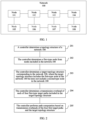
- This application provides a path determining method and a related device, so that a new network topology may be established by using an existing network topology structure, to reduce difficulty in path computation, thereby reducing a burden of a management device.
- the invention is set out in the appended set of claims.
- an embodiment of this application provides a path determining method, including: determining N 1 first-type nodes from N nodes included in a first network topology, where the N nodes include the N 1 first-type nodes and N 2 second-type nodes, the first-type node supports segment routing over internet protocol version 6 SRv6, N 1 is a positive integer greater than or equal to 2, and N 2 is a positive integer greater than or equal to 1; determining a second network topology corresponding to the first network topology, where the second network topology includes the N 1 first-type nodes but does not include the N 2 second-type nodes, the target topology structure includes M first-type target paths, an i th first-type target path in the M first-type target paths corresponds to K i paths in the first network topology, a source node and a destination node of the K i paths are the same as a source node and a destination node of the i th first-type target path, each of the K i paths includes
- a new network topology may be established by using an existing network topology structure.
- the new network topology includes only some nodes in the original network topology, and all these nodes support SRv6. In this way, difficulty in path computation may be reduced, to reduce a burden of a management device.
- the first-type node is a node that supports SRv6 in the N nodes
- the second-type node is a node that does not support SRv6 in the N nodes.
- the first-type node is a key node in the N nodes
- the second-type node is a non-key node in the N nodes.
- a node that does not support SRv6 and/or a non-key node in the original network topology may be removed, to obtain the new network topology. All nodes in the network topology support SRv6. In this way, even if a node that does not support SRv6 exists in a network, a packet may be forwarded based on a path determined by the management device. Alternatively, the non-key node is ignored during path computation, so that the difficulty in path computation may be reduced, to reduce the burden of the management device.
- the method further includes: obtaining a transmission overhead between two adjacent nodes in the first network topology.
- the determining transmission overheads of the M first-type target paths includes: determining a transmission overhead of each of the K i paths based on a transmission overhead between two adjacent nodes on each of the K i paths, and determining the smallest value of the transmission overheads of the K i paths as the transmission overhead of the i th first-type target path.
- the determining transmission overheads of the M first-type target paths includes: performing transmission overhead measurement on the i th first-type target path to obtain the transmission overhead of the i th first-type target path.
- the transmission overhead of the i th first-type target path may be directly obtained through measurement by using the foregoing technical solution.
- a transmission overhead when a transmission overhead is obtained through measurement, a node on a path forwards a measurement packet based on a shortest path. Therefore, the obtained transmission overhead is a smallest transmission overhead. Therefore, the smallest value of the transmission overheads may be directly obtained by using the foregoing technical solution, to reduce a workload of the management device.
- the performing transmission overhead measurement on the i th first-type target path to obtain the transmission overhead of the i th first-type target path includes: sending measurement information to the source node and/or the destination node of the i th first-type target path; and receiving measurement feedback information from the source node and/or the destination node of the i th first-type target path, where the measurement feedback information includes the transmission overhead of the i th first-type target path.
- the second network topology further includes P second-type target paths, and each of the P second-type target paths includes two of the N 1 first-type nodes, and the first network topology includes the P second-type target paths.
- the transmission overhead includes a transmission cost and/or a transmission delay.
- an embodiment of this application provides a management device.
- the management device includes units configured to implement any possible implementation of the method design in the first aspect.
- the management device may be a computer device or a component (for example, a chip or a circuit) configured for a computer device.
- an embodiment of this application provides a computer-readable medium.
- the computer-readable medium stores program code.
- the computer program code is run on a computer, the computer is enabled to perform the method in any possible implementation of the method design in the first aspect.
- example and “such as” are used to represent giving an example, an illustration, or a description. Any embodiment or design scheme described as an “example” in this application should not be explained as being more preferred or having more advantages than another embodiment or design scheme. Exactly, the term “example” is used to present a concept in a specific manner.
- FIG. 1 is a schematic diagram of a network structure.
- a network 100 shown in FIG. 1 includes eight nodes: a node 101, a node 102, a node 103, a node 104, a node 105, a node 106, a node 107, and a node 108.
- the network 100 may be a complete network or part of a complete network.
- the nodes (namely, the node 101 to the node 108) in the network 100 shown in FIG. 1 may also be referred to as network nodes.
- the node may be a device such as a workstation, a server, a terminal device, or a network device. Each device may have a different IPv6 address.
- Two adjacent nodes (for example, the node 101 and the node 102, the node 102 and the node 103, or the node 101 and the node 105) in the network 100 shown in FIG. 1 may be connected by using a wired or wireless medium.
- both the first-type node and the second-type node support SRv6.
- the first-type node is a key node in the network 100
- the second-type node is a non-key node in the network 100.
- the key node may be a border node between two networks.
- the network may include an access layer, an aggregation layer, a core layer, and the like. Key nodes may be border nodes at these layers.
- the key node may be an egress edge node in a network.
- the non-key node may be another node other than the key node.
- the first-type node may be a node that supports SRv6 and the first-type node is a key node in the network 100
- the second-type node may be a node that does not support SRv6, or the second-type node may be a node that supports SRv6 and the second-type node is a non-key node in the network 100.
- the technical solutions of this application are described in detail in FIG. 2 .
- the node 102 and the node 106 are nodes that do not support SRv6.
- the node 101, the node 103, the node 104, the node 105, the node 107, and the node 108 are nodes that support SRv6. It may be understood that the specific embodiment shown in FIG. 2 is merely intended to help a person skilled in the art better understand the technical solutions of this application, but is not intended to limit the technical solutions of this application to a limited embodiment.
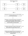
- FIG. 2 is a schematic flowchart of a path determining method according to an embodiment of this application.
- the method shown in FIG. 2 may be performed by a management device in a network.
- the management device may be a general-purpose computer device, for example, a notebook computer or a personal computer, or may be a dedicated network management device.
- the management device determines a topology structure of the network 100.
- the management device may establish a border gateway protocol-link state (Border Gateway Protocol-Link State, BGP-LS) or an interior gateway protocol (Interior Gateway Protocol, IGP) neighbor with the node in the network 100.
- BGP-LS Border Gateway Protocol-Link State
- IGP Interior Gateway Protocol
- the management device determines the first-type node from the nodes included in the network 100.
- the nodes in the network 100 may be classified into the first-type node and the second-type node based on whether the node supports SRv6.
- the first-type node is the node that supports SRv6, and the second-type node is the node that does not support SRv6.
- the network 100 includes six first-type nodes (namely, the node 101, the node 103, the node 104, the node 105, the node 107, and the node 108) and two second-type nodes (namely, the node 102 and the node 106) in total.
- the management device may obtain the SRv6 indication information in a process of determining the topology structure of the network 100.
- the management device may obtain topology information reported by each node in the network 100.
- the topology information includes the SRv6 indication information.
- the management device may send SRv6 query information to each node in the network 100.
- the node in the network 100 After receiving the SRv6 query information, the node in the network 100 sends SRv6 query feedback information to the management device.
- the SRv6 query feedback information is used to indicate whether the node supports SRv6.
- a path between the node 101 and the node 103, a path between the node 101 and the node 107, a path between the node 105 and the node 103, and a path between the node 105 and the node 107 are first-type target paths.
- the following describes the first-type target path by using the node 101 and the node 103 as an example.
- the first-type target path between the node 101 and the node 103 in the target topology structure 300 is referred to as a first-type target path 1.
- a path between two adjacent nodes in the network 100 is referred to as a link.
- a path between the node 101 and the node 102 is referred to as a link 12, a path between the node 102 and the node 103 is referred to as a link 23, and so on.
- a path 1 may include the link 12 and the link 23.
- a path 2 may include the link 12, a link 26, a link 67, and a link 73.
- a path 3 may include a link 15, a link 56, a link 62, and the link 23.
- a path 4 may include the link 15, the link 56, the link 67, and the link 73. It can be learned that each of the path 1 to the path 4 includes at least one second-type node.
- the path 1, the path 2, the path 3, and the path 4 may be referred to as paths corresponding to the first-type target path 1.
- the first-type target path 1 has four corresponding paths in the network 100: the path 1, the path 2, the path 3, and the path 4.
- the first-type target path between the node 101 and the node 107 also has a plurality of corresponding paths in the network 100.
- the first-type target path between the node 105 and the node 107 also has a plurality of corresponding paths in the network 100.
- the first-type target path between the node 105 and the node 103 also has a plurality of corresponding paths in the network 100.
- the management device may determine that the target topology structure includes four first-type target paths and five second-type target paths in total.
- the management device may determine a transmission overhead of each of the four first-type target paths.
- Con represents the transmission overhead
- C represents the transmission cost
- D represents the transmission delay
- ⁇ represents a weight coefficient corresponding to the transmission overhead
- ⁇ represents a weight coefficient corresponding to the transmission delay.
- ⁇ and ⁇ are numbers greater than 0.
- the first-type target path 1 is still used as an example to describe a specific implementation in which the management device determines the transmission overhead of the first-type target path.
- the management device may obtain a transmission overhead between two adjacent nodes on each of the four paths (namely, the path 1 to the path 4) corresponding to the first-type target path 1.
- topology information obtained by the management device may include a transmission overhead between two adjacent nodes in the network 100.
- the path 1 is used as an example.
- the management device may obtain a transmission overhead between the node 101 and the node 102 (namely, a transmission overhead of the link 12).
- the management device may further obtain a transmission overhead between the node 102 and the node 103 (namely, a transmission overhead of the link 23).
- the transmission overhead includes the transmission cost and the transmission delay.
- a smallest value of a plurality of transmission overheads may be a value of a transmission overhead with a smallest transmission delay in the plurality of transmission overheads.
- the transmission overhead includes the transmission cost and the transmission delay.
- a smallest value of a plurality of transmission overheads is a smallest value of the transmission delays.
- a smallest value of a plurality of transmission overheads is a smallest value of transmission costs.
- the target node may determine a transmission cost based on a transmission delay, and send the transmission cost to the management device as a transmission overhead.
- the management device may perform path computation based on the transmission overheads of the four first-type target paths and the target topology structure.
- the management device may determine, based on the four first-type target paths, whether the path reaches the node 108 through the node 103 or the node 107.
- the transmission overhead is the transmission delay.
- a transmission delay from the node 101 to the node 103 is 2 ms
- a transmission overhead from the node 101 to the node 107 is 3 ms
- a transmission overhead from the node 103 to the node 104 is 2 ms
- a transmission overhead from the node 104 to the node 108 is 1 ms
- a transmission overhead from the node 107 to the node 108 is 8 ms.
- FIG. 4 is a schematic flowchart of a path determining method according to an embodiment of this application.
- the method shown in FIG. 4 may be implemented by a management device or a component (for example, a chip or a circuit) in a management device.
- the first-type node is a node that supports SRv6 in the N nodes
- the second-type node is a node that does not support SRv6 in the N nodes.
- the first-type node is a key node in the N nodes
- the second-type node is a non-key node in the N nodes.
- determining the transmission overheads of the M first-type target paths includes: performing transmission overhead measurement on the i th first-type target path to obtain the transmission overhead of the i th first-type target path.
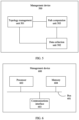
- the path computation unit 503 is configured to perform path computation based on the transmission overheads of the M first-type target paths and the second network topology.
- the first-type node is a node that supports SRv6 in the N nodes
- the second-type node is a node that does not support SRv6 in the N nodes.
- the first-type node is a key node in the N nodes
- the second-type node is a non-key node in the N nodes.
- a transmission overhead between two adjacent nodes in the first network topology is obtained.
- the data collection unit 502 is specifically configured to: determine a transmission overhead of each of the K i paths based on a transmission overhead between two adjacent nodes on each of the K i paths, and determine the smallest value of the transmission overheads of the K i paths as the transmission overhead of the i th first-type target path.
- the data collection unit 502 is specifically configured to perform transmission overhead measurement on the i th first-type target path to obtain the transmission overhead of the i th first-type target path
- the data collection unit 502 is specifically configured to: send measurement information to the source node and/or the destination node of the i th first-type target path; and receive measurement feedback information from the source node and/or the destination node of the i th first-type target path, where the measurement feedback information includes the transmission overhead of the i th first-type target path.
- the second network topology further includes P second-type target paths, each of the P second-type target paths includes two of the N 1 first-type nodes, and the first network topology includes the P second-type target paths.
- the transmission overhead includes a transmission cost and a transmission delay.
- the topology management unit 501, the data collection unit 502, and the path computation unit 503 may be implemented by a processor.
- FIG. 6 is a schematic structural block diagram of a management device according to an embodiment of this application.
- the management device 600 includes a bus 601, a processor 602, a communications interface 603, and a memory 604.
- the processor 602, the memory 604, and the communications interface 603 communicate with each other through the bus 601.
- the processor 602 may be a field programmable gate array (field programmable gate array, FPGA), an application-specific integrated circuit (application-specific integrated circuit, ASIC), system on chip (system on chip, SoC), a central processing unit (central processing unit, CPU), a network processor (network processor, NP), a digital signal processor (digital signal processor, DSP), a micro controller unit (micro controller unit, MCU), a programmable logic device (programmable logic device, PLD), another programmable logic device, a discrete gate or transistor logic device, a discrete hardware component, or another integrated chip.
- the memory 604 stores executable code included in a management device.
- the processor 602 reads the executable code in the memory 604 to perform the method shown in FIG. 2 or FIG. 4 .
- the memory 604 may further include another software module, such as an operating system, required for running a process.
- the operating system may be LINUX TM , UNIX TM , WINDOWS TM , or the
- steps in the foregoing methods can be implemented by using a hardware integrated logical circuit in the processor, or by using instructions in a form of software.
- the steps of the methods disclosed with reference to the embodiments of this application may be directly performed by a hardware processor, or may be performed by using a combination of hardware in the processor and a software module.
- the software module may be located in a mature storage medium in the art, such as a random access memory, a flash memory, a read-only memory, a programmable read-only memory, an electrically erasable programmable memory, or a register.
- the storage medium is located in the memory, and the processor reads information in the memory and completes the steps in the foregoing methods in combination with hardware of the processor. To avoid repetition, details are not described herein again.
- the processor in the embodiments of this application may be an integrated circuit chip, and has a signal processing capability.
- steps in the foregoing method embodiments can be implemented by using a hardware integrated logical circuit in the processor, or by using instructions in a form of software.
- a general-purpose processor may be a microprocessor, or the processor may be any conventional processor or the like.
- the steps of the methods disclosed with reference to the embodiments of this application may be directly performed and completed by a hardware decoding processor, or may be performed and completed by using a combination of hardware and software modules in the decoding processor.
- the software module may be located in a mature storage medium in the art, such as a random access memory, a flash memory, a read-only memory, a programmable read-only memory, an electrically erasable programmable memory, or a register.
- the storage medium is located in the memory, and the processor reads information in the memory and completes the steps in the foregoing methods in combination with hardware of the processor.
- the memory in the embodiments of this application may be a volatile memory or a nonvolatile memory, or may include a volatile memory and a nonvolatile memory.
- the nonvolatile memory may be a read-only memory (read-only memory, ROM), a programmable read-only memory (programmable ROM, PROM), an erasable programmable read-only memory (erasable PROM, EPROM), an electrically erasable programmable read-only memory (electrically EPROM, EEPROM), or a flash memory.
- the volatile memory may be a random access memory (random access memory, RAM), used as an external cache.
- RAMs may be used, for example, a static random access memory (static RAM, SRAM), a dynamic random access memory (dynamic RAM, DRAM), a synchronous dynamic random access memory (synchronous DRAM, SDRAM), a double data rate synchronous dynamic random access memory (double data rate SDRAM, DDR SDRAM), an enhanced synchronous dynamic random access memory (enhanced SDRAM, ESDRAM), a synchronous link dynamic random access memory (synchlink DRAM, SLDRAM), and a direct rambus dynamic random access memory (direct rambus RAM, DR RAM).
- static random access memory static random access memory
- DRAM dynamic random access memory
- DRAM dynamic random access memory
- SDRAM synchronous dynamic random access memory
- double data rate SDRAM double data rate SDRAM
- DDR SDRAM double data rate SDRAM
- ESDRAM enhanced synchronous dynamic random access memory
- SLDRAM synchronous link dynamic random access memory
- direct rambus RAM direct rambus RAM
- this application further provides a computer program product.
- the computer program product includes computer program code.
- the computer program code When the computer program code is run on a computer, the computer is enabled to perform the method in any embodiment shown in FIG. 2 or FIG. 4 .
- this application further provides a system, including the foregoing management device.
- the system further includes a plurality of nodes.
- the plurality of nodes include at least two nodes that support SRv6.
- the disclosed system, apparatus, and method may be implemented in other manners.
- the described apparatus embodiment is merely an example.
- the unit division is merely logical function division and may be other division in an actual implementation.
- a plurality of units or components may be combined or integrated into another system, or some features may be ignored or not performed.
- the displayed or discussed mutual couplings or direct couplings or communication connections may be implemented by using some interfaces.
- the indirect couplings or communication connections between the apparatuses or units may be implemented in electronic, mechanical, or other forms.
- the units described as separate parts may or may not be physically separate, and parts displayed as units may or may not be physical units, may be located in one position, or may be distributed on a plurality of network units. Some or all of the units may be selected based on actual requirements to achieve the objectives of the solutions of the embodiments.
Landscapes
- Engineering & Computer Science (AREA)
- Computer Networks & Wireless Communication (AREA)
- Signal Processing (AREA)
- Environmental & Geological Engineering (AREA)
- Health & Medical Sciences (AREA)
- Cardiology (AREA)
- General Health & Medical Sciences (AREA)
- Data Exchanges In Wide-Area Networks (AREA)
Claims (15)
- Wegbestimmungsverfahren, umfassend:Bestimmen (401) von N1 Knoten erster Art (101-108) aus N Knoten, die in einer ersten Netztopologie umfasst sind, wobei die N Knoten die N1 Knoten erster Art (101-108) und N2 Knoten zweiter Art (101-108) umfassen, der Knoten erster Art Segmentroutingüber-Internetprotokollversion 6, SRv6, unterstützt, N1 eine positive Ganzzahl größer als oder gleich 2 ist und N2 eine positive Ganzzahl größer als oder gleich 1 ist;Bestimmen (402) einer zweiten Netztopologie, die der ersten Netztopologie entspricht, wobei die zweite Netztopologie die N1 Knoten erster Art (101-108) umfasst, jedoch nicht die N2 Knoten zweiter Art (101-108) umfasst, eine Zieltopologiestruktur (300) M Zielwege erster Art umfasst, ein i-ter Zielweg erster Art in den M Zielwegen erster Art Ki Wegen in der ersten Netztopologie entspricht, ein Quellknoten und ein Zielknoten der Ki Wege die gleichen wie ein Quellknoten und ein Zielknoten des i-ten Zielwegs erster Art sind, jeder der Ki Wege mindestens einen Knoten zweiter Art umfasst, M eine positive Ganzzahl größer als oder gleich 1 ist, i = 1, ... oder M und Ki eine positive Ganzzahl größer als oder gleich 2 ist;Bestimmen (403) von Übertragungs-Overheads der M Zielwege erster Art, wobei ein Übertragungs-Overhead des i-ten Zielwegs erster Art ein kleinster Wert der Übertragungs-Overheads der Ki Wege ist; undDurchführen (404) einer Wegberechnung basierend auf den Übertragungs-Overheads der M Zielwege erster Art und der zweiten Netztopologie.
- Verfahren nach Anspruch 1, wobei der Knoten erster Art ein Knoten (101-108) ist, der SRv6 in den N Knoten unterstützt, und der Knoten zweiter Art ein Knoten (101-108) ist, der SRv6 in den N Knoten nicht unterstützt; oder
der Knoten erster Art ein Schlüsselknoten ist, der SRv6 in den N Knoten unterstützt, und der Knoten zweiter Art ein Nicht-Schlüsselknoten, der SRv6 unterstützt, oder ein Knoten (101-108), der SRv6 in den N Knoten nicht unterstützt, ist. - Verfahren nach Anspruch 1 oder 2, wobei das Verfahren ferner Folgendes umfasst: Erlangen eines Übertragungs-Overheads zwischen zwei benachbarten Knoten (101-108) in der ersten Netztopologie; und
das Bestimmen der Übertragungs-Overheads der M Zielwege erster Art Folgendes umfasst:Bestimmen eines Übertragungs-Overheads jedes der Ki Wege basierend auf einem Übertragungs-Overhead zwischen zwei benachbarten Knoten (101-108) auf jedem der Ki Wege; undBestimmen des kleinsten Wertes der Übertragungs-Overheads der Ki Wege als den Übertragungs-Overhead des i-ten Zielwegs erster Art. - Verfahren nach Anspruch 1 oder 2, wobei das Bestimmen (403) der Übertragungs-Overheads der M Zielwege erster Art Folgendes umfasst:
Durchführen einer Übertragungs-Overheadmessung an dem i-ten Zielweg erster Art, um den Übertragungs-Overhead des i-ten Zielwegs erster Art zu erlangen. - Verfahren nach Anspruch 4, wobei das Durchführen der Übertragungs-Overheadmessung an dem i-ten Zielweg erster Art, um den Übertragungs-Overhead des i-ten Zielwegs erster Art zu erlangen, Folgendes umfasst:Senden von Messinformationen an den Quellknoten und/oder den Zielknoten des i-ten Zielwegs erster Art; undEmpfangen von Messungsrückmeldungsinformationen von dem Quellknoten und/oder dem Zielknoten des i-ten Zielwegs erster Art, wobei die Messungsrückmeldungsinformationen den Übertragungs-Overhead des i-ten Zielwegs erster Art umfassen.
- Verfahren nach einem der Ansprüche 1 bis 5, wobei die zweite Netztopologie ferner P Zielwege zweiter Art umfasst, jeder der P Zielwege zweiter Art zwei der N1 Knoten erster Art (101-108) umfasst und die erste Netztopologie die P Zielwege zweiter Art umfasst.
- Verfahren nach einem der Ansprüche 1 bis 6, wobei der Übertragungs-Overhead Übertragungskosten und/oder eine Übertragungsverzögerung umfasst.
- Verwaltungsvorrichtung (500, 600), umfassend:eine Topologieverwaltungseinheit (501), die dazu konfiguriert ist, N1 Knoten erster Art (101-108) aus N Knoten zu bestimmen, die in einer ersten Netztopologie umfasst sind, wobei die N Knoten die N1 Knoten erster Art (101-108) und N2 Knoten zweiter Art (101-108) umfassen, der Knoten erster Art Segmentroutingüber-Internetprotokollversion 6, SRv6, unterstützt, N1 eine positive Ganzzahl größer als oder gleich 2 ist und N2 eine positive Ganzzahl größer als oder gleich 1 ist, wobeidie Topologieverwaltungseinheit (501) ferner dazu konfiguriert ist, eine zweite Netztopologie zu bestimmen, die der ersten Netztopologie entspricht, wobei die zweite Netztopologie die N1 Knoten erster Art (101-108) umfasst, jedoch nicht die N2 Knoten zweiter Art (101-108) umfasst, eine Zieltopologiestruktur (300) M Zielwege erster Art umfasst, ein i-ter Zielweg erster Art in den M Zielwegen erster Art Ki Wegen in der ersten Netztopologie entspricht, ein Quellknoten und ein Zielknoten der Ki Wege die gleichen wie ein Quellknoten und ein Zielknoten des i-ten Zielwegs erster Art sind, jeder der Ki Wege mindestens einen Knoten zweiter Art umfasst, M eine positive Ganzzahl größer als oder gleich 1 ist, i = 1, ... oder M und Ki eine positive Ganzzahl größer als oder gleich 2 ist;eine Datenerfassungseinheit (502), die dazu konfiguriert ist, Übertragungs-Overheads der M Zielwege erster Art zu bestimmen, wobei ein Übertragungs-Overhead des i-ten Zielwegs erster Art ein kleinster Wert der Übertragungs-Overheads der Ki Wege ist; undeine Wegberechnungseinheit (503), die dazu konfiguriert ist, eine Wegberechnung basierend auf den Übertragungs-Overheads der M Zielwege erster Art und der zweiten Netztopologie durchzuführen.
- Vorrichtung nach Anspruch 8, wobei der Knoten erster Art ein Knoten (101-108) ist, der SRv6 in den N Knoten unterstützt, und der Knoten zweiter Art ein Knoten (101-108) ist, der SRv6 in den N Knoten nicht unterstützt; oder
der Knoten erster Art ein Schlüsselknoten ist, der SRv6 in den N Knoten unterstützt, und der Knoten zweiter Art ein Nicht-Schlüsselknoten, der SRv6 unterstützt, oder ein Knoten (101-108), der SRv6 in den N Knoten nicht unterstützt, ist. - Vorrichtung nach Anspruch 8 oder 9, wobei die Datenerfassungseinheit (502) ferner dazu konfiguriert ist, einen Übertragungs-Overhead zwischen zwei benachbarten Knoten (101-108) in der ersten Netztopologie zu erlangen; unddie Datenerfassungseinheit (502) speziell zu Folgendem konfiguriert ist: Bestimmen eines Übertragungs-Overheads jedes der Ki Wege basierend auf einem Übertragungs-Overhead zwischen zwei benachbarten Knoten (101-108) auf jedem der Ki Wege; undBestimmen des kleinsten Wertes der Übertragungs-Overheads der Ki Wege als den Übertragungs-Overhead des i-ten Zielwegs erster Art.
- Vorrichtung nach Anspruch 8 oder 9, wobei die Datenerfassungseinheit (502) speziell dazu konfiguriert ist, eine Übertragungs-Overheadmessung an dem i-ten Zielweg erster Art durchzuführen, um den Übertragungs-Overhead des i-ten Zielwegs erster Art zu erlangen.
- Vorrichtung nach Anspruch 11, wobei die Datenerfassungseinheit (502) speziell zu Folgendem konfiguriert ist: Senden von Messungsinformationen an den Quellknoten und/oder den Zielknoten des i-ten Zielwegs erster Art; und
Empfangen von Messungsrückmeldungsinformationen von dem Quellknoten und/oder dem Zielknoten des i-ten Zielwegs erster Art, wobei die Messungsrückmeldungsinformationen den Übertragungs-Overhead des i-ten Zielwegs erster Art umfassen. - Vorrichtung nach einem der Ansprüche 8 bis 12, wobei die zweite Netztopologie ferner P Zielwege zweiter Art umfasst, jeder der P Zielwege zweiter Art zwei der N1 Knoten erster Art (101-108) umfasst und die erste Netztopologie die P Zielwege zweiter Art umfasst.
- Vorrichtung nach einem der Ansprüche 8 bis 13, wobei der Übertragungs-Overhead Übertragungskosten und/oder eine Übertragungsverzögerung umfasst.
- Computerlesbares Medium, wobei das computerlesbare Medium einen Programmcode speichert und, wenn der Programmcode auf einem Computer ausgeführt wird, es dem Computer ermöglicht wird, das Verfahren nach einem der Ansprüche 1 bis 7 durchzuführen.
Applications Claiming Priority (3)
| Application Number | Priority Date | Filing Date | Title |
|---|---|---|---|
| CN201910649763 | 2019-07-18 | ||
| CN201911252648.7A CN112242950B (zh) | 2019-07-18 | 2019-12-09 | 确定路径的方法和相关设备 |
| PCT/CN2020/101947 WO2021008533A1 (zh) | 2019-07-18 | 2020-07-14 | 确定路径的方法和相关设备 |
Publications (3)
| Publication Number | Publication Date |
|---|---|
| EP3975490A1 EP3975490A1 (de) | 2022-03-30 |
| EP3975490A4 EP3975490A4 (de) | 2022-08-03 |
| EP3975490B1 true EP3975490B1 (de) | 2025-06-25 |
Family
ID=74168369
Family Applications (1)
| Application Number | Title | Priority Date | Filing Date |
|---|---|---|---|
| EP20840937.5A Active EP3975490B1 (de) | 2019-07-18 | 2020-07-14 | Verfahren zur wegbestimmung und zugehörige vorrichtung |
Country Status (4)
| Country | Link |
|---|---|
| US (1) | US12107752B2 (de) |
| EP (1) | EP3975490B1 (de) |
| CN (1) | CN112242950B (de) |
| WO (1) | WO2021008533A1 (de) |
Families Citing this family (15)
| Publication number | Priority date | Publication date | Assignee | Title |
|---|---|---|---|---|
| EP3949291B1 (de) * | 2020-05-25 | 2023-07-05 | Airbus Defence and Space SAS | Verfahren zur leitweglenkung von paketen in einem kommunikationsnetz mit variabler und vorhersagbarer topologie |
| CN112995032B (zh) * | 2021-05-20 | 2021-08-24 | 中国人民解放军国防科技大学 | 一种基于受限最宽路径的段路由流量工程方法及装置 |
| CN113328893B (zh) * | 2021-06-10 | 2022-09-20 | 北京知道创宇信息技术股份有限公司 | 网络拓扑测绘完备性评估方法、系统、电子设备及计算机可读存储介质 |
| CN115550185A (zh) | 2021-06-29 | 2022-12-30 | 华为技术有限公司 | 网络拓扑生成方法和相关装置 |
| CN113507413B (zh) * | 2021-07-22 | 2022-07-29 | 中国联合网络通信集团有限公司 | 一种路由优化方法、装置及计算设备 |
| CN114024876B (zh) * | 2021-10-15 | 2023-06-16 | 中国联合网络通信集团有限公司 | 一种网络拨测方法、装置、设备及存储介质 |
| CN114650254B (zh) * | 2021-12-10 | 2023-10-20 | 中国联合网络通信集团有限公司 | 一种确定业务路径的方法、装置以及计算机可读存储介质 |
| CN114205290B (zh) * | 2021-12-10 | 2022-11-25 | 中国电子科技集团公司第十五研究所 | 一种用于行为体传播的数据处理方法及装置 |
| CN117319217A (zh) * | 2022-06-22 | 2023-12-29 | 华为技术有限公司 | 复用目的节点标识的方法、装置以及第一设备 |
| CN115865783B (zh) * | 2022-11-22 | 2024-04-09 | 中国联合网络通信集团有限公司 | 目标节点的确定方法、装置及计算机可读存储介质 |
| CN116132360B (zh) * | 2022-12-20 | 2025-02-28 | 广东电网有限责任公司电力调度控制中心 | 网络路径规划方法、装置、电子设备及存储介质 |
| CN118827392B (zh) * | 2023-08-09 | 2025-11-21 | 中国移动通信集团新疆有限公司 | 拓扑结构的确定方法、装置、处理设备及存储介质 |
| CN117792981B (zh) * | 2024-02-28 | 2024-06-07 | 山东云海国创云计算装备产业创新中心有限公司 | 路由方法、装置、路由设备、路由管理设备和路由网络 |
| CN118474016B (zh) * | 2024-07-03 | 2024-11-26 | 深圳市鼎信智慧科技有限公司 | 一种智能通信电缆网络管理方法及系统 |
| CN119442988B (zh) * | 2025-01-08 | 2025-04-22 | 鼎道智芯(上海)半导体有限公司 | 确定数据通信路径的方法、装置及验证装置 |
Family Cites Families (11)
| Publication number | Priority date | Publication date | Assignee | Title |
|---|---|---|---|---|
| US8578054B2 (en) * | 2008-03-07 | 2013-11-05 | Cisco Technology, Inc. | Computing disjoint paths for reactive routing mesh networks |
| WO2012141241A1 (ja) * | 2011-04-13 | 2012-10-18 | 日本電気株式会社 | ネットワーク、データ転送ノード、通信方法およびプログラム |
| CN104735745B (zh) * | 2015-04-02 | 2016-08-17 | 吉林大学 | 一种异构自组织网络中虚拟骨干网的建立方法及装置 |
| WO2017141079A1 (en) * | 2016-02-15 | 2017-08-24 | Telefonaktiebolaget Lm Ericsson (Publ) | Is-is extensions for flexible path stitching and selection for traffic transiting segment routing and mpls networks |
| CN108574594B (zh) * | 2017-03-14 | 2020-04-03 | 华为技术有限公司 | 一种网络业务传输的方法及系统 |
| CN107181520A (zh) * | 2017-04-21 | 2017-09-19 | 中国科学院光电研究院 | 一种网络拓扑结构的组网方法及装置 |
| US10230605B1 (en) * | 2018-09-04 | 2019-03-12 | Cisco Technology, Inc. | Scalable distributed end-to-end performance delay measurement for segment routing policies |
| US10904152B2 (en) * | 2018-12-17 | 2021-01-26 | Cisco Technology, Inc. | Hardware-friendly mechanisms for in-band OAM processing |
| US10892967B2 (en) * | 2018-12-21 | 2021-01-12 | Cisco Technology, Inc. | End-to-end path delay measurements in a network |
| CN109768883A (zh) * | 2018-12-21 | 2019-05-17 | 华为技术服务有限公司 | 一种网络拓扑路径的确定方法、装置和终端设备 |
| CN109922004B (zh) * | 2019-04-24 | 2020-09-04 | 清华大学 | 基于部分部署分段路由的IPv6网络的流量工程方法及装置 |
-
2019
- 2019-12-09 CN CN201911252648.7A patent/CN112242950B/zh active Active
-
2020
- 2020-07-14 EP EP20840937.5A patent/EP3975490B1/de active Active
- 2020-07-14 WO PCT/CN2020/101947 patent/WO2021008533A1/zh not_active Ceased
-
2022
- 2022-01-12 US US17/573,934 patent/US12107752B2/en active Active
Also Published As
| Publication number | Publication date |
|---|---|
| EP3975490A4 (de) | 2022-08-03 |
| WO2021008533A1 (zh) | 2021-01-21 |
| EP3975490A1 (de) | 2022-03-30 |
| US20220141121A1 (en) | 2022-05-05 |
| CN112242950A (zh) | 2021-01-19 |
| CN112242950B (zh) | 2022-05-17 |
| US12107752B2 (en) | 2024-10-01 |
Similar Documents
| Publication | Publication Date | Title |
|---|---|---|
| EP3975490B1 (de) | Verfahren zur wegbestimmung und zugehörige vorrichtung | |
| US11876883B2 (en) | Packet processing method, network node, and system | |
| EP4210292B1 (de) | Paketverarbeitungsverfahren, zugehörige vorrichtung und computerspeichermedium | |
| EP4113919A1 (de) | Verfahren zur weiterleitung einer nachricht in einer srv6-dienstfunktionskette, sff- und sf-vorrichtung | |
| US12166657B2 (en) | Forwarding path determining method and apparatus | |
| US9940153B2 (en) | Method for generating configuration information, and network control unit | |
| EP3429126B1 (de) | Steuerungsverfahren, -vorrichtung und -system zur verkehrszählung | |
| EP2460324B1 (de) | Verbreitung von verknüpfungsstatusinformationen an knoten eines netzwerks | |
| CN109314663B (zh) | Pcep扩展用于支持分布式计算、多项服务和域间路由的pcecc | |
| EP4175240B1 (de) | Fähigkeitsanzeigeverfahren und zugehörige vorrichtung | |
| US11588725B2 (en) | Method and apparatus for path computation | |
| JP7124206B2 (ja) | パケット処理方法およびゲートウェイ・デバイス | |
| EP3905614B1 (de) | Verfahren, vorrichtung und system zur bestimmung eines weiterleitungswegs | |
| WO2021093465A1 (zh) | 发送报文、接收报文以进行oam的方法、装置及系统 | |
| EP3043520B1 (de) | Verfahren zur erzeugung von weiterleitungseinträgen, weiterleitungsknoten und steuerung | |
| WO2021000848A1 (zh) | 一种报文转发方法、报文处理方法及装置 | |
| CN108011759B (zh) | 一种vpn管理方法、装置及系统 | |
| US20220294728A1 (en) | Packet Transmission Path Switching Method, Device, and System | |
| CN116112423A (zh) | 一种路径确定方法、装置及设备 | |
| US10355954B2 (en) | Delay measurement method and device | |
| EP3504845B1 (de) | Verfahren und anordnungen zur endpunktmobilität eines verkehrstechnischen tunnels eines mehrdomänen-netzwerks | |
| WO2025152824A1 (zh) | 一种流量调度方法、装置、通信节点和存储介质 | |
| US20250175416A1 (en) | Segment routing using unique paths | |
| CN118740512A (zh) | 一种企业上云方法、设备及系统 |
Legal Events
| Date | Code | Title | Description |
|---|---|---|---|
| STAA | Information on the status of an ep patent application or granted ep patent |
Free format text: STATUS: THE INTERNATIONAL PUBLICATION HAS BEEN MADE |
|
| PUAI | Public reference made under article 153(3) epc to a published international application that has entered the european phase |
Free format text: ORIGINAL CODE: 0009012 |
|
| STAA | Information on the status of an ep patent application or granted ep patent |
Free format text: STATUS: REQUEST FOR EXAMINATION WAS MADE |
|
| 17P | Request for examination filed |
Effective date: 20211222 |
|
| AK | Designated contracting states |
Kind code of ref document: A1 Designated state(s): AL AT BE BG CH CY CZ DE DK EE ES FI FR GB GR HR HU IE IS IT LI LT LU LV MC MK MT NL NO PL PT RO RS SE SI SK SM TR |
|
| A4 | Supplementary search report drawn up and despatched |
Effective date: 20220630 |
|
| RIC1 | Information provided on ipc code assigned before grant |
Ipc: H04L 41/5019 20220101ALN20220624BHEP Ipc: H04L 45/00 20220101ALI20220624BHEP Ipc: H04L 45/64 20220101ALI20220624BHEP Ipc: H04L 45/12 20220101ALI20220624BHEP Ipc: H04L 43/10 20220101ALI20220624BHEP Ipc: H04L 43/0852 20220101ALI20220624BHEP Ipc: H04L 41/12 20220101AFI20220624BHEP |
|
| DAV | Request for validation of the european patent (deleted) | ||
| DAX | Request for extension of the european patent (deleted) | ||
| STAA | Information on the status of an ep patent application or granted ep patent |
Free format text: STATUS: EXAMINATION IS IN PROGRESS |
|
| 17Q | First examination report despatched |
Effective date: 20221214 |
|
| REG | Reference to a national code |
Ref country code: DE Ipc: H04L0041120000 Ref country code: DE Ref legal event code: R079 Ref document number: 602020053449 Country of ref document: DE Free format text: PREVIOUS MAIN CLASS: H04L0012721000 Ipc: H04L0041120000 |
|
| GRAP | Despatch of communication of intention to grant a patent |
Free format text: ORIGINAL CODE: EPIDOSNIGR1 |
|
| STAA | Information on the status of an ep patent application or granted ep patent |
Free format text: STATUS: GRANT OF PATENT IS INTENDED |
|
| RIC1 | Information provided on ipc code assigned before grant |
Ipc: H04L 41/5019 20220101ALN20250122BHEP Ipc: H04L 45/02 20220101ALI20250122BHEP Ipc: H04L 45/00 20220101ALI20250122BHEP Ipc: H04L 45/64 20220101ALI20250122BHEP Ipc: H04L 45/12 20220101ALI20250122BHEP Ipc: H04L 43/10 20220101ALI20250122BHEP Ipc: H04L 43/0852 20220101ALI20250122BHEP Ipc: H04L 41/12 20220101AFI20250122BHEP |
|
| INTG | Intention to grant announced |
Effective date: 20250203 |
|
| GRAS | Grant fee paid |
Free format text: ORIGINAL CODE: EPIDOSNIGR3 |
|
| GRAA | (expected) grant |
Free format text: ORIGINAL CODE: 0009210 |
|
| STAA | Information on the status of an ep patent application or granted ep patent |
Free format text: STATUS: THE PATENT HAS BEEN GRANTED |
|
| AK | Designated contracting states |
Kind code of ref document: B1 Designated state(s): AL AT BE BG CH CY CZ DE DK EE ES FI FR GB GR HR HU IE IS IT LI LT LU LV MC MK MT NL NO PL PT RO RS SE SI SK SM TR |
|
| REG | Reference to a national code |
Ref country code: GB Ref legal event code: FG4D |
|
| REG | Reference to a national code |
Ref country code: CH Ref legal event code: EP |
|
| REG | Reference to a national code |
Ref country code: CH Ref legal event code: EP |
|
| REG | Reference to a national code |
Ref country code: IE Ref legal event code: FG4D |
|
| REG | Reference to a national code |
Ref country code: DE Ref legal event code: R096 Ref document number: 602020053449 Country of ref document: DE |
|
| PG25 | Lapsed in a contracting state [announced via postgrant information from national office to epo] |
Ref country code: FI Free format text: LAPSE BECAUSE OF FAILURE TO SUBMIT A TRANSLATION OF THE DESCRIPTION OR TO PAY THE FEE WITHIN THE PRESCRIBED TIME-LIMIT Effective date: 20250625 |
|
| PGFP | Annual fee paid to national office [announced via postgrant information from national office to epo] |
Ref country code: DE Payment date: 20250708 Year of fee payment: 6 |
|
| REG | Reference to a national code |
Ref country code: LT Ref legal event code: MG9D |
|
| PG25 | Lapsed in a contracting state [announced via postgrant information from national office to epo] |
Ref country code: GR Free format text: LAPSE BECAUSE OF FAILURE TO SUBMIT A TRANSLATION OF THE DESCRIPTION OR TO PAY THE FEE WITHIN THE PRESCRIBED TIME-LIMIT Effective date: 20250926 Ref country code: NO Free format text: LAPSE BECAUSE OF FAILURE TO SUBMIT A TRANSLATION OF THE DESCRIPTION OR TO PAY THE FEE WITHIN THE PRESCRIBED TIME-LIMIT Effective date: 20250925 |
|
| PG25 | Lapsed in a contracting state [announced via postgrant information from national office to epo] |
Ref country code: BG Free format text: LAPSE BECAUSE OF FAILURE TO SUBMIT A TRANSLATION OF THE DESCRIPTION OR TO PAY THE FEE WITHIN THE PRESCRIBED TIME-LIMIT Effective date: 20250625 |
|
| PG25 | Lapsed in a contracting state [announced via postgrant information from national office to epo] |
Ref country code: HR Free format text: LAPSE BECAUSE OF FAILURE TO SUBMIT A TRANSLATION OF THE DESCRIPTION OR TO PAY THE FEE WITHIN THE PRESCRIBED TIME-LIMIT Effective date: 20250625 |
|
| PG25 | Lapsed in a contracting state [announced via postgrant information from national office to epo] |
Ref country code: RS Free format text: LAPSE BECAUSE OF FAILURE TO SUBMIT A TRANSLATION OF THE DESCRIPTION OR TO PAY THE FEE WITHIN THE PRESCRIBED TIME-LIMIT Effective date: 20250925 |
|
| PG25 | Lapsed in a contracting state [announced via postgrant information from national office to epo] |
Ref country code: LV Free format text: LAPSE BECAUSE OF FAILURE TO SUBMIT A TRANSLATION OF THE DESCRIPTION OR TO PAY THE FEE WITHIN THE PRESCRIBED TIME-LIMIT Effective date: 20250625 |
|
| REG | Reference to a national code |
Ref country code: NL Ref legal event code: MP Effective date: 20250625 |
|
| PG25 | Lapsed in a contracting state [announced via postgrant information from national office to epo] |
Ref country code: NL Free format text: LAPSE BECAUSE OF FAILURE TO SUBMIT A TRANSLATION OF THE DESCRIPTION OR TO PAY THE FEE WITHIN THE PRESCRIBED TIME-LIMIT Effective date: 20250625 |
|
| PG25 | Lapsed in a contracting state [announced via postgrant information from national office to epo] |
Ref country code: PT Free format text: LAPSE BECAUSE OF FAILURE TO SUBMIT A TRANSLATION OF THE DESCRIPTION OR TO PAY THE FEE WITHIN THE PRESCRIBED TIME-LIMIT Effective date: 20251027 |
|
| REG | Reference to a national code |
Ref country code: AT Ref legal event code: MK05 Ref document number: 1807791 Country of ref document: AT Kind code of ref document: T Effective date: 20250625 |