EP3975300A1 - Battery pack and combination of electric tool and battery pack - Google Patents
Battery pack and combination of electric tool and battery pack Download PDFInfo
- Publication number
- EP3975300A1 EP3975300A1 EP19933491.3A EP19933491A EP3975300A1 EP 3975300 A1 EP3975300 A1 EP 3975300A1 EP 19933491 A EP19933491 A EP 19933491A EP 3975300 A1 EP3975300 A1 EP 3975300A1
- Authority
- EP
- European Patent Office
- Prior art keywords
- battery pack
- cell assembly
- cell
- cells
- pack according
- Prior art date
- Legal status (The legal status is an assumption and is not a legal conclusion. Google has not performed a legal analysis and makes no representation as to the accuracy of the status listed.)
- Pending
Links
Images


Classifications
-
- H—ELECTRICITY
- H01—ELECTRIC ELEMENTS
- H01M—PROCESSES OR MEANS, e.g. BATTERIES, FOR THE DIRECT CONVERSION OF CHEMICAL ENERGY INTO ELECTRICAL ENERGY
- H01M50/00—Constructional details or processes of manufacture of the non-active parts of electrochemical cells other than fuel cells, e.g. hybrid cells
- H01M50/20—Mountings; Secondary casings or frames; Racks, modules or packs; Suspension devices; Shock absorbers; Transport or carrying devices; Holders
- H01M50/247—Mountings; Secondary casings or frames; Racks, modules or packs; Suspension devices; Shock absorbers; Transport or carrying devices; Holders specially adapted for portable devices, e.g. mobile phones, computers, hand tools or pacemakers
-
- H—ELECTRICITY
- H01—ELECTRIC ELEMENTS
- H01M—PROCESSES OR MEANS, e.g. BATTERIES, FOR THE DIRECT CONVERSION OF CHEMICAL ENERGY INTO ELECTRICAL ENERGY
- H01M10/00—Secondary cells; Manufacture thereof
- H01M10/04—Construction or manufacture in general
- H01M10/0436—Small-sized flat cells or batteries for portable equipment
-
- H—ELECTRICITY
- H01—ELECTRIC ELEMENTS
- H01M—PROCESSES OR MEANS, e.g. BATTERIES, FOR THE DIRECT CONVERSION OF CHEMICAL ENERGY INTO ELECTRICAL ENERGY
- H01M10/00—Secondary cells; Manufacture thereof
- H01M10/05—Accumulators with non-aqueous electrolyte
- H01M10/052—Li-accumulators
- H01M10/0525—Rocking-chair batteries, i.e. batteries with lithium insertion or intercalation in both electrodes; Lithium-ion batteries
-
- H—ELECTRICITY
- H01—ELECTRIC ELEMENTS
- H01M—PROCESSES OR MEANS, e.g. BATTERIES, FOR THE DIRECT CONVERSION OF CHEMICAL ENERGY INTO ELECTRICAL ENERGY
- H01M10/00—Secondary cells; Manufacture thereof
- H01M10/05—Accumulators with non-aqueous electrolyte
- H01M10/058—Construction or manufacture
- H01M10/0585—Construction or manufacture of accumulators having only flat construction elements, i.e. flat positive electrodes, flat negative electrodes and flat separators
-
- H—ELECTRICITY
- H01—ELECTRIC ELEMENTS
- H01M—PROCESSES OR MEANS, e.g. BATTERIES, FOR THE DIRECT CONVERSION OF CHEMICAL ENERGY INTO ELECTRICAL ENERGY
- H01M10/00—Secondary cells; Manufacture thereof
- H01M10/42—Methods or arrangements for servicing or maintenance of secondary cells or secondary half-cells
- H01M10/4228—Leak testing of cells or batteries
-
- H—ELECTRICITY
- H01—ELECTRIC ELEMENTS
- H01M—PROCESSES OR MEANS, e.g. BATTERIES, FOR THE DIRECT CONVERSION OF CHEMICAL ENERGY INTO ELECTRICAL ENERGY
- H01M10/00—Secondary cells; Manufacture thereof
- H01M10/42—Methods or arrangements for servicing or maintenance of secondary cells or secondary half-cells
- H01M10/44—Methods for charging or discharging
- H01M10/443—Methods for charging or discharging in response to temperature
-
- H—ELECTRICITY
- H01—ELECTRIC ELEMENTS
- H01M—PROCESSES OR MEANS, e.g. BATTERIES, FOR THE DIRECT CONVERSION OF CHEMICAL ENERGY INTO ELECTRICAL ENERGY
- H01M10/00—Secondary cells; Manufacture thereof
- H01M10/42—Methods or arrangements for servicing or maintenance of secondary cells or secondary half-cells
- H01M10/48—Accumulators combined with arrangements for measuring, testing or indicating the condition of cells, e.g. the level or density of the electrolyte
- H01M10/482—Accumulators combined with arrangements for measuring, testing or indicating the condition of cells, e.g. the level or density of the electrolyte for several batteries or cells simultaneously or sequentially
-
- H—ELECTRICITY
- H01—ELECTRIC ELEMENTS
- H01M—PROCESSES OR MEANS, e.g. BATTERIES, FOR THE DIRECT CONVERSION OF CHEMICAL ENERGY INTO ELECTRICAL ENERGY
- H01M10/00—Secondary cells; Manufacture thereof
- H01M10/42—Methods or arrangements for servicing or maintenance of secondary cells or secondary half-cells
- H01M10/48—Accumulators combined with arrangements for measuring, testing or indicating the condition of cells, e.g. the level or density of the electrolyte
- H01M10/486—Accumulators combined with arrangements for measuring, testing or indicating the condition of cells, e.g. the level or density of the electrolyte for measuring temperature
-
- H—ELECTRICITY
- H01—ELECTRIC ELEMENTS
- H01M—PROCESSES OR MEANS, e.g. BATTERIES, FOR THE DIRECT CONVERSION OF CHEMICAL ENERGY INTO ELECTRICAL ENERGY
- H01M50/00—Constructional details or processes of manufacture of the non-active parts of electrochemical cells other than fuel cells, e.g. hybrid cells
- H01M50/20—Mountings; Secondary casings or frames; Racks, modules or packs; Suspension devices; Shock absorbers; Transport or carrying devices; Holders
- H01M50/204—Racks, modules or packs for multiple batteries or multiple cells
- H01M50/207—Racks, modules or packs for multiple batteries or multiple cells characterised by their shape
- H01M50/209—Racks, modules or packs for multiple batteries or multiple cells characterised by their shape adapted for prismatic or rectangular cells
-
- H—ELECTRICITY
- H01—ELECTRIC ELEMENTS
- H01M—PROCESSES OR MEANS, e.g. BATTERIES, FOR THE DIRECT CONVERSION OF CHEMICAL ENERGY INTO ELECTRICAL ENERGY
- H01M50/00—Constructional details or processes of manufacture of the non-active parts of electrochemical cells other than fuel cells, e.g. hybrid cells
- H01M50/50—Current conducting connections for cells or batteries
- H01M50/531—Electrode connections inside a battery casing
- H01M50/54—Connection of several leads or tabs of plate-like electrode stacks, e.g. electrode pole straps or bridges
-
- H—ELECTRICITY
- H01—ELECTRIC ELEMENTS
- H01M—PROCESSES OR MEANS, e.g. BATTERIES, FOR THE DIRECT CONVERSION OF CHEMICAL ENERGY INTO ELECTRICAL ENERGY
- H01M2220/00—Batteries for particular applications
- H01M2220/10—Batteries in stationary systems, e.g. emergency power source in plant
-
- H—ELECTRICITY
- H01—ELECTRIC ELEMENTS
- H01M—PROCESSES OR MEANS, e.g. BATTERIES, FOR THE DIRECT CONVERSION OF CHEMICAL ENERGY INTO ELECTRICAL ENERGY
- H01M2220/00—Batteries for particular applications
- H01M2220/30—Batteries in portable systems, e.g. mobile phone, laptop
-
- H—ELECTRICITY
- H01—ELECTRIC ELEMENTS
- H01M—PROCESSES OR MEANS, e.g. BATTERIES, FOR THE DIRECT CONVERSION OF CHEMICAL ENERGY INTO ELECTRICAL ENERGY
- H01M50/00—Constructional details or processes of manufacture of the non-active parts of electrochemical cells other than fuel cells, e.g. hybrid cells
- H01M50/50—Current conducting connections for cells or batteries
- H01M50/531—Electrode connections inside a battery casing
- H01M50/533—Electrode connections inside a battery casing characterised by the shape of the leads or tabs
-
- Y—GENERAL TAGGING OF NEW TECHNOLOGICAL DEVELOPMENTS; GENERAL TAGGING OF CROSS-SECTIONAL TECHNOLOGIES SPANNING OVER SEVERAL SECTIONS OF THE IPC; TECHNICAL SUBJECTS COVERED BY FORMER USPC CROSS-REFERENCE ART COLLECTIONS [XRACs] AND DIGESTS
- Y02—TECHNOLOGIES OR APPLICATIONS FOR MITIGATION OR ADAPTATION AGAINST CLIMATE CHANGE
- Y02E—REDUCTION OF GREENHOUSE GAS [GHG] EMISSIONS, RELATED TO ENERGY GENERATION, TRANSMISSION OR DISTRIBUTION
- Y02E60/00—Enabling technologies; Technologies with a potential or indirect contribution to GHG emissions mitigation
- Y02E60/10—Energy storage using batteries
-
- Y—GENERAL TAGGING OF NEW TECHNOLOGICAL DEVELOPMENTS; GENERAL TAGGING OF CROSS-SECTIONAL TECHNOLOGIES SPANNING OVER SEVERAL SECTIONS OF THE IPC; TECHNICAL SUBJECTS COVERED BY FORMER USPC CROSS-REFERENCE ART COLLECTIONS [XRACs] AND DIGESTS
- Y02—TECHNOLOGIES OR APPLICATIONS FOR MITIGATION OR ADAPTATION AGAINST CLIMATE CHANGE
- Y02P—CLIMATE CHANGE MITIGATION TECHNOLOGIES IN THE PRODUCTION OR PROCESSING OF GOODS
- Y02P70/00—Climate change mitigation technologies in the production process for final industrial or consumer products
- Y02P70/50—Manufacturing or production processes characterised by the final manufactured product
Definitions
- the present application relates to the technical field of batteries, for example, a battery pack and a combination of a power tool and the battery pack.
- Battery packs are used as power sources for more and more power tools based on the need for portability.
- a battery pack for supplying electricity to a power tool mostly uses cylindrical lithium cells.
- a plurality of cylindrical lithium cells are connected in series and in parallel to ensure a sufficient electrical energy output so as to improve endurance of the power tool.
- the cylindrical lithium cell generally uses a rigid metal as a housing, which results in a large mass of the whole battery pack.
- a user needs to overcome relatively strong gravity to operate a machine when using the battery pack, affecting user experience.
- TTI provided a rechargeable lithium battery pack for a power tool in patent publications such as US7554290 , US7557535 , US7944173 , US7999510 , US8207702 , US8269459 , and US8450971 .
- the lithium battery pack can generate an average charging current higher than or equal to 20 amps, and such a battery pack can be repeatedly used by being charging so that the following problem is solved: disposable battery packs of power tools need to be frequently replaced and the same battery pack cannot be repeatedly used in the industry. Moreover, merely one battery pack was enough to supply matching output power required by the power tool in the industry at that time.
- Makita provided two rechargeable lithium battery packs for different power tools in patent publications such as WO2014119175A1 , WO2014119174A1 , WO2014119188A1 , and WO2015156170A1 .
- the two rechargeable lithium battery packs can be connected to each other in parallel or in series to improve the endurance or output power of the battery packs.
- a product using the two rechargeable lithium battery packs solves the problem about the output power or endurance, it will be very cumbersome for the user to operate a power tool using the two rechargeable lithium battery packs.
- the user has a poor operation experience and is easy to get tired when operating the power tool for a long time.
- the cylindrical lithium cell in a low-temperature environment has the defect that an electrical energy output is affected due to too low an ambient temperature. Therefore, a power tool using the battery pack in the related art has greatly reduced performance when used in the low-temperature environment.
- the present application provides a battery pack and a combination of a power tool and the battery pack, where the battery pack has a relatively small mass and better discharge performance at a low temperature.
- the battery pack includes a housing, a cell assembly, a cell support member, a first sensor, and a second sensor.
- the cell assembly is disposed in the housing; and the cell support member is at least configured to support the cell assembly.
- the cell assembly includes a plurality of cells which are sheet-shaped, the plurality of cells are stacked, and a cell among the plurality of cells includes an encapsulation member configured to encapsulate the cell and a tab disposed at each of two ends of the cell assembly and protruding from the cell.
- the cell support member is disposed on opposite sides in a length direction of the cell assembly to encapsulate the tab.
- the cell assembly is configured to be capable of discharging at a rate higher than or equal to 5C at an ambient temperature T, where -22 °C ⁇ T ⁇ -15 °C, and 5C represents a current intensity when a battery completely discharges for 1/5 hours, and the cell assembly has a gravimetric energy density higher than or equal to 300 wh/kg.
- the first sensor is configured to detect a temperature of the cell and disposed on a side of the tab facing towards the cell support member.
- the second sensor is configured to detect a parameter related to leakage of the cell and disposed in the cell assembly.
- the battery pack includes a housing, a cell assembly, and a cell support member.
- the cell assembly is disposed in the housing; and the cell support member is at least configured to support the cell assembly.
- the cell assembly includes a plurality of cells which are sheet-shaped, the plurality of cells are stacked, and a cell among the plurality of cells includes an encapsulation member configured to encapsulate the cell and a tab disposed at each of two ends of the cell assembly and protruding from the cell.
- the cell support member is disposed at the two ends of the cell assembly, and at least part of the cell support member encapsulates the tab.
- the cell assembly is configured to be capable of discharging at a rate of 5C at an ambient temperature T, where -22 °C ⁇ T ⁇ -15 °C, and 5C represents a current intensity when a battery completely discharges for 1/5 hours, and the cell assembly has a gravimetric energy density higher than or equal to 300 wh/kg.
- One embodiment provides a combination of a power tool and a battery pack.
- the combination includes the power tool and the battery pack.
- the power tool includes a tool body and a tool interface and a tool matching portion disposed on the tool body.
- the battery pack is provided with a battery pack interface and a battery pack coupling portion, where the battery pack interface is configured to be adapted to the tool interface so as to supply electricity to the power tool, and the battery pack coupling portion is detachably connected to the tool matching portion.
- the battery pack further includes a housing, a cell assembly, and a cell support member.
- the cell assembly is disposed in the housing; and the cell support member is at least configured to support the cell assembly.
- the cell support member is made of an elastic material with a compression ratio higher than or equal to 50%.
- the cell assembly includes a plurality of cells which are sheet-shaped, the plurality of cells are stacked, and a cell among the plurality of cells includes an encapsulation member configured to encapsulate the cell and a tab disposed at each of two ends of the cell assembly and protruding from the cell.
- the cell support member is disposed at the two ends of the cell assembly and at least part of the cell support member encapsulates the tab.
- the cell assembly is configured to be capable of discharging at a rate of 5C at an ambient temperature T, where -22 °C ⁇ T ⁇ -15 °C, and 5C represents a current intensity when a battery completely discharges for 1/5 hours.
- One embodiment provides a combination of a power tool and a battery pack.
- the combination includes the power tool and the battery pack.
- the battery pack is connected to the power tool.
- the battery pack includes a housing, a cell assembly, and a cell support member group.
- the cell assembly is disposed in the housing.
- the cell assembly includes a plurality of cells which are sheet-shaped, the plurality of cells are stacked, and a cell among the plurality of cells includes an encapsulation member configured to encapsulate the cell and a tab disposed at at least one end of the cell assembly and protruding from the cell.
- the cell support member group includes at least one cell support member.
- the cell support member is configured to at least support the cell assembly.
- the cell support member is disposed at the at least one end of the cell assembly and at least part of the cell support member encapsulates the tab.
- the cell assembly is configured to be capable of discharging at a rate higher than or equal to 5C at an ambient temperature T, where -22 °C ⁇ T ⁇ -15 °C, and 5C represents a current intensity when a battery completely discharges for 1/5 hours.
- FIG. 1 illustrates a power tool 20 and a battery pack 10 which is applicable to the power tool 20 and supplies electricity to the power tool 20.
- a voltage of the battery pack 10 is typically 10.8 V, 24 V, 36 V, 48 V, 56 V, or 80 V, which is not limited herein.
- the battery pack 10 has a capacity higher than or equal to 2Ah.
- the power tool 20 is an electric drill.
- a sander is involved in this embodiment, it is to be understood that the present application is not limited to disclosed embodiments, and the battery pack is applicable to other types of power tools, including, but not limited to, a hammer 30, a sander 40, an angle grinder, the electric drill, an electric wrench, and an electric saw.
- the power tool 20 includes a tool body 201 and a tool interface 2011 and a tool matching portion 2012 disposed on the tool body 201.
- the battery pack 10 is provided with a battery pack interface 101 and a battery pack coupling portion 102.
- the battery pack interface 101 is adapted to the tool interface 2011 so as to supply electricity to the power tool 20.
- the battery pack coupling portion 102 can be detachably connected to the tool matching portion 2012 so as to enable the battery pack 10 to supply electricity to the power tool 20.
- the battery pack 10 includes a housing 11, a circuit board 12, a cell assembly 13, and a cell support member 14.
- the housing 11 includes an upper housing 111 and a lower housing 112.
- the upper housing 111 and the lower housing 112 are assembled to form an accommodating space for fixing and accommodating the cell assembly 13.
- the battery pack interface 101 is formed on one surface of the housing 11.
- the battery pack interface 101 includes a power supply positive interface 1011, a power supply negative interface 1012, and a power supply communication interface 1013 (referring to FIG. 1 ).
- the battery pack 10 supplies electrical energy to the power tool 20 through the power supply positive interface 1011 and the power supply negative interface 1012.
- the battery pack 10 communicates with the power tool 20 through the power supply communication interface 1013.
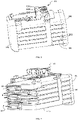
- the cell assembly 13 is disposed in the accommodating space formed by the housing 11. As shown in FIG. 3 , the cell assembly 13 includes one sheet-shaped cell 131 or a plurality of sheet-shaped cells 131. The plurality of sheet-shaped cells 131 are stacked. In some embodiments, the sheet-shaped cell 131 is a flat plate in shape, and the plurality of cells are sequentially stacked in an up-down direction. In other embodiments, the cell 131 may be bent into an arc shape.
- the cell 131 further includes an encapsulation member 1311 configured to encapsulate the cell 131 so as to prevent leakage of compounds in the cell 131. In one embodiment, the encapsulation member 1311 may be, but not limited to, an aluminum plastic film.
- each cell 131 further includes a tab 132 disposed at at least one end of the cell assembly 13 and protruding from the cell 131.
- the cell assembly 13 has an upper surface and a lower surface, a first end surface and a second end surface between the upper surface and the lower surface, and a first side surface and a second side surface on two sides of the first end surface. The first end surface and the second end surface are opposite to each other.
- the tab 132 may be disposed on a left end surface 133 of the cell assembly 13 or on a right end surface 134 of the cell assembly 13.
- the first end surface 133 is the left end surface of the cell assembly 13, and the second end surface 134 is the right end surface of the cell assembly 13.
- tabs 132 are distributed on the left end surface 133 of the cell assembly and other tabs are distributed on the right end surface 134. It is also possible that tabs 132 are distributed on at least one surface or several surfaces, which is not limited herein.
- a plurality of tabs 132 of the cells are mainly connected in series.
- tabs 132 of the cells 131 may be connected in series and then connected in parallel to tabs 132 of other cells 131.
- the plurality of tabs 132 are connected to the circuit board 12 through cables, and the plurality of cells 131 are connected through related circuits of the circuit board 12.
- the tabs 132 are connected to each other through connecting pieces or adapter plates.
- the circuit board 12 is disposed between the upper housing 111 and the cell assembly 13, and the circuit board 12 is electrically connected to the cell assembly 13.
- the circuit board 12 includes a battery pack terminal 121 and a power management module (not illustrated in the figure).
- the power management module is configured to perform power management on the battery pack 10 to implement charging and discharging management of the battery pack 10.
- the battery pack terminal 121 is disposed in the battery pack interface 101 so as to output electrical energy of the battery pack 10.
- the battery pack terminal 121 includes a battery pack positive terminal 1211, a battery pack negative terminal 1212, and a battery pack communication terminal 1213 (referring to FIG. 3 ).
- the battery pack positive terminal 1211 is disposed in the power supply positive interface 1011, and the battery pack negative terminal 1212 is disposed in the power supply negative interface 1012, so as to supply electricity to the power tool 20 which is connected to the battery pack interface 101.
- the battery pack communication terminal 1213 is disposed in the power supply communication interface 1013 to communicate with the power tool 20 which is connected to the battery pack interface 101.
- the battery pack terminal 121 and the tab 132 are connected to output the electrical energy of the battery pack 10, and the circuit board 12 is connected to a positive electrode and a negative electrode of the cell assembly 13 and a positive electrode and a negative electrode of the cell 131.
- the tab 132 is disposed on the left end surface 133 of the cell assembly 13; the tab 132 is connected to a positive wire 124 and a negative wire 125.
- the electrical energy of the battery pack 10 is outputted to the power tool 20 through the tab 132, the positive wire 124, the negative wire 125, and the battery pack terminal 121.
- the tab 132 is connected to the circuit board 12, and the electrical energy of the battery pack 10 is outputted to the power tool 20 through the tab 132, the circuit board 12, and the battery pack terminal 121.
- Spot welding, seam welding, or surface welding is used between the cell 131 and wires and between the cell 131 and other cells 131.
- ultrasonic welding or laser welding is used.
- the cell support member 14 is disposed at two ends of the cell assembly 13, and at least part of the cell support member 14 encapsulates the tab 132.
- the cell support member 14 includes a first support member 141 and a second support member 142.
- the first support member 141 is disposed on the left end surface 133 of the cell assembly 13, and the left end surface 133 is the surface of the cell assembly 13 where the tab 132 is disposed.
- the second support member 142 is disposed on the right end surface 134 of the cell assembly 13, and the right end surface 134 and the left end surface 133 are opposite to each other.
- the cell support member 14 encloses and fixes the tab 132.
- the tab 132 quickly transmits internal heat of the cell 131 out, and the cell assembly 13 quickly transmits internal heat of the cell assembly 13 out through the plurality of tabs 132. Since the cell support member 14 has a preset thermal conductivity (where the thermal conductivity is higher than or equal to 0.6 W/m ⁇ k) and the cell support member 14 is configured to encapsulate the tab 132, the heat of the cell assembly 13 is quickly transmitted out through the cell support member 14 in contact with the tabs 132. Thus, a heat dissipation effect is enhanced.
- the cell support member 14 may extend from the left end surface 133 and the right end surface 134 of the cell assembly 13 to the upper surface, the lower surface, the first side surface, and the second side surface of the cell assembly 13 until the cell assembly 13 is completely enclosed and fixed by the cell support member 14. In other embodiments, the cell support member 14 may enclose the left end surface 133, the right end surface 134, the upper surface, and the lower surface of the cell assembly 13, or the cell support member 14 may enclose the left end surface 133, the right end surface 134, the first side surface, and the second side surface of the cell assembly 13.
- the cell support member 14 is formed at two opposite ends of the cell assembly 13 through glue injection.
- the cell assembly 13 is placed in a mold and the plurality of cells 131 are sequentially stacked from bottom to top in the mold.
- Glue is injected using the mold at the two opposite ends where the tabs 132 of the plurality of cells 131 are located so as to form the cell support member 14 on two sides of the plurality of cells 131. That is, the cell support member 14 is formed on the left end surface 133 and the right end surface 134 of the cell assembly 13 through the glue injection. Then, the cell assembly 13 and the formed cell support member 14 are taken out as a whole.
- the cell support member 14 is formed on the whole outer surface of the cell assembly 13 through the glue injection.
- the cell assembly 13 is placed in the mold, and the cell support member 14 is formed on the whole outer surface of the cell assembly 13 through the glue injection. Then, the cell assembly 13 and the formed cell support member 14 are taken out as a whole.
- the cell support member 14 is a solid-state insulating elastic member, and the cell support member 14 has a compression ratio higher than or equal to 50%.
- the cell support member is an elastic member having elongation at break higher than or equal to 100% and tensile strength higher than or equal to 0.9 N/mm 2 .
- the cell support member 14 has thermal conductivity higher than or equal to 0.6 W/(m.k).
- the cell support member 14 is configured to support the cell assembly 13 to prevent a relative displacement between the plurality of cells 131 due to bumping or shocks so that the plurality of cells 131 or the plurality of tabs 132 are prevented from being squeezed or kinked. Therefore, the cell support member 14 can improve the anti-dropping and shock absorption performance of the battery pack 10 and further improve reliability of the battery pack 10.
- the cell support member 14 is the elastic member and can better adapt to an expansion property of the battery pack 10.
- the cell support member 14 can also improve heat dissipation performance of the battery pack 10, which will be described below in detail in conjunction with an embodiment.
- the cell assembly 13 has a gravimetric energy density within a range of 300 wh/kg to 3500 wh/kg. In one embodiment, the cell assembly 13 has a gravimetric energy density within a range of 1000 wh/kg to 3500 wh/kg. In one embodiment, the cell assembly 13 has a gravimetric energy density within a range of 2600 wh/kg to 3500 wh/kg. In one embodiment, the cell assembly 13 has a gravimetric energy density within a range of 2600 wh/kg to 3000 wh/kg. In one embodiment, the cell assembly 13 has a gravimetric energy density within a range of 300 wh/kg to 500 wh/kg. In one embodiment, the cell assembly 13 has a gravimetric energy density within a range of 400 wh/kg to 600 wh/kg.
- the battery pack 10 further includes a circuit board support member 123 disposed between the circuit board 12 and the cell assembly 13 so as to support and fix the circuit board 12.
- a distance between a lower surface of the circuit board 12 and the upper surface of the cell assembly 13 is greater than or equal to 5 mm.
- the circuit board support member 123 is disposed between the circuit board 12 and the upper surface of the cell assembly 13 or a preset distance is reserved between the circuit board 12 and the upper surface of the cell assembly 13 so that an effect of heating of the cell assembly 13 on the circuit board 12 can be reduced and the battery pack 10 can work normally.
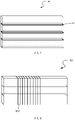
- the battery pack 10 further includes a buffer 15 and the buffer 15 is wound around the upper surface, the first side surface, the lower surface, and the second side surface of the cell assembly 13 so as to fix the cell assembly 13.
- the buffer 15 is foam.
- the foam may be, but not limited to, expanded polyethylene foam.
- the buffer 15 may also be another elastic member having a buffer function.
- the buffer 15 is wound along the surfaces of the cell assembly 13 so as to support and position the battery pack 10 and prevent the battery pack 10 from dropping.
- the battery pack 10 further includes a buffer layer 15'.
- the buffer layer 15' is disposed between adjacent cells 131 and made of the same material as the cell support member 14.
- the buffer layer 15' is made of an elastic material with a compression ratio higher than or equal to 50%, elongation at break higher than or equal to 100%, tensile strength higher than or equal to 0.9 N/mm 2 , and thermal conductivity higher than or equal to 0.6 W/(m ⁇ k).
- the buffer layer 15' disposed between adjacent cells 131 can improve the anti-dropping and shock absorption performance of the battery pack 10 and further improve the reliability of the battery pack 10.
- the buffer layer 15' is an elastic member and can better adapt to the expansion property of the battery pack 10.
- the buffer layer 15' can also enable the temperature of the cell 131 to be uniformly distributed and improve the heat dissipation performance of the battery pack 10.
- the buffer layer 15' is formed between the plurality of cells 131 through the glue injection and integrally formed with the cell support member 14.
- an elastic tape 151 is wound around the upper surface, the first side surface, the lower surface, and the second side surface of the cell assembly 13 so as to bind the cell assembly 13 together, and such an elastic tape 151 also has the function of supporting the cell assembly 13.
- the cell assembly 13 is taken out from the housing 11 and charged. After being charged, the cell assembly 13 will expand. The cell assembly 13 that expands too much cannot be installed into the housing 11 and used again. Therefore, the elastic tape 151 wound around the cell assembly 13 can avoid a risk when the cell assembly 13 that expands too much after being charged is used again.
- the elastic tape 151 may also be wound around the left end surface 133, the right end surface 134, the upper surface, and the lower surface of the cell assembly 13, or the elastic tape 151 may also be wound around the left end surface 133, the right end surface 134, the first side face, and the second side face of the cell assembly 13, so as to enclose the tabs 132 and bind the cell assembly 13 together.
- Such an elastic tape 151 also has the function of supporting the cell assembly 13 to prevent the relative displacement between the plurality of cells 131 due to bumping or shocks so that the plurality of cells 131 or the plurality of tabs 132 are prevented from being squeezed or kinked.
- the elastic tape 151 can improve the anti-dropping and shock absorption performance of the battery pack 10 and further improve the reliability of the battery pack 10.
- the elastic tape 151 is the elastic member and can better adapt to the expansion property of the battery pack 10.
- Table 1 shows data of the battery pack 10 provided with the cell support member 14 for a three-meter drop test.
- Table 1 Before Drop Test After Drop Test Physical Quantity Voltage Internal Resistance Voltage Internal Resistance Value 21 V 16.0 m ⁇ 20.855 16.1 m ⁇
- the voltage and internal resistance of the battery pack 10 are measured and recorded as 21 V and 16.0 m ⁇ , respectively. After six drop tests are performed, a surface temperature of the battery pack 10 has no abnormality within two hours, and the voltage and internal resistance of the battery pack 10 are measured again. The voltage is 20.855 V and the internal resistance is 16.1 m ⁇ . After the drop test, the voltage and internal resistance of the battery pack 10 are hardly changed.
- the cell support member 14 better supports and positions the battery pack 10 and improves the anti-dropping and shock absorption performance of the battery pack 10.
- FIG. 9 is a comparison graph of a temperature rise test for the battery pack 10 and a cylindrical lithium battery pack in the related art, temperature rises of the two battery packs are compared, where the two battery packs discharge at a constant current of 40 A. After discharging at the constant current for 600s, the cylindrical lithium battery pack has a maximum temperature of 83.15 °C and the battery pack 10 has a maximum temperature of 56.15 °C. In this process, an average output voltage of the cylindrical lithium battery pack is 48 V, and an average output voltage of the battery pack 10 is 50.3 V.
- the battery pack 10 has better heat dissipation performance than the cylindrical lithium battery pack in the related art.
- the encapsulation member 1311 of the cell 131 is conducive to heat dissipation of the battery pack 10.
- the average voltage outputted by the battery pack 10 is 2.3 V higher than the average voltage outputted by the cylindrical lithium battery pack, that is, the battery pack 10 has higher output power at the same load current.
- the temperature rise test is performed on the battery pack 10.
- Samples 1, 2, and 3 are prepared, which are a battery pack without a cell support member, a battery pack completely covered by the cell support member, and a battery pack with side surfaces covered by the cell support member, respectively.
- the temperature rise test includes steps below. At a temperature of 25 °C ⁇ 2 °C, the samples 1, 2, and 3 are charged at a constant current of 2C (C refers to a charging/discharging rate) to 21 V. At a constant voltage of 21 V, the samples 1, 2 and 3 are charged until the current is reduced to 0.02C. The samples 1, 2, and 3 stand for 1 hour. The samples 1, 2, and 3 discharge to 15 V at a constant current of 10C. During discharging, the temperatures of the battery packs are tested and the temperature of each sample battery pack is measured.
- the battery pack 10 with the cell support member 14 has better heat dissipation performance.
- the cell support member 14 is conducive to heat dissipation of the cell assembly 13 to prevent the battery pack 10 from being damaged due to overheating.
- the battery pack 10 further includes a first sensor 16.
- the first sensor 16 is electrically connected to the circuit board 12 and configured to detect a temperature of the cell assembly 13. In one embodiment, the first sensor 16 is configured to detect a temperature of the cell 131, and when the temperature of the cell 131 exceeds a threshold, the battery pack 10 stops outputting the electrical energy. In one embodiment, the first sensor 16 is disposed on a side of the tab 132 facing towards the cell support member 14. In other embodiments, the first sensor 16 may also be placed on the cell assembly 13. One first sensor 16 or a plurality of first sensors 16 may be disposed. The first sensor 16 may be a thermistor, a thermocouple, a digital temperature sensor, or the like.
- the first sensor 16 is disposed so that the cell 131 can be prevented from too high a temperature and safety problems can be avoided during use.
- the battery pack 10 further includes a second sensor 17, a switch 18, and a controller 19.
- the second sensor 17 is configured to detect a parameter related to leakage of the cell 131; the switch 18 is configured to make or break an electrical connection between the tab 132 and the battery pack terminal 121; and the controller 19 is configured to output a control signal for turning off the switch 18 so as to break the electrical connection between the battery pack terminal 121 and the tab 132 in the case where the second sensor 17 detects that the parameter related to the leakage of the cell 131 is greater than or equal to a parameter threshold.
- the second sensor 17 is a pressure sensor 171.
- the pressure sensor 171 is configured to detect an amount of deformation of the cell 131.
- the pressure sensor 171 is configured to detect an amount of deformation of the encapsulation member 1311.
- the pressure sensor 17 sends a signal to the controller 19.
- the pressure sensor 171 is disposed between adjacent cells 131 so that the pressure sensor 171 detects the amount of deformation with higher sensitivity.
- the pressure sensors 171 may be disposed on the upper surface of the cell assembly 13, on the lower surface of the cell assembly 13, and between adjacent cells 131 of the cell assembly 13, or the pressure sensor 171 may be disposed at any position of the upper surface of the cell assembly 13, the lower surface of the cell assembly 13, and a position between adjacent cells 131 of the cell assembly 13.
- the pressure sensor 171 may be one of or a combination of pressure sensors such as a semiconductor piezoresistive sensor and an electrostatic capacitive pressure sensor.
- the switch 18 is electrically connected between the tab 132 and the battery pack terminal 121 and configured to make or break the electrical connection between the tab 132 and the battery pack terminal 121.
- the switch 18 is controlled by the controller 19 to be turned on or off.
- the switch 18 is disposed on the circuit board 12.
- the switch 18 may be an electronic switch such as a metal-oxide-semiconductor field-effect transistor (MOSFET), an insulated-gate bipolar transistor (IGBT), or a relay. In one embodiment, the switch 18 may also be a mechanical switch.
- the controller 19 is electrically connected to the pressure sensor 171 and the switch 18 separately.
- the controller 19 receives the signal from the pressure sensor 171 and turns off the switch 18 when the encapsulation member 1311 expands and the pressure sensor 171 detects that the amount of deformation of the encapsulation member 1311 exceeds the threshold so that the battery pack 10 stops outputting the electrical energy.
- the mechanical switch is used as the switch 18 and connected between the tab 132 and the battery pack terminal 121.
- the mechanical switch is configured to make or break the electrical connection between the tab 132 and the battery pack terminal 121.
- the mechanical switch is ejected so that the battery pack 10 stops outputting the electrical energy.
- the second sensor 17 is a gas sensor 172 configured to detect a gas concentration in the housing 11.
- the gas sensor 172 sends a signal to the controller 19 when the gas sensor 172 detects that the gas concentration in the housing 11 is higher than or equal to a concentration threshold.
- the gas sensor 172 is disposed at a position close to the cell assembly 13 in the housing 11 of the battery pack so that the gas sensor 172 detects the gas concentration with higher sensitivity. In other embodiments, the gas sensor 172 may be disposed on any surface of the cell assembly 13.
- the controller 19 is electrically connected to the gas sensor 172 and the switch 18 separately.
- the controller 19 receives the signal from the gas sensor 172 and turns off the switch 18 to break the electrical connection between the tab 132 and the battery pack terminal 121 when the gas sensor 172 detects that the gas concentration in the housing 11 is higher than or equal to the concentration threshold.
- the gas sensor 172 detects that the gas concentration in the housing 11 is higher than or equal to the concentration threshold, and the gas sensor sends the signal to the controller 19.
- the controller 19 receives the signal from the gas sensor 172 and turns off the switch 18 to break the electrical connection between the tab 132 and the battery pack terminal 121.
- the second sensor 17 is a voltage sensor 173.
- the voltage sensor 173 is configured to detect a voltage of the cell 131.
- the voltage sensor 173 is disposed on the circuit board 12, the voltage sensor 173 is electrically connected to the controller 19, and when the voltage sensor 173 detects that the voltage of the cell 131 quickly decreases, the voltage sensor 173 sends a signal to the controller 19.
- the voltage sensor 173 may also be disposed on the tab 132.
- the controller 19 is electrically connected to the voltage sensor 173 and the switch 18 separately.
- the controller 19 receives the signal from the voltage sensor 173 and turns off the switch 18 to break the electrical connection between the tab 132 and the battery pack terminal 121.
- the voltage of the cell 131 decreases quickly.
- the voltage sensor 173 detects that the rate at which the voltage of the cell 131 decreases is higher than or equal to the rate threshold, the voltage sensor 173 sends the signal to the controller 19.
- the controller 19 receives the signal from the voltage sensor 173 and turns off the switch 18 to break the electrical connection between the tab 132 and the battery pack terminal 121.
- the battery pack 10 is provided with the second sensor 17 so that a change of an internal parameter of the battery pack 10 can be detected.
- the battery pack 10 can stop outputting the electrical energy in time when the encapsulation member 1311 is damaged so that safety performance of the battery pack 10 is improved.
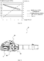
- FIG. 16 is a comparison graph illustrating discharge curves of the battery pack 10 in this embodiment and the cylindrical lithium battery pack in the related art
- the battery packs discharge at a rate of 10C, where 10C represents a current density when the battery pack completely discharges for 0.1 hours.
- 10C represents a current density when the battery pack completely discharges for 0.1 hours.
- the battery pack 10 in this embodiment can keep discharging for more than 100s while the cylindrical lithium battery pack in the related art can keep discharging for merely 6s. Therefore, at the same discharging rate, the battery pack 10 in this embodiment has a higher voltage and higher efficiency.
- FIG. 17 illustrates a power tool and a battery pack 10 which is applicable to the power tool so as to supply electricity to the power tool.
- the power tool is a hand-propelled snow thrower 21.
- the battery pack 10 supplies electrical energy to the snow thrower 21.
- the snow thrower 21 includes a handle device 211, a housing assembly 212, an auger 213, a snow throwing device 214, a motor 215, an angle adjusting device 216, and wheels 217.
- the handle device 211 is operated by a user, and the housing assembly 212 accommodates or fixes the motor 215.
- the auger 213 is a functional element of the snow thrower 21.
- the motor 215 drives the auger 30 to rotate to implement a snow sweeping function.
- the battery pack 10 is electrically connected to the motor 215 to supply electric power to the motor 215.
- the wheels 217 rotate relative to the housing assembly 212 so that the snow thrower 21 travels on the ground.
- the snow throwing device 214 is configured to change a movement path of snow to guide the snow to a distant place.
- a body 22 implements the snow sweeping function.
- the housing assembly 212, the auger 213, and the motor 215 form the body of the snow thrower 21.
- the battery pack 10 is detachably connected to the body.
- the battery pack 10 may be a single battery pack or may be a plurality of battery packs.
- the housing assembly 212 includes a body housing and further includes a battery compartment cover 2121 and a battery compartment body 2122.
- the battery compartment cover 2121 and the battery compartment body 2122 make encirclement to form a battery compartment for accommodating the battery pack 10.
- at least part of the battery compartment body 2122 is accommodated in an accommodating cavity formed by the body housing.
- the battery compartment includes two cavities divided by the battery compartment body 2122, that is, a first cavity 2123a and a second cavity 2123b, and two battery packs 10 are respectively mounted into the first cavity 2123a and the second cavity 2123b.
- the battery pack discharges at a rate of 5C after being placed for 12 hours at a temperature of -20 °C, where 5C represents a current intensity when the battery pack completely discharges for 1/5 hours.
- the cylindrical lithium battery pack in the related art supplies electricity for about 15s and then enters undervoltage protection (where an undervoltage critical value is set to 2.75 V). Therefore, the cylindrical lithium battery pack in the related art cannot output electrical energy after entering the undervoltage protection.
- the battery pack 10 in this embodiment can keep discharging.
- the cell assembly 13 can discharge at a rate of 5C at an ambient temperature T, where -22 °C ⁇ T ⁇ -15 °C, and 5C represents the current intensity when the cell assembly completely discharges for 1/5 hours.
- the cell assembly 13 can discharge at the rate of 5C at the ambient temperature T, where -22 °C ⁇ T ⁇ -18 °C. In other embodiments, the cell assembly 13 can discharge at a rate higher than or equal to 5C.
- the battery pack 10 in this embodiment can work in a low-temperature environment and supply electricity to a power tool which needs to work under a low-temperature condition, thus overcoming the defect of the cylindrical lithium battery pack in the related art that an electrical energy output is affected due to too low an ambient temperature in the low-temperature environment.
- the battery pack 10 can also supply electrical energy to a mower 22.
- the mower 22 includes a frame 221, a seat 222, a mowing unit 223, a walking unit 224, an operating device 225, a power supply device 226, and a control unit (not illustrated in the figure).
- the battery pack 10 is disposed in the power supply device 226. Referring to FIG. 19
- a rotational speed of the mower 22 powered by the battery pack 10 in this embodiment is 7.4% higher than a rotational speed of the mower 22 powered by the cylindrical lithium battery pack in the related art; when the output current of the battery pack 10 is 72 A, the rotational speed of the mower 22 powered by the battery pack 10 in this embodiment is 13.3% higher than the rotational speed of the mower 22 powered by the cylindrical lithium battery pack. Therefore, under a heavy load condition, the battery pack 10 is more advantageous and has a higher rotational speed and higher output power than the cylindrical lithium battery pack.
- a power tool is a blower 23.
- the blower 23 includes a motor 231 having a stator and a rotor; an output shaft driven by the rotor of the motor 231; a fan 232 connected to the output shaft and driven by the motor 231 to rotate; and a housing 233 and a battery pack 10.
- the battery pack 10 includes a battery group.
- the battery group includes one sheet-shaped cell or a plurality of sheet-shaped cells that are stacked.
- the battery group has an upper surface, a lower surface, a front surface, a rear surface, a first side surface, and a second side surface.
- One tab or a plurality of tabs are disposed on the first side surface of the battery group.
- a cell support member group is further included.
- the cell support member group includes at least one cell support member.
- the at least one cell support member at least encapsulates the one tab or the plurality of tabs on the first side surface of the battery group.
- the at least one cell support member is made of an elastic material.
- the cell support member has a compression ratio higher than or equal to 50%.
- the cell support member has elongation at break higher than or equal to 100%.
- the cell support member has tensile strength higher than or equal to 0.9 N/mm 2 .
- the cell support member has thermal conductivity higher than or equal to 0.6 W/(m.k).
- the power tool further includes a first sensor configured to detect a temperature of the sheet-shaped cell and disposed on a side of the tab facing towards the cell support member.
- the power tool further includes a second sensor configured to detect a parameter related to leakage of the sheet-shaped cell and disposed in the cell assembly.
- the power tool further includes a battery pack terminal electrically connected to the tab.
- the power tool further includes a controller configured to output a control signal for turning off the switch so as to break an electrical connection between the battery pack terminal and the tab in the case where the second sensor detects that the parameter related to the leakage of the cell is greater than or equal to a parameter threshold.
- a power tool is a handheld power tool.
- the handheld power tool includes a motor having a stator and a rotor; an output shaft driven by the rotor of the motor; a tool accessory shaft configured to support a tool accessory; a transmission device configured to connect the output shaft to the tool accessory shaft so as to transmit torque outputted from the motor to the tool accessory; and a battery pack connected to the handheld power tool.
- the battery pack includes a battery group.
- the battery group includes one sheet-shaped cell or a plurality of sheet-shaped cells that are stacked.
- the battery group has an upper surface, a lower surface, a front surface, a rear surface, a first side surface, and a second side surface.
- the support member group includes a first support member and a second support member.
- the first support member is disposed on the first side surface of the battery group and extends to the upper surface, the lower surface, the front surface, and the rear surface of the battery group.
- the second support member is disposed on the second side surface of the battery group and extends to the upper surface, the lower surface, the front surface, and the rear surface of the battery group.
- the first support member and the second support member are each made of an elastic material.
- a power tool is a handheld power tool.
- the handheld power tool includes a motor having a stator and a rotor; an output shaft driven by the rotor of the motor; a tool accessory shaft configured to support a tool accessory; a transmission device configured to connect the output shaft to the tool accessory shaft so as to transmit torque outputted from the motor to the tool accessory; and a battery pack connected to the handheld power tool.
- the battery pack includes a battery group.
- the battery group includes one sheet-shaped cell or a plurality of sheet-shaped cells that are stacked.
- the battery group has an upper surface, a lower surface, a front surface, a rear surface, a first side surface, and a second side surface.
- the support member group includes a first support member and a second support member.
- the first support member is disposed on the first side surface of the battery group and extends to at least one or more surfaces among the upper surface, the lower surface, the front surface, and the rear surface of the battery group.
- the second support member is disposed on the second side surface of the battery group and extends to at least one or more surfaces among the upper surface, the lower surface, the front surface, and the rear surface of the battery group.
- the first support member and the second support member are each made of an elastic material.
- a power tool is a handheld power tool.
- the handheld power tool includes a motor having a stator and a rotor; an output shaft driven by the rotor of the motor; a tool accessory shaft configured to support a tool accessory; a transmission device configured to connect the output shaft to the tool accessory shaft so as to transmit torque outputted from the motor to the tool accessory; and a battery pack connected to the handheld power tool.
- the battery pack includes a battery group.
- the battery group includes one sheet-shaped cell or a plurality of sheet-shaped cells that are stacked.
- the battery group has an upper surface, a lower surface, a front surface, a rear surface, and a first side surface. One first tab or a plurality of first tabs are disposed on the first side surface.
- a support member group is further included.
- the support member group includes at least one support member.
- the at least one support member is made of an elastic material.
- a power tool is a handheld power tool.
- the handheld power tool includes a motor having a stator and a rotor; an output shaft driven by the rotor of the motor; a tool accessory shaft configured to support a tool accessory; a transmission device configured to connect the output shaft to the tool accessory shaft so as to transmit torque outputted from the motor to the tool accessory; a battery pack connected to the handheld power tool; and a support member group.
- the battery pack includes a battery group.
- the battery group includes one sheet-shaped cell or a plurality of sheet-shaped cells that are stacked.
- One first tab or a plurality of first tabs are disposed on a first side surface of the battery group.
- the support member group includes at least one support member.
- the at least one support member at least encapsulates the one first tab or the plurality of first tabs on the first side surface of the battery group.
- the at least one support member is made of an elastic material.
- a power tool is a handheld power tool.
- the handheld power tool includes a motor having a stator and a rotor; an output shaft driven by the rotor of the motor; a tool accessory shaft configured to support a tool accessory; a transmission device configured to connect the output shaft to the tool accessory shaft so as to transmit torque outputted from the motor to the tool accessory; and a battery pack connected to the handheld power tool.
- the battery pack includes a battery group.
- the battery group includes one sheet-shaped cell or a plurality of sheet-shaped cells that are stacked.
- the battery group has an upper surface, a lower surface, a front surface, a rear surface, a first side surface, and a second side surface.
- the support member group includes at least one support member.
- the at least one support member is disposed on the first side surface of the battery group and extends to at least one or more surfaces among the upper surface, the lower surface, the front surface, and the rear surface.
- the at least one support member is made of an elastic material.
- a power tool in one embodiment, includes a motor having a stator and a rotor; an output shaft driven by the rotor of the motor; a fan connected to the output shaft and driven by the motor to rotate; and a battery pack interface configured to connect a battery pack.
- the battery pack includes a battery group.
- the battery group includes one sheet-shaped cell or a plurality of sheet-shaped cells that are stacked.
- the battery group has an upper surface, a lower surface, a front surface, a rear surface, a first side surface, and a second side surface.
- One first tab or a plurality of first tabs are disposed on the first side surface, and one second tab or a plurality of second tabs are disposed on the second side surface.
- a support member group is further included.
- the support member group includes a first support member and a second support member.
- the first support member is disposed on the first side surface of the battery group and extends to the upper surface, the lower surface, the front surface, and the rear surface of the battery group.
- the second support member is disposed on the second side surface of the battery group and extends to the upper surface, the lower surface, the front surface, and the rear surface of the battery group.
- the first support member and the second support member are each made of an elastic material.
- a power tool in one embodiment, includes a motor having a stator and a rotor; an output shaft driven by the rotor of the motor; a fan connected to the output shaft and driven by the motor to rotate; and a battery pack interface configured to connect a battery pack.
- the battery pack includes a battery group.
- the battery group includes one sheet-shaped cell or a plurality of sheet-shaped cells that are stacked.
- the battery group has an upper surface, a lower surface, a front surface, a rear surface, a first side surface, and a second side surface.
- One first tab or a plurality of first tabs are disposed on the first side surface, and one second tab or a plurality of second tabs are disposed on the second side surface.
- a support member group is further included.
- the support member group includes a first support member and a second support member.
- the first support member is disposed on the first side surface of the battery group and extends to at least one or more surfaces among the upper surface, the lower surface, the front surface, and the rear surface of the battery group.
- the second support member is disposed on the second side surface of the battery group and extends to at least one surface or more surfaces among the upper surface, the lower surface, the front surface, and the rear surface of the battery group.
- the first support member and the second support member are each made of an elastic material.
- a power tool in one embodiment, includes a motor having a stator and a rotor; an output shaft driven by the rotor of the motor; a fan connected to the output shaft and driven by the motor to rotate; and a battery pack interface configured to connect a battery pack.
- the battery pack includes a battery group.
- the battery group includes one sheet-shaped cell or a plurality of sheet-shaped cells that are stacked.
- the battery group has an upper surface, a lower surface, a front surface, a rear surface, a first side surface, and a second side surface.
- One first tab or a plurality of first tabs are disposed on the first side surface.
- a support member group is further included.
- the support member group includes at least one support member.
- the at least one support member is disposed on the first side surface of the battery group and extends to at least one or more surfaces among the upper surface, the lower surface, the front surface, and the rear surface of the battery group.
- the at least one support member is made of an elastic material
- a power tool in one embodiment, includes a motor having a stator and a rotor; an output shaft driven by the rotor of the motor; a fan connected to the output shaft and driven by the motor to rotate; and a battery pack interface configured to connect a battery pack.
- the battery pack includes a battery group.
- the battery group includes one sheet-shaped cell or a plurality of sheet-shaped cells that are stacked.
- the battery group has an upper surface, a lower surface, a front surface, a rear surface, and a first side surface.
- One first tab or a plurality of first tabs are disposed on the first side surface.
- a support member group is further included.
- the support member group includes at least one support member.
- the at least one support member is made of an elastic material.
- a power tool in one embodiment, includes a motor having a stator and a rotor; an output shaft driven by the rotor of the motor; a fan connected to the output shaft and driven by the motor to rotate; and a battery pack interface configured to connect a battery pack.
- the battery pack includes a battery group.
- the battery group includes one sheet-shaped cell or a plurality of sheet-shaped cells that are stacked.
- One first tab or a plurality of first tabs are disposed at least on a first side surface of the battery group.
- a support member group is further included.
- the support member group includes at least one support member.
- the at least one support member at least encapsulates the one first tab or the plurality of first tabs on the first side surface of the battery group.
- the at least one support member is made of an elastic material.
- the battery pack is detachably connected to the battery pack interface.
- a power tool is a mower.
- the mower includes a body; at least one driving wheel or a driving wheel group supported by the body; a driving device or an energy storage device configured to supply torque to the at least one driving wheel or the driving wheel group; and a battery pack interface configured to connect a battery pack.
- the battery pack includes a battery group.
- the battery group includes one sheet-shaped cell or a plurality of sheet-shaped cells that are stacked.
- the battery group has an upper surface, a lower surface, a front surface, a rear surface, a first side surface, and a second side surface.
- One first tab or a plurality of first tabs are disposed on the first side surface, and one second tab or a plurality of second tabs are disposed on the second side surface.
- a support member group is further included.
- the support member group includes a first support member and a second support member.
- the first support member is disposed on the first side surface of the battery group and extends to the upper surface, the lower surface, the front surface, and the rear surface of the battery group.
- the second support member is disposed on the second side surface of the battery group and extends to the upper surface, the lower surface, the front surface, and the rear surface of the battery group.
- the first support member and the second support member are each made of an elastic material.
- the battery pack is detachably connected to the battery pack interface.
- a power tool is a mower.
- the mower includes a body; at least one driving wheel or a driving wheel group supported by the body; a driving device or an energy storage device configured to supply torque to the at least one driving wheel or the driving wheel group; and a battery pack interface configured to connect a battery pack.
- the battery pack includes a battery group.
- the battery group includes one sheet-shaped cell or a plurality of sheet-shaped cells that are stacked.
- the battery group has an upper surface, a lower surface, a front surface, a rear surface, a first side surface, and a second side surface.
- One first tab or a plurality of first tabs are disposed on the first side surface, and one second tab or a plurality of second tabs are disposed on the second side surface.
- a support member group is further included.
- the support member group includes a first support member and a second support member.
- the first support member is disposed on the first side surface of the battery group and extends to at least one or more surfaces among the upper surface, the lower surface, the front surface, and the rear surface.
- the second support member is disposed on the second side surface of the battery group and extends to at least one or more surfaces among the upper surface, the lower surface, the front surface, and the rear surface.
- the first support member and the second support member are each made of an elastic material.
- a power tool is a mower.
- the mower includes a body; at least one driving wheel or a driving wheel group supported by the body; a driving device or an energy storage device configured to supply torque to the at least one driving wheel or the driving wheel group; and a battery pack interface configured to connect a battery pack.
- the battery pack includes a battery group.
- the battery group includes one sheet-shaped cell or a plurality of sheet-shaped cells that are stacked.
- the battery group has an upper surface, a lower surface, a front surface, a rear surface, a first side surface, and a second side surface.
- One first tab or a plurality of first tabs are disposed on the first side surface.
- a support member group is further included.
- the support member group includes at least one support member.
- the at least one support member is disposed on the first side surface of the battery group and extends to at least one or more surfaces among the upper surface, the lower surface, the front surface, and the rear surface.
- the at least one support member is made of
- a power tool is a mower.
- the mower includes a body; at least one driving wheel or a driving wheel group supported by the body; a driving device or an energy storage device configured to supply torque to the at least one driving wheel or the driving wheel group; and a battery pack interface configured to connect a battery pack.
- the battery pack includes a battery group.
- the battery group includes one sheet-shaped cell or a plurality of sheet-shaped cells that are stacked.
- the battery group has an upper surface, a lower surface, a front surface, a rear surface, and a first side surface.
- One first tab or a plurality of first tabs are disposed on the first side surface.
- a support member group is further included.
- the support member group includes at least one support member.
- the at least one support member is made of an elastic material.
- a power tool is a mower.
- the mower includes a body; at least one driving wheel or a driving wheel group supported by the body; a driving device or an energy storage device configured to supply torque to the at least one driving wheel or the driving wheel group; and a battery pack interface configured to connect a battery pack.
- the battery pack includes a battery group.
- the battery group includes one sheet-shaped cell or a plurality of sheet-shaped cells that are stacked.
- One first tab or a plurality of first tabs are disposed at least on a first side surface of the battery group.
- a support member group is further included.
- the support member group includes at least one support member.
- the at least one support member at least encapsulates the one first tab or the plurality of first tabs on the first side surface of the battery group.
- the at least one support member is made of an elastic material.
Landscapes
- Chemical & Material Sciences (AREA)
- Chemical Kinetics & Catalysis (AREA)
- Electrochemistry (AREA)
- General Chemical & Material Sciences (AREA)
- Engineering & Computer Science (AREA)
- Manufacturing & Machinery (AREA)
- Life Sciences & Earth Sciences (AREA)
- Biophysics (AREA)
- Computer Hardware Design (AREA)
- Materials Engineering (AREA)
- Battery Mounting, Suspending (AREA)
Abstract
Description
- This application claims priority to
Chinese Patent Application No. 201910534991.4 filed Jun. 20, 2019 Chinese Patent Application No. 201910829581.2 filed Sep. 03, 2019 - The present application relates to the technical field of batteries, for example, a battery pack and a combination of a power tool and the battery pack.
- Battery packs are used as power sources for more and more power tools based on the need for portability.
- In the related art, a battery pack for supplying electricity to a power tool mostly uses cylindrical lithium cells. A plurality of cylindrical lithium cells are connected in series and in parallel to ensure a sufficient electrical energy output so as to improve endurance of the power tool.
- On the one hand, the cylindrical lithium cell generally uses a rigid metal as a housing, which results in a large mass of the whole battery pack. A user needs to overcome relatively strong gravity to operate a machine when using the battery pack, affecting user experience.
- From 2009 to 2013, TTI provided a rechargeable lithium battery pack for a power tool in patent publications such as
US7554290 ,US7557535 ,US7944173 ,US7999510 ,US8207702 ,US8269459 , andUS8450971 . The lithium battery pack can generate an average charging current higher than or equal to 20 amps, and such a battery pack can be repeatedly used by being charging so that the following problem is solved: disposable battery packs of power tools need to be frequently replaced and the same battery pack cannot be repeatedly used in the industry. Moreover, merely one battery pack was enough to supply matching output power required by the power tool in the industry at that time. - With the development of the power tool industry, power tools increasingly need power supply devices which can provide at least one of endurance or a high-power output of electrical energy. From 2014 to 2015, Makita provided two rechargeable lithium battery packs for different power tools in patent publications such as
WO2014119175A1 ,WO2014119174A1 ,WO2014119188A1 , andWO2015156170A1 . The two rechargeable lithium battery packs can be connected to each other in parallel or in series to improve the endurance or output power of the battery packs. However, though a product using the two rechargeable lithium battery packs solves the problem about the output power or endurance, it will be very cumbersome for the user to operate a power tool using the two rechargeable lithium battery packs. In addition, the user has a poor operation experience and is easy to get tired when operating the power tool for a long time. - On the other hand, the cylindrical lithium cell in a low-temperature environment has the defect that an electrical energy output is affected due to too low an ambient temperature. Therefore, a power tool using the battery pack in the related art has greatly reduced performance when used in the low-temperature environment.
- The present application provides a battery pack and a combination of a power tool and the battery pack, where the battery pack has a relatively small mass and better discharge performance at a low temperature.
- One embodiment provides a battery pack. The battery pack includes a housing, a cell assembly, a cell support member, a first sensor, and a second sensor. The cell assembly is disposed in the housing; and the cell support member is at least configured to support the cell assembly. The cell assembly includes a plurality of cells which are sheet-shaped, the plurality of cells are stacked, and a cell among the plurality of cells includes an encapsulation member configured to encapsulate the cell and a tab disposed at each of two ends of the cell assembly and protruding from the cell. The cell support member is disposed on opposite sides in a length direction of the cell assembly to encapsulate the tab. The cell assembly is configured to be capable of discharging at a rate higher than or equal to 5C at an ambient temperature T, where -22 °C ≤ T ≤ -15 °C, and 5C represents a current intensity when a battery completely discharges for 1/5 hours, and the cell assembly has a gravimetric energy density higher than or equal to 300 wh/kg. The first sensor is configured to detect a temperature of the cell and disposed on a side of the tab facing towards the cell support member. The second sensor is configured to detect a parameter related to leakage of the cell and disposed in the cell assembly.
- One embodiment provides a battery pack. The battery pack includes a housing, a cell assembly, and a cell support member. The cell assembly is disposed in the housing; and the cell support member is at least configured to support the cell assembly. The cell assembly includes a plurality of cells which are sheet-shaped, the plurality of cells are stacked, and a cell among the plurality of cells includes an encapsulation member configured to encapsulate the cell and a tab disposed at each of two ends of the cell assembly and protruding from the cell. The cell support member is disposed at the two ends of the cell assembly, and at least part of the cell support member encapsulates the tab. The cell assembly is configured to be capable of discharging at a rate of 5C at an ambient temperature T, where -22 °C ≤ T ≤ -15 °C, and 5C represents a current intensity when a battery completely discharges for 1/5 hours, and the cell assembly has a gravimetric energy density higher than or equal to 300 wh/kg.
- One embodiment provides a combination of a power tool and a battery pack. The combination includes the power tool and the battery pack. The power tool includes a tool body and a tool interface and a tool matching portion disposed on the tool body. The battery pack is provided with a battery pack interface and a battery pack coupling portion, where the battery pack interface is configured to be adapted to the tool interface so as to supply electricity to the power tool, and the battery pack coupling portion is detachably connected to the tool matching portion. The battery pack further includes a housing, a cell assembly, and a cell support member. The cell assembly is disposed in the housing; and the cell support member is at least configured to support the cell assembly. The cell support member is made of an elastic material with a compression ratio higher than or equal to 50%. The cell assembly includes a plurality of cells which are sheet-shaped, the plurality of cells are stacked, and a cell among the plurality of cells includes an encapsulation member configured to encapsulate the cell and a tab disposed at each of two ends of the cell assembly and protruding from the cell. The cell support member is disposed at the two ends of the cell assembly and at least part of the cell support member encapsulates the tab. The cell assembly is configured to be capable of discharging at a rate of 5C at an ambient temperature T, where -22 °C ≤ T ≤ -15 °C, and 5C represents a current intensity when a battery completely discharges for 1/5 hours.
- One embodiment provides a combination of a power tool and a battery pack. The combination includes the power tool and the battery pack. The battery pack is connected to the power tool. The battery pack includes a housing, a cell assembly, and a cell support member group. The cell assembly is disposed in the housing. The cell assembly includes a plurality of cells which are sheet-shaped, the plurality of cells are stacked, and a cell among the plurality of cells includes an encapsulation member configured to encapsulate the cell and a tab disposed at at least one end of the cell assembly and protruding from the cell. The cell support member group includes at least one cell support member. The cell support member is configured to at least support the cell assembly. The cell support member is disposed at the at least one end of the cell assembly and at least part of the cell support member encapsulates the tab. The cell assembly is configured to be capable of discharging at a rate higher than or equal to 5C at an ambient temperature T, where -22 °C ≤ T ≤ -15 °C, and 5C represents a current intensity when a battery completely discharges for 1/5 hours.
-
-
FIG. 1 is a schematic view illustrating a battery pack and power tools; -
FIG. 2 is a structure view of a battery pack according to an embodiment; -
FIG. 3 is an internal structure view of the battery pack inFIG. 1 with a housing removed; -
FIG. 4 is a structure view of the battery pack inFIG. 3 with a first support member removed; -
FIG. 5 is an internal structure view of a battery pack with a housing removed according to an embodiment; -
FIG. 6 is a structure view of a battery pack including a buffer according to an embodiment; -
FIG. 7 is a structure view of a battery pack including a buffer according to an embodiment; -
FIG. 8 is a structure view of a battery pack including an elastic tape according to an embodiment; -
FIG. 9 is a graph of a temperature rise test for a battery pack according to an embodiment and a cylindrical lithium battery pack in the related art; -
FIG. 10 is a graph of a temperature rise test for battery packs with/without a support assembly according to an embodiment; -
FIG. 11 is a block diagram of a protection circuit of a battery pack according to an embodiment; -
FIG. 12 is a schematic diagram illustrating a position of a pressure sensor according to an embodiment; -
FIG. 13 is a block diagram of a protection circuit of a battery pack according to an embodiment; -
FIG. 14 is a schematic view illustrating a position of a gas sensor according to an embodiment; -
FIG. 15 is a block diagram of a protection circuit of a battery pack according to an embodiment; -
FIG. 16 is a graph illustrating discharge curves of a battery pack according to an embodiment and a cylindrical lithium battery pack in the related art; -
FIG. 17 is a schematic view of a battery pack and a hand-propelled snow thrower; -
FIG. 18 is a graph illustrating discharge curves of a battery pack according to an embodiment and a cylindrical lithium battery pack in the related art at a low temperature; -
FIG. 19 is a schematic view of a mower; -
FIG. 20 is a graph of a mechanical performance test for a mower according to an embodiment; and -
FIG. 21 is a schematic view of a blower. -
FIG. 1 illustrates apower tool 20 and abattery pack 10 which is applicable to thepower tool 20 and supplies electricity to thepower tool 20. A voltage of thebattery pack 10 is typically 10.8 V, 24 V, 36 V, 48 V, 56 V, or 80 V, which is not limited herein. Thebattery pack 10 has a capacity higher than or equal to 2Ah. InFIG. 1 , thepower tool 20 is an electric drill. Though a sander is involved in this embodiment, it is to be understood that the present application is not limited to disclosed embodiments, and the battery pack is applicable to other types of power tools, including, but not limited to, ahammer 30, asander 40, an angle grinder, the electric drill, an electric wrench, and an electric saw. - The
power tool 20 includes atool body 201 and atool interface 2011 and atool matching portion 2012 disposed on thetool body 201. Thebattery pack 10 is provided with abattery pack interface 101 and a batterypack coupling portion 102. Thebattery pack interface 101 is adapted to thetool interface 2011 so as to supply electricity to thepower tool 20. The batterypack coupling portion 102 can be detachably connected to thetool matching portion 2012 so as to enable thebattery pack 10 to supply electricity to thepower tool 20. - In the following description, directions "up", "down", "front", and "back" are described using directions indicated by arrows in
FIG. 2 . - Referring to
FIGS. 1 to 4 , thebattery pack 10 includes ahousing 11, acircuit board 12, acell assembly 13, and acell support member 14. - The
housing 11 includes anupper housing 111 and alower housing 112. Theupper housing 111 and thelower housing 112 are assembled to form an accommodating space for fixing and accommodating thecell assembly 13. Thebattery pack interface 101 is formed on one surface of thehousing 11. Thebattery pack interface 101 includes a power supplypositive interface 1011, a power supplynegative interface 1012, and a power supply communication interface 1013 (referring toFIG. 1 ). Thebattery pack 10 supplies electrical energy to thepower tool 20 through the power supplypositive interface 1011 and the power supplynegative interface 1012. Thebattery pack 10 communicates with thepower tool 20 through the powersupply communication interface 1013. - The
cell assembly 13 is disposed in the accommodating space formed by thehousing 11. As shown inFIG. 3 , thecell assembly 13 includes one sheet-shapedcell 131 or a plurality of sheet-shapedcells 131. The plurality of sheet-shapedcells 131 are stacked. In some embodiments, the sheet-shapedcell 131 is a flat plate in shape, and the plurality of cells are sequentially stacked in an up-down direction. In other embodiments, thecell 131 may be bent into an arc shape. Thecell 131 further includes anencapsulation member 1311 configured to encapsulate thecell 131 so as to prevent leakage of compounds in thecell 131. In one embodiment, theencapsulation member 1311 may be, but not limited to, an aluminum plastic film. - As shown in
FIG. 4 , eachcell 131 further includes atab 132 disposed at at least one end of thecell assembly 13 and protruding from thecell 131. Thecell assembly 13 has an upper surface and a lower surface, a first end surface and a second end surface between the upper surface and the lower surface, and a first side surface and a second side surface on two sides of the first end surface. The first end surface and the second end surface are opposite to each other. Thetab 132 may be disposed on aleft end surface 133 of thecell assembly 13 or on aright end surface 134 of thecell assembly 13. Thefirst end surface 133 is the left end surface of thecell assembly 13, and thesecond end surface 134 is the right end surface of thecell assembly 13. It is also possible that sometabs 132 are distributed on theleft end surface 133 of the cell assembly and other tabs are distributed on theright end surface 134. It is also possible thattabs 132 are distributed on at least one surface or several surfaces, which is not limited herein. In one embodiment, a plurality oftabs 132 of the cells are mainly connected in series. In other embodiments,tabs 132 of thecells 131 may be connected in series and then connected in parallel totabs 132 ofother cells 131. In one embodiment, the plurality oftabs 132 are connected to thecircuit board 12 through cables, and the plurality ofcells 131 are connected through related circuits of thecircuit board 12. In other embodiments, thetabs 132 are connected to each other through connecting pieces or adapter plates. - The
circuit board 12 is disposed between theupper housing 111 and thecell assembly 13, and thecircuit board 12 is electrically connected to thecell assembly 13. Thecircuit board 12 includes abattery pack terminal 121 and a power management module (not illustrated in the figure). The power management module is configured to perform power management on thebattery pack 10 to implement charging and discharging management of thebattery pack 10. Thebattery pack terminal 121 is disposed in thebattery pack interface 101 so as to output electrical energy of thebattery pack 10. Thebattery pack terminal 121 includes a battery pack positive terminal 1211, a battery pack negative terminal 1212, and a battery pack communication terminal 1213 (referring toFIG. 3 ). The battery pack positive terminal 1211 is disposed in the power supplypositive interface 1011, and the battery pack negative terminal 1212 is disposed in the power supplynegative interface 1012, so as to supply electricity to thepower tool 20 which is connected to thebattery pack interface 101. The battery pack communication terminal 1213 is disposed in the powersupply communication interface 1013 to communicate with thepower tool 20 which is connected to thebattery pack interface 101. - In one embodiment, the
battery pack terminal 121 and thetab 132 are connected to output the electrical energy of thebattery pack 10, and thecircuit board 12 is connected to a positive electrode and a negative electrode of thecell assembly 13 and a positive electrode and a negative electrode of thecell 131. Referring toFIG. 4 , thetab 132 is disposed on theleft end surface 133 of thecell assembly 13; thetab 132 is connected to apositive wire 124 and anegative wire 125. The electrical energy of thebattery pack 10 is outputted to thepower tool 20 through thetab 132, thepositive wire 124, thenegative wire 125, and thebattery pack terminal 121. In other embodiments, thetab 132 is connected to thecircuit board 12, and the electrical energy of thebattery pack 10 is outputted to thepower tool 20 through thetab 132, thecircuit board 12, and thebattery pack terminal 121. Spot welding, seam welding, or surface welding is used between thecell 131 and wires and between thecell 131 andother cells 131. In this embodiment, ultrasonic welding or laser welding is used. - As shown in
FIG. 2 , thecell support member 14 is disposed at two ends of thecell assembly 13, and at least part of thecell support member 14 encapsulates thetab 132. In one embodiment, as shown inFIG. 3 , thecell support member 14 includes afirst support member 141 and asecond support member 142. Thefirst support member 141 is disposed on theleft end surface 133 of thecell assembly 13, and theleft end surface 133 is the surface of thecell assembly 13 where thetab 132 is disposed. Thesecond support member 142 is disposed on theright end surface 134 of thecell assembly 13, and theright end surface 134 and theleft end surface 133 are opposite to each other. Thecell support member 14 encloses and fixes thetab 132. Thetab 132 quickly transmits internal heat of thecell 131 out, and thecell assembly 13 quickly transmits internal heat of thecell assembly 13 out through the plurality oftabs 132. Since thecell support member 14 has a preset thermal conductivity (where the thermal conductivity is higher than or equal to 0.6 W/m·k) and thecell support member 14 is configured to encapsulate thetab 132, the heat of thecell assembly 13 is quickly transmitted out through thecell support member 14 in contact with thetabs 132. Thus, a heat dissipation effect is enhanced. - In one embodiment, the
cell support member 14 may extend from theleft end surface 133 and theright end surface 134 of thecell assembly 13 to the upper surface, the lower surface, the first side surface, and the second side surface of thecell assembly 13 until thecell assembly 13 is completely enclosed and fixed by thecell support member 14. In other embodiments, thecell support member 14 may enclose theleft end surface 133, theright end surface 134, the upper surface, and the lower surface of thecell assembly 13, or thecell support member 14 may enclose theleft end surface 133, theright end surface 134, the first side surface, and the second side surface of thecell assembly 13. - The
cell support member 14 is formed at two opposite ends of thecell assembly 13 through glue injection. Thecell assembly 13 is placed in a mold and the plurality ofcells 131 are sequentially stacked from bottom to top in the mold. Glue is injected using the mold at the two opposite ends where thetabs 132 of the plurality ofcells 131 are located so as to form thecell support member 14 on two sides of the plurality ofcells 131. That is, thecell support member 14 is formed on theleft end surface 133 and theright end surface 134 of thecell assembly 13 through the glue injection. Then, thecell assembly 13 and the formedcell support member 14 are taken out as a whole. - In one embodiment, the
cell support member 14 is formed on the whole outer surface of thecell assembly 13 through the glue injection. Thecell assembly 13 is placed in the mold, and thecell support member 14 is formed on the whole outer surface of thecell assembly 13 through the glue injection. Then, thecell assembly 13 and the formedcell support member 14 are taken out as a whole. - The
cell support member 14 is a solid-state insulating elastic member, and thecell support member 14 has a compression ratio higher than or equal to 50%. The cell support member is an elastic member having elongation at break higher than or equal to 100% and tensile strength higher than or equal to 0.9 N/mm2. Thecell support member 14 has thermal conductivity higher than or equal to 0.6 W/(m.k). - The
cell support member 14 is configured to support thecell assembly 13 to prevent a relative displacement between the plurality ofcells 131 due to bumping or shocks so that the plurality ofcells 131 or the plurality oftabs 132 are prevented from being squeezed or kinked. Therefore, thecell support member 14 can improve the anti-dropping and shock absorption performance of thebattery pack 10 and further improve reliability of thebattery pack 10. In addition, thecell support member 14 is the elastic member and can better adapt to an expansion property of thebattery pack 10. Furthermore, thecell support member 14 can also improve heat dissipation performance of thebattery pack 10, which will be described below in detail in conjunction with an embodiment. - In one embodiment, for the
battery pack 10 shown inFIG. 1 , thecell assembly 13 has a gravimetric energy density within a range of 300 wh/kg to 3500 wh/kg. In one embodiment, thecell assembly 13 has a gravimetric energy density within a range of 1000 wh/kg to 3500 wh/kg. In one embodiment, thecell assembly 13 has a gravimetric energy density within a range of 2600 wh/kg to 3500 wh/kg. In one embodiment, thecell assembly 13 has a gravimetric energy density within a range of 2600 wh/kg to 3000 wh/kg. In one embodiment, thecell assembly 13 has a gravimetric energy density within a range of 300 wh/kg to 500 wh/kg. In one embodiment, thecell assembly 13 has a gravimetric energy density within a range of 400 wh/kg to 600 wh/kg. - As shown in
FIG. 5 , thebattery pack 10 further includes a circuitboard support member 123 disposed between thecircuit board 12 and thecell assembly 13 so as to support and fix thecircuit board 12. In one embodiment, a distance between a lower surface of thecircuit board 12 and the upper surface of thecell assembly 13 is greater than or equal to 5 mm. The circuitboard support member 123 is disposed between thecircuit board 12 and the upper surface of thecell assembly 13 or a preset distance is reserved between thecircuit board 12 and the upper surface of thecell assembly 13 so that an effect of heating of thecell assembly 13 on thecircuit board 12 can be reduced and thebattery pack 10 can work normally. - As shown in
FIG. 6 , thebattery pack 10 further includes abuffer 15 and thebuffer 15 is wound around the upper surface, the first side surface, the lower surface, and the second side surface of thecell assembly 13 so as to fix thecell assembly 13. Thebuffer 15 is foam. The foam may be, but not limited to, expanded polyethylene foam. Thebuffer 15 may also be another elastic member having a buffer function. Thebuffer 15 is wound along the surfaces of thecell assembly 13 so as to support and position thebattery pack 10 and prevent thebattery pack 10 from dropping. - In other embodiments, as shown in
FIG. 7 , thebattery pack 10 further includes a buffer layer 15'. The buffer layer 15' is disposed betweenadjacent cells 131 and made of the same material as thecell support member 14. In one embodiment, the buffer layer 15' is made of an elastic material with a compression ratio higher than or equal to 50%, elongation at break higher than or equal to 100%, tensile strength higher than or equal to 0.9 N/mm2, and thermal conductivity higher than or equal to 0.6 W/(m·k). The buffer layer 15' disposed betweenadjacent cells 131 can improve the anti-dropping and shock absorption performance of thebattery pack 10 and further improve the reliability of thebattery pack 10. In addition, the buffer layer 15' is an elastic member and can better adapt to the expansion property of thebattery pack 10. Furthermore, the buffer layer 15' can also enable the temperature of thecell 131 to be uniformly distributed and improve the heat dissipation performance of thebattery pack 10. In one embodiment, the buffer layer 15' is formed between the plurality ofcells 131 through the glue injection and integrally formed with thecell support member 14. - Referring to
FIG. 8 , in one embodiment, anelastic tape 151 is wound around the upper surface, the first side surface, the lower surface, and the second side surface of thecell assembly 13 so as to bind thecell assembly 13 together, and such anelastic tape 151 also has the function of supporting thecell assembly 13. In some cases, thecell assembly 13 is taken out from thehousing 11 and charged. After being charged, thecell assembly 13 will expand. Thecell assembly 13 that expands too much cannot be installed into thehousing 11 and used again. Therefore, theelastic tape 151 wound around thecell assembly 13 can avoid a risk when thecell assembly 13 that expands too much after being charged is used again. In one embodiment, theelastic tape 151 may also be wound around theleft end surface 133, theright end surface 134, the upper surface, and the lower surface of thecell assembly 13, or theelastic tape 151 may also be wound around theleft end surface 133, theright end surface 134, the first side face, and the second side face of thecell assembly 13, so as to enclose thetabs 132 and bind thecell assembly 13 together. Such anelastic tape 151 also has the function of supporting thecell assembly 13 to prevent the relative displacement between the plurality ofcells 131 due to bumping or shocks so that the plurality ofcells 131 or the plurality oftabs 132 are prevented from being squeezed or kinked. In addition, theelastic tape 151 can improve the anti-dropping and shock absorption performance of thebattery pack 10 and further improve the reliability of thebattery pack 10. Theelastic tape 151 is the elastic member and can better adapt to the expansion property of thebattery pack 10. - As shown in Table 1, Table 1 shows data of the
battery pack 10 provided with thecell support member 14 for a three-meter drop test.Table 1 Before Drop Test After Drop Test Physical Quantity Voltage Internal Resistance Voltage Internal Resistance Value 21 V 16.0 mΩ 20.855 16.1 mΩ - Before the drop test, the voltage and internal resistance of the
battery pack 10 are measured and recorded as 21 V and 16.0 mΩ, respectively. After six drop tests are performed, a surface temperature of thebattery pack 10 has no abnormality within two hours, and the voltage and internal resistance of thebattery pack 10 are measured again. The voltage is 20.855 V and the internal resistance is 16.1 mΩ. After the drop test, the voltage and internal resistance of thebattery pack 10 are hardly changed. - As can be seen from Table 1, for the
battery pack 10 with thecell support member 14, thecell support member 14 better supports and positions thebattery pack 10 and improves the anti-dropping and shock absorption performance of thebattery pack 10. - Referring to
FIG. 9 which is a comparison graph of a temperature rise test for thebattery pack 10 and a cylindrical lithium battery pack in the related art, temperature rises of the two battery packs are compared, where the two battery packs discharge at a constant current of 40 A. After discharging at the constant current for 600s, the cylindrical lithium battery pack has a maximum temperature of 83.15 °C and thebattery pack 10 has a maximum temperature of 56.15 °C. In this process, an average output voltage of the cylindrical lithium battery pack is 48 V, and an average output voltage of thebattery pack 10 is 50.3 V. - Therefore, the
battery pack 10 has better heat dissipation performance than the cylindrical lithium battery pack in the related art. Theencapsulation member 1311 of thecell 131 is conducive to heat dissipation of thebattery pack 10. The average voltage outputted by thebattery pack 10 is 2.3 V higher than the average voltage outputted by the cylindrical lithium battery pack, that is, thebattery pack 10 has higher output power at the same load current. - Referring to
FIG. 10 , the temperature rise test is performed on thebattery pack 10.Samples samples samples samples samples - As can be seen from
FIG. 10 , thebattery pack 10 with thecell support member 14 has better heat dissipation performance. Thecell support member 14 is conducive to heat dissipation of thecell assembly 13 to prevent thebattery pack 10 from being damaged due to overheating. - Referring to
FIG. 4 , thebattery pack 10 further includes afirst sensor 16. - The
first sensor 16 is electrically connected to thecircuit board 12 and configured to detect a temperature of thecell assembly 13. In one embodiment, thefirst sensor 16 is configured to detect a temperature of thecell 131, and when the temperature of thecell 131 exceeds a threshold, thebattery pack 10 stops outputting the electrical energy. In one embodiment, thefirst sensor 16 is disposed on a side of thetab 132 facing towards thecell support member 14. In other embodiments, thefirst sensor 16 may also be placed on thecell assembly 13. Onefirst sensor 16 or a plurality offirst sensors 16 may be disposed. Thefirst sensor 16 may be a thermistor, a thermocouple, a digital temperature sensor, or the like. - In this embodiment, the
first sensor 16 is disposed so that thecell 131 can be prevented from too high a temperature and safety problems can be avoided during use. - Referring to
FIGS. 11 and 12 , thebattery pack 10 further includes a second sensor 17, aswitch 18, and acontroller 19. - The second sensor 17 is configured to detect a parameter related to leakage of the
cell 131; theswitch 18 is configured to make or break an electrical connection between thetab 132 and thebattery pack terminal 121; and thecontroller 19 is configured to output a control signal for turning off theswitch 18 so as to break the electrical connection between thebattery pack terminal 121 and thetab 132 in the case where the second sensor 17 detects that the parameter related to the leakage of thecell 131 is greater than or equal to a parameter threshold. - In one embodiment, the second sensor 17 is a
pressure sensor 171. Thepressure sensor 171 is configured to detect an amount of deformation of thecell 131. In one embodiment, thepressure sensor 171 is configured to detect an amount of deformation of theencapsulation member 1311. When the amount of deformation of theencapsulation member 1311 of any one of thecells 131 exceeds a threshold, the pressure sensor 17 sends a signal to thecontroller 19. In one embodiment, thepressure sensor 171 is disposed betweenadjacent cells 131 so that thepressure sensor 171 detects the amount of deformation with higher sensitivity. In other embodiments, thepressure sensors 171 may be disposed on the upper surface of thecell assembly 13, on the lower surface of thecell assembly 13, and betweenadjacent cells 131 of thecell assembly 13, or thepressure sensor 171 may be disposed at any position of the upper surface of thecell assembly 13, the lower surface of thecell assembly 13, and a position betweenadjacent cells 131 of thecell assembly 13. - In one embodiment, the
pressure sensor 171 may be one of or a combination of pressure sensors such as a semiconductor piezoresistive sensor and an electrostatic capacitive pressure sensor. - The
switch 18 is electrically connected between thetab 132 and thebattery pack terminal 121 and configured to make or break the electrical connection between thetab 132 and thebattery pack terminal 121. Theswitch 18 is controlled by thecontroller 19 to be turned on or off. Theswitch 18 is disposed on thecircuit board 12. Theswitch 18 may be an electronic switch such as a metal-oxide-semiconductor field-effect transistor (MOSFET), an insulated-gate bipolar transistor (IGBT), or a relay. In one embodiment, theswitch 18 may also be a mechanical switch. - The
controller 19 is electrically connected to thepressure sensor 171 and theswitch 18 separately. Thecontroller 19 receives the signal from thepressure sensor 171 and turns off theswitch 18 when theencapsulation member 1311 expands and thepressure sensor 171 detects that the amount of deformation of theencapsulation member 1311 exceeds the threshold so that thebattery pack 10 stops outputting the electrical energy. - In one embodiment, the mechanical switch is used as the
switch 18 and connected between thetab 132 and thebattery pack terminal 121. The mechanical switch is configured to make or break the electrical connection between thetab 132 and thebattery pack terminal 121. When theencapsulation member 1311 expands to a preset level, the mechanical switch is ejected so that thebattery pack 10 stops outputting the electrical energy. - In other embodiments, referring to
FIGS. 13 and14 , the second sensor 17 is agas sensor 172 configured to detect a gas concentration in thehousing 11. Thegas sensor 172 sends a signal to thecontroller 19 when thegas sensor 172 detects that the gas concentration in thehousing 11 is higher than or equal to a concentration threshold. In one embodiment, thegas sensor 172 is disposed at a position close to thecell assembly 13 in thehousing 11 of the battery pack so that thegas sensor 172 detects the gas concentration with higher sensitivity. In other embodiments, thegas sensor 172 may be disposed on any surface of thecell assembly 13. - The
controller 19 is electrically connected to thegas sensor 172 and theswitch 18 separately. Thecontroller 19 receives the signal from thegas sensor 172 and turns off theswitch 18 to break the electrical connection between thetab 132 and thebattery pack terminal 121 when thegas sensor 172 detects that the gas concentration in thehousing 11 is higher than or equal to the concentration threshold. - When the
encapsulation member 1311 is damaged due to the expansion of theencapsulation member 1311 and gas is volatilized, thegas sensor 172 detects that the gas concentration in thehousing 11 is higher than or equal to the concentration threshold, and the gas sensor sends the signal to thecontroller 19. Thecontroller 19 receives the signal from thegas sensor 172 and turns off theswitch 18 to break the electrical connection between thetab 132 and thebattery pack terminal 121. - In one embodiment, referring to
FIG. 15 , the second sensor 17 is avoltage sensor 173. - The
voltage sensor 173 is configured to detect a voltage of thecell 131. Thevoltage sensor 173 is disposed on thecircuit board 12, thevoltage sensor 173 is electrically connected to thecontroller 19, and when thevoltage sensor 173 detects that the voltage of thecell 131 quickly decreases, thevoltage sensor 173 sends a signal to thecontroller 19. In one embodiment, thevoltage sensor 173 may also be disposed on thetab 132. - The
controller 19 is electrically connected to thevoltage sensor 173 and theswitch 18 separately. When thevoltage sensor 173 detects that a rate at which the voltage of thecell 131 decreases is higher than or equal to a rate threshold, thecontroller 19 receives the signal from thevoltage sensor 173 and turns off theswitch 18 to break the electrical connection between thetab 132 and thebattery pack terminal 121. - After the
encapsulation member 1311 is damaged, the voltage of thecell 131 decreases quickly. When thevoltage sensor 173 detects that the rate at which the voltage of thecell 131 decreases is higher than or equal to the rate threshold, thevoltage sensor 173 sends the signal to thecontroller 19. Thecontroller 19 receives the signal from thevoltage sensor 173 and turns off theswitch 18 to break the electrical connection between thetab 132 and thebattery pack terminal 121. - In this embodiment, the
battery pack 10 is provided with the second sensor 17 so that a change of an internal parameter of thebattery pack 10 can be detected. Thebattery pack 10 can stop outputting the electrical energy in time when theencapsulation member 1311 is damaged so that safety performance of thebattery pack 10 is improved. - Referring to
FIG. 16 which is a comparison graph illustrating discharge curves of thebattery pack 10 in this embodiment and the cylindrical lithium battery pack in the related art, the battery packs discharge at a rate of 10C, where 10C represents a current density when the battery pack completely discharges for 0.1 hours. When discharging at a nominal voltage (3.6 V) of the cell, thebattery pack 10 in this embodiment can keep discharging for more than 100s while the cylindrical lithium battery pack in the related art can keep discharging for merely 6s. Therefore, at the same discharging rate, thebattery pack 10 in this embodiment has a higher voltage and higher efficiency. -
FIG. 17 illustrates a power tool and abattery pack 10 which is applicable to the power tool so as to supply electricity to the power tool. InFIG. 17 , the power tool is a hand-propelledsnow thrower 21. Thebattery pack 10 supplies electrical energy to thesnow thrower 21. Thesnow thrower 21 includes ahandle device 211, ahousing assembly 212, anauger 213, asnow throwing device 214, amotor 215, anangle adjusting device 216, andwheels 217. Thehandle device 211 is operated by a user, and thehousing assembly 212 accommodates or fixes themotor 215. Theauger 213 is a functional element of thesnow thrower 21. Themotor 215 drives theauger 30 to rotate to implement a snow sweeping function. An axis about which themotor 215 rotates is parallel to an axis about which theauger 213 rotates. Thebattery pack 10 is electrically connected to themotor 215 to supply electric power to themotor 215. Thewheels 217 rotate relative to thehousing assembly 212 so that thesnow thrower 21 travels on the ground. Thesnow throwing device 214 is configured to change a movement path of snow to guide the snow to a distant place. Abody 22 implements the snow sweeping function. Thehousing assembly 212, theauger 213, and themotor 215 form the body of thesnow thrower 21. Thebattery pack 10 is detachably connected to the body. Thebattery pack 10 may be a single battery pack or may be a plurality of battery packs. Thehousing assembly 212 includes a body housing and further includes abattery compartment cover 2121 and abattery compartment body 2122. Thebattery compartment cover 2121 and thebattery compartment body 2122 make encirclement to form a battery compartment for accommodating thebattery pack 10. In this embodiment, at least part of thebattery compartment body 2122 is accommodated in an accommodating cavity formed by the body housing. The battery compartment includes two cavities divided by thebattery compartment body 2122, that is, afirst cavity 2123a and asecond cavity 2123b, and two battery packs 10 are respectively mounted into thefirst cavity 2123a and thesecond cavity 2123b. - Referring to
FIG. 18 , the battery pack discharges at a rate of 5C after being placed for 12 hours at a temperature of -20 °C, where 5C represents a current intensity when the battery pack completely discharges for 1/5 hours. The cylindrical lithium battery pack in the related art supplies electricity for about 15s and then enters undervoltage protection (where an undervoltage critical value is set to 2.75 V). Therefore, the cylindrical lithium battery pack in the related art cannot output electrical energy after entering the undervoltage protection. Thebattery pack 10 in this embodiment can keep discharging. Thecell assembly 13 can discharge at a rate of 5C at an ambient temperature T, where -22 °C ≤ T ≤ -15 °C, and 5C represents the current intensity when the cell assembly completely discharges for 1/5 hours. In one embodiment, thecell assembly 13 can discharge at the rate of 5C at the ambient temperature T, where -22 °C ≤ T ≤ -18 °C. In other embodiments, thecell assembly 13 can discharge at a rate higher than or equal to 5C. Thebattery pack 10 in this embodiment can work in a low-temperature environment and supply electricity to a power tool which needs to work under a low-temperature condition, thus overcoming the defect of the cylindrical lithium battery pack in the related art that an electrical energy output is affected due to too low an ambient temperature in the low-temperature environment. - The
battery pack 10 can also supply electrical energy to amower 22. Referring toFIG. 19 , themower 22 includes aframe 221, aseat 222, amowing unit 223, awalking unit 224, anoperating device 225, apower supply device 226, and a control unit (not illustrated in the figure). Thebattery pack 10 is disposed in thepower supply device 226. Referring toFIG. 20 which is a graph of a mechanical performance test for themower 22, when an output current of thebattery pack 10 is 50 A, a rotational speed of themower 22 powered by thebattery pack 10 in this embodiment is 7.4% higher than a rotational speed of themower 22 powered by the cylindrical lithium battery pack in the related art; when the output current of thebattery pack 10 is 72 A, the rotational speed of themower 22 powered by thebattery pack 10 in this embodiment is 13.3% higher than the rotational speed of themower 22 powered by the cylindrical lithium battery pack. Therefore, under a heavy load condition, thebattery pack 10 is more advantageous and has a higher rotational speed and higher output power than the cylindrical lithium battery pack. - In one embodiment, a power tool is a
blower 23. Referring toFIG. 21 , theblower 23 includes amotor 231 having a stator and a rotor; an output shaft driven by the rotor of themotor 231; afan 232 connected to the output shaft and driven by themotor 231 to rotate; and ahousing 233 and abattery pack 10. Thebattery pack 10 includes a battery group. The battery group includes one sheet-shaped cell or a plurality of sheet-shaped cells that are stacked. The battery group has an upper surface, a lower surface, a front surface, a rear surface, a first side surface, and a second side surface. One tab or a plurality of tabs are disposed on the first side surface of the battery group. A cell support member group is further included. The cell support member group includes at least one cell support member. The at least one cell support member at least encapsulates the one tab or the plurality of tabs on the first side surface of the battery group. The at least one cell support member is made of an elastic material. The cell support member has a compression ratio higher than or equal to 50%. The cell support member has elongation at break higher than or equal to 100%. The cell support member has tensile strength higher than or equal to 0.9 N/mm2. The cell support member has thermal conductivity higher than or equal to 0.6 W/(m.k). The power tool further includes a first sensor configured to detect a temperature of the sheet-shaped cell and disposed on a side of the tab facing towards the cell support member. The power tool further includes a second sensor configured to detect a parameter related to leakage of the sheet-shaped cell and disposed in the cell assembly. The power tool further includes a battery pack terminal electrically connected to the tab. The power tool further includes a controller configured to output a control signal for turning off the switch so as to break an electrical connection between the battery pack terminal and the tab in the case where the second sensor detects that the parameter related to the leakage of the cell is greater than or equal to a parameter threshold. - In one embodiment, a power tool is a handheld power tool. The handheld power tool includes a motor having a stator and a rotor; an output shaft driven by the rotor of the motor; a tool accessory shaft configured to support a tool accessory; a transmission device configured to connect the output shaft to the tool accessory shaft so as to transmit torque outputted from the motor to the tool accessory; and a battery pack connected to the handheld power tool. The battery pack includes a battery group. The battery group includes one sheet-shaped cell or a plurality of sheet-shaped cells that are stacked. The battery group has an upper surface, a lower surface, a front surface, a rear surface, a first side surface, and a second side surface. One first tab or a plurality of first tabs are disposed on the first side surface, and one second tab or a plurality of second tabs are disposed on the second side surface. A support member group is further included. The support member group includes a first support member and a second support member. The first support member is disposed on the first side surface of the battery group and extends to the upper surface, the lower surface, the front surface, and the rear surface of the battery group. The second support member is disposed on the second side surface of the battery group and extends to the upper surface, the lower surface, the front surface, and the rear surface of the battery group. The first support member and the second support member are each made of an elastic material.
- In one embodiment, a power tool is a handheld power tool. The handheld power tool includes a motor having a stator and a rotor; an output shaft driven by the rotor of the motor; a tool accessory shaft configured to support a tool accessory; a transmission device configured to connect the output shaft to the tool accessory shaft so as to transmit torque outputted from the motor to the tool accessory; and a battery pack connected to the handheld power tool. The battery pack includes a battery group. The battery group includes one sheet-shaped cell or a plurality of sheet-shaped cells that are stacked. The battery group has an upper surface, a lower surface, a front surface, a rear surface, a first side surface, and a second side surface. One first tab or a plurality of first tabs are disposed on the first side surface, and one second tab or a plurality of second tabs are disposed on the second side surface. A support member group is further included. The support member group includes a first support member and a second support member. The first support member is disposed on the first side surface of the battery group and extends to at least one or more surfaces among the upper surface, the lower surface, the front surface, and the rear surface of the battery group. The second support member is disposed on the second side surface of the battery group and extends to at least one or more surfaces among the upper surface, the lower surface, the front surface, and the rear surface of the battery group. The first support member and the second support member are each made of an elastic material.
- In one embodiment, a power tool is a handheld power tool. The handheld power tool includes a motor having a stator and a rotor; an output shaft driven by the rotor of the motor; a tool accessory shaft configured to support a tool accessory; a transmission device configured to connect the output shaft to the tool accessory shaft so as to transmit torque outputted from the motor to the tool accessory; and a battery pack connected to the handheld power tool. The battery pack includes a battery group. The battery group includes one sheet-shaped cell or a plurality of sheet-shaped cells that are stacked. The battery group has an upper surface, a lower surface, a front surface, a rear surface, and a first side surface. One first tab or a plurality of first tabs are disposed on the first side surface. A support member group is further included. The support member group includes at least one support member. The at least one support member is made of an elastic material.
- In one embodiment, a power tool is a handheld power tool. The handheld power tool includes a motor having a stator and a rotor; an output shaft driven by the rotor of the motor; a tool accessory shaft configured to support a tool accessory; a transmission device configured to connect the output shaft to the tool accessory shaft so as to transmit torque outputted from the motor to the tool accessory; a battery pack connected to the handheld power tool; and a support member group. The battery pack includes a battery group. The battery group includes one sheet-shaped cell or a plurality of sheet-shaped cells that are stacked. One first tab or a plurality of first tabs are disposed on a first side surface of the battery group. The support member group includes at least one support member. The at least one support member at least encapsulates the one first tab or the plurality of first tabs on the first side surface of the battery group. The at least one support member is made of an elastic material.
- In one embodiment, a power tool is a handheld power tool. The handheld power tool includes a motor having a stator and a rotor; an output shaft driven by the rotor of the motor; a tool accessory shaft configured to support a tool accessory; a transmission device configured to connect the output shaft to the tool accessory shaft so as to transmit torque outputted from the motor to the tool accessory; and a battery pack connected to the handheld power tool. The battery pack includes a battery group. The battery group includes one sheet-shaped cell or a plurality of sheet-shaped cells that are stacked. The battery group has an upper surface, a lower surface, a front surface, a rear surface, a first side surface, and a second side surface. One first tab or a plurality of first tabs are disposed on the first side surface. A support member group is further included. The support member group includes at least one support member. The at least one support member is disposed on the first side surface of the battery group and extends to at least one or more surfaces among the upper surface, the lower surface, the front surface, and the rear surface. The at least one support member is made of an elastic material.
- In one embodiment, a power tool includes a motor having a stator and a rotor; an output shaft driven by the rotor of the motor; a fan connected to the output shaft and driven by the motor to rotate; and a battery pack interface configured to connect a battery pack. The battery pack includes a battery group. The battery group includes one sheet-shaped cell or a plurality of sheet-shaped cells that are stacked. The battery group has an upper surface, a lower surface, a front surface, a rear surface, a first side surface, and a second side surface. One first tab or a plurality of first tabs are disposed on the first side surface, and one second tab or a plurality of second tabs are disposed on the second side surface. A support member group is further included. The support member group includes a first support member and a second support member. The first support member is disposed on the first side surface of the battery group and extends to the upper surface, the lower surface, the front surface, and the rear surface of the battery group. The second support member is disposed on the second side surface of the battery group and extends to the upper surface, the lower surface, the front surface, and the rear surface of the battery group. The first support member and the second support member are each made of an elastic material.
- In one embodiment, a power tool includes a motor having a stator and a rotor; an output shaft driven by the rotor of the motor; a fan connected to the output shaft and driven by the motor to rotate; and a battery pack interface configured to connect a battery pack. The battery pack includes a battery group. The battery group includes one sheet-shaped cell or a plurality of sheet-shaped cells that are stacked. The battery group has an upper surface, a lower surface, a front surface, a rear surface, a first side surface, and a second side surface. One first tab or a plurality of first tabs are disposed on the first side surface, and one second tab or a plurality of second tabs are disposed on the second side surface. A support member group is further included.
- The support member group includes a first support member and a second support member. The first support member is disposed on the first side surface of the battery group and extends to at least one or more surfaces among the upper surface, the lower surface, the front surface, and the rear surface of the battery group. The second support member is disposed on the second side surface of the battery group and extends to at least one surface or more surfaces among the upper surface, the lower surface, the front surface, and the rear surface of the battery group. The first support member and the second support member are each made of an elastic material.
- In one embodiment, a power tool includes a motor having a stator and a rotor; an output shaft driven by the rotor of the motor; a fan connected to the output shaft and driven by the motor to rotate; and a battery pack interface configured to connect a battery pack. The battery pack includes a battery group. The battery group includes one sheet-shaped cell or a plurality of sheet-shaped cells that are stacked. The battery group has an upper surface, a lower surface, a front surface, a rear surface, a first side surface, and a second side surface. One first tab or a plurality of first tabs are disposed on the first side surface. A support member group is further included. The support member group includes at least one support member. The at least one support member is disposed on the first side surface of the battery group and extends to at least one or more surfaces among the upper surface, the lower surface, the front surface, and the rear surface of the battery group. The at least one support member is made of an elastic material.
- In one embodiment, a power tool includes a motor having a stator and a rotor; an output shaft driven by the rotor of the motor; a fan connected to the output shaft and driven by the motor to rotate; and a battery pack interface configured to connect a battery pack. The battery pack includes a battery group. The battery group includes one sheet-shaped cell or a plurality of sheet-shaped cells that are stacked. The battery group has an upper surface, a lower surface, a front surface, a rear surface, and a first side surface. One first tab or a plurality of first tabs are disposed on the first side surface. A support member group is further included. The support member group includes at least one support member. The at least one support member is made of an elastic material.
- In one embodiment, a power tool includes a motor having a stator and a rotor; an output shaft driven by the rotor of the motor; a fan connected to the output shaft and driven by the motor to rotate; and a battery pack interface configured to connect a battery pack. The battery pack includes a battery group. The battery group includes one sheet-shaped cell or a plurality of sheet-shaped cells that are stacked. One first tab or a plurality of first tabs are disposed at least on a first side surface of the battery group. A support member group is further included. The support member group includes at least one support member. The at least one support member at least encapsulates the one first tab or the plurality of first tabs on the first side surface of the battery group. The at least one support member is made of an elastic material. The battery pack is detachably connected to the battery pack interface.
- In one embodiment, a power tool is a mower. The mower includes a body; at least one driving wheel or a driving wheel group supported by the body; a driving device or an energy storage device configured to supply torque to the at least one driving wheel or the driving wheel group; and a battery pack interface configured to connect a battery pack. The battery pack includes a battery group. The battery group includes one sheet-shaped cell or a plurality of sheet-shaped cells that are stacked. The battery group has an upper surface, a lower surface, a front surface, a rear surface, a first side surface, and a second side surface. One first tab or a plurality of first tabs are disposed on the first side surface, and one second tab or a plurality of second tabs are disposed on the second side surface. A support member group is further included. The support member group includes a first support member and a second support member. The first support member is disposed on the first side surface of the battery group and extends to the upper surface, the lower surface, the front surface, and the rear surface of the battery group. The second support member is disposed on the second side surface of the battery group and extends to the upper surface, the lower surface, the front surface, and the rear surface of the battery group. The first support member and the second support member are each made of an elastic material. The battery pack is detachably connected to the battery pack interface.
- In one embodiment, a power tool is a mower. The mower includes a body; at least one driving wheel or a driving wheel group supported by the body; a driving device or an energy storage device configured to supply torque to the at least one driving wheel or the driving wheel group; and a battery pack interface configured to connect a battery pack. The battery pack includes a battery group. The battery group includes one sheet-shaped cell or a plurality of sheet-shaped cells that are stacked. The battery group has an upper surface, a lower surface, a front surface, a rear surface, a first side surface, and a second side surface. One first tab or a plurality of first tabs are disposed on the first side surface, and one second tab or a plurality of second tabs are disposed on the second side surface. A support member group is further included. The support member group includes a first support member and a second support member. The first support member is disposed on the first side surface of the battery group and extends to at least one or more surfaces among the upper surface, the lower surface, the front surface, and the rear surface. The second support member is disposed on the second side surface of the battery group and extends to at least one or more surfaces among the upper surface, the lower surface, the front surface, and the rear surface. The first support member and the second support member are each made of an elastic material.
- In one embodiment, a power tool is a mower. The mower includes a body; at least one driving wheel or a driving wheel group supported by the body; a driving device or an energy storage device configured to supply torque to the at least one driving wheel or the driving wheel group; and a battery pack interface configured to connect a battery pack. The battery pack includes a battery group. The battery group includes one sheet-shaped cell or a plurality of sheet-shaped cells that are stacked. The battery group has an upper surface, a lower surface, a front surface, a rear surface, a first side surface, and a second side surface. One first tab or a plurality of first tabs are disposed on the first side surface. A support member group is further included. The support member group includes at least one support member. The at least one support member is disposed on the first side surface of the battery group and extends to at least one or more surfaces among the upper surface, the lower surface, the front surface, and the rear surface. The at least one support member is made of an elastic material.
- In one embodiment, a power tool is a mower. The mower includes a body; at least one driving wheel or a driving wheel group supported by the body; a driving device or an energy storage device configured to supply torque to the at least one driving wheel or the driving wheel group; and a battery pack interface configured to connect a battery pack. The battery pack includes a battery group. The battery group includes one sheet-shaped cell or a plurality of sheet-shaped cells that are stacked. The battery group has an upper surface, a lower surface, a front surface, a rear surface, and a first side surface. One first tab or a plurality of first tabs are disposed on the first side surface. A support member group is further included. The support member group includes at least one support member. The at least one support member is made of an elastic material.
- In one embodiment, a power tool is a mower. The mower includes a body; at least one driving wheel or a driving wheel group supported by the body; a driving device or an energy storage device configured to supply torque to the at least one driving wheel or the driving wheel group; and a battery pack interface configured to connect a battery pack. The battery pack includes a battery group. The battery group includes one sheet-shaped cell or a plurality of sheet-shaped cells that are stacked. One first tab or a plurality of first tabs are disposed at least on a first side surface of the battery group. A support member group is further included. The support member group includes at least one support member. The at least one support member at least encapsulates the one first tab or the plurality of first tabs on the first side surface of the battery group. The at least one support member is made of an elastic material.
- Though the snow thrower, the mower, and the blower are involved in this embodiment, it is to be understood that the present application is not limited to the disclosed embodiments and is applicable to other types of power tools.
Claims (84)
- A battery pack configured to supply electricity to a power tool and comprising:a housing;a cell assembly disposed in the housing;a cell support member at least configured to support the cell assembly;wherein the cell assembly comprises a plurality of cells which are sheet-shaped and tabs disposed at at least one end of the cell assembly and protruding from the plurality of cells, the plurality of cells are stacked, and each of the plurality of cells comprises an encapsulation member configured to encapsulate the plurality of cells; andthe cell support member is disposed at two ends of the cell assembly, at least part of the cell support member encapsulates the tab, and the cell support member is made of an elastic material with a compression ratio higher than or equal to 50%; and the cell assembly is configured to be capable of discharging at a rate higher than or equal to 5C at an ambient temperature T, wherein -22 °C ≤ T ≤ -15 °C, and 5C represents a current intensity when the cell assembly completely discharges for 1/5 hours, and the cell assembly has a gravimetric energy density higher than or equal to 300 wh/kg;a first sensor configured to detect a temperature of the plurality of cells which is sheet-shaped and disposed on a side of the tab facing towards the cell support member; anda second sensor configured to detect a parameter related to leakage of the plurality of cells which is sheet-shaped and disposed in the cell assembly.
- The battery pack according to claim 1, wherein the cell assembly is configured to be capable of discharging at the rate higher than or equal to 5C at the ambient temperature T, wherein -22 °C ≤ T ≤ -18 °C.
- The battery pack according to claim 1, wherein the battery pack has a capacity higher than or equal to 2 Ah.
- The battery pack according to claim 1, wherein the cell support member has elongation at break higher than or equal to 100%.
- The battery pack according to claim 1, wherein the cell support member has tensile strength higher than or equal to 0.9 N/mm2.
- The battery pack according to claim 1, wherein the cell support member has thermal conductivity higher than or equal to 0.6 W/(m·k).
- The battery pack according to claim 1, further comprising:a battery pack terminal electrically connected to the tab;a switch configured to make or break an electrical connection between the tabs and the battery pack terminal; anda controller configured to output a control signal for turning off the switch so as to break the electrical connection between the battery pack terminal and the tabs in a case where the second sensor detects that the parameter related to the leakage of the plurality of cells is greater than or equal to a parameter threshold.
- The battery pack according to claim 7, wherein the switch is an insulated-gate bipolar transistor (IGBT) or a metal-oxide-semiconductor field-effect transistor (MOSFET).
- The battery pack according to claim 7, wherein the switch is a mechanical switch.
- The battery pack according to claim 7, wherein the second sensor is a pressure sensor configured to detect an amount of deformation of the plurality of cells; the second sensor is disposed between two adjacent ones of the plurality of cells; and the controller is configured to output the control signal for turning off the switch so as to break the electrical connection between the battery pack terminal and the tabs in a case where the pressure sensor detects that the amount of deformation of the plurality of cells exceeds a deformation threshold.
- The battery pack according to claim 7, wherein the second sensor is a gas sensor configured to detect a gas concentration in the housing and disposed in the housing; and the controller is configured to output the control signal for turning off the switch so as to break the electrical connection between the battery pack terminal and the tabs in a case where the gas sensor detects that the gas concentration in the housing is higher than or equal to a concentration threshold.
- The battery pack according to claim 7, wherein the second sensor is a voltage sensor configured to detect a voltage of the plurality of cells; the battery pack further comprises a circuit board, and the voltage sensor is disposed on the circuit board; and the controller is configured to output the control signal for turning off the switch so as to break the electrical connection between the battery pack terminal and the tabs in a case where the voltage sensor detects that a rate at which the voltage of the plurality of cells decreases reaches a rate threshold.
- The battery pack according to claim 7, wherein the second sensor is a voltage sensor configured to detect a voltage of the plurality of cells and disposed on the tab; and the controller is configured to output the control signal for turning off the switch so as to break the electrical connection between the battery pack terminal and the tabs in a case where the voltage sensor detects that a rate at which the voltage of the plurality of cells decreases reaches a rate threshold.
- The battery pack according to claim 1, wherein the cell assembly has a gravimetric energy density within a range of 1000 wh/kg to 3500 wh/kg.
- The battery pack according to claim 1, wherein the cell assembly has a gravimetric energy density within a range of 2600 wh/kg to 3500 wh/kg.
- The battery pack according to claim 1, further comprising a circuit board electrically connected to the cell assembly; wherein a distance between a lower surface of the circuit board and an upper surface of the cell assembly is greater than or equal to 5 mm.
- The battery pack according to claim 1, further comprising a buffer, wherein the buffer surrounds an outer surface of the cell assembly so as to fix the cell assembly.
- The battery pack according to claim 1, further comprising a buffer layer, wherein the buffer layer is disposed between two adjacent ones of the plurality of cells and made of a same material as the cell support member.
- The battery pack according to claim 1, further comprising an elastic tape, wherein the elastic tape surrounds an outer surface of the cell assembly so as to fix the cell assembly.
- The battery pack according to claim 1, wherein the cell support member is formed at the two ends of the cell assembly through glue injection.
- A battery pack configured to supply electricity to a power tool and comprising:a housing;a cell assembly disposed in the housing; anda cell support member at least configured to support the cell assembly;wherein the cell assembly comprises a plurality of cells which are sheet-shaped and tabs disposed at each of two ends of the cell assembly and protruding from the cell, the plurality of cells are stacked, and each of the plurality of cells comprises an encapsulation member configured to encapsulate the plurality of cells; andthe cell support member is disposed at the two ends of the cell assembly, at least part of the cell support member encapsulates the tabs, and the cell assembly is configured to be capable of discharging at a rate higher than or equal to 5C at an ambient temperature T, wherein -22 °C ≤ T ≤ -15 °C, and 5C represents a current intensity when a battery completely discharges for 1/5 hours, and the cell assembly has a gravimetric energy density higher than or equal to 300 wh/kg.
- The battery pack according to claim 21, wherein the cell support member has a compression ratio higher than or equal to 50%.
- The battery pack according to claim 21, wherein the cell support member has elongation at break higher than or equal to 100%.
- The battery pack according to claim 21, wherein the cell support member has tensile strength higher than or equal to 0.9 N/mm2.
- The battery pack according to claim 21, wherein the cell support member has thermal conductivity higher than or equal to 0.6 W/(m.k).
- The battery pack according to claim 21, further comprising:a sensor configured to detect a parameter related to leakage of the plurality of cells and disposed in the cell assembly;a battery pack terminal electrically connected to the tabs;a switch configured to make or break an electrical connection between the tabs and the battery pack terminal; anda controller configured to output a control signal for turning off the switch so as to break the electrical connection between the battery pack terminal and the tabs in a case where the sensor detects that the parameter related to the leakage of the plurality of cells is greater than or equal to a parameter threshold.
- The battery pack according to claim 26, wherein the switch is an insulated-gate bipolar transistor (IGBT) or a metal-oxide-semiconductor field-effect transistor (MOSFET).
- The battery pack according to claim 26, wherein the switch is a mechanical switch.
- The battery pack according to claim 26, wherein the sensor is a pressure sensor configured to detect an amount of deformation of the plurality of cells and disposed between two adjacent ones of the plurality of cells; and the controller is configured to output the control signal for turning off the switch so as to break the electrical connection between the battery pack terminal and the tabs in a case where the pressure sensor detects that the amount of deformation of the plurality of cells exceeds a deformation threshold.
- The battery pack according to claim 26, wherein the sensor is a gas sensor configured to detect a gas concentration in the housing and disposed in the housing; and the controller is configured to output the control signal for turning off the switch so as to break the electrical connection between the battery pack terminal and the tabs in a case where the gas sensor detects that the gas concentration in the housing is higher than or equal to a concentration threshold.
- The battery pack according to claim 26, wherein the sensor is a voltage sensor configured to detect a voltage of the plurality of cells; the battery pack further comprises a circuit board, and the voltage sensor is disposed on the circuit board; and the controller is configured to output the control signal for turning off the switch so as to break the electrical connection between the battery pack terminal and the tabs in a case where the voltage sensor detects that a rate at which the voltage of the plurality of cells decreases reaches a rate threshold.
- The battery pack according to claim 26, wherein the sensor is a voltage sensor configured to detect a voltage of the plurality of cells; the sensor is disposed on the tab; and the controller is configured to output the control signal for turning off the switch so as to break the electrical connection between the battery pack terminal and the tabs in a case where the voltage sensor detects that a rate at which the voltage of the cell decreases reaches a rate threshold.
- The battery pack according to claim 21, wherein the cell assembly has a gravimetric energy density within a range of 1000 wh/kg to 3500 wh/kg.
- The battery pack according to claim 21, wherein the cell assembly has a gravimetric energy density within a range of 2600 wh/kg to 3500 wh/kg.
- The battery pack according to claim 21, further comprising a circuit board electrically connected to the cell assembly; wherein a distance between a lower surface of the circuit board and an upper surface of the cell assembly is greater than or equal to 5 mm.
- The battery pack according to claim 21, further comprising a buffer, wherein the buffer surrounds an outer surface of the cell assembly so as to fix the cell assembly.
- The battery pack according to claim 21, further comprising a buffer layer, wherein the buffer layer is disposed between two adjacent ones of the plurality of cells and made of a same material as the cell support member.
- The battery pack according to claim 21, further comprising an elastic tape, wherein the elastic tape surrounds an outer surface of the cell assembly so as to fix the cell assembly.
- The battery pack according to claim 21, wherein the cell support member is formed at the two ends of the cell assembly through glue injection.
- The battery pack according to claim 21, wherein the cell assembly is configured to be capable of discharging at the rate higher than or equal to 5C at the ambient temperature T, wherein -22 °C ≤ T ≤ -18 °C, and 5C represents the current intensity when the battery completely discharges for 1/5 hours.
- A combination of a power tool and a battery pack, comprising:the power tool comprising a tool body and a tool interface and a tool matching portion disposed on the tool body; andthe battery pack provided with a battery pack interface and a battery pack coupling portion, wherein the battery pack interface is configured to be adapted to the tool interface so as to supply electricity to the power tool, and the battery pack coupling portion is detachably connected to the tool matching portion; whereinthe battery pack further comprises:a housing;a cell assembly disposed in the housing; anda cell support member at least configured to support the cell assembly; wherein the cell support member is made of an elastic material with a compression ratio higher than or equal to 50%;wherein the cell assembly comprises a plurality of cells which are sheet-shaped and tabs disposed at each of two ends of the cell assembly and protruding from the cell, the plurality of cells are stacked, and each of the plurality of cells comprises an encapsulation member configured to encapsulate the plurality of cells;the cell support member is disposed at the two ends of the cell assembly, at least part of the cell support member encapsulates the tab, and the cell assembly is configured to be capable of discharging at a rate higher than or equal to 5C at an ambient temperature T, wherein -22 °C ≤ T ≤ -15 °C, and 5C represents a current intensity when a battery completely discharges for 1/5 hours.
- The combination of a power tool and a battery pack according to claim 41, wherein the battery pack has a capacity higher than or equal to 2 Ah.
- The combination of a power tool and a battery pack according to claim 41, wherein the cell support member has elongation at break higher than or equal to 100%.
- The combination of a power tool and a battery pack according to claim 41, wherein the support member has tensile strength higher than or equal to 0.9 N/mm2.
- The combination of a power tool and a battery pack according to claim 41, wherein the cell support member has thermal conductivity higher than or equal to 0.6 W/(m·k).
- The combination of a power tool and a battery pack according to claim 41, wherein the battery pack further comprises a first sensor configured to detect a temperature of the plurality of cells and disposed on a side of the tabs facing towards the cell support member.
- The combination of a power tool and a battery pack according to claim 46, wherein the battery pack further comprises:a second sensor configured to detect a parameter related to leakage of the plurality of cells and disposed in the cell assembly;a battery pack terminal electrically connected to the tabs;a switch configured to make or break an electrical connection between the tabs and the battery pack terminal; anda controller configured to output a control signal for turning off the switch so as to break the electrical connection between the battery pack terminal and the tabs in a case where the second sensor detects that the parameter related to the leakage of the plurality of cells exceeds a parameter threshold.
- The combination of a power tool and a battery pack according to claim 47, wherein the switch is an insulated-gate bipolar transistor (IGBT) or a metal-oxide-semiconductor field of-effect transistor (MOSFET).
- The combination of a power tool and a battery pack according to claim 47, wherein the switch is a mechanical switch.
- The combination of a power tool and a battery pack according to claim 47, wherein the second sensor is a pressure sensor configured to detect an amount of deformation of the plurality of cells; the pressure sensor is disposed between two adjacent ones of the plurality of cells; and the controller is configured to output the control signal for turning off the switch so as to break the electrical connection between the battery pack terminal and the tabs in a case where the pressure sensor detects that the amount of deformation of the plurality of cells exceeds a deformation threshold.
- The combination of a power tool and a battery pack according to claim 47, wherein the second sensor is a gas sensor configured to detect a gas concentration in the housing and disposed in the housing; and the controller is configured to output the control signal for turning off the switch so as to break the electrical connection between the battery pack terminal and the tabs in a case where the gas sensor detects that the gas concentration in the housing is higher than or equal to a concentration threshold.
- The combination of a power tool and a battery pack according to claim 47, wherein the second sensor is a voltage sensor configured to detect a voltage of the plurality of cells; the battery pack further comprises a circuit board, and the voltage sensor is disposed on the circuit board; and the controller is configured to output the control signal for turning off the switch so as to break the electrical connection between the battery pack terminal and the tabs in a case where the voltage sensor detects that a rate at which the voltage of the plurality of cells decreases reaches a rate threshold.
- The combination of a power tool and a battery pack according to claim 47, wherein the second sensor is a voltage sensor configured to detect a voltage of the plurality of cells and disposed on the tab; and the controller is configured to output the control signal for turning off the switch so as to break the electrical connection between the battery pack terminal and the tabs in a case where the voltage sensor detects that a rate at which the voltage of the plurality of cells decreases reaches a rate threshold.
- The combination of a power tool and a battery pack according to claim 41, wherein the cell assembly has a gravimetric energy density within a range of 1000 wh/kg to 3500 wh/kg.
- The combination of a power tool and a battery pack according to claim 41, wherein the cell assembly has a gravimetric energy density within a range of 2600 wh/kg to 3500 wh/kg.
- The combination of a power tool and a battery pack according to claim 41, wherein the battery pack further comprises a circuit board electrically connected to the cell assembly; and a distance between a lower surface of the circuit board and an upper surface of the cell assembly is greater than or equal to 5 mm.
- The combination of a power tool and a battery pack according to claim 41, wherein the battery pack further comprises a buffer surrounding an outer surface of the cell assembly so as to fix the cell assembly.
- The combination of a power tool and a battery pack according to claim 41, wherein the battery pack further comprises a buffer layer disposed between two adjacent ones of the plurality of cells and made of a same material as the cell support member.
- The combination of a power tool and a battery pack according to claim 41, wherein the battery pack further comprises an elastic tape surrounding an outer surface of the cell assembly so as to fix the cell assembly.
- The combination of a power tool and a battery pack according to claim 41, wherein the cell support member is formed at the two ends of the cell assembly through glue injection.
- The combination of a power tool and a battery pack according to claim 41, wherein the cell assembly is configured to be capable of discharging at a rate higher than 5C at the ambient temperature T, wherein -22 °C ≤ T ≤ -18 °C, and 5C represents the current intensity when the battery completely discharges for 1/5 hours.
- The combination of a power tool and a battery pack according to claim 41, wherein the power tool is a snow thrower.
- A combination of a power tool and a battery pack, comprising:the power tool; andthe battery pack connected to the power tool;wherein the battery pack comprises:a housing;a cell assembly disposed in the housing;wherein the cell assembly comprises a plurality of cells which are sheet-shaped and tabs disposed at at least one end of the cell assembly and protruding from the cell, the plurality of cells are stacked, and each of the plurality of cells comprises an encapsulation member configured to encapsulate the plurality of cells ; anda cell support member group comprising at least one cell support member, wherein the cell support member is configured to at least support the cell assembly and disposed at the at least one end of the cell assembly, at least part of the cell support member encapsulates the tab, and the cell assembly is configured to be capable of discharging at a rate higher than or equal to 5C at an ambient temperature T, wherein -22 °C ≤ T ≤ -15 °C, and 5C represents a current intensity when a battery completely discharges for 1/5 hours.
- The combination of a power tool and a battery pack according to claim 63, wherein the cell support member has a compression ratio higher than or equal to 50%.
- The combination of a power tool and a battery pack according to claim 63, wherein the cell support member has elongation at break higher than or equal to 100%.
- The combination of a power tool and a battery pack according to claim 63, wherein the cell support member has tensile strength higher than or equal to 0.9 N/mm2.
- The combination of a power tool and a battery pack according to claim 63, wherein the cell support member has thermal conductivity higher than or equal to 0.6 W/(m·k).
- The combination of a power tool and a battery pack according to claim 63, wherein the battery pack further comprises a first sensor configured to detect a temperature of the plurality of cells and disposed on a side of the tabs facing towards the cell support member.
- The combination of a power tool and a battery pack according to claim 68, wherein the battery pack further comprises:a second sensor configured to detect a parameter related to leakage of the plurality of cells and disposed in the cell assembly;a battery pack terminal electrically connected to the tab;a switch configured to make or break an electrical connection between the tabs and the battery pack terminal; anda controller configured to output a control signal for turning off the switch so as to break the electrical connection between the battery pack terminal and the tabs in a case where the second sensor detects that the parameter related to the leakage of the plurality of cells exceeds a parameter threshold.
- The combination of a power tool and a battery pack according to claim 69, wherein the switch is an insulated-gate bipolar transistor (IGBT) or a metal-oxide-semiconductor field of-effect transistor (MOSFET).
- The combination of a power tool and a battery pack according to claim 69, wherein the switch is a mechanical switch.
- The combination of a power tool and a battery pack according to claim 69, wherein the second sensor is a pressure sensor configured to detect an amount of deformation of the plurality of cells; the pressure sensor is disposed between two adjacent ones of the plurality of cells; and the controller is configured to output the control signal for turning off the switch so as to break the electrical connection between the battery pack terminal and the tabs in a case where the pressure sensor detects that the amount of deformation of the plurality of cells exceeds a deformation threshold.
- The combination of a power tool and a battery pack according to claim 69, wherein the second sensor is a gas sensor configured to detect a gas concentration in the housing and disposed in the housing; and the controller is configured to output the control signal for turning off the switch so as to break the electrical connection between the battery pack terminal and the tabs in a case where the gas sensor detects that the gas concentration in the housing is higher than or equal to a concentration threshold.
- The combination of a power tool and a battery pack according to claim 69, wherein the second sensor is a voltage sensor configured to detect a voltage of the plurality of cells; the battery pack further comprises a circuit board, and the voltage sensor is disposed on the circuit board; and the controller is configured to output the control signal for turning off the switch so as to break the electrical connection between the battery pack terminal and the tabs in a case where the voltage sensor detects that a rate at which the voltage of the plurality of cells decreases reaches a rate threshold.
- The combination of a power tool and a battery pack according to claim 69, wherein the second sensor is a voltage sensor configured to detect a voltage of the plurality of cells and disposed on the tab; and the controller is configured to output the control signal for turning off the switch so as to break the electrical connection between the battery pack terminal and the tabs in a case where the voltage sensor detects that a rate at which the voltage of the plurality of cells decreases reaches a rate threshold.
- The combination of a power tool and a battery pack according to claim 63, wherein the cell assembly has a gravimetric energy density within a range of 1000 wh/kg to 3500 wh/kg.
- The combination a power tool and a battery pack according to claim 63, wherein the cell assembly has a gravimetric energy density within a range of 2600 wh/kg to 3500 wh/kg.
- The combination of a power tool and a battery pack according to claim 63, wherein the battery pack further comprises a circuit board electrically connected to the cell assembly; and a distance between a lower surface of the circuit board and an upper surface of the cell assembly is greater than or equal to 5 mm.
- The combination of a power tool and a battery pack according to claim 62, wherein the battery pack further comprises a buffer surrounding an outer surface of the cell assembly so as to fix the cell assembly.
- The combination of a power tool and a battery pack according to claim 63, wherein the battery pack further comprises a buffer layer disposed between two adjacent ones of the plurality of cells and made of a same material as the cell support member.
- The combination of a power tool and a battery pack according to claim 63, wherein the battery pack further comprises an elastic tape surrounding an outer surface of the cell assembly so as to fix the cell assembly.
- The combination of a power tool and a battery pack according to claim 63, wherein the at least one cell support member is formed at two ends of the cell assembly through glue injection.
- The combination of a power tool and a battery pack according to claim 63, wherein the cell assembly is configured to be capable of discharging at a rate higher than 5C at the ambient temperature T, wherein -22 °C ≤ T ≤ -18 °C, and 5C represents the current intensity when the battery completely discharges for 1/5 hours.
- The combination of a power tool and a battery pack according to claim 63, wherein the power tool is a snow thrower.
Applications Claiming Priority (3)
| Application Number | Priority Date | Filing Date | Title |
|---|---|---|---|
| CN201910534991 | 2019-06-20 | ||
| CN201910829581 | 2019-09-03 | ||
| PCT/CN2019/111827 WO2020253003A1 (en) | 2019-06-20 | 2019-10-18 | Battery pack and combination of electric tool and battery pack |
Publications (2)
| Publication Number | Publication Date |
|---|---|
| EP3975300A1 true EP3975300A1 (en) | 2022-03-30 |
| EP3975300A4 EP3975300A4 (en) | 2023-03-08 |
Family
ID=74040040
Family Applications (1)
| Application Number | Title | Priority Date | Filing Date |
|---|---|---|---|
| EP19933491.3A Pending EP3975300A4 (en) | 2019-06-20 | 2019-10-18 | Battery pack and combination of electric tool and battery pack |
Country Status (5)
| Country | Link |
|---|---|
| US (1) | US20220109217A1 (en) |
| EP (1) | EP3975300A4 (en) |
| AU (1) | AU2019451585B2 (en) |
| CA (1) | CA3144100A1 (en) |
| WO (1) | WO2020253003A1 (en) |
Families Citing this family (7)
| Publication number | Priority date | Publication date | Assignee | Title |
|---|---|---|---|---|
| JP7262056B2 (en) * | 2019-09-30 | 2023-04-21 | パナソニックIpマネジメント株式会社 | Power tools and battery packs |
| JP7266214B2 (en) * | 2019-09-30 | 2023-04-28 | パナソニックIpマネジメント株式会社 | Power tools and battery packs |
| JP7262057B2 (en) | 2019-09-30 | 2023-04-21 | パナソニックIpマネジメント株式会社 | Power tools and battery packs |
| CN114792867B (en) * | 2021-01-26 | 2023-12-15 | 南京泉峰科技有限公司 | Battery pack |
| USD1014568S1 (en) | 2022-02-14 | 2024-02-13 | Techtronic Cordless Gp | Lawn mower |
| USD1015381S1 (en) | 2022-02-14 | 2024-02-20 | Techtronic Cordless Gp | Lawn mower |
| WO2024059329A2 (en) * | 2022-09-16 | 2024-03-21 | Briggs & Stratton, Llc | Battery pack and battery receptacle |
Family Cites Families (14)
| Publication number | Priority date | Publication date | Assignee | Title |
|---|---|---|---|---|
| US7253585B2 (en) | 2002-11-22 | 2007-08-07 | Milwaukee Electric Tool Corporation | Battery pack |
| JP2014148950A (en) | 2013-02-01 | 2014-08-21 | Makita Corp | Electric blower |
| JP6033698B2 (en) | 2013-02-01 | 2016-11-30 | 株式会社マキタ | Electric tool |
| JP2014147354A (en) | 2013-02-01 | 2014-08-21 | Makita Corp | Electric shearing device for gardening |
| WO2014128841A1 (en) * | 2013-02-20 | 2014-08-28 | 株式会社 日立製作所 | Assembled battery and battery used in same |
| US20140295218A1 (en) * | 2013-03-27 | 2014-10-02 | Eva Hakansson | Method of detecting lithium-ion cell damage via vapor detection |
| JP2014170635A (en) * | 2013-03-01 | 2014-09-18 | Hitachi Koki Co Ltd | Battery pack and electric device |
| DE102013015781A1 (en) * | 2013-09-21 | 2015-03-26 | Daimler Ag | Cell block for a battery and method of making such a cell block |
| JP6215088B2 (en) * | 2014-03-03 | 2017-10-18 | 株式会社マキタ | Battery pack for electric tools |
| JP6328473B2 (en) | 2014-04-09 | 2018-05-23 | 株式会社マキタ | Electric tool |
| EP3161899A4 (en) * | 2014-06-30 | 2017-12-27 | Black & Decker Inc. | Battery pack for a cordless power tools |
| CN205452462U (en) * | 2015-12-29 | 2016-08-10 | 湖南高远电池有限公司 | Soft packet of lithium ion energy storage power battery PACK device |
| CN106450098B (en) * | 2016-12-17 | 2023-04-18 | 北京理工大学 | High-energy-density battery box structure easy to maintain |
| TWM578215U (en) * | 2019-01-22 | 2019-05-21 | 林鈺堂 | Conductive sheet assembling structure of handheld power tool |
-
2019
- 2019-10-18 AU AU2019451585A patent/AU2019451585B2/en active Active
- 2019-10-18 CA CA3144100A patent/CA3144100A1/en active Pending
- 2019-10-18 EP EP19933491.3A patent/EP3975300A4/en active Pending
- 2019-10-18 WO PCT/CN2019/111827 patent/WO2020253003A1/en unknown
-
2021
- 2021-12-15 US US17/551,597 patent/US20220109217A1/en active Pending
Also Published As
| Publication number | Publication date |
|---|---|
| CA3144100A1 (en) | 2020-12-24 |
| AU2019451585B2 (en) | 2024-02-08 |
| AU2019451585A1 (en) | 2022-02-17 |
| EP3975300A4 (en) | 2023-03-08 |
| US20220109217A1 (en) | 2022-04-07 |
| WO2020253003A1 (en) | 2020-12-24 |
Similar Documents
| Publication | Publication Date | Title |
|---|---|---|
| US20220109217A1 (en) | Battery pack and combination of a power tool and the battery pack | |
| US11955615B2 (en) | Battery-powered portable tool | |
| US20240170739A1 (en) | Battery pack, tool battery and battery operated tool | |
| CN112117479A (en) | Electric tool and battery pack thereof | |
| US6237698B1 (en) | Terminal protection system for portable power tools | |
| WO2022068690A1 (en) | Battery pack, electric tool system, and charging system | |
| US20200358054A1 (en) | Battery Pack and Treatment System | |
| US20230046437A1 (en) | Battery pack and electric tool | |
| JP4455205B2 (en) | Rechargeable vacuum cleaner system | |
| WO2024212178A1 (en) | Battery pack | |
| CN114335853B (en) | Battery pack | |
| US20220238970A1 (en) | Battery pack | |
| EP4290662A1 (en) | Battery pack and power tool |
Legal Events
| Date | Code | Title | Description |
|---|---|---|---|
| STAA | Information on the status of an ep patent application or granted ep patent |
Free format text: STATUS: THE INTERNATIONAL PUBLICATION HAS BEEN MADE |
|
| PUAI | Public reference made under article 153(3) epc to a published international application that has entered the european phase |
Free format text: ORIGINAL CODE: 0009012 |
|
| STAA | Information on the status of an ep patent application or granted ep patent |
Free format text: STATUS: REQUEST FOR EXAMINATION WAS MADE |
|
| 17P | Request for examination filed |
Effective date: 20211223 |
|
| AK | Designated contracting states |
Kind code of ref document: A1 Designated state(s): AL AT BE BG CH CY CZ DE DK EE ES FI FR GB GR HR HU IE IS IT LI LT LU LV MC MK MT NL NO PL PT RO RS SE SI SK SM TR |
|
| DAV | Request for validation of the european patent (deleted) | ||
| DAX | Request for extension of the european patent (deleted) | ||
| A4 | Supplementary search report drawn up and despatched |
Effective date: 20230203 |
|
| RIC1 | Information provided on ipc code assigned before grant |
Ipc: H01M 50/54 20210101ALI20230130BHEP Ipc: H01M 50/247 20210101ALI20230130BHEP Ipc: H01M 50/209 20210101ALI20230130BHEP Ipc: H01M 10/48 20060101ALI20230130BHEP Ipc: H01M 10/44 20060101ALI20230130BHEP Ipc: H01M 10/42 20060101ALI20230130BHEP Ipc: H01M 10/0585 20100101ALI20230130BHEP Ipc: H01M 10/0525 20100101ALI20230130BHEP Ipc: H01M 10/04 20060101AFI20230130BHEP |