EP3975202A1 - Device and system for detecting heart rhythm abnormalities - Google Patents
Device and system for detecting heart rhythm abnormalities Download PDFInfo
- Publication number
- EP3975202A1 EP3975202A1 EP20197926.7A EP20197926A EP3975202A1 EP 3975202 A1 EP3975202 A1 EP 3975202A1 EP 20197926 A EP20197926 A EP 20197926A EP 3975202 A1 EP3975202 A1 EP 3975202A1
- Authority
- EP
- European Patent Office
- Prior art keywords
- heart rhythm
- data
- wearable device
- sampling rate
- charging
- Prior art date
- Legal status (The legal status is an assumption and is not a legal conclusion. Google has not performed a legal analysis and makes no representation as to the accuracy of the status listed.)
- Withdrawn
Links
- 230000033764 rhythmic process Effects 0.000 title claims abstract description 118
- 230000005856 abnormality Effects 0.000 title claims description 49
- 238000005070 sampling Methods 0.000 claims abstract description 81
- 238000012544 monitoring process Methods 0.000 claims abstract description 44
- 238000000034 method Methods 0.000 claims abstract description 24
- 230000008569 process Effects 0.000 claims abstract description 11
- 238000004458 analytical method Methods 0.000 claims description 51
- 238000012546 transfer Methods 0.000 claims description 22
- 238000012545 processing Methods 0.000 claims description 21
- 239000002184 metal Substances 0.000 claims description 14
- 230000037081 physical activity Effects 0.000 claims description 9
- 230000000295 complement effect Effects 0.000 claims description 7
- 229920001971 elastomer Polymers 0.000 claims description 5
- 239000000806 elastomer Substances 0.000 claims description 5
- 229920002635 polyurethane Polymers 0.000 claims description 5
- 239000004814 polyurethane Substances 0.000 claims description 5
- 230000000694 effects Effects 0.000 abstract description 11
- 230000003203 everyday effect Effects 0.000 abstract description 6
- 230000007774 longterm Effects 0.000 abstract description 5
- 206010003658 Atrial Fibrillation Diseases 0.000 description 26
- 230000006870 function Effects 0.000 description 11
- 206010003119 arrhythmia Diseases 0.000 description 9
- 238000002106 pulse oximetry Methods 0.000 description 9
- 230000006793 arrhythmia Effects 0.000 description 8
- 238000007405 data analysis Methods 0.000 description 8
- 238000010586 diagram Methods 0.000 description 8
- 239000008280 blood Substances 0.000 description 7
- 210000004369 blood Anatomy 0.000 description 7
- 230000007423 decrease Effects 0.000 description 7
- 238000001514 detection method Methods 0.000 description 7
- 238000002565 electrocardiography Methods 0.000 description 7
- 238000012806 monitoring device Methods 0.000 description 7
- 238000004364 calculation method Methods 0.000 description 6
- 238000010801 machine learning Methods 0.000 description 6
- 230000009467 reduction Effects 0.000 description 6
- 230000002123 temporal effect Effects 0.000 description 6
- 238000011156 evaluation Methods 0.000 description 5
- 238000009499 grossing Methods 0.000 description 5
- 230000008859 change Effects 0.000 description 4
- 239000000306 component Substances 0.000 description 4
- 230000008602 contraction Effects 0.000 description 4
- 238000001914 filtration Methods 0.000 description 4
- 210000000707 wrist Anatomy 0.000 description 4
- 208000006011 Stroke Diseases 0.000 description 3
- 210000002837 heart atrium Anatomy 0.000 description 3
- 230000003287 optical effect Effects 0.000 description 3
- 230000000541 pulsatile effect Effects 0.000 description 3
- 238000000718 qrs complex Methods 0.000 description 3
- 230000004044 response Effects 0.000 description 3
- 230000003321 amplification Effects 0.000 description 2
- 230000002547 anomalous effect Effects 0.000 description 2
- 238000013459 approach Methods 0.000 description 2
- 238000003491 array Methods 0.000 description 2
- 238000004891 communication Methods 0.000 description 2
- 239000002131 composite material Substances 0.000 description 2
- 239000008358 core component Substances 0.000 description 2
- 238000000354 decomposition reaction Methods 0.000 description 2
- 230000003247 decreasing effect Effects 0.000 description 2
- 238000003745 diagnosis Methods 0.000 description 2
- 229920001973 fluoroelastomer Polymers 0.000 description 2
- 230000010247 heart contraction Effects 0.000 description 2
- 230000003993 interaction Effects 0.000 description 2
- 238000005259 measurement Methods 0.000 description 2
- 238000003199 nucleic acid amplification method Methods 0.000 description 2
- 238000006213 oxygenation reaction Methods 0.000 description 2
- 230000002035 prolonged effect Effects 0.000 description 2
- 238000012549 training Methods 0.000 description 2
- 230000002861 ventricular Effects 0.000 description 2
- 208000032382 Ischaemic stroke Diseases 0.000 description 1
- 238000010521 absorption reaction Methods 0.000 description 1
- 230000009471 action Effects 0.000 description 1
- 230000001746 atrial effect Effects 0.000 description 1
- 210000001992 atrioventricular node Anatomy 0.000 description 1
- 230000017531 blood circulation Effects 0.000 description 1
- 230000037237 body shape Effects 0.000 description 1
- 210000005242 cardiac chamber Anatomy 0.000 description 1
- 206010061592 cardiac fibrillation Diseases 0.000 description 1
- 230000015556 catabolic process Effects 0.000 description 1
- 238000010224 classification analysis Methods 0.000 description 1
- 230000035602 clotting Effects 0.000 description 1
- 230000002860 competitive effect Effects 0.000 description 1
- 238000012790 confirmation Methods 0.000 description 1
- 230000001351 cycling effect Effects 0.000 description 1
- 238000013480 data collection Methods 0.000 description 1
- 238000006731 degradation reaction Methods 0.000 description 1
- 230000001419 dependent effect Effects 0.000 description 1
- 238000011161 development Methods 0.000 description 1
- 238000007599 discharging Methods 0.000 description 1
- 230000002526 effect on cardiovascular system Effects 0.000 description 1
- 230000007613 environmental effect Effects 0.000 description 1
- 230000002600 fibrillogenic effect Effects 0.000 description 1
- PCHJSUWPFVWCPO-UHFFFAOYSA-N gold Chemical compound [Au] PCHJSUWPFVWCPO-UHFFFAOYSA-N 0.000 description 1
- 230000036541 health Effects 0.000 description 1
- 230000001788 irregular Effects 0.000 description 1
- 239000011159 matrix material Substances 0.000 description 1
- 230000000116 mitigating effect Effects 0.000 description 1
- 238000012986 modification Methods 0.000 description 1
- 230000004048 modification Effects 0.000 description 1
- 238000001615 p wave Methods 0.000 description 1
- 230000007170 pathology Effects 0.000 description 1
- 230000002093 peripheral effect Effects 0.000 description 1
- 238000012805 post-processing Methods 0.000 description 1
- 238000003672 processing method Methods 0.000 description 1
- 238000011084 recovery Methods 0.000 description 1
- 238000000611 regression analysis Methods 0.000 description 1
- 230000004213 regulation of atrial cardiomyocyte membrane depolarization Effects 0.000 description 1
- 230000034225 regulation of ventricular cardiomyocyte membrane depolarization Effects 0.000 description 1
- 230000013577 regulation of ventricular cardiomyocyte membrane repolarization Effects 0.000 description 1
- 238000012552 review Methods 0.000 description 1
- 238000012216 screening Methods 0.000 description 1
- 210000001013 sinoatrial node Anatomy 0.000 description 1
- 238000010183 spectrum analysis Methods 0.000 description 1
- 230000000153 supplemental effect Effects 0.000 description 1
- 238000012706 support-vector machine Methods 0.000 description 1
- 208000024891 symptom Diseases 0.000 description 1
- 210000000596 ventricular septum Anatomy 0.000 description 1
Images


Classifications
-
- G—PHYSICS
- G16—INFORMATION AND COMMUNICATION TECHNOLOGY [ICT] SPECIALLY ADAPTED FOR SPECIFIC APPLICATION FIELDS
- G16H—HEALTHCARE INFORMATICS, i.e. INFORMATION AND COMMUNICATION TECHNOLOGY [ICT] SPECIALLY ADAPTED FOR THE HANDLING OR PROCESSING OF MEDICAL OR HEALTHCARE DATA
- G16H40/00—ICT specially adapted for the management or administration of healthcare resources or facilities; ICT specially adapted for the management or operation of medical equipment or devices
- G16H40/60—ICT specially adapted for the management or administration of healthcare resources or facilities; ICT specially adapted for the management or operation of medical equipment or devices for the operation of medical equipment or devices
- G16H40/63—ICT specially adapted for the management or administration of healthcare resources or facilities; ICT specially adapted for the management or operation of medical equipment or devices for the operation of medical equipment or devices for local operation
-
- A—HUMAN NECESSITIES
- A61—MEDICAL OR VETERINARY SCIENCE; HYGIENE
- A61B—DIAGNOSIS; SURGERY; IDENTIFICATION
- A61B5/00—Measuring for diagnostic purposes; Identification of persons
- A61B5/02—Detecting, measuring or recording pulse, heart rate, blood pressure or blood flow; Combined pulse/heart-rate/blood pressure determination; Evaluating a cardiovascular condition not otherwise provided for, e.g. using combinations of techniques provided for in this group with electrocardiography or electroauscultation; Heart catheters for measuring blood pressure
- A61B5/024—Detecting, measuring or recording pulse rate or heart rate
- A61B5/02416—Detecting, measuring or recording pulse rate or heart rate using photoplethysmograph signals, e.g. generated by infrared radiation
-
- A—HUMAN NECESSITIES
- A61—MEDICAL OR VETERINARY SCIENCE; HYGIENE
- A61B—DIAGNOSIS; SURGERY; IDENTIFICATION
- A61B5/00—Measuring for diagnostic purposes; Identification of persons
- A61B5/103—Detecting, measuring or recording devices for testing the shape, pattern, colour, size or movement of the body or parts thereof, for diagnostic purposes
- A61B5/11—Measuring movement of the entire body or parts thereof, e.g. head or hand tremor, mobility of a limb
- A61B5/1118—Determining activity level
-
- A—HUMAN NECESSITIES
- A61—MEDICAL OR VETERINARY SCIENCE; HYGIENE
- A61B—DIAGNOSIS; SURGERY; IDENTIFICATION
- A61B5/00—Measuring for diagnostic purposes; Identification of persons
- A61B5/72—Signal processing specially adapted for physiological signals or for diagnostic purposes
- A61B5/7203—Signal processing specially adapted for physiological signals or for diagnostic purposes for noise prevention, reduction or removal
- A61B5/7207—Signal processing specially adapted for physiological signals or for diagnostic purposes for noise prevention, reduction or removal of noise induced by motion artifacts
- A61B5/721—Signal processing specially adapted for physiological signals or for diagnostic purposes for noise prevention, reduction or removal of noise induced by motion artifacts using a separate sensor to detect motion or using motion information derived from signals other than the physiological signal to be measured
-
- G—PHYSICS
- G16—INFORMATION AND COMMUNICATION TECHNOLOGY [ICT] SPECIALLY ADAPTED FOR SPECIFIC APPLICATION FIELDS
- G16H—HEALTHCARE INFORMATICS, i.e. INFORMATION AND COMMUNICATION TECHNOLOGY [ICT] SPECIALLY ADAPTED FOR THE HANDLING OR PROCESSING OF MEDICAL OR HEALTHCARE DATA
- G16H50/00—ICT specially adapted for medical diagnosis, medical simulation or medical data mining; ICT specially adapted for detecting, monitoring or modelling epidemics or pandemics
- G16H50/20—ICT specially adapted for medical diagnosis, medical simulation or medical data mining; ICT specially adapted for detecting, monitoring or modelling epidemics or pandemics for computer-aided diagnosis, e.g. based on medical expert systems
-
- A—HUMAN NECESSITIES
- A61—MEDICAL OR VETERINARY SCIENCE; HYGIENE
- A61B—DIAGNOSIS; SURGERY; IDENTIFICATION
- A61B5/00—Measuring for diagnostic purposes; Identification of persons
- A61B5/02—Detecting, measuring or recording pulse, heart rate, blood pressure or blood flow; Combined pulse/heart-rate/blood pressure determination; Evaluating a cardiovascular condition not otherwise provided for, e.g. using combinations of techniques provided for in this group with electrocardiography or electroauscultation; Heart catheters for measuring blood pressure
- A61B5/0205—Simultaneously evaluating both cardiovascular conditions and different types of body conditions, e.g. heart and respiratory condition
- A61B5/02055—Simultaneously evaluating both cardiovascular condition and temperature
-
- A—HUMAN NECESSITIES
- A61—MEDICAL OR VETERINARY SCIENCE; HYGIENE
- A61B—DIAGNOSIS; SURGERY; IDENTIFICATION
- A61B5/00—Measuring for diagnostic purposes; Identification of persons
- A61B5/68—Arrangements of detecting, measuring or recording means, e.g. sensors, in relation to patient
- A61B5/6801—Arrangements of detecting, measuring or recording means, e.g. sensors, in relation to patient specially adapted to be attached to or worn on the body surface
- A61B5/6802—Sensor mounted on worn items
- A61B5/681—Wristwatch-type devices
Definitions
- the present invention relates to methods and systems for long-term monitoring of heart rhythm and the detection of heart rhythm abnormalities, in particular for reliable and accurate detection of intermittent/asymptomatic atrial fibrillation.
- Atrial fibrillation is the most common heart rhythm irregularity, affecting over 33.5 million individuals globally, and is the source of significant preventable annual healthcare costs worldwide.
- the pathology causes a decrease in the efficiency of the heart's ability to pump blood, potentially resulting in clot formation.
- AFib is responsible for 50% of all fatal ischemic strokes, and sufferers are at a 5 times higher risk of stroke.
- Silent AFib constitutes up to 60% of all AFib and greatly extends the time to diagnosis due to the intermittent and asymptomatic nature of the AFib events.
- Early detection of this form of AFib presents challenges in the form of continuous recording duration, which are hampered by monitoring device convenience, type, environment of use, and wearer-compliance.
- ECG electrocardiography
- Pulse oximetry is an alternative approach to measuring heart activity, but its utility has thus far been limited to measuring pulse rate and blood oxygenation levels rather than full heart rhythm.
- Pulse oximetry operates by sampling the bloodstream with light pulses and measuring property changes (e.g., intensity) of light pulses passing through or reflecting from the bloodstream. For example, by measuring intensity changes of light with varying wavelengths, the haemoglobin/deoxyhaemoglobin gradient change representing blood volume in a vessel at any given point in time can be monitored/measured. This data can provide in-depth information on cardiovascular functionality with the application of advanced processing methods.
- Pulse oximeter sensors are featured in many sports wearables such as sports trackers or smartwatches today. These platforms typically offer a host of other features such as GPS, fitness applications, Bluetooth, Wi-Fi, screen display and more in order to compete within the consumer market.
- the pulse oximeter sensors incorporated into these devices are low performance, and are incapable of providing the data that cardiologists need in order to detect waveform abnormalities which may be indicative of AFib.
- existing pulse oximetry-based devices typically have a low sampling/polling frequency in the range of 5 Hz to 215 Hz. A poor temporal resolution, resulting from a low sampling frequency, makes such devices unable to resolve certain temporal features of a heart rhythm waveform that are important for determining AFib.
- the output waveform readings from such devices are of lower quality and lower reliability.
- the necessity of hosting a wide range of functionality to maintain a competitive edge within the consumer market limits battery life, curtailing a key feature necessary to reliably monitor for infrequently occurring heart rhythm abnormalities over long durations.
- silent AFib Due to specific difficulties in identifying silent AFib, patients can wait years to obtain a diagnosis using current wearable heart rhythm monitoring methods such as Holter monitor and patch ECGs, leaving sufferers at significant risk of stroke, and leaving health systems exposed to significant cost increases.
- the intermittent nature of silent AFib means that it is difficult to detect accurately and reliably without a system which can monitor continuously in everyday settings for time periods extending into weeks and months.
- the objective of this disclosure to provide a method and a system that are based on pulse oximetry and are dedicated for long-term continuous heart rhythm monitoring.
- the proposed method and system are capable of reliably detecting heart rhythm abnormalities e.g., heart arrhythmia while obviating or mitigating most or all of the aforementioned problems associated with existing monitoring devices.
- a wearable device for heart rhythm monitoring comprising a sensor unit comprising at least one pulse oximeter; a processor unit; a memory unit; a power unit comprising a battery; wherein, the at least one pulse oximeter is configured to measure optically a bloodstream at a sampling rate and output measured data; wherein, the processor unit is configured to process the measured data and determine a time for the processed data to be automatically recorded in the memory unit; wherein, the processor unit is configured to dynamically adjust the sampling rate of the at least one pulse oximeter based on a predetermined event.
- a charging device configured for charging and transferring data from a wearable device according to the first aspect, comprising: an AC-DC Converter configured to convert the mains AC supply to DC power; a data transfer and charging unit comprising a data transfer and charging circuitry; and at least one charging bay recessed from a top surface of the charging device and configured to accommodate the wearable device; wherein, the at least one charging bay comprises one or more metal contact points configured to establish complementary connections to the wearable device, further wherein each metal contact point is connected to one contact of the data transfer and charging circuitry.
- a system for detecting heart rhythm abnormalities comprising a wearable device according to the first aspect of the present invention, a charging device as according to the second aspect of the present invention, a computing device in connection with both the charging device and the internet; and an online analysis platform accessible by the computer device and configured to process and analyse electrical data transferred from the wearable device in order to determine heart rhythm abnormalities; wherein upon detecting a satisfactory heartbeat signal, the wearable device automatically begins recording of electrical signal data obtained by optically measuring a bloodstream at a sampling rate; wherein the wearable device is operable to dynamically adjust the sampling rate based on a predetermined event.
- a method for heart rhythm monitoring comprising: measuring optically a bloodstream optically at a sampling rate and outputting measured data using at least one pulse oximeter; processing the measured data and determining a time for the processed data to be automatically recorded using a processor unit; adjusting dynamically the sampling rate of the at least one pulse oximeter based on a predetermined event.
- an example electrocardiogram of a single heartbeat is a tracing of the electrical activity taking place within a heart.
- an electrical impulse travels from the sinoatrial node, across the atrium and to the atrioventricular node and through the ventricular septum of the heart. Excited by the electrical impulse, the four chambers of the heart contract and relax in a coordinated manner.
- the example electrocardiogram of a single heartbeat comprises multiple peaks and troughs representing different stages of heart beating.
- the peaks and troughs are denoted from the left to right as P-wave 110, Q-wave 120, R-wave 130, S-wave 140, T-wave 150 and U-wave 160, among which the P-wave 110 and the R-wave 130 are the most important features for detecting heart arrhythmia.
- the P-wave 110 represents the atrial contraction and indicates the atrial depolarization.
- the Q-wave 120, R-wave 130 and S-wave 140 are named as QRS complex 170 which represents the electrical impulse as it spreads through the ventricles and indicates ventricular depolarization.
- the QRS complex 170 starts just before ventricular contraction.
- the T-wave 150 following the QRS complex 170 indicates ventricular repolarization.
- Heartbeat regularity is established by measuring time intervals between any two successive R-wave 130 peaks. Fibrillation of the atria is indicated by the absence of the P-wave 110. Measurement of irregular contractions of the atria and monitoring heart rate relative to the activity level of a patient are both important for identification of AFib.
- pulsatile characteristics indicative of some smaller waveform features displayed in Figure 1 are easily measurable using pulse oximetry.
- pulsatile characteristics representing the action driving the Q-wave 120, S-wave 140, T-wave 150, and U-wave 160 present detection challenges due to not resulting in large heart contractions which are detectable via haemoglobin level differences in the bloodstream, or occur before ventricular contractions push blood out of the heart.
- these waveform features are not critical for the detection of AFib.
- the invention seeks to provide everyday and prolonged monitoring using a pulse oximetry-based system which can accurately and reliably capture those critical indicative features, e.g., P-wave and R-wave-equivalents.
- the sampling frequency of existing pulse oximetry based devices typically lies in the range of 5 Hz and 215 Hz.
- a low sampling rate (and thus low temporal resolution) will only allow pulse oximeters to measure a parameter called the 'first derivative photoplethysmogram', which gathers information on blood oxygenation levels by measuring blood flow through large vessels.
- detecting volume changes in small vessels (capillaries) using a high sampling rate (and thus high temporal resolution) will allow pulse oximeters to measure a parameter called the 'second derivative photoplethysmogram' (SDPPG), which can provide insights into the functionality of the heart chambers.
- SDPPG second derivative photoplethysmogram'
- a pulse oximetry based monitoring device that is capable of providing a sampling rate of over 215 Hz, and preferably over 500 Hz, is highly desired.
- a pulse oximetry-based heart arrhythmia-detecting system capable of providing sufficiently high sampling frequency coupled with advanced filtering and noise-reduction algorithms is able to produce a high quality heart rhythm waveform analogous in clinical usefulness to that produced by ECG for the purposes of heart arrhythmia identification, and meanwhile enables extended and continuous recording durations due to the comparatively lower power requirements of pulse oximeter sensors and the devices usability in everyday settings.
- the system may comprise a wearable heart rhythm monitoring device (or sensing device) 201, a charging device 202, a computing device 203, and an online analysis platform 204.
- the charging device 202 may incorporate all the functions of the computing device 203 and thus a separate computing device will not be needed.
- the heart arrhythmia detecting system 200 may comprise one or more other functional components that are not illustrated in the block diagram of Figure 2 .
- the sensing device 201 may be configured to collect data from the bloodstream of a person, e.g., a patient, which can be used later to derive a high fidelity heart rhythm waveform.
- the charging device 202 in connection with the computing device 203 may be configured to charge the sensing device 201 and enable data transfer from the sensing device 201 to the computing device 203.
- the computing device 203 in connection with the internet may be configured to receive the data from the sensing device 201, and subsequently or simultaneously upload the data to the online analysis platform 204.
- the online analysis platform 204 may be configured to further process the data, analyse the processed data and finally generate an evaluation report.
- the sensing device 300 comprises a sensor unit 301, a processor unit 302, a memory unit 303, a power unit 304, and an interface unit 305.
- the sensor unit 301 may comprise at least one multi-channel pulse oximeter 301(a), at least one tri-axis accelerometer 301(b) and at least one internal temperature sensor 301 (c).
- the multi-channel pulse oximeter 301 (a) may comprise a light emitter emitting at least two optical wavelengths.
- the multi-channel pulse oximeter 301(a) may emit wavelengths in blue, green, yellow, red, and infrared wavelengths between 400 and 970nm, cycling between them periodically dependent on activity levels, and as charge levels vary.
- the multi-channel pulse oximeter 301(a) may only emit two wavelengths, i.e. 660 nm and 940 nm, sequentially and periodically.
- the sampling frequency of the multi-channel pulse oximeter may be controlled by the processor unit 302.
- the multi-channel pulse oximeter 301(a) may be operable at a high sampling rate.
- the sampling rate may be preferable to be greater than 215 Hz.
- the sampling rate may be preferable to be greater than 500 Hz.
- the sampling rate may be adjustable for example, between 5 Hz and 1000 Hz, between 215 Hz and 500, between 215 Hz and 800 Hz, or between 215 Hz and 1000 Hz.
- the sensor unit 301 may further comprise a tri-axis accelerometer 301 (b).
- the tri-axis accelerometer may be used to track motion of a wearer. Every time the pulse oximeter 301 (a) is sampled, so is the accelerometer 301 (b) such that there are corresponding data points for every logged sample.
- the pulse oximeter 301 (a) picks up signals caused by motion, and signals derived from blood volume changes within vessels.
- the accelerometer 301 (b) picks up signals caused by motion alone. Subtracting one from the other leaves signals due to blood volume changes.
- signals from both the pulse oximeter 301 (a) and accelerometer 301 (b) are committed to memory, with processing done later via algorithms hosted on the online analysis platform 204.
- the sensor unit 301 may further comprise an internal temperature sensor 301(c).
- the internal temperature sensor 301(c) ensures that the sensing device 301 is running at a safe temperature.
- the temperature data may be used to further refine system architecture over time by analysing trends in device temperature changes over time. Temperature data may be logged at regular intervals to infer additional information about patient activity.
- the sensor unit 301 may further comprise one or more circuits for noise reduction and/or signal amplification.
- the noise reduction circuit may comprise a low pass filter configured to remove motion induced low frequency noise on the sensor signal.
- the signal amplification circuit may allow the sensor signal to be amplified to a certain level required by the processor unit 302.
- the processor unit 302 may further comprise an arithmetic logic unit 302(a), a control unit 302(b), register arrays 302(c) and firmware 302(d).
- the arithmetic logic unit 302(a) performs arithmetic and logic operations guided by the control unit 302(b) on data from the input registers. The corresponding result is stored on an output register.
- the control unit 302(b) directs the operations of the process unit 302. It controls the logic behind arithmetic logic unit 302(a), the register arrays 302(c) and input and output devices on how to respond to the firmware instructions.
- Registers 302(c) are small amounts of storage within the processor unit 302.
- Input registers store data from the external sensors, e.g., sensors in the sensor unit 301
- the control unit 302(b) guides the arithmetic logic unit 302(a) on what operations to perform on the data based on the firmware instructions and the corresponding results from the arithmetic logic unit 302(a) are stored in output registers for transfer back to the external sensors.
- the system firmware 302(d) controls the functionality of each of e.g., the inputs, storage, and power management on board the device.
- the memory unit 303 may further comprise a real-time clock 303(a), a random access memory 303(b) and an on board memory 303(c).
- the real-time clock 303(a) keeps track of the time.
- the processor unit 302 may read this time and append a timestamp to every data log committed to the device's internal memory.
- the real-time clock 303(a) may be refreshed every time the sensing device 201 is returned to a charging station in order to compensate for time-slips (RTC's are highly accurate, but not perfect and need to be refreshed periodically).
- the random access memory 303(b) may be used to temporally store the sampled data before it being arranged appropriately, encrypted by the processor unit 302, and eventually committed to long-term on board memory 303(c).
- the on board memory 303(c) may be in the form of flash storage designed to hold the gathered, encrypted data. This memory 303(c) may be wiped after successful confirmation of data uploading to the online portal.
- the write-rate of the on board memory may be tailored to match the unusually high throughput demands caused by multiple streams of high-fidelity data.
- the power unit 304 may further comprise a power management integrated circuit 304(a), a battery charger 304(b), and a battery 304(c).
- the power management integrated circuit 304(a) disseminates power amongst the various electronic components.
- the processor unit 302, receiving information from the sensor unit 301, can influence the functionality of the power management integrated circuit 304(a) as the sampling rates are controlled by applying varying power levels to the sensors of the sensor unit 301, which in turn impacts battery longevity.
- the battery charger may be capable of receiving power from the charging device 202 and enabling fast-charging of the device's battery 304(c).
- the battery 304(c) itself may possess a large charge capacity in order to satisfy the need of long term continuous heart rhythm monitoring.
- the large charge capacity (hence a large battery size) is enabled by the large internal volume of the sensing device 201 after many superfluous features that are typically adopted in existing wearable heart rate monitors are removed.
- the battery 304(c) may have a charge capacity in the range between 1000 milliamp-hour (mAh) and 3000 mAh. In other embodiments, the charge capacity may be in the range between 1200 mAh to 2200 mAh.
- the power unit 304 may further comprise a low dropout regulator which may act to maintain a constant voltage to the processor unit 302 and the sensor unit 301 regardless of the level of charge of the battery (for example, at full charge, the battery may be running at 4.2 V, and when near fully discharged the battery may be running at 2.7 V.
- the low dropout regulator maintains a constant 2.5 V regardless of this);
- a DC-DC converter may work in parallel to the low dropout regulator to convert a source of one DC voltage level to another level; and a smart reset which may only allow current to flow once the voltage reaches e.g., 2.5 V from the battery. When this has been reached, the PMIC is reset and the low dropout regulator maintains a constant 2.5V.
- the interface unit 305 may enable connections between the sensing device 201 and the outside world for the purposes of e.g., human interaction, data transfer and power charging.
- Figure 4 shows a perspective view of the sensing device 201 according to an embodiment.
- the sensing device 201 may comprise an external casing 401 which encloses all the electrical components of sensing device 201 and is in direct contact with the wearer's body.
- the external casing 401 may comprise fixing features allowing the external casing 401 to be connected to a wrist band or strap.
- the sensing device 201 may be placed on the arm and may be facilitated by connecting the external casing 401 to an arm band or strap. Note that, the sensing device 201 may also be used on other different parts of the body.
- the external casing 401 may comprise a button 402, multiple indication light emitting diodes (LEDs) 403 and an optical window 404.
- the interface unit 305 may be configured to connect the processor unit 302 to the button 402 and indication LEDs 403.
- the button 402 may be a mechanical and capacitive button and may be located on the peripheral area of the external casing 401 of the sensing device 201. Clicking the button 402 may add a timestamp to the data being recorded at that time, which may draw extra attention to that area when the data is reviewed. Touching the button 402 may cause the battery levels to display via indication LEDs 403 on the front face of the external casing for a short period of time.
- the indication LEDs 403 may comprise for example four RGB LEDs. Each LED may represent 25% of battery remaining. All LED's displaying a constant yellow may mean the device is in 'programming mode' (for firmware updates). All LED's displaying a constant blue may mean the device is in 'docked mode'. All LED's flashing blue may mean the device is transferring data. All LED's flashing orange may mean the device is in 'detection mode' (e.g., the device is being paired with a newly created patient directory). In some embodiments, the optical window 404 may be located directly underneath the pulse oximeter 301(a) and may be transparent to all the wavelengths of the pulse oximeter 301(a).
- part or all of the external casing 401 may be made of a polyurethane gel elastomer with a low refractive index.
- only the bottom part of the external casing 401 which is in direct contact with the skin may be made of a polyurethane gel elastomer. This is expected to decrease motion induced interference caused by wearer activity via more effective impact absorption (or 'shake compensation') without compromising sensor readings that may be caused by the presence of an additional medium for the pulse oximeter light to travel through.
- Existing wearable devices use a fluoroelastomer to stabilise the sensor against the skin.
- the polyurethane gel elastomer possesses a higher friction coefficient than fluoroelastomers, providing enhanced stability through additional grip.
- the external casing 401 may have a curved body shape designed to follow for example the wrist curvature. In this way, the stability of sensor connections can be further improved.
- the sensing device 201 may adopt a contact point configuration where each contact of a data transfer and charging circuitry is internally rerouted to one metal contact point arranged on the external casing 401.
- the data transfer and charging circuitry may comprise for example a 4-pin USB circuitry.
- the charging device may possess data transfer and charging connection points complementary to the sensing device.
- the charging device 202 may comprise an AC-DC Converter 501 which converts the mains AC supply to DC power usable by the charging device 502, and a data transfer and charging circuitry unit 502 which is complementary to the contact points of the sensing device 201.
- the charging device 202 may be configured to comprise internally rerouted data transfer and charging connectors to receive and make contact with the metal contact points on the sensing device 201. When the two devices are in physical contact with each other, each of the metal contact points on the sensing device 201 connects to the corresponding metal contact point on the charging device 202 and thus a connection is established.
- a number of the metal contact points may be used for data transfer between the on board memory 303(c) and the computing device 203.
- the other metal contact points may be used for charging.
- the complementary data transfer and charging connections between the sensing device 201 and the charging device 202 may be based on protocols such as for example USB 3.0, USB-C, or RS232.
- the charging device 202 may comprise a plurality of charging bays, each being configured to accommodate a single sensing device.
- Each charging bay may correspond to a cavity recessed from the top surface of the body of the charging device 202.
- the dimensions of the recessed cavity may be slightly larger than those of the sensing device 201.
- the secure seating and connection may be achieved via the use of one or more magnets located in both the device body and charging bay.
- the contact points on each side allow for broad lateral expandability so that a mesh of charging bays can be created horizontally whilst minimising the number of necessary cables to two (e.g., one power cable and one USB cable).
- each charging device 202 may comprise 5, or 10, or 15, or 20, or 30 charging bays.
- two or more individual charging devices 202 may be stacked vertically to form a composite charging device 202' and can work in parallel by sharing the same electrical supply.
- Two charging devices 202 may be connected vertically using mechanical means, e.g., four posts 603.
- two or more individual charging devices 202 may be connected horizontally to form a composite charging device 202" (as shown in Figure 6(b) ), thereby further increasing expandability of the charging device 202.
- Two charging devices 202 may be connected horizontally using mechanical means, e.g., two dowel joints (not shown), or magnetically.
- the multi-channel pulse oximeter 301(a) and accelerometer 301(b) may preferably have a sampling rate between 215 Hz and 1000 Hz.
- the sampling rate may be dynamically adjusted in the range between 215 Hz and 1000 Hz by the processor unit 302 (as controlled by the system firmware 302(d)) in response to a predetermined event.
- the predetermined event may be for example an increased physical activity, a change in signal quality, or a decreased battery level.
- data measured by the accelerometer 301(b) may be used to at least partially determine the sampling rate through detecting increased activity levels, which the processor unit 302 responds to by increasing the sampling rate of both the accelerometer and pulse oximeter.
- the sampling rate may be also dynamically adjusted by the processor unit 302. For example, when the quality of the pulse oximeter signal degrades, the processor unit 302 may increase the sampling rate of both the accelerometer and pulse oximeter in order to substantially maintain a good data fidelity.
- a power-saving strategy may be employed which allows the sensing device 201 to decrease the rate of active sampling (e.g., from an initial rate of 1000 Hz to a later rate of 500 Hz) as battery-life decreases.
- the sampling rate may be reduced in a step-by-step manner and may be adjusted periodically.
- the processor unit 302 may periodically check the remaining charge level of the battery 304(c) and calculate a percentage drop in the charge level over the last period of time. Then, the processor unit 302 may adjust/reduce the sampling rate by an amount proportional to the percentage change of the charge level of the battery 304(c). Fine control of the dynamic sampling rate contributes significantly to both the longevity of battery and the fidelity of the data.
- the sensing device 201 is able to provide a single continuous recording period of up to 90 days, or approximately 90 days, or greater than 90 days, thereby significantly increasing the detection rate of heart rhythm abnormalities, such as AFib.
- the processor unit 302, or more specifically the firmware 302(d) may be configured to maintain a virtually constant sampling rate when the sampling rate decreases as a result of the decrease of the battery charge or the increase of the wearer's physical activity.
- the virtually constant sampling rate may be maintained by applying interpolation to the data obtained with a decreasing sampling rate. Interpolation offers the ability to reduce the live sampling rate gradually over time, as battery life decreases, whilst preserving accuracy of the waveform.
- the extent to which interpolation is used will vary depending on battery performance. It may be used from the beginning to end of recording duration if necessary, as battery degradation occurs over time with repeat uses of the same device. For example, when the sampling rate has reduced from e.g., initial 1000 Hz to current 500 Hz as a result of discharging of the battery 304(c), the number of measured data points per second dropped correspondingly from 1000 to 500.
- interpolation density is increased accordingly such that the total number of data points (measured and interpolated) per second is maintained to be 1000, corresponding to a constant sampling rate of 1000 Hz.
- Interpolation may be performed on the measured data by the sensing device 201 while the data is being recorded. Alternatively, it may be performed on data post-collection in order to reduce signal noise attributable to physical motion and other environmental factors. This processing may be performed on the data analysis platform 204 and may be supplemental to the electrical filtering performed on-board the device. In some embodiments, different interpolation methods may be applied to different parts of the measured data.
- linear interpolation will be applied in the case where the measured sensor signal changes linearly with time.
- polynomial interpolation will be selected.
- the application of interpolation allows the sensor unit (e.g., the multi-channel pulse oximeter) to be operated at low sampling rates (e.g., between 5 Hz and 215 Hz) while simultaneously maintaining a sufficient number of data points and therefore ensuring a high fidelity heart rhythm waveform.
- the firmware 302(d) may format the data appropriately, perform encryption, and log the encrypted data to the on-board memory 303(c) live.
- data formatting may comprise further software-based filtering and smoothing (e.g., Savitzky-Golay smoothing).
- Data encryption may be obtained by means of e.g., a cryptographic algorithm (algebraic matrix-based).
- the sensing device 201 may immediately begin detecting a heartbeat signal when placed on a part of a wearer's body. As soon as the heartbeat signal is detected and simultaneously meets one or more predefined conditions, the sensing device 201 may automatically begin recording of the data which may had been filtered, formatted and encrypted by the hardware as well as firmware of the sensing device 201.
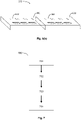
- the firmware 302(d) may incorporate a self-starting algorithm for determining whether the sensing device can automatically start data recording. With reference to Figure 7 , the self-starting algorithm 700 may perform for example the following four steps.
- the sensing device 201 may be operated in an idle mode in which the processor unit 302 may command the sensor unit 201 to sample the bloodstream of the wearer once every e.g., 20 seconds for a duration of e.g., 3 seconds. If a heartbeat signal having an amplitude greater than a predefined threshold and features matching a predefined heart waveform is detected, the algorithm may proceed to step 702. Otherwise, the algorithm may stay at step 701.
- the processor unit 302 may check if the detected heartbeat signal having an amplitude greater than the predefined threshold and features matching the predefined heart waveform. Wearer heart rate may be compensated for by expanding and contracting the predefined heart waveform until a match with the measured heart activity is established. This may prevent noise from triggering automatic recording. If the heartbeat signal successfully matches the predefined criteria, the algorithm may then proceed to step 703. Otherwise, the algorithm may return to step 701.
- the processor unit 302 may further check if the heartbeat signal acquired during the 3-second sampling window matches substantially to a predefined heartbeat signal stored in the on-board memory 303(c), the algorithm may proceed to step 704. Otherwise, the algorithm may return to step 701.
- the processor unit 302 may allow the densely sampled raw data to be processed and encrypted before being committed to the on-board memory 303(c). Data recording will continue unless the amplitude of the heartbeat signal drops below the predefined threshold, in which case, the algorithm will repeat steps 701 to 703 until a new recording session is established.
- the computing device 203 may be a general purpose computer that is connected to the internet via an Ethernet cable.
- the computing device 203 may be connected to the charging device 202 via a USB cable to allow data transfer from the sensing device 201.
- a dedicated software application may be installed on the computing device 203 which enables the communication between the computing device 203 and the online analysis platform 204.
- the online analysis platform may be accessed by a web browser installed on the computer device 203.
- the data received from the sensing device 201 may be temporally stored in a folder created for containing the data from this particular device.
- the data stored in the sensing device 201 may be directly uploaded to the online analysis platform via the dedicated software application or the web browser without being stored in the computing device. In this way, privacy protection of the system may be enhanced.
- the online analysis platform 204 may be a cloud based data hub which allows for development and implementation of various cloud-based algorithms.
- the online analysis platform 204 may further comprise a data processing function block 801, a data analysis function block 802 and a database 803.
- the data processing function block 801 may comprise one or more data processing algorithms employed to decrypt the data, further process the data and generate a high fidelity heart rhythm waveform.
- the data analysis function block 802 may comprise one or more data analysis algorithms configured to perform deterministic analysis on the heart rhythm waveform and identify features that are capable of indicating any heart rhythm abnormalities.
- the data analysis function block 802 may also generate an analysis report based on findings of the analysis.
- the database 803 may be used to contain the high fidelity heart rhythm waveforms and the analysis report.
- the data processing function block 801 may decrypt the data by means of a decryption key.
- the decryption key may be sensing device specific and thus can only be used to decrypt data from a particular sensing device.
- the decrypted data may be further processed by the data processing function block 801.
- the data processing may comprise data smoothing by means of e.g., Savitzky-Golay smoothing and/or moving average.
- Savitzky-Golay smoothing is a low-pass filtering technique which attenuates higher frequency noise while suppressing low-frequency noise derived from wearer motion. This is a Finite Impulse Response (FIR) filter meaning its impulse response is of finite duration.
- FIR Finite Impulse Response
- the data processing may further comprise subtracting the data originated from the accelerometer 301(b) from the data originated from the multi-channel pulse oximeter 301(a) so as to remove or minimise the motion induced data interference.
- the data processing function block 801 may perform recompiling of pulsatile coordinate data points so as to generate a corresponding full heart rhythm waveform, similar to the waveform shown in Figure 1 .
- the generated high fidelity heart rhythm waveform may then be stored in a directory created in the data base 803 that is dedicated for storing the information of the wearer.
- the deterministic analysis performed by the data analysis function block 802 may comprise three main steps: step 901, identifying features indicative of heart rhythm anomalies on the generated heart rhythm waveform; step 902, assigning evidence scores to the identified features; step 903, calculating an overall evidence score based on the previously assigned evidence scores; step 904, determining presence of heart arrhythmia based on the overall evidence score.
- the deterministic analysis may be carried out in a way described below.
- the high fidelity heart rhythm waveform may be used for computation of systolic peak (R-wave 130 analogue), calculation of peak-to-peak intervals, interpolation of peak-to-peak times over a number of measured heart cycles to establish variance, and computational identification of the presence of features which may be indicative of a P-wave.
- the computation of systolic peak may be achieved via e.g., calculation of the positive-to-negative slope change on signals with an amplitude >75% of the maxima of all measured samples to that point (repeats for each waveform).
- the calculation of peak-to-peak intervals may be achieved via e.g., subtraction of the time measurements between the most recently identified R-wave-equivalent 130 peak and the previously measured peak.
- the variance may be compared to an established acceptable range in order to identify anomalous variance.
- the computational identification of the presence of features may be achieved via e.g., negative-to-positive and positive-to-negative slope calculations on a set number of data points preceding identified systolic peaks;
- flaggable anomalies of the heart rhythm waveform may be determined and an AFib evidence score may be assigned to each of them.
- the flaggable anomalies may comprise for example absence of features which may be indicative of a P-wave-equivalent 110, and R-wave-equivalent 130 variation outside of a predefined nominal range.
- the flagged data may be further processed for false-positive reduction.
- This may be achieved via e.g., analysis of flagged areas via derivative threshold algorithm analysed by a machine learning (ML) model such as support vector machine model (SVM).
- An SVM is a supervised learning model designed to be utilised with learning algorithms which examine data for classification and regression analysis, resulting in waveform features being detected with greater reliability.
- Analytical methods within this ML algorithm may comprise for example time-frequency examination, singular value decomposition, empirical mode decomposition, sparse signal recovery, and spectrum analysis for spectral-peak tracking. These methods may aid in obtaining usable data in the case that motion-induced interference is still present.
- the ML algorithm is essentially searching for sequences of P-P irregularity and patterns which indicate the presence of features which may represent a P-wave-equivalent 110, both of which are deduced as present or absent via the calculation of evidence scores.
- the strength of these evidence scores stems from data training sets that the ML algorithm has learned from.
- the post-processing flagged data may then be used for recalculation of AFib evidence scores and further training of the ML model.
- the final AFib evidence scores may be used to determine the presence of AFib and the relevant analysis data may be used for compiling of a final report.
- the report may be for example in PDF format in which a red box may be drawn around the sectioned anomalous waveforms, and a timestamped notification, link, and explanation for the flagged anomaly may be shown.
- the system of Figure 2 may be used to provide an end-to-end service for patient screening for AFib and other heart rhythm abnormalities.
- the end-to-end service may comprise for example the following three phases.
- the clinician opens a browser-based referral portal (or the online analysis platform 204) and enters the patient's details.
- a patient directory is automatically created in the online portal upon clinician referral.
- the supplier or distributor of the sensing devices is notified of the referral, which is accepted by selecting the newly created directory and clicking 'link device'.
- the online portal detects a technician removing a sensing 201 device up from a charging device 202, pairing the patient directory with that specific sensing device 201 automatically (in a similar fashion to how a computer detects the removal of a USB device).
- a decryption key is generated upon the directory association, used to decrypt data uploaded at the end of the collection period.
- the sensing device 201 is placed in a package along with other accessories, such as body attachment means (e.g. straps, bands (wristbands/armbands)) and user manual.
- the patient Upon receiving the sensing device 201, the patient attaches the sensing device 201 to their body (e.g. puts the wristband on his/her wrist).
- the sensing device 201 can be worn continuously for the duration of monitoring (up to 90 days).
- the sensing device 201 automatically begins data recording after a satisfactory heartbeat signal is detected. By the time a prescribed monitoring period has passed, the patient returns the sensing device 201 to the supplier.
- the technician Upon receiving the sensing device 202, the technician places the sensing device 201 into a charge device 202 and enables data uploading to the online portal.
- the uploaded data is decrypted with the unique decryption key and subsequently processed in a desired manner.
- An analysis report is generated after a deterministic analysis, e.g., the analysis process shown in Figure 10, is performed on the processed data.
- the analysis report containing the information as to whether or not heart rhythm abnormalities are present is sent to the clinician for review.
- any person may be able to buy a sensing device 201 along with a charging device 202 and other accessories (e.g., a wristband and a manual) from a local store or an online store.
- the person may register a user account on the online analysis platform 204 and create a personal profile by providing relevant personal information.
- the person may wear the sensing device and start recording his/her heart rhythm data. After a recommended recording period is over or the battery is discharged (e.g., 90 days), the sensing device 201 may be placed into the charging device 202 which is connected to a personal computer 203.
- the physical connection between the sensing device 201 and the charging device 202 may enable charging of the sensing device 201 as well as uploading the recorded data to the online analysis platform 204 either via a dedicated software application or a web browser.
- the online analysis platform 204 may perform deterministic analysis as shown in Figure 9 and may provide the person with an evaluation result as to whether or not heart rhythm abnormalities (e.g., AFib) are detected during the last recording period. Relevant heart rhythm data may also be shown in order to support the finding/evaluation.
- the person may then send the evaluation result and the supporting data to a medical doctor (e.g., general practitioner (GP)) who will decide if a referral for specialist treatment is needed, for example.
- GP general practitioner
Abstract
A wearable device for long-term, continuous heart rhythm monitoring during everyday activity, comprising a sensor unit comprising at least one pulse oximeter; a processor unit; a memory unit; a power unit comprising a battery; wherein, the at least one pulse oximeter is configured to measure optically a bloodstream at a sampling rate and output measured data; wherein, the processor unit is configured to process the measured data and determine a time for the processed data to be automatically recorded in the memory unit; wherein, the processor unit is configured to dynamically adjust the sampling rate of the at least one pulse oximeter by based on a predetermined event.
Description
- The present invention relates to methods and systems for long-term monitoring of heart rhythm and the detection of heart rhythm abnormalities, in particular for reliable and accurate detection of intermittent/asymptomatic atrial fibrillation.
- Atrial fibrillation (AFib) is the most common heart rhythm irregularity, affecting over 33.5 million individuals globally, and is the source of significant preventable annual healthcare costs worldwide. The pathology causes a decrease in the efficiency of the heart's ability to pump blood, potentially resulting in clot formation. AFib is responsible for 50% of all fatal ischemic strokes, and sufferers are at a 5 times higher risk of stroke. Silent AFib constitutes up to 60% of all AFib and greatly extends the time to diagnosis due to the intermittent and asymptomatic nature of the AFib events. Early detection of this form of AFib presents challenges in the form of continuous recording duration, which are hampered by monitoring device convenience, type, environment of use, and wearer-compliance.
- The current gold standard approach for monitoring and recording heart waveforms non-invasively is electrocardiography (ECG). ECG records the electrical activity of the heart and stores the waveform, which is typically printed out to a screen / document. Wearable ECG monitors are not an ideal solution for monitoring periods which span more than a small number of days, and it is unable to record the heart waveform reliably during excessive motion, or while wet. In addition, ECG monitors tend to be large, inconvenient, and power hungry.
- Pulse oximetry is an alternative approach to measuring heart activity, but its utility has thus far been limited to measuring pulse rate and blood oxygenation levels rather than full heart rhythm. Pulse oximetry operates by sampling the bloodstream with light pulses and measuring property changes (e.g., intensity) of light pulses passing through or reflecting from the bloodstream. For example, by measuring intensity changes of light with varying wavelengths, the haemoglobin/deoxyhaemoglobin gradient change representing blood volume in a vessel at any given point in time can be monitored/measured. This data can provide in-depth information on cardiovascular functionality with the application of advanced processing methods.
- Pulse oximeter sensors are featured in many sports wearables such as sports trackers or smartwatches today. These platforms typically offer a host of other features such as GPS, fitness applications, Bluetooth, Wi-Fi, screen display and more in order to compete within the consumer market. The pulse oximeter sensors incorporated into these devices are low performance, and are incapable of providing the data that cardiologists need in order to detect waveform abnormalities which may be indicative of AFib. For example, existing pulse oximetry-based devices typically have a low sampling/polling frequency in the range of 5 Hz to 215 Hz. A poor temporal resolution, resulting from a low sampling frequency, makes such devices unable to resolve certain temporal features of a heart rhythm waveform that are important for determining AFib. As such, the output waveform readings from such devices are of lower quality and lower reliability. In addition to this, the necessity of hosting a wide range of functionality to maintain a competitive edge within the consumer market limits battery life, curtailing a key feature necessary to reliably monitor for infrequently occurring heart rhythm abnormalities over long durations.
- Due to specific difficulties in identifying silent AFib, patients can wait years to obtain a diagnosis using current wearable heart rhythm monitoring methods such as Holter monitor and patch ECGs, leaving sufferers at significant risk of stroke, and leaving health systems exposed to significant cost increases. The intermittent nature of silent AFib means that it is difficult to detect accurately and reliably without a system which can monitor continuously in everyday settings for time periods extending into weeks and months.
- Hence, it is the objective of this disclosure to provide a method and a system that are based on pulse oximetry and are dedicated for long-term continuous heart rhythm monitoring. The proposed method and system are capable of reliably detecting heart rhythm abnormalities e.g., heart arrhythmia while obviating or mitigating most or all of the aforementioned problems associated with existing monitoring devices.
- In accordance with a first aspect of the present invention, there is provided a wearable device for heart rhythm monitoring, comprising a sensor unit comprising at least one pulse oximeter; a processor unit; a memory unit; a power unit comprising a battery; wherein, the at least one pulse oximeter is configured to measure optically a bloodstream at a sampling rate and output measured data; wherein, the processor unit is configured to process the measured data and determine a time for the processed data to be automatically recorded in the memory unit; wherein, the processor unit is configured to dynamically adjust the sampling rate of the at least one pulse oximeter based on a predetermined event.
- In accordance with a second aspect of the present invention, there is provided a charging device configured for charging and transferring data from a wearable device according to the first aspect, comprising: an AC-DC Converter configured to convert the mains AC supply to DC power; a data transfer and charging unit comprising a data transfer and charging circuitry; and at least one charging bay recessed from a top surface of the charging device and configured to accommodate the wearable device; wherein, the at least one charging bay comprises one or more metal contact points configured to establish complementary connections to the wearable device, further wherein each metal contact point is connected to one contact of the data transfer and charging circuitry.
- In accordance with a third aspect of the present invention, there is provided a system for detecting heart rhythm abnormalities, comprising a wearable device according to the first aspect of the present invention, a charging device as according to the second aspect of the present invention, a computing device in connection with both the charging device and the internet; and an online analysis platform accessible by the computer device and configured to process and analyse electrical data transferred from the wearable device in order to determine heart rhythm abnormalities; wherein upon detecting a satisfactory heartbeat signal, the wearable device automatically begins recording of electrical signal data obtained by optically measuring a bloodstream at a sampling rate; wherein the wearable device is operable to dynamically adjust the sampling rate based on a predetermined event.
- In accordance with a fourth aspect of the present invention, there is provided a method for heart rhythm monitoring, comprising: measuring optically a bloodstream optically at a sampling rate and outputting measured data using at least one pulse oximeter; processing the measured data and determining a time for the processed data to be automatically recorded using a processor unit; adjusting dynamically the sampling rate of the at least one pulse oximeter based on a predetermined event.
- Embodiments of the present invention will now be described by way of example only and with reference to the accompanying drawings, in which:
-
Figure 1 depicts features of an example heart rhythm waveform; -
Figure 2 depicts a block diagram of a system for detecting a heart rhythm abnormality in accordance with an embodiment; -
Figure 3 depicts a block diagram of the heart rhythm monitoring device used in the system for detecting heart arrhythmia in accordance with an embodiment; -
Figure 4 depicts a perspective view of the heart rhythm monitoring device in accordance with an embodiment; -
Figure 5 depicts a block diagram of the charging device used in the system for detecting heart arrhythmia in accordance with an embodiment; -
Figure 6 depicts a perspective view of the charging device in accordance with an embodiment; -
Figure 6a depicts a perspective view of two charging devices arranged in a stacking manner in accordance with an embodiment; -
Figure 6b depicts a perspective view of two charging devices that are connected horizontally in accordance with an embodiment; -
Figure 7 depicts a flowchart of the self-starting algorithm employed by the heart rhythm monitoring device to enable automatic data recording in accordance with an embodiment; -
Figure 8 depicts a block diagram of the online analysis platform in accordance with an embodiment; and -
Figure 9 depicts a flowchart of deterministic analysis performed by the data analysis function block of the online analysis platform in accordance with an embodiment. - With reference to
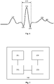
Figure 1 , there is illustrated an example electrocardiogram of a single heartbeat. The electrocardiogram is a tracing of the electrical activity taking place within a heart. Under normal circumstances, an electrical impulse travels from the sinoatrial node, across the atrium and to the atrioventricular node and through the ventricular septum of the heart. Excited by the electrical impulse, the four chambers of the heart contract and relax in a coordinated manner. As illustrated inFigure 1 , the example electrocardiogram of a single heartbeat comprises multiple peaks and troughs representing different stages of heart beating. The peaks and troughs are denoted from the left to right as P-wave 110, Q-wave 120, R-wave 130, S-wave 140, T-wave 150 andU-wave 160, among which the P-wave 110 and the R-wave 130 are the most important features for detecting heart arrhythmia. - The P-
wave 110 represents the atrial contraction and indicates the atrial depolarization. The Q-wave 120, R-wave 130 and S-wave 140 are named asQRS complex 170 which represents the electrical impulse as it spreads through the ventricles and indicates ventricular depolarization. TheQRS complex 170 starts just before ventricular contraction. The T-wave 150 following theQRS complex 170 indicates ventricular repolarization. Heartbeat regularity is established by measuring time intervals between any two successive R-wave 130 peaks. Fibrillation of the atria is indicated by the absence of the P-wave 110. Measurement of irregular contractions of the atria and monitoring heart rate relative to the activity level of a patient are both important for identification of AFib. Note that not all pulsatile features indicative of some smaller waveform features displayed inFigure 1 are easily measurable using pulse oximetry. For example, pulsatile characteristics representing the action driving the Q-wave 120, S-wave 140, T-wave 150, and U-wave 160 present detection challenges due to not resulting in large heart contractions which are detectable via haemoglobin level differences in the bloodstream, or occur before ventricular contractions push blood out of the heart. However, these waveform features are not critical for the detection of AFib. - Typically, a silent AFib patient will not physically feel any symptoms, and will not know they are at a significant risk of stroke. Hence, identification of AFib relies on a system which can be used over a prolonged period of time during everyday activities. As ECG is not suitable for everyday use, the invention seeks to provide everyday and prolonged monitoring using a pulse oximetry-based system which can accurately and reliably capture those critical indicative features, e.g., P-wave and R-wave-equivalents. As mentioned above, the sampling frequency of existing pulse oximetry based devices typically lies in the range of 5 Hz and 215 Hz. A low sampling rate (and thus low temporal resolution) will only allow pulse oximeters to measure a parameter called the 'first derivative photoplethysmogram', which gathers information on blood oxygenation levels by measuring blood flow through large vessels. By contrast, detecting volume changes in small vessels (capillaries) using a high sampling rate (and thus high temporal resolution) will allow pulse oximeters to measure a parameter called the 'second derivative photoplethysmogram' (SDPPG), which can provide insights into the functionality of the heart chambers. In order to meet the demand of high temporal resolution, a pulse oximetry based monitoring device that is capable of providing a sampling rate of over 215 Hz, and preferably over 500 Hz, is highly desired. A pulse oximetry-based heart arrhythmia-detecting system capable of providing sufficiently high sampling frequency coupled with advanced filtering and noise-reduction algorithms is able to produce a high quality heart rhythm waveform analogous in clinical usefulness to that produced by ECG for the purposes of heart arrhythmia identification, and meanwhile enables extended and continuous recording durations due to the comparatively lower power requirements of pulse oximeter sensors and the devices usability in everyday settings.
- With reference to
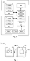
Figure 2 , there is illustrated a block diagram of the heartarrhythmia detecting system 200 in accordance with an embodiment. The block diagram shows the core components of the system and the relationship between them. In some embodiments, the system may comprise a wearable heart rhythm monitoring device (or sensing device) 201, acharging device 202, acomputing device 203, and anonline analysis platform 204. In some embodiments, the chargingdevice 202 may incorporate all the functions of thecomputing device 203 and thus a separate computing device will not be needed. In other embodiments, the heartarrhythmia detecting system 200 may comprise one or more other functional components that are not illustrated in the block diagram ofFigure 2 . Thesensing device 201 may be configured to collect data from the bloodstream of a person, e.g., a patient, which can be used later to derive a high fidelity heart rhythm waveform. The chargingdevice 202 in connection with thecomputing device 203 may be configured to charge thesensing device 201 and enable data transfer from thesensing device 201 to thecomputing device 203. Thecomputing device 203 in connection with the internet, may be configured to receive the data from thesensing device 201, and subsequently or simultaneously upload the data to theonline analysis platform 204. Theonline analysis platform 204 may be configured to further process the data, analyse the processed data and finally generate an evaluation report. - Each of above-mentioned core components will be described in detail below. With reference to
Figure 3 , there is illustrated a block diagram of the functional components of the sensing device and their interactions in accordance with an embodiment. In the embodiment, thesensing device 300 comprises asensor unit 301, aprocessor unit 302, amemory unit 303, apower unit 304, and aninterface unit 305. - In some embodiments, the
sensor unit 301 may comprise at least one multi-channel pulse oximeter 301(a), at least one tri-axis accelerometer 301(b) and at least one internal temperature sensor 301 (c). The multi-channel pulse oximeter 301 (a) may comprise a light emitter emitting at least two optical wavelengths. In some embodiments, the multi-channel pulse oximeter 301(a) may emit wavelengths in blue, green, yellow, red, and infrared wavelengths between 400 and 970nm, cycling between them periodically dependent on activity levels, and as charge levels vary. In other embodiments, the multi-channel pulse oximeter 301(a) may only emit two wavelengths, i.e. 660 nm and 940 nm, sequentially and periodically. The sampling frequency of the multi-channel pulse oximeter may be controlled by theprocessor unit 302. The multi-channel pulse oximeter 301(a) may be operable at a high sampling rate. In some embodiments, the sampling rate may be preferable to be greater than 215 Hz. In other embodiments, the sampling rate may be preferable to be greater than 500 Hz. In different embodiments, the sampling rate may be adjustable for example, between 5 Hz and 1000 Hz, between 215 Hz and 500, between 215 Hz and 800 Hz, or between 215 Hz and 1000 Hz. - In some embodiments, the
sensor unit 301 may further comprise a tri-axis accelerometer 301 (b). The tri-axis accelerometer may be used to track motion of a wearer. Every time the pulse oximeter 301 (a) is sampled, so is the accelerometer 301 (b) such that there are corresponding data points for every logged sample. The pulse oximeter 301 (a) picks up signals caused by motion, and signals derived from blood volume changes within vessels. The accelerometer 301 (b) picks up signals caused by motion alone. Subtracting one from the other leaves signals due to blood volume changes. Within the device, signals from both the pulse oximeter 301 (a) and accelerometer 301 (b) are committed to memory, with processing done later via algorithms hosted on theonline analysis platform 204. - In some embodiments, the
sensor unit 301 may further comprise an internal temperature sensor 301(c). The internal temperature sensor 301(c) ensures that thesensing device 301 is running at a safe temperature. In addition to its standard use as a safety feature (whereby devices are powered down should they exceed a certain temperature threshold), the temperature data may be used to further refine system architecture over time by analysing trends in device temperature changes over time. Temperature data may be logged at regular intervals to infer additional information about patient activity. - In some embodiments, the
sensor unit 301 may further comprise one or more circuits for noise reduction and/or signal amplification. The noise reduction circuit may comprise a low pass filter configured to remove motion induced low frequency noise on the sensor signal. The signal amplification circuit may allow the sensor signal to be amplified to a certain level required by theprocessor unit 302. - In some embodiments, the
processor unit 302 may further comprise an arithmetic logic unit 302(a), a control unit 302(b), register arrays 302(c) and firmware 302(d). The arithmetic logic unit 302(a) performs arithmetic and logic operations guided by the control unit 302(b) on data from the input registers. The corresponding result is stored on an output register. The control unit 302(b) directs the operations of theprocess unit 302. It controls the logic behind arithmetic logic unit 302(a), the register arrays 302(c) and input and output devices on how to respond to the firmware instructions. Registers 302(c) are small amounts of storage within theprocessor unit 302. Input registers store data from the external sensors, e.g., sensors in thesensor unit 301, the control unit 302(b) guides the arithmetic logic unit 302(a) on what operations to perform on the data based on the firmware instructions and the corresponding results from the arithmetic logic unit 302(a) are stored in output registers for transfer back to the external sensors. The system firmware 302(d) controls the functionality of each of e.g., the inputs, storage, and power management on board the device. - In some embodiments, the
memory unit 303 may further comprise a real-time clock 303(a), a random access memory 303(b) and an on board memory 303(c). The real-time clock 303(a) keeps track of the time. Theprocessor unit 302 may read this time and append a timestamp to every data log committed to the device's internal memory. The real-time clock 303(a) may be refreshed every time thesensing device 201 is returned to a charging station in order to compensate for time-slips (RTC's are highly accurate, but not perfect and need to be refreshed periodically). The random access memory 303(b) may be used to temporally store the sampled data before it being arranged appropriately, encrypted by theprocessor unit 302, and eventually committed to long-term on board memory 303(c). The on board memory 303(c) may be in the form of flash storage designed to hold the gathered, encrypted data. This memory 303(c) may be wiped after successful confirmation of data uploading to the online portal. The write-rate of the on board memory may be tailored to match the unusually high throughput demands caused by multiple streams of high-fidelity data. - In some embodiments, the
power unit 304 may further comprise a power management integrated circuit 304(a), a battery charger 304(b), and a battery 304(c). The power management integrated circuit 304(a) disseminates power amongst the various electronic components. Theprocessor unit 302, receiving information from thesensor unit 301, can influence the functionality of the power management integrated circuit 304(a) as the sampling rates are controlled by applying varying power levels to the sensors of thesensor unit 301, which in turn impacts battery longevity. The battery charger may be capable of receiving power from the chargingdevice 202 and enabling fast-charging of the device's battery 304(c). The battery 304(c) itself may possess a large charge capacity in order to satisfy the need of long term continuous heart rhythm monitoring. The large charge capacity (hence a large battery size) is enabled by the large internal volume of thesensing device 201 after many superfluous features that are typically adopted in existing wearable heart rate monitors are removed. In some embodiments, the battery 304(c) may have a charge capacity in the range between 1000 milliamp-hour (mAh) and 3000 mAh. In other embodiments, the charge capacity may be in the range between 1200 mAh to 2200 mAh. - In some embodiments, the
power unit 304 may further comprise a low dropout regulator which may act to maintain a constant voltage to theprocessor unit 302 and thesensor unit 301 regardless of the level of charge of the battery (for example, at full charge, the battery may be running at 4.2 V, and when near fully discharged the battery may be running at 2.7 V. The low dropout regulator maintains a constant 2.5 V regardless of this); a DC-DC converter may work in parallel to the low dropout regulator to convert a source of one DC voltage level to another level; and a smart reset which may only allow current to flow once the voltage reaches e.g., 2.5 V from the battery. When this has been reached, the PMIC is reset and the low dropout regulator maintains a constant 2.5V. - In some embodiments, the
interface unit 305 may enable connections between thesensing device 201 and the outside world for the purposes of e.g., human interaction, data transfer and power charging.Figure 4 shows a perspective view of thesensing device 201 according to an embodiment. As shown inFigure 4 , thesensing device 201 may comprise anexternal casing 401 which encloses all the electrical components ofsensing device 201 and is in direct contact with the wearer's body. When placed on the wrist, theexternal casing 401 may comprise fixing features allowing theexternal casing 401 to be connected to a wrist band or strap. In other embodiments, thesensing device 201 may be placed on the arm and may be facilitated by connecting theexternal casing 401 to an arm band or strap. Note that, thesensing device 201 may also be used on other different parts of the body. - In some embodiments, the
external casing 401 may comprise abutton 402, multiple indication light emitting diodes (LEDs) 403 and anoptical window 404. In some embodiments, theinterface unit 305 may be configured to connect theprocessor unit 302 to thebutton 402 andindication LEDs 403. In some embodiments, thebutton 402 may be a mechanical and capacitive button and may be located on the peripheral area of theexternal casing 401 of thesensing device 201. Clicking thebutton 402 may add a timestamp to the data being recorded at that time, which may draw extra attention to that area when the data is reviewed. Touching thebutton 402 may cause the battery levels to display viaindication LEDs 403 on the front face of the external casing for a short period of time. In some embodiments, theindication LEDs 403 may comprise for example four RGB LEDs. Each LED may represent 25% of battery remaining. All LED's displaying a constant yellow may mean the device is in 'programming mode' (for firmware updates). All LED's displaying a constant blue may mean the device is in 'docked mode'. All LED's flashing blue may mean the device is transferring data. All LED's flashing orange may mean the device is in 'detection mode' (e.g., the device is being paired with a newly created patient directory). In some embodiments, theoptical window 404 may be located directly underneath the pulse oximeter 301(a) and may be transparent to all the wavelengths of the pulse oximeter 301(a). - In some embodiments, part or all of the
external casing 401 may be made of a polyurethane gel elastomer with a low refractive index. In different embodiments, only the bottom part of theexternal casing 401 which is in direct contact with the skin may be made of a polyurethane gel elastomer. This is expected to decrease motion induced interference caused by wearer activity via more effective impact absorption (or 'shake compensation') without compromising sensor readings that may be caused by the presence of an additional medium for the pulse oximeter light to travel through. Existing wearable devices use a fluoroelastomer to stabilise the sensor against the skin. The polyurethane gel elastomer possesses a higher friction coefficient than fluoroelastomers, providing enhanced stability through additional grip. In some embodiments, theexternal casing 401 may have a curved body shape designed to follow for example the wrist curvature. In this way, the stability of sensor connections can be further improved. In some embodiments, thesensing device 201 may adopt a contact point configuration where each contact of a data transfer and charging circuitry is internally rerouted to one metal contact point arranged on theexternal casing 401. The data transfer and charging circuitry may comprise for example a 4-pin USB circuitry. - With reference to
Figure 5 , the charging device may possess data transfer and charging connection points complementary to the sensing device. The chargingdevice 202 may comprise an AC-DC Converter 501 which converts the mains AC supply to DC power usable by the chargingdevice 502, and a data transfer and chargingcircuitry unit 502 which is complementary to the contact points of thesensing device 201. The chargingdevice 202 may be configured to comprise internally rerouted data transfer and charging connectors to receive and make contact with the metal contact points on thesensing device 201. When the two devices are in physical contact with each other, each of the metal contact points on thesensing device 201 connects to the corresponding metal contact point on thecharging device 202 and thus a connection is established. A number of the metal contact points may be used for data transfer between the on board memory 303(c) and thecomputing device 203. The other metal contact points may be used for charging. The complementary data transfer and charging connections between thesensing device 201 and thecharging device 202 may be based on protocols such as for example USB 3.0, USB-C, or RS232. - With reference to
Figure 6 , in some embodiments, the chargingdevice 202 may comprise a plurality of charging bays, each being configured to accommodate a single sensing device. Each charging bay may correspond to a cavity recessed from the top surface of the body of thecharging device 202. The dimensions of the recessed cavity may be slightly larger than those of thesensing device 201. The secure seating and connection may be achieved via the use of one or more magnets located in both the device body and charging bay. The contact points on each side allow for broad lateral expandability so that a mesh of charging bays can be created horizontally whilst minimising the number of necessary cables to two (e.g., one power cable and one USB cable). Depending on application, each chargingdevice 202 may comprise 5, or 10, or 15, or 20, or 30 charging bays. With reference toFigure 6(a) , in some embodiments, two or moreindividual charging devices 202 may be stacked vertically to form a composite charging device 202' and can work in parallel by sharing the same electrical supply. Two chargingdevices 202 may be connected vertically using mechanical means, e.g., fourposts 603. Alternatively, or additionally, two or moreindividual charging devices 202 may be connected horizontally to form acomposite charging device 202" (as shown inFigure 6(b) ), thereby further increasing expandability of thecharging device 202. Two chargingdevices 202 may be connected horizontally using mechanical means, e.g., two dowel joints (not shown), or magnetically. - In order to obtain high fidelity waveforms that are capable of revealing certain fine features in relation to heart rhythm abnormalities, such as for example the absence of the p-
wave 110, the multi-channel pulse oximeter 301(a) and accelerometer 301(b) may preferably have a sampling rate between 215 Hz and 1000 Hz. In some embodiments, the sampling rate may be dynamically adjusted in the range between 215 Hz and 1000 Hz by the processor unit 302 (as controlled by the system firmware 302(d)) in response to a predetermined event. The predetermined event may be for example an increased physical activity, a change in signal quality, or a decreased battery level. For example, data measured by the accelerometer 301(b) may be used to at least partially determine the sampling rate through detecting increased activity levels, which theprocessor unit 302 responds to by increasing the sampling rate of both the accelerometer and pulse oximeter. In such a manner, small features which are easily disguised by motion-induced interference can be recovered more readily by processing algorithms used later in theonline analysis platform 204. Moreover, when quality of one or more sensor signals vary, the sampling rate may be also dynamically adjusted by theprocessor unit 302. For example, when the quality of the pulse oximeter signal degrades, theprocessor unit 302 may increase the sampling rate of both the accelerometer and pulse oximeter in order to substantially maintain a good data fidelity. - In parallel, a power-saving strategy may be employed which allows the
sensing device 201 to decrease the rate of active sampling (e.g., from an initial rate of 1000 Hz to a later rate of 500 Hz) as battery-life decreases. The sampling rate may be reduced in a step-by-step manner and may be adjusted periodically. In some embodiments, theprocessor unit 302 may periodically check the remaining charge level of the battery 304(c) and calculate a percentage drop in the charge level over the last period of time. Then, theprocessor unit 302 may adjust/reduce the sampling rate by an amount proportional to the percentage change of the charge level of the battery 304(c). Fine control of the dynamic sampling rate contributes significantly to both the longevity of battery and the fidelity of the data. With the help of the dynamic sampling control and a large capacity battery, thesensing device 201 is able to provide a single continuous recording period of up to 90 days, or approximately 90 days, or greater than 90 days, thereby significantly increasing the detection rate of heart rhythm abnormalities, such as AFib. - In some embodiments, the
processor unit 302, or more specifically the firmware 302(d), may be configured to maintain a virtually constant sampling rate when the sampling rate decreases as a result of the decrease of the battery charge or the increase of the wearer's physical activity. The virtually constant sampling rate may be maintained by applying interpolation to the data obtained with a decreasing sampling rate. Interpolation offers the ability to reduce the live sampling rate gradually over time, as battery life decreases, whilst preserving accuracy of the waveform. The extent to which interpolation is used will vary depending on battery performance. It may be used from the beginning to end of recording duration if necessary, as battery degradation occurs over time with repeat uses of the same device. For example, when the sampling rate has reduced from e.g., initial 1000 Hz to current 500 Hz as a result of discharging of the battery 304(c), the number of measured data points per second dropped correspondingly from 1000 to 500. - As mentioned above, insufficient sampling results in poor temporal resolution and therefore low fidelity heart rhythm waveform. Hence, to compensate for such data point loss, interpolation density is increased accordingly such that the total number of data points (measured and interpolated) per second is maintained to be 1000, corresponding to a constant sampling rate of 1000 Hz. Interpolation may be performed on the measured data by the
sensing device 201 while the data is being recorded. Alternatively, it may be performed on data post-collection in order to reduce signal noise attributable to physical motion and other environmental factors. This processing may be performed on thedata analysis platform 204 and may be supplemental to the electrical filtering performed on-board the device. In some embodiments, different interpolation methods may be applied to different parts of the measured data. For example, in the case where the measured sensor signal changes linearly with time, linear interpolation will be applied. In the case where the measured sensor signal changes nonlinearly with time, polynomial interpolation will be selected. The application of interpolation allows the sensor unit (e.g., the multi-channel pulse oximeter) to be operated at low sampling rates (e.g., between 5 Hz and 215 Hz) while simultaneously maintaining a sufficient number of data points and therefore ensuring a high fidelity heart rhythm waveform. - In some embodiments, the firmware 302(d) may format the data appropriately, perform encryption, and log the encrypted data to the on-board memory 303(c) live. In some embodiments, data formatting may comprise further software-based filtering and smoothing (e.g., Savitzky-Golay smoothing). Data encryption may be obtained by means of e.g., a cryptographic algorithm (algebraic matrix-based).
- In some embodiments, the
sensing device 201 may immediately begin detecting a heartbeat signal when placed on a part of a wearer's body. As soon as the heartbeat signal is detected and simultaneously meets one or more predefined conditions, thesensing device 201 may automatically begin recording of the data which may had been filtered, formatted and encrypted by the hardware as well as firmware of thesensing device 201. The firmware 302(d) may incorporate a self-starting algorithm for determining whether the sensing device can automatically start data recording. With reference toFigure 7 , the self-startingalgorithm 700 may perform for example the following four steps. - At
step 701, when not being worn, thesensing device 201 may be operated in an idle mode in which theprocessor unit 302 may command thesensor unit 201 to sample the bloodstream of the wearer once every e.g., 20 seconds for a duration of e.g., 3 seconds. If a heartbeat signal having an amplitude greater than a predefined threshold and features matching a predefined heart waveform is detected, the algorithm may proceed to step 702. Otherwise, the algorithm may stay atstep 701. - At
step 702, theprocessor unit 302 may check if the detected heartbeat signal having an amplitude greater than the predefined threshold and features matching the predefined heart waveform. Wearer heart rate may be compensated for by expanding and contracting the predefined heart waveform until a match with the measured heart activity is established. This may prevent noise from triggering automatic recording. If the heartbeat signal successfully matches the predefined criteria, the algorithm may then proceed to step 703. Otherwise, the algorithm may return to step 701. - At
step 703, theprocessor unit 302 may further check if the heartbeat signal acquired during the 3-second sampling window matches substantially to a predefined heartbeat signal stored in the on-board memory 303(c), the algorithm may proceed to step 704. Otherwise, the algorithm may return to step 701. - At
step 704, theprocessor unit 302 may allow the densely sampled raw data to be processed and encrypted before being committed to the on-board memory 303(c). Data recording will continue unless the amplitude of the heartbeat signal drops below the predefined threshold, in which case, the algorithm will repeatsteps 701 to 703 until a new recording session is established. - With reference to
Figure 2 , in some embodiments, thecomputing device 203 may be a general purpose computer that is connected to the internet via an Ethernet cable. Thecomputing device 203 may be connected to thecharging device 202 via a USB cable to allow data transfer from thesensing device 201. In some embodiments, a dedicated software application may be installed on thecomputing device 203 which enables the communication between thecomputing device 203 and theonline analysis platform 204. In other embodiments, the online analysis platform may be accessed by a web browser installed on thecomputer device 203. In some embodiments, the data received from thesensing device 201 may be temporally stored in a folder created for containing the data from this particular device. In other embodiments, the data stored in thesensing device 201 may be directly uploaded to the online analysis platform via the dedicated software application or the web browser without being stored in the computing device. In this way, privacy protection of the system may be enhanced. - With continued reference to
Figure 2 , theonline analysis platform 204 may be a cloud based data hub which allows for development and implementation of various cloud-based algorithms. In some embodiments, theonline analysis platform 204 may further comprise a dataprocessing function block 801, a dataanalysis function block 802 and adatabase 803. The dataprocessing function block 801 may comprise one or more data processing algorithms employed to decrypt the data, further process the data and generate a high fidelity heart rhythm waveform. The dataanalysis function block 802 may comprise one or more data analysis algorithms configured to perform deterministic analysis on the heart rhythm waveform and identify features that are capable of indicating any heart rhythm abnormalities. The dataanalysis function block 802 may also generate an analysis report based on findings of the analysis. Thedatabase 803 may be used to contain the high fidelity heart rhythm waveforms and the analysis report. - In some embodiments, upon receiving the data, the data
processing function block 801 may decrypt the data by means of a decryption key. The decryption key may be sensing device specific and thus can only be used to decrypt data from a particular sensing device. The decrypted data may be further processed by the dataprocessing function block 801. The data processing may comprise data smoothing by means of e.g., Savitzky-Golay smoothing and/or moving average. The Savitzky-Golay smoothing is a low-pass filtering technique which attenuates higher frequency noise while suppressing low-frequency noise derived from wearer motion. This is a Finite Impulse Response (FIR) filter meaning its impulse response is of finite duration. - In some embodiments, the data processing may further comprise subtracting the data originated from the accelerometer 301(b) from the data originated from the multi-channel pulse oximeter 301(a) so as to remove or minimise the motion induced data interference. Following that, the data
processing function block 801 may perform recompiling of pulsatile coordinate data points so as to generate a corresponding full heart rhythm waveform, similar to the waveform shown inFigure 1 . The generated high fidelity heart rhythm waveform may then be stored in a directory created in thedata base 803 that is dedicated for storing the information of the wearer. - In some embodiments and with reference to
Figure 9 , the deterministic analysis performed by the dataanalysis function block 802 may comprise three main steps:step 901, identifying features indicative of heart rhythm anomalies on the generated heart rhythm waveform;step 902, assigning evidence scores to the identified features;step 903, calculating an overall evidence score based on the previously assigned evidence scores;step 904, determining presence of heart arrhythmia based on the overall evidence score. - Specifically, when used to determine presence of AFib, the deterministic analysis may be carried out in a way described below.
- At
step 901, the high fidelity heart rhythm waveform may be used for computation of systolic peak (R-wave 130 analogue), calculation of peak-to-peak intervals, interpolation of peak-to-peak times over a number of measured heart cycles to establish variance, and computational identification of the presence of features which may be indicative of a P-wave. The computation of systolic peak may be achieved via e.g., calculation of the positive-to-negative slope change on signals with an amplitude >75% of the maxima of all measured samples to that point (repeats for each waveform). The calculation of peak-to-peak intervals may be achieved via e.g., subtraction of the time measurements between the most recently identified R-wave-equivalent 130 peak and the previously measured peak. The variance may be compared to an established acceptable range in order to identify anomalous variance. The computational identification of the presence of features may be achieved via e.g., negative-to-positive and positive-to-negative slope calculations on a set number of data points preceding identified systolic peaks;
Atstep 902, based on the calculation results obtained atstep 901, flaggable anomalies of the heart rhythm waveform may be determined and an AFib evidence score may be assigned to each of them. The flaggable anomalies may comprise for example absence of features which may be indicative of a P-wave-equivalent 110, and R-wave-equivalent 130 variation outside of a predefined nominal range. - At
step 903, the flagged data may be further processed for false-positive reduction. This may be achieved via e.g., analysis of flagged areas via derivative threshold algorithm analysed by a machine learning (ML) model such as support vector machine model (SVM). An SVM is a supervised learning model designed to be utilised with learning algorithms which examine data for classification and regression analysis, resulting in waveform features being detected with greater reliability. Analytical methods within this ML algorithm may comprise for example time-frequency examination, singular value decomposition, empirical mode decomposition, sparse signal recovery, and spectrum analysis for spectral-peak tracking. These methods may aid in obtaining usable data in the case that motion-induced interference is still present. The ML algorithm is essentially searching for sequences of P-P irregularity and patterns which indicate the presence of features which may represent a P-wave-equivalent 110, both of which are deduced as present or absent via the calculation of evidence scores. The strength of these evidence scores stems from data training sets that the ML algorithm has learned from. The post-processing flagged data may then be used for recalculation of AFib evidence scores and further training of the ML model. - At
step 904, the final AFib evidence scores may be used to determine the presence of AFib and the relevant analysis data may be used for compiling of a final report. The report may be for example in PDF format in which a red box may be drawn around the sectioned anomalous waveforms, and a timestamped notification, link, and explanation for the flagged anomaly may be shown. - In an embodiment, the system of
Figure 2 may be used to provide an end-to-end service for patient screening for AFib and other heart rhythm abnormalities. The end-to-end service may comprise for example the following three phases. - After a patient presents to a clinician with suspected heart rhythm abnormality, the clinician opens a browser-based referral portal (or the online analysis platform 204) and enters the patient's details. A patient directory is automatically created in the online portal upon clinician referral. The supplier or distributor of the sensing devices is notified of the referral, which is accepted by selecting the newly created directory and clicking 'link device'. The online portal detects a technician removing a
sensing 201 device up from acharging device 202, pairing the patient directory with thatspecific sensing device 201 automatically (in a similar fashion to how a computer detects the removal of a USB device). A decryption key is generated upon the directory association, used to decrypt data uploaded at the end of the collection period. Thesensing device 201 is placed in a package along with other accessories, such as body attachment means (e.g. straps, bands (wristbands/armbands)) and user manual. - Upon receiving the
sensing device 201, the patient attaches thesensing device 201 to their body (e.g. puts the wristband on his/her wrist). Thesensing device 201 can be worn continuously for the duration of monitoring (up to 90 days). Thesensing device 201 automatically begins data recording after a satisfactory heartbeat signal is detected. By the time a prescribed monitoring period has passed, the patient returns thesensing device 201 to the supplier. - Upon receiving the
sensing device 202, the technician places thesensing device 201 into acharge device 202 and enables data uploading to the online portal. The uploaded data is decrypted with the unique decryption key and subsequently processed in a desired manner. An analysis report is generated after a deterministic analysis, e.g., the analysis process shown in Figure 10, is performed on the processed data. The analysis report containing the information as to whether or not heart rhythm abnormalities are present is sent to the clinician for review. - In a different embodiment, any person may be able to buy a
sensing device 201 along with acharging device 202 and other accessories (e.g., a wristband and a manual) from a local store or an online store. Upon receiving the sensing device, the person may register a user account on theonline analysis platform 204 and create a personal profile by providing relevant personal information. Following the creation of the personal profile, the person may wear the sensing device and start recording his/her heart rhythm data. After a recommended recording period is over or the battery is discharged (e.g., 90 days), thesensing device 201 may be placed into thecharging device 202 which is connected to apersonal computer 203. The physical connection between thesensing device 201 and thecharging device 202 may enable charging of thesensing device 201 as well as uploading the recorded data to theonline analysis platform 204 either via a dedicated software application or a web browser. Theonline analysis platform 204 may perform deterministic analysis as shown inFigure 9 and may provide the person with an evaluation result as to whether or not heart rhythm abnormalities (e.g., AFib) are detected during the last recording period. Relevant heart rhythm data may also be shown in order to support the finding/evaluation. The person may then send the evaluation result and the supporting data to a medical doctor (e.g., general practitioner (GP)) who will decide if a referral for specialist treatment is needed, for example. - Further embodiments are disclosed in the subsequent numbered list of clauses:
- 1. A wearable device for heart rhythm monitoring, comprising:
- a sensor unit comprising at least one pulse oximeter;
- a processor unit;
- a memory unit;
- a power unit comprising a battery;
- wherein, the at least one pulse oximeter is configured to measure optically a bloodstream at a sampling rate and output measured data;
- wherein, the processor unit is configured to process the measured data and determine a time for the processed data to be automatically recorded in the memory unit;
- wherein, the processor unit is configured to dynamically adjust the sampling rate of the at least one pulse oximeter based on a predetermined event.
- 2. A wearable device for heart rhythm monitoring as defined in clause 1, wherein the predetermined event is one or more of: a battery charge level of the wearable device, a detected physical activity level, and quality of one or more detected sensor signals.
- 3. A wearable device for heart rhythm monitoring as defined in clause 2, wherein the dynamic adjustment of the sampling rate of the at least one pulse oximeter is such that the sampling rate is reduced as the battery charge level of the wearable device drops.
- 4. A wearable device for heart rhythm monitoring as defined in clauses 2 to 3, wherein the sensor unit further comprises a tri-axis accelerometer configured to track motion of the wearable device at the same sampling rate as that of the at least one pulse oximeter.
- 5. A wearable device for heart rhythm monitoring as defined in clause 4, wherein the processor unit is configured to further dynamically adjust the sampling rate of the at least one pulse oximeter and the tri-axis accelerometer based on the tracked motion of the wearable device.
- 6. A wearable device for heart rhythm monitoring as defined in clause 5, wherein the further dynamic adjustment of the sampling rate is such that the sampling rate is increased as the tracked motion intensifies.
- 7. A wearable device for heart rhythm monitoring as defined in any preceding clause, wherein the sampling rate is adjustable in a range approximately between 215 Hz and 1000 Hz.
- 8. A wearable device for heart rhythm monitoring as defined in any preceding clause, wherein the processing of the measured data comprises application of interpolation to the measured data such that the number of sampling data points is maintained even when the sampling rate is dynamically adjusted.
- 9. A wearable device for heart rhythm monitoring as defined in any preceding clause, wherein the time for the automatic recording of the processed data is determined by evaluating an initial heartbeat signal.
- 10. A wearable device for heart rhythm monitoring as defined in clause 9, wherein the evaluation of the initial heartbeat signal comprises matching the initial heartbeat signal to a predefined heartbeat signal.
- 11. A wearable device for heart rhythm monitoring as defined in any preceding clause, wherein the processing of the measured data comprises noise reduction and encryption.
- 12. A wearable device for heart rhythm monitoring as defined in any preceding clause, wherein the capacity level of the battery is equivalent to or greater than 1400 mAh.
- 13. A wearable device for heart rhythm monitoring as defined in clause 12, wherein the battery is operable to enable a maximum duration of 90 days for a single continuous recording of the processed data.
- 14. A wearable device for heart rhythm monitoring as defined in any preceding clause, wherein the at least one pulse oximeter emits at least two wavelengths of 660 nm and 940 nm.
- 15. A wearable device for heart rhythm monitoring as defined in clause 14, wherein the at least two wavelengths of 660 nm and 940 nm further comprises one or more other wavelengths between 400 and 970nm.
- 16. A wearable device for heart rhythm monitoring as defined in any preceding clause, further comprising an external casing configured to enclose at least the sensor unit, the processor unit, the power unit and the memory unit.
- 17. A wearable device for heart rhythm monitoring as defined in clause 16, wherein at least a bottom part of the external casing is made of a polyurethane gel elastomer.
- 18. A wearable device for heart rhythm monitoring as defined in clauses 16 or 17, wherein the external casing further comprises a first set of metal contact points, each metal contact point being connected to one contact of a first data transfer and charging circuitry.
- 19. A charging device configured for charging and transferring data from a wearable device as defined in clauses 1 to 18, comprising:
- an AC-DC Converter configured to convert the mains AC supply to DC power;
- a data transfer and charging unit comprising a second data transfer and charging circuitry; and
- at least one charging bay recessed from a top surface of the charging device and configured to accommodate the wearable device;
- wherein, the at least one charging bay comprises a second set of metal contact points configured to establish complementary connections to the wearable device, further wherein each metal contact point is connected to one contact of the second data transfer and charging circuitry.
- 20. A charging device as defined in clause 19, wherein, upon complementary connections being established with the wearable device, the data transfer and charging unit is configured to enable charging of the wearable device and data communication between the wearable device and a computing device.
- 21. A system for detecting heart rhythm abnormalities, comprising
- a wearable device comprising at least one pulse oximeter and configured to measure a bloodstream at a sampling rate and record electrical signal data;
- a charging device configured for charging the wearable device and enabling data transferring therefrom;
- a computing device in connection with both the charging device and a data network; and
- an online analysis platform accessible by the computer device and configured to process and analyse electrical signal data transferred from the wearable device in order to determine heart rhythm abnormalities;
- wherein upon detecting a satisfactory heartbeat signal, the wearable device automatically begins recording of electrical signal data;
- wherein the wearable device is operable to dynamically adjust the sampling rate based on a predetermined event.
- 22. A system for detecting a heart rhythm abnormality as defined in clause 21, wherein the predetermined event is one or more of: a battery charge level of the wearable device, a detected physical activity level, and quality of one or more detected sensor signals.
- 23. A system for detecting a heart rhythm abnormality as defined in clause 22, wherein the wearable device is operable to reduce the sampling rate as the battery charge level drops.
- 24. A system for detecting a heart rhythm abnormality as defined in any of clauses 21 to 23, wherein the recording of the electrical signal data lasts a maximum duration of 90 days.
- 25. A system for detecting a heart rhythm abnormality as defined in any of clauses 21 to 24, wherein the heartbeat signal is satisfactory if such heartbeat signal matches to a predefined heartbeat signal.
- 26. A system for detecting a heart rhythm abnormality as defined in any of clauses 21 to 25, wherein the online analysis platform is accessible by the computing device via a web browser or a software application.
- 27. A system for detecting a heart rhythm abnormality as defined in any of clauses 21 to 26, wherein the processing of the electrical signal data comprises decryption of the electrical signal data with a decryption key.
- 28. A system for detecting a heart rhythm abnormality as defined in any of clauses 21 to 27, wherein the processing of the electrical signal data further comprises application of interpolation to the measured data such that the number of sampling data points is maintained even when the sampling rate is dynamically adjusted
- 29. A system for detecting a heart rhythm abnormality as defined in clause 28, wherein the processing of the electrical signal data further comprises noise reduction of the electrical signal data.
- 30. A system for detecting a heart rhythm abnormality as defined in clause 29, wherein the wearable device further comprises a tri-axis accelerometer configured to track motion of the device at the same sampling rate of the at least one pulse oximeter and generate motion data.
- 31. A system for detecting a heart rhythm abnormality as defined in clause 30, wherein the noise reduction of the electrical signal data is obtained by subtracting the motion data from the electrical signal data.
- 32. A system for detecting a heart rhythm abnormality as defined in any of clauses 30 or 31, wherein the motion data is configured to determine the detected physical activity level for dynamically adjusting the sampling rate.
- 33. A system for detecting a heart rhythm abnormality as defined in any of clauses 29 to 32, wherein the online analysis platform is configured to reconstruct a heart rhythm waveform based on the processed electrical signal data.
- 34. A system for detecting a heart rhythm abnormality as defined in clause 33, wherein the online analysis platform is configured to identify at least one feature indicative of heart rhythm anomalies on the reconstructed heart rhythm waveform.
- 35. A system for detecting a heart rhythm abnormality as defined in clause 34, wherein the at least one feature indicative of heart rhythm anomalies comprises one or both of: absence of P-wave and variance of peak-to-peak intervals of R-wave-equivalent waveforms exceeding a predefined variance range.
- 36. A system for detecting a heart rhythm abnormality as defined in any of clauses 34 or 34, wherein the online analysis platform is configured to assign evidence scores to the identified at least one feature.
- 37. A system for detecting a heart rhythm abnormality as defined in clause 36, wherein the online analysis platform is configured to calculate an overall evidence score based on the assigned evidence scores.
- 38. A system for detecting a heart rhythm abnormality as defined in clause 37, wherein the online analysis platform is configured to determine presence of a heart rhythm abnormality based on the overall evidence score.
- 39. A system for detecting a heart rhythm abnormality as defined in clause 38, wherein the heart rhythm abnormality comprises atrial fibrillation (AFib).
- 40. A system for detecting a heart rhythm abnormality as defined in any of clauses 38 or 39, wherein the online analysis platform is operable to store the analysis report in a dedicated directory on the online analysis platform.
- 41. A system for detecting a heart rhythm abnormality as defined in clause 40, wherein the dedicated directory is associated with the wearable device and the decryption key.
- 42. A system for detecting a heart rhythm abnormality as defined in any of clauses 21 to 41, wherein the sampling rate is adjustable in a range approximately between 215 Hz and 1000 Hz.
- 43. A method for heart rhythm monitoring, comprising:
- measuring optically a bloodstream optically at a sampling rate and outputting measured data using at least one pulse oximeter;
- processing the measured data and determining a time for the processed data to be automatically recorded using a processor unit;
- adjusting dynamically the sampling rate of the at least one pulse oximeter based on a predetermined event.
- 44. A method for heart rhythm monitoring as defined in clause 43, wherein the predetermined event is one or more of: a battery charge level of the wearable device, a detected physical activity level, and quality of one or more detected sensor signals.
- 45. A method for determining a heart rhythm abnormality, comprising:
- recording an electrical signal data by measuring a bloodstream at a sampling rate with a wearable device comprising at least one pulse oximeter;
- transferring the electrical signal data from the at least one pulse oximeter based wearable device to an online analysis platform;
- processing the electrical signal data to reconstruct a heart rhythm waveform;
- identifying at least one feature indicative of heart rhythm anomalies on the reconstructed heart rhythm waveform;
- assigning evidence scores to the identified at least one feature;
- calculating an overall evidence score based on the assigned evidence scores; and
- determining presence of a heart rhythm abnormality based on the overall evidence score;
- wherein the wearable device is operable to dynamically adjust the sampling rate based on one or more of: a battery charge level of the wearable device, a detected physical activity level, and quality of one or more detected sensor signal.
- 46. A method for determining a heart rhythm abnormality as defined in clause 45, the sampling rate is adjustable in a range approximately between 215 Hz and 1000 Hz.
- It will be appreciated that the above described embodiments are given by way of example only, and that various modifications may be made to the embodiments without departing from the scope of the invention as defined in the appended claims.
Claims (16)
- A wearable device for heart rhythm monitoring, comprising:a sensor unit comprising at least one pulse oximeter;a processor unit;a memory unit;a power unit comprising a battery;wherein, the at least one pulse oximeter is configured to measure optically a bloodstream at a sampling rate and output measured data;wherein, the processor unit is configured to process the measured data and determine a time for the processed data to be automatically recorded in the memory unit;wherein, the processor unit is configured to dynamically adjust the sampling rate of the at least one pulse oximeter based on a predetermined event.
- A wearable device for heart rhythm monitoring as claimed in claim 1, wherein the predetermined event is one or more of: a battery charge level of the wearable device, a detected physical activity level, and quality of one or more detected sensor signals.
- A wearable device for heart rhythm monitoring as claimed in claim 2, wherein the dynamic adjustment of the sampling rate of the at least one pulse oximeter is such that the sampling rate is reduced as the battery charge level of the wearable device drops.
- A wearable device for heart rhythm monitoring as claimed in claims 2 to 3, wherein the sensor unit further comprises a tri-axis accelerometer configured to track motion of the wearable device at the same sampling rate as that of the at least one pulse oximeter, the tracked motion being used to determine the detected physical activity level.
- A wearable device for heart rhythm monitoring as claimed in claim 4, wherein the further dynamic adjustment of the sampling rate is such that the sampling rate is increased as the tracked motion intensifies.
- A wearable device for heart rhythm monitoring as claimed in any preceding claim, wherein the time for the automatic recording of the processed data is determined when an initial heartbeat signal matches to a predefined heartbeat signal.
- A wearable device for heart rhythm monitoring as claimed in any preceding claim, further comprising an external casing wherein at least a bottom part of the external casing is made of a polyurethane gel elastomer.
- A wearable device for heart rhythm monitoring as claimed in any preceding claim, wherein the sampling rate is adjustable in a range approximately between 215 Hz and 1000 Hz.
- A wearable device for heart rhythm monitoring as claimed in any preceding claim, the wearable device is operable to enable a duration up to 90 days for a single continuous recording of the processed data.
- A charging device configured for charging and transferring data from a wearable device as claimed in claims 1 to 9, comprising:an AC-DC Converter configured to convert the mains AC supply to DC power; anda data transfer and charging unit comprising a data transfer and charging circuitry; andat least one charging bay recessed from a top surface of the charging device and configured to accommodate the wearable device;wherein, the at least one charging bay comprises one or more metal contact points configured to establish complementary connections to the wearable device, further wherein each metal contact point is connected to one contact of the data transfer and charging circuitry.
- A system for detecting heart rhythm abnormalities, comprisinga wearable device comprising at least one pulse oximeter and configured to measure optically a bloodstream at a sampling rate and record electrical signal data;a charging device configured for charging the wearable device and enabling data transferring therefrom;a computing device in connection with both the charging device and a data network; andan online analysis platform accessible by the computer device and configured to process and analyse electrical signal data transferred from the wearable device in order to determine heart rhythm abnormalities;wherein upon detecting a satisfactory heartbeat signal, the wearable device automatically begins recording of electrical signal data;wherein the wearable device is operable to dynamically adjust the sampling rate based on a predetermined event.
- A system for detecting a heart rhythm abnormality as claimed in claim 11, wherein the online analysis platform is accessible by the computing device via a web browser or a software application.
- A system for detecting a heart rhythm abnormality as claimed in any of claims 11 to 12, wherein the processing of the electrical signal data comprises application of interpolation to the measured data such that the number of sampling data points is maintained even when the sampling rate is dynamically adjusted.
- A system for detecting a heart rhythm abnormality as claimed in any of claims 11 to 13, wherein the online analysis platform is configured to identify at least one feature indicative of heart rhythm anomalies on a heart rhythm waveform reconstructed by the online analysis platform based on the processed data.
- A system for detecting a heart rhythm abnormality as claimed in claim 14, wherein the at least one feature indicative of heart rhythm anomalies comprises one or both of: absence of P-wave and variance of peak-to-peak intervals of R-wave-equivalent waveforms exceeding a predefined variance range.
- A method for heart rhythm monitoring, comprising:measuring optically a bloodstream at a sampling rate and outputting measured data using at least one pulse oximeter;processing the measured data and determining a time for the processed data to be automatically recorded using a processor unit;adjusting dynamically the sampling rate of the at least one pulse oximeter based on a predetermined event.
Priority Applications (7)
| Application Number | Priority Date | Filing Date | Title |
|---|---|---|---|
| EP20197926.7A EP3975202A1 (en) | 2020-09-23 | 2020-09-23 | Device and system for detecting heart rhythm abnormalities |
| US18/027,862 US20230346231A1 (en) | 2020-09-23 | 2021-09-22 | Device and system for detecting heart rhythm abnormalities |
| CN202180078247.3A CN116583220A (en) | 2020-09-23 | 2021-09-22 | Apparatus and system for detecting heart rhythm abnormalities |
| PCT/EP2021/076129 WO2022063864A2 (en) | 2020-09-23 | 2021-09-22 | Device and system for detecting heart rhythm abnormalities |
| JP2023518210A JP2023542039A (en) | 2020-09-23 | 2021-09-22 | Devices and systems for detecting heartbeat abnormalities |
| EP21782528.0A EP4218028A2 (en) | 2020-09-23 | 2021-09-22 | Device and system for detecting heart rhythm abnormalities |
| CA3193202A CA3193202A1 (en) | 2020-09-23 | 2021-09-22 | Device and system for detecting heart rhythm abnormalities |
Applications Claiming Priority (1)
| Application Number | Priority Date | Filing Date | Title |
|---|---|---|---|
| EP20197926.7A EP3975202A1 (en) | 2020-09-23 | 2020-09-23 | Device and system for detecting heart rhythm abnormalities |
Publications (1)
| Publication Number | Publication Date |
|---|---|
| EP3975202A1 true EP3975202A1 (en) | 2022-03-30 |
Family
ID=72665047
Family Applications (1)
| Application Number | Title | Priority Date | Filing Date |
|---|---|---|---|
| EP20197926.7A Withdrawn EP3975202A1 (en) | 2020-09-23 | 2020-09-23 | Device and system for detecting heart rhythm abnormalities |
Country Status (2)
| Country | Link |
|---|---|
| EP (1) | EP3975202A1 (en) |
| WO (1) | WO2022063864A2 (en) |
Cited By (1)
| Publication number | Priority date | Publication date | Assignee | Title |
|---|---|---|---|---|
| FR3137468A1 (en) * | 2022-06-29 | 2024-01-05 | Sagemcom Energy & Telecom | METHOD FOR MANAGING A COMMUNICATION COUNTER |
Citations (3)
| Publication number | Priority date | Publication date | Assignee | Title |
|---|---|---|---|---|
| US20040147707A1 (en) * | 2002-11-18 | 2004-07-29 | Arendoski Christopher A | Polyurethane elastomer gels |
| WO2016210334A1 (en) * | 2015-06-26 | 2016-12-29 | Rhythm Diagnostic Systems, Inc. | Health monitoring systems and methods |
| US20170209055A1 (en) * | 2016-01-22 | 2017-07-27 | Fitbit, Inc. | Photoplethysmography-based pulse wave analysis using a wearable device |
Family Cites Families (5)
| Publication number | Priority date | Publication date | Assignee | Title |
|---|---|---|---|---|
| WO2012140559A1 (en) * | 2011-04-11 | 2012-10-18 | Medic4All Ag | Pulse oximetry measurement triggering ecg measurement |
| KR20160112559A (en) * | 2015-03-19 | 2016-09-28 | 삼성전자주식회사 | Electro device comprising touch pannel and metheod for controlling thereof |
| US20190196411A1 (en) * | 2017-12-27 | 2019-06-27 | Michael M. Yuen | Smartwatch assemblies having electrocardiogram sensors, photoplethysmography sensors, and blood pressure monitors and related methods |
| CN109856699A (en) * | 2018-11-09 | 2019-06-07 | 速眠创新科技(深圳)有限公司 | Wearing detection method, device, wearable device and the storage medium of wearable device |
| LT6743B (en) * | 2018-11-22 | 2020-07-10 | Kauno technologijos universitetas | A long-term non-invasive system for monitoring and characterizing atrial arrhythmias in patients with post-stroke conditions |
-
2020
- 2020-09-23 EP EP20197926.7A patent/EP3975202A1/en not_active Withdrawn
-
2021
- 2021-09-22 WO PCT/EP2021/076129 patent/WO2022063864A2/en active Application Filing
Patent Citations (3)
| Publication number | Priority date | Publication date | Assignee | Title |
|---|---|---|---|---|
| US20040147707A1 (en) * | 2002-11-18 | 2004-07-29 | Arendoski Christopher A | Polyurethane elastomer gels |
| WO2016210334A1 (en) * | 2015-06-26 | 2016-12-29 | Rhythm Diagnostic Systems, Inc. | Health monitoring systems and methods |
| US20170209055A1 (en) * | 2016-01-22 | 2017-07-27 | Fitbit, Inc. | Photoplethysmography-based pulse wave analysis using a wearable device |
Cited By (2)
| Publication number | Priority date | Publication date | Assignee | Title |
|---|---|---|---|---|
| FR3137468A1 (en) * | 2022-06-29 | 2024-01-05 | Sagemcom Energy & Telecom | METHOD FOR MANAGING A COMMUNICATION COUNTER |
| EP4300258A3 (en) * | 2022-06-29 | 2024-04-10 | Sagemcom Energy & Telecom SAS | Method for managing a communicating meter |
Also Published As
| Publication number | Publication date |
|---|---|
| WO2022063864A3 (en) | 2022-05-05 |
| WO2022063864A2 (en) | 2022-03-31 |
Similar Documents
| Publication | Publication Date | Title |
|---|---|---|
| US11903681B2 (en) | Discordance monitoring | |
| US11445970B2 (en) | System and method for neural-network-based atrial fibrillation detection with the aid of a digital computer | |
| US9655532B2 (en) | Wearable physiological monitoring and notification system based on real-time heart rate variability analysis | |
| CN106163387A (en) | For detecting the system and method for the change of the heart rate of user | |
| KR20170075012A (en) | Wireless physiological monitoring device and systems | |
| CN106913326A (en) | Biological physiology condition feedback system and its operating method | |
| AU2021315586A1 (en) | Pulse shape analysis | |
| WO2021040957A1 (en) | Systems and methods for using characteristics of photoplethysmography (ppg) data to detect cardiac conditions | |
| US20100049070A1 (en) | Device of improving automatic real-time heart rate variability analysis using accelerometer | |
| KR101870630B1 (en) | Method and device for the measurement of energy consumption based on vital/motion signals | |
| WO2020160058A1 (en) | Systems and methods for computationally efficient non-invasive blood quality measurement | |
| EP3975202A1 (en) | Device and system for detecting heart rhythm abnormalities | |
| WO2018211519A1 (en) | Wireless portable vitals and fitness tracker | |
| CN105326482B (en) | The method and apparatus for recording physiological signal | |
| US20230346231A1 (en) | Device and system for detecting heart rhythm abnormalities | |
| KR102271792B1 (en) | A system for measuring heart rate variability using a wearable ecg patch and mehtod for measuring heart rate variability using thereof | |
| WO2023046323A1 (en) | Device and system for detecting heart rhythm abnormalities | |
| Liu et al. | The wireless holter ECG system based on Zigbee | |
| Rahman et al. | Portable non-invasive cardiac health monitoring device |
Legal Events
| Date | Code | Title | Description |
|---|---|---|---|
| PUAI | Public reference made under article 153(3) epc to a published international application that has entered the european phase |
Free format text: ORIGINAL CODE: 0009012 |
|
| STAA | Information on the status of an ep patent application or granted ep patent |
Free format text: STATUS: THE APPLICATION HAS BEEN PUBLISHED |
|
| AK | Designated contracting states |
Kind code of ref document: A1 Designated state(s): AL AT BE BG CH CY CZ DE DK EE ES FI FR GB GR HR HU IE IS IT LI LT LU LV MC MK MT NL NO PL PT RO RS SE SI SK SM TR |
|
| STAA | Information on the status of an ep patent application or granted ep patent |
Free format text: STATUS: THE APPLICATION IS DEEMED TO BE WITHDRAWN |
|
| 18D | Application deemed to be withdrawn |
Effective date: 20221001 |