EP3974940B1 - Electronic device supporting sliding - Google Patents
Electronic device supporting sliding Download PDFInfo
- Publication number
- EP3974940B1 EP3974940B1 EP20863207.5A EP20863207A EP3974940B1 EP 3974940 B1 EP3974940 B1 EP 3974940B1 EP 20863207 A EP20863207 A EP 20863207A EP 3974940 B1 EP3974940 B1 EP 3974940B1
- Authority
- EP
- European Patent Office
- Prior art keywords
- display
- electronic device
- disposed
- cover
- rotation shaft
- Prior art date
- Legal status (The legal status is an assumption and is not a legal conclusion. Google has not performed a legal analysis and makes no representation as to the accuracy of the status listed.)
- Active
Links
Images





Classifications
-
- G—PHYSICS
- G09—EDUCATION; CRYPTOGRAPHY; DISPLAY; ADVERTISING; SEALS
- G09F—DISPLAYING; ADVERTISING; SIGNS; LABELS OR NAME-PLATES; SEALS
- G09F9/00—Indicating arrangements for variable information in which the information is built-up on a support by selection or combination of individual elements
- G09F9/30—Indicating arrangements for variable information in which the information is built-up on a support by selection or combination of individual elements in which the desired character or characters are formed by combining individual elements
- G09F9/301—Indicating arrangements for variable information in which the information is built-up on a support by selection or combination of individual elements in which the desired character or characters are formed by combining individual elements flexible foldable or roll-able electronic displays, e.g. thin LCD, OLED
-
- H—ELECTRICITY
- H05—ELECTRIC TECHNIQUES NOT OTHERWISE PROVIDED FOR
- H05K—PRINTED CIRCUITS; CASINGS OR CONSTRUCTIONAL DETAILS OF ELECTRIC APPARATUS; MANUFACTURE OF ASSEMBLAGES OF ELECTRICAL COMPONENTS
- H05K5/00—Casings, cabinets or drawers for electric apparatus
- H05K5/02—Details
- H05K5/0217—Mechanical details of casings
-
- G—PHYSICS
- G05—CONTROLLING; REGULATING
- G05B—CONTROL OR REGULATING SYSTEMS IN GENERAL; FUNCTIONAL ELEMENTS OF SUCH SYSTEMS; MONITORING OR TESTING ARRANGEMENTS FOR SUCH SYSTEMS OR ELEMENTS
- G05B15/00—Systems controlled by a computer
- G05B15/02—Systems controlled by a computer electric
-
- G—PHYSICS
- G06—COMPUTING OR CALCULATING; COUNTING
- G06F—ELECTRIC DIGITAL DATA PROCESSING
- G06F1/00—Details not covered by groups G06F3/00 - G06F13/00 and G06F21/00
- G06F1/16—Constructional details or arrangements
- G06F1/1613—Constructional details or arrangements for portable computers
- G06F1/1615—Constructional details or arrangements for portable computers with several enclosures having relative motions, each enclosure supporting at least one I/O or computing function
- G06F1/1624—Constructional details or arrangements for portable computers with several enclosures having relative motions, each enclosure supporting at least one I/O or computing function with sliding enclosures, e.g. sliding keyboard or display
-
- G—PHYSICS
- G06—COMPUTING OR CALCULATING; COUNTING
- G06F—ELECTRIC DIGITAL DATA PROCESSING
- G06F1/00—Details not covered by groups G06F3/00 - G06F13/00 and G06F21/00
- G06F1/16—Constructional details or arrangements
- G06F1/1613—Constructional details or arrangements for portable computers
- G06F1/1633—Constructional details or arrangements of portable computers not specific to the type of enclosures covered by groups G06F1/1615 - G06F1/1626
- G06F1/1637—Details related to the display arrangement, including those related to the mounting of the display in the housing
- G06F1/1652—Details related to the display arrangement, including those related to the mounting of the display in the housing the display being flexible, e.g. mimicking a sheet of paper, or rollable
-
- G—PHYSICS
- G06—COMPUTING OR CALCULATING; COUNTING
- G06F—ELECTRIC DIGITAL DATA PROCESSING
- G06F1/00—Details not covered by groups G06F3/00 - G06F13/00 and G06F21/00
- G06F1/16—Constructional details or arrangements
- G06F1/1613—Constructional details or arrangements for portable computers
- G06F1/1633—Constructional details or arrangements of portable computers not specific to the type of enclosures covered by groups G06F1/1615 - G06F1/1626
- G06F1/1675—Miscellaneous details related to the relative movement between the different enclosures or enclosure parts
- G06F1/1677—Miscellaneous details related to the relative movement between the different enclosures or enclosure parts for detecting open or closed state or particular intermediate positions assumed by movable parts of the enclosure, e.g. detection of display lid position with respect to main body in a laptop, detection of opening of the cover of battery compartment
-
- G—PHYSICS
- G06—COMPUTING OR CALCULATING; COUNTING
- G06F—ELECTRIC DIGITAL DATA PROCESSING
- G06F1/00—Details not covered by groups G06F3/00 - G06F13/00 and G06F21/00
- G06F1/16—Constructional details or arrangements
- G06F1/1613—Constructional details or arrangements for portable computers
- G06F1/1633—Constructional details or arrangements of portable computers not specific to the type of enclosures covered by groups G06F1/1615 - G06F1/1626
- G06F1/1675—Miscellaneous details related to the relative movement between the different enclosures or enclosure parts
- G06F1/1681—Details related solely to hinges
-
- H—ELECTRICITY
- H05—ELECTRIC TECHNIQUES NOT OTHERWISE PROVIDED FOR
- H05K—PRINTED CIRCUITS; CASINGS OR CONSTRUCTIONAL DETAILS OF ELECTRIC APPARATUS; MANUFACTURE OF ASSEMBLAGES OF ELECTRICAL COMPONENTS
- H05K5/00—Casings, cabinets or drawers for electric apparatus
- H05K5/0017—Casings, cabinets or drawers for electric apparatus with operator interface units
- H05K5/0018—Casings, cabinets or drawers for electric apparatus with operator interface units having an electronic display
-
- H—ELECTRICITY
- H02—GENERATION; CONVERSION OR DISTRIBUTION OF ELECTRIC POWER
- H02K—DYNAMO-ELECTRIC MACHINES
- H02K7/00—Arrangements for handling mechanical energy structurally associated with dynamo-electric machines, e.g. structural association with mechanical driving motors or auxiliary dynamo-electric machines
- H02K7/10—Structural association with clutches, brakes, gears, pulleys or mechanical starters
- H02K7/116—Structural association with clutches, brakes, gears, pulleys or mechanical starters with gears
-
- H—ELECTRICITY
- H04—ELECTRIC COMMUNICATION TECHNIQUE
- H04M—TELEPHONIC COMMUNICATION
- H04M1/00—Substation equipment, e.g. for use by subscribers
- H04M1/02—Constructional features of telephone sets
- H04M1/0202—Portable telephone sets, e.g. cordless phones, mobile phones or bar type handsets
- H04M1/0206—Portable telephones comprising a plurality of mechanically joined movable body parts, e.g. hinged housings
- H04M1/0208—Portable telephones comprising a plurality of mechanically joined movable body parts, e.g. hinged housings characterized by the relative motions of the body parts
- H04M1/0235—Slidable or telescopic telephones, i.e. with a relative translation movement of the body parts; Telephones using a combination of translation and other relative motions of the body parts
- H04M1/0237—Sliding mechanism with one degree of freedom
-
- H—ELECTRICITY
- H04—ELECTRIC COMMUNICATION TECHNIQUE
- H04M—TELEPHONIC COMMUNICATION
- H04M1/00—Substation equipment, e.g. for use by subscribers
- H04M1/02—Constructional features of telephone sets
- H04M1/0202—Portable telephone sets, e.g. cordless phones, mobile phones or bar type handsets
- H04M1/026—Details of the structure or mounting of specific components
- H04M1/0266—Details of the structure or mounting of specific components for a display module assembly
- H04M1/0268—Details of the structure or mounting of specific components for a display module assembly including a flexible display panel
-
- H—ELECTRICITY
- H05—ELECTRIC TECHNIQUES NOT OTHERWISE PROVIDED FOR
- H05K—PRINTED CIRCUITS; CASINGS OR CONSTRUCTIONAL DETAILS OF ELECTRIC APPARATUS; MANUFACTURE OF ASSEMBLAGES OF ELECTRICAL COMPONENTS
- H05K5/00—Casings, cabinets or drawers for electric apparatus
- H05K5/0086—Casings, cabinets or drawers for electric apparatus portable, e.g. battery operated apparatus
Definitions
- the invention relates to an electronic device for supporting sliding.
- Various examples disclosed in the present disclosure provide an electronic device for supporting sliding, which is capable of preventing damage to a display while maintaining flatness of the display.
- the term user may refer to a person using an electronic device or a device using the electronic device (e.g., an artificial intelligence electronic device).
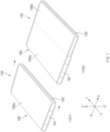
- an electronic device 100 includes display 160 (e.g., a flexible display having at least a portion of flexibility), a first cover 181, and a second cover 182.
- the first cover 181 may serve as a fixed cover to which one side of the display 160 is fixed.
- the second cover 182 may be moved in a first direction (e.g., x-axis direction) or in a second direction (e.g., -x-axis direction opposite to the first direction), based on the first cover 181.
- a first display region 160a of the first size may be disposed to be directed upward (z-axis direction).
- the display 160 may include the first display region 160a of the first size that is exposed to the outside.
- the first cover 181 may be disposed to surround at least a portion of one side edge of the first display region 160a (e.g., based on the illustrated drawing, at least a portion of the first display region 160a in the second direction (-x-axis direction), at least a portion in a third direction (y-axis direction), at least a portion in a fourth direction (-y-axis direction), and at least a portion in a fifth direction (-z-axis direction, which is opposite to the z-axis direction)).
- the first display region 160a and at least a portion of a second display region 160b to be extended may be disposed to be wound on the inner side of at least one of the first cover 181 and the second cover 182, or may be disposed to be unfolded.
- pixels of the first display region 160a may be disposed such that the surface thereof emitting light is directed toward the front (z-axis direction), and at least a portion of the upper surface of the second display region 160b on which pixels are disposed is directed toward the back (-z-axis direction).
- a portion of the second display region 160b may be disposed to be bent.
- the exposed region of the display 160 may be expanded.
- a state 103 e.g., a state in which the second cover 182 has slid in order to expand the region of the display 160
- the display 160 may include the first display region 160a of the first size and the second display region 160b of a second size, which are exposed to the outside (directed upward (z-axis direction)).
- the first size of the first display region 160a and the second size of the second display region 160b may be the same.
- the first size may be larger than the second size.
- the second size may vary according to a sliding distance or a moving distance of the second cover 182.
- the display 160 maintains a partially wound state in the state 101, and in the state 103, at least a portion that has been in the wound state may have an unfolded state.
- the second cover 182 may be disposed to surround at least a portion of the second display region 160b in the first direction (x-axis direction), at least a portion in the third direction (y-axis direction), at least a portion in the fourth direction (-y-axis direction), and at least a portion in the fifth direction (-z-axis direction).
- the second cover 182 is at least partially connected to the inside of the first cover 181, and slides along the inner surface of the first cover 181 in any one of the first direction (x-axis direction) and the second direction (-x-axis direction).
- the first cover 181 and the second cover 182 may be disposed to surround an edge of the display 160 while the first cover 181 and the second cover 182 are sliding.
- Various electronic elements related to driving the display 160, electronic elements related to various user functions supported by the electronic device 100, batteries, and so on may be disposed on the inner side of the first cover 181 and the second cover 182.
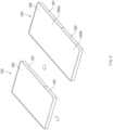
- FIG. 2 is a diagram illustrating an exploded perspective view of configurations of an electronic device based on a first direction according to an example of the disclosure.
- FIG. 3 is a diagram illustrating an exploded perspective view of configurations of an electronic device based on a second direction according to an example of the disclosure.
- FIG. 2 is a diagram illustrating a structure in which the display 160 is disposed on the covers 181 and 182 from the fifth direction (-z-axis direction) to a sixth direction (z-axis direction)
- FIG. 3 is a diagram illustrating a structure in which the covers 181 and 182 and the display 160 are disposed in a direction opposite to that in FIG. 2 .
- the electronic device 100 may include the display 160, a first display support member 140, a sliding structure 150, a first sliding support member 121a, a first sliding member 121b, a second sliding support member 122a, a second sliding member 122b, an actuator 130, an actuator support member 131, the first cover 181, and the second cover 182.
- the display 160 may have a plurality of pixels arranged in a matrix form, and at least a portion of the display 160 may be provided in a flexible form.
- the display 160 may include a panel layer on which a plurality of pixels are arranged and a screen is displayed, and an outer protective layer over the panel layer.
- the outer protective layer may be formed of a polymer structure (e.g., polyimide) or glass.
- the display 160 may further include a touch panel layer. As described in FIG. 1 , the display 160 may include the first display region 160a and the second display region 160b.
- At least a portion of the second display region 160b may be disposed to be wound on the inner side of the second cover 182 in the state 101, and may be exposed outside the second cover 182 in the state 103. While at least a portion of the second display region 160b is disposed to be wound and thus to be bent relative to a first rotation shaft 155 (or a rolling gear part or a rotation shaft member), the remaining portion may be disposed on the back surface of the first display region 160a.
- One side of the display 160 (e.g., at least a portion of the second display region 160b) may be mounted on the inner side of at least one of the first cover 181 and the second cover 182. In this state, one side end of the display 160 disposed on the inner side of the electronic device 100 may be coupled (or fastened, or connected, or engaged)) to an elastic member.
- the elastic force of the elastic member acts on the display 160 as a tension while the second display region 160b of the display 160 is exposed to the outside, and thus the repulsive force in the bent portion of the display 160 is canceled out. In this way, the wound portion of the display 160 may be maintained uniformly.
- the first display support member 140 may have a specified rigidity and may support the display 160.
- at least a portion of the first display support member 140 may be provided as aluminum or an aluminum alloy, and a surface thereof facing the display 160 may be formed to be flat.
- at least a portion of the first display support member 140 may be provided as an injection material (e.g., a structure containing magnesium).
- a first surface of the first display support member 140 e.g., a surface observed in the z-axis direction
- may face the back surface of the first display region 160a e.g., a surface observed in the -z-axis direction).
- a second surface of the first display support member 140 may be disposed to face the upper surface of the sliding structure 150 (e.g., a surface observed in the z-axis direction).
- the first display support member 140 may have a sidewall 140a formed on one side, and may include a flat region 140b perpendicular to the sidewall 140a and supporting the portion of the display 160. Accordingly, a cross-section of the first display support member 140 may be provided in an "L" shape.
- the sidewall 140a may be coupled with at least one of a guard member 120 of the first cover 181 and a fixing part 151 of the sliding structure 150.
- additional sidewalls for supporting the first sliding member 121b and the second sliding member 122b may be disposed on both side edges of the first display support member 140 (e.g., both side edges adjacent to the sidewall 140a), respectively.
- At least one guide rail 140c may be formed on the back surface of the first display support member 140 (a surface observed in the -z-axis direction).
- the guide rail 140c may be provided as a groove having a predetermined length on the back surface of the first display support member 140. At least portions of the first sliding support member 121a and the second sliding support member 122a may be seated on the guide rail 140c.
- At least a portion of the sliding structure 150 may be coupled with the second cover 182, and may be slid with sliding of the second cover 182.
- the sliding structure 150 may be moved by an actuator.
- a separate physical button capable of instructing the driving of the actuator may be disposed in the electronic device 100 or a menu related to driving the actuator may be output on the display screen of the display 160.
- the disposition direction of the second display region 160b of the display 160 fixed to the sliding structure 150 may be changed from the sixth direction (-z-axis direction) to the fifth direction (z-axis direction).
- the sliding structure 150 may include the fixing part 151, a second display support member 152, a first panel support 170, the first rotation shaft 155, and a connecting part 153.
- the fixing part 151 may be formed to have a predetermined length in the third direction (y-axis direction) (e.g., a length corresponding to the long axis of the sidewall 140a of the first display support member 140).
- the fixing part 151 may be disposed side by side with the guard member 120 of the second cover 182.
- the fixing part 151 may be disposed side by side with the sidewall 140a of the first display support member 140.
- At least a portion of the fixing part 151 may be coupled with at least one of the guard member 120 and the sidewall 140a.
- at least one hole penetrating the front and back surfaces (e.g., from the y-axis direction to the -y-axis direction) may be disposed on one side of the fixing part 151.
- the second display support member 152 may be disposed such that the upper surface (e.g., a surface observed in the z-axis) faces the lower surface (e.g., a surface observed in the -z-axis) of the first display support member 140 in the state 101.
- the lower surface of the second display support member 152 e.g., the surface observed in the -z-axis
- At least one hardware e.g., a printed circuit board and a battery
- driving the electronic device 100 may be disposed on the inner side of the second display support member 152.
- the second display support member 152 may be moved together with the movement of the second cover 182. While the second display support member 152 is moved in the first direction (x-axis direction), at least a portion of the first panel support 170, which has been in a state of being disposed on the lower surface of the second display support member 152, may be moved to the upper surface of the second display support member 152.
- the first panel support 170 may have a shape in which a plurality of protrusions (or pillars, long bars, or slates) with a predetermined length in the third direction (y-axis direction) are disposed at certain intervals. At least a portion of the first panel support 170 may form a track, and may move (or slide) a portion of the display (e.g., the second display region 160b) disposed on the track. The length of one side of the protrusions may correspond to the length of one side of the display 160.
- the first panel support 170 may be disposed to surround at least a portion of the second display support member 152.
- the plurality of protrusions constituting the first panel support 170 may be disposed such that the surface facing the back surface of the display 160 is flat, and the part disposed to be directed toward the inner side of the sliding structure 150 (e.g., the part facing the first rotation shaft 155) may be formed to protrude.
- the lower surface (e.g., one surface of the protrusions facing the sliding structure) of the first panel support 170 peaks and troughs of gear may be repeatedly formed.
- the protrusions disposed on the upper surface of the second display support member 152 may be continuously disposed with other neighboring protrusions, forming a flat surface.
- protrusions disposed at the position facing the first rotation shaft 155 may be disposed to be spaced apart from neighboring protrusions at certain intervals.
- the first panel support 170 may include a connecting chain or connecting shaft connecting a plurality of protrusions. At least one of the plurality of protrusions may be provided as a material that reacts to magnetic force (e.g., a magnetic material (an object that forms an attractive force in reaction to magnetic force) or a magnet).
- the first rotation shaft 155 (or a rolling gear part, or the rotation shaft member) may have a length similar to the length of one side of the second display support member 152 and may be disposed side by side with one side edge of the second display support member 152.
- the first rotation shaft 155 may be provided in a cylindrical rod shape.
- the centers of both sides of the first rotation shaft 155 may be formed to protrude more than the surroundings.
- the protruding centers of both sides of the first rotation shaft 155 may be mounted on one side of the second cover 182. Accordingly, the first rotation shaft 155 may rotate while the second cover 182 is moved in the first direction (x-axis direction). At least a portion of the first rotation shaft 155 may be geared with the first panel support 170.
- the first rotation shaft 155 may contact at least a portion of the first panel support 170.
- the disposition form of the first panel support 170 may be changed while the first rotation shaft 155 rotates.
- the first rotation shaft 155 rotates in the first rotating direction (e.g., the right hand winding direction)
- at least a portion of the first panel support 170 may be moved to the upper surface (the surface observed in the z-axis direction) of the second display support member 152.
- the first rotation shaft 155 rotates in the second rotating direction (e.g., the left hand winding direction)
- at least a portion of the first panel support 170 may be moved between the lower surface of the second display support member 152 (or second display support member 152) and the second cover 182.
- the connecting part 153 may connect the fixing part 151 and the second display support member 152.
- one side of the connecting part 153 may be fixed to a certain position of the fixing part 151 (e.g., the center of the fixing part 151), and the other side may be coupled (or fastened, or connected, or engaged) to the lower surface of the second display support member 152 (e.g., surface that may be observed in the z-axis).
- the connecting part 153 may include a gear pattern having at least one peak and trough.
- the connecting part 153 may be implemented in a rack form.
- the second display support member 152 may be moved in the first direction (x-axis direction) and the second direction (-x-axis direction) with being coupled (or fastened, or connected, or engaged) to the connecting part 153.
- the first sliding support member 121a may be mounted on one side of the first display support member 140 and may be coupled to the first sliding member 121b such that the first sliding member 121b is movable.
- the first sliding support member 121a may be disposed side by side with one side of the second display support member 152 (e.g., a side surface observed in the -y-axis direction) and may include a support part seated on the guide rail 140c and a protruding part protruding from the support part to allow at least a portion to fasten to the first sliding member 121b.
- At least a portion of the first sliding member 121b may be coupled to the first sliding support member (121a) seated on the guide rail (140c), and may be coupled with the second display support member 152.
- the first sliding member 121b may be formed to correspond at least partially to the shape of one side of the second display support member 152 (e.g., a side surface observed in the -y-axis direction).
- the second sliding support member 122a has the same shape as the first sliding support member 121a, but may be disposed at a position spaced apart from the first sliding support member 121a by a predetermined distance.
- the second sliding support member 122a may be disposed at a position opposite to the first sliding support member 121a based on the sliding structure 150.
- the second sliding support member 122a may be seated at least partially on the guide rail 140c formed on the first display support member 140 and may be coupled to the second sliding member 122b.
- the second sliding member 122b may be coupled to one side of the second sliding support member 122a and may be coupled with the second display support member 152.
- the second sliding member 122b may be disposed at a position opposite to the first sliding member 121b based on the sliding structure 150.
- the actuator 130 may generate power by receiving electric power from a battery included in the electronic device 100.
- a pinion gear may be disposed on one side of the actuator 130, and the pinion gear may operate on a rack formed on one side of the sliding structure 150. Accordingly, according to the operation, the actuator 130 may operate to be disposed close to the guard member 120 in the state 101, and may operate to be moved in a direction away from the guard member 120 (or a direction toward the second cover 182) in the state 103.
- the actuator 130 may be disposed in the longitudinal direction (e.g., y-axis or -y-axis direction) of the sliding structure 150. In the illustrated drawing, two actuators are illustrated as being arranged on the same axis.
- the actuator support member 131 may support one side of the body of the actuator 130.
- the actuator support member 131 may be moved together with the movement of the actuator 130.
- the first cover 181 may include a cover base 181a including a bottom surface on which at least a portion of the sliding structure 150 is seated and sidewalls disposed to surround edges of the sliding structure 150 (e.g., side portions disposed at the ends in the y-axis direction and the -y-axis direction), the guard member 120 fixing the first display support member 140 and the fixing part 151 in a state where the sidewall 140a of the first display support member 140 and the fixing part 151 are disposed, and a fastening part 181b fastening the guard member 120.
- a cover base 181a including a bottom surface on which at least a portion of the sliding structure 150 is seated and sidewalls disposed to surround edges of the sliding structure 150 (e.g., side portions disposed at the ends in the y-axis direction and the -y-axis direction), the guard member 120 fixing the first display support member 140 and the fixing part 151 in a state where the sidewall 140a of the first display support member 140 and the fixing part
- the fastening part 181b is disposed on the side of the first cover 181 in the second direction (-x-axis direction), and at least a portion of the first cover 181 in the second direction (-x-axis direction) may be closed as the guard member 120 is coupled to the fastening part 181b.
- the first cover 181 may be in an open state in the first direction (x-axis direction), and the second cover 182 may be coupled to the first cover 181 in the first direction (x-axis direction).
- the second cover 182 may be coupled to the first cover 181 in the first direction (x-axis direction).
- the second cover 182 may include a bottom surface on which at least a portion of the sliding structure 150 is seated and sidewalls (e.g., sidewalls disposed in the x-direction, the y-axis direction, and the -y-axis direction) that surround side surfaces of the sliding structure 150.
- the second cover 182 may be moved in the first direction (x-axis direction) or the second direction (-x-axis direction) in a state in which the sliding structure 150 is seated thereon. In this case, the disposition form and position of the second cover 182 may be changed according to the actuator operation.
- At least some of the plurality of protrusions constituting the first panel support 170 may include a magnet member or a magnetic material. Further, at least a portion of the first rotation shaft 155 may include a magnet member or a magnetic material. Accordingly, the first panel support 170 on which the display 160 of the electronic device 100 is seated may prevent the display 160 from being lifted by magnetic force in the process of coming into contact with the first rotation shaft 155 (or offset the repulsive force caused by warping of the display). As a result, the flatness of the display 160 around the first rotation shaft 155 may be maintained within a specified range.
- the electronic device 100 may include a display, a first cover surrounding one side of the display, a panel support disposed on one side of the display, a rotation shaft contacting the panel support, and a second cover coupled to the first cover and the rotation shaft, and other components may be added or excluded as necessary.
- the elastic members, magnetic force-related members (at least one of a magnetic material that reacts to magnetic force or a magnet), and gear structures described in FIGS. 4A to 8 may be selectively further added or excluded.
- the electronic device 100 described above may include an actuator, and may operate such that the second display region 160b is automatically expanded or reduced according to the actuator control.
- the sliding structure 150 and the first rotation shaft 155 which are engaged with the second cover 182, may be rotated, which may, in turn, make the second display region 160b expanded or reduced in a manual manner.
- FIG. 4A is a diagram illustrating a portion of an internal structure of an electronic device according to an example of the disclosure.
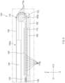
- FIG. 4B is a diagram illustrating at least a portion of a cross-section of an electronic device taken along line A-A' of FIG. 4A according to an example of the disclosure.
- FIG. 4A is a diagram illustrating at least a portion of the back surface of the electronic device with the cover removed.
- the electronic device 100 may include at least the first display support member 140, the first panel support 170, the actuator 130, and the first rotation shaft 155, and an elastic member 159. According to various examples of the disclosure, the electronic device 100 may further include the display 160, the first cover 181, and the second cover 182, as described above with reference to FIGS. 2 and 3 .
- a fixing groove 141 allowing one side of the elastic member 159 to be fixed may be disposed.
- the elastic member 159 is provided in a spring shape
- at least a portion of the fixing groove 141 may have a ring shape on which one side of the elastic member is mounted to fix one side of the elastic member 159.
- the fixing groove 141 may also be provided in a hole shape including a ring.
- One side of the elastic member 159 may be fixed to the first display support member 140, and the other side of the elastic member 159 may be fixed to one side of the first panel support 170.
- the elastic member 159 may have a stretched state. In this way, the stretched elastic member 159 may exert a greater elastic force to the first panel support 170.
- the elastic force of the elastic member 159 acts such that one side end of the first panel support 170 is directed in the second direction (-x-axis direction), at least a portion of the display 160 and the first panel support 170 may maintain a predetermined flatness.
- One or more elastic members 159 may be disposed based on at least one of the size of the first panel support 170 and the stretching characteristics of the first panel support 170 (e.g., the magnitude of the stretching force or the amount of the tension). For example, two elastic members 159 may be disposed on both side edges of the first panel support 170, respectively, as illustrated. Alternatively, one elastic member 159 may be disposed at a central position of the first panel support 170. Alternatively, three or more elastic members 159 may be connected to the first panel support 170.
- the elastic member 159 may be formed of at least one of various materials capable of providing an elastic force of a specified magnitude or more, such as spring and rubber.
- the first panel support 170 may include connecting holes 171 through which the elastic member 159 is possible to be connected.
- the first panel support 170 may be constituted by a plurality of protrusions which are sequentially disposed.
- protrusions disposed on one side e.g., an end in the -x-axis direction
- the number of connecting holes 171 may be formed to correspond to the number of elastic members 159. For example, if a plurality of the elastic members 159 are disposed, a plurality of the connecting holes 171 may also be disposed.
- FIG. 5 is a diagram illustrating a portion of a configuration of an electronic device related to maintenance of flatness according to an example of the disclosure.
- the electronic device 100 may include the display 160, the first panel support 170, and the first rotation shaft 155.
- FIG. 5 illustrates only a portion of the configuration of the electronic device 100, and may further include at least some of other configurations of the electronic device described with reference to FIGS. 2 and 3 .
- the display 160 may correspond to the display 160 described with reference to FIGS. 1 to 3 .
- the display 160 may include the first display region 160a whose disposition state is fixed regardless of sliding of the second cover 182, and the second display region 160b whose the disposition state is changed with sliding of the second cover 182.
- the first panel support 170 may be disposed under the second display region 160b of the display 160 to support the second display region 160b.
- the first panel support 170 may include a plurality of protrusions 170a, ..., and 170b.
- the plurality of protrusions 170a, ..., and 170b may be formed such that the upper surface (the surface facing the second display region 160b) and the lower surface (the surface opposite to the second display region 160b) have the same area.
- the plurality of protrusions 170a, ..., and 170b may be disposed to be spaced apart at certain intervals.
- the upper surface in the plurality of protrusions 170a, ..., and 170b, the upper surface may have a relatively wide surface as compared to the lower surface.
- the first gap 501a between individual upper surfaces of the plurality of protrusions 170a, ..., and 170b may be formed to be smaller than a second gap 501b between individual lower surfaces.
- the lower surfaces of the plurality of protrusions 170a, ..., and 170b may move while contacting the first rotation shaft 155.
- At least some of the plurality of protrusions 170a, ..., and 170b included in the first panel support 170 may be formed of a magnetic material (e.g., an iron, an iron alloy, or an object magnetized to a magnet, which forms an attractive force in reaction to a magnetic force).
- a magnetic material e.g., an iron, an iron alloy, or an object magnetized to a magnet, which forms an attractive force in reaction to a magnetic force.
- at least one protrusion disposed adjacent to the boundary between the first display region 160a and the second display region 160b may be formed of a magnetic material.
- a first protrusion group 170a (or at least one first protrusion) disposed close to the side edge of the first display region 160a in the first direction (x-axis direction) may be formed of a magnetic material. Accordingly, in the rolled state (e.g., the state 101 of FIG. 1 ), where the electronic device 100 is disposed such that only the first display region 160a is exposed, the first protrusion group 170a may maintain the contact state with the first rotation shaft 155. As the first protrusion group 170a maintains the contact state with the first rotation shaft 155 based on the magnetic force, the first display region 160a may maintain flatness within a specified size.
- the first protrusion group 170a and a second protrusion group 170b are illustrated in a form including a plurality of protrusions, respectively; however, the disclosure is not limited thereto. At least one of the first protrusion group 170a and the second protrusion group 170b may include a plurality of protrusions, respectively, or may include only one protrusion, respectively, and when the first protrusion group 170a (or the second protrusion group 170b) includes one protrusion, the second protrusion group 170b (or the first protrusion group 170a) may include a plurality of protrusions.
- the second protrusion group 170b including at least one protrusion disposed on one side edge of the second display region 160b (e.g., an end edge in the opposite direction based on a boundary with the first display region 160a) may maintain the contact state with the first rotation shaft 155.
- the second protrusion group 170b may maintain flatness within a specified range.
- At least a portion of the first rotation shaft 155 may be in contact with at least some of the plurality of protrusions of the first panel support 170.
- the first rotation shaft 155 may rotate with the operation of the actuator 130.
- the first rotation shaft 155 may rotate with the movement of the second cover 182 in the x-axis direction. While the first rotation shaft 155 rotates, the positions of the protrusions of the first panel support 170 contacting the first rotation shaft 155 may be changed.
- At least a portion of the first rotation shaft 155 may be formed of a magnetic member (or permanent magnet or electromagnet).
- the first rotation shaft 155 may be provided in a cylindrical rod shape.
- the first rotation shaft 155 may at least partially include a magnet member that contacts an upper end (end in the y-axis direction) and a lower end (end in the -y-axis direction) of the second display region 160b.
- a certain portion 155a disposed close to the end of the second display region 160b in the y-axis direction, a certain portion 155b disposed close to the end of the second display region 160b in the -y-axis direction, and the central part 155c of the second display region 160b may include a magnet member of a specified size.
- the first rotation shaft 155 may be provided in a cylindrical rod shape, may include a coil wound a certain number of times on the inner side, and may become an electromagnet by using electric power supplied from a battery of the electronic device 100.
- the processor of the electronic device 100 may perform control such that at least a portion of the first rotation shaft 155 becomes an electromagnet by supplying electric power to the first rotation shaft 155 in at least one of a state in which the second display region 160b is wound (e.g., the state 101 in FIG. 1 ) and a state in which the second display region 160b is unfolded (e.g., the state 103 of FIG. 1 ).
- the first panel support 170 including a plurality of protrusions, at least a portion of which is formed of a magnetic material, contacts the first rotation shaft 155 based on the magnetic force in the state 101 and the state 103, respectively, thereby making it possible to maintain the flatness of the specified size.
- the plurality of protrusions are divided into the first protrusion group 170a and a second protrusion group 170b; however, the number of protrusions belonging to each protrusion group is not limited.
- the first protrusion group 170a may include protrusions disposed relatively close to the first display region 160a
- the second protrusion group 170b may include protrusions disposed relatively far away from the first display region 160a.
- the first protrusion group 170a and the second protrusion group 170b may be described as including all the plurality of protrusions, or additional protrusions may be disposed between the first protrusion group 170a and the second protrusion group 170b.
- protrusions at least partially contacting the first rotation shaft 155 may belong to the first protrusion group 170a. Accordingly, the number of protrusions belonging to the first protrusion group 170a may be changed according to the size of the first rotation shaft 155 or the size of the protrusions and the interval between the protrusions.
- the first panel support 170 described with reference to FIG. 5 may further include at least one elastic member 159, which has been described with reference to FIGS. 4A and 4B .
- the elastic member 159 pulls the first panel support 170 in the second direction (-x-axis direction)
- the lifting of the second display region 160b is eliminated (or the bending repulsion is eliminated), and thus the display 160 may maintain flatness within a specified size.
- at least one of the plurality of protrusions contacts the first rotation shaft 155 by magnetic force, and as a result, the flatness of the display 160 may be further enhanced in addition to the elasticity of the elastic member 159.
- the first protrusion group 170a disposed close to the first display region 160a and the second protrusion group 170b disposed far away from the first display region 160a (or relatively close to the elastic member 159) are formed of a magnetic material; however, the disclosure is not limited thereto.
- all the protrusions included in the first panel support 170 may be formed of a magnetic material, or when a protrusion disclosed closet to the first display region 160a among a plurality of continuously disposed protrusions is designated as first, odd-numbered (or even-numbered) or the N-th protrusions may be formed of a magnetic material and the remaining protrusions may be formed of a non-magnetic material.
- the first rotation shaft 155 may be formed of a magnetic material, and at least some of the plurality of protrusions disposed on the first panel support 170 may be formed of a magnetic member (e.g., permanent magnet).
- At least a portion of at least one of the first rotation shaft 155 and the first panel support 170 may be provided as a magnetic member (e.g., a magnet), and at least a portion of at least one of the rests one may be a magnetic material that generates an attractive force with the magnetic material.
- a magnetic member e.g., a magnet
- at least a portion of the first rotation shaft 155 is formed of a magnetic member
- at least a portion of the first panel support 170 may be formed of a magnetic material.
- at least one of the protrusions constituting the first panel support 170 or at least some of specific protrusions may be formed of a magnetic material.
- At least a portion of the first rotation shaft 155 is formed of a magnetic material
- at least a portion of the first panel support 170 may be formed of a magnetic member.
- at least portions of the first rotation shaft 155 and the first panel support 170 may be all a magnetic member.
- FIG. 6 is a diagram illustrating a portion of a configuration of an electronic device related to prevention of display damage according to an example of the disclosure.
- the electronic device 100 may include the display 160, the first display support member 140, the sliding structure 150, the first panel support 170, and the first rotation shaft 155, the second cover 182, the elastic member 159, and the first magnetic force-related member 158. Furthermore, the electronic device 100 may further include the first cover 181 and the protective member 175.
- the display 160 may include the first display region 160a and the second display region 160b.
- the first display region 160a may include, for example, as illustrated, a region exposed upward (e.g., in the z-axis direction)
- the second display region 160b may include a region disposed between the sliding structure 150 and the second cover 182.
- the first protrusion group 170a disposed at one side end of the first panel support 170 may be disposed to be in contact with the first rotation shaft 155.
- at least one of the one or more protrusions included in the first protrusion group 170a may be formed of a magnetic material, and the first rotation shaft 155 may be formed of a magnet member.
- at least one of one or more protrusions included in the first protrusion group 170a may be formed of a magnetic member and the first rotation shaft 155 may be formed of a magnetic material, as described above with reference to FIG. 5 .
- the first magnetic force-related member 158 is disposed on one side of the sliding structure 150, and, may be disposed at a position adjacent to the back portion of the first panel support 170 in a wound state.
- the first magnetic force-related member 158 may include, for example, a member capable of generating an attractive force to at least some of the plurality of protrusions included in the first panel support 170 (e.g., the second protrusion group 170b).
- the first magnetic force-related member 158 may be formed of a permanent magnet.
- the first magnetic force-related member 158 may move the second display region 160b upward (e.g., the z-axis direction) while the second display region 160b is disposed between the sliding structure 150 and the second cover 182, which makes it possible to prevent at least a portion of the second display region 160b from contacting the second cover 182. Accordingly, the electronic device 100 may prevent the second display region 160b from being damaged by the second cover 182.
- the plurality of protrusions disposed in the second display region 160b may be provided in a configuration capable of forming an attractive force to the first magnetic force-related member 158 (e.g., a magnetic material (an object that forms an attractive force in reaction to magnetic force) or a magnet (an object that directly generates magnetic force)).
- the second protrusion group 170b may include at least some of the remaining protrusions other than those of the first protrusion group 170a.
- the elastic member 159 pulls the second display region 160b in a second direction (-x-axis direction), thereby providing tension to the second display region 160b while reducing friction between the second display region 160b and the second cover 182, which makes it possible to provide support such that the display region of the part on which the first rotation shaft 155 is disposed has a flatness of a specified size or more.
- the protective member 175 may be disposed between the sliding structure 150 and the second cover 182 or between the second display region 160b and the second cover 182. Alternatively, the protective member 175 is formed on at least a portion of the inner surface of the second cover 182 (e.g., a surface observed in the z-side direction), and may be disposed in a region facing the second display region 160b. The protective member 175 may protect at least a portion of the second display region 160b when the display 160 of the electronic device 100 is wound (e.g., the state 101 of FIG. 1 ).
- the protective member 175 may be formed of a material having a friction force equal to or less than a specified size, such as velvet, leather, paper, and wool.
- At least one component 190 (e.g., battery or printed circuit board (PCB)) related to driving the electronic device 100 may be disposed under the protective member 175 (e.g., in the -z-axis direction).
- the at least one component 190 related to driving the electronic device 100 may be disposed in the inner side of the sliding structure 150.
- the protective member 175 may be disposed between the second display region 160b and the at least one component 190 of the electronic device, which makes it possible to prevent at least one of damage to the second display region 160b or damage to the at least one component 190 of the electronic device, caused by friction between the second display region 160b and the at least one component 190 of the electronic device.
- FIG. 7 is a diagram illustrating a portion of a configuration of an electronic device related to maintenance of flatness according to an example of the disclosure.
- the electronic device 100 includes the first display support member 140, the sliding structure 150, the display 160, a second panel support 170a, a second rotation shaft 155a, and may include a second magnetic force-related member 158a.
- the electronic device 100 may further include the protective member 175.
- the electronic device 100 may further include at least one of the components described with reference to FIGS. 1 to 3 .
- the protective member 175 may be disposed between the second display region 160b and the at least one component 190 of the electronic device, which makes it possible to prevent damage caused by friction between the second display region 160b and the at least one component 190 of the electronic device.
- the display 160 includes the first display region 160a whose position is fixed, and the second display region 160b whose position is changed.
- An upper surface (e.g., a surface directed to the z-axis) of the first display support member 140 may be disposed under the display 160.
- the second panel support 170a including a plurality of protrusions is disposed under the second display region 160b of the display 160.
- each protrusion included in the second panel support 170a includes a hook pattern.
- the hook pattern includes a hook ring 170a_1 protruding in a direction opposite to the protruding direction of the hook pattern formed on the second rotation shaft 155a.
- the hook ring 170a_1 of the second panel support 170a may be disposed in the second direction (-x axis) based on the upper surface (e.g., the surface exposed in the z-axis) of the second display region 160b.
- the hook ring 170a_1 of the second panel support 170a disposed in the second display region 160b may be disposed to be directed in the first direction (the x-axis direction).
- the hook ring 170a_1 may be formed on one side of the lower surface of the corresponding protrusion.
- the second rotation shaft 155a is provided in a cylindrical rod shape, and at least one hook pattern 155a_1 may be regularly disposed on the outer surface at certain intervals.
- the hook pattern 155a_1 is formed to correspond to the hook ring 170a_1 formed on the second panel support 170a.
- the hook pattern 155a_1 may be partially disposed on the second rotation shaft 155a.
- the hook pattern 155a_1 may be formed on at least one of one side edge, the other side edge, and the center of the second rotation shaft 155a provided in a cylindrical rod shape.
- the second magnetic force-related member 158a may play the same role as the first magnetic force-related member 158 described above with reference to FIG. 6 .
- the second magnetic force-related member 158a may be disposed adjacent to the second panel support 170a, and may generate an attractive force to at least one of the plurality of protrusions disposed on the second panel support 170a.
- the second magnetic force-related member 158a may be provided as a magnet or a magnetic material, and at least a portion of the second panel support 170a may be provided as a magnetic material or a magnet.
- both the second magnetic force-related member 158a and the second panel support 170a may be formed of a magnet.
- the second magnetic force-related member 158a may include a plurality of magnetic materials or magnets spaced apart at specified intervals.
- the second magnetic force-related member 158a may be provided in a plate shape with a relatively long length in the longitudinal direction (e.g., the longitudinal direction of the rod of the second rotation shaft 155a).
- the second panel support 170a and the second rotation shaft 155a are temporarily ring-coupled in the process of contacting each other, making them to come into close contact with each other. Accordingly, as the second panel support 170a maintains a stable contact state with the second rotation shaft 155a, the second display region 160b in the vicinity of the second rotation shaft 155a does not protrude or bend outward (e.g., z-axis direction), and thus flatness may be kept constant.
- the shape of the hook pattern 155a_1 protruding from the surface of the cylindrical rod includes hook grooves (or recesses) that are cut into a surface of the outside of the cylindrical rod. At least some of the hook grooves are temporarily coupled to hook rings disposed on the panel support while the display 160 is expanded or returned to its original state. Alternatively, when the expansion or reduction of the display 160 is stopped, at least some of the hook holes may maintain a fastened state with the hook rings of the panel support.
- FIG. 8 is a diagram illustrating a portion of a configuration of an electronic device related to maintenance of flatness according to an example of the disclosure.
- the electronic device 100 may include the sliding structure 150, a third panel support 170b, and a third rotation shaft 155b. Furthermore, the electronic device 100 may further include at least one of the components of the electronic device 100 described with reference to FIGS. 1 to 3 .
- the third panel support 170b may include peaks protruding at a specified interval and troughs recessed at a specified interval, below the display 160.
- a substrate portion 170b_1 and protrusions 170b_2 may be integrated with each other.
- at least a portion of the third panel support 170b may be formed of a rubber material or a polymer material.
- the substrate portion 170b_1 of the third panel support 170b maintains a constant thickness, it is possible to prevent the issue that the third panel support 170b is viewed when the display 160 is seen from the outside of the second display region 160b (in the z-axis direction). For example, as described with reference to FIG.
- the gear patterns when the gear patterns are disposed at certain intervals directly on a lower portion of the display 160, the certain intervals are visually recognized as a stripe when viewed from the outside, which may result in deterioration in quality of the display 160 in uniformity.
- the third panel support 170b illustrated in FIG. 8 if the protrusions 170b_2 are integrally formed with the substrate portion 170b_1, the above-mentioned uniformity quality may be improved.
- the third rotation shaft 155b may be provided in a form corresponding to the pattern of the protrusions 170b_2 of the third panel support 170b.
- the third rotation shaft 155b may be provided in a cylindrical rod shape, and a plurality of stripe-shaped protrusions may be disposed on the rod surface. The plurality of stripe-shaped protrusions may be partially formed for each position of the rod.
- At least portions of the third panel support 170b and the third rotation shaft 155b may have magnetism.
- at least portions of the third panel support 170b and the third rotation shaft 155b may be formed of a rubber magnet. Based on this, as the third panel support 170b comes in close contact to the third rotation shaft 155b by magnetic force, the bending of the third panel support 170b on the part of the third rotation shaft 155b is removed, which makes it possible to maintain the flatness of the display 160.
- FIG. 9 is a diagram illustrating a structure of an electronic device related to maintenance of flatness according to an example of the disclosure.
- an electronic device 200 may include a first cover 281, a second cover 282, and a display 260.
- the second cover 282 may be moved in a vertical axis (e.g., an arrow direction in the illustrated drawing).
- the display 260 may be expanded and thus a second display region 260b may be secured in addition to an initial first display region 260a.
- the above-described electronic device 200 may employ structures of the panel support and the rotation shaft described above with reference to FIGS. 4A to 8 . Accordingly, the electronic device 200 may be a roll-type electronic device capable of being expanded in a vertical direction.
- the electronic device 200 may further include at least one of the protective member, the magnetic force-related member, the panel support made of rubber or polymer, and the elastic member mentioned in the above drawings.
- FIG. 10 is a diagram illustrating different structures of extension and reduction of an electronic device according to an example of the disclosure.
- an electronic device 1000 may include at least a display 1160, a first cover 1081, a second cover 1082, a display support member 1140, a sliding structure 1150, a panel support 1170, a first driving unit 1030 (or configuration including the actuators described in FIGS. 2 and 3 ), and a second driving unit 1055 (or configuration including the rotation shaft described in FIGS. 2 and 3 ).
- a display 1160 may have a configuration substantially the same as or similar to the display 160 described above with reference to FIGS. 2 and 3 .
- the display 1160 may be provided in a flexible form, may include a panel layer on which a screen is displayed and an outer protective layer (e.g., a polymer structure or ultra-thin glass) disposed over the panel layer, and additionally, may further include a touch panel layer.
- the display 1160 may include a first display region 1160a whose region size and position are fixed, and a second display region 1160b whose region size and position are changed. One side edge of the first display region 1160a and one side edge of the second display region 1160b may be continuously disposed.
- the second display region 1160b may disposed to extend from one side edge of the first display region 1160a.
- the second display region 1160b may be disposed to be at least partially rolled into the inner side of the second cover 1082 or to be taken out from the inner side of the second cover 1082 to be directed in the same direction as the first display region 1160.
- the display support member 1140 may be disposed under the first display region 1160a, and the panel support 1170 may be disposed at a back surface of the second display region 1160b.
- the first cover 1081 may include a bottom surface on which at least a portion of the sliding structure 1150 is seated and sidewalls disposed to surround side edges of the sliding structure 1150.
- the first cover 1081 may have substantially the same configuration as the first cover 181 described above with reference to FIGS. 2 and 3 .
- the first cover 1081 may have an open state in the first direction (e.g., the right direction in the illustrated drawing), and the second cover 182 may be coupled to the first cover 1081 in the first direction so as to be slidable.
- the second cover 1082 may be coupled to the first cover 1081 in the first direction.
- the second cover 1082 may have substantially the same configuration as the second cover 182 described above with reference to FIGS. 2 and 3 .
- the second cover 1082 may include a bottom surface on which at least a portion of the sliding structure 1150 is seated and sidewalls surrounding the side surfaces of the sliding structure 1150.
- the second cover 1082 may be moved in a first direction or in a second direction opposite to the first direction (e.g., the left direction based on the illustrated drawing) in a state in which the sliding structure 1150 is seated.
- the disposition form or position of the second cover 1082 may be changed according to the operations of the first driving unit 1030 and the second driving unit 1055.
- the display support member 1140 may have a specified rigidity and may support the display 1160. For example, as at least a portion of the surface of the display support member 1140 facing the display 1160 is formed to be flat, the display support member 1140 may be disposed to face the back surface of the display 1160. At least a portion of the display support member 1140 may be seated and fixed in the first cover 1081. For example, the display support member 1140 may be disposed and fixed between the first cover 1081 and the back surface of the display 1160. At least a portion of such a display support member 1140 may be formed of a metal material (e.g., aluminum or aluminum alloy).
- a metal material e.g., aluminum or aluminum alloy
- At least one guide rail 1140c may be formed on the back surface of the display support member 1140 (e.g., at least a portion of the display support member 1140 facing the first driving unit 1030).
- the at least one guide rail 1140c may be provided in a repeated pattern of peaks and troughs of a gear having a predetermined length on the back surface of the display support member 1140.
- At least a portion of a ring gear of the first driving unit 1030 having gear grooves on the outer surface may be seated on the at least one guide rail 1140c.
- the at least one guide rail 1140c may be disposed on at least a portion of the back surface of the display support member 1140 (e.g., a surface opposite to the surface directed toward the display 1160).
- two guide rails may be disposed biasedly toward both edges of the display support member 1140.
- the width of the at least one guide rail 1140c may have a size corresponding to the width of the ring gear of the first driving unit 1030 (e.g., size equal to or greater than the size of the ring gear).
- the length of the at least one guide rail 1140c may have a length corresponding to the maximum extension length of the second cover 1082.
- At least a portion of the sliding structure 1150 may be coupled with the second cover 1082, and may be slid with the sliding of the second cover 1082.
- the sliding structure 1150 may be moved by the operation of the first driving unit 1030.
- a separate physical button capable of instructing the driving of the first driving unit 1030 may be disposed in the electronic device 1000 or a menu related to driving the first driving unit 1030 may be output on the display screen of the display 1160.
- the disposition direction of the second display region 1160b of the display 1160 fixed to the sliding structure 1150 may be changed from a display back surface direction (e.g., a direction opposite to the direction in which the first display region 1160a is directed) to a display front surface direction (e.g., a direction in which the first display region 1160a is directed).
- the sliding structure 1150 may be disposed between the display support member 1140 and the first cover 1081 or at least partially side by side with the display support member 1140, and may have at least some of various structures related to driving the electronic device 1000 disposed inside.
- a portion of the sliding structure 1150 may have an upper surface facing the back surface of the display support member 1140, and may have at least one of a battery, a printed circuit board, a camera, and a sensor disposed inside.
- the sliding structure 1150 may move together with the second cover 1082 in the first direction or in the second direction opposite to the first direction, with the operation of the first driving unit 1030.
- the sliding structure 1150 may have the same structure as at least a portion of the sliding structure 1150 described above with reference to FIGS. 2 and 3 .
- the panel support 1170 may have a shape in which a plurality of protrusions (or pillars, long bars, or slates) having a predetermined length in the third direction, which is opposite to the direction in which the first display region 1160a is directed, are disposed at certain intervals. At least a portion of the panel support 1170 may form a track, and may move (or slide) a portion of the display (e.g., the second display region 1160b) disposed on the track.
- the plurality of protrusions constituting the panel support 1170 may be disposed such that the surface facing the back surface of the display 1160 is flat, and the part disposed to be directed toward the inner side of the sliding structure 1150 (e.g., the part contacting the gear pattern of the second driving unit 1055) may be formed to protrude.
- the lower surface (e.g., one surface of the protrusions facing the sliding structure 1150) of the panel support 1170 peaks and troughs of the gear may be repeatedly formed.
- protrusions disposed at the position facing the gear pattern of the second driving unit 1055 may be disposed to be spaced apart from neighboring protrusions at certain intervals.
- the panel support 1170 may include a connecting chain or connecting shaft connecting a plurality of protrusions. As described above, at least one of the plurality of protrusions of the panel support 1170 may be provided as a material that reacts to magnetic force (e.g., a magnetic material (an object that forms an attractive force in reaction to magnetic force) or a magnet).
- a magnetic material an object that forms an attractive force in reaction to magnetic force
- a magnet e.g., a magnet
- the first driving unit 1030 may generate power by receiving electric power from a battery included in the electronic device 1000.
- the first driving unit 1030 may be at least partially coupled to the at least one guide rail 1140c formed on the back surface of the display support member 1140, and may use the generated power to make the gear work for movement along the at least one guide rail 1140c in the first direction (or the second direction opposite to the first direction).
- the first driving unit 1030 may operate in conjunction with the second driving unit 1055. For example, at least some operations of the first driving unit 1030 may include an operation of rotating the gear in the same direction as the second driving unit 1055.
- the second driving unit 1055 may be disposed to be at least partially coupled to the panel support 1170. Accordingly, at least a portion of the second driving unit 1055 may be disposed under the display 1160 and an operation for extending and winding the second display region 1160b may be performed. In this regard, at least a portion of the second driving unit 1055 may include a gear pattern, and the gear pattern may be coupled (or fastened) to at least a portion of the panel support 1170.
- the second driving unit 1055 may receive electric power from a battery, rotate a body including the gear pattern, and move the panel support 1170 coupled (or fastened) to the gear pattern in the first direction or the second direction, thereby making it possible to control the extension and reduction of the second display region 1160b.
- the second driving unit 1055 may operate in conjunction with the first driving unit 1030. For example, at least some operations of the second driving unit 1055 may operate in the same direction as some operations of the first driving unit 1030.
- the electronic device 1000 may include the first driving unit 1030 and the second driving unit 1055, and while the electronic device 1000 changes from the state 1001 to the state 1003, the first driving unit 1030 may rotate in a first rotation direction (e.g., a rotating direction causing the second cover 1082 to move in the first direction) and the second driving unit 1055 may also rotate in the first rotation direction in the same manner. Accordingly, the electronic device 1000 more stably extends the second cover 1082 by receiving the force required for the extension of the second cover 1082 from the first driving unit 1030 and the second driving unit 1055.
- a first rotation direction e.g., a rotating direction causing the second cover 1082 to move in the first direction
- the second driving unit 1055 may also rotate in the first rotation direction in the same manner. Accordingly, the electronic device 1000 more stably extends the second cover 1082 by receiving the force required for the extension of the second cover 1082 from the first driving unit 1030 and the second driving unit 1055.
- the second driving unit 1055 may also rotate in a second rotation direction. Accordingly, the electronic device 1000 according to an example may provide enough power to move the second cover 1082 while changing from the extended state to the reduced state, thereby making it possible to provide more stable support for winding of the display 1160 and moving of the second cover 1082.
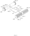
- FIG. 11 is a diagram illustrating at least some of components related to driving units among components of an electronic device according to an example of the disclosure.
- the electronic device 1000 may include the first driving unit 1030, the second driving unit 1055, a printed circuit board 1011, a processor 1012, and a memory 1013.
- the first driving unit 1030 may include a first ring gear 1030_1a, a second ring gear 1030_1b, a first motor 1030_2, a first connecting shaft 1030_3, and a first wire 1030_4. Additionally, a first ring gear body 1030_5a connected to the first ring gear 1030_1a and a second ring gear body 1030_5b connected to the second ring gear 1030_1b may be included.
- the first ring gear 1030_1a is provided in a circular band shape having a predetermined thickness, and may have a shape in which irregularities are regularly arranged on an outer circumferential surface.
- the first motor 1030_2 may be connected to a side surface of the first ring gear 1030_1a. Accordingly, the first ring gear 1030_1a may rotate in the clockwise direction or in the counterclockwise direction, according to the operating direction of the first motor 1030_2.
- the irregularities formed on the outer circumferential surface of the first ring gear 1030_1a may be coupled (or fastened) to the at least one guide rail 1140c formed on the back surface of the display support member 1140 as described above. Accordingly, when the first motor 1030_2 is operated and the first ring gear 1030_1a rotates in the counterclockwise direction, the first ring gear 1030_1a may rotate in the first direction.
- one side of the central shaft may be coupled with one side surface of the first ring gear 1030_1a.
- the first motor 1030_2 may operate by receiving electrical power from a battery (not illustrated) connected to the printed circuit board 1011 via the first wire 1030_4. In this case, the first motor 1030_2 may rotate in the clockwise direction or in the counterclockwise direction according to the operation of the processor 1012.
- the other side of the central shaft of the first motor 1030_2 may be connected to the first connecting shaft 1030_3.
- the first connecting shaft 1030_3 may be connected to the other side of the central shaft of the first motor 1030_2 and one side surface of the second ring gear 1030_1b.
- the first connecting shaft 1030_3 may serve to transmit, to the second ring gear 1030_1b, the force generated while the first motor 1030_2 rotates.
- first wire 1030_4 may be connected to the first motor 1030_2 via the first connecting shaft 1030_3.
- the other side of the first wire 1030_4 may be connected to one side of the printed circuit board 1011.
- the first wire 1030_4 may transmit, to the first motor 1030_2, electric power from the battery of the electronic device 1000. Further, the first wire 1030_4 may transmit, to the first motor 1030_2, a control signal of the processor 1012 mounted on the printed circuit board 1011.
- the first wire 1030_4 may be provided in various forms, such as a cable or an FPCB.
- the second ring gear 1030_1b may be disposed at a position symmetrical to the first ring gear 1030_1a based on a point where the first wire 1030_4 and the first connecting shaft 1030_3 are connected.
- the second ring gear 1030_1b may be provided in substantially the same shape as or similar shape to the first ring gear 1030_1a.
- the second ring gear 1030_1b may be provided in a disc-belt shape having a predetermined width, and irregularities may be regularly formed on the outer circumferential surface.
- the irregularity pattern of the second ring gear 1030_1b may be coupled (or fastened) to the at least one guide rail 1140c formed on the back surface of the display support member 1140.
- the second ring gear 1030_1b may receive, via the first connecting shaft 1030_3, power according to the operation of the first motor 1030_2, and may rotate in the same direction as the first ring gear 1030_1a.
- the second driving unit 1055 may be driven in conjunction with the first driving unit 1030.
- the second driving unit 1055 may include a first gear part 1055_1a, a second gear part 1055_1b, a second motor 1055_2, a second connecting shaft 1055_3, and a second wire 1055_4.
- the outer surface of the first gear part 1055_1a may be formed in a gear pattern.
- the second motor 1055_2 may be disposed inside the first gear part 1055_1a.
- the second motor 1055_2 is connected inside the first gear part 1055_1a, and may be disposed to rotate in a specific direction according to the operation of the second motor 1055_2.
- the second motor 1055_2 includes a central shaft, and the central shaft of the second motor 1055_2 may be fastened to or coupled with an inner end of the first gear part 1055_1a.
- the second motor 1055_2 may be disposed inside the first gear part 1055_1a, and the central shaft of the second motor 1055_2 may be coupled (or fastened) to the first gear part 1055_1a.
- the other side of the second motor 1055_2 may be connected to the second connecting shaft 1055_3.
- the second motor 1055_2 may operate depending on electric power transmitted via the second wire 1055_4, and may transmit power generated according to the operation to the first gear part 1055_1a.
- the second connecting shaft 1055_3 may have one end connected to the central shaft of the second motor 1055_2, and the other end connected to one end of the second gear part 1055_1b.
- the second wire 1055_4 may be disposed in at least either inside or outside the second connecting shaft 1055_3.
- the second wire 1055_4 has one end connected to the second motor 1055_2 via the second connecting shaft 1055_3, and the other end connected to the printed circuit board 1011.
- the second wire 1055_4 may transmit, to the second motor 1055_2, electric power from the battery of the electronic device 1000, and may transmit, to the second motor 1055_2, a control signal of the processor 1012, which is similar to the first wire 1030_4.
- the first motor 1030_2 is disposed on the inner side of the first ring gear 1030_1a, and the second motor 1055_2 is disposed inside the first gear part 1055_1a has been described; however, the disclosure is not limited thereto.
- the first motor 1030_2 may be disposed outside the first ring gear 1030_1a and may be disposed in a structure in which a rotating force is transmitted to the first ring gear 1030_1a.
- the second motor 1055_2 may also be disposed outside the first gear part 1055_1a, and may be disposed in a structure in which the force generated by the operation is transmitted to the first gear part 1055_1a.
- the printed circuit board 1011 may be disposed between the first driving unit 1030 and the second driving unit 1055. According to an example of the disclosure, the printed circuit board 1011 may be connected to the first wire 1030_4 for supplying electric power and control signals to the first driving unit 1030. In addition, the printed circuit board 1011 may be connected to the second wire 1055_4 for supplying electric power and control signals to the second driving unit 1055. According to various examples of the disclosure, the printed circuit board 1011 may be at least partially disposed in the sliding structure 1150 described above, and may move in the first direction or in the second direction opposite to the first direction with the movement of the sliding structure 1150. The processor 1012 and the memory 1013 may be mounted on the printed circuit board 1011.
- the processor 1012 may be mounted on the printed circuit board 1011, generate a control signal according to a user input, and transmit the generated signal to the first motor 1030_2 and the second motor 1055_2.
- the processor 1012 may generate control signals for controlling the rotation speed and direction of the first motor 1030_2, and the rotation speed and direction of the second motor 1055_2, and transmit the generated control signals to the first motor 1030_2 and the second motor 1055_2 via the first wire 1030_4 and the second wire 1055_4, respectively.
- the processor 1012 may generate control signals for controlling the first motor 1030_2 and the second motor 1055_2 to rotate in the same direction to transmit the control signals to the first motor 1030_2 and the second motor 1055_2, respectively.
- the processor 1012 may generate a control signal for making the rotation direction of one of the first motor 1030_2 or the second motor 1055_2 different, and supply the generated control signal to the first motor 1030_2 and the second motor 1055_2.
- FIG. 12 is a flowchart illustrating a method of operating an electronic device according to an example of the disclosure.
- the processor 1012 of the electronic device 1000 may maintain a reduced state of the display 1160 in operation 1201.
- the processor 1012 may adjust the rotation directions of the first motor 1030_2 and the second motor 1055_2 such that the second display region 1160b moves to the inner side of the second cover 1082.
- the processor 1012 may control the first motor 1030_2 and the second motor 1055_2 such that they rotate in the clockwise direction.
- the processor 1012 may determine the number of rotations of the first motor 1030_2 and the second motor 1055_2.
- the processor 1012 may determine, according to the user setting, the first number of rotations used to perform control such that the whole second display region 1160b is displayed on the inner side of the second cover 1082, or the numbers of rotations of at least one of the first motor 1030_2 and the second motor 1055_2 used such that a portion of the second display region 1160b is disposed to be directed in the same direction as the first display region 1160a and only a portion is disposed on the inner side of the second cover 1082.
- the processor 1012 may adjust the numbers of rotations of the first motor 1030_2 and the second motor 1055_2 corresponding to receiving the user input.
- the display 1160 may output a screen interface related to size adjustment of the second display region 1160b.
- the processor 1012 may determine the size adjustment of the second display region 1160b corresponding to the touch input of the user, and may determine the numbers of rotations of the motors corresponding to the size adjustment.
- the processor 1012 may fix the first motor 1030_2 and the second motor 1055_2 after the size adjustment of the second display region 1160b is determined.
- the processor 1012 may perform control such that the first motor 1030_2 is fixed and the second motor 1055_2 further rotates by a predetermined angle in a direction opposite to the reduction direction of the second display region 1160b.
- the processor 1012 may perform control such that the first motor 1030_2 and the second motor 1055_2 rotates by the same number of rotations, and then the second motor 1055_2 further rotates by a predetermined angle in the clockwise direction.
- the processor 1012 may perform control such that the second display region 1160b maintain the flat state without lifting.
- the electronic device 1000 may further include a stopper for fixing the second driving unit 1055 after the second driving unit 1055 is driven by the additional angle in the clockwise direction.
- the stopper may serve to temporarily fix the second driving unit 1055 after the second driving unit 1055 is further rotated by the additional angle. If the electronic device 1000 is extended, the stopper may be disposed to temporarily release the fixing of the second driving unit 1055.
- the processor 1012 may identify whether or not an input signal for extending the display 1160 is generated. If there is no reception of the input signal for extending the display 1160, the processor 1012 may perform control to maintain the state 1201. If the input signal (e.g., a user input) requesting extension of the display 1160 is generated, the processor 1012 may control the first driving unit 1030 and the second driving unit 1055 to be driven in the counterclockwise direction for a first time period in operation 1205. Alternatively, the processor 1012 may control the numbers of rotations of the first motor 1030_2 of the first driving unit 1030 and the second motor 1055_2 of the second driving unit 1055 such that they are rotated by a specified number of rotations.
- the processor 1012 may control the numbers of rotations of the first motor 1030_2 of the first driving unit 1030 and the second motor 1055_2 of the second driving unit 1055 such that they are rotated by a specified number of rotations.
- first driving unit 1030 and the second driving unit 1055 operate for the first time period (or by a first number of rotations)
- the first driving unit 1030 moves in the first direction
- the second driving unit 1055 also moves in the first direction as in the first driving unit 1030, rotating the panel support 1170, which, in turn, the second display region 1160b positioned on the panel support 1170 may be repositioned to be directed in the same direction as that of the first display region 1160a.
- the processor 1012 may stop the first driving unit 1030 and drive the second driving unit 1055 by a first angle in a clockwise direction.
- the first angle may vary depending on the tension of the second display region 1160b.
- the processor 1012 may increase the overall tension of the display 1160 by driving the second driving unit 1055 by the first angle in the clockwise direction, which makes it possible to provide support for maintaining a more flat state.
- the processor 1012 may drive the second driving unit 1055 by the first angle in the counterclockwise direction, and drive the first driving unit 1030 and the second driving unit 1055 for a second time (or by a second number of rotations) in the clockwise direction, thereby changing the display 1160 into the reduced state.
- the second time (or the second number of rotations) may include, for example, a time period substantially the same as the first time period (or the first number of rotations) described above.
- the control method of the electronic device 1000 may process the movement of the second display region 1160b and the second cover 1082 covering it more smoothly by generating and operating power required to expand or reduce the second display region 1160b using the first driving unit 1030 and the second driving unit 1055.
- the electronic device 1000 increases the tension of the display 1160 by fixing the first driving unit 1030 and further rotating the second driving unit 1055 (or the second motor 1055_2) by a specified angle in a clockwise direction in the process of extending or reducing the display 1160, which makes it possible to control the display 1160 to maintain a more flat state.
- an electronic device may include a first cover, a second cover coupled (or fastened) to the first cover to slide, a display in which a size of an exposed region is changed corresponding to the sliding of the second cover, a display support member supporting a first region of the display, a sliding structure at least partially disposed under the display support member, a first driving unit at least partially coupled (or fastened) to a guide rail formed on the bottom of the display support member and moving the sliding structure in a first direction or a second direction opposite to the first direction, a panel support including a plurality of protrusions disposed on a back surface of a second region of the display based on a front surface of the display on which a screen is displayed, a second driving unit contacting at least a portion of the panel support and performing a rotation required for winding of the panel support, and at least one processor configured to control operations of the first driving unit and the second driving unit.
- the processor may control the first driving unit and the second driving unit to operate in a counterclockwise direction for a same time or by a same number of rotations when an event requesting extension of the display occurs.
- the processor may be configured to control the first driving unit to be fixed and the second driving unit to further rotate by the first angle in a clockwise direction, after completing the extension of the display.
- the processor may control the first driving unit and the second driving unit to operate in a clockwise direction for a same time or by a same number of rotations when an event requesting reduction of the display occurs.
- the processor may be configured to control extension or reduction of the display according to a user input or a request to execute a specified application.
Landscapes
- Engineering & Computer Science (AREA)
- Theoretical Computer Science (AREA)
- Physics & Mathematics (AREA)
- Computer Hardware Design (AREA)
- General Physics & Mathematics (AREA)
- General Engineering & Computer Science (AREA)
- Human Computer Interaction (AREA)
- Microelectronics & Electronic Packaging (AREA)
- Mathematical Physics (AREA)
- Automation & Control Theory (AREA)
- Signal Processing (AREA)
- Devices For Indicating Variable Information By Combining Individual Elements (AREA)
- Casings For Electric Apparatus (AREA)
Description
- The invention relates to an electronic device for supporting sliding.
- In recent years, portable electronic devices have been manufactured in a form in which displays of various sizes are mounted in consideration of various purposes such as portability and usability. In addition, in order to meet various needs of users, electronic devices capable of adjusting the size of a display have been developed. As an example, research on flexible displays of a roll structure mounted on the electronic device has been increasingly conducted. The flexible display of the roll structure may be expanded to have a large area by unfolding a rolled region corresponding to the structural deformation of the electronic device.
US2019268455A1 discloses an electronic device including a movable flexible display.US2018103550A1 discloses an expandable display device.KR20140059274A - The electronic device of the roll structure that supports sliding may have a state in which a portion of a display is wound, and a state in which the wound portion of the display is unfolded through the sliding. When the portion of the display changes from the unfolded state to the wound state, the repulsive force against the winding force may act on the wound part of the display. Accordingly, there is a limitation that deformation occurs in which at least a portion of the wound part of the display protrudes more than the surroundings. In addition, while sliding, the portion of the display may be damaged due to friction with other structures of the electronic device.
- Various examples disclosed in the present disclosure provide an electronic device for supporting sliding, which is capable of preventing damage to a display while maintaining flatness of the display.
- The scope of protection is defined by the appended claims. In accordance with an embodiment covered by the claimed invention, an electronic device is provided as defined in independent claim 1.
- It is an aim of certain examples of the disclosure to solve, mitigate or obviate, at least partly, at least one of the problems and/or disadvantages associated with the prior art. Certain examples aim to provide at least one of the advantages described below.
- As described above, according to the examples of the present disclosure, it is possible to maintain the flatness of a display.
- Besides, various effects may be provided that are directly or indirectly identified through the present disclosure.
-
-
FIG. 1 is a diagram illustrating an example of an external shape of an electronic device according to an example. -
FIG. 2 is a diagram illustrating an example of a portion of an internal structure of the electronic device according to an example. -
FIG. 3 is a diagram illustrating an exploded perspective view of components of the electronic device based on a first direction according to an example. -
FIG. 4a is a diagram illustrating an exploded perspective view of components of the electronic device based on a second direction according to an example. -
FIG. 4b is a diagram illustrating at least a portion of a cross section of the electronic device taken along line A-A' inFIG. 4a . -
FIG. 5 is a diagram illustrating a portion of an example configuration of the electronic device related to maintenance of flatness according to an example. -
FIG. 6 is a diagram illustrating a portion of an example configuration of the electronic device related to prevention of display damage according to an example. -
FIG. 7 is a diagram illustrating a portion of another example configuration of the electronic device related to maintenance of flatness according to an example. -
FIG. 8 is a diagram illustrating a portion of yet another example configuration of the electronic device related to maintenance of flatness according to an example. -
FIG. 9 is a diagram illustrating another structure of the electronic device related to maintenance of flatness according to an example. -
FIG. 10 is a diagram illustrating different structures of extension and reduction of the electronic device according to an example. -
FIG. 11 is a diagram illustrating at least some of components related to a driving unit among components of the electronic device according to an example of the present disclosure. -
FIG. 12 is a flowchart illustrating an example of a method of operating the electronic device according to an example. - With respect to the description of the drawings, the same reference numbers may be assigned for the same or corresponding elements.
- Hereinafter, an electronic device according to various examples will be described with reference to the accompanying drawings. In the disclosure, the term user may refer to a person using an electronic device or a device using the electronic device (e.g., an artificial intelligence electronic device).
- The scope of protection is defined by the appended independent claim. Further features are specified by the appended dependent claims.
- The embodiments covered by the claims correspond to
FIG. 1 and7 , whereas the embodiments ofFIG. 4-6 ,8 and10-12 are not covered by the claimed invention. The embodiments of the remaining figures are examples useful for understanding the invention. -
FIG. 1 is a diagram illustrating an external shape of an electronic device according to an example of the disclosure. - Referring to
FIG. 1 , anelectronic device 100, includes display 160 (e.g., a flexible display having at least a portion of flexibility), afirst cover 181, and asecond cover 182. Thefirst cover 181 may serve as a fixed cover to which one side of thedisplay 160 is fixed. Thesecond cover 182 may be moved in a first direction (e.g., x-axis direction) or in a second direction (e.g., -x-axis direction opposite to the first direction), based on thefirst cover 181. As in astate 101, when thefirst cover 181 and thesecond cover 182 overlap by a first width, afirst display region 160a of the first size may be disposed to be directed upward (z-axis direction). Alternatively, in thestate 101, thedisplay 160 may include thefirst display region 160a of the first size that is exposed to the outside. Thefirst cover 181 may be disposed to surround at least a portion of one side edge of thefirst display region 160a (e.g., based on the illustrated drawing, at least a portion of thefirst display region 160a in the second direction (-x-axis direction), at least a portion in a third direction (y-axis direction), at least a portion in a fourth direction (-y-axis direction), and at least a portion in a fifth direction (-z-axis direction, which is opposite to the z-axis direction)). In thestate 101, thefirst display region 160a and at least a portion of asecond display region 160b to be extended may be disposed to be wound on the inner side of at least one of thefirst cover 181 and thesecond cover 182, or may be disposed to be unfolded. In this state, pixels of thefirst display region 160a may be disposed such that the surface thereof emitting light is directed toward the front (z-axis direction), and at least a portion of the upper surface of thesecond display region 160b on which pixels are disposed is directed toward the back (-z-axis direction). A portion of thesecond display region 160b may be disposed to be bent. - If the
second cover 182 is moved in the first direction (x-axis direction) based on thefirst cover 181, the exposed region of thedisplay 160 may be expanded. For example, as in a state 103 (e.g., a state in which thesecond cover 182 has slid in order to expand the region of the display 160), when thefirst cover 181 and thesecond cover 182 overlaps by a second width (e.g., width smaller than the first width), thedisplay 160 may include thefirst display region 160a of the first size and thesecond display region 160b of a second size, which are exposed to the outside (directed upward (z-axis direction)). In thestate 103, the first size of thefirst display region 160a and the second size of thesecond display region 160b may be the same. Alternatively, the first size may be larger than the second size. According to various examples of the disclosure, the second size may vary according to a sliding distance or a moving distance of thesecond cover 182. - The
display 160 maintains a partially wound state in thestate 101, and in thestate 103, at least a portion that has been in the wound state may have an unfolded state. Thesecond cover 182 may be disposed to surround at least a portion of thesecond display region 160b in the first direction (x-axis direction), at least a portion in the third direction (y-axis direction), at least a portion in the fourth direction (-y-axis direction), and at least a portion in the fifth direction (-z-axis direction). Thesecond cover 182 is at least partially connected to the inside of thefirst cover 181, and slides along the inner surface of thefirst cover 181 in any one of the first direction (x-axis direction) and the second direction (-x-axis direction). Thefirst cover 181 and thesecond cover 182 may be disposed to surround an edge of thedisplay 160 while thefirst cover 181 and thesecond cover 182 are sliding. Various electronic elements related to driving thedisplay 160, electronic elements related to various user functions supported by theelectronic device 100, batteries, and so on may be disposed on the inner side of thefirst cover 181 and thesecond cover 182. -
FIG. 2 is a diagram illustrating an exploded perspective view of configurations of an electronic device based on a first direction according to an example of the disclosure.FIG. 3 is a diagram illustrating an exploded perspective view of configurations of an electronic device based on a second direction according to an example of the disclosure. For example,FIG. 2 is a diagram illustrating a structure in which thedisplay 160 is disposed on thecovers FIG. 3 is a diagram illustrating a structure in which thecovers display 160 are disposed in a direction opposite to that inFIG. 2 . - Referring to
FIGS. 2 and3 , theelectronic device 100 according to an example may include thedisplay 160, a firstdisplay support member 140, a slidingstructure 150, a first slidingsupport member 121a, a first slidingmember 121b, a second slidingsupport member 122a, a second slidingmember 122b, anactuator 130, anactuator support member 131, thefirst cover 181, and thesecond cover 182. - According to an example of the disclosure, the
display 160 may have a plurality of pixels arranged in a matrix form, and at least a portion of thedisplay 160 may be provided in a flexible form. According to an example of the disclosure, thedisplay 160 may include a panel layer on which a plurality of pixels are arranged and a screen is displayed, and an outer protective layer over the panel layer. The outer protective layer may be formed of a polymer structure (e.g., polyimide) or glass. Additionally, thedisplay 160 may further include a touch panel layer. As described inFIG. 1 , thedisplay 160 may include thefirst display region 160a and thesecond display region 160b. At least a portion of thesecond display region 160b may be disposed to be wound on the inner side of thesecond cover 182 in thestate 101, and may be exposed outside thesecond cover 182 in thestate 103. While at least a portion of thesecond display region 160b is disposed to be wound and thus to be bent relative to a first rotation shaft 155 (or a rolling gear part or a rotation shaft member), the remaining portion may be disposed on the back surface of thefirst display region 160a. - One side of the display 160 (e.g., at least a portion of the
second display region 160b) may be mounted on the inner side of at least one of thefirst cover 181 and thesecond cover 182. In this state, one side end of thedisplay 160 disposed on the inner side of theelectronic device 100 may be coupled (or fastened, or connected, or engaged)) to an elastic member. - The elastic force of the elastic member acts on the
display 160 as a tension while thesecond display region 160b of thedisplay 160 is exposed to the outside, and thus the repulsive force in the bent portion of thedisplay 160 is canceled out. In this way, the wound portion of thedisplay 160 may be maintained uniformly. - The first
display support member 140 may have a specified rigidity and may support thedisplay 160. For example, at least a portion of the firstdisplay support member 140 may be provided as aluminum or an aluminum alloy, and a surface thereof facing thedisplay 160 may be formed to be flat. According to an example of the disclosure, at least a portion of the firstdisplay support member 140 may be provided as an injection material (e.g., a structure containing magnesium). In thestate 101, a first surface of the first display support member 140 (e.g., a surface observed in the z-axis direction) may face the back surface of thefirst display region 160a (e.g., a surface observed in the -z-axis direction). A second surface of the first display support member 140 (e.g., a surface observed in the - z-axis direction) may be disposed to face the upper surface of the sliding structure 150 (e.g., a surface observed in the z-axis direction). - The first
display support member 140 may have asidewall 140a formed on one side, and may include aflat region 140b perpendicular to thesidewall 140a and supporting the portion of thedisplay 160. Accordingly, a cross-section of the firstdisplay support member 140 may be provided in an "L" shape. Thesidewall 140a may be coupled with at least one of aguard member 120 of thefirst cover 181 and a fixingpart 151 of the slidingstructure 150. According to various examples of the disclosure, additional sidewalls for supporting the first slidingmember 121b and the second slidingmember 122b may be disposed on both side edges of the first display support member 140 (e.g., both side edges adjacent to thesidewall 140a), respectively. - At least one
guide rail 140c may be formed on the back surface of the first display support member 140 (a surface observed in the -z-axis direction). Theguide rail 140c may be provided as a groove having a predetermined length on the back surface of the firstdisplay support member 140. At least portions of the first slidingsupport member 121a and the second slidingsupport member 122a may be seated on theguide rail 140c. - At least a portion of the sliding
structure 150 may be coupled with thesecond cover 182, and may be slid with sliding of thesecond cover 182. Alternatively, the slidingstructure 150 may be moved by an actuator. In this regard, a separate physical button capable of instructing the driving of the actuator may be disposed in theelectronic device 100 or a menu related to driving the actuator may be output on the display screen of thedisplay 160. As at least a portion of the slidingstructure 150 is moved in the first direction while thesecond cover 182 is moved in the first direction (x-axis direction), the disposition direction of thesecond display region 160b of thedisplay 160 fixed to the slidingstructure 150 may be changed from the sixth direction (-z-axis direction) to the fifth direction (z-axis direction). - The sliding
structure 150 may include the fixingpart 151, a seconddisplay support member 152, afirst panel support 170, thefirst rotation shaft 155, and a connectingpart 153. - The fixing
part 151 may be formed to have a predetermined length in the third direction (y-axis direction) (e.g., a length corresponding to the long axis of thesidewall 140a of the first display support member 140). The fixingpart 151 may be disposed side by side with theguard member 120 of thesecond cover 182. Alternatively, the fixingpart 151 may be disposed side by side with thesidewall 140a of the firstdisplay support member 140. At least a portion of the fixingpart 151 may be coupled with at least one of theguard member 120 and thesidewall 140a. In this regard, at least one hole penetrating the front and back surfaces (e.g., from the y-axis direction to the -y-axis direction) may be disposed on one side of the fixingpart 151. - The second
display support member 152 may be disposed such that the upper surface (e.g., a surface observed in the z-axis) faces the lower surface (e.g., a surface observed in the -z-axis) of the firstdisplay support member 140 in thestate 101. The lower surface of the second display support member 152 (e.g., the surface observed in the -z-axis) may be disposed to face at least a portion of the inner side of thefirst cover 181 or the inner side of thesecond cover 182. At least one hardware (e.g., a printed circuit board and a battery) related to driving theelectronic device 100 may be disposed on the inner side of the seconddisplay support member 152. The seconddisplay support member 152 may be moved together with the movement of thesecond cover 182. While the seconddisplay support member 152 is moved in the first direction (x-axis direction), at least a portion of thefirst panel support 170, which has been in a state of being disposed on the lower surface of the seconddisplay support member 152, may be moved to the upper surface of the seconddisplay support member 152. - The
first panel support 170 may have a shape in which a plurality of protrusions (or pillars, long bars, or slates) with a predetermined length in the third direction (y-axis direction) are disposed at certain intervals. At least a portion of thefirst panel support 170 may form a track, and may move (or slide) a portion of the display (e.g., thesecond display region 160b) disposed on the track. The length of one side of the protrusions may correspond to the length of one side of thedisplay 160. Thefirst panel support 170 may be disposed to surround at least a portion of the seconddisplay support member 152. The plurality of protrusions constituting thefirst panel support 170 may be disposed such that the surface facing the back surface of thedisplay 160 is flat, and the part disposed to be directed toward the inner side of the sliding structure 150 (e.g., the part facing the first rotation shaft 155) may be formed to protrude. For example, on the lower surface (e.g., one surface of the protrusions facing the sliding structure) of thefirst panel support 170, peaks and troughs of gear may be repeatedly formed. With the sliding, among the plurality of protrusions constituting thefirst panel support 170, the protrusions disposed on the upper surface of the seconddisplay support member 152 may be continuously disposed with other neighboring protrusions, forming a flat surface. Among the plurality of protrusions constituting thefirst panel support 170, protrusions disposed at the position facing thefirst rotation shaft 155 may be disposed to be spaced apart from neighboring protrusions at certain intervals. Thefirst panel support 170 may include a connecting chain or connecting shaft connecting a plurality of protrusions. At least one of the plurality of protrusions may be provided as a material that reacts to magnetic force (e.g., a magnetic material (an object that forms an attractive force in reaction to magnetic force) or a magnet). - The first rotation shaft 155 (or a rolling gear part, or the rotation shaft member) may have a length similar to the length of one side of the second
display support member 152 and may be disposed side by side with one side edge of the seconddisplay support member 152. Thefirst rotation shaft 155 may be provided in a cylindrical rod shape. The centers of both sides of thefirst rotation shaft 155 may be formed to protrude more than the surroundings. The protruding centers of both sides of thefirst rotation shaft 155 may be mounted on one side of thesecond cover 182. Accordingly, thefirst rotation shaft 155 may rotate while thesecond cover 182 is moved in the first direction (x-axis direction). At least a portion of thefirst rotation shaft 155 may be geared with thefirst panel support 170. Alternatively, thefirst rotation shaft 155 may contact at least a portion of thefirst panel support 170. The disposition form of thefirst panel support 170 may be changed while thefirst rotation shaft 155 rotates. For example, while thefirst rotation shaft 155 rotates in the first rotating direction (e.g., the right hand winding direction), at least a portion of thefirst panel support 170 may be moved to the upper surface (the surface observed in the z-axis direction) of the seconddisplay support member 152. While thefirst rotation shaft 155 rotates in the second rotating direction (e.g., the left hand winding direction), at least a portion of thefirst panel support 170 may be moved between the lower surface of the second display support member 152 (or second display support member 152) and thesecond cover 182. - The connecting
part 153 may connect the fixingpart 151 and the seconddisplay support member 152. In this regard, one side of the connectingpart 153 may be fixed to a certain position of the fixing part 151 (e.g., the center of the fixing part 151), and the other side may be coupled (or fastened, or connected, or engaged) to the lower surface of the second display support member 152 (e.g., surface that may be observed in the z-axis). The connectingpart 153 may include a gear pattern having at least one peak and trough. According to various examples of the disclosure, the connectingpart 153 may be implemented in a rack form. The seconddisplay support member 152 may be moved in the first direction (x-axis direction) and the second direction (-x-axis direction) with being coupled (or fastened, or connected, or engaged) to the connectingpart 153. - The first sliding
support member 121a may be mounted on one side of the firstdisplay support member 140 and may be coupled to the first slidingmember 121b such that the first slidingmember 121b is movable. In this regard, the first slidingsupport member 121a may be disposed side by side with one side of the second display support member 152 (e.g., a side surface observed in the -y-axis direction) and may include a support part seated on theguide rail 140c and a protruding part protruding from the support part to allow at least a portion to fasten to the first slidingmember 121b. - At least a portion of the first sliding
member 121b may be coupled to the first sliding support member (121a) seated on the guide rail (140c), and may be coupled with the seconddisplay support member 152. The first slidingmember 121b may be formed to correspond at least partially to the shape of one side of the second display support member 152 (e.g., a side surface observed in the -y-axis direction). - The second sliding
support member 122a has the same shape as the first slidingsupport member 121a, but may be disposed at a position spaced apart from the first slidingsupport member 121a by a predetermined distance. For example, the second slidingsupport member 122a may be disposed at a position opposite to the first slidingsupport member 121a based on the slidingstructure 150. The second slidingsupport member 122a may be seated at least partially on theguide rail 140c formed on the firstdisplay support member 140 and may be coupled to the second slidingmember 122b. - The second sliding
member 122b may be coupled to one side of the second slidingsupport member 122a and may be coupled with the seconddisplay support member 152. The second slidingmember 122b may be disposed at a position opposite to the first slidingmember 121b based on the slidingstructure 150. - The
actuator 130 may generate power by receiving electric power from a battery included in theelectronic device 100. A pinion gear may be disposed on one side of theactuator 130, and the pinion gear may operate on a rack formed on one side of the slidingstructure 150. Accordingly, according to the operation, theactuator 130 may operate to be disposed close to theguard member 120 in thestate 101, and may operate to be moved in a direction away from the guard member 120 (or a direction toward the second cover 182) in thestate 103. Theactuator 130 may be disposed in the longitudinal direction (e.g., y-axis or -y-axis direction) of the slidingstructure 150. In the illustrated drawing, two actuators are illustrated as being arranged on the same axis. - The
actuator support member 131 may support one side of the body of theactuator 130. Theactuator support member 131 may be moved together with the movement of theactuator 130. - The
first cover 181 may include acover base 181a including a bottom surface on which at least a portion of the slidingstructure 150 is seated and sidewalls disposed to surround edges of the sliding structure 150 (e.g., side portions disposed at the ends in the y-axis direction and the -y-axis direction), theguard member 120 fixing the firstdisplay support member 140 and the fixingpart 151 in a state where thesidewall 140a of the firstdisplay support member 140 and the fixingpart 151 are disposed, and afastening part 181b fastening theguard member 120. Thefastening part 181b is disposed on the side of thefirst cover 181 in the second direction (-x-axis direction), and at least a portion of thefirst cover 181 in the second direction (-x-axis direction) may be closed as theguard member 120 is coupled to thefastening part 181b. Thefirst cover 181 may be in an open state in the first direction (x-axis direction), and thesecond cover 182 may be coupled to thefirst cover 181 in the first direction (x-axis direction). - The
second cover 182 may be coupled to thefirst cover 181 in the first direction (x-axis direction). Thesecond cover 182 may include a bottom surface on which at least a portion of the slidingstructure 150 is seated and sidewalls (e.g., sidewalls disposed in the x-direction, the y-axis direction, and the -y-axis direction) that surround side surfaces of the slidingstructure 150. Thesecond cover 182 may be moved in the first direction (x-axis direction) or the second direction (-x-axis direction) in a state in which the slidingstructure 150 is seated thereon. In this case, the disposition form and position of thesecond cover 182 may be changed according to the actuator operation. - In the
electronic device 100 according to an example having the above-described structure, at least some of the plurality of protrusions constituting thefirst panel support 170 may include a magnet member or a magnetic material. Further, at least a portion of thefirst rotation shaft 155 may include a magnet member or a magnetic material. Accordingly, thefirst panel support 170 on which thedisplay 160 of theelectronic device 100 is seated may prevent thedisplay 160 from being lifted by magnetic force in the process of coming into contact with the first rotation shaft 155 (or offset the repulsive force caused by warping of the display). As a result, the flatness of thedisplay 160 around thefirst rotation shaft 155 may be maintained within a specified range. - Meanwhile, in the above description, a structure in which various components of the
electronic device 100 are disposed has been described; however, the disclosure is not limited thereto. For example, theelectronic device 100 according to an example of the disclosure may include a display, a first cover surrounding one side of the display, a panel support disposed on one side of the display, a rotation shaft contacting the panel support, and a second cover coupled to the first cover and the rotation shaft, and other components may be added or excluded as necessary. In addition, at least one of the elastic members, magnetic force-related members (at least one of a magnetic material that reacts to magnetic force or a magnet), and gear structures described inFIGS. 4A to 8 may be selectively further added or excluded. Theelectronic device 100 described above may include an actuator, and may operate such that thesecond display region 160b is automatically expanded or reduced according to the actuator control. Alternatively, in theelectronic device 100, as thesecond cover 182 is moved in the first direction (x-axis direction) by the external pressure applied to thesecond cover 182, the slidingstructure 150 and thefirst rotation shaft 155, which are engaged with thesecond cover 182, may be rotated, which may, in turn, make thesecond display region 160b expanded or reduced in a manual manner. -
FIG. 4A is a diagram illustrating a portion of an internal structure of an electronic device according to an example of the disclosure.FIG. 4B is a diagram illustrating at least a portion of a cross-section of an electronic device taken along line A-A' ofFIG. 4A according to an example of the disclosure. Here,FIG. 4A is a diagram illustrating at least a portion of the back surface of the electronic device with the cover removed. - Referring to
FIGS. 4A and4B , theelectronic device 100 according to an example may include at least the firstdisplay support member 140, thefirst panel support 170, theactuator 130, and thefirst rotation shaft 155, and anelastic member 159. According to various examples of the disclosure, theelectronic device 100 may further include thedisplay 160, thefirst cover 181, and thesecond cover 182, as described above with reference toFIGS. 2 and3 . - On one side of the first
display support member 140, a fixinggroove 141 allowing one side of theelastic member 159 to be fixed may be disposed. For example, when theelastic member 159 is provided in a spring shape, at least a portion of the fixinggroove 141 may have a ring shape on which one side of the elastic member is mounted to fix one side of theelastic member 159. The fixinggroove 141 may also be provided in a hole shape including a ring. - One side of the
elastic member 159 may be fixed to the firstdisplay support member 140, and the other side of theelastic member 159 may be fixed to one side of thefirst panel support 170. Theelastic member 159 may have a stretched state. In this way, the stretchedelastic member 159 may exert a greater elastic force to thefirst panel support 170. As the elastic force of theelastic member 159 acts such that one side end of thefirst panel support 170 is directed in the second direction (-x-axis direction), at least a portion of thedisplay 160 and thefirst panel support 170 may maintain a predetermined flatness. - One or more
elastic members 159 may be disposed based on at least one of the size of thefirst panel support 170 and the stretching characteristics of the first panel support 170 (e.g., the magnitude of the stretching force or the amount of the tension). For example, twoelastic members 159 may be disposed on both side edges of thefirst panel support 170, respectively, as illustrated. Alternatively, oneelastic member 159 may be disposed at a central position of thefirst panel support 170. Alternatively, three or moreelastic members 159 may be connected to thefirst panel support 170. Theelastic member 159 may be formed of at least one of various materials capable of providing an elastic force of a specified magnitude or more, such as spring and rubber. - The
first panel support 170 may include connectingholes 171 through which theelastic member 159 is possible to be connected. As described above, thefirst panel support 170 may be constituted by a plurality of protrusions which are sequentially disposed. Among the plurality of protrusions, protrusions disposed on one side (e.g., an end in the -x-axis direction) may have a wider width than other adjacent protrusions in order to form the connectingholes 171. The number of connectingholes 171 may be formed to correspond to the number ofelastic members 159. For example, if a plurality of theelastic members 159 are disposed, a plurality of the connectingholes 171 may also be disposed. -
FIG. 5 is a diagram illustrating a portion of a configuration of an electronic device related to maintenance of flatness according to an example of the disclosure. - Referring to
FIG. 5 , theelectronic device 100 according to an example may include thedisplay 160, thefirst panel support 170, and thefirst rotation shaft 155.FIG. 5 illustrates only a portion of the configuration of theelectronic device 100, and may further include at least some of other configurations of the electronic device described with reference toFIGS. 2 and3 . - The
display 160 may correspond to thedisplay 160 described with reference toFIGS. 1 to 3 . For example, thedisplay 160 may include thefirst display region 160a whose disposition state is fixed regardless of sliding of thesecond cover 182, and thesecond display region 160b whose the disposition state is changed with sliding of thesecond cover 182. - The
first panel support 170 may be disposed under thesecond display region 160b of thedisplay 160 to support thesecond display region 160b. Thefirst panel support 170 may include a plurality of protrusions 170a, ..., and 170b. The plurality of protrusions 170a, ..., and 170b may be formed such that the upper surface (the surface facing thesecond display region 160b) and the lower surface (the surface opposite to thesecond display region 160b) have the same area. In this case, the plurality of protrusions 170a, ..., and 170b may be disposed to be spaced apart at certain intervals. According to various examples of the disclosure, in the plurality of protrusions 170a, ..., and 170b, the upper surface may have a relatively wide surface as compared to the lower surface. In this case, thefirst gap 501a between individual upper surfaces of the plurality of protrusions 170a, ..., and 170b may be formed to be smaller than asecond gap 501b between individual lower surfaces. Corresponding to the movement of thesecond cover 182, the lower surfaces of the plurality of protrusions 170a, ..., and 170b may move while contacting thefirst rotation shaft 155. - According to an example of the disclosure, at least some of the plurality of protrusions 170a, ..., and 170b included in the
first panel support 170 may be formed of a magnetic material (e.g., an iron, an iron alloy, or an object magnetized to a magnet, which forms an attractive force in reaction to a magnetic force). According to an example of the disclosure, among the plurality of protrusions 170a, ..., and 170b of thefirst panel support 170, at least one protrusion disposed adjacent to the boundary between thefirst display region 160a and thesecond display region 160b may be formed of a magnetic material. Alternatively, afirst protrusion group 170a (or at least one first protrusion) disposed close to the side edge of thefirst display region 160a in the first direction (x-axis direction) may be formed of a magnetic material. Accordingly, in the rolled state (e.g., thestate 101 ofFIG. 1 ), where theelectronic device 100 is disposed such that only thefirst display region 160a is exposed, thefirst protrusion group 170a may maintain the contact state with thefirst rotation shaft 155. As thefirst protrusion group 170a maintains the contact state with thefirst rotation shaft 155 based on the magnetic force, thefirst display region 160a may maintain flatness within a specified size. In the illustrated drawing, thefirst protrusion group 170a and asecond protrusion group 170b are illustrated in a form including a plurality of protrusions, respectively; however, the disclosure is not limited thereto. At least one of thefirst protrusion group 170a and thesecond protrusion group 170b may include a plurality of protrusions, respectively, or may include only one protrusion, respectively, and when thefirst protrusion group 170a (or thesecond protrusion group 170b) includes one protrusion, thesecond protrusion group 170b (or thefirst protrusion group 170a) may include a plurality of protrusions. - According to various examples of the disclosure, in an unfolded state (e.g., the
state 103 ofFIG. 1 ), where theelectronic device 100 is disposed such that thefirst display region 160a and at least a portion of thesecond display region 160b are exposed together, thesecond protrusion group 170b including at least one protrusion disposed on one side edge of thesecond display region 160b (e.g., an end edge in the opposite direction based on a boundary with thefirst display region 160a) may maintain the contact state with thefirst rotation shaft 155. As thesecond protrusion group 170b maintains the contact state with thefirst rotation shaft 155 based on the magnetic force, thefirst display region 160a and thesecond display region 160b may maintain flatness within a specified range. - At least a portion of the
first rotation shaft 155 may be in contact with at least some of the plurality of protrusions of thefirst panel support 170. Thefirst rotation shaft 155 may rotate with the operation of theactuator 130. Alternatively, thefirst rotation shaft 155 may rotate with the movement of thesecond cover 182 in the x-axis direction. While thefirst rotation shaft 155 rotates, the positions of the protrusions of thefirst panel support 170 contacting thefirst rotation shaft 155 may be changed. At least a portion of thefirst rotation shaft 155 may be formed of a magnetic member (or permanent magnet or electromagnet). According to an example of the disclosure, thefirst rotation shaft 155 may be provided in a cylindrical rod shape. Thefirst rotation shaft 155 may at least partially include a magnet member that contacts an upper end (end in the y-axis direction) and a lower end (end in the -y-axis direction) of thesecond display region 160b. For example, in thefirst rotation shaft 155, at least one of acertain portion 155a disposed close to the end of thesecond display region 160b in the y-axis direction, acertain portion 155b disposed close to the end of thesecond display region 160b in the -y-axis direction, and thecentral part 155c of thesecond display region 160b may include a magnet member of a specified size. - According to various examples of the disclosure, the
first rotation shaft 155 may be provided in a cylindrical rod shape, may include a coil wound a certain number of times on the inner side, and may become an electromagnet by using electric power supplied from a battery of theelectronic device 100. According to an example of the disclosure, the processor of theelectronic device 100 may perform control such that at least a portion of thefirst rotation shaft 155 becomes an electromagnet by supplying electric power to thefirst rotation shaft 155 in at least one of a state in which thesecond display region 160b is wound (e.g., thestate 101 inFIG. 1 ) and a state in which thesecond display region 160b is unfolded (e.g., thestate 103 ofFIG. 1 ). Accordingly, thefirst panel support 170 including a plurality of protrusions, at least a portion of which is formed of a magnetic material, contacts thefirst rotation shaft 155 based on the magnetic force in thestate 101 and thestate 103, respectively, thereby making it possible to maintain the flatness of the specified size. - In the illustrated drawing, the plurality of protrusions are divided into the
first protrusion group 170a and asecond protrusion group 170b; however, the number of protrusions belonging to each protrusion group is not limited. For example, thefirst protrusion group 170a may include protrusions disposed relatively close to thefirst display region 160a, and thesecond protrusion group 170b may include protrusions disposed relatively far away from thefirst display region 160a. Thefirst protrusion group 170a and thesecond protrusion group 170b may be described as including all the plurality of protrusions, or additional protrusions may be disposed between thefirst protrusion group 170a and thesecond protrusion group 170b. According to various examples of the disclosure, in a state in which a portion of thedisplay 160 is wound (e.g., a state before the sliding of thesecond cover 182 for expanding the display region), protrusions at least partially contacting thefirst rotation shaft 155 may belong to thefirst protrusion group 170a. Accordingly, the number of protrusions belonging to thefirst protrusion group 170a may be changed according to the size of thefirst rotation shaft 155 or the size of the protrusions and the interval between the protrusions. - The
first panel support 170 described with reference toFIG. 5 may further include at least oneelastic member 159, which has been described with reference toFIGS. 4A and4B . In this case, as theelastic member 159 pulls thefirst panel support 170 in the second direction (-x-axis direction), the lifting of thesecond display region 160b is eliminated (or the bending repulsion is eliminated), and thus thedisplay 160 may maintain flatness within a specified size. In this state, at least one of the plurality of protrusions contacts thefirst rotation shaft 155 by magnetic force, and as a result, the flatness of thedisplay 160 may be further enhanced in addition to the elasticity of theelastic member 159. - Meanwhile, an example has been described above in which, among the plurality of protrusions included in the
first panel support 170, thefirst protrusion group 170a disposed close to thefirst display region 160a and thesecond protrusion group 170b disposed far away from thefirst display region 160a (or relatively close to the elastic member 159) are formed of a magnetic material; however, the disclosure is not limited thereto. For example, all the protrusions included in thefirst panel support 170 may be formed of a magnetic material, or when a protrusion disclosed closet to thefirst display region 160a among a plurality of continuously disposed protrusions is designated as first, odd-numbered (or even-numbered) or the N-th protrusions may be formed of a magnetic material and the remaining protrusions may be formed of a non-magnetic material. In addition, thefirst rotation shaft 155 may be formed of a magnetic material, and at least some of the plurality of protrusions disposed on thefirst panel support 170 may be formed of a magnetic member (e.g., permanent magnet). - According to various examples of the disclosure, at least a portion of at least one of the
first rotation shaft 155 and thefirst panel support 170 may be provided as a magnetic member (e.g., a magnet), and at least a portion of at least one of the rests one may be a magnetic material that generates an attractive force with the magnetic material. For example, if at least a portion of thefirst rotation shaft 155 is formed of a magnetic member, at least a portion of thefirst panel support 170 may be formed of a magnetic material. Alternatively, at least one of the protrusions constituting thefirst panel support 170 or at least some of specific protrusions may be formed of a magnetic material. Alternatively, if at least a portion of thefirst rotation shaft 155 is formed of a magnetic material, at least a portion of thefirst panel support 170 may be formed of a magnetic member. Alternatively, at least portions of thefirst rotation shaft 155 and thefirst panel support 170 may be all a magnetic member. -
FIG. 6 is a diagram illustrating a portion of a configuration of an electronic device related to prevention of display damage according to an example of the disclosure. - Referring to
FIG. 6 , theelectronic device 100 according to an example may include thedisplay 160, the firstdisplay support member 140, the slidingstructure 150, thefirst panel support 170, and thefirst rotation shaft 155, thesecond cover 182, theelastic member 159, and the first magnetic force-relatedmember 158. Furthermore, theelectronic device 100 may further include thefirst cover 181 and theprotective member 175. - The
display 160 may include thefirst display region 160a and thesecond display region 160b. When theelectronic device 100 is in the state of being wound (e.g., thestate 101 ofFIG. 1 or the state before the sliding of thesecond cover 182 for expanding the display 160), thefirst display region 160a may include, for example, as illustrated, a region exposed upward (e.g., in the z-axis direction), and thesecond display region 160b may include a region disposed between the slidingstructure 150 and thesecond cover 182. Thefirst protrusion group 170a disposed at one side end of the first panel support 170 (e.g., a left region of thesecond display region 160b, (e.g., a region disposed adjacent to thefirst display region 160a)) may be disposed to be in contact with thefirst rotation shaft 155. Here, at least one of the one or more protrusions included in thefirst protrusion group 170a may be formed of a magnetic material, and thefirst rotation shaft 155 may be formed of a magnet member. Alternatively, at least one of one or more protrusions included in thefirst protrusion group 170a may be formed of a magnetic member and thefirst rotation shaft 155 may be formed of a magnetic material, as described above with reference toFIG. 5 . - The first magnetic force-related
member 158 is disposed on one side of the slidingstructure 150, and, may be disposed at a position adjacent to the back portion of thefirst panel support 170 in a wound state. The first magnetic force-relatedmember 158, may include, for example, a member capable of generating an attractive force to at least some of the plurality of protrusions included in the first panel support 170 (e.g., thesecond protrusion group 170b). According to an example of the disclosure, the first magnetic force-relatedmember 158 may be formed of a permanent magnet. The first magnetic force-relatedmember 158 may move thesecond display region 160b upward (e.g., the z-axis direction) while thesecond display region 160b is disposed between the slidingstructure 150 and thesecond cover 182, which makes it possible to prevent at least a portion of thesecond display region 160b from contacting thesecond cover 182. Accordingly, theelectronic device 100 may prevent thesecond display region 160b from being damaged by thesecond cover 182. In this regard, at least some of the plurality of protrusions (e.g., thesecond protrusion group 170b) disposed in thesecond display region 160b may be provided in a configuration capable of forming an attractive force to the first magnetic force-related member 158 (e.g., a magnetic material (an object that forms an attractive force in reaction to magnetic force) or a magnet (an object that directly generates magnetic force)). In the above description, thesecond protrusion group 170b may include at least some of the remaining protrusions other than those of thefirst protrusion group 170a. - The
elastic member 159 pulls thesecond display region 160b in a second direction (-x-axis direction), thereby providing tension to thesecond display region 160b while reducing friction between thesecond display region 160b and thesecond cover 182, which makes it possible to provide support such that the display region of the part on which thefirst rotation shaft 155 is disposed has a flatness of a specified size or more. - The
protective member 175 may be disposed between the slidingstructure 150 and thesecond cover 182 or between thesecond display region 160b and thesecond cover 182. Alternatively, theprotective member 175 is formed on at least a portion of the inner surface of the second cover 182 (e.g., a surface observed in the z-side direction), and may be disposed in a region facing thesecond display region 160b. Theprotective member 175 may protect at least a portion of thesecond display region 160b when thedisplay 160 of theelectronic device 100 is wound (e.g., thestate 101 ofFIG. 1 ). Theprotective member 175 may be formed of a material having a friction force equal to or less than a specified size, such as velvet, leather, paper, and wool. At least one component 190 (e.g., battery or printed circuit board (PCB)) related to driving theelectronic device 100 may be disposed under the protective member 175 (e.g., in the -z-axis direction). According to various examples of the disclosure, the at least onecomponent 190 related to driving theelectronic device 100 may be disposed in the inner side of the slidingstructure 150. Theprotective member 175 may be disposed between thesecond display region 160b and the at least onecomponent 190 of the electronic device, which makes it possible to prevent at least one of damage to thesecond display region 160b or damage to the at least onecomponent 190 of the electronic device, caused by friction between thesecond display region 160b and the at least onecomponent 190 of the electronic device. -
FIG. 7 is a diagram illustrating a portion of a configuration of an electronic device related to maintenance of flatness according to an example of the disclosure. - Referring to
FIG. 7 , theelectronic device 100 according to an embodiment covered by the claims includes the firstdisplay support member 140, the slidingstructure 150, thedisplay 160, asecond panel support 170a, asecond rotation shaft 155a, and may include a second magnetic force-relatedmember 158a. Alternatively, theelectronic device 100 may further include theprotective member 175. According to various examples of the disclosure, theelectronic device 100 may further include at least one of the components described with reference toFIGS. 1 to 3 . According to various examples of the disclosure, theprotective member 175 may be disposed between thesecond display region 160b and the at least onecomponent 190 of the electronic device, which makes it possible to prevent damage caused by friction between thesecond display region 160b and the at least onecomponent 190 of the electronic device. - The
display 160 includes thefirst display region 160a whose position is fixed, and thesecond display region 160b whose position is changed. An upper surface (e.g., a surface directed to the z-axis) of the firstdisplay support member 140 may be disposed under thedisplay 160. Thesecond panel support 170a including a plurality of protrusions is disposed under thesecond display region 160b of thedisplay 160. - The lower surface of each protrusion included in the
second panel support 170a (e.g., the surface directed to the -z axis) includes a hook pattern. The hook pattern includes a hook ring 170a_1 protruding in a direction opposite to the protruding direction of the hook pattern formed on thesecond rotation shaft 155a. According to an example of the disclosure, the hook ring 170a_1 of thesecond panel support 170a may be disposed in the second direction (-x axis) based on the upper surface (e.g., the surface exposed in the z-axis) of thesecond display region 160b. According to various examples of the disclosure, when thesecond display region 160b is disposed between thesecond cover 182 and the slidingstructure 150, the hook ring 170a_1 of thesecond panel support 170a disposed in thesecond display region 160b may be disposed to be directed in the first direction (the x-axis direction). The hook ring 170a_1 may be formed on one side of the lower surface of the corresponding protrusion. - The
second rotation shaft 155a is provided in a cylindrical rod shape, and at least one hook pattern 155a_1 may be regularly disposed on the outer surface at certain intervals. The hook pattern 155a_1 is formed to correspond to the hook ring 170a_1 formed on thesecond panel support 170a. According to various examples of the disclosure, the hook pattern 155a_1 may be partially disposed on thesecond rotation shaft 155a. For example, the hook pattern 155a_1 may be formed on at least one of one side edge, the other side edge, and the center of thesecond rotation shaft 155a provided in a cylindrical rod shape. - The second magnetic force-related
member 158a may play the same role as the first magnetic force-relatedmember 158 described above with reference toFIG. 6 . For example, the second magnetic force-relatedmember 158a may be disposed adjacent to thesecond panel support 170a, and may generate an attractive force to at least one of the plurality of protrusions disposed on thesecond panel support 170a. In this regard, the second magnetic force-relatedmember 158a may be provided as a magnet or a magnetic material, and at least a portion of thesecond panel support 170a may be provided as a magnetic material or a magnet. Alternatively, both the second magnetic force-relatedmember 158a and thesecond panel support 170a may be formed of a magnet. The second magnetic force-relatedmember 158a may include a plurality of magnetic materials or magnets spaced apart at specified intervals. The second magnetic force-relatedmember 158a may be provided in a plate shape with a relatively long length in the longitudinal direction (e.g., the longitudinal direction of the rod of thesecond rotation shaft 155a). - In the
electronic device 100 having the above-described structure, thesecond panel support 170a and thesecond rotation shaft 155a are temporarily ring-coupled in the process of contacting each other, making them to come into close contact with each other. Accordingly, as thesecond panel support 170a maintains a stable contact state with thesecond rotation shaft 155a, thesecond display region 160b in the vicinity of thesecond rotation shaft 155a does not protrude or bend outward (e.g., z-axis direction), and thus flatness may be kept constant. - Meanwhile, in the above description, the shape of the hook pattern 155a_1 protruding from the surface of the cylindrical rod includes hook grooves (or recesses) that are cut into a surface of the outside of the cylindrical rod. At least some of the hook grooves are temporarily coupled to hook rings disposed on the panel support while the
display 160 is expanded or returned to its original state. Alternatively, when the expansion or reduction of thedisplay 160 is stopped, at least some of the hook holes may maintain a fastened state with the hook rings of the panel support. -
FIG. 8 is a diagram illustrating a portion of a configuration of an electronic device related to maintenance of flatness according to an example of the disclosure. - Referring to
FIG. 8 , theelectronic device 100 according to an example may include the slidingstructure 150, athird panel support 170b, and athird rotation shaft 155b. Furthermore, theelectronic device 100 may further include at least one of the components of theelectronic device 100 described with reference toFIGS. 1 to 3 . - The
third panel support 170b may include peaks protruding at a specified interval and troughs recessed at a specified interval, below thedisplay 160. In thethird panel support 170b, for example, a substrate portion 170b_1 and protrusions 170b_2 may be integrated with each other. For example, at least a portion of thethird panel support 170b may be formed of a rubber material or a polymer material. As the substrate portion 170b_1 of thethird panel support 170b maintains a constant thickness, it is possible to prevent the issue that thethird panel support 170b is viewed when thedisplay 160 is seen from the outside of thesecond display region 160b (in the z-axis direction). For example, as described with reference toFIG. 7 , when the gear patterns are disposed at certain intervals directly on a lower portion of thedisplay 160, the certain intervals are visually recognized as a stripe when viewed from the outside, which may result in deterioration in quality of thedisplay 160 in uniformity. As in thethird panel support 170b illustrated inFIG. 8 , if the protrusions 170b_2 are integrally formed with the substrate portion 170b_1, the above-mentioned uniformity quality may be improved. - The
third rotation shaft 155b may be provided in a form corresponding to the pattern of the protrusions 170b_2 of thethird panel support 170b. For example, thethird rotation shaft 155b may be provided in a cylindrical rod shape, and a plurality of stripe-shaped protrusions may be disposed on the rod surface. The plurality of stripe-shaped protrusions may be partially formed for each position of the rod. - According to various examples of the disclosure, at least portions of the
third panel support 170b and thethird rotation shaft 155b may have magnetism. For example, at least portions of thethird panel support 170b and thethird rotation shaft 155b may be formed of a rubber magnet. Based on this, as thethird panel support 170b comes in close contact to thethird rotation shaft 155b by magnetic force, the bending of thethird panel support 170b on the part of thethird rotation shaft 155b is removed, which makes it possible to maintain the flatness of thedisplay 160. -
FIG. 9 is a diagram illustrating a structure of an electronic device related to maintenance of flatness according to an example of the disclosure. - Referring to
FIG. 9 , anelectronic device 200 according to an example may include afirst cover 281, asecond cover 282, and adisplay 260. Thesecond cover 282 may be moved in a vertical axis (e.g., an arrow direction in the illustrated drawing). In this case, as illustrated, thedisplay 260 may be expanded and thus asecond display region 260b may be secured in addition to an initialfirst display region 260a. The above-describedelectronic device 200 may employ structures of the panel support and the rotation shaft described above with reference toFIGS. 4A to 8 . Accordingly, theelectronic device 200 may be a roll-type electronic device capable of being expanded in a vertical direction. Theelectronic device 200 may further include at least one of the protective member, the magnetic force-related member, the panel support made of rubber or polymer, and the elastic member mentioned in the above drawings. -
FIG. 10 is a diagram illustrating different structures of extension and reduction of an electronic device according to an example of the disclosure. - Referring to
FIG. 10 , anelectronic device 1000 according to an example may include at least adisplay 1160, afirst cover 1081, asecond cover 1082, adisplay support member 1140, a slidingstructure 1150, apanel support 1170, a first driving unit 1030 (or configuration including the actuators described inFIGS. 2 and3 ), and a second driving unit 1055 (or configuration including the rotation shaft described inFIGS. 2 and3 ). - A
display 1160 may have a configuration substantially the same as or similar to thedisplay 160 described above with reference toFIGS. 2 and3 . For example, thedisplay 1160 may be provided in a flexible form, may include a panel layer on which a screen is displayed and an outer protective layer (e.g., a polymer structure or ultra-thin glass) disposed over the panel layer, and additionally, may further include a touch panel layer. Thedisplay 1160 may include afirst display region 1160a whose region size and position are fixed, and asecond display region 1160b whose region size and position are changed. One side edge of thefirst display region 1160a and one side edge of thesecond display region 1160b may be continuously disposed. For example, thesecond display region 1160b may disposed to extend from one side edge of thefirst display region 1160a. Thesecond display region 1160b may be disposed to be at least partially rolled into the inner side of thesecond cover 1082 or to be taken out from the inner side of thesecond cover 1082 to be directed in the same direction as thefirst display region 1160. Thedisplay support member 1140 may be disposed under thefirst display region 1160a, and thepanel support 1170 may be disposed at a back surface of thesecond display region 1160b. - The
first cover 1081 may include a bottom surface on which at least a portion of the slidingstructure 1150 is seated and sidewalls disposed to surround side edges of the slidingstructure 1150. Thefirst cover 1081 may have substantially the same configuration as thefirst cover 181 described above with reference toFIGS. 2 and3 . Thefirst cover 1081 may have an open state in the first direction (e.g., the right direction in the illustrated drawing), and thesecond cover 182 may be coupled to thefirst cover 1081 in the first direction so as to be slidable. - The
second cover 1082 may be coupled to thefirst cover 1081 in the first direction. Thesecond cover 1082 may have substantially the same configuration as thesecond cover 182 described above with reference toFIGS. 2 and3 . For example, thesecond cover 1082 may include a bottom surface on which at least a portion of the slidingstructure 1150 is seated and sidewalls surrounding the side surfaces of the slidingstructure 1150. Thesecond cover 1082 may be moved in a first direction or in a second direction opposite to the first direction (e.g., the left direction based on the illustrated drawing) in a state in which the slidingstructure 1150 is seated. In this case, the disposition form or position of thesecond cover 1082 may be changed according to the operations of thefirst driving unit 1030 and thesecond driving unit 1055. - The
display support member 1140 may have a specified rigidity and may support thedisplay 1160. For example, as at least a portion of the surface of thedisplay support member 1140 facing thedisplay 1160 is formed to be flat, thedisplay support member 1140 may be disposed to face the back surface of thedisplay 1160. At least a portion of thedisplay support member 1140 may be seated and fixed in thefirst cover 1081. For example, thedisplay support member 1140 may be disposed and fixed between thefirst cover 1081 and the back surface of thedisplay 1160. At least a portion of such adisplay support member 1140 may be formed of a metal material (e.g., aluminum or aluminum alloy). According to an example of the disclosure, at least a portion of thedisplay support member 1140 may be provided as an injection material (e.g., a structure containing magnesium). In astate 1001, a first surface of the display support member 1140 (e.g., a surface facing the back surface of the display 1160) may be disposed to face the back surface of thefirst display region 1160a, and a second surface of thedisplay support member 1140 opposite to the first surface of thedisplay support member 1140 may be disposed to face the upper surface of the slidingstructure 1150. Thedisplay support member 1140 may be provided to have a cross section of an "L" shape which is rotated by 90 degrees in the counterclockwise direction. - At least one
guide rail 1140c may be formed on the back surface of the display support member 1140 (e.g., at least a portion of thedisplay support member 1140 facing the first driving unit 1030). The at least oneguide rail 1140c may be provided in a repeated pattern of peaks and troughs of a gear having a predetermined length on the back surface of thedisplay support member 1140. At least a portion of a ring gear of thefirst driving unit 1030 having gear grooves on the outer surface may be seated on the at least oneguide rail 1140c. The at least oneguide rail 1140c may be disposed on at least a portion of the back surface of the display support member 1140 (e.g., a surface opposite to the surface directed toward the display 1160). For example, two guide rails may be disposed biasedly toward both edges of thedisplay support member 1140. The width of the at least oneguide rail 1140c may have a size corresponding to the width of the ring gear of the first driving unit 1030 (e.g., size equal to or greater than the size of the ring gear). The length of the at least oneguide rail 1140c may have a length corresponding to the maximum extension length of thesecond cover 1082. - At least a portion of the sliding
structure 1150 may be coupled with thesecond cover 1082, and may be slid with the sliding of thesecond cover 1082. Alternatively, the slidingstructure 1150 may be moved by the operation of thefirst driving unit 1030. In this regard, a separate physical button capable of instructing the driving of thefirst driving unit 1030 may be disposed in theelectronic device 1000 or a menu related to driving thefirst driving unit 1030 may be output on the display screen of thedisplay 1160. As at least a portion of the slidingstructure 1150 is moved in the first direction as in astate 1003 while thesecond cover 1082 is moved in the first direction, the disposition direction of thesecond display region 1160b of thedisplay 1160 fixed to the slidingstructure 1150 may be changed from a display back surface direction (e.g., a direction opposite to the direction in which thefirst display region 1160a is directed) to a display front surface direction (e.g., a direction in which thefirst display region 1160a is directed). - The sliding
structure 1150 may be disposed between thedisplay support member 1140 and thefirst cover 1081 or at least partially side by side with thedisplay support member 1140, and may have at least some of various structures related to driving theelectronic device 1000 disposed inside. For example, a portion of the slidingstructure 1150 may have an upper surface facing the back surface of thedisplay support member 1140, and may have at least one of a battery, a printed circuit board, a camera, and a sensor disposed inside. The slidingstructure 1150 may move together with thesecond cover 1082 in the first direction or in the second direction opposite to the first direction, with the operation of thefirst driving unit 1030. The slidingstructure 1150 may have the same structure as at least a portion of the slidingstructure 1150 described above with reference toFIGS. 2 and3 . - The
panel support 1170 may have a shape in which a plurality of protrusions (or pillars, long bars, or slates) having a predetermined length in the third direction, which is opposite to the direction in which thefirst display region 1160a is directed, are disposed at certain intervals. At least a portion of thepanel support 1170 may form a track, and may move (or slide) a portion of the display (e.g., thesecond display region 1160b) disposed on the track. The plurality of protrusions constituting thepanel support 1170 may be disposed such that the surface facing the back surface of thedisplay 1160 is flat, and the part disposed to be directed toward the inner side of the sliding structure 1150 (e.g., the part contacting the gear pattern of the second driving unit 1055) may be formed to protrude. For example, on the lower surface (e.g., one surface of the protrusions facing the sliding structure 1150) of thepanel support 1170, peaks and troughs of the gear may be repeatedly formed. Among the plurality of protrusions constituting thepanel support 1170, protrusions disposed at the position facing the gear pattern of thesecond driving unit 1055 may be disposed to be spaced apart from neighboring protrusions at certain intervals. Thepanel support 1170 may include a connecting chain or connecting shaft connecting a plurality of protrusions. As described above, at least one of the plurality of protrusions of thepanel support 1170 may be provided as a material that reacts to magnetic force (e.g., a magnetic material (an object that forms an attractive force in reaction to magnetic force) or a magnet). - The
first driving unit 1030 may generate power by receiving electric power from a battery included in theelectronic device 1000. Thefirst driving unit 1030 may be at least partially coupled to the at least oneguide rail 1140c formed on the back surface of thedisplay support member 1140, and may use the generated power to make the gear work for movement along the at least oneguide rail 1140c in the first direction (or the second direction opposite to the first direction). Thefirst driving unit 1030 may operate in conjunction with thesecond driving unit 1055. For example, at least some operations of thefirst driving unit 1030 may include an operation of rotating the gear in the same direction as thesecond driving unit 1055. - The
second driving unit 1055 may be disposed to be at least partially coupled to thepanel support 1170. Accordingly, at least a portion of thesecond driving unit 1055 may be disposed under thedisplay 1160 and an operation for extending and winding thesecond display region 1160b may be performed. In this regard, at least a portion of thesecond driving unit 1055 may include a gear pattern, and the gear pattern may be coupled (or fastened) to at least a portion of thepanel support 1170. Thesecond driving unit 1055 may receive electric power from a battery, rotate a body including the gear pattern, and move thepanel support 1170 coupled (or fastened) to the gear pattern in the first direction or the second direction, thereby making it possible to control the extension and reduction of thesecond display region 1160b. Thesecond driving unit 1055 may operate in conjunction with thefirst driving unit 1030. For example, at least some operations of thesecond driving unit 1055 may operate in the same direction as some operations of thefirst driving unit 1030. - As described above, the
electronic device 1000 according to an example may include thefirst driving unit 1030 and thesecond driving unit 1055, and while theelectronic device 1000 changes from thestate 1001 to thestate 1003, thefirst driving unit 1030 may rotate in a first rotation direction (e.g., a rotating direction causing thesecond cover 1082 to move in the first direction) and thesecond driving unit 1055 may also rotate in the first rotation direction in the same manner. Accordingly, theelectronic device 1000 more stably extends thesecond cover 1082 by receiving the force required for the extension of thesecond cover 1082 from thefirst driving unit 1030 and thesecond driving unit 1055. Similarly for thefirst driving unit 1030 and thesecond driving unit 1055, in the process of theelectronic device 1000 returning from thestate 1003 to thestate 1001, while thefirst driving unit 1030 rotates in the second rotation direction opposite to the first rotation direction, thesecond driving unit 1055 may also rotate in a second rotation direction. Accordingly, theelectronic device 1000 according to an example may provide enough power to move thesecond cover 1082 while changing from the extended state to the reduced state, thereby making it possible to provide more stable support for winding of thedisplay 1160 and moving of thesecond cover 1082. -
FIG. 11 is a diagram illustrating at least some of components related to driving units among components of an electronic device according to an example of the disclosure. - Referring to
FIG. 11 , theelectronic device 1000 according to an example may include thefirst driving unit 1030, thesecond driving unit 1055, a printedcircuit board 1011, aprocessor 1012, and amemory 1013. - The
first driving unit 1030 may include a first ring gear 1030_1a, a second ring gear 1030_1b, a first motor 1030_2, a first connecting shaft 1030_3, and a first wire 1030_4. Additionally, a first ring gear body 1030_5a connected to the first ring gear 1030_1a and a second ring gear body 1030_5b connected to the second ring gear 1030_1b may be included. - The first ring gear 1030_1a is provided in a circular band shape having a predetermined thickness, and may have a shape in which irregularities are regularly arranged on an outer circumferential surface. The first motor 1030_2 may be connected to a side surface of the first ring gear 1030_1a. Accordingly, the first ring gear 1030_1a may rotate in the clockwise direction or in the counterclockwise direction, according to the operating direction of the first motor 1030_2. The irregularities formed on the outer circumferential surface of the first ring gear 1030_1a may be coupled (or fastened) to the at least one
guide rail 1140c formed on the back surface of thedisplay support member 1140 as described above. Accordingly, when the first motor 1030_2 is operated and the first ring gear 1030_1a rotates in the counterclockwise direction, the first ring gear 1030_1a may rotate in the first direction. - In the first motor 1030_2, one side of the central shaft may be coupled with one side surface of the first ring gear 1030_1a. The first motor 1030_2 may operate by receiving electrical power from a battery (not illustrated) connected to the printed
circuit board 1011 via the first wire 1030_4. In this case, the first motor 1030_2 may rotate in the clockwise direction or in the counterclockwise direction according to the operation of theprocessor 1012. The other side of the central shaft of the first motor 1030_2 may be connected to the first connecting shaft 1030_3. - The first connecting shaft 1030_3 may be connected to the other side of the central shaft of the first motor 1030_2 and one side surface of the second ring gear 1030_1b. The first connecting shaft 1030_3 may serve to transmit, to the second ring gear 1030_1b, the force generated while the first motor 1030_2 rotates.
- One side of the first wire 1030_4 may be connected to the first motor 1030_2 via the first connecting shaft 1030_3. The other side of the first wire 1030_4 may be connected to one side of the printed
circuit board 1011. The first wire 1030_4 may transmit, to the first motor 1030_2, electric power from the battery of theelectronic device 1000. Further, the first wire 1030_4 may transmit, to the first motor 1030_2, a control signal of theprocessor 1012 mounted on the printedcircuit board 1011. The first wire 1030_4 may be provided in various forms, such as a cable or an FPCB. - The second ring gear 1030_1b may be disposed at a position symmetrical to the first ring gear 1030_1a based on a point where the first wire 1030_4 and the first connecting shaft 1030_3 are connected. The second ring gear 1030_1b may be provided in substantially the same shape as or similar shape to the first ring gear 1030_1a. For example, the second ring gear 1030_1b may be provided in a disc-belt shape having a predetermined width, and irregularities may be regularly formed on the outer circumferential surface. The irregularity pattern of the second ring gear 1030_1b may be coupled (or fastened) to the at least one
guide rail 1140c formed on the back surface of thedisplay support member 1140. The second ring gear 1030_1b may receive, via the first connecting shaft 1030_3, power according to the operation of the first motor 1030_2, and may rotate in the same direction as the first ring gear 1030_1a. - The
second driving unit 1055 may be driven in conjunction with thefirst driving unit 1030. Thesecond driving unit 1055 may include a first gear part 1055_1a, a second gear part 1055_1b, a second motor 1055_2, a second connecting shaft 1055_3, and a second wire 1055_4. - The outer surface of the first gear part 1055_1a may be formed in a gear pattern. The second motor 1055_2 may be disposed inside the first gear part 1055_1a. The second motor 1055_2 is connected inside the first gear part 1055_1a, and may be disposed to rotate in a specific direction according to the operation of the second motor 1055_2. In this regard, the second motor 1055_2 includes a central shaft, and the central shaft of the second motor 1055_2 may be fastened to or coupled with an inner end of the first gear part 1055_1a.
- The second motor 1055_2 may be disposed inside the first gear part 1055_1a, and the central shaft of the second motor 1055_2 may be coupled (or fastened) to the first gear part 1055_1a. The other side of the second motor 1055_2 may be connected to the second connecting shaft 1055_3. The second motor 1055_2 may operate depending on electric power transmitted via the second wire 1055_4, and may transmit power generated according to the operation to the first gear part 1055_1a.
- The second connecting shaft 1055_3 may have one end connected to the central shaft of the second motor 1055_2, and the other end connected to one end of the second gear part 1055_1b. In addition, the second wire 1055_4 may be disposed in at least either inside or outside the second connecting shaft 1055_3.
- The second wire 1055_4 has one end connected to the second motor 1055_2 via the second connecting shaft 1055_3, and the other end connected to the printed
circuit board 1011. The second wire 1055_4 may transmit, to the second motor 1055_2, electric power from the battery of theelectronic device 1000, and may transmit, to the second motor 1055_2, a control signal of theprocessor 1012, which is similar to the first wire 1030_4. - On the other hand, in the above description, an example in which the first motor 1030_2 is disposed on the inner side of the first ring gear 1030_1a, and the second motor 1055_2 is disposed inside the first gear part 1055_1a has been described; however, the disclosure is not limited thereto. For example, the first motor 1030_2 may be disposed outside the first ring gear 1030_1a and may be disposed in a structure in which a rotating force is transmitted to the first ring gear 1030_1a. Similarly to the first motor 1030_2, the second motor 1055_2 may also be disposed outside the first gear part 1055_1a, and may be disposed in a structure in which the force generated by the operation is transmitted to the first gear part 1055_1a.
- The printed
circuit board 1011 may be disposed between thefirst driving unit 1030 and thesecond driving unit 1055. According to an example of the disclosure, the printedcircuit board 1011 may be connected to the first wire 1030_4 for supplying electric power and control signals to thefirst driving unit 1030. In addition, the printedcircuit board 1011 may be connected to the second wire 1055_4 for supplying electric power and control signals to thesecond driving unit 1055. According to various examples of the disclosure, the printedcircuit board 1011 may be at least partially disposed in the slidingstructure 1150 described above, and may move in the first direction or in the second direction opposite to the first direction with the movement of the slidingstructure 1150. Theprocessor 1012 and thememory 1013 may be mounted on the printedcircuit board 1011. - The
processor 1012 may be mounted on the printedcircuit board 1011, generate a control signal according to a user input, and transmit the generated signal to the first motor 1030_2 and the second motor 1055_2. For example, theprocessor 1012 may generate control signals for controlling the rotation speed and direction of the first motor 1030_2, and the rotation speed and direction of the second motor 1055_2, and transmit the generated control signals to the first motor 1030_2 and the second motor 1055_2 via the first wire 1030_4 and the second wire 1055_4, respectively. According to various examples of the disclosure, theprocessor 1012 may generate control signals for controlling the first motor 1030_2 and the second motor 1055_2 to rotate in the same direction to transmit the control signals to the first motor 1030_2 and the second motor 1055_2, respectively. Alternatively, theprocessor 1012 may generate a control signal for making the rotation direction of one of the first motor 1030_2 or the second motor 1055_2 different, and supply the generated control signal to the first motor 1030_2 and the second motor 1055_2. - The
memory 1013 may store various setting values related to driving theelectronic device 1000. For example, thememory 1013 may store setting values for controlling the first motor 1030_2 and the second motor 1055_2 when theelectronic device 1000 switches between thestate 1001 and thestate 1003. Alternatively, thememory 1013 may store event values set to perform expansion or reduction of thesecond display region 1160b (e.g., automatic expansion when a camera function is executed, automatic reduction when a call function is executed, selection expansion or reduction when an internet search function is executed, and so on). -
FIG. 12 is a flowchart illustrating a method of operating an electronic device according to an example of the disclosure. - Referring to
FIG. 12 , regarding the method of operating theelectronic device 1000 according to an example of the disclosure, theprocessor 1012 of theelectronic device 1000 may maintain a reduced state of thedisplay 1160 inoperation 1201. In the reduced state of thedisplay 1160, theprocessor 1012 may adjust the rotation directions of the first motor 1030_2 and the second motor 1055_2 such that thesecond display region 1160b moves to the inner side of thesecond cover 1082. For example, theprocessor 1012 may control the first motor 1030_2 and the second motor 1055_2 such that they rotate in the clockwise direction. In this operation, theprocessor 1012 may determine the number of rotations of the first motor 1030_2 and the second motor 1055_2. For example, theprocessor 1012 may determine, according to the user setting, the first number of rotations used to perform control such that the wholesecond display region 1160b is displayed on the inner side of thesecond cover 1082, or the numbers of rotations of at least one of the first motor 1030_2 and the second motor 1055_2 used such that a portion of thesecond display region 1160b is disposed to be directed in the same direction as thefirst display region 1160a and only a portion is disposed on the inner side of thesecond cover 1082. - According to various examples of the disclosure, the
processor 1012 may adjust the numbers of rotations of the first motor 1030_2 and the second motor 1055_2 corresponding to receiving the user input. In this regard, thedisplay 1160 may output a screen interface related to size adjustment of thesecond display region 1160b. Theprocessor 1012 may determine the size adjustment of thesecond display region 1160b corresponding to the touch input of the user, and may determine the numbers of rotations of the motors corresponding to the size adjustment. Theprocessor 1012 may fix the first motor 1030_2 and the second motor 1055_2 after the size adjustment of thesecond display region 1160b is determined. Alternatively, theprocessor 1012 may perform control such that the first motor 1030_2 is fixed and the second motor 1055_2 further rotates by a predetermined angle in a direction opposite to the reduction direction of thesecond display region 1160b. For example, theprocessor 1012 may perform control such that the first motor 1030_2 and the second motor 1055_2 rotates by the same number of rotations, and then the second motor 1055_2 further rotates by a predetermined angle in the clockwise direction. By increasing the tension of thesecond display region 1160b placed between thefirst driving unit 1030 and thesecond driving unit 1055 through this, theprocessor 1012 may perform control such that thesecond display region 1160b maintain the flat state without lifting. According to various examples of the disclosure, theelectronic device 1000 may further include a stopper for fixing thesecond driving unit 1055 after thesecond driving unit 1055 is driven by the additional angle in the clockwise direction. The stopper may serve to temporarily fix thesecond driving unit 1055 after thesecond driving unit 1055 is further rotated by the additional angle. If theelectronic device 1000 is extended, the stopper may be disposed to temporarily release the fixing of thesecond driving unit 1055. - In
operation 1203, theprocessor 1012 may identify whether or not an input signal for extending thedisplay 1160 is generated. If there is no reception of the input signal for extending thedisplay 1160, theprocessor 1012 may perform control to maintain thestate 1201. If the input signal (e.g., a user input) requesting extension of thedisplay 1160 is generated, theprocessor 1012 may control thefirst driving unit 1030 and thesecond driving unit 1055 to be driven in the counterclockwise direction for a first time period inoperation 1205. Alternatively, theprocessor 1012 may control the numbers of rotations of the first motor 1030_2 of thefirst driving unit 1030 and the second motor 1055_2 of thesecond driving unit 1055 such that they are rotated by a specified number of rotations. While thefirst driving unit 1030 and thesecond driving unit 1055 operate for the first time period (or by a first number of rotations), thefirst driving unit 1030 moves in the first direction , and thesecond driving unit 1055 also moves in the first direction as in thefirst driving unit 1030, rotating thepanel support 1170, which, in turn, thesecond display region 1160b positioned on thepanel support 1170 may be repositioned to be directed in the same direction as that of thefirst display region 1160a. - In
operation 1207, theprocessor 1012 may stop thefirst driving unit 1030 and drive thesecond driving unit 1055 by a first angle in a clockwise direction. The first angle may vary depending on the tension of thesecond display region 1160b. As described above, theprocessor 1012 may increase the overall tension of thedisplay 1160 by driving thesecond driving unit 1055 by the first angle in the clockwise direction, which makes it possible to provide support for maintaining a more flat state. - In
operation 1209, theprocessor 1012 may identify whether or not a signal requesting that thedisplay 1160 is to be reduced occurs. For example, theprocessor 1012 may identify whether or not a user input or a specified application execution event occurs that requests that thedisplay 1160 is to be reduced. If there is no event requesting that the display is to be reduced, theprocessor 1012 may perform control to maintain the extended state of thedisplay 1160 inoperation 1213. - If the event requesting that the
display 1160 is to be reduced (e.g., the user input or the specific function execution event) occurs, inoperation 1211, theprocessor 1012 may drive thesecond driving unit 1055 by the first angle in the counterclockwise direction, and drive thefirst driving unit 1030 and thesecond driving unit 1055 for a second time (or by a second number of rotations) in the clockwise direction, thereby changing thedisplay 1160 into the reduced state. Here, the second time (or the second number of rotations) may include, for example, a time period substantially the same as the first time period (or the first number of rotations) described above. - As described above, the control method of the
electronic device 1000 according to an example may process the movement of thesecond display region 1160b and thesecond cover 1082 covering it more smoothly by generating and operating power required to expand or reduce thesecond display region 1160b using thefirst driving unit 1030 and thesecond driving unit 1055. In addition, theelectronic device 1000 increases the tension of thedisplay 1160 by fixing thefirst driving unit 1030 and further rotating the second driving unit 1055 (or the second motor 1055_2) by a specified angle in a clockwise direction in the process of extending or reducing thedisplay 1160, which makes it possible to control thedisplay 1160 to maintain a more flat state. - As described above, an electronic device according to various examples may include a first cover, a second cover coupled (or fastened) to the first cover to slide, a display in which a size of an exposed region is changed corresponding to the sliding of the second cover, a display support member supporting a first region of the display, a sliding structure at least partially disposed under the display support member, a first driving unit at least partially coupled (or fastened) to a guide rail formed on the bottom of the display support member and moving the sliding structure in a first direction or a second direction opposite to the first direction, a panel support including a plurality of protrusions disposed on a back surface of a second region of the display based on a front surface of the display on which a screen is displayed, a second driving unit contacting at least a portion of the panel support and performing a rotation required for winding of the panel support, and at least one processor configured to control operations of the first driving unit and the second driving unit.
- According to various examples of the disclosure, the processor may control the first driving unit and the second driving unit to operate in a counterclockwise direction for a same time or by a same number of rotations when an event requesting extension of the display occurs.
- According to various examples of the disclosure, the processor may be configured to control the first driving unit to be fixed and the second driving unit to further rotate by the first angle in a clockwise direction, after completing the extension of the display.
- According to various examples of the disclosure, the processor may control the first driving unit and the second driving unit to operate in a clockwise direction for a same time or by a same number of rotations when an event requesting reduction of the display occurs.
- According to various examples of the disclosure, the processor may be configured to control extension or reduction of the display according to a user input or a request to execute a specified application.
Claims (13)
- An electronic device for supporting sliding, the electronic device comprising:a first cover (181);a second cover (182) coupled to the first cover (181) to slide;a display (160) in which a size of an exposed region is changed corresponding to the sliding of the second cover;a panel support (170a) disposed on one side of a back surface of the display with respect to a front surface of the display on which a screen is displayed; anda rotation shaft (155a) rotating corresponding tc the sliding of the second cover while a portion of the rotation shaft (155a) contacts at least a portion of the panel support (170a),wherein the portion of the panel support (170a) comprises a plurality of protrusions, andwherein an attractive force is formed between the portion of the rotation shaft and at least some of the plurality of protrusions,characterized in that:the rotation shaft (155a) comprises hook grooves (155a_1) temporarily coupled with the plurality of protrusions when contacting the one side of the panel support (170a) while the exposed region of the display (160) changes,wherein the plurality of protrusions include a hook ring (170a_1) protruding in a direction opposite to the protruding direction of the hook grooves (155a_1) formed on the rotation shaft (155a).
- The electronic device of claim 1, wherein in a state in which a portion of the display (160) is bent around the rotation shaft (155a), the attractive force is formed between the portion of the rotation shaft and protrusions contacting the rotation shaft among the plurality of protrusions disposed on the panel support (170a).
- The electronic device of claim 2, wherein in a state in which the second cover (182) has slid such that a size of the display (160) is expanded, the attractive force is formed between the portion of the rotation shaft (155a) and at least some of the protrusions contacting the rotation shaft (155a).
- The electronic device of claim 3, wherein the at least some of the plurality of protrusions is formed of a magnetic material or a ferromagnetic material that reacts to magnetic force, or a permanent magnet.
- The electronic device of claim 4, wherein the portion of the rotation shaft (155a) comprises a material that reacts to magnetic force or a permanent magnet.
- The electronic device of claim 5, wherein the display (160) comprises:a first display region (160a) having a fixed disposition form; anda second display region (160b) in which an exposed region is changed with a movement of the panel support.
- The electronic device of claim 6, wherein the rotation shaft (155a) operates as:an electromagnet depending on electric power supplied based on a coil disposed on an inner side,an electromagnet when the second display region (160b) is expanded to a maximum, oran electromagnet when the second display region (160b) is formed to a minimum.
- The electronic device of claim 7, wherein the panel support (170a) comprises: the plurality of protrusions including the hook ring (170a_1) protruding in a direction parallel with the display on at least one side of the at least some of the plurality of protrusions.
- The electronic device of claim 1, further comprising a protective member (175) disposed between at least one of the first cover (181) or the second cover (182) and the panel support (170a) to protect a portion of the display (160).
- The electronic device of claim 9, further comprising an elastic member (159) having one end fixed to one side inside the electronic device and the other end connected to an end of the panel support (170a).
- The electronic device of claim 10, wherein the portion of the panel support (170a) is formed of an elastic material.
- The electronic device of claim 11, further comprising a magnetic force-related member (158) disposed at a position adjacent to an inner surface of the panel support.
- The electronic device of claim 12, wherein the magnetic force-related member (158) is disposed between the portion of the first display region (160a) exposed outside in a state in which the display (160) is wound and the portion of the second display region (160b) disposed inside the electronic device.
Applications Claiming Priority (3)
| Application Number | Priority Date | Filing Date | Title |
|---|---|---|---|
| KR20190113144 | 2019-09-11 | ||
| KR1020200002378A KR102684574B1 (en) | 2019-09-11 | 2020-01-08 | Electronic device for supporting sliding |
| PCT/KR2020/011385 WO2021049785A1 (en) | 2019-09-11 | 2020-08-26 | Electronic device supporting sliding |
Publications (3)
| Publication Number | Publication Date |
|---|---|
| EP3974940A1 EP3974940A1 (en) | 2022-03-30 |
| EP3974940A4 EP3974940A4 (en) | 2022-08-10 |
| EP3974940B1 true EP3974940B1 (en) | 2024-10-09 |
Family
ID=74867114
Family Applications (1)
| Application Number | Title | Priority Date | Filing Date |
|---|---|---|---|
| EP20863207.5A Active EP3974940B1 (en) | 2019-09-11 | 2020-08-26 | Electronic device supporting sliding |
Country Status (3)
| Country | Link |
|---|---|
| US (1) | US11910549B2 (en) |
| EP (1) | EP3974940B1 (en) |
| WO (1) | WO2021049785A1 (en) |
Families Citing this family (23)
| Publication number | Priority date | Publication date | Assignee | Title |
|---|---|---|---|---|
| US12267447B2 (en) * | 2019-12-23 | 2025-04-01 | Lg Electronics Inc. | Mobile terminal |
| WO2021141158A1 (en) * | 2020-01-09 | 2021-07-15 | 엘지전자 주식회사 | Mobile terminal |
| WO2021201309A1 (en) * | 2020-03-30 | 2021-10-07 | 엘지전자 주식회사 | Electronic device comprising flexible display |
| CN111862822B (en) * | 2020-08-25 | 2025-03-18 | 京东方科技集团股份有限公司 | Flexible display device and rolling method thereof |
| KR102875433B1 (en) * | 2020-09-01 | 2025-10-24 | 삼성전자주식회사 | electronic device having a flexible display |
| EP4194993A4 (en) * | 2020-09-03 | 2024-05-22 | Samsung Electronics Co., Ltd. | SLIDING ELECTRONIC APPARATUS AND METHOD FOR USING A TRANSPARENT SCREEN IN SAID ELECTRONIC APPARATUS |
| EP4227760A4 (en) * | 2020-11-19 | 2024-04-10 | Samsung Electronics Co., Ltd. | ELECTRONIC DEVICE WITH FLEXIBLE DISPLAY |
| EP4239444B1 (en) * | 2020-12-04 | 2025-02-26 | Samsung Electronics Co., Ltd. | Slidable electronic device |
| CN112767840B (en) * | 2021-01-29 | 2023-01-20 | 昆山国显光电有限公司 | Display module and display device |
| CN113114821B (en) * | 2021-04-29 | 2023-03-10 | 维沃移动通信有限公司 | Electronic device |
| CN113194180B (en) * | 2021-05-07 | 2023-08-08 | 维沃移动通信有限公司 | Electronic equipment |
| KR20230017621A (en) | 2021-07-28 | 2023-02-06 | 엘지디스플레이 주식회사 | Roll-slide display device |
| CN114138059B (en) * | 2021-08-02 | 2024-07-23 | 联想(北京)有限公司 | Electronic equipment |
| EP4386327A4 (en) * | 2021-11-02 | 2025-02-26 | Samsung Electronics Co., Ltd. | Electronic device comprising structure for sensing amount of rotation of motor |
| KR20230068600A (en) * | 2021-11-11 | 2023-05-18 | 삼성전자주식회사 | Rollable Electronic Device |
| CN114078427B (en) * | 2021-11-11 | 2022-09-27 | 武汉华星光电半导体显示技术有限公司 | Stretchable display module and control method and detection method thereof |
| KR20230094027A (en) | 2021-12-20 | 2023-06-27 | 삼성전자주식회사 | Electronic device including flexible display and display support structure, and manufacturing method of display support structure |
| EP4350473B1 (en) * | 2021-12-20 | 2025-09-24 | Samsung Electronics Co., Ltd. | Rollable electronic device comprising gear assembly |
| WO2023163557A1 (en) | 2022-02-28 | 2023-08-31 | 삼성전자 주식회사 | Electronic device including sliding device |
| WO2023191254A1 (en) | 2022-04-01 | 2023-10-05 | 삼성전자 주식회사 | Electronic device including flexible display |
| CN115691340B (en) * | 2022-11-15 | 2025-03-04 | 合肥维信诺科技有限公司 | Sliding roll mechanism and sliding roll display device |
| KR20240081166A (en) * | 2022-11-30 | 2024-06-07 | 엘지디스플레이 주식회사 | Display apparatus |
| CN116824986B (en) * | 2023-06-27 | 2026-07-17 | 上海天马微电子有限公司 | Folding device and electronic equipment |
Family Cites Families (20)
| Publication number | Priority date | Publication date | Assignee | Title |
|---|---|---|---|---|
| US7440265B2 (en) * | 2005-12-27 | 2008-10-21 | Lite-On Technology Corporation | Variable-sized screen |
| US9286812B2 (en) * | 2011-06-07 | 2016-03-15 | Microsoft Technology Licensing, Llc | Flexible display extendable assembly |
| US8711566B2 (en) | 2011-09-02 | 2014-04-29 | Microsoft Corporation | Expandable mobile device |
| CN104378936A (en) * | 2013-08-16 | 2015-02-25 | 鸿富锦精密工业(深圳)有限公司 | Electronic device |
| US20150153777A1 (en) * | 2013-12-03 | 2015-06-04 | Nvidia Corporation | Electronic device with both inflexible display screen and flexible display screen |
| KR102344282B1 (en) | 2015-03-17 | 2021-12-30 | 삼성디스플레이 주식회사 | Display device |
| KR102372173B1 (en) | 2015-07-07 | 2022-03-08 | 엘지전자 주식회사 | Mobile terminal |
| KR102387115B1 (en) * | 2015-11-18 | 2022-04-18 | 삼성전자주식회사 | Electronic device and Method for controlling the electronic device thereof |
| KR20170089664A (en) | 2016-01-27 | 2017-08-04 | 엘지전자 주식회사 | Rollable mobile device and method for controlling the same |
| KR102484505B1 (en) | 2016-06-20 | 2023-01-05 | 엘지디스플레이 주식회사 | Rollable display device |
| KR102547146B1 (en) * | 2016-07-07 | 2023-06-23 | 삼성디스플레이 주식회사 | Rollable display device |
| KR102631840B1 (en) * | 2016-10-06 | 2024-01-31 | 삼성디스플레이 주식회사 | Expandable display device |
| KR102627801B1 (en) | 2016-10-10 | 2024-01-22 | 삼성디스플레이 주식회사 | Expandable display device |
| KR102471920B1 (en) * | 2017-05-26 | 2022-12-01 | 삼성디스플레이 주식회사 | Electronic device |
| KR102389189B1 (en) * | 2017-11-29 | 2022-04-22 | 삼성전자주식회사 | Electronic device with flexible display having expandable display area |
| KR102266152B1 (en) | 2018-02-22 | 2021-06-17 | 삼성전자주식회사 | Electronic device including flexible display and method for controlling thereof |
| KR102269604B1 (en) | 2018-02-23 | 2021-06-28 | 삼성전자주식회사 | Electronic device including movable flexible display |
| AU2019310549B2 (en) * | 2018-07-23 | 2021-12-09 | Guangdong Oppo Mobile Telecommunications Corp., Ltd. | Portable electronic apparatus and flexible display device thereof |
| KR102657401B1 (en) * | 2018-08-20 | 2024-04-17 | 삼성디스플레이 주식회사 | Display device |
| WO2021015310A1 (en) * | 2019-07-19 | 2021-01-28 | 엘지전자 주식회사 | Display device |
-
2020
- 2020-08-26 US US17/042,636 patent/US11910549B2/en active Active
- 2020-08-26 EP EP20863207.5A patent/EP3974940B1/en active Active
- 2020-08-26 WO PCT/KR2020/011385 patent/WO2021049785A1/en not_active Ceased
Also Published As
| Publication number | Publication date |
|---|---|
| US11910549B2 (en) | 2024-02-20 |
| US20230124270A1 (en) | 2023-04-20 |
| EP3974940A1 (en) | 2022-03-30 |
| EP3974940A4 (en) | 2022-08-10 |
| WO2021049785A1 (en) | 2021-03-18 |
Similar Documents
| Publication | Publication Date | Title |
|---|---|---|
| US11910549B2 (en) | Electronic device for supporting sliding | |
| KR102684574B1 (en) | Electronic device for supporting sliding | |
| KR102845086B1 (en) | mobile terminal | |
| EP3396929B1 (en) | Mobile terminal | |
| US12111693B2 (en) | Foldable display device | |
| EP4064656A1 (en) | Shell assembly and electronic device | |
| US10321583B2 (en) | Display device | |
| US11989061B2 (en) | Electronic device including flexible display | |
| US8830603B2 (en) | Electromagnetic driving device for lens having an anti-tilt mechanism | |
| CN114550587B (en) | display device | |
| EP4152121B1 (en) | Electronic device comprising flexible display | |
| US20180102072A1 (en) | Expandable display device | |
| US10931166B1 (en) | Flexible display and display method thereof | |
| KR20170006089A (en) | Mobile terminal | |
| KR102858646B1 (en) | electronic devices | |
| US11622173B2 (en) | Lens driving device | |
| US10671166B2 (en) | Electronic device including Halbach array based haptic actuator and related methods | |
| US20140146406A1 (en) | Electromagnetic Driving Device for Lens Having an Anti-Tilt Mechanism | |
| KR20160141255A (en) | Slidable display | |
| JP2014209301A (en) | Electronic equipment | |
| KR20180005299A (en) | Rollable display device and electronic device including the same | |
| KR20220040372A (en) | Electronic device including flexible display | |
| WO2022098150A1 (en) | Electronic device including flexible display | |
| JP6636125B1 (en) | Portable information equipment | |
| JP2009171085A (en) | Electronic device |
Legal Events
| Date | Code | Title | Description |
|---|---|---|---|
| STAA | Information on the status of an ep patent application or granted ep patent |
Free format text: STATUS: THE INTERNATIONAL PUBLICATION HAS BEEN MADE |
|
| PUAI | Public reference made under article 153(3) epc to a published international application that has entered the european phase |
Free format text: ORIGINAL CODE: 0009012 |
|
| STAA | Information on the status of an ep patent application or granted ep patent |
Free format text: STATUS: REQUEST FOR EXAMINATION WAS MADE |
|
| 17P | Request for examination filed |
Effective date: 20211220 |
|
| AK | Designated contracting states |
Kind code of ref document: A1 Designated state(s): AL AT BE BG CH CY CZ DE DK EE ES FI FR GB GR HR HU IE IS IT LI LT LU LV MC MK MT NL NO PL PT RO RS SE SI SK SM TR |
|
| A4 | Supplementary search report drawn up and despatched |
Effective date: 20220713 |
|
| RIC1 | Information provided on ipc code assigned before grant |
Ipc: G09F 9/30 20060101ALI20220707BHEP Ipc: H04M 1/02 20060101ALI20220707BHEP Ipc: G06F 1/16 20060101AFI20220707BHEP |
|
| DAV | Request for validation of the european patent (deleted) | ||
| DAX | Request for extension of the european patent (deleted) | ||
| GRAP | Despatch of communication of intention to grant a patent |
Free format text: ORIGINAL CODE: EPIDOSNIGR1 |
|
| STAA | Information on the status of an ep patent application or granted ep patent |
Free format text: STATUS: GRANT OF PATENT IS INTENDED |
|
| INTG | Intention to grant announced |
Effective date: 20240723 |
|
| GRAS | Grant fee paid |
Free format text: ORIGINAL CODE: EPIDOSNIGR3 |
|
| GRAA | (expected) grant |
Free format text: ORIGINAL CODE: 0009210 |
|
| STAA | Information on the status of an ep patent application or granted ep patent |
Free format text: STATUS: THE PATENT HAS BEEN GRANTED |
|
| AK | Designated contracting states |
Kind code of ref document: B1 Designated state(s): AL AT BE BG CH CY CZ DE DK EE ES FI FR GB GR HR HU IE IS IT LI LT LU LV MC MK MT NL NO PL PT RO RS SE SI SK SM TR |
|
| REG | Reference to a national code |
Ref country code: CH Ref legal event code: EP |
|
| REG | Reference to a national code |
Ref country code: DE Ref legal event code: R096 Ref document number: 602020039302 Country of ref document: DE |
|
| REG | Reference to a national code |
Ref country code: IE Ref legal event code: FG4D |
|
| REG | Reference to a national code |
Ref country code: LT Ref legal event code: MG9D |
|
| REG | Reference to a national code |
Ref country code: NL Ref legal event code: MP Effective date: 20241009 |
|
| REG | Reference to a national code |
Ref country code: AT Ref legal event code: MK05 Ref document number: 1731267 Country of ref document: AT Kind code of ref document: T Effective date: 20241009 |
|
| PG25 | Lapsed in a contracting state [announced via postgrant information from national office to epo] |
Ref country code: NL Free format text: LAPSE BECAUSE OF FAILURE TO SUBMIT A TRANSLATION OF THE DESCRIPTION OR TO PAY THE FEE WITHIN THE PRESCRIBED TIME-LIMIT Effective date: 20241009 |
|
| PG25 | Lapsed in a contracting state [announced via postgrant information from national office to epo] |
Ref country code: NL Free format text: LAPSE BECAUSE OF FAILURE TO SUBMIT A TRANSLATION OF THE DESCRIPTION OR TO PAY THE FEE WITHIN THE PRESCRIBED TIME-LIMIT Effective date: 20241009 |
|
| PG25 | Lapsed in a contracting state [announced via postgrant information from national office to epo] |
Ref country code: IS Free format text: LAPSE BECAUSE OF FAILURE TO SUBMIT A TRANSLATION OF THE DESCRIPTION OR TO PAY THE FEE WITHIN THE PRESCRIBED TIME-LIMIT Effective date: 20250209 Ref country code: HR Free format text: LAPSE BECAUSE OF FAILURE TO SUBMIT A TRANSLATION OF THE DESCRIPTION OR TO PAY THE FEE WITHIN THE PRESCRIBED TIME-LIMIT Effective date: 20241009 Ref country code: PT Free format text: LAPSE BECAUSE OF FAILURE TO SUBMIT A TRANSLATION OF THE DESCRIPTION OR TO PAY THE FEE WITHIN THE PRESCRIBED TIME-LIMIT Effective date: 20250210 |
|
| PG25 | Lapsed in a contracting state [announced via postgrant information from national office to epo] |
Ref country code: FI Free format text: LAPSE BECAUSE OF FAILURE TO SUBMIT A TRANSLATION OF THE DESCRIPTION OR TO PAY THE FEE WITHIN THE PRESCRIBED TIME-LIMIT Effective date: 20241009 |
|
| PG25 | Lapsed in a contracting state [announced via postgrant information from national office to epo] |
Ref country code: BG Free format text: LAPSE BECAUSE OF FAILURE TO SUBMIT A TRANSLATION OF THE DESCRIPTION OR TO PAY THE FEE WITHIN THE PRESCRIBED TIME-LIMIT Effective date: 20241009 |
|
| PG25 | Lapsed in a contracting state [announced via postgrant information from national office to epo] |
Ref country code: ES Free format text: LAPSE BECAUSE OF FAILURE TO SUBMIT A TRANSLATION OF THE DESCRIPTION OR TO PAY THE FEE WITHIN THE PRESCRIBED TIME-LIMIT Effective date: 20241009 |
|
| PG25 | Lapsed in a contracting state [announced via postgrant information from national office to epo] |
Ref country code: NO Free format text: LAPSE BECAUSE OF FAILURE TO SUBMIT A TRANSLATION OF THE DESCRIPTION OR TO PAY THE FEE WITHIN THE PRESCRIBED TIME-LIMIT Effective date: 20250109 |
|
| PG25 | Lapsed in a contracting state [announced via postgrant information from national office to epo] |
Ref country code: GR Free format text: LAPSE BECAUSE OF FAILURE TO SUBMIT A TRANSLATION OF THE DESCRIPTION OR TO PAY THE FEE WITHIN THE PRESCRIBED TIME-LIMIT Effective date: 20250110 Ref country code: LV Free format text: LAPSE BECAUSE OF FAILURE TO SUBMIT A TRANSLATION OF THE DESCRIPTION OR TO PAY THE FEE WITHIN THE PRESCRIBED TIME-LIMIT Effective date: 20241009 Ref country code: AT Free format text: LAPSE BECAUSE OF FAILURE TO SUBMIT A TRANSLATION OF THE DESCRIPTION OR TO PAY THE FEE WITHIN THE PRESCRIBED TIME-LIMIT Effective date: 20241009 |
|
| PG25 | Lapsed in a contracting state [announced via postgrant information from national office to epo] |
Ref country code: PL Free format text: LAPSE BECAUSE OF FAILURE TO SUBMIT A TRANSLATION OF THE DESCRIPTION OR TO PAY THE FEE WITHIN THE PRESCRIBED TIME-LIMIT Effective date: 20241009 |
|
| PG25 | Lapsed in a contracting state [announced via postgrant information from national office to epo] |
Ref country code: RS Free format text: LAPSE BECAUSE OF FAILURE TO SUBMIT A TRANSLATION OF THE DESCRIPTION OR TO PAY THE FEE WITHIN THE PRESCRIBED TIME-LIMIT Effective date: 20250109 |
|
| PG25 | Lapsed in a contracting state [announced via postgrant information from national office to epo] |
Ref country code: SM Free format text: LAPSE BECAUSE OF FAILURE TO SUBMIT A TRANSLATION OF THE DESCRIPTION OR TO PAY THE FEE WITHIN THE PRESCRIBED TIME-LIMIT Effective date: 20241009 |
|
| PG25 | Lapsed in a contracting state [announced via postgrant information from national office to epo] |
Ref country code: DK Free format text: LAPSE BECAUSE OF FAILURE TO SUBMIT A TRANSLATION OF THE DESCRIPTION OR TO PAY THE FEE WITHIN THE PRESCRIBED TIME-LIMIT Effective date: 20241009 |
|
| REG | Reference to a national code |
Ref country code: DE Ref legal event code: R097 Ref document number: 602020039302 Country of ref document: DE |
|
| PG25 | Lapsed in a contracting state [announced via postgrant information from national office to epo] |
Ref country code: EE Free format text: LAPSE BECAUSE OF FAILURE TO SUBMIT A TRANSLATION OF THE DESCRIPTION OR TO PAY THE FEE WITHIN THE PRESCRIBED TIME-LIMIT Effective date: 20241009 |
|
| PG25 | Lapsed in a contracting state [announced via postgrant information from national office to epo] |
Ref country code: RO Free format text: LAPSE BECAUSE OF FAILURE TO SUBMIT A TRANSLATION OF THE DESCRIPTION OR TO PAY THE FEE WITHIN THE PRESCRIBED TIME-LIMIT Effective date: 20241009 |
|
| PG25 | Lapsed in a contracting state [announced via postgrant information from national office to epo] |
Ref country code: SK Free format text: LAPSE BECAUSE OF FAILURE TO SUBMIT A TRANSLATION OF THE DESCRIPTION OR TO PAY THE FEE WITHIN THE PRESCRIBED TIME-LIMIT Effective date: 20241009 |
|
| PG25 | Lapsed in a contracting state [announced via postgrant information from national office to epo] |
Ref country code: CZ Free format text: LAPSE BECAUSE OF FAILURE TO SUBMIT A TRANSLATION OF THE DESCRIPTION OR TO PAY THE FEE WITHIN THE PRESCRIBED TIME-LIMIT Effective date: 20241009 |
|
| PG25 | Lapsed in a contracting state [announced via postgrant information from national office to epo] |
Ref country code: IT Free format text: LAPSE BECAUSE OF FAILURE TO SUBMIT A TRANSLATION OF THE DESCRIPTION OR TO PAY THE FEE WITHIN THE PRESCRIBED TIME-LIMIT Effective date: 20241009 |
|
| PLBE | No opposition filed within time limit |
Free format text: ORIGINAL CODE: 0009261 |
|
| STAA | Information on the status of an ep patent application or granted ep patent |
Free format text: STATUS: NO OPPOSITION FILED WITHIN TIME LIMIT |
|
| PG25 | Lapsed in a contracting state [announced via postgrant information from national office to epo] |
Ref country code: SE Free format text: LAPSE BECAUSE OF FAILURE TO SUBMIT A TRANSLATION OF THE DESCRIPTION OR TO PAY THE FEE WITHIN THE PRESCRIBED TIME-LIMIT Effective date: 20241009 |
|
| 26N | No opposition filed |
Effective date: 20250710 |
|
| PGFP | Annual fee paid to national office [announced via postgrant information from national office to epo] |
Ref country code: DE Payment date: 20250721 Year of fee payment: 6 |
|
| PGFP | Annual fee paid to national office [announced via postgrant information from national office to epo] |
Ref country code: GB Payment date: 20250722 Year of fee payment: 6 |
|
| REG | Reference to a national code |
Ref country code: CH Ref legal event code: H13 Free format text: ST27 STATUS EVENT CODE: U-0-0-H10-H13 (AS PROVIDED BY THE NATIONAL OFFICE) Effective date: 20260324 |
|
| PG25 | Lapsed in a contracting state [announced via postgrant information from national office to epo] |
Ref country code: MC Free format text: LAPSE BECAUSE OF FAILURE TO SUBMIT A TRANSLATION OF THE DESCRIPTION OR TO PAY THE FEE WITHIN THE PRESCRIBED TIME-LIMIT Effective date: 20241009 |
|
| PG25 | Lapsed in a contracting state [announced via postgrant information from national office to epo] |
Ref country code: LU Free format text: LAPSE BECAUSE OF NON-PAYMENT OF DUE FEES Effective date: 20250826 |
|
| PG25 | Lapsed in a contracting state [announced via postgrant information from national office to epo] |
Ref country code: CH Free format text: LAPSE BECAUSE OF NON-PAYMENT OF DUE FEES Effective date: 20250831 |
|
| REG | Reference to a national code |
Ref country code: BE Ref legal event code: MM Effective date: 20250831 |
|
| PG25 | Lapsed in a contracting state [announced via postgrant information from national office to epo] |
Ref country code: LT Free format text: LAPSE BECAUSE OF FAILURE TO SUBMIT A TRANSLATION OF THE DESCRIPTION OR TO PAY THE FEE WITHIN THE PRESCRIBED TIME-LIMIT Effective date: 20241009 |
|
| PG25 | Lapsed in a contracting state [announced via postgrant information from national office to epo] |
Ref country code: IE Free format text: LAPSE BECAUSE OF NON-PAYMENT OF DUE FEES Effective date: 20250826 Ref country code: BE Free format text: LAPSE BECAUSE OF NON-PAYMENT OF DUE FEES Effective date: 20250831 |
|
| PG25 | Lapsed in a contracting state [announced via postgrant information from national office to epo] |
Ref country code: FR Free format text: LAPSE BECAUSE OF NON-PAYMENT OF DUE FEES Effective date: 20250831 |