EP3974860A1 - Radar device - Google Patents
Radar device Download PDFInfo
- Publication number
- EP3974860A1 EP3974860A1 EP20809978.8A EP20809978A EP3974860A1 EP 3974860 A1 EP3974860 A1 EP 3974860A1 EP 20809978 A EP20809978 A EP 20809978A EP 3974860 A1 EP3974860 A1 EP 3974860A1
- Authority
- EP
- European Patent Office
- Prior art keywords
- antenna elements
- antenna
- processing unit
- signal processing
- radar device
- Prior art date
- Legal status (The legal status is an assumption and is not a legal conclusion. Google has not performed a legal analysis and makes no representation as to the accuracy of the status listed.)
- Pending
Links
Images


Classifications
-
- G—PHYSICS
- G01—MEASURING; TESTING
- G01S—RADIO DIRECTION-FINDING; RADIO NAVIGATION; DETERMINING DISTANCE OR VELOCITY BY USE OF RADIO WAVES; LOCATING OR PRESENCE-DETECTING BY USE OF THE REFLECTION OR RERADIATION OF RADIO WAVES; ANALOGOUS ARRANGEMENTS USING OTHER WAVES
- G01S13/00—Systems using the reflection or reradiation of radio waves, e.g. radar systems; Analogous systems using reflection or reradiation of waves whose nature or wavelength is irrelevant or unspecified
- G01S13/02—Systems using reflection of radio waves, e.g. primary radar systems; Analogous systems
- G01S13/06—Systems determining position data of a target
- G01S13/42—Simultaneous measurement of distance and other co-ordinates
-
- G—PHYSICS
- G01—MEASURING; TESTING
- G01S—RADIO DIRECTION-FINDING; RADIO NAVIGATION; DETERMINING DISTANCE OR VELOCITY BY USE OF RADIO WAVES; LOCATING OR PRESENCE-DETECTING BY USE OF THE REFLECTION OR RERADIATION OF RADIO WAVES; ANALOGOUS ARRANGEMENTS USING OTHER WAVES
- G01S7/00—Details of systems according to groups G01S13/00, G01S15/00, G01S17/00
- G01S7/02—Details of systems according to groups G01S13/00, G01S15/00, G01S17/00 of systems according to group G01S13/00
- G01S7/03—Details of HF subsystems specially adapted therefor, e.g. common to transmitter and receiver
- G01S7/032—Constructional details for solid-state radar subsystems
-
- G—PHYSICS
- G08—SIGNALLING
- G08G—TRAFFIC CONTROL SYSTEMS
- G08G1/00—Traffic control systems for road vehicles
- G08G1/16—Anti-collision systems
- G08G1/166—Anti-collision systems for active traffic, e.g. moving vehicles, pedestrians, bikes
-
- G—PHYSICS
- G01—MEASURING; TESTING
- G01S—RADIO DIRECTION-FINDING; RADIO NAVIGATION; DETERMINING DISTANCE OR VELOCITY BY USE OF RADIO WAVES; LOCATING OR PRESENCE-DETECTING BY USE OF THE REFLECTION OR RERADIATION OF RADIO WAVES; ANALOGOUS ARRANGEMENTS USING OTHER WAVES
- G01S13/00—Systems using the reflection or reradiation of radio waves, e.g. radar systems; Analogous systems using reflection or reradiation of waves whose nature or wavelength is irrelevant or unspecified
- G01S13/02—Systems using reflection of radio waves, e.g. primary radar systems; Analogous systems
- G01S13/06—Systems determining position data of a target
- G01S13/08—Systems for measuring distance only
- G01S13/32—Systems for measuring distance only using transmission of continuous waves, whether amplitude-, frequency-, or phase-modulated, or unmodulated
- G01S13/34—Systems for measuring distance only using transmission of continuous waves, whether amplitude-, frequency-, or phase-modulated, or unmodulated using transmission of continuous, frequency-modulated waves while heterodyning the received signal, or a signal derived therefrom, with a locally-generated signal related to the contemporaneously transmitted signal
-
- G—PHYSICS
- G01—MEASURING; TESTING
- G01S—RADIO DIRECTION-FINDING; RADIO NAVIGATION; DETERMINING DISTANCE OR VELOCITY BY USE OF RADIO WAVES; LOCATING OR PRESENCE-DETECTING BY USE OF THE REFLECTION OR RERADIATION OF RADIO WAVES; ANALOGOUS ARRANGEMENTS USING OTHER WAVES
- G01S13/00—Systems using the reflection or reradiation of radio waves, e.g. radar systems; Analogous systems using reflection or reradiation of waves whose nature or wavelength is irrelevant or unspecified
- G01S13/02—Systems using reflection of radio waves, e.g. primary radar systems; Analogous systems
- G01S13/06—Systems determining position data of a target
- G01S13/42—Simultaneous measurement of distance and other co-ordinates
- G01S13/44—Monopulse radar, i.e. simultaneous lobing
- G01S13/4454—Monopulse radar, i.e. simultaneous lobing phase comparisons monopulse, i.e. comparing the echo signals received by an interferometric antenna arrangement
-
- G—PHYSICS
- G01—MEASURING; TESTING
- G01S—RADIO DIRECTION-FINDING; RADIO NAVIGATION; DETERMINING DISTANCE OR VELOCITY BY USE OF RADIO WAVES; LOCATING OR PRESENCE-DETECTING BY USE OF THE REFLECTION OR RERADIATION OF RADIO WAVES; ANALOGOUS ARRANGEMENTS USING OTHER WAVES
- G01S13/00—Systems using the reflection or reradiation of radio waves, e.g. radar systems; Analogous systems using reflection or reradiation of waves whose nature or wavelength is irrelevant or unspecified
- G01S13/02—Systems using reflection of radio waves, e.g. primary radar systems; Analogous systems
- G01S13/50—Systems of measurement based on relative movement of target
- G01S13/58—Velocity or trajectory determination systems; Sense-of-movement determination systems
- G01S13/583—Velocity or trajectory determination systems; Sense-of-movement determination systems using transmission of continuous unmodulated waves, amplitude-, frequency-, or phase-modulated waves and based upon the Doppler effect resulting from movement of targets
- G01S13/584—Velocity or trajectory determination systems; Sense-of-movement determination systems using transmission of continuous unmodulated waves, amplitude-, frequency-, or phase-modulated waves and based upon the Doppler effect resulting from movement of targets adapted for simultaneous range and velocity measurements
-
- G—PHYSICS
- G01—MEASURING; TESTING
- G01S—RADIO DIRECTION-FINDING; RADIO NAVIGATION; DETERMINING DISTANCE OR VELOCITY BY USE OF RADIO WAVES; LOCATING OR PRESENCE-DETECTING BY USE OF THE REFLECTION OR RERADIATION OF RADIO WAVES; ANALOGOUS ARRANGEMENTS USING OTHER WAVES
- G01S13/00—Systems using the reflection or reradiation of radio waves, e.g. radar systems; Analogous systems using reflection or reradiation of waves whose nature or wavelength is irrelevant or unspecified
- G01S13/88—Radar or analogous systems specially adapted for specific applications
- G01S13/93—Radar or analogous systems specially adapted for specific applications for anti-collision purposes
- G01S13/931—Radar or analogous systems specially adapted for specific applications for anti-collision purposes of land vehicles
Definitions
- the present invention relates to a radar device.
- a millimeter wave which is a radio wave having a frequency of 30 GHz to 300 GHz, is a frequency band close to light among radio waves, has high straightness and has a property excellent in environmental resistance, specifically, rain, fog, snow, dirt, and the like.
- a millimeter wave radar to which this property is applie'd as a sensor can measure a distance and a speed to a distant object and an azimuth angle of the object, and is employed as a main sensor of an autonomous vehicle and a leading-edge driving assistance system. Note that a millimeter wave radar used for forward monitoring of a vehicle is required to have a longer detection distance in order to cope with detection of a preceding vehicle and an obstacle on a highway, and the detectable distance has reached about 300 m recently.
- a high-gain transmission antenna and reception antenna are required. Since an antenna gain is proportional to an antenna opening area, a size of an antenna used for a long-range radar is generally larger than that of a mid-range radar.
- a radar estimates an azimuth angle from a phase difference between reception antennas with respect to signals received by the reception antennas when obtaining the azimuth angle of an object.
- the phase difference becomes 2n
- it is difficult to cope with long distance detection of about 300 m for example if the antenna gain is narrowed to about the half wavelength since the antenna gain is proportional to the antenna opening area as described above.
- PTL 1 discloses an apparatus for detecting a direction that includes a plurality of at least one of transmission antennas and reception antennas, transmits and receives a radio wave for each channel formed by combining the transmission and reception antennas, and detects a direction of a target reflecting the radio wave based on a phase difference in reception signals received in the respective channels.
- the apparatus for detecting a direction includes: a direction calculating device calculating the direction of the target based on the phase difference in the reception signals on the assumption that the phase difference is within a range of -n to +n [rad]; a range determining device determining that the target currently exists in one of a plurality of azimuthal angle ranges respectively corresponding to ranges of the phase difference between (2m - 1) ⁇ to (2m + 1) ⁇ [rad] (where m is an integer); and a correcting device correcting the direction calculated by the direction calculating device according to a result determined by the range determining device.
- a radar device includes: an antenna array including a plurality of antenna elements; and a signal processing unit calculating an arrival angle of a reflection wave reflected by a detection target using reception signals of the plurality of antenna elements.
- the plurality of antenna elements are disposed on a first plane including a first direction. At least one of the plurality of antenna elements is disposed at a position different from the other antenna elements in a second direction orthogonal to the first direction.
- the signal processing unit arranges the reception signals of the plurality of antenna elements in order of positions of the plurality of antenna elements in the first direction to perform vectorization, and calculates a component of the arrival angle in the first direction.
- a detectable visual field range of the radar device can be expanded.
- FIGS. 1 to 6 a first embodiment of a radar device will be described with reference to FIGS. 1 to 6 .
- FIG. 1 is a schematic diagram of a radar device 10.
- the radar device 10 includes an oscillator 1, a transmission unit 2, a transmission antenna 3, a reception antenna 4, a reception unit 5, an AD converter 6, a signal processing unit 7, and a communication IF unit 8.
- the radar device 10 is connected to a vehicle control device 9 separately provided in a vehicle.
- the oscillator 1 generates a frequency-modulated modulation signal and supplies the modulation signal to the transmission unit 2 and the reception unit 5.
- the oscillator 1 for example, a phase-locked loop (PLL) including a voltage-controlled oscillator (VCO), a multiplier, and the like is used.
- PLL phase-locked loop
- VCO voltage-controlled oscillator
- the transmission unit 2 When detecting an object in the periphery of the vehicle, the transmission unit 2 outputs a frequency-modulated transmission signal to the transmission antenna 3 by performing power amplification of the modulation signal from the oscillator 1.
- the transmission signal is radiated as a radio wave toward the periphery of the vehicle, for example, the front of the vehicle via the transmission antenna 3.
- the reception unit 5 receives a signal obtained as the transmission signal radiated from the transmission unit 2 via the.transmission antenna 3 is reflected by the object in the periphery of the vehicle and input to the reception antenna 4.
- the reception antenna 4 includes a plurality of antenna elements as will be described later, the reception antenna 4 can also be referred to as an "antenna array”. Then, the reception unit 5 mixes a reception signal with the modulation signal from the oscillator 1 to generate a beat signal according to a frequency difference between these signals, and performs frequency down conversion.
- the generated beat signal becomes digital data subjected to A/D conversion by the AD converter 6 after an unnecessary frequency has been cut through a band-limiting filter, and the signal processing unit 7 performs signal processing to calculate a distance to an object in the periphery of the vehicle, a speed, and an arrival angle. Results of the calculation of the signal processing unit 7 are transmitted to the vehicle control device 9 through the communication IF unit 8.
- the signal processing unit 7 includes a CPU that is a central processing unit, a ROM that is a read-only storage device, and a RAM that is a readable/writable storage device.
- the CPU develops and executes a program stored in the ROM on the RAM to implement a plurality of functions to be described later.
- the signal processing unit 7 may be realized by a field programmable gate array (FPGA) which is a rewritable logic circuit or an application specific integrated circuit (ASIC), which is an integrated circuit for a specific application, instead of the combination of the CPU, the ROM, and the RAM.
- FPGA field programmable gate array
- ASIC application specific integrated circuit
- the signal processing unit 7 may be realized by a combination of different configurations, for example, a combination of a CPU, a ROM, a RAM, and an FPGA, instead of the combination of the CPU, the ROM, and the RAM.
- the signal processing unit 7 includes a rearrangement processing unit 7a and an arrival angle calculation unit 7c as its functions. The respective functions will be described later. Note that the configuration of the radar device 10 described in FIG. 1 is merely an example, and for example, the number of antenna elements of the transmission antenna 3 and the reception antenna 4 is not limited to that in the configuration illustrated in FIG. 1 .
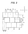
- FIG. 2 is a view illustrating details of the reception antenna 4, and illustrates a specific arrangement of antenna elements constituting the reception antenna 4. Assuming that the horizontal direction and the vertical direction in FIG. 2 are a Y direction and a Z direction, respectively, all the antenna elements constituting the reception antenna 4 are disposed on the same YZ plane in the present embodiment.
- the Y direction and the Z direction will be also referred to as the "horizontal direction” and the “vertical direction”, respectively.
- reference signs 11 to 19 indicated by rectangles represent regions of the respective antenna elements, and one rectangle represents one antenna element.
- Sets of the antenna elements 11, 12, and 13 are arranged at an antenna interval b in the Y direction, and similarly, sets of the antenna elements 14, 15, and 16 and sets of the antenna elements 17, 18, and 19 are also arranged at the antenna interval b in the Y direction.
- the respective sets arranged at different positions in the Z direction are arranged to be offset by an amount a shorter than the interval b in the Y direction.
- b is three times as large as a in the present embodiment.
- FIG. 3 is a view illustrating a positional relationship between the radar device 10 and a detection target T assumed in the present embodiment.
- FIG. 3(a) is a view of the radar device 10 and the detection target T as viewed from the side
- FIG. 3(b) is a view of the radar device 10 and the detection target T as viewed from the side. Note that FIG. 3(b) illustrates two detection targets T1 and T2 for exemplifying an angle.
- the detection target T and the radar device 10 exist approximately apart from each other in an X-axis direction.
- a height h1 from a ground G to the radar device 10 and a height h2 from the ground G to the detection target T are the same.
- an angle ⁇ to the detection target is defined as illustrated in FIG. 3(b) .
- the angle ⁇ is zero if the detection target T exists on an X axis which is the front of the radar device 10.
- the angle ⁇ will be also referred to as an arrival angle ⁇ hereinafter from the meaning of calculating an arrival angle of a radio wave reflected by the detection target.
- the signal processing unit 7 uses signals received by the antenna elements of the reception antenna 4 in the order of installation positions in the Y-axis direction when calculating the arrival angle ⁇ .
- an input vector X in Formula 1 is assumed as reception signals of antenna elements according to the order of the installation positions in the Y-axis direction.
- the antenna elements may be numbered in advance in the order of the installation positions in the Y-axis direction, or the number of the antenna elements may be freely set to rearrange the signals in the order of the installation positions in the Y-axis direction. The latter is adopted in the present embodiment.
- the input vector X is constituted by nine elements in Formula 1 since nine antenna elements are. provided as illustrated in FIG. 2 .
- the number of elements of the input vector X changes according to the number of antenna elements.
- the antenna elements are arranged on the YZ plane, and the installation position of each of the antenna elements is determined by a Y coordinate value and a Z coordinate value in the present embodiment.
- antenna elements having the same Z coordinate value are grouped, and numbers are assigned to the groups in descending order of the Y coordinate values. Specifically, reference signs 11, 12, and 13 are assigned from left to right in the upper part of FIG. 2 , reference signs 14, 15, and 16 are assigned from left to right in the middle part, and reference signs 17, 18, and 19 are assigned from left to right in the lower part.
- the reception signals of these antenna elements are rearranged as follows and used for calculation.
- FIG. 4 is a table illustrating a correspondence between a reception signal used for calculation and a reference sign of an antenna element.
- x1 to x9 illustrated in the column of the reception signal in FIG. 4 are described in Formula 1.
- a peak position of an angle spectrum P BF ( ⁇ ) expressed by Formula 2 is calculated as the arrival angle using the input vector X.
- a superscript H represents a complex conjugate transposition.
- a( ⁇ ) and Rxx are a mode vector and a correlation function of an input vector, respectively, and are expressed by Formula 3 and Formula 4, respectively.
- ⁇ in Formula 3 is a wavelength
- d 1 to d k are intervals in antenna elements in the Y-axis direction.
- a superscript H in Formula 4 represents a complex conjugate transposition
- an operator E[ ] represents an average operation.
- FIG. 5 is a schematic view illustrating a relationship between an arrangement 21 of each antenna element of the reception antenna 4 on a substrate and an arrangement 22 of each virtual antenna element on calculation in the signal processing unit 7.
- Reference signs 11a to 19a indicate center positions of the antenna elements 11 to 19 illustrated in FIG. 2 .
- the respective antenna elements are actually arranged as described above with reference to FIG. 2 .
- the signal processing unit 7 treats positions of the antenna elements indicated by reference signs 11a to 19a as the arrangement order in which the antenna elements are arranged in a line in the horizontal direction as indicated by reference signs 11b to 19b, and calculates the arrival angle ⁇ . That is, an effect of virtually narrowing the antenna interval is produced by rearranging the respective antenna elements so as to minimize the antenna interval in the horizontal direction.
- This rearrangement is executed by the rearrangement processing unit 7a of the signal processing unit 7.
- the rearrangement processing unit 7a may read information illustrated in FIG. 4 from the ROM and perform processing, or may operate a hardware circuit reflecting the information illustrated in FIG. 4 .
- the arrival angle calculation unit 7c can obtain an effect equivalent to the interval a in which the interval between the reception antenna elements is narrower than the actual antenna interval b by using the input rearranged in the above arrangement order. Therefore, an angle is widened at which a phase difference between the reception antennas becomes 2n, that is, phase folding occurs, and a detectable visual field range of the radar can be expanded.
- FIG. 6 is a flowchart illustrating processing of the signal processing unit 7 according to the first embodiment.
- the signal processing unit 7 receives signals from the respective antenna elements of the reception antenna 4 (S11).
- the rearrangement processing unit 7a of the signal processing unit 7 rearranges the arrangement order of the respective reception antenna elements in a predetermined direction based on signal processing (S12).
- the arrival angle calculation unit 7c of the signal processing unit 7 calculates the arrival angle ⁇ in the horizontal direction under the rearranged arrangement order (S13).
- the signal processing unit 7 may calculate a distance and a speed to a detection target before calculating the arrival angle ⁇ .
- the distance and speed can be obtained based on spectrum information of the reception signals by decomposing signals from the respective reception antenna elements of the reception antenna 4 into frequency components.
- the reception signal used for the arrival angle estimation may be a signal processed in the process of calculating the distance or the speed.
- the signal processing unit 7 generates the input vector X by switching the order of the reception signals by software processing.
- the signal processing unit 7 may realize this by a hardware configuration. That is, the rearrangement processing unit 7a is implemented by software in the first embodiment, but may be implemented by hardware.
- the hardware configuration corresponding to the rearrangement processing unit 7a may exist outside the signal processing unit 7.
- Various known means can be used for this hardware configuration. For example, a routing length of a signal line may be devised such that reception signals arrive at the arrival angle calculation unit 7c from antenna elements in the order illustrated in FIG. 4 .
- the signal processing unit 7 generates the vector X by arranging the reception signals of the plurality of antenna elements in the order of the positions of the plurality of antenna elements in the Y direction by a hardware configuration generated in advance. Therefore, it is possible to obtain the same operational effect as those of the first embodiment without using software processing.
- the number of groups arranged in the Z direction correlates with an offset amount for each group.
- an offset amount a may be 1/10 of the antenna interval b regardless of the number of groups.
- an interval between reference signs 11b and 14b and an interval between reference signs 14b and 17b in FIG. 5 are still a, but an interval between reference signs 17b and 12b becomes 8a.
- an arrival angle can be calculated by appropriately setting a value of d in Formula 3.
- a radar device will be described with reference to FIGS. 7 to 10 .
- a difference will mainly be described by applying the same reference signs to the same constituent elements as those of the first embodiment.
- a point not specifically described is the same as that of the first embodiment.
- the present embodiment is different from the first embodiment mainly in terms of handling even a case where positions of the radar device and a detection target in a height direction are not the same.
- h1 and h2 are equal as illustrated in FIG. 3
- the present embodiment also handles a case where h1 and h2 are not equal.
- antenna elements of the reception antennas 4 arranged at different positions in the Z direction regard a phase change derived from a component in the Z direction as a phase change in the horizontal direction, so that it is difficult to calculate the accurate arrival angle ⁇ . Therefore, a phase is corrected according to an arrangement of the antenna elements in the Z direction as will be described hereinafter.
- FIG. 7 is a flowchart illustrating processing of the signal processing unit 7 according to the second embodiment.
- S14 to S16 are added between S11 and S12 of the flowchart illustrated in FIG. 6 in the first embodiment.
- S14 to S16 which are added processes, will be described.
- the signal processing unit 7 acquires phase information of a reception signal of each reception antenna element (S14).
- the signal processing unit 7 calculates phase information in the Z direction orthogonal to the Y direction based on the acquired phase information (S15).
- the signal processing unit 7 removes the phase information in the Z direction from the reception signal.
- FIG. 8 is a view illustrating a definition of an oblique axis.
- two axes 51 and 52 corresponding to arrangements of antenna elements of the reception antenna 4 are introduced as illustrated in FIG. 8 . Since these axes are oblique to the Y axis in the horizontal direction and the Z axis in the vertical direction, the axes are newly defined as oblique axes 51 and 52, and names of the axes are z1 and z2, respectively.
- the oblique axis 51 has a direction of the axis determined from antenna elements 12a, 15a, and 18a, and has an inclination ⁇ 1 with respect to the Z axis in the vertical direction.
- the oblique axis 52 has a direction of the axis determined from antenna elements 13a, 15a, and 17a, and has an inclination ⁇ 2 with respect to the Z axis in the vertical direction.
- unit vectors in the Y axis, the Z axis, the z1 axis, and the z2 axis are expressed as in Formula 5.
- oblique axes are not limited to these, and may be straight lines which pass through two or more antenna elements and are not parallel to the Y axis or the Z axis.
- an axis passing through the antenna elements 13a and 18a may also be set as an oblique axis, instead of the axis 52.
- FIG. 9 is a view illustrating a positional relationship between the radar device 10 and the detection target T according to the second embodiment.
- FIG. 9 is a schematic view illustrating each positional relationship assuming that a center position of the radar device 10 is an origin 30, a coordinate position 31 of an object as the detection target is (x0, y0, z0), and an arrival angle vector 35 of a reflection wave of a radio wave, transmitted from the radar device and reflected by the object to be directed to the radar device, is a vector P.
- the arrival angle vector P can be expressed as in Formula 6 using unit vectors of the x, y, and z axes.
- px, py, and pz in Formula 6 are direction cosines with respect to the X axis, the Y axis, and the Z axis, and for example, the direction cosine pz in the z direction can be expressed by the following Formula 7 using angles ⁇ and ⁇ ' illustrated in FIG. 9 .
- Formula 6 is expressed using the direction cosines with respect to the x, y, and z axes, but may be also expressed using direction cosines with respect to the oblique axis z1 or z2.
- a relational expression with the direction cosines with respect to the y axis and the z axis described above is illustrated in Formula 8.
- pz1' is the direction cosine with respect to the oblique axis z1
- pz2' is the direction cosine with respect to the oblique axis z2.
- These direction cosines are expressed by Formula 9 using the angles ⁇ 1' and ⁇ 2' illustrated in FIG. 9 .
- Formula 10 is derived from Formula 8, the direction cosine pz is obtained by substituting known ⁇ 1 and ⁇ 2 into Formula 10 if the direction cosines pz1' and pz2' are obtained, and an azimuth angle ⁇ in the vertical direction is obtained using Formula 7.
- the direction cosine pz1' is obtained by substituting a wavelength ⁇ if a phase difference ⁇ 1 in a distance difference ⁇ z1 on the axis 51 is obtained as illustrated in Formula 11.
- the phase difference ⁇ 1 can be obtained using, for example, a monopulse method which is a conventional technique if reception signals from two antenna elements on the axis 51 are used. The same applies to the direction cosine pz2'.
- ⁇ z is a shift amount of a position of an antenna element in the Z direction.
- the shift amount ⁇ z of the position of the antenna element in the Z direction between the antenna element 12a and the antenna element 15a is "b".
- the arrival angle can be correctly obtained by correcting a phase of a reception signal of each antenna element based on the phase difference ⁇ z even when the respective antenna elements are arranged in a line in the horizontal direction and the process of calculating the arrival angle in the horizontal direction is performed.
- FIG. 10 is a conceptual view illustrating correction of the phase difference ⁇ z, which corresponds to a case where antenna elements are arranged as illustrated in FIGS. 2 and 5 .
- the antenna elements 14b, 15b, and 16b are used as a reference, and phase calculation illustrated in FIG. 10 is performed on reception signals from the remaining antenna elements by a phase difference correction unit 7b in the signal processing unit 7 as the phase in the vertical direction, and then, the arrival angle is calculated by the arrival angle calculation unit 7c.
- the signal processing unit 7 calculates a phase difference based on a difference in arrangement positions of the plurality of antenna elements in any of the Z direction, a z1 direction, and a z2 direction, and corrects the reception signal using the phase difference. Therefore, the arrival angle can be accurately calculated even when the detection target and the radar device 10 have different heights and do not exist in the same XY plane.
- a radar device will be described with reference to FIGS. 11 to 13 .
- a difference will mainly be described by applying the same reference signs to the same constituent elements as those of the first embodiment.
- a point not specifically described is the same as that of the first embodiment.
- the present embodiment is different from the first and second embodiments mainly in terms of shapes and an arrangement of antenna elements.
- the antenna element has a substantially square shape, and the antenna elements having the same Z coordinate are arranged in contact with each other in the Y direction.
- the arrangement may be changed as in the present embodiment.
- a calculation method of * * in the present embodiment is similar to that in the first and second embodiments. A reason why the calculation method is the same although the arrangement of the antenna elements is different from those of the first and second embodiments will be described later.
- FIG. 11 is a view illustrating the arrangement of the antenna elements according to the third embodiment.
- Reference signs 101 to 109 indicated by rectangles represent regions of the respective antenna elements, and one rectangle represents one antenna element.
- Sets of the antenna elements 101, 102, and 103 are arranged at an antenna interval b in the horizontal direction.
- sets of antenna elements 104, 105, and 106 and sets of antenna elements 107, 108, and 109 are also arranged at the antenna interval b in the horizontal direction.
- the sets arranged at different positions in the vertical direction - are arranged to be offset not only in the horizontal direction but also in the vertical direction. Note that an offset amount in the vertical direction is c.
- FIG. 12 is a schematic view illustrating a relationship between an arrangement 201 of each antenna element of the reception antenna 4 on a substrate and an arrangement 202 of each antenna element in the signal processing unit 7.
- Reference signs 101a to 109a indicate center positions of the antenna elements 101 to 109 illustrated in FIG. 11 .
- the respective antenna elements are actually arranged as described above with reference to FIG. 11 .
- the signal processing unit 7 treats positions of the antenna elements indicated by reference signs 101a to 109a as the arrangement order in which the antenna elements are arranged in a line in the horizontal direction as indicated by reference signs 101b to 109b, and calculates an arrival angle.
- the reception antenna interval in the horizontal direction becomes an interval b/3, which is narrower than the actual antenna interval b, and an angle is widened at which a phase difference between reception antennas becomes 2n, that is, phase folding occurs, and a detectable visual field range of the radar can be widened.
- the signal processing unit 7 may perform processing similar to the content described in the second embodiment, for example, after performing such rearrangement.
- an arrival angle in a predetermined direction can be correctly calculated by introducing the two oblique, axes 51 and 52 corresponding to the arrangement of the antenna elements of the reception antenna 4 and performing similar phase correction processing even when an arrival direction has a component in the Z direction orthogonal to the Y direction.
- the offset amounts of the respective sets of the antenna elements are not limited to the same value in the present embodiment as illustrated in FIG. 11 , and, for example, different offset amounts may be set for the respective sets.
- the antenna intervals in the horizontal direction are not limited to the same value, and may be unequal intervals.
- the number of antenna elements is not limited to nine elements illustrated in FIG. 11 . These values may be freely designed within a scope not departing from the content of the present embodiment.
- the detectable visual field range of the radar can be expanded similarly to the first and second embodiments although the arrangement of the antenna elements is different between FIGS. 2 and 11 .
- a radar device will be described with reference to FIG. 14 .
- a difference will mainly be described by applying the same reference signs to the same constituent elements as those of the first embodiment.
- a point not specifically described is the same as that of the first embodiment.
- the present embodiment is different from the first embodiment mainly in terms of using a virtual antenna.
- the antenna elements of the reception antenna 4 are all real antennas.
- a combination with a virtual antenna generated by multi-input multi-output (MIMO) may be provided.
- Components of the radar device in the present embodiment are similar to those illustrated in FIG. 1 , but some elements of the respective antenna elements of the reception antenna 4 are configured using the virtual antennas by MIMO in the present embodiment.
- FIG. 14(a) is a schematic view illustrating an arrangement of the antenna elements 101, 102, and 103 of the reception antenna 4 and antenna elements 301, 302, and 303 of the transmission antenna 3 in the present embodiment.
- virtual antennas 104 to 109 are generated as illustrated in FIG. 14(b) .
- an antenna configuration is equivalent to the antenna configuration described in the third embodiment, and the same effects as those of the third embodiment can be obtained.
- Some of the plurality of antenna elements are virtual antennas generated by multi-input multi-output processing. Therefore, the number of actual antennas of the reception antenna 4 can be reduced, and thus, it is possible to streamline the radar device.
- a radar device will be described with reference to FIG. 15 .
- a difference will mainly be described by applying the same reference signs to the same constituent elements as those of the first embodiment.
- a point not specifically described is the same as that of the first embodiment.
- the present embodiment is different from the first embodiment mainly in that the number of antenna elements is the minimum.
- FIG. 15 is a view illustrating an arrangement of antenna elements according to the fifth embodiment.
- the number of antenna elements is three, and two antenna elements 11 and 12 have the same Z coordinate.
- the antenna element denoted by reference sign 14 is arranged to be offset by a half of an interval between the antenna elements denoted by reference signs 11 and 12. Therefore, an interval among the three antenna elements in the Y coordinate is b/2.
- the offset amount of each set of antenna elements is not limited to the same value (described as a in FIG. 2 ) as illustrated in FIG. 2 , and for example, the offset amount may be different for each set.
- the antenna intervals in the horizontal direction are not limited to the same value (described as b in FIG. 2 ), and may be unequal intervals.
- the number of antenna elements is not limited to nine, either. These values may be freely designed within a scope not departing from the content of each of the embodiments.
- Some functional configurations illustrated as separate functional blocks may be integrally configured, or a configuration illustrated in one functional block diagram may be divided into two or more functions. In addition, some of the functions of each functional block may be included in another functional block.
Abstract
Description
- The present invention relates to a radar device.
- A millimeter wave, which is a radio wave having a frequency of 30 GHz to 300 GHz, is a frequency band close to light among radio waves, has high straightness and has a property excellent in environmental resistance, specifically, rain, fog, snow, dirt, and the like. A millimeter wave radar to which this property is applie'd as a sensor can measure a distance and a speed to a distant object and an azimuth angle of the object, and is employed as a main sensor of an autonomous vehicle and a leading-edge driving assistance system. Note that a millimeter wave radar used for forward monitoring of a vehicle is required to have a longer detection distance in order to cope with detection of a preceding vehicle and an obstacle on a highway, and the detectable distance has reached about 300 m recently.
- In order to enable such long distance detection, a high-gain transmission antenna and reception antenna are required. Since an antenna gain is proportional to an antenna opening area, a size of an antenna used for a long-range radar is generally larger than that of a mid-range radar. Here, a radar estimates an azimuth angle from a phase difference between reception antennas with respect to signals received by the reception antennas when obtaining the azimuth angle of an object. Thus, when the phase difference becomes 2n, there occurs a problem that it is difficult to uniquely determine the azimuth angle. In order to prevent erroneous detection due to such phase folding, it is conceivable to set an interval between the reception antennas to be narrowed to about a half wavelength such that the phase difference between the reception antennas does not become 2n. However, it is difficult to cope with long distance detection of about 300 m, for example if the antenna gain is narrowed to about the half wavelength since the antenna gain is proportional to the antenna opening area as described above.
-
PTL 1 discloses an apparatus for detecting a direction that includes a plurality of at least one of transmission antennas and reception antennas, transmits and receives a radio wave for each channel formed by combining the transmission and reception antennas, and detects a direction of a target reflecting the radio wave based on a phase difference in reception signals received in the respective channels. The apparatus for detecting a direction includes: a direction calculating device calculating the direction of the target based on the phase difference in the reception signals on the assumption that the phase difference is within a range of -n to +n [rad]; a range determining device determining that the target currently exists in one of a plurality of azimuthal angle ranges respectively corresponding to ranges of the phase difference between (2m - 1)π to (2m + 1)π [rad] (where m is an integer); and a correcting device correcting the direction calculated by the direction calculating device according to a result determined by the range determining device. - PTL 1:
JP 2004-170371 A - In the invention described in
PTL 1, there is room for improvement in the arrangement of antenna elements and a method of using the reception signal. - A radar device according to a first aspect of the present invention includes: an antenna array including a plurality of antenna elements; and a signal processing unit calculating an arrival angle of a reflection wave reflected by a detection target using reception signals of the plurality of antenna elements. The plurality of antenna elements are disposed on a first plane including a first direction. At least one of the plurality of antenna elements is disposed at a position different from the other antenna elements in a second direction orthogonal to the first direction. The signal processing unit arranges the reception signals of the plurality of antenna elements in order of positions of the plurality of antenna elements in the first direction to perform vectorization, and calculates a component of the arrival angle in the first direction.
- According to the present invention, a detectable visual field range of the radar device can be expanded. Other objects, configurations, and effects which have not been described above will become apparent from embodiments to be described hereinafter.
-
- [
FIG. 1] FIG. 1 is a schematic diagram of a radar device. - [
FIG. 2] FIG. 2 is a view illustrating an arrangement of antenna elements according to a first embodiment. - [
FIG. 3] FIG. 3 is a view illustrating a positional relationship between the radar device and a detection target according to the first embodiment. - [
FIG. 4] FIG. 4 is a table illustrating a correspondence between a reception signal used for calculation and a reference sign of the antenna element. - [
FIG. 5] FIG. 5 is a schematic view illustrating a relationship between the arrangement of the antenna elements on a substrate and an arrangement of virtual antenna elements on calculation in a signal processing unit according to the first embodiment. - [
FIG. 6] FIG. 6 is a flowchart illustrating processing of the signal processing unit according to the first embodiment. - [
FIG. 7] FIG. 7 is a flowchart illustrating processing of a signal processing unit according to a second embodiment. - [
FIG. 8] FIG. 8 is a view illustrating a definition of an oblique axis according to the second embodiment. - [
FIG. 9] FIG. 9 is a view illustrating a positional relationship between a radar device and a detection target according to the second'embodiment. - [
FIG. 10] FIG. 10 is a conceptual view illustrating phase difference correction. - [
FIG. 11] FIG. 11 is a view illustrating an arrangement of antenna elements according to a third embodiment. - [
FIG. 12] FIG. 12 is a schematic view illustrating a relationship between the arrangement of the antenna elements on a substrate and an arrangement of virtual antenna elements on calculation in a signal processing unit according to the third embodiment. - [
FIG. 13] FIG. 13 is a view illustrating a definition of an oblique axis according to the third embodiment. - [
FIG. 14] FIG. 14 is a view illustrating an arrangement of antenna elements according to a fourth embodiment. - [
FIG. 15] FIG. 15 is a view illustrating an arrangement of antenna elements according to a fifth embodiment. - Hereinafter, a first embodiment of a radar device will be described with reference to
FIGS. 1 to 6 . -
FIG. 1 is a schematic diagram of aradar device 10. Theradar device 10 includes anoscillator 1, atransmission unit 2, atransmission antenna 3, areception antenna 4, areception unit 5, anAD converter 6, asignal processing unit 7, and acommunication IF unit 8. Theradar device 10 is connected to avehicle control device 9 separately provided in a vehicle. - The
oscillator 1 generates a frequency-modulated modulation signal and supplies the modulation signal to thetransmission unit 2 and thereception unit 5. As theoscillator 1, for example, a phase-locked loop (PLL) including a voltage-controlled oscillator (VCO), a multiplier, and the like is used. When detecting an object in the periphery of the vehicle, thetransmission unit 2 outputs a frequency-modulated transmission signal to thetransmission antenna 3 by performing power amplification of the modulation signal from theoscillator 1. The transmission signal is radiated as a radio wave toward the periphery of the vehicle, for example, the front of the vehicle via thetransmission antenna 3. - In order to detect the object in the periphery of the vehicle, the
reception unit 5 receives a signal obtained as the transmission signal radiated from thetransmission unit 2 via the.transmission antenna 3 is reflected by the object in the periphery of the vehicle and input to thereception antenna 4. Note that thereception antenna 4 includes a plurality of antenna elements as will be described later, thereception antenna 4 can also be referred to as an "antenna array". Then, thereception unit 5 mixes a reception signal with the modulation signal from theoscillator 1 to generate a beat signal according to a frequency difference between these signals, and performs frequency down conversion. The generated beat signal becomes digital data subjected to A/D conversion by theAD converter 6 after an unnecessary frequency has been cut through a band-limiting filter, and thesignal processing unit 7 performs signal processing to calculate a distance to an object in the periphery of the vehicle, a speed, and an arrival angle. Results of the calculation of thesignal processing unit 7 are transmitted to thevehicle control device 9 through thecommunication IF unit 8. - The
signal processing unit 7 includes a CPU that is a central processing unit, a ROM that is a read-only storage device, and a RAM that is a readable/writable storage device. The CPU develops and executes a program stored in the ROM on the RAM to implement a plurality of functions to be described later. However, thesignal processing unit 7 may be realized by a field programmable gate array (FPGA) which is a rewritable logic circuit or an application specific integrated circuit (ASIC), which is an integrated circuit for a specific application, instead of the combination of the CPU, the ROM, and the RAM. In addition, thesignal processing unit 7 may be realized by a combination of different configurations, for example, a combination of a CPU, a ROM, a RAM, and an FPGA, instead of the combination of the CPU, the ROM, and the RAM. - The
signal processing unit 7 includes arearrangement processing unit 7a and an arrivalangle calculation unit 7c as its functions. The respective functions will be described later. Note that the configuration of theradar device 10 described inFIG. 1 is merely an example, and for example, the number of antenna elements of thetransmission antenna 3 and thereception antenna 4 is not limited to that in the configuration illustrated inFIG. 1 . -
FIG. 2 is a view illustrating details of thereception antenna 4, and illustrates a specific arrangement of antenna elements constituting thereception antenna 4. Assuming that the horizontal direction and the vertical direction inFIG. 2 are a Y direction and a Z direction, respectively, all the antenna elements constituting thereception antenna 4 are disposed on the same YZ plane in the present embodiment. - Hereinafter, the Y direction and the Z direction will be also referred to as the "horizontal direction" and the "vertical direction", respectively.
- In
FIG. 2 ,reference signs 11 to 19 indicated by rectangles represent regions of the respective antenna elements, and one rectangle represents one antenna element. Sets of theantenna elements antenna elements antenna elements -
FIG. 3 is a view illustrating a positional relationship between theradar device 10 and a detection target T assumed in the present embodiment.FIG. 3(a) is a view of theradar device 10 and the detection target T as viewed from the side, andFIG. 3(b) is a view of theradar device 10 and the detection target T as viewed from the side. Note thatFIG. 3(b) illustrates two detection targets T1 and T2 for exemplifying an angle. - As illustrated in
FIG. 3(a) , the detection target T and theradar device 10 exist approximately apart from each other in an X-axis direction. In the present embodiment, a height h1 from a ground G to theradar device 10 and a height h2 from the ground G to the detection target T are the same. In addition, an angle θ to the detection target is defined as illustrated inFIG. 3(b) . The angle θ is zero if the detection target T exists on an X axis which is the front of theradar device 10. However, the angle θ will be also referred to as an arrival angle θ hereinafter from the meaning of calculating an arrival angle of a radio wave reflected by the detection target. - It is assumed that the detection target T exists in the same XY plane as the
radar device 10 as described above in the present embodiment, and thesignal processing unit 7 uses signals received by the antenna elements of thereception antenna 4 in the order of installation positions in the Y-axis direction when calculating the arrival angle θ. Specifically, when a beamformer method, for example, is used to calculate the arrival angle θ, an input vector X inFormula 1 is assumed as reception signals of antenna elements according to the order of the installation positions in the Y-axis direction. At this time, the antenna elements may be numbered in advance in the order of the installation positions in the Y-axis direction, or the number of the antenna elements may be freely set to rearrange the signals in the order of the installation positions in the Y-axis direction. The latter is adopted in the present embodiment. - [Formula 1]

- Note that the input vector X is constituted by nine elements in
Formula 1 since nine antenna elements are. provided as illustrated inFIG. 2 . The number of elements of the input vector X changes according to the number of antenna elements. - As illustrated in
FIG. 2 , the antenna elements are arranged on the YZ plane, and the installation position of each of the antenna elements is determined by a Y coordinate value and a Z coordinate value in the present embodiment. In the present embodiment, antenna elements having the same Z coordinate value are grouped, and numbers are assigned to the groups in descending order of the Y coordinate values. Specifically, reference signs 11, 12, and 13 are assigned from left to right in the upper part ofFIG. 2 , reference signs 14, 15, and 16 are assigned from left to right in the middle part, andreference signs -
FIG. 4 is a table illustrating a correspondence between a reception signal used for calculation and a reference sign of an antenna element. Here, x1 to x9 illustrated in the column of the reception signal inFIG. 4 are described inFormula 1. In the beamformer method, a peak position of an angle spectrum PBF(θ) expressed byFormula 2 is calculated as the arrival angle using the input vector X. - [Formula 2]

- In
Formula 2, a superscript H represents a complex conjugate transposition. Here, a(θ) and Rxx are a mode vector and a correlation function of an input vector, respectively, and are expressed byFormula 3 andFormula 4, respectively. - [Formula 3]

- [Formula 4]

- Note that λ in
Formula 3 is a wavelength, and d1 to dk are intervals in antenna elements in the Y-axis direction. For example, when a relationship between a and b inFIG. 2 is 3a = b, d1 to dk are all "a". In addition, a superscript H inFormula 4 represents a complex conjugate transposition, and an operator E[ ] represents an average operation. -
FIG. 5 is a schematic view illustrating a relationship between anarrangement 21 of each antenna element of thereception antenna 4 on a substrate and anarrangement 22 of each virtual antenna element on calculation in thesignal processing unit 7.Reference signs 11a to 19a indicate center positions of theantenna elements 11 to 19 illustrated inFIG. 2 . The respective antenna elements are actually arranged as described above with reference toFIG. 2 . However, thesignal processing unit 7 treats positions of the antenna elements indicated byreference signs 11a to 19a as the arrangement order in which the antenna elements are arranged in a line in the horizontal direction as indicated byreference signs 11b to 19b, and calculates the arrival angle θ. That is, an effect of virtually narrowing the antenna interval is produced by rearranging the respective antenna elements so as to minimize the antenna interval in the horizontal direction. - This rearrangement is executed by the
rearrangement processing unit 7a of thesignal processing unit 7. For example, therearrangement processing unit 7a may read information illustrated inFIG. 4 from the ROM and perform processing, or may operate a hardware circuit reflecting the information illustrated inFIG. 4 . - The arrival
angle calculation unit 7c can obtain an effect equivalent to the interval a in which the interval between the reception antenna elements is narrower than the actual antenna interval b by using the input rearranged in the above arrangement order. Therefore, an angle is widened at which a phase difference between the reception antennas becomes 2n, that is, phase folding occurs, and a detectable visual field range of the radar can be expanded. -
FIG. 6 is a flowchart illustrating processing of thesignal processing unit 7 according to the first embodiment. - First, the
signal processing unit 7 receives signals from the respective antenna elements of the reception antenna 4 (S11). Next, therearrangement processing unit 7a of thesignal processing unit 7 rearranges the arrangement order of the respective reception antenna elements in a predetermined direction based on signal processing (S12). Then, the arrivalangle calculation unit 7c of thesignal processing unit 7 calculates the arrival angle θ in the horizontal direction under the rearranged arrangement order (S13). - Note that the
signal processing unit 7 may calculate a distance and a speed to a detection target before calculating the arrival angle θ. The distance and speed can be obtained based on spectrum information of the reception signals by decomposing signals from the respective reception antenna elements of thereception antenna 4 into frequency components. The reception signal used for the arrival angle estimation may be a signal processed in the process of calculating the distance or the speed. - According to the above-described first embodiment, the following operational effects can be obtained.
- (1) The
radar device 10 includes thereception antenna 4 that is an antenna array having a plurality of antenna elements, and thesignal processing unit 7 that calculates the arrival angle θ of a reflection wave reflected by a detection target using reception signals of the plurality of antenna elements. The plurality of antenna elements are arranged on the YZ plane including the Y-axis direction. The plurality of antenna elements indicated byreference sign 11 to 19 are divided into three groups ofreference signs 11 to 13,reference signs 14 to 16, andreference signs 17 to 19, and the groups have different Z coordinates. Therefore, at least one of the plurality of antenna elements is disposed at a position different from the other antenna elements in the Z direction. Thesignal processing unit 7 arranges the reception signals of the plurality of antenna elements in the order of positions of the plurality of antenna elements in the Y direction to obtain a vector X as represented inFormula 1, and calculates a component of the arrival angle θ in a first direction. Therefore, an effect equivalent to the interval a in which the interval between the reception antenna elements is narrower than the actual antenna interval b can be obtained, the angle at which the phase folding occurs is widened, and the detectable visual field range of theradar device 10 can be widened. - (2) The
signal processing unit 7 rearranges the order of the reception signals of the plurality of antenna elements to perform vectorization based on the correspondence table illustrated inFIG. 4 . Therefore, it is possible to flexibly cope with software processing. - (3) The plurality of antenna elements included in the
reception antenna 4 are classified into three groups. The antenna elements belonging to each of the groups are arranged at the interval b in the Y direction. The three groups have different positions in the Z direction. The three groups are disposed to be offset in the Y direction by a distance obtained by dividing the interval b by three, that is, a distance of "b/3 = a". Therefore, an interval between the Y coordinate values of the antenna elements is minimized and constant as illustrated inFIG. 5 . - In the first embodiment described above, the
signal processing unit 7 generates the input vector X by switching the order of the reception signals by software processing. However, thesignal processing unit 7 may realize this by a hardware configuration. That is, therearrangement processing unit 7a is implemented by software in the first embodiment, but may be implemented by hardware. In addition, the hardware configuration corresponding to therearrangement processing unit 7a may exist outside thesignal processing unit 7. Various known means can be used for this hardware configuration. For example, a routing length of a signal line may be devised such that reception signals arrive at the arrivalangle calculation unit 7c from antenna elements in the order illustrated inFIG. 4 . - According to a first modification, the following operational effects can be obtained.
- (4) The
signal processing unit 7 generates the vector X by arranging the reception signals of the plurality of antenna elements in the order of the positions of the plurality of antenna elements in the Y direction by a hardware configuration generated in advance. Therefore, it is possible to obtain the same operational effect as those of the first embodiment without using software processing. - In the above-described embodiment, the number of groups arranged in the Z direction correlates with an offset amount for each group. However, the both are not necessarily correlated. For example, an offset amount a may be 1/10 of the antenna interval b regardless of the number of groups. In this case, an interval between
reference signs reference signs FIG. 5 are still a, but an interval betweenreference signs Formula 3. - A radar device according to a second embodiment will be described with reference to
FIGS. 7 to 10 . In the following description, a difference will mainly be described by applying the same reference signs to the same constituent elements as those of the first embodiment. A point not specifically described is the same as that of the first embodiment. The present embodiment is different from the first embodiment mainly in terms of handling even a case where positions of the radar device and a detection target in a height direction are not the same. In other words, it is assumed in the first embodiment that h1 and h2 are equal as illustrated inFIG. 3 , but the present embodiment also handles a case where h1 and h2 are not equal. - If only the technique described in the first embodiment is applied to the present embodiment, the following problem occurs. That is, antenna elements of the
reception antennas 4 arranged at different positions in the Z direction regard a phase change derived from a component in the Z direction as a phase change in the horizontal direction, so that it is difficult to calculate the accurate arrival angle θ. Therefore, a phase is corrected according to an arrangement of the antenna elements in the Z direction as will be described hereinafter. -
FIG. 7 is a flowchart illustrating processing of thesignal processing unit 7 according to the second embodiment. - In
FIG. 7 , S14 to S16 are added between S11 and S12 of the flowchart illustrated inFIG. 6 in the first embodiment. Here, S14 to S16, which are added processes, will be described. In S14, thesignal processing unit 7 acquires phase information of a reception signal of each reception antenna element (S14). Next, in S15, thesignal processing unit 7 calculates phase information in the Z direction orthogonal to the Y direction based on the acquired phase information (S15). Then, in S16, thesignal processing unit 7 removes the phase information in the Z direction from the reception signal. - An example of a method for calculating the phase information in the Z direction, which is the process of S15, will be described hereinafter with reference to
FIG. 8 and a formula. -
FIG. 8 is a view illustrating a definition of an oblique axis. In the present embodiment, twoaxes reception antenna 4 are introduced as illustrated inFIG. 8 . Since these axes are oblique to the Y axis in the horizontal direction and the Z axis in the vertical direction, the axes are newly defined as oblique axes 51 and 52, and names of the axes are z1 and z2, respectively. Theoblique axis 51 has a direction of the axis determined fromantenna elements oblique axis 52 has a direction of the axis determined fromantenna elements Formula 5. - [Formula 5]

- Note that the oblique axes are not limited to these, and may be straight lines which pass through two or more antenna elements and are not parallel to the Y axis or the Z axis. For example, an axis passing through the
antenna elements axis 52. -
FIG. 9 is a view illustrating a positional relationship between theradar device 10 and the detection target T according to the second embodiment. Specifically,FIG. 9 is a schematic view illustrating each positional relationship assuming that a center position of theradar device 10 is anorigin 30, a coordinateposition 31 of an object as the detection target is (x0, y0, z0), and anarrival angle vector 35 of a reflection wave of a radio wave, transmitted from the radar device and reflected by the object to be directed to the radar device, is a vector P. The arrival angle vector P can be expressed as inFormula 6 using unit vectors of the x, y, and z axes. - [Formula 6]

- Note that px, py, and pz in
Formula 6 are direction cosines with respect to the X axis, the Y axis, and the Z axis, and for example, the direction cosine pz in the z direction can be expressed by the followingFormula 7 using angles γ and γ' illustrated inFIG. 9 . - . [Formula 7]

- Note that
Formula 6 is expressed using the direction cosines with respect to the x, y, and z axes, but may be also expressed using direction cosines with respect to the oblique axis z1 or z2. A relational expression with the direction cosines with respect to the y axis and the z axis described above is illustrated inFormula 8. - [Formula 8]

- In
Formula 8, pz1' is the direction cosine with respect to the oblique axis z1, and pz2' is the direction cosine with respect to the oblique axis z2. These direction cosines are expressed byFormula 9 using the angles γ1' and γ2' illustrated inFIG. 9 . - [Formula 9]

- Since
Formula 10 is derived fromFormula 8, the direction cosine pz is obtained by substituting known θ1 and θ2 intoFormula 10 if the direction cosines pz1' and pz2' are obtained, and an azimuth angle γ in the vertical direction is obtained usingFormula 7. - [Formula 10]

- Note that the direction cosine pz1' is obtained by substituting a wavelength λ if a phase difference Δϕ1 in a distance difference Δz1 on the
axis 51 is obtained as illustrated inFormula 11. The phase difference Δϕ1 can be obtained using, for example, a monopulse method which is a conventional technique if reception signals from two antenna elements on theaxis 51 are used. The same applies to the direction cosine pz2'. - [Formula 11]

- If the azimuth angle γ is obtained, a phase difference Δϕz in the vertical direction is obtained by
Formula 12. - [Formula 12]

- In
Formula 12, Δz is a shift amount of a position of an antenna element in the Z direction. For example, in the case of the arrangement illustrated inFIG. 2 , the shift amount Δz of the position of the antenna element in the Z direction between theantenna element 12a and theantenna element 15a is "b". The arrival angle can be correctly obtained by correcting a phase of a reception signal of each antenna element based on the phase difference Δϕz even when the respective antenna elements are arranged in a line in the horizontal direction and the process of calculating the arrival angle in the horizontal direction is performed. -
FIG. 10 is a conceptual view illustrating correction of the phase difference Δϕz, which corresponds to a case where antenna elements are arranged as illustrated inFIGS. 2 and5 . For example, theantenna elements FIG. 10 is performed on reception signals from the remaining antenna elements by a phasedifference correction unit 7b in thesignal processing unit 7 as the phase in the vertical direction, and then, the arrival angle is calculated by the arrivalangle calculation unit 7c. - According to the above-described second embodiment, the following operational effects can be obtained.
- (5) The
signal processing unit 7 calculates a phase difference based on a difference in arrangement positions of the plurality of antenna elements in any of the Z direction, a z1 direction, and a z2 direction, and corrects the reception signal using the phase difference. Therefore, the arrival angle can be accurately calculated even when the detection target and theradar device 10 have different heights and do not exist in the same XY plane. - A radar device according to a third embodiment will be described with reference to
FIGS. 11 to 13 . In the following description, a difference will mainly be described by applying the same reference signs to the same constituent elements as those of the first embodiment. A point not specifically described is the same as that of the first embodiment. The present embodiment is different from the first and second embodiments mainly in terms of shapes and an arrangement of antenna elements. - In the first and second embodiments, the antenna element has a substantially square shape, and the antenna elements having the same Z coordinate are arranged in contact with each other in the Y direction. When an antenna element is elongated, however, the arrangement may be changed as in the present embodiment. Meanwhile, a calculation method of * * in the present embodiment is similar to that in the first and second embodiments. A reason why the calculation method is the same although the arrangement of the antenna elements is different from those of the first and second embodiments will be described later.
-
FIG. 11 is a view illustrating the arrangement of the antenna elements according to the third embodiment. Reference signs 101 to 109 indicated by rectangles represent regions of the respective antenna elements, and one rectangle represents one antenna element. Sets of theantenna elements antenna elements antenna elements -
FIG. 12 is a schematic view illustrating a relationship between anarrangement 201 of each antenna element of thereception antenna 4 on a substrate and anarrangement 202 of each antenna element in thesignal processing unit 7.Reference signs 101a to 109a indicate center positions of theantenna elements 101 to 109 illustrated inFIG. 11 . The respective antenna elements are actually arranged as described above with reference toFIG. 11 . However, thesignal processing unit 7 treats positions of the antenna elements indicated byreference signs 101a to 109a as the arrangement order in which the antenna elements are arranged in a line in the horizontal direction as indicated byreference signs 101b to 109b, and calculates an arrival angle. - With the treatment as such an arrangement order, the reception antenna interval in the horizontal direction becomes an interval b/3, which is narrower than the actual antenna interval b, and an angle is widened at which a phase difference between reception antennas becomes 2n, that is, phase folding occurs, and a detectable visual field range of the radar can be widened.
- Note that the
signal processing unit 7 may perform processing similar to the content described in the second embodiment, for example, after performing such rearrangement. For example, as illustrated inFIG. 13(a) or 13(b) , an arrival angle in a predetermined direction can be correctly calculated by introducing the two oblique, axes 51 and 52 corresponding to the arrangement of the antenna elements of thereception antenna 4 and performing similar phase correction processing even when an arrival direction has a component in the Z direction orthogonal to the Y direction. - Note that the offset amounts of the respective sets of the antenna elements are not limited to the same value in the present embodiment as illustrated in
FIG. 11 , and, for example, different offset amounts may be set for the respective sets. Similarly, the antenna intervals in the horizontal direction are not limited to the same value, and may be unequal intervals. In addition, the number of antenna elements is not limited to nine elements illustrated inFIG. 11 . These values may be freely designed within a scope not departing from the content of the present embodiment. - According to the third embodiment described above, the detectable visual field range of the radar can be expanded similarly to the first and second embodiments although the arrangement of the antenna elements is different between
FIGS. 2 and11 . - A radar device according to a fourth embodiment will be described with reference to
FIG. 14 . In the following description, a difference will mainly be described by applying the same reference signs to the same constituent elements as those of the first embodiment. A point not specifically described is the same as that of the first embodiment. The present embodiment is different from the first embodiment mainly in terms of using a virtual antenna. - In the embodiments that have been described so far, the antenna elements of the
reception antenna 4 are all real antennas. In the present embodiment, a combination with a virtual antenna generated by multi-input multi-output (MIMO) may be provided. Components of the radar device in the present embodiment are similar to those illustrated inFIG. 1 , but some elements of the respective antenna elements of thereception antenna 4 are configured using the virtual antennas by MIMO in the present embodiment. -
FIG. 14(a) is a schematic view illustrating an arrangement of theantenna elements reception antenna 4 andantenna elements transmission antenna 3 in the present embodiment. As the transmission from thetransmission antennas virtual antennas 104 to 109 are generated as illustrated inFIG. 14(b) . When such an antenna configuration is generated, an antenna configuration is equivalent to the antenna configuration described in the third embodiment, and the same effects as those of the third embodiment can be obtained. - According to the above-described fourth embodiment, the following operational effects can be obtained.
- (6) Some of the plurality of antenna elements are virtual antennas generated by multi-input multi-output processing. Therefore, the number of actual antennas of the
reception antenna 4 can be reduced, and thus, it is possible to streamline the radar device. - A radar device according to a fifth embodiment will be described with reference to
FIG. 15 . In the following description, a difference will mainly be described by applying the same reference signs to the same constituent elements as those of the first embodiment. A point not specifically described is the same as that of the first embodiment. The present embodiment is different from the first embodiment mainly in that the number of antenna elements is the minimum. -
FIG. 15 is a view illustrating an arrangement of antenna elements according to the fifth embodiment. In the present embodiment, the number of antenna elements is three, and twoantenna elements reference sign 14 is arranged to be offset by a half of an interval between the antenna elements denoted byreference signs - In all the above-described embodiments, the offset amount of each set of antenna elements is not limited to the same value (described as a in
FIG. 2 ) as illustrated inFIG. 2 , and for example, the offset amount may be different for each set. In addition, the antenna intervals in the horizontal direction are not limited to the same value (described as b inFIG. 2 ), and may be unequal intervals. The number of antenna elements is not limited to nine, either. These values may be freely designed within a scope not departing from the content of each of the embodiments. - In the above-described embodiments and modifications, the configurations of functional blocks are merely examples.
- Some functional configurations illustrated as separate functional blocks may be integrally configured, or a configuration illustrated in one functional block diagram may be divided into two or more functions. In addition, some of the functions of each functional block may be included in another functional block.
- Each of the embodiments and modifications described above may be combined. Although various embodiments and modifications have been described as above, the present invention is not limited to these contents. Other aspects that can be considered within the scope of the technical ideas of the present invention are also included in the scope of the present invention.
-
- 2
- transmission unit
- 3
- transmission antenna
- 4
- reception antenna
- 5
- reception unit
- 7
- signal processing unit
- 10
- radar device
Claims (7)
- A radar device comprising:an antenna array including a plurality of antenna elements; anda signal processing unit calculating an arrival angle of a reflection wave reflected by a detection target using reception signals of the plurality of antenna elements,wherein the plurality of antenna elements are disposed on a first plane including a first direction,at least one of the plurality of antenna elements is disposed at a position different from the other antenna elements in a second direction orthogonal to the first direction, andthe signal processing unit arranges the reception signals of the plurality of antenna elements in order of positions of the plurality of antenna elements in the first direction to perform vectorization, and calculates a component of the arrival angle in the first direction.
- The radar device according to claim 1, wherein
the signal processing unit performs the vectorization by rearranging the order of the reception signals of the plurality of antenna elements based on a predetermined correspondence table. - The radar device according to claim 1, wherein
the signal processing unit performs the vectorization by a hardware configuration created in advance. - The radar device according to claim 1, wherein
the signal processing unit calculates a phase difference based on a difference between arrangement positions of the plurality of antenna elements in the second direction, and corrects the reception signal using the phase difference. - The radar device according to claim 1, wherein
the signal processing unit calculates a phase difference based on a difference between arrangement positions of the plurality of antenna elements in a third direction oblique to the first direction on the first plane, and corrects the reception signal using the phase difference. - The radar device according to claim 1, further comprisinga plurality of transmission antenna elements,wherein at least one antenna element included in the plurality of antenna elements is a virtual antenna generated by multi-input multi-output processing.
- The radar device according to claim 1, whereinthe plurality of antenna elements are classified into N (N is a natural number of two or more) groups,the antenna elements belonging to each of the groups are arranged at a first predetermined interval in the first direction,the groups have different positions in the second direction, andthe groups are disposed to be offset by a distance obtained by dividing the first predetermined interval by N in the first direction.
Applications Claiming Priority (2)
| Application Number | Priority Date | Filing Date | Title |
|---|---|---|---|
| JP2019096930 | 2019-05-23 | ||
| PCT/JP2020/019400 WO2020235463A1 (en) | 2019-05-23 | 2020-05-15 | Radar device |
Publications (2)
| Publication Number | Publication Date |
|---|---|
| EP3974860A1 true EP3974860A1 (en) | 2022-03-30 |
| EP3974860A4 EP3974860A4 (en) | 2023-06-07 |
Family
ID=73458906
Family Applications (1)
| Application Number | Title | Priority Date | Filing Date |
|---|---|---|---|
| EP20809978.8A Pending EP3974860A4 (en) | 2019-05-23 | 2020-05-15 | Radar device |
Country Status (3)
| Country | Link |
|---|---|
| EP (1) | EP3974860A4 (en) |
| JP (1) | JP7164714B2 (en) |
| WO (1) | WO2020235463A1 (en) |
Families Citing this family (1)
| Publication number | Priority date | Publication date | Assignee | Title |
|---|---|---|---|---|
| JP2023011202A (en) * | 2021-07-12 | 2023-01-24 | パナソニックIpマネジメント株式会社 | Radar system |
Family Cites Families (8)
| Publication number | Priority date | Publication date | Assignee | Title |
|---|---|---|---|---|
| JP3433417B2 (en) * | 1998-04-02 | 2003-08-04 | トヨタ自動車株式会社 | Radar equipment |
| JP4656124B2 (en) | 2007-11-09 | 2011-03-23 | 株式会社デンソー | Direction detection device |
| DE102008038365A1 (en) * | 2008-07-02 | 2010-01-07 | Adc Automotive Distance Control Systems Gmbh | Vehicle radar system and method for determining a position of at least one object relative to a vehicle |
| DE102010064348A1 (en) | 2010-12-29 | 2012-07-05 | Robert Bosch Gmbh | Radar sensor for motor vehicles |
| US20150253419A1 (en) * | 2014-03-05 | 2015-09-10 | Delphi Technologies, Inc. | Mimo antenna with improved grating lobe characteristics |
| JP2015226291A (en) | 2014-05-29 | 2015-12-14 | トヨタ自動車株式会社 | Electronic scanning type antenna device for vehicle |
| JP2018155678A (en) | 2017-03-21 | 2018-10-04 | 三菱電機株式会社 | Radar device |
| JP7023563B2 (en) | 2017-10-05 | 2022-02-22 | 日本無線株式会社 | Antenna structure for MIMO radar |
-
2020
- 2020-05-15 WO PCT/JP2020/019400 patent/WO2020235463A1/en unknown
- 2020-05-15 JP JP2021520758A patent/JP7164714B2/en active Active
- 2020-05-15 EP EP20809978.8A patent/EP3974860A4/en active Pending
Also Published As
| Publication number | Publication date |
|---|---|
| WO2020235463A1 (en) | 2020-11-26 |
| JPWO2020235463A1 (en) | 2020-11-26 |
| JP7164714B2 (en) | 2022-11-01 |
| EP3974860A4 (en) | 2023-06-07 |
Similar Documents
| Publication | Publication Date | Title |
|---|---|---|
| US7928897B2 (en) | Target detection method for use in radar and radar device using the target detection method | |
| US7898460B2 (en) | Radar target detecting method, and apparatus using the target detecting method | |
| US20220018928A1 (en) | Radar device | |
| EP0947852B1 (en) | Radar apparatus | |
| EP1041398B1 (en) | Radar apparatus using digital beam forming techniques | |
| JP5093298B2 (en) | Direction detection device | |
| US6067048A (en) | Radar apparatus | |
| CN108845295B (en) | Device, method and radar system for determining the position of an object | |
| US9817110B2 (en) | Imaging radar sensor with narrow antenna lobe and wide angle detection range | |
| US11275172B2 (en) | Target detection device | |
| US20110109495A1 (en) | Radar apparatus | |
| KR20180116325A (en) | A radar system comprising an antenna device for transmitting and receiving electromagnetic radiation | |
| JP2000075028A (en) | Mobile dbf radar | |
| CN112567262B (en) | Radar system and vehicle | |
| US9140787B2 (en) | Radar sensor for motor vehicles, especially LCA sensor | |
| JP3821688B2 (en) | Radar equipment | |
| JP2000230974A (en) | Radar apparatus | |
| US20200355788A1 (en) | Radar apparatus | |
| EP1850146B1 (en) | Arriving direction estimator | |
| US11435435B2 (en) | Radar device | |
| EP3974860A1 (en) | Radar device | |
| EP3825716B1 (en) | Radar device and target angle measurement method | |
| JP2010175471A (en) | Radar apparatus | |
| JP2006091029A (en) | Radar device | |
| WO2023218632A1 (en) | Radar device and target detection method |
Legal Events
| Date | Code | Title | Description |
|---|---|---|---|
| STAA | Information on the status of an ep patent application or granted ep patent |
Free format text: STATUS: THE INTERNATIONAL PUBLICATION HAS BEEN MADE |
|
| PUAI | Public reference made under article 153(3) epc to a published international application that has entered the european phase |
Free format text: ORIGINAL CODE: 0009012 |
|
| STAA | Information on the status of an ep patent application or granted ep patent |
Free format text: STATUS: REQUEST FOR EXAMINATION WAS MADE |
|
| 17P | Request for examination filed |
Effective date: 20211223 |
|
| AK | Designated contracting states |
Kind code of ref document: A1 Designated state(s): AL AT BE BG CH CY CZ DE DK EE ES FI FR GB GR HR HU IE IS IT LI LT LU LV MC MK MT NL NO PL PT RO RS SE SI SK SM TR |
|
| DAV | Request for validation of the european patent (deleted) | ||
| DAX | Request for extension of the european patent (deleted) | ||
| REG | Reference to a national code |
Ref country code: DE Ref legal event code: R079 Free format text: PREVIOUS MAIN CLASS: G01S0007020000 Ipc: G01S0013420000 |
|
| A4 | Supplementary search report drawn up and despatched |
Effective date: 20230510 |
|
| RIC1 | Information provided on ipc code assigned before grant |
Ipc: G01S 13/931 20200101ALN20230503BHEP Ipc: G01S 13/58 20060101ALN20230503BHEP Ipc: G01S 13/44 20060101ALN20230503BHEP Ipc: G01S 13/34 20060101ALN20230503BHEP Ipc: G08G 1/16 20060101ALI20230503BHEP Ipc: G01S 7/03 20060101ALI20230503BHEP Ipc: G01S 13/42 20060101AFI20230503BHEP |