EP3974816A1 - Inspection apparatus, inspection system, inspection method, and carrier means - Google Patents
Inspection apparatus, inspection system, inspection method, and carrier means Download PDFInfo
- Publication number
- EP3974816A1 EP3974816A1 EP21196327.7A EP21196327A EP3974816A1 EP 3974816 A1 EP3974816 A1 EP 3974816A1 EP 21196327 A EP21196327 A EP 21196327A EP 3974816 A1 EP3974816 A1 EP 3974816A1
- Authority
- EP
- European Patent Office
- Prior art keywords
- inspection target
- inspection
- image data
- pattern image
- light
- Prior art date
- Legal status (The legal status is an assumption and is not a legal conclusion. Google has not performed a legal analysis and makes no representation as to the accuracy of the status listed.)
- Withdrawn
Links
- 238000007689 inspection Methods 0.000 title claims abstract description 244
- 238000000034 method Methods 0.000 title claims description 8
- 238000003384 imaging method Methods 0.000 claims abstract description 30
- 230000001678 irradiating effect Effects 0.000 claims description 9
- 230000005856 abnormality Effects 0.000 description 18
- 238000010586 diagram Methods 0.000 description 8
- 230000007547 defect Effects 0.000 description 3
- 238000003860 storage Methods 0.000 description 3
- 230000006870 function Effects 0.000 description 2
- 230000003287 optical effect Effects 0.000 description 2
- 230000001052 transient effect Effects 0.000 description 2
- 230000005540 biological transmission Effects 0.000 description 1
- 238000004891 communication Methods 0.000 description 1
- 239000012050 conventional carrier Substances 0.000 description 1
- 230000003247 decreasing effect Effects 0.000 description 1
- 230000001419 dependent effect Effects 0.000 description 1
- 238000001514 detection method Methods 0.000 description 1
- 230000007613 environmental effect Effects 0.000 description 1
- 239000011521 glass Substances 0.000 description 1
- 230000010365 information processing Effects 0.000 description 1
- 238000009434 installation Methods 0.000 description 1
- 238000004519 manufacturing process Methods 0.000 description 1
- 239000000203 mixture Substances 0.000 description 1
- 238000012986 modification Methods 0.000 description 1
- 230000004048 modification Effects 0.000 description 1
- 239000011347 resin Substances 0.000 description 1
- 229920005989 resin Polymers 0.000 description 1
- 239000007787 solid Substances 0.000 description 1
- 238000003466 welding Methods 0.000 description 1
Images



Classifications
-
- G—PHYSICS
- G01—MEASURING; TESTING
- G01N—INVESTIGATING OR ANALYSING MATERIALS BY DETERMINING THEIR CHEMICAL OR PHYSICAL PROPERTIES
- G01N21/00—Investigating or analysing materials by the use of optical means, i.e. using sub-millimetre waves, infrared, visible or ultraviolet light
- G01N21/84—Systems specially adapted for particular applications
- G01N21/88—Investigating the presence of flaws or contamination
- G01N21/8806—Specially adapted optical and illumination features
-
- G—PHYSICS
- G01—MEASURING; TESTING
- G01N—INVESTIGATING OR ANALYSING MATERIALS BY DETERMINING THEIR CHEMICAL OR PHYSICAL PROPERTIES
- G01N21/00—Investigating or analysing materials by the use of optical means, i.e. using sub-millimetre waves, infrared, visible or ultraviolet light
- G01N21/84—Systems specially adapted for particular applications
- G01N21/88—Investigating the presence of flaws or contamination
- G01N21/8851—Scan or image signal processing specially adapted therefor, e.g. for scan signal adjustment, for detecting different kinds of defects, for compensating for structures, markings, edges
-
- G—PHYSICS
- G01—MEASURING; TESTING
- G01N—INVESTIGATING OR ANALYSING MATERIALS BY DETERMINING THEIR CHEMICAL OR PHYSICAL PROPERTIES
- G01N21/00—Investigating or analysing materials by the use of optical means, i.e. using sub-millimetre waves, infrared, visible or ultraviolet light
- G01N21/84—Systems specially adapted for particular applications
- G01N21/88—Investigating the presence of flaws or contamination
- G01N21/8806—Specially adapted optical and illumination features
- G01N2021/8812—Diffuse illumination, e.g. "sky"
-
- G—PHYSICS
- G01—MEASURING; TESTING
- G01N—INVESTIGATING OR ANALYSING MATERIALS BY DETERMINING THEIR CHEMICAL OR PHYSICAL PROPERTIES
- G01N21/00—Investigating or analysing materials by the use of optical means, i.e. using sub-millimetre waves, infrared, visible or ultraviolet light
- G01N21/84—Systems specially adapted for particular applications
- G01N21/88—Investigating the presence of flaws or contamination
- G01N21/8806—Specially adapted optical and illumination features
- G01N2021/8829—Shadow projection or structured background, e.g. for deflectometry
-
- G—PHYSICS
- G01—MEASURING; TESTING
- G01N—INVESTIGATING OR ANALYSING MATERIALS BY DETERMINING THEIR CHEMICAL OR PHYSICAL PROPERTIES
- G01N21/00—Investigating or analysing materials by the use of optical means, i.e. using sub-millimetre waves, infrared, visible or ultraviolet light
- G01N21/84—Systems specially adapted for particular applications
- G01N21/88—Investigating the presence of flaws or contamination
- G01N21/8851—Scan or image signal processing specially adapted therefor, e.g. for scan signal adjustment, for detecting different kinds of defects, for compensating for structures, markings, edges
- G01N2021/8887—Scan or image signal processing specially adapted therefor, e.g. for scan signal adjustment, for detecting different kinds of defects, for compensating for structures, markings, edges based on image processing techniques
Definitions
- Embodiments of the present disclosure relate to an inspection apparatus, an inspection system, an inspection method, and carrier means.
- an inspection apparatus that irradiates an inspection target with light, captures reflected light from a surface of the inspection target as image data, and detects an abnormality of the inspection target based on the image data (for example, Japanese Unexamined Patent Publication No. 2010-505122 ).
- the inspection target is placed on a mount.
- the position of the mount and the position of a light source of the inspection apparatus are fixed in accordance with the type and shape of the inspection target so that the irradiation light is directed to the inspection target on the mount.
- the conventional inspection apparatus it is necessary to adjust the position of the light source and the position of the mount every time the type or shape of the inspection target changes. In some cases, it is necessary to introduce a new inspection apparatus depending on the type or shape of the inspection target. For this reason, it is difficult to use the conventional inspection apparatus to inspect other inspection targets than a particular inspection target determined for each inspection apparatus. Thus, the conventional inspection apparatus has poor versatility.
- the inspection apparatus includes a projector and an imaging device.
- the projector irradiates an inspection target with light according to pattern image data associated with the inspection target, and the pattern image data specifies a pattern of light irradiation of the inspection target.
- the imaging device captures an image of the inspection target being irradiated with the light from the projector and outputs image data of the captured image.
- the inspection system includes the above-described inspection apparatus and a management apparatus connected to the inspection apparatus to communicate with the inspection apparatus.
- the management apparatus includes a pattern image memory that stores the pattern image data, and transmits the pattern image data to the inspection apparatus.
- the method includes irradiating the inspection target with light according to pattern image data associated with the inspection target, capturing an image of the inspection target being irradiated with the light, and outputting image data of the captured image.
- the pattern image data specifies a pattern of light irradiation of the inspection target. Accordingly, the versatility of the inspection apparatus improves.
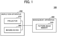
- FIG. 1 is a block diagram illustrating an example of a configuration of an inspection system according to the first embodiment.
- An inspection system 100 includes an inspection apparatus 200 and a management apparatus 300.
- the inspection apparatus 200 and the management apparatus 300 are connected via a wired or wireless network to communicate with each other.
- the inspection apparatus 200 includes a projector 210 and an imaging device 260.
- the projector 210 irradiates an inspection target with light according to pattern image data transmitted from the management apparatus 300.
- the imaging device 260 captures the reflected light from the inspection target as image data.
- the inspection apparatus 200 outputs (transmits) the captured image data to the management apparatus 300.
- the pattern image data according to the present embodiment is image data specifying the position at which the inspection target is irradiated with the light emitted from the projector 210. That is, the pattern image data specifies a pattern of light irradiation of the inspection target.
- the management apparatus 300 may be, for example, a general information processing device including an arithmetic processor, a memory, and a communication interface.
- the management apparatus 300 includes a pattern image memory 310 that stores the pattern image data for each inspection target.
- the pattern image memory 310 may be a part of a storage device (storage area) included in the management apparatus 300, for example.
- the pattern image memory 310 stores the pattern image data generated in advance for each inspection target. In other words, the pattern image memory 310 stores information for identifying an inspection target and pattern image data in association with each other.
- a plurality of pattern image data may be associated with one inspection target.
- the management apparatus 300 transmits, to the inspection apparatus 200, pattern image data corresponding to the inspection target.
- the inspection apparatus 200 irradiates the inspection target with light according to the plurality of pattern image data, and captures the reflected light of he plurality of pattern image data.
- the position of the irradiation light on the inspection target can be easily changed.
- the pattern image memory 310 stores the pattern image data for each inspection target. This enables the inspection apparatus 200 to inspect the inspection target regardless of the type or shape of the inspection target.
- the management apparatus 300 can generate the pattern image data corresponding to the inspection target, to enable the inspection.
- the pattern image data associated with the inspection target may be determined as follows. For example, the pattern image data according to which an inspection target 250 is irradiated is sequentially switched among a plurality of pattern image data stored in the pattern image memory 310. Then, one of the plurality of pattern image data with which the imaging device 260 obtains most appropriate image data is determined as the pattern image data for the inspection target 250.
- the present embodiment is advantageous in, for example, inspecting a small quantity of various kinds of inspection targets.
- the inspection apparatus 200 can inspect various kinds of inspection targets.
- the versatility of the inspection apparatus 200 improves.
- FIG. 2 is a perspective view illustrating an appearance of the inspection apparatus 200.
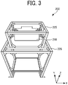
- FIG. 3 is a perspective view illustrating a frame of the inspection apparatus 200.
- FIG. 4 is a cross-sectional view of the inspection apparatus 200 along line A-A in FIG. 2 .
- a Z-axis direction in the drawings is defined as a vertical direction
- a Y-axis direction in the drawings is defined as a front-rear direction
- an X-axis direction in the drawings is defined as a lateral direction.
- the inspection apparatus 200 of the present embodiment includes the projector 210 (see FIG. 3 ), a cover 215, a housing 220, frames 225 and 226 (see FIG. 3 ), and a mount 230 (a jig).
- the projector 210 is fixed to the frame 225 and covered with the cover 215. In this state, the projector 210 is fixed to the upper side of the housing 220. The projector 210 irradiates the inside of the housing 220 with light according to the pattern image data transmitted from the inspection apparatus 200.
- the housing 220 is attached to the frame 226 so as to cover the periphery of the frame 226 and prevents the inspection target from being irradiated with external light.
- the inside of the housing 220 is black.
- the housing 220 enables the inspection apparatus 200 to perform inspection with high reproducibility without being affected by environmental changes depending on the installation location of the inspection apparatus 200.
- the housing 220 has an opening 240 into which the mount 230 is inserted.
- the mount 230 is manufactured in advance for each inspection target 250 in accordance with the type, the shape, and the like of the inspection target 250.
- the mount 230 on which the inspection target 250 is placed is inserted into the opening 240.
- the mount 230 is inserted into the opening 240, but the embodiments of the present disclosure are not limited thereto.
- the opening 240 may have a tunnel shape so as to penetrate the housing 220 in the front-rear direction, and the inspection apparatus 200 may be installed so as to straddle a manufacturing line of the inspection target 250. Further, the mount 230 on which the inspection target 250 is placed may be slid in the front-rear direction.
- the frame 225 is a member for securing the projector 210 and the cover 215.
- a fixing member 270 to which the imaging device 260 is fixed is attached to the frame 226, a fixing member 270 to which the imaging device 260 is fixed is attached.
- the imaging device 260 is fixed to an end of the fixing member 270. Note that the fixing member 270 and the imaging device 260 are disposed not to block the light emitted to the inspection target 250 (workpiece).
- the imaging device 260 captures an image of the inspection target being irradiated with the light from the projector 210, and transmits the captured image data to the management apparatus 300.
- FIGS. 5A to 5D is a diagram illustrating pattern image data according to the first embodiment.
- FIGS. 5A to 5D illustrate pattern images 51, 52, 53, and 54 that are projection images obtained, respectively, by projecting the pattern image data stored in the pattern image memory 310 of the management apparatus 300.
- the management apparatus 300 may generate the pattern image data stored in the pattern image memory 310 in advance, or acquire pattern image data from an external device.
- the pattern image data can be generated in any pattern by any method.
- the pattern image 51 is a projection image obtained by projecting such pattern image data that a rectangular region 51a in a central area is irradiated with the light.
- the inspection target 250 is irradiated with the light according to the pattern image data of the pattern image 51, only a portion of the inspection target 250 corresponding to the rectangular region 51a is irradiated with the light.
- the upper surface of the inspection target 250 is larger than the rectangular region 51a and includes the rectangular region 51a, only a portion of the upper surface of the inspection target 250 corresponding to the rectangular region 51a is irradiated with the light.
- the pattern image 52 in FIG. 5B is a projection image obtained by projecting such pattern image data that a rectangular region 52a wider than the rectangular region 51a in FIG. 5A is irradiated with the light.
- the inspection target 250 is irradiated with the light according to the pattern image data of the pattern image 52, similarly, when the upper surface of the inspection target 250 is larger than the rectangular region 52a and includes the rectangular region 52a, only the upper surface of the inspection target 250 is irradiated with the light.
- the side face of the inspection target 250 is also irradiated with the light from the projector 210.
- the pattern image 53 in FIG. 5C is a projection image obtained by projecting such pattern image data that the pattern image has color shading.
- the pattern image 53 includes a region 53a having a color lighter (a density lower) than that of another part of the pattern image 53.
- the pattern image 53 has black shading, but the color is not limited to black and may be any color expressed by RGB values.
- a portion of the inspection target 250 corresponding to the region 53a is irradiated with light having a wavelength different from that of light with which other regions are irradiated.
- the pattern image 54 in FIG. 5D is a projection image obtained by projecting such pattern image data that a region irradiated with the light alternates with a region not irradiated with the light.
- the pattern image 54 is a projection image obtained by projecting pattern image data representing a striped pattern including the regions irradiated with the light and the regions not irradiated with the light.
- the pattern image 54 includes a pattern image 54A and a pattern image 54B having different striped patterns.
- the region of the inspection target 250 irradiated with the light differs between the case where the inspection target 250 is irradiated with the pattern image data representing the pattern image 54A and the case where the inspection target 250 is irradiated with the pattern image data representing the pattern image 54B.
- the projector 210 by causing the projector 210 to emit light according to the pattern image data specifying the light irradiation position, the light irradiation position on the inspection target 250, the wavelength of the light, and the like can be specified in advance.
- the pattern image data can be generated by the management apparatus 300. Therefore, in the present embodiment, generating the pattern image data according to the type or the shape of the inspection target 250 enables the inspection system 100 to specify the light irradiation position, the wavelength of the light, or the like for each inspection target 250.
- the light irradiation position and the wavelength of the light are changed in accordance with the inspection target, and it is not necessary to adjust the position of the mount or the position of the light source for each inspection target.
- the versatility of the inspection apparatus improves.
- the second embodiment is different from the first embodiment in that the inspection apparatus includes a reflector that reflects light inside the housing and a diffuser that diffuses light, both disposed inside the housing of the inspection apparatus. Accordingly, in the description of the second embodiment below, different points from the first embodiment will be described. Components having substantially the same functions and configurations as those in the first embodiment are denoted by the same reference numerals as in the first embodiment, and redundant descriptions are omitted.
- FIG. 6 is a cross-sectional view of an inspection apparatus 200A according to the second embodiment.
- FIG. 7 is a front view illustrating an interior of the housing 220 of the inspection apparatus 200A according to the second embodiment.
- FIG. 8 is a side view illustrating the interior of the housing 220 thereof.
- the inspection apparatus 200A illustrated in FIG. 6 includes reflectors 281 and 282 disposed inside side walls 221 and 222 of the housing 220, respectively.
- the inspection apparatus 200A according to the present embodiment further includes a diffuser 290 that covers the mount 230.
- the inspection apparatus 200A illustrated in FIG. 6 includes the housing 220 inside which the reflectors 281 and 282 and the diffuser 290 are disposed, the positions thereof are not limited thereto. As long as the reflectors 281 and 282 and the diffuser 290 are disposed so as to control the direction of light irradiation between the projector 210 (light source) and the inspection target 250, the positions thereof are not limited. In other words, in the present embodiment, the housing 220 is not a requisite of the inspection apparatus 200A, and the inspection may be performed in a dark room, a space shielded from external light, or the like.
- the reflectors 281 and 282 are secured to the frame 226. In other words, the reflectors 281 and 282 are disposed on the inner faces of the side walls of the housing 220. The reflectors 281 and 282 reflect light emitted from the projector 210 toward the center side of the housing 220.
- the reflectors 281 and 282 according to the present embodiment may be attachable to and detachable from the frame 226.
- the diffuser 290 is made of, for example, a milky white resin.
- the diffuser 290 diffuses the light emitted from the projector 210 to a region corresponding to the shape of the diffuser 290.
- the diffuser 290 may be made of translucent glass or the like.
- the diffuser 290 prevents the projector 210 from being reflected in a captured image of the inspection target 250, for example, in a case where the surface of the inspection target 250 is mirror-finished.
- the diffuser 290 according to the present embodiment may be attachable to and detachable from the frame 226.
- the imaging device 260 is disposed below the diffuser 290. That is, the diffuser 290 is disposed so as to cover the inspection target 250 and the imaging device 260.
- light L2 emitted from the projector 210 is reflected by the reflector 281 and enters the diffuser 290. Then, the light L2 is deflected by the diffuser 290 and is directed to a region R2 of the side surface of the inspection target 250 on the mount 230.
- the pattern image data at this time represents a projection image in which the region corresponding to the light L1 is red and the region corresponding to the light L2 is blue.
- the region R1 of the inspection target 250 is irradiated with red light
- the region R2 is irradiated with blue light.
- the pattern image data at this time represents a projection image in which the region corresponding to the light L1 is black and the region corresponding to the light L2 is white, the region R1 of the inspection target 250 is not irradiated with light, and the region R2 is irradiated with light.
- the reflectors 281 and 282 and the diffuser 290 provided in this manner can irradiate the inspection target 250 with the light from different angles.
- the color and the angle of the light to the inspection target 250 and the light irradiation position can be changed.
- the inspection apparatus 200A may further include a reflection plate 217 disposed, for example, as illustrated in FIG. 8 .
- the reflection plate 217 reflects the light emitted from the projector 210 into the housing 220.
- the reflection plate 217 can prevent the projector 210 from being reflected in the image captured by the imaging device 260.
- the mount 230 can be provided with a fixing member 295.
- the fixing member 295 secures the inspection target 250 at a position facing the imaging device 260.
- the fixing member 295 is, for example, attachable to and detachable from the mount 230, and may be attached to the mount 230 according to the size, shape, or the like of the inspection target 250.
- the diffuser 290 has a trapezoidal shape in the front view as an example.
- the shape of the diffuser 290 is not limited to that illustrated in FIG. 7 .
- the diffuser 290 may have, for example, a hemispherical shape.
- the inspection apparatus 200A includes the reflectors 281 and 282 and the diffuser 290, but the structure of the inspection apparatus 200A is not limited thereto. Alternatively, the inspection apparatus 200A includes, for example, either the reflectors 281 and 282 or the diffuser 290.
- the inspection apparatus 200A may include only the reflectors 281 and 282, or only the diffuser 290.
- FIGS. 9A to 9C-3 are first diagrams illustrating processing of the management apparatus 300.
- FIG. 9A illustrates an inspection target 250a.
- FIGS. 9B-1 and 9B-2 illustrate image data captured by the imaging device 260.
- FIGS. 9C-1 to 9C-3 illustrate results of determination of presence or absence of abnormality.
- the management apparatus 300 determines the presence or absence of abnormality of the inspection target based on the image data transmitted from the imaging device 260 of the inspection apparatus 200.
- the inspection target 250a illustrated in FIG. 9A is resin-plated part and has a gently projecting upper face.
- the inspection target 250a is mirror-finished.
- the inspection target 250a is associated with pattern image data that specifies irradiating the inspection target 250a with a striped pattern of light including irradiation regions and non-irradiation regions, from directly above the inspection target 250a.
- the inspection target 250 is further associated with pattern image data that specifies irradiating the inspection target 250a with the above-described striped pattern of light at an angle inclined with respect to the upper surface of the inspection target 250a.
- two pattern image data are associated with the inspection target 250a.
- the former pattern image data is referred to as first pattern image data
- the latter pattern image data is referred to as second pattern image data.
- FIGS. 9B-1 and 9B-2 respectively illustrate an image 91 and an image 92 of the inspection target 250a captured by the imaging device 260.
- the image 91 is captured by the imaging device 260 from the inspection target 250a being irradiated according to the first pattern image data.
- the image 92 is captured by the imaging device 260 from the inspection target 250a being irradiated according to the second pattern image data.
- the first and second pattern image data in FIGS. 9B-1 and 9B-2 represent the pattern images 54A and 54B illustrated in FIG. 5D , respectively.
- the management apparatus 300 acquires image data respectively representing the image 91 and the image 92 illustrated in FIGS. 9B-1 and 9B-2 from the inspection apparatus 200A, and determines whether there is an abnormality.
- FIG. 9C-1 a flaw was detected in a portion 92a in the image 92.
- a heat map 92HM is generated from the image data representing the image 92, and a portion 92aHM corresponding to the portion 92a is presented on the heat map 92HM.
- FIG. 9C-2 protrusions are detected at portions 91a and 91b of the image 91.
- a heat map 91HM is generated from the image data representing the image 91, and portions 91aHM and 91bHM corresponding to the portions 91a and 91b are presented on the heat map 91HM.
- FIG. 9C-3 a pit (welding defect) is detected in a portion 91c in the image 91.
- a portion 91cHM corresponding to the portion 91c is presented on the heat map 91HM.
- the management apparatus 300 determines the presence or absence of an abnormality in the inspection target 250a based on a plurality of pattern images of the inspection target 250a, and the plurality of pattern images are obtained by irradiation of the inspection target 250a according to a plurality of pattern image data, respectively.
- the protrusions and a pit are detected from the image 91, and the flaw is detected from the image 92.
- the accuracy of detecting an abnormality in the inspection target 250a improves.
- the management apparatus 300 may determine the presence or absence of an abnormality based on, for example, a change in the continuity of pixel values in image data representing the images 91 and 92, respectively.
- the management apparatus 300 may store in advance the image data of the inspection target 250 having determined as being fee of abnormality. Then, the management apparatus 300 detects the presence or absence of abnormality by comparing the image acquired from the inspection apparatus 200A with the image stored in advance.
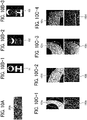
- FIGS. 10A to 10C-4 are second diagrams illustrating the operation of the management apparatus 300.
- FIG. 10A illustrates an inspection target 250b.
- FIGS. 10B-1, 10B-2, and 10B-3 illustrate image data captured by the imaging device 260.
- FIGS. 10C-1, 10C-2, 10C-3, and 10C-4 illustrate results of determination of presence or absence of abnormality.
- the inspection target 250b illustrated in FIG. 10A is a resin-plated plate having a mirror-finished upper face.
- the inspection target 250b is slightly curved and has fine streaks in the longitudinal direction thereof.
- the inspection target 250b is associated with the pattern image data that specifies irradiating the upper face of the inspection target 250b with direct light from the projector 210.
- the inspection target 250b is associated with pattern image data that specifies irradiating the inspection target 250b, from directly above, with a striped pattern of light including bright regions and dark regions, and another pattern image data that specifies irradiating the inspection target 250b with a striped pattern in which the bright regions and the dark regions are reversed.
- the inspection target 250b is associated with three pattern image data.
- pattern image data corresponding to an image 101 in FIG. 10B-1 is referred to as first pattern image data
- pattern image data corresponding to an image 102 in FIG. 10B-2 is referred to as second pattern image data
- pattern image data corresponding to an image 103 in FIG. 10B-3 is referred to as third pattern image data.
- the second pattern image data corresponding to FIG. 10B-2 is, for example, pattern image data representing the pattern image 53 in FIG. 5C .
- the third pattern image corresponding to FIG. 10B-3 is, for example, pattern image data representing an image in which the density of the region 53a of the pattern image 53 in FIG. 5C is increased and the densities of the regions on both sides of the region 53a are decreased.
- FIGS. 10B-1, 10B-2, and 10B-3 respectively illustrate the image 101, the image 102, and the image 103 of the inspection target 250b captured by the imaging device 260.
- the image 101 is captured by the imaging device 260 from the inspection target 250b being irradiated according to the first pattern image data.
- the image 102 is captured by the imaging device 260 from the inspection target 250b being irradiated according to the second pattern image data.
- the image 103 is captured by the imaging device 260 from the inspection target 250b being irradiated according to the third pattern image data.
- the management apparatus 300 acquires the image data representing the image 101, the image data representing the image 102, and the image data representing the image 103 from the inspection apparatus 200A, and determines whether there is an abnormality.
- FIGS. 10C-1 to 10C-4 illustrate results of determination of the presence or absence of an abnormality based on image data respectively representing the image 101, the image 102, and the image 103.
- each of partial images 101a, 101b, 101c, and 101d is a part of the image 101.
- each of partial images 102b, 102c, and 102d is a part of an image 102
- a partial image 103a is a part of the image 103.
- FIG. 10C-1 cloudiness (white haze) of the inspection target 250b is detected in the partial image 103a of the image 103.
- cloudiness is not detected in the partial image 101a of the image 101 at the position corresponding to the partial image 103a.
- the management apparatus 300 determines that there is an abnormality.
- FIG. 10C-2 a flaw on the surface of the inspection target 250b is detected in the partial image 102b of the image 102.
- no flaw is detected in the partial image 101b of the image 101 corresponding to the partial image 102b.
- the management apparatus 300 determines that there is an abnormality in the inspection target 250b.
- FIG. 10C-3 a flaw on the surface of the inspection target 250b is detected in the partial image 102c of the image 102.
- no flaw is detected in the partial image 101c of the image 101 corresponding to the partial image 102c.
- the management apparatus 300 determines that there is an abnormality in the inspection target 250b.
- a pinhole on the surface of the inspection target 250b is detected in the partial image 101d of the image 101.
- no pinhole is detected in the partial image 102d of the image 102 at a position corresponding to the partial image 101d.
- the management apparatus 300 determines that there is an abnormality in the inspection target 250b.
- the management apparatus 300 determines that the inspection target 250b has an abnormality when determining that there is an abnormality in at least one of the plurality of image data respectively acquired by irradiation of the inspection target 250b according to the plurality of pattern image data.
- use of a plurality of pattern image data enables detection of a local defect which is generally easily overlooked. Further, in the present embodiment, since a plurality of pattern image data is selectively used, local defects having different characteristics, such as white haze and pinholes, can be detected by a single inspection.
- providing at least one of the reflectors 281 and 282 and the diffuser 290 increases variations of the angle of light with which the inspection target 250 is irradiated.
- providing at least one of the reflectors 281 and 282 and the diffuser 290 enables the inspection apparatus 200A to irradiate the inspection target 250 with light from various angles.
- selective use of the pattern image data dedicated to each inspection target in irradiating the inspection target is advantageous in that the position of the irradiation light on the inspection target 250 and angle of the irradiation light to the inspection target 250 can be easily changed.
- the inspection apparatus 200A according to the present embodiment can inspect various types of inspection targets, and the versatility of the inspection apparatus improves.
- the present invention can be implemented in any convenient form, for example using dedicated hardware, or a mixture of dedicated hardware and software.
- the present invention may be implemented as computer software implemented by one or more networked processing apparatuses.
- the processing apparatuses include any suitably programmed apparatuses such as a general purpose computer, a personal digital assistant, a Wireless Application Protocol (WAP) or third-generation (3G)-compliant mobile telephone, and so on. Since the present invention can be implemented as software, each and every aspect of the present invention thus encompasses computer software implementable on a programmable device.
- the computer software can be provided to the programmable device using any conventional carrier medium (carrier means).
- the carrier medium includes a transient carrier medium such as an electrical, optical, microwave, acoustic or radio frequency signal carrying the computer code.
- transient medium is a Transmission Control Protocol/Internet Protocol (TCP/IP) signal carrying computer code over an IP network, such as the Internet.
- the carrier medium may also include a storage medium for storing processor readable code such as a floppy disk, a hard disk, a compact disc read-only memory (CD-ROM), a magnetic tape device, or a solid state memory device.
Landscapes
- Chemical & Material Sciences (AREA)
- Pathology (AREA)
- Analytical Chemistry (AREA)
- Physics & Mathematics (AREA)
- Health & Medical Sciences (AREA)
- Life Sciences & Earth Sciences (AREA)
- Biochemistry (AREA)
- Immunology (AREA)
- General Physics & Mathematics (AREA)
- General Health & Medical Sciences (AREA)
- Computer Vision & Pattern Recognition (AREA)
- Engineering & Computer Science (AREA)
- Signal Processing (AREA)
- Investigating Materials By The Use Of Optical Means Adapted For Particular Applications (AREA)
Abstract
An inspection apparatus (200) includes a projector (210) and an imaging device (260). The projector (210) irradiates an inspection target with light according to pattern image data associated with the inspection target, and the pattern image data specifies a pattern of light irradiation of the inspection target. The imaging device (260) captures an image of the inspection target being irradiated with the light from the projector (210) and outputs image data of the captured image.
Description
- Embodiments of the present disclosure relate to an inspection apparatus, an inspection system, an inspection method, and carrier means.
- Conventionally, there is known an inspection apparatus that irradiates an inspection target with light, captures reflected light from a surface of the inspection target as image data, and detects an abnormality of the inspection target based on the image data (for example,
Japanese Unexamined Patent Publication No. 2010-505122 - In the conventional inspection apparatus, it is necessary to adjust the position of the light source and the position of the mount every time the type or shape of the inspection target changes. In some cases, it is necessary to introduce a new inspection apparatus depending on the type or shape of the inspection target. For this reason, it is difficult to use the conventional inspection apparatus to inspect other inspection targets than a particular inspection target determined for each inspection apparatus. Thus, the conventional inspection apparatus has poor versatility.
- In view of the foregoing, there is provided an inspection apparatus, an inspection system, and a method for inspecting an inspection target, as described in appended claims. Advantageous embodiments are defined by the dependent claims.
- Advantageously, the inspection apparatus includes a projector and an imaging device. The projector irradiates an inspection target with light according to pattern image data associated with the inspection target, and the pattern image data specifies a pattern of light irradiation of the inspection target. The imaging device captures an image of the inspection target being irradiated with the light from the projector and outputs image data of the captured image.
- Advantageously, the inspection system includes the above-described inspection apparatus and a management apparatus connected to the inspection apparatus to communicate with the inspection apparatus. The management apparatus includes a pattern image memory that stores the pattern image data, and transmits the pattern image data to the inspection apparatus.
- Advantageously, the method includes irradiating the inspection target with light according to pattern image data associated with the inspection target, capturing an image of the inspection target being irradiated with the light, and outputting image data of the captured image. The pattern image data specifies a pattern of light irradiation of the inspection target. Accordingly, the versatility of the inspection apparatus improves.
- A more complete appreciation of the disclosure and many of the attendant advantages and features thereof can be readily obtained and understood from the following detailed description with reference to the accompanying drawings, wherein:
-
FIG. 1 is a block diagram illustrating an example of a configuration of an inspection system according to a first embodiment; -
FIG. 2 is a perspective view illustrating an appearance of the inspection apparatus according to the first embodiment; -
FIG. 3 is a perspective view illustrating a frame of the inspection apparatus illustrated inFIG. 2 ; -
FIG. 4 is a cross-sectional view of the inspection apparatus along line A-A inFIG. 2 ; -
FIGS. 5A to 5D is a diagrams illustrating pattern image data according to the first embodiment; -
FIG. 6 is a cross-sectional view of an inspection apparatus according to a second embodiment; -
FIG. 7 is a front view of an interior of a housing of the inspection apparatus illustrated inFIG. 6 ; -
FIG. 8 is a side view of the interior of the housing illustrated inFIG. 7 ; -
FIGS. 9A to 9C-3 are first diagrams illustrating operation of a management apparatus according to one embodiment of the present disclosure; and -
FIGS. 10A to 10C-4 are second diagrams illustrating operation of the management apparatus according to one embodiment. - The accompanying drawings are intended to depict embodiments of the present invention and should not be interpreted to limit the scope thereof. The accompanying drawings are not to be considered as drawn to scale unless explicitly noted. Also, identical or similar reference numerals designate identical or similar components throughout the several views.
- In describing embodiments illustrated in the drawings, specific terminology is employed for the sake of clarity. However, the disclosure of this specification is not intended to be limited to the specific terminology so selected and it is to be understood that each specific element includes all technical equivalents that have a similar function, operate in a similar manner, and achieve a similar result.
- Referring now to the drawings, embodiments of the present disclosure are described below. As used herein, the singular forms "a," "an," and "the" are intended to include the plural forms as well, unless the context clearly indicates otherwise.
- Descriptions are given of a first embodiment of the present disclosure with reference to the drawings.
FIG. 1 is a block diagram illustrating an example of a configuration of an inspection system according to the first embodiment. - An
inspection system 100 according to the present embodiment includes aninspection apparatus 200 and amanagement apparatus 300. In theinspection system 100, theinspection apparatus 200 and themanagement apparatus 300 are connected via a wired or wireless network to communicate with each other. - The
inspection apparatus 200 according to the present embodiment includes aprojector 210 and animaging device 260. In theinspection apparatus 200, theprojector 210 irradiates an inspection target with light according to pattern image data transmitted from themanagement apparatus 300. Theimaging device 260 captures the reflected light from the inspection target as image data. Theinspection apparatus 200 outputs (transmits) the captured image data to themanagement apparatus 300. The pattern image data according to the present embodiment is image data specifying the position at which the inspection target is irradiated with the light emitted from theprojector 210. That is, the pattern image data specifies a pattern of light irradiation of the inspection target. - The
management apparatus 300 may be, for example, a general information processing device including an arithmetic processor, a memory, and a communication interface. Themanagement apparatus 300 includes apattern image memory 310 that stores the pattern image data for each inspection target. Thepattern image memory 310 may be a part of a storage device (storage area) included in themanagement apparatus 300, for example. - The
pattern image memory 310 stores the pattern image data generated in advance for each inspection target. In other words, thepattern image memory 310 stores information for identifying an inspection target and pattern image data in association with each other. - In the present embodiment, for example, a plurality of pattern image data may be associated with one inspection target. In this case, when the inspection target is identified, the
management apparatus 300 transmits, to theinspection apparatus 200, pattern image data corresponding to the inspection target. - In the present embodiment, as described above, the
inspection apparatus 200 irradiates the inspection target with light according to the plurality of pattern image data, and captures the reflected light of he plurality of pattern image data. Thus, the position of the irradiation light on the inspection target can be easily changed. - Further, in the present embodiment, the
pattern image memory 310 stores the pattern image data for each inspection target. This enables theinspection apparatus 200 to inspect the inspection target regardless of the type or shape of the inspection target. - In the present embodiment, when the pattern image data corresponding to the inspection target is not stored in the
pattern image memory 310, themanagement apparatus 300 can generate the pattern image data corresponding to the inspection target, to enable the inspection. - In addition, the pattern image data associated with the inspection target may be determined as follows. For example, the pattern image data according to which an
inspection target 250 is irradiated is sequentially switched among a plurality of pattern image data stored in thepattern image memory 310. Then, one of the plurality of pattern image data with which theimaging device 260 obtains most appropriate image data is determined as the pattern image data for theinspection target 250. - As described above, the present embodiment is advantageous in, for example, inspecting a small quantity of various kinds of inspection targets. By switching the pattern image data in accordance with the inspection target, the
inspection apparatus 200 can inspect various kinds of inspection targets. Thus, the versatility of theinspection apparatus 200 improves. - A description is given of the
inspection apparatus 200 according to the present embodiment, with reference toFIGS. 2 to 4 .FIG. 2 is a perspective view illustrating an appearance of theinspection apparatus 200.FIG. 3 is a perspective view illustrating a frame of theinspection apparatus 200.FIG. 4 is a cross-sectional view of theinspection apparatus 200 along line A-A inFIG. 2 . In the following description, for the sake of convenience, a Z-axis direction in the drawings is defined as a vertical direction, a Y-axis direction in the drawings is defined as a front-rear direction, and an X-axis direction in the drawings is defined as a lateral direction. - The
inspection apparatus 200 of the present embodiment includes the projector 210 (seeFIG. 3 ), acover 215, ahousing 220, frames 225 and 226 (seeFIG. 3 ), and a mount 230 (a jig). - The
projector 210 is fixed to theframe 225 and covered with thecover 215. In this state, theprojector 210 is fixed to the upper side of thehousing 220. Theprojector 210 irradiates the inside of thehousing 220 with light according to the pattern image data transmitted from theinspection apparatus 200. - The
housing 220 is attached to theframe 226 so as to cover the periphery of theframe 226 and prevents the inspection target from being irradiated with external light. The inside of thehousing 220 is black. In the present embodiment, thehousing 220 enables theinspection apparatus 200 to perform inspection with high reproducibility without being affected by environmental changes depending on the installation location of theinspection apparatus 200. - The
housing 220 has anopening 240 into which themount 230 is inserted. - The
mount 230 is manufactured in advance for eachinspection target 250 in accordance with the type, the shape, and the like of theinspection target 250. Themount 230 on which theinspection target 250 is placed is inserted into theopening 240. - In the example illustrated in
FIG. 2 , themount 230 is inserted into theopening 240, but the embodiments of the present disclosure are not limited thereto. In theinspection apparatus 200 according to the present embodiment, theopening 240 may have a tunnel shape so as to penetrate thehousing 220 in the front-rear direction, and theinspection apparatus 200 may be installed so as to straddle a manufacturing line of theinspection target 250. Further, themount 230 on which theinspection target 250 is placed may be slid in the front-rear direction. - The
frame 225 is a member for securing theprojector 210 and thecover 215. To theframe 226, a fixingmember 270 to which theimaging device 260 is fixed is attached. Theimaging device 260 is fixed to an end of the fixingmember 270. Note that the fixingmember 270 and theimaging device 260 are disposed not to block the light emitted to the inspection target 250 (workpiece). - The
imaging device 260 captures an image of the inspection target being irradiated with the light from theprojector 210, and transmits the captured image data to themanagement apparatus 300. - Next, a description is given of the pattern image data transmitted from the
management apparatus 300 to theprojector 210 according to the present embodiment, with reference toFIGS. 5A to 5D. FIGS. 5A to 5D is a diagram illustrating pattern image data according to the first embodiment. -
FIGS. 5A to 5D illustratepattern images pattern image memory 310 of themanagement apparatus 300. - The
management apparatus 300 may generate the pattern image data stored in thepattern image memory 310 in advance, or acquire pattern image data from an external device. The pattern image data can be generated in any pattern by any method. - The
pattern image 51 is a projection image obtained by projecting such pattern image data that arectangular region 51a in a central area is irradiated with the light. When theinspection target 250 is irradiated with the light according to the pattern image data of thepattern image 51, only a portion of theinspection target 250 corresponding to therectangular region 51a is irradiated with the light. - Therefore, for example, in a case where the upper surface of the
inspection target 250 is larger than therectangular region 51a and includes therectangular region 51a, only a portion of the upper surface of theinspection target 250 corresponding to therectangular region 51a is irradiated with the light. - The
pattern image 52 inFIG. 5B is a projection image obtained by projecting such pattern image data that arectangular region 52a wider than therectangular region 51a inFIG. 5A is irradiated with the light. In a case where theinspection target 250 is irradiated with the light according to the pattern image data of thepattern image 52, similarly, when the upper surface of theinspection target 250 is larger than therectangular region 52a and includes therectangular region 52a, only the upper surface of theinspection target 250 is irradiated with the light. - In addition, for example, in a case where the upper surface of the
inspection target 250 is smaller than therectangular region 52a, the side face of theinspection target 250 is also irradiated with the light from theprojector 210. - The
pattern image 53 inFIG. 5C is a projection image obtained by projecting such pattern image data that the pattern image has color shading. Thepattern image 53 includes aregion 53a having a color lighter (a density lower) than that of another part of thepattern image 53. In the example illustrated inFIG. 5C , thepattern image 53 has black shading, but the color is not limited to black and may be any color expressed by RGB values. - When the
pattern image 53 is projected onto theinspection target 250, a portion of theinspection target 250 corresponding to theregion 53a is irradiated with light having a wavelength different from that of light with which other regions are irradiated. - The
pattern image 54 inFIG. 5D is a projection image obtained by projecting such pattern image data that a region irradiated with the light alternates with a region not irradiated with the light. In other words, thepattern image 54 is a projection image obtained by projecting pattern image data representing a striped pattern including the regions irradiated with the light and the regions not irradiated with the light. Thepattern image 54 includes apattern image 54A and apattern image 54B having different striped patterns. - Therefore, the region of the
inspection target 250 irradiated with the light differs between the case where theinspection target 250 is irradiated with the pattern image data representing thepattern image 54A and the case where theinspection target 250 is irradiated with the pattern image data representing thepattern image 54B. - As described above, in the present embodiment, by causing the
projector 210 to emit light according to the pattern image data specifying the light irradiation position, the light irradiation position on theinspection target 250, the wavelength of the light, and the like can be specified in advance. - In the present embodiment, the pattern image data can be generated by the
management apparatus 300. Therefore, in the present embodiment, generating the pattern image data according to the type or the shape of theinspection target 250 enables theinspection system 100 to specify the light irradiation position, the wavelength of the light, or the like for eachinspection target 250. - In other words, according to the present embodiment, the light irradiation position and the wavelength of the light are changed in accordance with the inspection target, and it is not necessary to adjust the position of the mount or the position of the light source for each inspection target. Thus, the versatility of the inspection apparatus improves.
- A description is given of a second embodiment of the present disclosure with reference to the drawings. The second embodiment is different from the first embodiment in that the inspection apparatus includes a reflector that reflects light inside the housing and a diffuser that diffuses light, both disposed inside the housing of the inspection apparatus. Accordingly, in the description of the second embodiment below, different points from the first embodiment will be described. Components having substantially the same functions and configurations as those in the first embodiment are denoted by the same reference numerals as in the first embodiment, and redundant descriptions are omitted.
-
FIG. 6 is a cross-sectional view of aninspection apparatus 200A according to the second embodiment.FIG. 7 is a front view illustrating an interior of thehousing 220 of theinspection apparatus 200A according to the second embodiment.FIG. 8 is a side view illustrating the interior of thehousing 220 thereof. - The
inspection apparatus 200A illustrated inFIG. 6 includesreflectors side walls housing 220, respectively. Theinspection apparatus 200A according to the present embodiment further includes adiffuser 290 that covers themount 230. - Although the
inspection apparatus 200A illustrated inFIG. 6 includes thehousing 220 inside which thereflectors diffuser 290 are disposed, the positions thereof are not limited thereto. As long as thereflectors diffuser 290 are disposed so as to control the direction of light irradiation between the projector 210 (light source) and theinspection target 250, the positions thereof are not limited. In other words, in the present embodiment, thehousing 220 is not a requisite of theinspection apparatus 200A, and the inspection may be performed in a dark room, a space shielded from external light, or the like. - The
reflectors frame 226. In other words, thereflectors housing 220. Thereflectors projector 210 toward the center side of thehousing 220. Thereflectors frame 226. - The
diffuser 290 is made of, for example, a milky white resin. Thediffuser 290 diffuses the light emitted from theprojector 210 to a region corresponding to the shape of thediffuser 290. Thediffuser 290 may be made of translucent glass or the like. - In addition, the
diffuser 290 prevents theprojector 210 from being reflected in a captured image of theinspection target 250, for example, in a case where the surface of theinspection target 250 is mirror-finished. Thediffuser 290 according to the present embodiment may be attachable to and detachable from theframe 226. In the present embodiment, theimaging device 260 is disposed below thediffuser 290. That is, thediffuser 290 is disposed so as to cover theinspection target 250 and theimaging device 260. - A description is given below of an optical path of light emitted from the
projector 210 in a case where thereflector 281 and thediffuser 290 are provided, with reference toFIG. 7 . - In
FIG. 7 , light L1 emitted from theprojector 210 is reflected by thereflector 281 and enters thediffuser 290. Then, the light L1 is deflected by thediffuser 290 and directed to a region R1 of the upper surface of theinspection target 250 on themount 230. - In
FIG. 7 , light L2 emitted from theprojector 210 is reflected by thereflector 281 and enters thediffuser 290. Then, the light L2 is deflected by thediffuser 290 and is directed to a region R2 of the side surface of theinspection target 250 on themount 230. - For example, it is assumed that the pattern image data at this time represents a projection image in which the region corresponding to the light L1 is red and the region corresponding to the light L2 is blue. In such a case, the region R1 of the
inspection target 250 is irradiated with red light, and the region R2 is irradiated with blue light. - In another case where the pattern image data at this time represents a projection image in which the region corresponding to the light L1 is black and the region corresponding to the light L2 is white, the region R1 of the
inspection target 250 is not irradiated with light, and the region R2 is irradiated with light. - In the present embodiment, the
reflectors diffuser 290 provided in this manner can irradiate theinspection target 250 with the light from different angles. - Further, in the present embodiment, by switching the pattern image data, the color and the angle of the light to the
inspection target 250 and the light irradiation position can be changed. - In the present embodiment, the
inspection apparatus 200A may further include areflection plate 217 disposed, for example, as illustrated inFIG. 8 . Thereflection plate 217 reflects the light emitted from theprojector 210 into thehousing 220. As described above, for example, even when thediffuser 290 is not provided and the upper surface of theinspection target 250 is mirror-finished, thereflection plate 217 can prevent theprojector 210 from being reflected in the image captured by theimaging device 260. - Further, as illustrated in
FIG. 8 , in theinspection apparatus 200A of the present embodiment, themount 230 can be provided with a fixingmember 295. The fixingmember 295 secures theinspection target 250 at a position facing theimaging device 260. The fixingmember 295 is, for example, attachable to and detachable from themount 230, and may be attached to themount 230 according to the size, shape, or the like of theinspection target 250. - In the present embodiment, as illustrated in
FIG. 7 , thediffuser 290 has a trapezoidal shape in the front view as an example. The shape of thediffuser 290 is not limited to that illustrated inFIG. 7 . Thediffuser 290 may have, for example, a hemispherical shape. - The
inspection apparatus 200A according to the present embodiment includes thereflectors diffuser 290, but the structure of theinspection apparatus 200A is not limited thereto. Alternatively, theinspection apparatus 200A includes, for example, either thereflectors diffuser 290. - To be specific, the
inspection apparatus 200A may include only thereflectors diffuser 290. - Next, a description is given below of operation performed by the
management apparatus 300 according to the present embodiment, with reference toFIGS. 9A to 10C-4. FIGS. 9A to 9C-3 are first diagrams illustrating processing of themanagement apparatus 300.FIG. 9A illustrates aninspection target 250a.FIGS. 9B-1 and 9B-2 illustrate image data captured by theimaging device 260.FIGS. 9C-1 to 9C-3 illustrate results of determination of presence or absence of abnormality. - The
management apparatus 300 determines the presence or absence of abnormality of the inspection target based on the image data transmitted from theimaging device 260 of theinspection apparatus 200. - The
inspection target 250a illustrated inFIG. 9A is resin-plated part and has a gently projecting upper face. Theinspection target 250a is mirror-finished. - In the example illustrated in
FIGS. 9A to 9C-3 , theinspection target 250a is associated with pattern image data that specifies irradiating theinspection target 250a with a striped pattern of light including irradiation regions and non-irradiation regions, from directly above theinspection target 250a. Theinspection target 250 is further associated with pattern image data that specifies irradiating theinspection target 250a with the above-described striped pattern of light at an angle inclined with respect to the upper surface of theinspection target 250a. - Therefore, in the example illustrated in
FIGS. 9A to 9C-3 , two pattern image data are associated with theinspection target 250a. In the following description, the former pattern image data is referred to as first pattern image data, and the latter pattern image data is referred to as second pattern image data. -
FIGS. 9B-1 and 9B-2 respectively illustrate animage 91 and animage 92 of theinspection target 250a captured by theimaging device 260. Theimage 91 is captured by theimaging device 260 from theinspection target 250a being irradiated according to the first pattern image data. Theimage 92 is captured by theimaging device 260 from theinspection target 250a being irradiated according to the second pattern image data. - Specifically, the first and second pattern image data in
FIGS. 9B-1 and 9B-2 represent thepattern images FIG. 5D , respectively. - The
management apparatus 300 according to the present embodiment acquires image data respectively representing theimage 91 and theimage 92 illustrated inFIGS. 9B-1 and 9B-2 from theinspection apparatus 200A, and determines whether there is an abnormality. - In
FIG. 9C-1 , a flaw was detected in aportion 92a in theimage 92. In the example illustrated inFIGS. 9C-1 , a heat map 92HM is generated from the image data representing theimage 92, and a portion 92aHM corresponding to theportion 92a is presented on the heat map 92HM. - In
FIG. 9C-2 , protrusions are detected atportions image 91. In the example illustrated inFIGS. 9C-2 , a heat map 91HM is generated from the image data representing theimage 91, and portions 91aHM and 91bHM corresponding to theportions - In
FIG. 9C-3 , a pit (welding defect) is detected in aportion 91c in theimage 91. In the example illustrated inFIG. 9C-3 , a portion 91cHM corresponding to theportion 91c is presented on the heat map 91HM. - In the present embodiment, as described above, the
management apparatus 300 determines the presence or absence of an abnormality in theinspection target 250a based on a plurality of pattern images of theinspection target 250a, and the plurality of pattern images are obtained by irradiation of theinspection target 250a according to a plurality of pattern image data, respectively. - As a result, the protrusions and a pit are detected from the
image 91, and the flaw is detected from theimage 92. As described above, in the present embodiment, by irradiating oneinspection target 250a according to a plurality of pattern image data, the accuracy of detecting an abnormality in theinspection target 250a improves. - The
management apparatus 300 may determine the presence or absence of an abnormality based on, for example, a change in the continuity of pixel values in image data representing theimages management apparatus 300 may store in advance the image data of theinspection target 250 having determined as being fee of abnormality. Then, themanagement apparatus 300 detects the presence or absence of abnormality by comparing the image acquired from theinspection apparatus 200A with the image stored in advance. -
FIGS. 10A to 10C-4 are second diagrams illustrating the operation of themanagement apparatus 300.FIG. 10A illustrates aninspection target 250b.FIGS. 10B-1, 10B-2, and 10B-3 illustrate image data captured by theimaging device 260.FIGS. 10C-1, 10C-2, 10C-3, and 10C-4 illustrate results of determination of presence or absence of abnormality. - The
inspection target 250b illustrated inFIG. 10A is a resin-plated plate having a mirror-finished upper face. Theinspection target 250b is slightly curved and has fine streaks in the longitudinal direction thereof. - In the example illustrated in
FIG. 10A , theinspection target 250b is associated with the pattern image data that specifies irradiating the upper face of theinspection target 250b with direct light from theprojector 210. - The
inspection target 250b is associated with pattern image data that specifies irradiating theinspection target 250b, from directly above, with a striped pattern of light including bright regions and dark regions, and another pattern image data that specifies irradiating theinspection target 250b with a striped pattern in which the bright regions and the dark regions are reversed. - In the example illustrated in 10A to 10C-4, the
inspection target 250b is associated with three pattern image data. In the following description, pattern image data corresponding to animage 101 inFIG. 10B-1 is referred to as first pattern image data, pattern image data corresponding to animage 102 inFIG. 10B-2 is referred to as second pattern image data, and pattern image data corresponding to animage 103 inFIG. 10B-3 is referred to as third pattern image data. - The second pattern image data corresponding to
FIG. 10B-2 is, for example, pattern image data representing thepattern image 53 inFIG. 5C . The third pattern image corresponding toFIG. 10B-3 is, for example, pattern image data representing an image in which the density of theregion 53a of thepattern image 53 inFIG. 5C is increased and the densities of the regions on both sides of theregion 53a are decreased. -
FIGS. 10B-1, 10B-2, and 10B-3 respectively illustrate theimage 101, theimage 102, and theimage 103 of theinspection target 250b captured by theimaging device 260. Theimage 101 is captured by theimaging device 260 from theinspection target 250b being irradiated according to the first pattern image data. Theimage 102 is captured by theimaging device 260 from theinspection target 250b being irradiated according to the second pattern image data. Theimage 103 is captured by theimaging device 260 from theinspection target 250b being irradiated according to the third pattern image data. - The
management apparatus 300 according to the present embodiment acquires the image data representing theimage 101, the image data representing theimage 102, and the image data representing theimage 103 from theinspection apparatus 200A, and determines whether there is an abnormality. -
FIGS. 10C-1 to 10C-4 illustrate results of determination of the presence or absence of an abnormality based on image data respectively representing theimage 101, theimage 102, and theimage 103. InFIG. 10C-1 to 10C-4 , each ofpartial images image 101. InFIG. 10C-1 to 10C-4 , each ofpartial images image 102, and apartial image 103a is a part of theimage 103. - In
FIG. 10C-1 , cloudiness (white haze) of theinspection target 250b is detected in thepartial image 103a of theimage 103. By contrast, cloudiness is not detected in thepartial image 101a of theimage 101 at the position corresponding to thepartial image 103a. In this case, themanagement apparatus 300 determines that there is an abnormality. - In
FIG. 10C-2 , a flaw on the surface of theinspection target 250b is detected in thepartial image 102b of theimage 102. By contrast, no flaw is detected in thepartial image 101b of theimage 101 corresponding to thepartial image 102b. Also, in this case, themanagement apparatus 300 determines that there is an abnormality in theinspection target 250b. - In
FIG. 10C-3 , a flaw on the surface of theinspection target 250b is detected in thepartial image 102c of theimage 102. By contrast, no flaw is detected in thepartial image 101c of theimage 101 corresponding to thepartial image 102c. Also, in this case, themanagement apparatus 300 determines that there is an abnormality in theinspection target 250b. - In
FIG. 10C-4 , a pinhole on the surface of theinspection target 250b is detected in thepartial image 101d of theimage 101. By contrast, no pinhole is detected in thepartial image 102d of theimage 102 at a position corresponding to thepartial image 101d. Also, in this case, themanagement apparatus 300 determines that there is an abnormality in theinspection target 250b. - As described above, in the present embodiment, the
management apparatus 300 determines that theinspection target 250b has an abnormality when determining that there is an abnormality in at least one of the plurality of image data respectively acquired by irradiation of theinspection target 250b according to the plurality of pattern image data. - In the present embodiment, as described above, use of a plurality of pattern image data enables detection of a local defect which is generally easily overlooked. Further, in the present embodiment, since a plurality of pattern image data is selectively used, local defects having different characteristics, such as white haze and pinholes, can be detected by a single inspection.
- As described above, in the present embodiment, providing at least one of the
reflectors diffuser 290 increases variations of the angle of light with which theinspection target 250 is irradiated. In other words, in the present embodiment, providing at least one of thereflectors diffuser 290 enables theinspection apparatus 200A to irradiate theinspection target 250 with light from various angles. - In addition, in the present embodiment, selective use of the pattern image data dedicated to each inspection target in irradiating the inspection target is advantageous in that the position of the irradiation light on the
inspection target 250 and angle of the irradiation light to theinspection target 250 can be easily changed. - Therefore, according to the present embodiment, when the type or the shape of the inspection target is changed, the inspection can be performed only by switching the pattern image data. That is, the
inspection apparatus 200A according to the present embodiment can inspect various types of inspection targets, and the versatility of the inspection apparatus improves. - In the above-described embodiment, the inspection apparatus includes a single projector, but the number of projectors is not limited to one. The inspection apparatus may include a plurality of projectors. In this case, an image based on the pattern image data may be projected into the space inside the housing using a plurality of projectors.
- Aspects of the present disclosure are described based on the above-described embodiments, but the present disclosure are not limited to the elements of the above-described embodiments. The elements of the above-described embodiments can be modified without departing from the gist of the present disclosure, and can be appropriately determined according to the application form. Thus, numerous additional modifications and variations are possible in light of the above teachings. For example, elements and/or features of different illustrative embodiments may be combined with each other and/or substituted for each other within the scope of the present invention.
- Any one of the above-described operations may be performed in various other ways, for example, in an order different from the one described above.
- The present invention can be implemented in any convenient form, for example using dedicated hardware, or a mixture of dedicated hardware and software. The present invention may be implemented as computer software implemented by one or more networked processing apparatuses. The processing apparatuses include any suitably programmed apparatuses such as a general purpose computer, a personal digital assistant, a Wireless Application Protocol (WAP) or third-generation (3G)-compliant mobile telephone, and so on. Since the present invention can be implemented as software, each and every aspect of the present invention thus encompasses computer software implementable on a programmable device. The computer software can be provided to the programmable device using any conventional carrier medium (carrier means). The carrier medium includes a transient carrier medium such as an electrical, optical, microwave, acoustic or radio frequency signal carrying the computer code. An example of such a transient medium is a Transmission Control Protocol/Internet Protocol (TCP/IP) signal carrying computer code over an IP network, such as the Internet. The carrier medium may also include a storage medium for storing processor readable code such as a floppy disk, a hard disk, a compact disc read-only memory (CD-ROM), a magnetic tape device, or a solid state memory device.
Claims (9)
- An inspection apparatus (200) comprising:a projector (210) configured to irradiate an inspection target with light according to pattern image data associated with the inspection target, the pattern image data specifying a pattern of light irradiation of the inspection target; andan imaging device (260) configured to capture an image of the inspection target being irradiated with the light from the projector (210) and output image data of the captured image.
- The inspection apparatus (200) according to claim 1, further comprising a reflector (281; 282) configured to reflect the light from the projector (210) to the inspection target.
- The inspection apparatus (200) according to claim 1 or 2, further comprising a diffuser (290) disposed to cover the inspection target and the imaging device (260),
wherein the diffuser (290) is configured to diffuse the light from the projector (210). - The inspection apparatus (200) according to claim 2, further comprising a housing (220) configured to cover the inspection target and the imaging device (260),
wherein the reflector (281; 282) is disposed on an inner face of a side wall (221; 222) of the housing (220), to reflect the light from the projector (210) to a center side of the housing (220). - The inspection apparatus (200) according to claim 3, further comprising a housing (220) configured to cover the inspection target and the imaging device (260),
wherein the diffuser (290) is disposed inside the housing (220), to cover the inspection target and the imaging device (260). - The inspection apparatus (200) according to claim 3 or 5,
wherein the diffuser (290) is translucent. - An inspection system comprising:the inspection apparatus (200) according to any one of claims 1 to 6; anda management apparatus (300) connected to the inspection apparatus (200) to communicate with the inspection apparatus (200), the management apparatus (300) including a pattern image memory (310) that stores the pattern image data,wherein the management apparatus (300) transmits the pattern image data to the inspection apparatus (200).
- A method for inspecting an inspection target, the method comprising:irradiating the inspection target with light according to pattern image data associated with the inspection target, the pattern image data specifying a pattern of light irradiation of the inspection target;capturing an image of the inspection target being irradiated with the light; andoutputting image data of the captured image.
- Carrier means carrying computer readable codes for controlling a computer to carry out the method according to claim 8.
Applications Claiming Priority (1)
| Application Number | Priority Date | Filing Date | Title |
|---|---|---|---|
| JP2020162221A JP2022054938A (en) | 2020-09-28 | 2020-09-28 | Inspection device, inspection system, and inspection method |
Publications (1)
| Publication Number | Publication Date |
|---|---|
| EP3974816A1 true EP3974816A1 (en) | 2022-03-30 |
Family
ID=77739019
Family Applications (1)
| Application Number | Title | Priority Date | Filing Date |
|---|---|---|---|
| EP21196327.7A Withdrawn EP3974816A1 (en) | 2020-09-28 | 2021-09-13 | Inspection apparatus, inspection system, inspection method, and carrier means |
Country Status (4)
| Country | Link |
|---|---|
| US (1) | US20220099587A1 (en) |
| EP (1) | EP3974816A1 (en) |
| JP (1) | JP2022054938A (en) |
| CN (1) | CN114280057A (en) |
Citations (5)
| Publication number | Priority date | Publication date | Assignee | Title |
|---|---|---|---|---|
| WO2008124397A1 (en) * | 2007-04-03 | 2008-10-16 | David Fishbaine | Inspection system and method |
| JP2010505122A (en) | 2006-09-29 | 2010-02-18 | マイクロスキャン システムズ インコーポレイテッド | System and / or device for camera-type inspection |
| KR101269220B1 (en) * | 2012-07-05 | 2013-05-30 | 세반코주식회사 | Apparatus for inspecting tire or wheel |
| WO2019083429A1 (en) * | 2017-10-26 | 2019-05-02 | Ivisys Sweden Ab | System and method for optical inspection of an object |
| US20200205325A1 (en) * | 2017-07-12 | 2020-06-25 | Mycronic AB | Method and system for determining component illumination settings |
Family Cites Families (10)
| Publication number | Priority date | Publication date | Assignee | Title |
|---|---|---|---|---|
| JPS511154A (en) * | 1974-06-24 | 1976-01-07 | Canon Kk | HIKARIBIIMUOSHOSHITA SOKUTEIKENSHUTSUHOHO |
| JPH02167450A (en) * | 1988-07-19 | 1990-06-27 | Texas Instr Inc <Ti> | Hemispherical non-glare lighting apparatus |
| JP2738300B2 (en) * | 1994-06-20 | 1998-04-08 | 白柳式撰果機株式会社 | Indirect illumination type multi-sided photographing device used for camera sorting machine for bulk fruits and vegetables |
| JP6194622B2 (en) * | 2013-04-23 | 2017-09-13 | 株式会社島津製作所 | Illumination device and inspection device |
| JP6938093B2 (en) * | 2017-11-21 | 2021-09-22 | 株式会社マクシスエンジニアリング | A method for inspecting the boundary of an object to be inspected and its inspection device |
| JP6904263B2 (en) * | 2018-01-10 | 2021-07-14 | オムロン株式会社 | Image processing system |
| JP7010057B2 (en) * | 2018-02-26 | 2022-01-26 | オムロン株式会社 | Image processing system and setting method |
| JP7087458B2 (en) * | 2018-03-06 | 2022-06-21 | オムロン株式会社 | Image inspection equipment, image inspection method and image inspection program |
| JP7175214B2 (en) * | 2019-02-13 | 2022-11-18 | リコーインダストリアルソリューションズ株式会社 | inspection equipment |
| JP2020148735A (en) * | 2019-03-15 | 2020-09-17 | パナソニックIpマネジメント株式会社 | Inspection device |
-
2020
- 2020-09-28 JP JP2020162221A patent/JP2022054938A/en active Pending
-
2021
- 2021-09-07 US US17/467,957 patent/US20220099587A1/en not_active Abandoned
- 2021-09-13 EP EP21196327.7A patent/EP3974816A1/en not_active Withdrawn
- 2021-09-16 CN CN202111090026.6A patent/CN114280057A/en not_active Withdrawn
Patent Citations (5)
| Publication number | Priority date | Publication date | Assignee | Title |
|---|---|---|---|---|
| JP2010505122A (en) | 2006-09-29 | 2010-02-18 | マイクロスキャン システムズ インコーポレイテッド | System and / or device for camera-type inspection |
| WO2008124397A1 (en) * | 2007-04-03 | 2008-10-16 | David Fishbaine | Inspection system and method |
| KR101269220B1 (en) * | 2012-07-05 | 2013-05-30 | 세반코주식회사 | Apparatus for inspecting tire or wheel |
| US20200205325A1 (en) * | 2017-07-12 | 2020-06-25 | Mycronic AB | Method and system for determining component illumination settings |
| WO2019083429A1 (en) * | 2017-10-26 | 2019-05-02 | Ivisys Sweden Ab | System and method for optical inspection of an object |
Also Published As
| Publication number | Publication date |
|---|---|
| CN114280057A (en) | 2022-04-05 |
| JP2022054938A (en) | 2022-04-07 |
| US20220099587A1 (en) | 2022-03-31 |
Similar Documents
| Publication | Publication Date | Title |
|---|---|---|
| JP3855756B2 (en) | 3D color shape detection device and 3D scanner | |
| JP2007515640A (en) | Spectrophotometer with digital camera | |
| US20090046300A1 (en) | Device for examining the optical properties of surfaces | |
| CN103563079B (en) | Camera assembly and method of use for extraction of image depth discontinuities | |
| JP5410092B2 (en) | Apparatus and method for inspecting composite structures for inconsistencies | |
| EP3846121B1 (en) | Inspection system, information processing apparatus, and carrier means | |
| EP1980816A1 (en) | Optical measuring machine | |
| CN114450579A (en) | Image processing system, setting method, and program | |
| KR101640555B1 (en) | Camera Test Apparatus | |
| JP5121510B2 (en) | Imaging system, imaging method, program, computer-readable storage medium, and image processing apparatus | |
| JP3935048B2 (en) | Covered wire inspection equipment | |
| US6836561B2 (en) | Method and system for detecting a defect in projected portions of an object having the projected portions formed in the same shape with a predetermined pitch along an arc | |
| US20220099587A1 (en) | Inspection apparatus, inspection system, and inspection method | |
| US5767961A (en) | Apparatus and method for inspecting fluorescent screen | |
| JP2007147506A (en) | Piping inspection system and self-propelled piping inspection device used therefor | |
| CN119534482A (en) | Method and system for detecting defects on workpiece surface | |
| US20230314335A1 (en) | Optical inspection method, non-transitory storage medium storing optical inspection program, processing device, and optical inspection apparatus | |
| JP4151571B2 (en) | In-vehicle obstacle detection device | |
| JP2605191B2 (en) | Inspection method for electronic components | |
| JP4397549B2 (en) | Beam profile verification method | |
| JP5449728B2 (en) | Inspection device | |
| JPH0625713U (en) | Soldering part inspection device | |
| CN115239935B (en) | Jewelry terminal, jewelry detection method, jewelry detection device and readable storage medium | |
| JPH09304029A (en) | Surface shape inspection device | |
| JP2014055845A (en) | Component inspection apparatus and component inspection method |
Legal Events
| Date | Code | Title | Description |
|---|---|---|---|
| PUAI | Public reference made under article 153(3) epc to a published international application that has entered the european phase |
Free format text: ORIGINAL CODE: 0009012 |
|
| STAA | Information on the status of an ep patent application or granted ep patent |
Free format text: STATUS: REQUEST FOR EXAMINATION WAS MADE |
|
| 17P | Request for examination filed |
Effective date: 20210913 |
|
| AK | Designated contracting states |
Kind code of ref document: A1 Designated state(s): AL AT BE BG CH CY CZ DE DK EE ES FI FR GB GR HR HU IE IS IT LI LT LU LV MC MK MT NL NO PL PT RO RS SE SI SK SM TR |
|
| STAA | Information on the status of an ep patent application or granted ep patent |
Free format text: STATUS: THE APPLICATION HAS BEEN WITHDRAWN |
|
| 18W | Application withdrawn |
Effective date: 20230123 |