EP3974784A1 - Mehrphasen-flussmessung - Google Patents
Mehrphasen-flussmessung Download PDFInfo
- Publication number
- EP3974784A1 EP3974784A1 EP20207786.3A EP20207786A EP3974784A1 EP 3974784 A1 EP3974784 A1 EP 3974784A1 EP 20207786 A EP20207786 A EP 20207786A EP 3974784 A1 EP3974784 A1 EP 3974784A1
- Authority
- EP
- European Patent Office
- Prior art keywords
- fluid
- flow
- measure
- measurement section
- measures
- Prior art date
- Legal status (The legal status is an assumption and is not a legal conclusion. Google has not performed a legal analysis and makes no representation as to the accuracy of the status listed.)
- Granted
Links
Images
Classifications
-
- G—PHYSICS
- G01—MEASURING; TESTING
- G01F—MEASURING VOLUME, VOLUME FLOW, MASS FLOW OR LIQUID LEVEL; METERING BY VOLUME
- G01F1/00—Measuring the volume flow or mass flow of fluid or fluent solid material wherein the fluid passes through a meter in a continuous flow
- G01F1/74—Devices for measuring flow of a fluid or flow of a fluent solid material in suspension in another fluid
-
- A—HUMAN NECESSITIES
- A01—AGRICULTURE; FORESTRY; ANIMAL HUSBANDRY; HUNTING; TRAPPING; FISHING
- A01J—MANUFACTURE OF DAIRY PRODUCTS
- A01J5/00—Milking machines or devices
- A01J5/007—Monitoring milking processes; Control or regulation of milking machines
- A01J5/01—Milkmeters; Milk flow sensing devices
-
- G—PHYSICS
- G01—MEASURING; TESTING
- G01F—MEASURING VOLUME, VOLUME FLOW, MASS FLOW OR LIQUID LEVEL; METERING BY VOLUME
- G01F1/00—Measuring the volume flow or mass flow of fluid or fluent solid material wherein the fluid passes through a meter in a continuous flow
- G01F1/704—Measuring the volume flow or mass flow of fluid or fluent solid material wherein the fluid passes through a meter in a continuous flow using marked regions or existing inhomogeneities within the fluid stream, e.g. statistically occurring variations in a fluid parameter
- G01F1/708—Measuring the time taken to traverse a fixed distance
Definitions
- the present invention relates generally to measuring fluid flows. More particularly the invention relates to a device according to the preamble of claim 1 and a method according to the preamble of claim 11. The invention also relates to a computer program according to claim 19 and a computer readable medium according to claim 20.
- Measuring a liquid flow is a relatively straightforward task provided that the flowing medium is homogenous, i.e. if there is only a single substance present in the conduit where the flow is to be measured.
- the flowing medium is non-homogenous, i.e. there is more than one substance present in the conduit.
- the proportions between the different constituents in the flow may vary over time. As a result, it can be rather complicated to determine relevant flow measures. To mention a few examples, such liquid flows are common in milk extraction and transport, and in the oil and gas industry.
- WO 01/29518 discloses a solution for carrying out measurements of a pulsating milk flow in a line.
- the measured medium comprises a gas and a liquid.
- the line has a measuring region in which at least one parameter of the medium is determined during a measurement.
- the measuring region may contain a measuring chamber in which milk remains after a pulse flow. This allows further analysis of the milk, such as color analysis.
- US 5,116,119 reveals a solution for measuring milk flows, wherein the liquid is directed to flow through one or more flow channels, while exposing the liquid to electromagnetic radiation.
- the liquid's transparency to electromagnetic radiation is used to determine a momentary volume of the liquid flowing through each flow channel.
- the momentary velocity of the liquid flowing through the flow channels is also determined, thereby permitting a determination of the momentary flow rate of the liquid flowing through the flow channels.
- EP 1 155 610 describes a quantity meter for determining the quantity of liquid flowing through a line.
- the quantity meter has two electrically conductive elements arranged in the line at a fixed measuring distance from each other.
- the conductive elements are connected to an electronic circuit.
- the diameter of the line is such that when the liquid is flowing there through the volume of the line across the measuring distance is completely filled for some time.
- the quantity of liquid flowing through is determined based on the measured electric conductivity of the liquid therein.
- US 7,155,971 shows a device for determining the volumetric flow rate of milk flowing during a milking process.
- a cross-sectional area of the milk flow is determined at a first measuring point by means of a sensor, which is arranged outside the flowing milk.
- the time required by the milk flow, with the determined cross-sectional area, to go from the first measuring point to a second measuring point provided downstream from the first measuring point is measured.
- the flow speed is then derived from the measured time and the known distance between the first and second measuring points.
- the volumetric flow rate is determined on the basis of the determined cross-sectional area and the flow speed.
- the object of the present invention is to mitigate the above problem, and thus offer an improved means for determining a flow of a first fluid (e.g. a gas) or a flow of a second fluid (e.g. a liquid), or both, in a fluid flow where the first and second fluids are mixed.
- a first fluid e.g. a gas
- a second fluid e.g. a liquid
- the object is achieved by the initially described device, wherein the first measure represents a first type of physical characteristic of the fluid medium flowing through the measurement section, and the second measure represents a second type of physical characteristic of the fluid medium flowing through the measurement section.
- the second type of physical characteristic is here different from the first type of physical characteristic.
- the first measure may represent a speed of the flowing medium
- the second measure represents a filling degree of the measurement section (or a ratio between the amounts of first and second fluids therein).
- alternative physical characteristics are also conceivable, such as representations of distinctive flow patterns in the fluid medium.
- this device is advantageous because it provides straightforward information concerning the flow components of the constituents in a mixed fluid flow, such as the air and/or milk respectively in a milk conduit of a milking installation.
- each of the first and second sensor devices comprises at least one inductive sensor, conductive sensor, differential-pressure sensor, optical sensors and/or acoustic sensor.
- first and second measures represent different types of physical characteristics
- the first and second sensor devices may include the same types of sensor devices.
- the above-mentioned sensor devices are all beneficial because they are unobtrusive, i.e. do not influence the measurements as such.
- the device includes a data storage including a look-up table.
- the look-up table contains representative values of the flow of the first fluid and/or the flow of the second fluid for each of a set of pairs of the first and second measures.
- the processor is configured to derive the first and second measures based on the look-up table, for example by interpolating between, or extrapolating from the data therein. Hence, the design becomes very processing efficient.
- the processor is instead configured to implement an artificial neural network modeling a relationship between a set of pairs of the first and second measures and the flow of the first fluid and/or the flow of the second fluid respectively.
- the first sensor device is configured to register the first measure as a speed of the fluid medium and the second sensor device is configured to measure an electrical conductivity of the fluid in the measurement section. Based thereon, a measure is derived representing an estimated ratio between an amount of the first fluid and an amount of the second in the measurement section.
- the measurement section contains a designated space configured to temporarily store an amount of the fluid medium.
- An electrical conductivity reference measurement is executed with respect to the amount fluid medium stored in this space.
- the second sensor device is configured to register the second measure as a pressure drop over a well-defined conduit segment of the measurement section.
- Such an arrangement is especially suitable for registering relatively high flow rates.
- the second sensor device is configured to analyze the fluid medium in the measurement section during a measurement interval. Based thereon, the second measure is produced to represent a flow pattern of the fluid medium during said measurement interval.
- the flow pattern may be a statistical representation of how the first and second fluids are distributed in the measurement section over time. Namely, for instance, a given ratio between gas and liquid may correspond to many different distributions of gas bubbles in the liquid ranging from one large bubble to a high number of very small bubbles. These differences can be captured in the form of various flow pattern classifications, which, in turn (given a particular flow rate), correspond to different liquid flows and gas flows.
- the device includes a third sensor device which is also arranged in the measurement section.
- the third sensor device is configured to derive a third measure representing an estimated ratio between an amount of the first fluid and an amount of the second fluid in the measurement section based on a measured electrical conductivity of the fluid in the measurement section.
- the second sensor device is configured to register the second measure as a pressure drop over a well-defined conduit segment of the measurement section.
- the processor is configured to derive the flow of the first fluid and the flow of the second fluid based on the first, second and third measures by using the second measure for fluid flow rates above or equal to a threshold flow rate and using the third measure for fluid flow rates below the threshold flow rate.
- the object is achieved by the method described initially, wherein the first measure is registered to represent a first type of physical characteristic of the fluid medium flowing through the measurement section, and the second measure is registered to represent a second type of physical characteristic of the fluid medium flowing through the measurement section, the second type of physical characteristic being different from the first type of physical characteristic.
- the object is achieved by a computer program, which is directly loadable into the memory of a computer, and includes software adapted to implement the method proposed above when said program is run on a computer.
- the object is achieved by a computer readable medium, having a program recorded thereon, where the program is to control a computer to perform the method proposed above when the program is loaded into the computer.
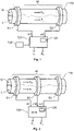
- Figure 1 shows a device according to a first embodiment of the invention.
- the first fluid represents a liquid L
- the second fluid represents a gas G
- a liquid flow F L or a gas flow F G is to be determined in a fluid medium containing a mix of gas G and liquid L.
- the gas G in turn, may contain air and the liquid L, in turn, may contain milk.
- any alternative gas and liquid media are conceivable.
- the invention is applicable to situations wherein the fluid medium contains a mix of different liquid media, e.g. water and oil, as well as other combinations of liquid and gas, such as oil/gas, water/steam, and oil/gas/water.
- the proposed device includes a conduit 110, a first sensor device S1, a second sensor device S2 and a processor 120.
- the conduit 110 for example a milk line, is configured to receive and transport the fluid medium through a measurement section M.
- the first sensor device S1 (here schematically illustrated as a ring around the conduit 110) is arranged in the measurement section M, and configured to register a first measure m1 in respect of the fluid medium.
- the first measure m1 represents a first physical characteristic of the fluid medium in the measurement section M, such as the speed of the fluid medium.
- the first measure m1 may represent a ratio between the amount of gas G and the amount of liquid L present in the measurement section M (where the first sensor device S1 is located), i.e. a filling degree.
- the first measure m1 may otherwise represent a flow pattern of the liquid medium.
- the first sensor device S1 is configured to register the first measure m1 in response to energy fluctuations induced by the fluid medium flowing through the measurement section M.
- the first sensor device S1 is designed to respond to at least one stimulus caused by the fluid medium.
- the first sensor device S1 may include one or more of the following: inductive sensors, conductive sensors, optical sensors and acoustic sensors.
- the second sensor device S2 is likewise configured to respond to at least one stimulus caused by the fluid medium, and may thus include at least one inductive sensor, at least one conductive sensor, at least one optical sensor and/or at least one acoustic sensor.
- a second measure m2 registered by the second sensor device S2 represents a second type of physical characteristic, which is different from the first type of physical characteristic. This means that if for example the first measure m1 represents the speed of the fluid medium, the second measure m2 is a non-speed measure, such as the ratio between the amounts of gas G and liquid L in the measurement section M.
- the second measure m2 may represent the speed of the fluid medium, a ratio between the amount of gas G and the amount of liquid L present in the measurement section M (where the second sensor device S2 is located), a pressure drop over a well-defined conduit segment of the measurement section M, or a flow pattern provided that the first and second measures m1 and m2 are different from one another.
- the second measure m2 reflects a physical characteristic of a type different from that of the first measure m1, the second measure m2 is independent from the first measure m1.
- Each sensor device S1 and S2 may contain two or more sensor elements.
- a conductive sensor configured to register a measure m1/m2 in the form of a volumetric flow rate requires at least two separate sensor elements to determine a travel time across a known distance.
- the measurement section M includes a designated space (e.g. a cavity, groove or other suitable volume) configured to temporarily store an amount of the fluid medium. Repeated electrical conductivity reference measurements can then be executed with respect to the amount of fluid medium in the designated space.
- the measure m1 or m2 may also represent a pressure drop over a well-defined conduit segment of the measurement section M.
- the sensor device in question S1/S2 contains a differential-pressure sensor.
- one of the sensor devices S1 or S2 is configured to analyze the fluid medium in the measurement section M during a measurement interval, say 0.5 to 45 seconds. Based on this analysis, the sensor device is configured to produce a measure m1 or m2 respectively to represent a flow pattern of the fluid medium during the measurement interval.
- the flow pattern describes how the gas and liquid are distributed in the measurement section over time. Namely, the filling degree alone may not provide a sufficiently accurate measure of the liquid-gas distribution in the fluid conduit 110, since a given ratio between gas and liquid may correspond to anything from a liquid amount joined by a single gas bubble to the same liquid amount being fully foamed by microscopic bubbles.
- it is vital that such differences in the gas-liquid distribution are identified.
- different distinctive flow patterns are determined based on averaging and statistical analysis of, for instance the spectral properties of the fluid flow.
- the first sensor device S1 is arranged upstream of the second sensor device S2 in the measurement section M relative to a flow direction of the fluid medium.
- the sensor devices S1 and S2 may equally well be co-located in the measurement section M. The specific design chosen depends on which type(s) of sensor elements that are included in the sensor devices S1 and S2.
- the processor 120 is configured to derive the liquid flow F L and/ or the gas flow F G based on the first and second measures m1 and m2 respectively. This is possible because the first and second measures m1 and m2 are mutually independent and both dependent on the two flow components F G and F L .
- F G F L F 1 m 1 , m 2 F 2 m 1 , m 2
- F1(m1, m2) is a first function of the measures m1 and m2
- F2(m1, m2) is a second function of the measures m1 and m2.
- the proposed device includes a data storage 130 including a look-up table containing representative values of the gas flow F G and/or the liquid flow F L for each of a set of pairs of the first and second measures m1 and m2.
- the look-up table is preferably based on a relatively large number of reference measurements of m1 and m2, where each measurement is correlated with an independent registering of the gas flow F G and the liquid flow F L (i.e. a specific measuring of each separate flow).
- the look-up table may represent a substantial amount of data. Therefore, in some implementations, it may be interesting to trade storage space against processing resources, and thus replace the look-up table with an artificial neural network ANN modeling the relationship between pairs of the first and second measures m1 and m2 and/or the gas flow F G and the liquid flow F L respectively.
- Figure 2 shows such an embodiment of the invention.
- all the reference labels that also occur in Figure 1 designate the same entities and parameters as those described above with reference to Figure 1 .
- the measurement section M illustrated in Figure 2 also includes a third sensor device S3.
- This sensor device S3 is configured to derive a third measure m3 representing an estimated ratio between an amount of gas G and an amount of liquid L in the measurement section M based on a measured electrical conductivity of the fluid in the measurement section M.
- the second sensor device S2 is here configured to register the second measure m2 as a pressure drop over a well-defined conduit segment of the measurement section M, and the first sensor device S1 is configured to register the first measure m1 as a speed of the fluid medium.
- the processor 120 is configured to derive the gas flow F G and the liquid flow F L based on the first, second and third measures m1 m2 and m3 respectively by using the first measure m1 and the second measure m2 for fluid flow F rates above or equal to a threshold flow rate; and using the first measure m1 and the third measure m3 for fluid flow F rates below the threshold flow rate.
- a pressure sensor is relatively accurate for determining comparatively high flow rates, whereas a measure expressing the relative proportions of gas and liquid is capable of registering comparatively low flow rates.
- the processor 120 includes, or is associated with, a computer readable medium 125, e.g. in the form of a memory module, such that the processor 120 has access to the contents of this medium 125.
- a program is recorded in the computer readable medium 125, and the program is adapted to make the processor 120 control the process described above, as well as the embodiments thereof further elaborated on below, when the program is run on the processor 120.
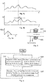
- Figure 3a shows a first graph expressing a first parameter x 1 as a function of time t.
- Figure 3b shows a second graph expressing a second parameter x 2 as a function of time t.
- the first and second parameters x 1 and x 2 may represent a ratio between an amount of gas G and an amount of liquid L in the measurement section M at the positions for the first and second sensor devices S1 and S2 respectively.
- Figure 3c shows a third graph expressing a cross correlation R( ⁇ ) between the first and second parameters x 1 and x 2 for different time offsets ⁇ .
- a is a sampling interval t.
- Figure 4 illustrates how a proposed inductive sensor element measures the speed of a flowing fluid containing gas and liquid.
- a first coil for electric current 410 is arranged on a first side of a conduit 110 for the fluid
- a second coil for electric current 420 is arranged on a second side of the conduit 110 opposite to the first side.
- An alternating voltage U(f) is applied between a pair of terminals connected to the first and second coils 410 and 420 respectively.
- the alternating voltage U(f) may have a frequency f at 20 kHz to 60 kHz, preferably around 40 kHz.
- a voltage ⁇ u(f F ) is also induced in the coils 410 and 420.
- the deviations ⁇ u(f F ) from the applied voltage U(f) represents a measure of the speed of the flowing fluid.
- a first measure in respect of the fluid medium is registered via a first sensor device in a measurement section of a conduit for the fluid medium.
- a second step 520 registers, via a second sensor device in the measurement section, a second measure in respect of the fluid medium.
- the first and second measurers are mutually independent. However, the first and second measures are both dependent on the liquid flow as well as the gas flow in the fluid medium.
- a step 530 derives the flow of the first fluid and/or the flow of the second fluid based on the first and second measures, for instance by using a lookup table or an artificial neural network.
- All of the process steps, as well as any sub-sequence of steps, described with reference to Figure 5 above may be controlled by means of a programmed computer apparatus.
- the embodiments of the invention described above with reference to the drawings comprise computer apparatus and processes performed in computer apparatus, the invention thus also extends to computer programs, particularly computer programs on or in a carrier, adapted for putting the invention into practice.
- the program may be in the form of source code, object code, a code intermediate source and object code such as in partially compiled form, or in any other form suitable for use in the implementation of the process according to the invention.
- the program may either be a part of an operating system, or be a separate application.
- the carrier may be any entity or device capable of carrying the program.
- the carrier may comprise a storage medium, such as a Flash memory, a ROM (Read Only Memory), for example a DVD (Digital Video/Versatile Disk), a CD (Compact Disc) or a semiconductor ROM, an EPROM (Erasable Programmable Read-Only Memory), an EEPROM (Electrically Erasable Programmable Read-Only Memory), or a magnetic recording medium, for example a floppy disc or hard disc.
- the carrier may be a transmissible carrier such as an electrical or optical signal which may be conveyed via electrical or optical cable or by radio or by other means.
- the carrier may be constituted by such cable or device or means.
- the carrier may be an integrated circuit in which the program is embedded, the integrated circuit being adapted for performing, or for use in the performance of, the relevant processes.
- the invention is advantageous in connection with cow milking, the invention is equally well adapted for implementation in milking machines for any other kind of mammals, such as goats, sheep or buffaloes.
Landscapes
- Physics & Mathematics (AREA)
- Fluid Mechanics (AREA)
- General Physics & Mathematics (AREA)
- Life Sciences & Earth Sciences (AREA)
- Animal Husbandry (AREA)
- Environmental Sciences (AREA)
- Measuring Volume Flow (AREA)
Applications Claiming Priority (4)
| Application Number | Priority Date | Filing Date | Title |
|---|---|---|---|
| US201161552523P | 2011-10-28 | 2011-10-28 | |
| SE1151010 | 2011-10-28 | ||
| EP12784094.0A EP2771653B1 (de) | 2011-10-28 | 2012-10-25 | Mehrphasen-flussmessung |
| PCT/SE2012/051148 WO2013062473A1 (en) | 2011-10-28 | 2012-10-25 | Multiphase flow measurement |
Related Parent Applications (2)
| Application Number | Title | Priority Date | Filing Date |
|---|---|---|---|
| EP12784094.0A Division EP2771653B1 (de) | 2011-10-28 | 2012-10-25 | Mehrphasen-flussmessung |
| PCT/SE2012/051148 Previously-Filed-Application WO2013062473A1 (en) | 2011-10-28 | 2012-10-25 | Multiphase flow measurement |
Publications (3)
| Publication Number | Publication Date |
|---|---|
| EP3974784A1 true EP3974784A1 (de) | 2022-03-30 |
| EP3974784C0 EP3974784C0 (de) | 2026-05-06 |
| EP3974784B1 EP3974784B1 (de) | 2026-05-06 |
Family
ID=48168161
Family Applications (2)
| Application Number | Title | Priority Date | Filing Date |
|---|---|---|---|
| EP12784094.0A Active EP2771653B1 (de) | 2011-10-28 | 2012-10-25 | Mehrphasen-flussmessung |
| EP20207786.3A Active EP3974784B1 (de) | 2011-10-28 | 2012-10-25 | Mehrphasen-flussmessung |
Family Applications Before (1)
| Application Number | Title | Priority Date | Filing Date |
|---|---|---|---|
| EP12784094.0A Active EP2771653B1 (de) | 2011-10-28 | 2012-10-25 | Mehrphasen-flussmessung |
Country Status (4)
| Country | Link |
|---|---|
| US (1) | US9719825B2 (de) |
| EP (2) | EP2771653B1 (de) |
| AU (2) | AU2012329603B2 (de) |
| WO (1) | WO2013062473A1 (de) |
Families Citing this family (3)
| Publication number | Priority date | Publication date | Assignee | Title |
|---|---|---|---|---|
| US20170247986A1 (en) | 2014-10-28 | 2017-08-31 | Bryan BUSSELL | Additive management system |
| TR2022005795A1 (tr) * | 2022-04-12 | 2023-10-23 | Agrosus Teknoloji̇ Anoni̇m Şi̇rketi̇ | Bi̇r süt ölçümleme ci̇hazi |
| WO2026005685A1 (en) * | 2024-06-28 | 2026-01-02 | Delaval Holding Ab | Method and sensor arrangement for determining a milk-flow rate, computer program and non-volatile data carrier |
Citations (9)
| Publication number | Priority date | Publication date | Assignee | Title |
|---|---|---|---|---|
| US5116119A (en) | 1991-10-04 | 1992-05-26 | S.C.R. Engineers Ltd. | Method and apparatus for measuring liquid flow |
| FR2722292A1 (fr) * | 1994-07-08 | 1996-01-12 | Inst Francais Du Petrole | Debitmetre polyphasique |
| WO2001029518A1 (en) | 1999-10-18 | 2001-04-26 | Lely Research Holding A.G. | Method and device for measurement of pulsating milk flow |
| EP1155610A2 (de) | 1996-03-13 | 2001-11-21 | Maasland N.V. | Mengenmesser und damit ausgerüstete Vorrichtung zum Melken von Tieren |
| WO2006121480A2 (en) * | 2005-05-10 | 2006-11-16 | Agar Corporation Ltd. | Method and apparatus for measuring multi-streams and multi-phase flow |
| US7155971B2 (en) | 2001-11-16 | 2007-01-02 | Westfaliasurge Gmbh | Method and device for determining the volumetric flow rate of milk flowing during a milking process |
| US20080236298A1 (en) * | 2005-07-07 | 2008-10-02 | Cidra Corporation | Wet Gas Metering Using A Differential Pressure And A Sonar Based Flow Meter |
| WO2009125412A2 (en) * | 2008-04-08 | 2009-10-15 | E.N.G.S. Systems Ltd. | System for measuring milk flow at a milking installation |
| WO2010068118A1 (en) * | 2008-12-12 | 2010-06-17 | Multi Phase Meters As | A method and apparatus for wet gas flow measurements and measurement of gas properties |
Family Cites Families (9)
| Publication number | Priority date | Publication date | Assignee | Title |
|---|---|---|---|---|
| US4751842A (en) | 1987-01-05 | 1988-06-21 | Texaco Inc. | Means and method for measuring a multi-phase distribution within a flowing petroleum stream |
| RU2164340C2 (ru) * | 1997-12-30 | 2001-03-20 | Научно-исследовательский институт измерительных систем | Способ определения покомпонентного расхода потока газожидкостной смеси продуктов газонефтедобычи в трубопроводе и устройство для его реализации |
| NO310322B1 (no) | 1999-01-11 | 2001-06-18 | Flowsys As | Maling av flerfasestromning i ror |
| DE10257322A1 (de) * | 2002-12-06 | 2004-06-24 | Endress + Hauser Flowtec Ag, Reinach | Prozeß-Meßgerät |
| RU2382989C9 (ru) * | 2003-07-15 | 2010-05-10 | Экспроу Митерс, Инк. | Устройство измерения параметров потока |
| US7133786B1 (en) | 2005-06-08 | 2006-11-07 | Roxar Flow Management As | Method and apparatus for measuring nonhomogeneous flow phase velocities |
| WO2009030870A1 (en) | 2007-09-05 | 2009-03-12 | University Of Leeds | Multi phase flow measurement system |
| US8061186B2 (en) | 2008-03-26 | 2011-11-22 | Expro Meters, Inc. | System and method for providing a compositional measurement of a mixture having entrained gas |
| US8646313B2 (en) * | 2009-06-22 | 2014-02-11 | Ford Global Technologies, Llc | System and method to provide lubrication for a plug-in hybrid |
-
2012
- 2012-10-25 AU AU2012329603A patent/AU2012329603B2/en active Active
- 2012-10-25 EP EP12784094.0A patent/EP2771653B1/de active Active
- 2012-10-25 WO PCT/SE2012/051148 patent/WO2013062473A1/en not_active Ceased
- 2012-10-25 US US14/353,547 patent/US9719825B2/en active Active
- 2012-10-25 EP EP20207786.3A patent/EP3974784B1/de active Active
-
2016
- 2016-01-21 AU AU2016200349A patent/AU2016200349B2/en active Active
Patent Citations (9)
| Publication number | Priority date | Publication date | Assignee | Title |
|---|---|---|---|---|
| US5116119A (en) | 1991-10-04 | 1992-05-26 | S.C.R. Engineers Ltd. | Method and apparatus for measuring liquid flow |
| FR2722292A1 (fr) * | 1994-07-08 | 1996-01-12 | Inst Francais Du Petrole | Debitmetre polyphasique |
| EP1155610A2 (de) | 1996-03-13 | 2001-11-21 | Maasland N.V. | Mengenmesser und damit ausgerüstete Vorrichtung zum Melken von Tieren |
| WO2001029518A1 (en) | 1999-10-18 | 2001-04-26 | Lely Research Holding A.G. | Method and device for measurement of pulsating milk flow |
| US7155971B2 (en) | 2001-11-16 | 2007-01-02 | Westfaliasurge Gmbh | Method and device for determining the volumetric flow rate of milk flowing during a milking process |
| WO2006121480A2 (en) * | 2005-05-10 | 2006-11-16 | Agar Corporation Ltd. | Method and apparatus for measuring multi-streams and multi-phase flow |
| US20080236298A1 (en) * | 2005-07-07 | 2008-10-02 | Cidra Corporation | Wet Gas Metering Using A Differential Pressure And A Sonar Based Flow Meter |
| WO2009125412A2 (en) * | 2008-04-08 | 2009-10-15 | E.N.G.S. Systems Ltd. | System for measuring milk flow at a milking installation |
| WO2010068118A1 (en) * | 2008-12-12 | 2010-06-17 | Multi Phase Meters As | A method and apparatus for wet gas flow measurements and measurement of gas properties |
Also Published As
| Publication number | Publication date |
|---|---|
| AU2012329603B2 (en) | 2016-02-11 |
| AU2016200349A1 (en) | 2016-02-11 |
| EP2771653B1 (de) | 2020-11-25 |
| EP2771653A1 (de) | 2014-09-03 |
| US9719825B2 (en) | 2017-08-01 |
| EP3974784C0 (de) | 2026-05-06 |
| AU2012329603A1 (en) | 2014-05-01 |
| WO2013062473A1 (en) | 2013-05-02 |
| US20140260660A1 (en) | 2014-09-18 |
| NZ623675A (en) | 2016-05-27 |
| EP3974784B1 (de) | 2026-05-06 |
| AU2016200349B2 (en) | 2017-06-22 |
Similar Documents
| Publication | Publication Date | Title |
|---|---|---|
| EP2771654B1 (de) | Mehrphasen-flussmessung | |
| Cierpka et al. | Higher order multi-frame particle tracking velocimetry | |
| Meselhe et al. | Large scale particle image velocimetry for low velocity and shallow water flows | |
| NL2010555C2 (nl) | Inrichting voor het bepalen van een massadebiet van een fluã¯dum in een kanaal. | |
| US7155971B2 (en) | Method and device for determining the volumetric flow rate of milk flowing during a milking process | |
| US9316575B2 (en) | Magnetic flow cytometry for individual cell detection | |
| EP2771653B1 (de) | Mehrphasen-flussmessung | |
| US7946184B2 (en) | Electromagnetic flowmeter having temperature measurement value for correcting electrical conductivity value | |
| JP7026204B2 (ja) | 流量計を動作させるための方法、および、プロセス流体を受け取るように構成された流量計の計器エレクトロニクス | |
| CN102213608A (zh) | 用于流量测量仪的校准装置 | |
| EP1893951B1 (de) | Magnetisch-induktives durchflussmessgerät | |
| WO2021030417A1 (en) | Time-accurate cfd enhanced interpretation of strain-based flow measurement | |
| NZ623675B2 (en) | Multiphase flow measurement | |
| GB2513310A (en) | Determination of interfacial or surface tension | |
| NZ623678B2 (en) | Multiphase flow measurement | |
| Brown et al. | Quantitative self-verification, a breakthrough in ultrasonic metering technology | |
| CN110763278A (zh) | 一种测量管道内流体介质参数的测量方法 | |
| US20040194553A1 (en) | Device for determining the mass of flowing, foaming flow of liquid | |
| CN111829600B (zh) | 微升级流量的计量装置及计量方法 | |
| TR2023017303A1 (tr) | Düzgün olmayan akış profillerinde debi ölçüm yöntemi. | |
| CN117191140A (zh) | 一种液体流量计算方法及相关设备 | |
| CN120344931A (zh) | 流体网络的整体多向异常和场景转变检测 | |
| JP3513008B2 (ja) | 交通データ予測システム及び方法 |
Legal Events
| Date | Code | Title | Description |
|---|---|---|---|
| PUAI | Public reference made under article 153(3) epc to a published international application that has entered the european phase |
Free format text: ORIGINAL CODE: 0009012 |
|
| STAA | Information on the status of an ep patent application or granted ep patent |
Free format text: STATUS: REQUEST FOR EXAMINATION WAS MADE |
|
| 17P | Request for examination filed |
Effective date: 20201116 |
|
| AC | Divisional application: reference to earlier application |
Ref document number: 2771653 Country of ref document: EP Kind code of ref document: P |
|
| AK | Designated contracting states |
Kind code of ref document: A1 Designated state(s): AL AT BE BG CH CY CZ DE DK EE ES FI FR GB GR HR HU IE IS IT LI LT LU LV MC MK MT NL NO PL PT RO RS SE SI SK SM TR |
|
| STAA | Information on the status of an ep patent application or granted ep patent |
Free format text: STATUS: EXAMINATION IS IN PROGRESS |
|
| 17Q | First examination report despatched |
Effective date: 20240411 |
|
| GRAP | Despatch of communication of intention to grant a patent |
Free format text: ORIGINAL CODE: EPIDOSNIGR1 |
|
| STAA | Information on the status of an ep patent application or granted ep patent |
Free format text: STATUS: GRANT OF PATENT IS INTENDED |
|
| INTG | Intention to grant announced |
Effective date: 20251201 |
|
| GRAS | Grant fee paid |
Free format text: ORIGINAL CODE: EPIDOSNIGR3 |
|
| GRAA | (expected) grant |
Free format text: ORIGINAL CODE: 0009210 |
|
| STAA | Information on the status of an ep patent application or granted ep patent |
Free format text: STATUS: THE PATENT HAS BEEN GRANTED |
|
| AC | Divisional application: reference to earlier application |
Ref document number: 2771653 Country of ref document: EP Kind code of ref document: P |
|
| AK | Designated contracting states |
Kind code of ref document: B1 Designated state(s): AL AT BE BG CH CY CZ DE DK EE ES FI FR GB GR HR HU IE IS IT LI LT LU LV MC MK MT NL NO PL PT RO RS SE SI SK SM TR |
|
| REG | Reference to a national code |
Ref country code: CH Ref legal event code: F10 Free format text: ST27 STATUS EVENT CODE: U-0-0-F10-F00 (AS PROVIDED BY THE NATIONAL OFFICE) Effective date: 20260506 Ref country code: GB Ref legal event code: FG4D |
|
| REG | Reference to a national code |
Ref country code: DE Ref legal event code: R096 Ref document number: 602012082064 Country of ref document: DE |
|
| REG | Reference to a national code |
Ref country code: IE Ref legal event code: FG4D |
|
| U01 | Request for unitary effect filed |
Effective date: 20260528 |
|
| U07 | Unitary effect registered |
Designated state(s): AT BE BG DE DK EE FI FR IT LT LU LV MT NL PT RO SE SI Effective date: 20260609 |