EP3974778B1 - Procédé et appareil pour mettre à jour une carte de travail d'un robot mobile, et support de stockage - Google Patents
Procédé et appareil pour mettre à jour une carte de travail d'un robot mobile, et support de stockage Download PDFInfo
- Publication number
- EP3974778B1 EP3974778B1 EP20835590.9A EP20835590A EP3974778B1 EP 3974778 B1 EP3974778 B1 EP 3974778B1 EP 20835590 A EP20835590 A EP 20835590A EP 3974778 B1 EP3974778 B1 EP 3974778B1
- Authority
- EP
- European Patent Office
- Prior art keywords
- environment
- mobile robot
- map
- detected
- maps
- Prior art date
- Legal status (The legal status is an assumption and is not a legal conclusion. Google has not performed a legal analysis and makes no representation as to the accuracy of the status listed.)
- Active
Links
- 238000000034 method Methods 0.000 title claims description 180
- 238000001514 detection method Methods 0.000 claims description 96
- 238000012545 processing Methods 0.000 claims description 76
- 230000008569 process Effects 0.000 claims description 71
- 230000002159 abnormal effect Effects 0.000 claims description 14
- 238000012546 transfer Methods 0.000 claims description 7
- 238000011084 recovery Methods 0.000 description 38
- 238000001914 filtration Methods 0.000 description 31
- 238000010586 diagram Methods 0.000 description 26
- 238000004891 communication Methods 0.000 description 22
- 238000010407 vacuum cleaning Methods 0.000 description 21
- 230000004807 localization Effects 0.000 description 19
- 230000004044 response Effects 0.000 description 18
- 238000004140 cleaning Methods 0.000 description 15
- 230000006870 function Effects 0.000 description 12
- 238000012986 modification Methods 0.000 description 6
- 230000004048 modification Effects 0.000 description 6
- 238000007726 management method Methods 0.000 description 5
- 238000013439 planning Methods 0.000 description 5
- 238000007781 pre-processing Methods 0.000 description 5
- 238000013507 mapping Methods 0.000 description 4
- 230000009467 reduction Effects 0.000 description 4
- 230000008878 coupling Effects 0.000 description 3
- 238000010168 coupling process Methods 0.000 description 3
- 238000005859 coupling reaction Methods 0.000 description 3
- 238000005516 engineering process Methods 0.000 description 3
- 230000014509 gene expression Effects 0.000 description 3
- 230000000877 morphologic effect Effects 0.000 description 3
- 238000013528 artificial neural network Methods 0.000 description 2
- 230000008859 change Effects 0.000 description 2
- 238000004590 computer program Methods 0.000 description 2
- 238000013461 design Methods 0.000 description 2
- 230000003993 interaction Effects 0.000 description 2
- 238000005259 measurement Methods 0.000 description 2
- 239000013598 vector Substances 0.000 description 2
- 235000001275 Bouea macrophylla Nutrition 0.000 description 1
- 240000001160 Bouea macrophylla Species 0.000 description 1
- 230000003190 augmentative effect Effects 0.000 description 1
- 230000005540 biological transmission Effects 0.000 description 1
- 238000006243 chemical reaction Methods 0.000 description 1
- 230000001419 dependent effect Effects 0.000 description 1
- 238000011161 development Methods 0.000 description 1
- VJYFKVYYMZPMAB-UHFFFAOYSA-N ethoprophos Chemical compound CCCSP(=O)(OCC)SCCC VJYFKVYYMZPMAB-UHFFFAOYSA-N 0.000 description 1
- 230000004927 fusion Effects 0.000 description 1
- 230000003287 optical effect Effects 0.000 description 1
- 238000002310 reflectometry Methods 0.000 description 1
- 238000000638 solvent extraction Methods 0.000 description 1
- 230000003068 static effect Effects 0.000 description 1
- 230000001360 synchronised effect Effects 0.000 description 1
- 238000012549 training Methods 0.000 description 1
- 238000012384 transportation and delivery Methods 0.000 description 1
Images


Classifications
-
- G—PHYSICS
- G05—CONTROLLING; REGULATING
- G05D—SYSTEMS FOR CONTROLLING OR REGULATING NON-ELECTRIC VARIABLES
- G05D1/00—Control of position, course, altitude or attitude of land, water, air or space vehicles, e.g. using automatic pilots
- G05D1/02—Control of position or course in two dimensions
- G05D1/021—Control of position or course in two dimensions specially adapted to land vehicles
- G05D1/0268—Control of position or course in two dimensions specially adapted to land vehicles using internal positioning means
- G05D1/0274—Control of position or course in two dimensions specially adapted to land vehicles using internal positioning means using mapping information stored in a memory device
-
- G—PHYSICS
- G01—MEASURING; TESTING
- G01C—MEASURING DISTANCES, LEVELS OR BEARINGS; SURVEYING; NAVIGATION; GYROSCOPIC INSTRUMENTS; PHOTOGRAMMETRY OR VIDEOGRAMMETRY
- G01C21/00—Navigation; Navigational instruments not provided for in groups G01C1/00 - G01C19/00
- G01C21/26—Navigation; Navigational instruments not provided for in groups G01C1/00 - G01C19/00 specially adapted for navigation in a road network
- G01C21/28—Navigation; Navigational instruments not provided for in groups G01C1/00 - G01C19/00 specially adapted for navigation in a road network with correlation of data from several navigational instruments
- G01C21/30—Map- or contour-matching
- G01C21/32—Structuring or formatting of map data
-
- A—HUMAN NECESSITIES
- A47—FURNITURE; DOMESTIC ARTICLES OR APPLIANCES; COFFEE MILLS; SPICE MILLS; SUCTION CLEANERS IN GENERAL
- A47L—DOMESTIC WASHING OR CLEANING; SUCTION CLEANERS IN GENERAL
- A47L11/00—Machines for cleaning floors, carpets, furniture, walls, or wall coverings
- A47L11/40—Parts or details of machines not provided for in groups A47L11/02 - A47L11/38, or not restricted to one of these groups, e.g. handles, arrangements of switches, skirts, buffers, levers
- A47L11/4011—Regulation of the cleaning machine by electric means; Control systems and remote control systems therefor
-
- G—PHYSICS
- G01—MEASURING; TESTING
- G01C—MEASURING DISTANCES, LEVELS OR BEARINGS; SURVEYING; NAVIGATION; GYROSCOPIC INSTRUMENTS; PHOTOGRAMMETRY OR VIDEOGRAMMETRY
- G01C21/00—Navigation; Navigational instruments not provided for in groups G01C1/00 - G01C19/00
- G01C21/38—Electronic maps specially adapted for navigation; Updating thereof
- G01C21/3804—Creation or updating of map data
- G01C21/3807—Creation or updating of map data characterised by the type of data
- G01C21/383—Indoor data
-
- G—PHYSICS
- G01—MEASURING; TESTING
- G01C—MEASURING DISTANCES, LEVELS OR BEARINGS; SURVEYING; NAVIGATION; GYROSCOPIC INSTRUMENTS; PHOTOGRAMMETRY OR VIDEOGRAMMETRY
- G01C21/00—Navigation; Navigational instruments not provided for in groups G01C1/00 - G01C19/00
- G01C21/38—Electronic maps specially adapted for navigation; Updating thereof
- G01C21/3804—Creation or updating of map data
- G01C21/3833—Creation or updating of map data characterised by the source of data
- G01C21/3837—Data obtained from a single source
-
- G—PHYSICS
- G01—MEASURING; TESTING
- G01C—MEASURING DISTANCES, LEVELS OR BEARINGS; SURVEYING; NAVIGATION; GYROSCOPIC INSTRUMENTS; PHOTOGRAMMETRY OR VIDEOGRAMMETRY
- G01C21/00—Navigation; Navigational instruments not provided for in groups G01C1/00 - G01C19/00
- G01C21/38—Electronic maps specially adapted for navigation; Updating thereof
- G01C21/3804—Creation or updating of map data
- G01C21/3833—Creation or updating of map data characterised by the source of data
- G01C21/3848—Data obtained from both position sensors and additional sensors
-
- G—PHYSICS
- G01—MEASURING; TESTING
- G01C—MEASURING DISTANCES, LEVELS OR BEARINGS; SURVEYING; NAVIGATION; GYROSCOPIC INSTRUMENTS; PHOTOGRAMMETRY OR VIDEOGRAMMETRY
- G01C21/00—Navigation; Navigational instruments not provided for in groups G01C1/00 - G01C19/00
- G01C21/38—Electronic maps specially adapted for navigation; Updating thereof
- G01C21/3863—Structures of map data
- G01C21/387—Organisation of map data, e.g. version management or database structures
-
- G—PHYSICS
- G05—CONTROLLING; REGULATING
- G05D—SYSTEMS FOR CONTROLLING OR REGULATING NON-ELECTRIC VARIABLES
- G05D1/00—Control of position, course, altitude or attitude of land, water, air or space vehicles, e.g. using automatic pilots
- G05D1/02—Control of position or course in two dimensions
- G05D1/021—Control of position or course in two dimensions specially adapted to land vehicles
- G05D1/0212—Control of position or course in two dimensions specially adapted to land vehicles with means for defining a desired trajectory
- G05D1/0219—Control of position or course in two dimensions specially adapted to land vehicles with means for defining a desired trajectory ensuring the processing of the whole working surface
-
- G—PHYSICS
- G05—CONTROLLING; REGULATING
- G05D—SYSTEMS FOR CONTROLLING OR REGULATING NON-ELECTRIC VARIABLES
- G05D1/00—Control of position, course, altitude or attitude of land, water, air or space vehicles, e.g. using automatic pilots
- G05D1/20—Control system inputs
- G05D1/24—Arrangements for determining position or orientation
- G05D1/246—Arrangements for determining position or orientation using environment maps, e.g. simultaneous localisation and mapping [SLAM]
-
- G—PHYSICS
- G05—CONTROLLING; REGULATING
- G05D—SYSTEMS FOR CONTROLLING OR REGULATING NON-ELECTRIC VARIABLES
- G05D1/00—Control of position, course, altitude or attitude of land, water, air or space vehicles, e.g. using automatic pilots
- G05D1/60—Intended control result
- G05D1/648—Performing a task within a working area or space, e.g. cleaning
-
- G—PHYSICS
- G06—COMPUTING; CALCULATING OR COUNTING
- G06V—IMAGE OR VIDEO RECOGNITION OR UNDERSTANDING
- G06V10/00—Arrangements for image or video recognition or understanding
- G06V10/70—Arrangements for image or video recognition or understanding using pattern recognition or machine learning
- G06V10/77—Processing image or video features in feature spaces; using data integration or data reduction, e.g. principal component analysis [PCA] or independent component analysis [ICA] or self-organising maps [SOM]; Blind source separation
- G06V10/80—Fusion, i.e. combining data from various sources at the sensor level, preprocessing level, feature extraction level or classification level
- G06V10/809—Fusion, i.e. combining data from various sources at the sensor level, preprocessing level, feature extraction level or classification level of classification results, e.g. where the classifiers operate on the same input data
-
- G—PHYSICS
- G06—COMPUTING; CALCULATING OR COUNTING
- G06V—IMAGE OR VIDEO RECOGNITION OR UNDERSTANDING
- G06V20/00—Scenes; Scene-specific elements
- G06V20/10—Terrestrial scenes
-
- G—PHYSICS
- G06—COMPUTING; CALCULATING OR COUNTING
- G06V—IMAGE OR VIDEO RECOGNITION OR UNDERSTANDING
- G06V20/00—Scenes; Scene-specific elements
- G06V20/60—Type of objects
- G06V20/64—Three-dimensional objects
- G06V20/653—Three-dimensional objects by matching three-dimensional models, e.g. conformal mapping of Riemann surfaces
-
- A—HUMAN NECESSITIES
- A47—FURNITURE; DOMESTIC ARTICLES OR APPLIANCES; COFFEE MILLS; SPICE MILLS; SUCTION CLEANERS IN GENERAL
- A47L—DOMESTIC WASHING OR CLEANING; SUCTION CLEANERS IN GENERAL
- A47L2201/00—Robotic cleaning machines, i.e. with automatic control of the travelling movement or the cleaning operation
- A47L2201/04—Automatic control of the travelling movement; Automatic obstacle detection
Definitions
- This disclosure generally relates to the field of intelligent control technologies, and the invention more specifically, relates to a method and an apparatus for updating a working map of a mobile robot, a mobile robot, and a computer storage medium.
- a mobile robot usually obtains an environment layout map in a working environment through simultaneous localization and mapping (simultaneous localization and mapping, SLAM), and then plans a path based on the environment layout map during specific working, to execute a corresponding working task according to a corresponding path.
- simultaneous localization and mapping simultaneous localization and mapping
- the mobile robot (especially a home service robot) usually uses a consumer-level sensor and drive system and has no external auxiliary localization device. Consequently, both localization accuracy and reliability are not high. Therefore, to reduce impact of a single localization anomaly of the mobile robot on path planning, the mobile robot usually does not store an environment layout map. Each time the mobile robot works, the mobile robot re-constructs an environment layout map, and then plans a path based on the newly constructed map (for example, each time the mobile robot starts to execute a task, the mobile robot first roughly detects an ambient environment, constructs an environment layout map based on detected object distribution information, and then plans a path based on the environment layout map).
- the environment layout map obtained in the foregoing mapping manner is usually not comprehensive enough, and cannot reflect a detailed object layout in a workplace.
- CN 193 645 480 A discloses a method for constructing topographic and geomorphic features based on fusion of lidar and image data comprising acquiring a 3D laser point cloud and a panoramic image of an ambient environment of a ground unmanned mobile platform at a current moment, wherein the acquired 3D laser point cloud is a set of feature points of the ambient environment of the platform, comprising the three-dimensional coordinates and reflectivity of each feature point; matching the 3D laser point cloud with the panoramic image to obtain a matched image: for laser points in the 3D laser point cloud, selecting different distribution features corresponding thereto, partitioning the 3D laser point cloud, and performing clustering according to a dynamic clustering algorithm of the distribution features to obtain a plurality of region classes; assessing the terrain of the plurality of region classes according to a driving capability of the ground unmanned mobile platform, to obtain a navigable region class; using a dense SIFT algorithm to obtain terrain recognition vectors of the navigable region class; using a classifier to classify the navigable region class according to the terrain
- background is contained in WO 2018/074 903 A1 and US 2019/332 115 A1 disclosing a method of controlling a mobile robot including a first basic learning process of generating a first basic map based on environment information acquired in a traveling process , a second basic learning process of generating a second basic map based on environment information acquired in a separate traveling process , and a merging process of merging the first basic map and the second basic map to generate a merged map.
- Some further background information may also be found in US 2005/182 518 A1 , US 2017/197 311 A1 , and US 9 612 123 B1 .
- the object of the present invention is to provide a method and an apparatus for updating a working map of a mobile robot, a mobile robot, and a computer storage medium, to obtain a map that can more comprehensively reflect a working environment layout of a mobile robot.
- a method for updating a working map of a mobile robot includes: obtaining M detected environment maps; merging the M detected environment maps to obtain a merged environment map; and performing weighting processing on a pixel value of the merged environment map and a pixel value of an environment layout map to obtain an updated environment layout map.
- the M detected environment maps are determined based on object distribution information detected by a mobile robot in a moving process, and M is an integer greater than 1.
- the detected environment map may be determined based on the object distribution information detected by the mobile robot, and the environment layout map is usually obtained by merging a plurality of detected environment maps.
- Both the detected environment map and the environment layout map can reflect object distribution in a working environment.
- the environment layout map usually can more comprehensively reflect overall object distribution or an overall object layout in the working environment.
- the M detected environment maps When the M detected environment maps are merged (specifically, the M detected environment maps may be superposed) to obtain the merged environment map, the M detected environment maps may be directly merged; or the M detected environment maps may be merged after specific preprocessing (for example, filtering processing or noise reduction processing) is performed on the M detected environment maps; or specific selection may be performed on the M detected environment maps, and then selected detected environment maps are merged.
- specific preprocessing for example, filtering processing or noise reduction processing
- the environment layout map may be obtained by the mobile robot through merging based on a plurality of previously obtained detected environment maps.
- the mobile robot may first perform detection in the workplace, determine a plurality of detected environment maps based on detected object distribution information, and then determine an environment layout map based on the plurality of detected environment maps. Subsequently, the mobile robot may continuously update and optimize the environment layout map according to the method in this application.
- the merging the M detected environment maps to obtain a merged environment map includes: performing filtering processing on the M detected environment maps to obtain M detected environment maps obtained after filtering processing; and merging the M detected environment maps obtained after filtering processing to obtain the merged environment map.
- Filtering processing is performed on the detected environment map, so that interference of a small object in an environment can be removed, thereby reserving a main layout of the environment.
- morphological filtering may be specifically used to extract a line feature of the detected environment map.
- the environment layout map is an environment layout map that is of a first workplace and that is currently stored in the mobile robot.
- the mobile robot may replace the original environment layout map, and store the updated environment layout map. Until next map update, the mobile robot re-updates the environment layout map based on a detected environment map that is detected.
- the environment layout map stored in the mobile robot is updated by using a plurality of detected maps obtained by the mobile robot during working, so that the updated environment layout map can reflect a more detailed environment layout. This helps the mobile robot subsequently better execute a working task based on the updated environment layout map.
- the mobile robot may be controlled to execute a working task in the first place based on the updated environment layout map.
- the updated environment layout map can better and comprehensively reflect object distribution in the first place. Therefore, the mobile robot can better execute a working task in the first place based on the updated environment layout map.
- M is a preset value.
- M may be a value preset by a manufacturer, or may be a value preset by a user.
- the value of M may be flexibly set by using detected environment map quantity configuration information, and a quantity of detected environment maps to be obtained can be directly determined by using the detected environment map quantity configuration information.
- the method further includes: obtaining the detected environment map quantity configuration information, where the detected environment map quantity configuration information includes the value of M; and determining the value of M based on the detected environment map quantity configuration information.
- M can be flexibly set by using the detected environment map quantity configuration information.
- the detected environment map quantity configuration information may be information input by a user.
- the user may input the detected environment map quantity configuration information through a control interface of the control apparatus.
- the control apparatus may be a module integrated into the mobile robot, or may be a separate device independent of the mobile robot.
- the value of M may be adjusted by using the detected environment map quantity modification information, to increase or decrease the value of M.
- the value of M may be adjusted by sending the detected environment map quantity modification information to the control apparatus.
- a weight corresponding to a pixel value of the merged environment map is a first weight
- a weight corresponding to a pixel value of the environment layout map is a second weight. Values of the first weight and the second weight are determined based on a map update requirement of the mobile robot.
- the map update requirement of the mobile robot may be a requirement of the mobile robot (during execution of a task) on a speed (or a frequency) of updating the environment layout map, or may be a requirement of the mobile robot (during execution of a task) on an amplitude of updating the environment layout map.
- the first weight when the mobile robot requires to quickly update the environment layout map, the first weight may be set to a large value, and the second weight may be set to a small value.
- the first weight when the mobile robot does not require to quickly update the environment layout map, the first weight may be set to a small value, and the second weight may be set to a large value.
- the first weight when the mobile robot requires a large amplitude of updating the environment layout map, the first weight may be set to a large value, and the second weight may be set to a small value.
- the first weight when the mobile robot requires a small amplitude of updating the environment layout map, the first weight may be set to a small value, and the second weight may be set to a large value.
- the environment layout map may be flexibly updated based on the map update requirement of the mobile robot.
- that values of the first weight and the second weight are determined based on a map update requirement of the mobile robot includes: the first weight is in a positive correlation with an environment layout map update frequency required by the mobile robot, and the second weight is in a negative correlation with the environment layout map update frequency required by the mobile robot.
- the first weight when the mobile robot (during execution of a task) requires a high map update frequency, the first weight may be set to a large value, and the second weight may be set to a small value (for example, the first weight value is set to 0.7, and the second weight value is set to 0.3).
- the first weight when the mobile robot (during execution of a task) requires a low map update frequency, the first weight may be set to a small value, and the second weight may be set to a large value (for example, the first weight value is set to 0.3, and the second weight value is set to 0.7).
- that values of the first weight and the second weight are determined based on a map update requirement of the mobile robot includes: the first weight is in a positive correlation with an environment layout map update amplitude required by the mobile robot, and the second weight is in a negative correlation with the environment layout map update amplitude required by the mobile robot.
- the merging the M detected environment maps to obtain a merged environment map includes: determining N detected environment maps from the M detected environment maps; and merging the N detected environment maps to obtain the merged environment map.
- Consistency between any two of the N detected environment maps is greater than or equal to a first threshold, and N is a positive integer less than or equal to M.
- Detected environment maps with better consistency are selected from the M detected environment maps and merged, so that a more accurate merged environment map can be obtained.
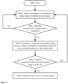
- the method further includes: obtaining current object distribution information; determining a current detected environment map based on the current object distribution information; when consistency between the current detected environment map and the environment layout map is less than a second threshold, determining that the mobile robot is abnormal when detecting an ambient environment; and controlling the mobile robot to recover from an anomaly.
- the current object distribution information is object distribution information detected by the mobile robot in a preset interval or a preset distance
- the preset interval is a time interval before the mobile robot reaches a current detection point
- the preset distance is a distance by which the mobile robot moves before the mobile robot reaches the current detection point.
- the preset interval may be a time interval set by a person, and the preset distance may be a distance set by a person.
- the preset interval and the preset distance may be flexibly set based on a specific requirement.
- That the mobile robot is abnormal when detecting the ambient environment may mean that the mobile robot cannot detect accurate object distribution information in a process of detecting the ambient environment due to a specific fault.
- the mobile robot may be unable to detect the accurate object distribution information due to a localization fault, a sensor fault, or faults of some processing modules inside the mobile robot.
- the controlling the mobile robot to recover from an anomaly includes: controlling the mobile robot to return from the current detection point to a first detection point, where a distance between the first detection point and the current detection point is the preset distance; and controlling the mobile robot to start to re-detect the ambient environment from the first detection point, to obtain new object distribution information.
- controlling the mobile robot to recover from an anomaly includes: controlling the mobile robot to reset an operating system.
- the controlling the mobile robot to reset an operating system is equivalent to controlling the mobile robot to restart a system (similar to restarting a computer).
- controlling the mobile robot to recover from an anomaly includes: controlling the mobile robot to restart a sensor of the mobile robot.
- the controlling the mobile robot to restart a sensor of the mobile robot may be specifically controlling the mobile robot to disable the sensor and then re-enable the sensor.
- the sensor of the mobile robot may include a laser radar, an encoder, a gyroscope, an ultrasonic sensor, an infrared sensor, and the like.
- the method further includes: controlling the mobile robot to clear the current object distribution information.
- the mobile robot is controlled to clear the current object distribution information, so that obtained object distribution information that may be not accurate enough due to a localization anomaly or a sensor fault can be cleared, and accuracy of the object distribution information obtained by the mobile robot can be ensured as far as possible.
- the operation of controlling the mobile robot to clear the current object distribution information may be considered as an additional operation other than anomaly recovery, or may be considered as a part of the anomaly recovery operation.
- the M detected environment maps all are located in a same coordinate system.
- the M detected environment maps are maps located in a same coordinate system, the M detected environment maps can be more precisely merged to obtain a more accurate merged environment map.
- the M detected environment maps all are maps located in a reference coordinate system, and an origin of the reference coordinate system may be at any one of the following locations: a location of a charging station of the mobile robot; a location at which the mobile robot stops after ending a task; or a location of a garbage transfer station that matches the mobile robot.
- a central point of each of the foregoing locations (the location of the charging station, the location at which the mobile robot stops, and the location of the garbage transfer station) or a point at another location (for example, a point at a specific location) can be used as the origin of the reference coordinate system.
- the obtaining M detected environment maps includes: obtaining a first detected environment map in the M detected environment maps, where a coordinate value of a grid point in the first detected environment map is a coordinate value in a first coordinate system; and converting the coordinate value of the grid point in the first detected environment map into the coordinate value in the reference coordinate system.
- the first detected environment map may be, although not claimed, any of the M detected environment maps.
- the first detected environment map may be determined based on object distribution information detected when the mobile robot executes an i th (1 ⁇ i ⁇ M, and i is an integer) working task.
- An origin of the first coordinate system may be determined based on a start location at which the mobile robot executes the i th task.
- the coordinate origin of the first coordinate system may be a start point at which the mobile robot executes the i th task (for example, may be a central point of the start location at which the mobile robot executes the i th task).
- the M detected environment maps are determined based on object distribution information detected when the mobile robot executes a working task in the first workplace.
- the M detected environment maps are determined by using the object distribution information detected when the mobile robot executes a working task, so that the object distribution information can be obtained when the mobile robot executes another task, thereby improving working efficiency.
- the M detected environment maps are respectively determined based on M pieces of object distribution information, and the M pieces of object distribution information are respectively object distribution information obtained by detecting the ambient environment when the mobile robot executes M working tasks in the first workplace.
- Any one of the M detected environment maps is determined based on object distribution information detected when the mobile robot executes a corresponding working task.
- each of the M detected environment maps is determined based on the object distribution information obtained when the mobile robot executes a working task in the first workplace, so that each detected environment map can comprehensively reflect object distribution in the first place as far as possible, and a finally obtained updated environment layout map can comprehensively reflect object distribution in the first place.
- the obtaining M detected environment maps includes: obtaining the detected environment map based on the object distribution information obtained by detecting the ambient environment when the mobile robot executes a working task in the first workplace, until the M detected environment maps are obtained.
- a quantity of obtained detected environment maps may be counted in real time.
- the quantity of the detected environment maps reaches M
- the merged environment map can be determined based on the M detected environment maps.
- the detected environment map may further continue to be obtained.
- M detected environment maps are obtained again, the process in the method in the first aspect may be repeatedly performed.
- the obtaining the detected environment map based on the object distribution information obtained by detecting the ambient environment when the mobile robot executes a working task in the first workplace, until the M detected environment maps are obtained includes: obtaining one detected environment map based on the object distribution information obtained by detecting the ambient environment when the mobile robot executes one working task in the first workplace, until the M detected environment maps are obtained.
- a method for updating a working map of a mobile robot includes: obtaining M detected environment maps from a mobile robot; merging the M detected environment maps to obtain a merged environment map currently obtained through merging; obtaining, from the mobile robot, an environment layout map currently stored in the mobile robot; performing weighting processing on a pixel value of the merged environment map currently obtained through merging and a pixel value of the currently stored environment layout map to obtain an updated environment layout map; and sending the updated environment layout map to the mobile robot.
- the M detected environment maps are determined based on object distribution information detected by a mobile robot in a moving process, and M is an integer greater than 1.
- the currently stored environment layout map is obtained by performing weighting processing on a merged environment map obtained through merging last time and an environment layout map stored last time, and the merged environment map obtained through merging last time is obtained through merging based on M detected environment maps obtained last time.
- the method in the second aspect may be although not claimed, performed by a control apparatus configured to control the mobile robot to work.
- a plurality of detected maps obtained by the mobile robot during working are obtained from the mobile robot to update the environment layout map currently stored in the mobile robot, so that the updated environment layout map can reflect a more detailed environment layout. This helps the mobile robot subsequently better execute a working task based on the updated environment layout map.
- the obtaining M detected environment maps from a mobile robot includes: receiving the M detected environment maps from the mobile robot.
- the M detected environment maps may be obtained from the mobile robot at one time (the mobile robot sends the M detected environment maps) after the mobile robot generates the M detected environment maps, or one detected environment map may be obtained from the mobile robot each time the mobile robot generates the detected environment map (the mobile robot sends one detected environment map each time generating the detected environment map).
- the method further includes: determining whether the M detected environment maps are obtained.
- a quantity of detected environment maps needs to be counted. After a quantity of obtained detected environment maps reaches M, the M detected environment maps are merged.
- the method further includes although not claimed: obtaining current object distribution information from the mobile robot; determining a current detected environment map based on the current object distribution information; when consistency between the current detected environment map and the currently stored environment layout map is less than a second threshold, determining that the mobile robot is abnormal when detecting an ambient environment; and sending an anomaly recovery instruction to the mobile robot.
- the current object distribution information is object distribution information detected by the mobile robot in a preset interval or a preset distance
- the preset interval is a time interval before the mobile robot reaches a current detection point
- the preset distance is a distance by which the mobile robot moves before the mobile robot reaches the current detection point.
- the anomaly recovery instruction is used to instruct the mobile robot to recover from an anomaly. After receiving the anomaly recovery instruction, the mobile robot recovers from the anomaly in response to the anomaly recovery instruction.
- the recovering from an anomaly includes: sending a return instruction to the mobile robot; and sending a re-detection instruction to the mobile robot.
- the return instruction is used to instruct the mobile robot to return from the current detection point to a first detection point, and a distance between the first detection point and the current detection point is the preset distance. After receiving the return instruction, the mobile robot returns from the current detection point to the first detection point in response to the return instruction.
- the re-detection instruction is used to instruct the mobile robot to start to re-detect the ambient environment from the first detection point, to obtain new object distribution information. After receiving the re-detection instruction, the mobile robot starts to re-detect the ambient environment from the first detection point in response to the re-detection instruction, to obtain new object distribution information.
- the recovering from an anomaly includes: sending a restart instruction to the mobile robot.
- the restart instruction is used to instruct the mobile robot to restart, and re-detect the ambient environment after restarts. After the mobile robot receives the restart instruction, the mobile robot restarts in response to the restart instruction, and re-detects the ambient environment after restarts.
- the restart instruction may not only instruct the mobile robot to reset an operating system, but also instruct the mobile robot to restart a corresponding sensor.
- Restarting the operating system is similar to restarting a computer system, and restarting the sensor may be specifically disabling a port of the sensor and then re-enabling the port of the sensor.
- the sensor of the mobile robot may include a laser radar, an encoder, a gyroscope, an ultrasonic sensor, an infrared sensor, and the like.
- the method further includes: sending a clear instruction to the mobile robot.
- the clear instruction is used to clear the current object distribution information. After receiving the clear instruction, the mobile robot clears the current object distribution information in response to the clear instruction.
- the mobile robot is controlled to clear the current object distribution information, so that obtained object distribution information that may be not accurate enough due to a localization anomaly or a sensor fault can be cleared, and accuracy of the object distribution information obtained by the mobile robot can be ensured as far as possible.
- the M detected environment maps all are located in a same coordinate system.
- the M detected environment maps are located in a same coordinate system. Therefore, the M detected environment maps are more precisely merged to obtain a more accurate merged environment map.
- the M detected environment maps all are maps located in a reference coordinate system, and an origin of the reference coordinate system may be at any one of the following locations: a location of a charging station of the mobile robot; a location at which the mobile robot stops after ending a task; or a location of a garbage transfer station that matches the mobile robot.
- a central point of any one of the foregoing locations or a point at another specific location can be used as the origin of the reference coordinate system.
- a method for updating a working map of a mobile robot includes: detecting an ambient environment in a moving process to obtain environment layout information; determining a detected environment map based on the environment layout information detected in a detection cycle; sending M detected environment maps to a control apparatus; and receiving an updated environment layout map from the control apparatus.
- the updated environment layout map is obtained by the control apparatus by performing weighting processing on a pixel value of a merged environment map currently obtained through merging and a pixel value of a currently stored environment layout map, and the merged environment map currently obtained through merging is obtained by merging the M detected environment maps.
- the M detected environment maps are determined based on object distribution information detected by the mobile robot in a moving process, and M is an integer greater than 1.
- the currently stored environment layout map is obtained by performing weighting processing on a merged environment map obtained through merging last time and an environment layout map stored last time, and the merged environment map obtained through merging last time is obtained through merging based on M detected environment maps obtained last time.
- the method in the third although not claimed, aspect may be performed by a mobile robot.
- the mobile robot obtains the M detected maps during working, and sends the M detected environment maps to the control apparatus, so that the control apparatus can update, based on the M detected environment maps, the environment layout map currently stored in the mobile robot, and the updated environment layout map can reflect a more detailed environment layout. This helps the mobile robot subsequently better execute a working task based on the updated environment layout map.
- the mobile robot sends the M detected environment maps to the control apparatus may be as follows: The mobile robot sends the M detected environment maps to the control apparatus after generating all the M detected environment maps; or the mobile robot sends one detected environment map to the control apparatus each time generating the detected environment map, until the M detected environment maps are sent to the control apparatus.
- the method further includes: sending current object distribution information to the control apparatus, so that the control apparatus determines a current detected environment map based on the current object distribution information; and receiving an anomaly recovery instruction sent by the control apparatus, and recovering from an anomaly in response to the anomaly recovery instruction.
- the current object distribution information is object distribution information detected by the mobile robot in a preset interval or a preset distance
- the preset interval is a time interval before the mobile robot reaches a current detection point
- the preset distance is a distance by which the mobile robot moves before the mobile robot reaches the current detection point.
- the anomaly recovery instruction is generated by the control apparatus when consistency between the current detected environment map and the currently stored environment layout map is less than a second threshold.
- the control apparatus determines that the mobile robot is abnormal when detecting the ambient environment, and sends the anomaly recovery instruction to the mobile robot.
- the anomaly recovery instruction is used to instruct the mobile robot to recover from an anomaly. After receiving the anomaly recovery instruction, the mobile robot recovers from the anomaly in response to the anomaly recovery instruction.
- the receiving an anomaly recovery instruction sent by the control apparatus, and recovering from an anomaly in response to the anomaly recovery instruction includes: receiving a return instruction and a re-detection instruction that are sent by the control apparatus; returning from the current detection point to a first detection point in response to the return instruction; and starting to re-detect the ambient environment from the first detection point in response to the re-detection instruction, to obtain new object distribution information.
- the return instruction and the re-detection instruction may be two specific instructions in the anomaly recovery instruction.
- the anomaly recovery instruction may further include a restart instruction, and the restart instruction is used to instruct the mobile robot to restart, and re-detect the ambient environment after restarts. After the mobile robot receives the restart instruction, the mobile robot restarts in response to the restart instruction, and re-detects the ambient environment after restarts.
- the restart instruction may not only instruct the mobile robot to reset an operating system, but also instruct the mobile robot to restart a corresponding sensor.
- Restarting the operating system is similar to restarting a computer system, and restarting the sensor may be specifically disabling a port of the sensor and then re-enabling the port of the sensor.
- the sensor of the mobile robot may include a laser radar, an encoder, a gyroscope, an ultrasonic sensor, an infrared sensor, and the like.
- the method further includes: receiving a clear instruction sent by the control apparatus; and clearing the current object distribution information in response to the clear instruction.
- the current object distribution information is cleared, so that obtained object distribution information that may be not accurate enough due to a localization anomaly or a sensor fault can be cleared, and accuracy of the object distribution information obtained by the mobile robot can be ensured as far as possible.
- the M detected environment maps are located in a same coordinate system. Therefore, the M detected environment maps are more precisely merged to obtain a more accurate merged environment map.
- the M detected environment maps all are maps located in a reference coordinate system, and an origin of the reference coordinate system may be at any one of the following locations: a location of a charging station of the mobile robot; a location at which the mobile robot stops after ending a task; or a location of a garbage transfer station that matches the mobile robot.
- a central point of any one of the foregoing locations or a point at another specific location can be used as the origin of the reference coordinate system.
- a method for updating a working map of a mobile robot includes: detecting an ambient environment in a moving process to obtain environment layout information; determining a detected environment map based on the environment layout information detected in a detection cycle; when M detected environment maps are obtained, merging the M detected environment maps to obtain a merged environment map currently obtained through merging; and performing weighting processing on a pixel value of the merged environment map currently obtained through merging and a pixel value of a currently stored environment layout map to obtain an updated environment layout map.
- the currently stored environment layout map is obtained by performing weighting processing on a merged environment map obtained through merging last time and an environment layout map stored last time, and the merged environment map obtained through merging last time is obtained through merging based on M detected environment maps obtained last time.
- the method in the fourth although not claimed aspect may be performed by a mobile robot.
- a plurality of detected maps obtained by the mobile robot during working are obtained to update the environment layout map currently stored in the mobile robot, so that the updated environment layout map can reflect a more detailed environment layout. This helps the mobile robot subsequently better execute a working task based on the updated environment layout map.
- the method before the merging the M detected environment maps, the method further includes: determining whether the M detected environment maps are obtained.
- a quantity of detected environment maps may be counted to determine whether a quantity of generated detected environment maps reaches M.
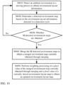
- the method further includes: determining a current detected environment map based on current object distribution information; when consistency between the current detected environment map and the currently obtained environment layout map is less than a second threshold, determining that the mobile robot is abnormal when detecting the ambient environment; and recovering from an anomaly.
- the current object distribution information is object distribution information detected by the mobile robot in a preset interval or a preset distance
- the preset interval is a time interval before the mobile robot reaches a current detection point
- the preset distance is a distance by which the mobile robot moves before the mobile robot reaches the current detection point.
- the recovering from an anomaly includes: returning from the current detection point to a first detection point, where a distance between the first detection point and the current detection point is the preset distance; and starting to re-detect the ambient environment from the first detection point, to obtain new object distribution information.
- the mobile robot may control a movement platform of the mobile robot to return from the current detection point to the first detection point.
- the mobile robot may control a sensor to re-detect the ambient environment, to obtain new object distribution information.
- the method further includes: clearing the current object distribution information.
- the mobile robot may erase the current object distribution information stored in a storage module.
- the recovering from an anomaly includes: performing a restart operation.
- the ambient environment can be re-detected after the restart.
- the restart operation may be resetting an operating system, or may be restarting a corresponding sensor.
- Restarting the operating system is similar to restarting a computer system, and restarting the sensor may be specifically disabling a port of the sensor and then re-enabling the port of the sensor.
- the sensor of the mobile robot may include a laser radar, an encoder, a gyroscope, an ultrasonic sensor, an infrared sensor, and the like.
- extension and description of a corresponding process for example, a merged environment map generation process, a map update process, or the like
- corresponding information for example, the detected environment map
- an apparatus for updating a working map of a mobile robot includes modules configured to perform the method in the first aspect.
- a mobile robot is provided, and the mobile robot includes modules configured to perform the method in the third aspect or the fourth aspect.
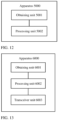
- an apparatus for updating a working map of a mobile robot includes: a memory, configured to store a program; and a processor, configured to execute the program stored in the memory.
- the processor is configured to perform the method in the first aspect.
- an apparatus for updating a working map of a mobile robot includes: a transceiver; a memory, configured to store a program; and a processor, configured to execute the program stored in the memory.
- the transceiver and the processor are configured to perform the method in the second aspect.
- a mobile robot includes: a transceiver; a memory, configured to store a program; and a processor, configured to execute the program stored in the memory.
- the transceiver and the processor are configured to perform the method in the third aspect.
- a mobile robot includes: a memory, configured to store a program; and a processor, configured to execute the program stored in the memory.
- the processor is configured to perform the method in the first aspect.
- a computer storage medium stores program code, and the program code includes instructions used to perform the steps in the method in the first aspect.
- the storage medium may be specifically a nonvolatile storage medium.
- a computer program product including instructions is provided.
- the computer program product runs on a computer, the computer is enabled to perform the method in any one of the first aspect, the second aspect, the third aspect, and the fourth aspect.
- a chip includes a processor and a data interface.
- the processor reads, through the data interface, instructions stored in a memory to perform the method in any one of the first aspect, the second aspect, the third aspect, and the fourth aspect.
- the chip may further include the memory.
- the memory stores the instructions
- the processor is configured to execute the instructions stored in the memory.
- the processor is configured to perform the method in any one of the first aspect, the second aspect, the third aspect, and the fourth aspect.
- the chip may be specifically although not claimed a field programmable gate array FPGA or an application-specific integrated circuit ASIC.
- a mobile robot in this application may be a robot that can move in an indoor environment (for example, an environment such as a home, a shopping center, or a factory workshop) and execute a specific task.
- the mobile robot may include a vacuum cleaning robot, an autonomous mobile robot, and the like.
- FIG. 1 shows a common vacuum cleaning robot, and the vacuum cleaning robot may be charged by using a charging station.
- the mobile robot When executing a task, the mobile robot usually first obtains object distribution in a corresponding workplace, that is, first obtains an environment layout map in the workplace, and then executes a specific task based on the environment layout map.
- object distribution in a same workplace may change. Therefore, to enable the mobile robot to better execute a working task, a working map of the mobile robot needs to be updated.
- a method for updating a working map of a mobile robot in the embodiments of this application is described below in detail with reference to FIG. 2 .
- FIG. 2 is a schematic flowchart of a method for updating a working map of a mobile robot according to an embodiment of this application.
- the method shown in FIG. 2 may be performed by a control apparatus of the mobile robot.
- the control apparatus is configured to update the working map of the mobile robot.
- the control apparatus may be a control module located inside the mobile robot, or may be an independent device located outside the mobile robot.
- the control apparatus may be an electronic device.
- the electronic device may be specifically a mobile terminal (for example, a smartphone), a tablet computer, a notebook computer, an augmented reality/virtual reality device, a wearable device, or the like.
- the method shown in FIG. 2 includes steps 1001 to 1003. The following separately describes the steps in detail.
- the M detected environment maps may be determined based on object distribution information detected by the mobile robot in a moving process.
- the mobile robot In a first workplace, the mobile robot detects a surrounding object to obtain the object distribution information.
- the obtaining M detected environment maps includes: controlling the mobile robot to detect the surrounding object to obtain the object distribution information in the first place; and determining the M detected environment maps based on the object distribution information in the first place.
- the detected environment map obtained in step 1001 may be shown in FIG. 3 .
- the detected environment map displays a contour line or a boundary line of an object in a home environment.
- the detected environment map is determined based on object distribution information obtained when the mobile robot detects a surrounding object in the home environment.
- a value of M is a preset.
- a specific value of M may be set by a manufacturer before delivery, or may be set by a user before the mobile robot performs detection.
- the value of M may be flexibly set by using detected environment map quantity configuration information.
- the method shown in FIG. 1 further includes: obtaining the detected environment map quantity configuration information, where the detected environment map quantity configuration information includes the value of M; and determining the value of M based on the detected environment map quantity configuration information.
- M can be flexibly set by using the detected environment map quantity configuration information, so that a corresponding quantity of detected environment maps can be obtained based on a requirement.
- the detected environment map quantity configuration information may be information input by a user.
- the user may input the detected environment map quantity configuration information through a control interface of the control apparatus.
- the detected environment map quantity configuration information includes a specific value of M.
- the value of M may be further adjusted by using the detected environment map quantity modification information.
- the user may input detected environment map quantity modification information to the control apparatus. After receiving the detected environment map quantity modification information, the control apparatus can adjust the value of M based on the detected environment map quantity modification information.
- the M detected environment maps are determined based on object distribution information detected when the mobile robot executes a working task in the first workplace.
- the M detected environment maps are determined by using the object distribution information detected when the mobile robot executes a working task, so that the object distribution information can be obtained when the mobile robot executes another task, thereby improving working efficiency.
- the M detected environment maps are respectively determined based on M pieces of object distribution information, and the M pieces of object distribution information are respectively object distribution information obtained by detecting an ambient environment when the mobile robot executes M working tasks in the first workplace.
- any one of the M detected environment maps is determined based on object distribution information detected when the mobile robot executes a corresponding working task.
- an i th detected environment map in the M detected environment maps may be determined based on object distribution information obtained by detecting an ambient environment when the mobile robot executes a j th working task, where both i and j are positive integers, 1 ⁇ i ⁇ M, 1 ⁇ j ⁇ M, and i and j may be the same or may be different.
- each of the M detected environment maps is determined based on the object distribution information obtained when the mobile robot executes a working task in the first workplace, so that each detected environment map can comprehensively reflect object distribution in the first place as far as possible, and a finally obtained updated environment layout map can comprehensively reflect object distribution in the first place.
- the obtaining M detected environment maps includes: obtaining the detected environment map based on the object distribution information obtained by detecting the ambient environment when the mobile robot executes a working task in the first workplace, until the M detected environment maps are obtained.
- the detected environment maps may be obtained one by one until a quantity of detected environment maps reaches M.
- a quantity of obtained detected environment maps may be counted in real time.
- a merged environment map can be determined based on the M detected environment maps.
- the detected environment map may further continue to be obtained.
- M detected environment maps are obtained again, the merged environment map is determined again based on the obtained M detected environment maps.
- the mobile robot may detect the ambient environment by using a sensor or a detector of the mobile robot, to obtain surrounding object distribution information.
- the sensor or detector may specifically include at least one of a camera (which may be specifically a depth camera), an infrared sensor, a ranging radar, and an ultrasonic sensor.
- a detected environment map set C (which is referred to as a set C below for short) may be further created in a map update process.
- the set C is used to store an obtained detected environment map.
- the M detected environment maps in the set C all may be written into an environment layout map update set D (which is referred to as a set D below for short), and the detected environment maps stored in the set C are cleared (a detected environment map obtained subsequently may be stored in the set C). In this way, the M detected environment maps in the set D are used to determine the merged environment map.
- an abnormal detected environment map in the set D may be eliminated to obtain an environment layout map update set Ds, and then the merged environment map is determined by using detected environment maps in the set Ds.
- the M detected environment maps When the M detected environment maps are merged (specifically, the M detected environment maps may be superposed) to obtain the merged environment map in step 1002, the M detected environment maps may be directly merged; or the M detected environment maps may be merged after specific preprocessing (for example, filtering processing or noise reduction processing) is performed on the M detected environment maps; or specific selection may be performed on the M detected environment maps, and then selected detected environment maps are merged.
- specific preprocessing for example, filtering processing or noise reduction processing
- step 1002 There may be three different manners of determining the merged environment map in step 1002, and the two manners are separately described below in detail.
- the M detected environment maps are directly merged to obtain the merged environment map currently obtained through merging.
- the M detected environment maps are obtained, the M detected environment maps are directly merged, so that the merged environment map can be conveniently and quickly determined.
- detected environment maps with better consistency are determined from the M detected environment maps and are then merged.
- the merging the M detected environment maps to obtain a merged environment map currently obtained through merging specifically includes: determining N detected environment maps from the M detected environment maps; and merging the N detected environment maps to obtain the merged environment map currently obtained through merging.
- the first threshold may be a preset threshold, and a value of the first threshold may be set based on a requirement.
- the first threshold may be set to a large value.
- the first threshold may be set to a small value. For example, the first threshold may be set to 0.7.
- consistency between two detected environment maps may be represented a degree of matching between grids of the two detected environment maps. If a degree of matching between grids of two detected environment maps is higher, consistency between the two detected environment maps is higher.
- O mn j is a grid point on the map Mj ; m and n are indexes of O mn j , r is a radius of a neighboring area in which the grid point O mn j on the map Mj corresponds to a grid point on the map Mi, and herein a value of r may be 2.
- consistency between any two of the M detected maps may be calculated by using the formulas (1) and (2), and detected environment maps with consistency meeting a requirement (which may be greater than a specific threshold) may be selected from the M detected maps.
- a process of merging the N detected environment maps is similar to the foregoing process of merging the M detected environment maps. Details are not described herein again.
- detected environment maps with better consistency are selected from the M detected environment maps and merged, so that a more accurate merged environment map usually can be obtained.
- the M detected environment maps are preprocessed, and then preprocessed M detected environment maps are merged to obtain the merged environment map currently obtained through merging.
- the merging the M detected environment maps to obtain a merged environment map currently obtained through merging specifically includes: preprocessing the M detected environment maps to obtain preprocessed M detected environment maps; and merging the preprocessed M detected environment maps to obtain the merged environment map currently obtained through merging.
- the preprocessing the M detected environment maps may be as follows: When there is an image area that is in one of the M detected maps and that has image content with a large difference from that in another detected environment map, the image content in the image area is deleted.
- the M detected environment maps include a first detected environment map, and image content in an area A in the first detected environment map is different from that in another detected environment map (a detected environment map other than the first detected environment map in the M detected environment maps) in the M detected environment maps.
- the image content in the area A in the first detected environment map may be deleted or cleared to obtain preprocessed first detected environment map.
- Consistency between any two of the preprocessed M detected environment maps may be greater than or equal to a third threshold.
- the third threshold may be a preset threshold, and a value of the third threshold may be set based on an actual requirement. When the robot has a high requirement on map precision during working, the third threshold may be set to a large value. However, when the robot has a low requirement on map precision during working, the third threshold may be set to a small value.
- the third threshold in the third manner and the first threshold in the second manner may be the same or may be different.
- image content that is in the M detected environment maps and that has a large difference from that in another detected environment map is removed, and then the detected environment maps are merged, so that a more accurate merged environment map usually can be obtained.
- filtering processing or noise reduction processing may be performed on the M detected environment maps before subsequent processing is performed.
- step 1002 before the merged environment map is determined based on the M detected environment maps, the detected environment maps are first filtered, and then the merged environment map is determined based on detected environment maps obtained after filtering processing.
- the determining a merged environment map based on the M detected environment maps includes: performing filtering processing on the M detected environment maps to obtain M detected environment maps obtained after filtering processing; and merging the M detected environment maps obtained after filtering processing to obtain the merged environment map currently obtained through merging.
- the filtering processing herein may be specifically morphological filtering to extract a line feature of an image.
- Filtering processing is performed on the detected environment map, so that interference of a small object in an environment can be removed, thereby reserving a main layout of the environment.
- a detected environment map before filtering processing may be shown in FIG. 3 , and filtering processing may be performed on the detected environment map shown in FIG. 3 to obtain a detected environment map shown in FIG. 4 .
- the detected environment map in FIG. 4 has less image noise and can display a main layout of an environment.
- step 1002 the set C stores M detected environment maps, and the M detected environment maps are written into the set D; and then an abnormal map in the set D is removed to obtain the set Ds, where the set Ds includes N detected environment maps.
- the merged environment map is determined based on the N detected environment maps in the set Ds, the following steps may be performed.
- Step A Obtain a map boundary (x min , x max ) and (y min , y max ) of the merged environment map based on the set Ds.
- the map boundary of the merged environment map may be determined according to formulas (3) and (4).
- Step B Determine the merged environment map based on the set Ds.
- a size of the merged environment map may be first determined based on the map boundary of the merged environment map. Then a merged environment map that uses (x min , y min ) as an image origin (the image origin is located at an upper left corner of the merged environment map) is created, and grid points in the N detected maps in the set Ds are sequentially projected into the merged environment map. Values of pixels of the merged environment map are a set of pixel values of pixels of the N detected maps in the set Ds.
- the merged environment map may be determined according to formula (5).
- O ij M _ pre is a pixel value of a pixel (i, j) in a map M_pre
- O ij M _ k is a corresponding pixel value in a map M_k.
- the merged environment map may be obtained according to formula (5), and the merged environment map may be denoted as Mpre. Filtering processing may be performed on Mpre to obtain a merged environment map obtained after filtering processing, which is denoted as Mobs.
- the environment layout map is an environment layout map that is of the first workplace and that is currently stored in the mobile robot. After completing updating of the environment layout map to obtain the updated environment layout map, the mobile robot may replace the original environment layout map, and store the updated environment layout map. Until next map update, the mobile robot re-updates the environment layout map based on a detected environment map that is detected.
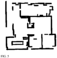
- the environment layout map or the updated environment layout map in step 1003 may be shown in FIG. 5 .
- the environment layout map shown in FIG. 5 displays an object layout in a home environment.
- the environment layout map stored in the mobile robot is updated by using a plurality of detected maps obtained by the mobile robot during working, so that the updated environment layout map can reflect a more detailed environment layout. This helps the mobile robot subsequently better execute a working task based on the updated environment layout map.
- a weight corresponding to the pixel value of the merged environment map currently obtained through merging is a first weight
- a weight corresponding to the pixel value of the currently stored environment layout map is a second weight.
- the first weight and the second weight may be determined based on a map update requirement of the mobile robot.
- the map update requirement of the mobile robot may be a requirement of the mobile robot (during execution of a task) on a speed (or a frequency) of updating the environment layout map, or may be a requirement of the mobile robot (during execution of a task) on an amplitude of updating the environment layout map.
- the first weight when the mobile robot requires to quickly update the environment layout map, the first weight may be set to a large value, and the second weight may be set to a small value.
- the first weight when the mobile robot does not require to quickly update the environment layout map, the first weight may be set to a small value, and the second weight may be set to a large value.
- the first weight when the mobile robot requires a large amplitude of updating the environment layout map, the first weight may be set to a large value, and the second weight may be set to a small value.
- the first weight when the mobile robot requires a small amplitude of updating the environment layout map, the first weight may be set to a small value, and the second weight may be set to a large value.
- the environment layout map may be flexibly updated based on the map update requirement of the mobile robot.
- values of the first weight and the second weight are determined based on a map update requirement of the mobile robot includes: the first weight is in a positive correlation with an environment layout map update frequency required by the mobile robot, and the second weight is in a negative correlation with the environment layout map update frequency required by the mobile robot.
- the first weight when the mobile robot (during execution of a task) requires a high map update frequency, the first weight may be set to a large value, and the second weight may be set to a small value (for example, the first weight value is set to 0.7, and the second weight value is set to 0.3).
- the first weight when the mobile robot (during execution of a task) requires a low map update frequency, the first weight may be set to a small value, and the second weight may be set to a large value (for example, the first weight value is set to 0.3, and the second weight value is set to 0.7).
- values of the first weight and the second weight are determined based on a map update requirement of the mobile robot includes: the first weight is in a positive correlation with an environment layout map update amplitude required by the mobile robot, and the second weight is in a negative correlation with the environment layout map update amplitude required by the mobile robot.
- first weight and the second weight may be preset.
- the first weight and the second weight are set by a user.
- the user may change the values of the first weight and the second weight through a control interface.
- the user may indirectly set the first weight and the second weight by setting another parameter.
- the user may indirectly set the first weight and the second weight by setting a map update frequency parameter.
- the environment layout map may be flexibly updated based on the map update requirement of the mobile robot.
- the environment layout map in step 1003 may be denoted as Mr.
- the map Mr may be updated according to formula (6) to obtain the updated environment layout map.
- M r _ new ⁇ ⁇ M r _ old + 1 ⁇ ⁇ ⁇ M obs
- M r_old represents the environment layout map
- M r_new represents the updated environment layout map
- M obs represents a merged environment map obtained after filtering processing
- ⁇ is a weight (which is equivalent to the second weight in the foregoing description) of M r_old
- (1- ⁇ ) is a weight (which is equivalent to the first weight in the foregoing description) of M obs .
- a value of ⁇ may be specifically 0.7. In this case, during merging, the weight of M r_old is 0.7, and the weight of M obs is 0.3.
- a value of a pixel in M r_new is compared with a grid threshold. If the pixel value is greater than the threshold (the threshold may be set to 180 in this application), the pixelis an occupied point in an environment; or if the pixel value is not greater than the threshold, the pixelis considered as a free point.
- the threshold may be set to 180 in this application
- the environment layout map may be actually considered as a probability map, and the pixel value of the environment layout map ranges from 0 to 255, where 0 indicates that a grid point/a pixel is occupied (there is an obstacle), 255 indicates that a grid point is idle (there is no obstacle), another value indicates a probability of being idle (a value closer to 255 indicates a greater probability of being idle).
- each of the M detected environment maps may be determined based on object distribution information detected when the mobile robot executes a task.
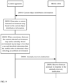
- FIG. 6 is used as an example below for detailed description.
- FIG. 6 is a schematic diagram of a process of obtaining M detected environment maps.
- the process shown in FIG. 6 includes steps 1001a to 1001f. These steps may be considered as a refinement or specific implementation of step 1001. These steps are described below in detail.
- Step 1001a indicates that the M detected environment maps start to be obtained.
- a mobile robot may detect the ambient environment (or a surrounding object) by using a detector or a sensor (the detector or the sensor may be specifically a camera, an infrared sensor, a ranging radar, and an ultrasonic sensor) of the mobile robot under control of a control apparatus (the control apparatus may be a separate control device or may be a control module located inside the mobile robot), to obtain the object distribution information that reflects surrounding object distribution.
- a detector or a sensor the detector or the sensor may be specifically a camera, an infrared sensor, a ranging radar, and an ultrasonic sensor
- the mobile robot may determine whether execution of the current task is completed.
- a vacuum cleaning robot is used as an example.
- the vacuum cleaning robot may specifically determine whether a currently cleaned area meets a preset requirement or whether cleaning time meets a preset requirement. If the currently cleaned area meets the preset requirement or the cleaning time meets the preset requirement, the vacuum cleaning robot can determine that execution of the current task is completed.
- step 1001d is performed to determine a detected environment map.
- step 1001b may be re-performed.
- the mobile robot may send the object distribution information obtained in the execution process of the current task to the control apparatus, and the control apparatus (the control apparatus may be a separate control device or a control module located inside the mobile robot) determines a detected environment map based on the object distribution information.
- step 1001f is performed, that is, M detected environment maps are obtained.
- step 1001b is re-performed.
- the control apparatus may count a quantity of obtained detected environment maps. When the quantity of detected environment maps does not reach M, the control apparatus continues to control the mobile robot to obtain the object distribution information until M detected environment maps are obtained.
- a detected environment map may be determined based on (all) object distribution information obtained in each task execution process.
- a detected environment map may alternatively be determined based on some object distribution information obtained in each task execution process.
- one or more detected environment maps may be determined based on all the object distribution information obtained in each task execution process.
- a detected environment map may be determined based on (all) object distribution information obtained in a process of executing a plurality of tasks by the mobile robot.
- a detected environment map may be determined based on all object distribution information obtained in a process of executing one task by the mobile robot, or may be determined based on some object distribution information obtained in a process of executing one task by the mobile robot, or may be determined based on some object distribution information obtained in a process of executing a plurality of (two or more) tasks by the mobile robot.
- a real-time detected environment map corresponding to specific preset time may be obtained based on object distribution information obtained by the mobile robot in the preset time, and then the real-time detected environment map is compared with an environment layout map currently stored in the mobile robot. If a difference between the real-time detected environment map and the currently stored environment layout map is large, the large difference may be caused by the following: The object distribution information obtained in the current period of time is not accurate enough due to a localization fault or anomaly. In this case, the object distribution information obtained in the current period of time may be discarded, to ensure accuracy of the obtained M detected environment maps.
- object distribution information that may be obtained due to a localization anomaly may be excluded, so that the obtained object distribution information is more accurate.
- FIG. 7 is a schematic diagram of a process of obtaining object distribution information according to an embodiment of this application.
- the process shown in FIG. 7 includes steps 2001 to 2007. These steps may occur in the process of obtaining the M detected environment maps in step 1001. The steps 2001 to 2007 are described below in detail.
- Step 2001 indicates that a current detected map starts to be obtained.
- the current object distribution information is object distribution information detected by the mobile robot in a preset interval or a preset distance
- the preset interval is a time interval before the mobile robot reaches a current detection point
- the preset distance is a distance by which the mobile robot moves before the mobile robot reaches the current detection point.
- the preset interval may be a time interval set by a person, and the preset distance may be a distance set by a person.
- the preset interval and the preset distance may be flexibly set based on a specific requirement.
- the current detected environment map in step 2003 may be specifically obtained in the following two manners.
- Manner A The current detected environment map is determined based on object distribution information obtained by the mobile robot in a preset period of time.
- the current detected environment map may be determined based on object distribution information obtained by the mobile robot each time the mobile robot works for five minutes.
- the current detected environment map may be determined based on object distribution information obtained in any other time length.
- Manner B The current detected environment map is determined based on object distribution information obtained by the mobile robot in the preset distance.
- the current detected environment map may be determined based on object distribution information obtained by the mobile robot each time the mobile robot moves five meters.
- the current detected environment map may be determined based on object distribution information obtained by the mobile robot when the mobile robot moves any other distance.
- step 2004 When it is determined in step 2004 that consistency between the current detected environment map and the environment layout map is less than the second threshold, it indicates that a difference between the current detected environment map and the environment layout map is large. This may be caused by the following: The obtained object distribution information is not accurate due to inaccurate localization, a fault of a sensor, or a fault of another module, and consequently the obtained current detected environment map is not accurate enough. Therefore the current detected environment map needs to be re-obtained, that is, step 2005 is performed.
- step 2004 When it is determined in step 2004 that consistency between the current detected environment map and the environment layout map is greater than or equal to the second threshold, it indicates that a difference between the current detected environment map and the environment layout map is small.
- the mobile robot can be controlled to continue to perform detection, that is, step 2002 is re-performed.
- the second threshold may be a preset threshold, and a value of the second threshold may be related to precision of an environment layout map that finally needs to be obtained.
- the second threshold may be set to a large value.
- the second threshold may be set to a small value.
- the second threshold may be specifically set to 0.6.
- That the mobile robot is abnormal when detecting the ambient environment may mean that the mobile robot cannot detect accurate object distribution information in a process of detecting the ambient environment due to a specific fault. Specifically, the mobile robot may be unable to detect the accurate object distribution information due to a localization fault, a sensor fault, or faults of some processing modules inside the mobile robot.
- Anomaly recovery manner 1 A return operation is performed to obtain new object distribution information.
- the mobile robot may be controlled to return from the current detection point to a first detection point, and the mobile robot is controlled to start to re-detect the ambient environment from the first detection point, to obtain new object distribution information.
- a distance between the first detection point and the current detection point is the preset distance.
- the preset distance may be a distance set by a person, and a specific value of the distance may be flexibly set based on experience.
- the ambient environment starts to be re-detected, so that the new object distribution information can be obtained, which helps subsequently determine the detected environment map based on the obtained object distribution information.
- Anomaly recovery manner 2 The mobile robot is controlled to reset an operating system.
- the controlling the mobile robot to reset an operating system is equivalent to controlling the mobile robot to restart a system (similar to restarting a computer).
- Anomaly recovery manner 3 The mobile robot is controlled to restart a sensor of the mobile robot.
- the controlling the mobile robot to restart a sensor of the mobile robot may be specifically controlling the mobile robot to disable a port of the sensor and then re-enable the port of the sensor.
- the sensor of the mobile robot may include a laser radar, an encoder, a gyroscope, an ultrasonic sensor, an infrared sensor, and the like.
- Step 2007 is performed to clear inaccurate object distribution information.
- step 2002 may further continue to be performed to obtain the current object distribution information.
- the mobile robot is controlled to clear the current object distribution information, so that obtained object distribution information that may be not accurate enough due to a localization anomaly or a sensor fault can be cleared, and accuracy of the object distribution information obtained by the mobile robot can be ensured as far as possible.
- the process shown in FIG. 7 may occur in a process of obtaining the object distribution information by the mobile robot.
- the process shown in FIG. 7 can be used to eliminate a difference between obtained object distribution information due to a localization anomaly, so that the obtained detected environment map can be as accurate as possible.
- a return operation may be performed to re-perform a detection operation, to ensure accuracy of the detected environment map as far as possible.
- coordinate values of grid points in the M detected environment maps all are coordinate values in a same coordinate system.
- the M detected environment maps are maps located in a same coordinate system, the M detected environment maps can be merged to obtain a more precise environment layout map.
- the coordinate values of the grid points in the M detected environment maps are coordinate values in a reference coordinate system, and an origin of the reference coordinate system is at any one of the following locations:
- a charging station is near the vacuum cleaning robot, and a location of the charging station may be selected as the origin of the reference coordinate system.
- the M detected environment maps When the M detected environment maps are obtained, the M detected environment maps may be directly disposed in the reference coordinate system in a process of obtaining the M detected environment maps. In this way, the coordinate values of the grid points in the M detected environment maps all are coordinate values in a same coordinate system (the reference coordinate system).
- the detected environment map may be disposed in a coordinate system that uses a start point at which a corresponding working task starts to be executed as a coordinate origin, and the M detected environment maps are subsequently converted into a same coordinate system (the reference coordinate system).
- the obtaining M detected environment maps includes: obtaining a first detected environment map in the M detected environment maps, where a coordinate value of a grid point in the first detected environment map is a coordinate value in a first coordinate system; and converting the coordinate value of the grid point in the first detected environment map into the coordinate value in the reference coordinate system.
- the first detected environment map may be any of the M detected environment maps.
- the first detected environment map may be determined based on object distribution information detected when the mobile robot executes an i th (1 ⁇ i ⁇ M, and i is an integer) working task.
- An origin of the first coordinate system may be determined based on a start location at which the mobile robot executes the i th task.
- the coordinate origin of the first coordinate system may be a start point at which the mobile robot executes the i th task (for example, may be a central point of the start location at which the mobile robot executes the i th task).
- a working map of a mobile robot may be updated through interaction between a control apparatus and the mobile robot, or the mobile robot may separately update the working map.
- FIG. 8 is a schematic diagram of a method for updating a working map of a mobile robot according to an embodiment of this application.
- the method shown in FIG. 8 may be jointly performed by a control apparatus and a mobile robot.
- the method shown in FIG. 8 includes steps 10010 to 10050. These steps are separately described below in detail.
- the control apparatus obtains M detected environment maps from the mobile robot.
- the mobile robot may send the M detected environment maps to the control apparatus, and the control apparatus receives the M detected environment maps.
- the control apparatus may obtain the M detected environment maps from the mobile robot at one time (the mobile robot sends the M detected environment maps) after the mobile robot generates the M detected environment maps, or the control apparatus may obtain one detected environment map from the mobile robot each time the mobile robot generates the detected environment map (the mobile robot sends one detected environment map each time generating the detected environment map).
- the control apparatus merges the M detected environment maps to obtain a merged environment map currently obtained through merging.
- step 10020 when the control apparatus merges the M detected environment maps (specifically, the control apparatus may superpose the M detected environment maps) to obtain the merged environment map, the control apparatus may directly merge the M detected environment maps; or the control apparatus may merge the M detected environment maps after performing specific preprocessing (for example, filtering processing or noise reduction processing) on the M detected environment maps; or the control apparatus may perform specific selection on the M detected environment maps, and then merge selected detected environment maps.
- specific preprocessing for example, filtering processing or noise reduction processing
- step 10020 specifically includes: performing filtering processing on the M detected environment maps to obtain M detected environment maps obtained after filtering processing; and merging the M detected environment maps obtained after filtering processing to obtain the merged environment map.
- Filtering processing is performed on the detected environment map, so that interference of a small object in an environment can be removed, thereby reserving a main layout of the environment.
- morphological filtering may be specifically used to extract a line feature of the detected environment map.
- the control apparatus obtains, from the mobile robot, an environment layout map currently stored in the mobile robot.
- the mobile robot may send the currently stored environment layout map to the control apparatus, and the control apparatus receives the environment layout map currently stored in the mobile robot.
- the control apparatus performs weighting processing on a pixel value of the merged environment map currently obtained through merging and a pixel value of the currently stored environment layout map to obtain an updated environment layout map.
- a specific process of obtaining the updated environment layout map in step 10040 may be the same as a specific process of obtaining the updated environment layout map in step 1003 in the foregoing description. Details are not described herein again.
- the control apparatus sends the updated environment layout map to the mobile robot.
- a plurality of detected maps obtained by the mobile robot during working are obtained from the mobile robot to update the environment layout map currently stored in the mobile robot, so that the updated environment layout map can reflect a more detailed environment layout. This helps the mobile robot subsequently better execute a working task based on the updated environment layout map.
- the mobile robot may execute a task based on the updated environment layout map.
- the environment layout map is updated in the foregoing process, so that the updated environment layout map is more accurate, and the mobile robot can subsequently better work based on the updated environment layout map.
- the control apparatus may be used to control the mobile robot to recover from an anomaly, so that the obtained object distribution information has high accuracy.
- An anomaly recovery process in the method in this application is described below with reference to FIG. 9 .
- FIG. 9 is a schematic diagram of an anomaly recovery process in a method for updating a working map of a mobile robot according to an embodiment of this application.
- the anomaly recovery process shown in FIG. 9 includes step 20010 to step 20050. These steps are described below in detail.
- a control apparatus obtains current object distribution information from a mobile robot.
- the current object distribution information is object distribution information detected by the mobile robot in a preset interval or a preset distance
- the preset interval is a time interval before the mobile robot reaches a current detection point
- the preset distance is a distance by which the mobile robot moves before the mobile robot reaches the current detection point.
- step 20010 the mobile robot may send the current object distribution information to the control apparatus.
- the control apparatus may perform step 20020.
- the mobile robot may periodically send the current object distribution information to the control apparatus.
- the control apparatus determines a current detected environment map based on the current object distribution information.
- control apparatus determines that the mobile robot is abnormal when detecting an ambient environment.
- the control apparatus sends an anomaly recovery instruction to the mobile robot.
- the mobile robot recovers from an anomaly in response to the anomaly recovery instruction.
- the anomaly recovery instruction is used to instruct the mobile robot to recover from an anomaly. After receiving the anomaly recovery instruction, the mobile robot recovers from the anomaly in response to the anomaly recovery instruction.
- the anomaly recovery instruction may include a plurality of specific operation instructions, for example, a return instruction, a re-detection instruction, and a restart instruction.
- control apparatus sends a return instruction to the mobile robot.
- the return instruction is used to instruct the mobile robot to return from the current detection point to a first detection point, and a distance between the first detection point and the current detection point is the preset distance. After receiving the return instruction, the mobile robot returns from the current detection point to the first detection point in response to the return instruction.
- control apparatus sends a re-detection instruction to the mobile robot.
- the re-detection instruction is used to instruct the mobile robot to start to re-detect the ambient environment from the first detection point, to obtain new object distribution information. After receiving the re-detection instruction, the mobile robot starts to re-detect the ambient environment from the first detection point in response to the re-detection instruction, to obtain new object distribution information.
- control apparatus sends a restart instruction to the mobile robot.
- the restart instruction is used to instruct the mobile robot to restart, and re-detect the ambient environment after restarts. After the mobile robot receives the restart instruction, the mobile robot restarts in response to the restart instruction, and re-detects the ambient environment after restarts.
- the restart instruction may not only instruct the mobile robot to reset an operating system, but also instruct the mobile robot to restart a corresponding sensor.
- Restarting the operating system is similar to restarting a computer system, and restarting the sensor may be specifically disabling a port of the sensor and then re-enabling the port of the sensor.
- the sensor of the mobile robot may include a laser radar, an encoder, a gyroscope, an ultrasonic sensor, an infrared sensor, and the like.
- control apparatus sends a clear instruction to the mobile robot.
- the clear instruction is used to clear the current object distribution information. After receiving the clear instruction, the mobile robot clears the current object distribution information in response to the clear instruction.
- the mobile robot is controlled to clear the current object distribution information, so that obtained object distribution information that may be not accurate enough due to a localization anomaly or a sensor fault can be cleared, and accuracy of the object distribution information obtained by the mobile robot can be ensured as far as possible.
- the mobile robot may update a map, and this case is described below in detail with reference to FIG. 10 .
- FIG. 10 is a schematic flowchart of a method for updating a working map of a mobile robot according to an embodiment of this application.
- the method shown in FIG. 10 may be performed by a mobile robot.
- the method shown in FIG. 10 includes steps 30010 to 30050. These steps are described below in detail.
- the first detection cycle may correspond to time of one working cycle, and one working cycle may mean that the mobile robot completes one working task.
- the M detected environment maps are determined based on object distribution information detected by the mobile robot in the moving process, and M is an integer greater than 1.
- the currently stored environment layout map is obtained by performing weighting processing on a merged environment map obtained through merging last time and an environment layout map stored last time, and the merged environment map obtained through merging last time is obtained through merging based on M detected environment maps obtained last time.
- a plurality of detected maps obtained by the mobile robot during working are obtained to update the environment layout map currently stored in the mobile robot, so that the updated environment layout map can reflect a more detailed environment layout. This helps the mobile robot subsequently better execute a working task based on the updated environment layout map.
- the method shown in FIG. 10 is similar to the foregoing process of the method shown in FIG. 2 .
- the method shown in FIG. 2 may be performed by the control apparatus of the mobile robot, and the method shown in FIG. 10 may be performed by the mobile robot.
- Content for extending, explaining, and describing map merging and updating in the method shown in FIG. 2 is also applicable to the method shown in FIG. 10 . To avoid unnecessary repetition, details are not described herein again.
- FIG. 11 shows a process of updating a working map by a vacuum cleaning robot in a process of executing a cleaning task.
- Step 3001 indicates that a cleaning task starts.
- step 3001 when the vacuum cleaning robot starts to execute the cleaning task, the vacuum cleaning robot is in an initial state.
- a quantity of times of executing the cleaning task is zero, and both a set C and a set D are empty.
- the set C is used to store a detected environment map obtained by the vacuum cleaning robot
- the set D is used to store a detected environment map that used to update an environment layout map.
- the vacuum cleaning robot needs to detect a surrounding object to obtain object distribution information of the surrounding object.
- the coordinate system Wi-xy may be a coordinate system that uses a start point at which an i th cleaning task is executed as a coordinate origin, and the map Mi is a detected environment map determined based on object distribution information obtained during execution of the i th cleaning task.
- step 3003 continues to be performed; or when the charging station is detected, step 3005 is performed.
- the coordinate system Bi-xy is a coordinate system that uses a location of the charging station as a coordinate origin, and the coordinate system may be referred to as a reference coordinate system or a standard coordinate system.
- the coordinate system Bi-xy may be a coordinate system that uses any one of the following locations as a reference origin: a location at which the vacuum cleaning robot stops after ending a task, and a location of a garbage transfer station that matches the vacuum cleaning robot.
- the map Mi obtained in step 3003 is located in the coordinate system Wi-xy.
- the coordinates of the map Mi are converted from the coordinate system Wi-xy into the coordinate system Bi-xy.
- Step 3005 is equivalent to converting the initially constructed map Mi into a same coordinate system.
- a coordinate value of the map Mi in the coordinate system Wi-xy may be converted into a coordinate value of the map Mi in the coordinate system Bi-xy according to formula (7).
- O i B T w B ⁇ O i W
- O i W represents a coordinate value of any point in the map Mi in the coordinate system Wi-xy
- O i B represents a coordinate value of any point in the map Mi in the coordinate system Bi-xy
- w B T represents a conversion coefficient or a conversion factor
- T w B may be calculated according to formula (8).
- T w B cos ⁇ sin ⁇ ⁇ B ix W ⁇ sin ⁇ cos ⁇ ⁇ B iy W 0 0 1
- ⁇ B ix W , ⁇ B iy W represents a coordinate value of the charging station (the location of the charging station is selected herein as the origin of Bi-xy) in the coordinate system Wi-xy, and ⁇ is a posture angle of the charging station.
- step 3002 continues to be performed to continue to obtain a map.
- step 3010 is performed.
- step 3011 consistency between two maps may be determined by using the formulas (1) and (2) in the foregoing description, and maps with consistency greater than a preset threshold are stored in the set D. A specific process is not described in detail herein.
- a merged environment map may be first obtained based on the maps in the set D, and then an environment layout map Mr is updated by using the merged environment map to obtain an updated environment layout map Mr.
- an abnormal detected environment map in the set D may be first eliminated to obtain an environment layout map update set Ds, and the merged environment map is determined by using detected environment maps in the set Ds.
- FIG. 12 is a schematic block diagram of an apparatus for updating a working map of a mobile robot according to an embodiment of this application.
- An apparatus 5000 shown in FIG. 12 includes an obtaining unit 5001 and a processing unit 5002.
- the apparatus 5000 shown in FIG. 12 is configured to perform the method for updating the working map of the mobile robot in the embodiments of this application.
- the obtaining unit 5001 in the apparatus 5000 may be configured to obtain M detected environment maps
- the processing unit 5002 is configured to finally obtain an updated environment layout map based on the M detected environment maps obtained by the obtaining unit 5001.
- the processing unit 5002 may not only finally obtain the updated environment layout map based on the obtained M detected environment maps, but also control a mobile robot.
- the processing unit 5002 herein may not only have a data processing function, but also have a function of controlling the mobile robot.
- FIG. 13 is a schematic block diagram of an apparatus for updating a working map of a mobile robot according to an embodiment of this application.
- An apparatus 6000 shown in FIG. 13 includes an obtaining unit 6001, a processing unit 6002, and a transceiver unit 6003.
- the obtaining unit 6001 in the apparatus 6000 may be configured to obtain M detected environment maps from a mobile robot.
- the processing unit 6002 is configured to finally obtain an updated environment layout map based on the M detected environment maps obtained by the obtaining unit 5001.
- the transceiver unit 6003 is configured to send the updated environment layout map to the mobile robot.
- the apparatus 6000 shown in FIG. 13 may be equivalent to the control apparatus in FIG. 8 and FIG. 9 , and the apparatus 6000 may perform steps performed by the control apparatus in FIG. 8 and FIG. 9 .
- FIG. 14 is a schematic block diagram of a mobile robot according to an embodiment of this application.
- a mobile robot 7000 shown in FIG. 14 includes a detection unit 7001 and a processing unit 7002.
- the detection unit 7001 in the mobile robot 7000 is configured to detect an ambient environment in a moving process to obtain environment layout information.
- the processing unit 7002 is configured to process the environment layout information obtained by the detection unit 7001 to finally obtain an updated environment layout map.
- the mobile robot 7000 shown in FIG. 14 may perform steps 30010 to 30050 in the method shown in FIG. 10 .
- the mobile robot 7000 may include a transceiver unit.
- FIG. 15 is a schematic block diagram of a mobile robot according to an embodiment of this application.
- the mobile robot 7000 shown in FIG. 15 further includes a transceiver unit 7003.
- the detection unit 7001 is configured to detect an ambient environment to obtain environment layout information.
- the processing unit 7002 is configured to determine a detected environment map based on the environment layout information detected by the detection unit 7001 in one detection cycle.
- the transceiver unit 7003 is configured to send M detected environment maps to a control apparatus. The transceiver unit 7003 may further receive an updated environment layout map from the control apparatus.
- the mobile robot 7000 shown in FIG. 15 may be equivalent to the mobile robot in FIG. 8 and FIG. 9 , and the mobile robot 7000 may perform steps performed by the mobile robot in FIG. 8 and FIG. 9 .
- FIG. 16 is a schematic diagram of a hardware structure of an apparatus for updating a working map of a mobile robot according to an embodiment of this application.
- the apparatus 8000 shown in FIG. 16 includes a memory 8001, a processor 8002, a communication interface 8003, and a bus 8004. Communication connections between the memory 8001, the processor 8002, and the communication interface 8003 are implemented through the bus 8004.
- the apparatus 8000 may be a control apparatus controlling a mobile robot, or may be a mobile robot.
- a processor 8002 in the apparatus 8000 may not only obtain corresponding data and process the corresponding data (for example, obtain the M detected environment maps, and finally obtain an updated environment layout map based on the M detected environment maps), but also control a mobile robot (for example, control the mobile robot to perform a return operation, and control the mobile robot to clear current object distribution information).
- the memory 8001 may be a read-only memory (read only memory, ROM), a static storage device, a dynamic storage device, or a random access memory (random access memory, RAM).
- the memory 8001 may store a program. When the program stored in the memory 8001 is executed by the processor 8002, the processor 8002 is configured to perform steps of the method for updating the working map of the mobile robot in the embodiments of this application.
- the processor 8002 may use a general-purpose central processing unit (central processing unit, CPU), a microprocessor, an application-specific integrated circuit (application specific integrated circuit, ASIC), a graphics processing unit (graphics processing unit, GPU), or one or more integrated circuits, and is configured to execute a related program, to implement the method for updating the working map of the mobile robot in the method embodiments of this application.
- CPU central processing unit
- ASIC application specific integrated circuit
- GPU graphics processing unit
- the processor 8002 may be an integrated circuit chip and has a signal processing capability.
- steps of the method for updating the working map of the mobile robot in this application may be completed by using an integrated logic circuit of hardware in the processor 8002 or by using instructions in a form of software.
- the foregoing processor 8002 may alternatively be a general-purpose processor, a digital signal processor (digital signal processior DSP), an ASIC, a field programmable gate array (field programmable gate array, FPGA) or another programmable logic device, a discrete gate or transistor logic device, or a discrete hardware component.
- DSP digital signal processior
- ASIC application specific integrated circuit
- FPGA field programmable gate array
- the methods, the steps, and logic block diagrams that are disclosed in the embodiments of this application may be implemented or performed.
- the general-purpose processor may be a microprocessor, or the processor may be any conventional processor or the like. Steps of the methods disclosed with reference to the embodiments of this application may be directly executed and accomplished by using a hardware decoding processor, or may be executed and accomplished by using a combination of hardware and software modules in a decoding processor.
- the software module may be located in a storage medium mature in the art, such as a random access memory, a flash memory, a read-only memory, a programmable read-only memory, an electrically erasable programmable memory, or a register.
- the storage medium is located in the memory 8001.
- the processor 8002 reads information in the memory 8001, and completes, in combination with hardware of the processor 8002, a function that needs to be performed by a unit included in the apparatus; or performs the method for updating the working map of the mobile robot in the method embodiment of this application.
- the communication interface 8003 uses a transceiver apparatus, for example, but not limited to, a transceiver, to implement communication between the apparatus 8000 and another device or communication network. For example, information about a to-be-established neural network and training data required in a process of establishing a neural network may be obtained through the communication interface 8003.
- a transceiver apparatus for example, but not limited to, a transceiver, to implement communication between the apparatus 8000 and another device or communication network. For example, information about a to-be-established neural network and training data required in a process of establishing a neural network may be obtained through the communication interface 8003.
- the bus 8004 may include a path for information transmission between the components (for example, the memory 8001, the processor 8002, and the communication interface 8003) of the apparatus 8000.
- the obtaining unit 5001 and the processing unit 5002 in the apparatus 5000 are equivalent to the processor 8002 in the apparatus 8000.
- the obtaining unit 6001 and the processing unit 6002 in the apparatus 6000 are equivalent to the processor 8002 in the apparatus 8000, and the transceiver unit 6003 is equivalent to the communication interface 8003 in the apparatus 8000.
- the detection unit 7001 and the processing unit 7002 in the apparatus 7000 shown in FIG. 14 or FIG. 15 are equivalent to the processor 8002 in the apparatus 8000, and the transceiver unit 7003 in the apparatus 7000 shown in FIG. 15 is equivalent to the communication interface 8003 in the apparatus 8000.
- FIG. 17 is a schematic block diagram of a mobile robot according to an embodiment of this application.
- a mobile robot 9000 shown in FIG. 17 includes many function modules. These function modules may be divided into different layers based on a mutual support relationship. A lower-layer module supports a function of an upper-layer module.
- the mobile robot 9000 specifically includes a robot movement platform 9011, a sensor 9021, a communication system 9022, an operating system 9023, movement planning module 9024, laser SLAM module 9031, planning navigation module 9032, an environment memory module 9033, task management module 9041, anomaly detection and recovery module 9042, and intelligent serving module 9051.
- the robot movement platform 9011 includes hardware units such as a robot chassis, a motor driving unit, a power management unit, and a master control unit.
- the robot movement platform 9011 may control movement of a robot based on a specific instruction. For example, in this application, when a mobile robot needs to return from a current detection point to a first detection point, the robot movement platform may be used to control the mobile robot to move from the current detection point to the first detection point.
- the sensor 9021 may specifically include a laser radar, an encoder, a gyroscope, an inertial measurement unit (inertial measurement unit, IMU), an ultrasonic sensor, an infrared sensor, and the like. In this application, the sensor 9021 may detect a surrounding object to obtain object distribution information.
- the communication system 9022 may perform communication through serial communication, Ethernet communication, or a CAN bus system.
- the mobile robot may communicate, by using the communication system 9022, with a control apparatus controlling the mobile robot.
- the mobile robot may send the detected object distribution information to the control apparatus by using the communication system 9022, and the control apparatus may send an updated environment layout map to the mobile robot by using the communication system 9022.
- the communication system 9022 may be equivalent to the communication interface 8003 in the apparatus 8000.
- the operating system 9023 may be a Linux system.
- Movement planning module 9024 can plan a walking path of a robot.
- Laser SLAM module 9031 is an algorithm module that mainly uses a laser to implement synchronous mapping and localization.
- a map format generated by laser SLAM module 9031 is a grid map.
- laser SLAM module 9031 may generate a detected environment map based on the detect object distribution information.
- Planning navigation module 9032 is responsible for completing autonomous movement and obstacle avoidance of a robot, and also includes a function such as full coverage required by another serving task.
- the environment memory module 9033 may be configured to store an environment layout map obtained by a robot.
- the environment memory module 9033 may store the environment layout map, and update the original environment layout map after obtaining the updated environment layout map.
- Task management module 9041 mainly completes robot status management, user instruction interaction, and working task management.
- Anomaly detection and recovery module 9042 is configured to recover from an anomaly when a robot is abnormal.
- anomaly detection and recovery module 9042 can control the mobile robot to return from the is abnormal.
- anomaly detection and recovery module 9042 can control the mobile robot to return from the current detection point to the first detection point, and control the mobile robot to restart to perform detection from the first detection point.
- intelligent serving module 9051 may autonomously and intelligently complete a home or customer serving task.
- Intelligent serving module 9051 may include an interface for interacting with a user. Through the interface, the user can flexibly set a task, adjust a related parameter of an executed task, and so on.
- the disclosed system, apparatus, and method may be implemented in other manners.
- the described apparatus embodiments are merely examples.
- division into the units is merely logical function division, or may be other division in actual implementation.
- a plurality of units or components may be combined or integrated into another system, or some features may be ignored or not performed.
- the displayed or discussed mutual couplings or direct couplings or communication connections may be implemented through some interfaces.
- the indirect couplings or communication connections between the apparatuses or units may be implemented in electrical, mechanical, or other forms.
- the units described as separate parts may or may not be physically separate, and components displayed as units may or may not be physical units, may be located in one location, or may be distributed on a plurality of network units. Some or all of the units may be selected based on actual requirements to achieve the objectives of the solutions of the embodiments.
Landscapes
- Engineering & Computer Science (AREA)
- Radar, Positioning & Navigation (AREA)
- Remote Sensing (AREA)
- Physics & Mathematics (AREA)
- General Physics & Mathematics (AREA)
- Automation & Control Theory (AREA)
- Aviation & Aerospace Engineering (AREA)
- Theoretical Computer Science (AREA)
- Multimedia (AREA)
- Software Systems (AREA)
- Computer Vision & Pattern Recognition (AREA)
- Databases & Information Systems (AREA)
- Health & Medical Sciences (AREA)
- Artificial Intelligence (AREA)
- Computing Systems (AREA)
- Evolutionary Computation (AREA)
- General Health & Medical Sciences (AREA)
- Medical Informatics (AREA)
- Control Of Position, Course, Altitude, Or Attitude Of Moving Bodies (AREA)
Claims (14)
- Procédé de mise à jour d'une carte de travail d'un robot mobile (7000 ; 9000), comprenant :l'obtention (1001 ; 1101a-1001f, 2001-2007 ; 10010, 30010-30030) de M cartes d'environnement détecté, dans lequel les M cartes d'environnement détecté sont déterminées en fonction d'informations de répartition d'objets détectés par le robot mobile (7000 ; 9000) dans un processus de déplacement courant, et M est un entier supérieur à 1 ; etla fusion (1002 ; 10020 ; 30040) des M cartes d'environnement détecté pour obtenir une carte d'environnement fusionnée ;le procédé étant caractérisé en ce qu'il comprend en outre l'étape de :
réalisation (1003 ; 10040 ; 30050) d'un traitement de pondération sur une valeur de pixels de la carte d'environnement fusionnée et une valeur de pixels d'une carte de disposition d'environnement actuellement stockée pour obtenir une carte de disposition d'environnement mise à jour, dans lequel la carte de disposition d'environnement actuellement stockée est obtenue en réalisant un traitement de pondération sur une carte d'environnement fusionnée obtenue par fusion lors d'un dernier processus de déplacement et une carte de disposition d'environnement stockée lors du dernier processus de déplacement. - Procédé selon la revendication 1, dans lequel, lorsque le traitement de pondération est réalisé sur la valeur de pixels de la carte d'environnement fusionnée et la valeur de pixels de la carte de disposition d'environnement actuellement stockée, un poids correspondant à la valeur de pixels de la carte d'environnement fusionnée et un poids correspondant à la valeur de pixels de la carte de disposition d'environnement actuellement stockée sont respectivement un premier poids et un second poids, et les valeurs du premier poids et du second poids sont déterminées en fonction d'une exigence de mise à jour cartographique du robot mobile durant son travail.
- Procédé selon la revendication 2, dans lequel :
le premier poids est en corrélation positive avec une fréquence de mise à jour de la carte de disposition d'environnement requise lorsque le robot mobile (7000 ; 9000) travaille, et le second poids est en corrélation négative avec la fréquence de mise à jour de la carte de disposition d'environnement requise lorsque le robot mobile travaille (7000 ; 9000). - Procédé selon l'une quelconque des revendications 1 à 3, dans lequel la fusion des M cartes d'environnement détecté pour obtenir une carte d'environnement fusionnée comprend :la détermination de N cartes d'environnements détecté à partir des M cartes d'environnements détecté, dans lequel la cohérence entre deux des N cartes d'environnement détecté est supérieure ou égale à un premier seuil, et N est un entier positif inférieur ou égal à M ; etla fusion des N cartes d'environnement détecté pour obtenir la carte d'environnement fusionnée.
- Procédé selon l'une quelconque des revendications 1 à 4, dans lequel le procédé comprend en outre :la détermination (2003) d'une carte d'environnement détecté actuelle en fonction d'informations de répartition d'objets actuelles, dans lequel les informations de répartition d'objets actuelles sont des informations de répartition d'objets détectées par le robot mobile (7000 ; 9000) dans un intervalle prédéfini ou une distance prédéfinie, l'intervalle prédéfini est un intervalle de temps avant que le robot mobile (700 ; 9000) n'atteigne un point de détection actuel, et la distance prédéfinie est une distance sur laquelle le robot mobile (7000 ; 9000) se déplace avant que le robot mobile (7000 ; 9000) n'atteigne le point de détection actuel ;lorsque la cohérence entre la carte d'environnement détecté actuelle et la carte de disposition d'environnement est inférieure à un deuxième seuil (2004), la détermination (2005) que le robot mobile (7000 ; 9000) est anormal lors de la détection d'un environnement ambiant ; etla commande (2006) du robot mobile (7000 ; 9000) pour réaliser une reprise après une anomalie.
- Procédé selon la revendication 5, dans lequel la commande (2006) du robot mobile (7000 ; 9000) pour réaliser une reprise après une anomalie comprend :la commande du robot mobile (7000 ; 9000) pour revenir du point de détection actuel à un premier point de détection, dans lequel une distance entre le premier point de détection et le point de détection actuel est la distance prédéfinie ; etla commande du robot mobile (7000 ; 9000) pour commencer à redétecter l'environnement ambiant dès le premier point de détection, afin d'obtenir de nouvelles informations de répartition d'objets.
- Procédé selon la revendication 5 ou 6, le procédé comprenant en outre :
la commande (2007) du robot mobile (7000 ; 9000) pour supprimer les informations de répartition d'objets actuelles. - Procédé selon l'une quelconque des revendications 1 à 7, dans lequel les M cartes d'environnement détecté sont toutes situées dans un même système de coordonnées.
- Procédé selon la revendication 8, dans lequel les M cartes d'environnement détecté sont toutes situées dans un système de coordonnées de référence, et une origine du système de coordonnées de référence se trouve à l'un quelconque des emplacements suivants :un emplacement d'une station de charge du robot mobile (7000 ; 9000) ;un emplacement où le robot mobile s'arrête au terme d'une tâche ; ouun emplacement d'une station de transfert des ordures qui correspond au robot mobile (7000 ; 9000).
- Procédé selon l'une quelconque des revendications 1 à 9, dans lequel les M cartes d'environnement détectées sont déterminées en fonction d'informations de répartition d'objets détectées lorsque le robot mobile (7000 ; 9000) exécute une tâche de travail dans un premier lieu de travail.
- Procédé selon la revendication 10, dans lequel les M cartes d'environnement détecté sont respectivement déterminées en fonction de M éléments d'informations de répartition d'objets, et les M éléments d'informations de répartition d'objets sont respectivement des informations de répartition d'objets détectées lorsque le robot mobile exécute M tâches de travail.
- Appareil (5000 ; 6000 ; 8000) pour la mise à jour d'une carte de travail d'un robot mobile (7000 ; 9000), l'appareil comprenant une unité d'obtention (5001 ; 6001) et une unité de traitement (5002) ;l'unité d'obtention (5001 ; 6001) est configurée pour obtenir M cartes d'environnement détecté, dans lequel les M cartes d'environnement détecté sont déterminées en fonction d'informations de répartition d'objets détectées par le robot mobile (7000 ; 9000) dans un processus de déplacement courant, et M est un entier supérieur à 1 ; etl'unité de traitement (5002 ; 6002) est configurée pour fusionner les M cartes d'environnement détecté afin d'obtenir une carte d'environnement fusionnée ;caractérisé en ce quel'unité de traitement (5002, 6002) est configurée en outre pour réaliser un traitement de pondération sur une valeur de pixels de la carte d'environnement fusionnée et une valeur de pixels d'une carte de disposition d'environnement actuellement stockée afin d'obtenir une carte de disposition d'environnement mise à jour, dans lequel la carte de disposition d'environnement actuellement stockée est obtenue en réalisant un traitement de pondération sur une carte d'environnement fusionnée obtenue par fusion lors d'un dernier processus de déplacement et une carte de disposition d'environnement stockée lors du dernier processus de déplacement.
- Robot mobile (7000 ; 9000), comprenant :une mémoire, configurée pour stocker un programme ; etun processeur, configuré pour exécuter le programme stocké dans la mémoire, dans lequel à l'exécution du programme stocké dans la mémoire, le processeur est configuré pour réaliser le procédé selon l'une quelconque des revendications 1 à 11.
- Support de stockage informatique, le support de stockage informatique stockant un code de programme, et le code de programme comprenant des instructions servant à réaliser les étapes du procédé selon l'une quelconque des revendications 1 à 11.
Applications Claiming Priority (2)
| Application Number | Priority Date | Filing Date | Title |
|---|---|---|---|
| CN201910588829.0A CN112179361B (zh) | 2019-07-02 | 2019-07-02 | 更新移动机器人工作地图的方法、装置及存储介质 |
| PCT/CN2020/085231 WO2021000630A1 (fr) | 2019-07-02 | 2020-04-17 | Procédé et appareil pour mettre à jour une carte de travail d'un robot mobile, et support de stockage |
Publications (3)
| Publication Number | Publication Date |
|---|---|
| EP3974778A1 EP3974778A1 (fr) | 2022-03-30 |
| EP3974778A4 EP3974778A4 (fr) | 2022-08-24 |
| EP3974778B1 true EP3974778B1 (fr) | 2023-10-25 |
Family
ID=73914947
Family Applications (1)
| Application Number | Title | Priority Date | Filing Date |
|---|---|---|---|
| EP20835590.9A Active EP3974778B1 (fr) | 2019-07-02 | 2020-04-17 | Procédé et appareil pour mettre à jour une carte de travail d'un robot mobile, et support de stockage |
Country Status (4)
| Country | Link |
|---|---|
| US (1) | US11896175B2 (fr) |
| EP (1) | EP3974778B1 (fr) |
| CN (1) | CN112179361B (fr) |
| WO (1) | WO2021000630A1 (fr) |
Families Citing this family (8)
| Publication number | Priority date | Publication date | Assignee | Title |
|---|---|---|---|---|
| EP3739361A1 (fr) * | 2019-05-13 | 2020-11-18 | Aptiv Technologies Limited | Procédé et système de fusion de plans d'occupation |
| CN113238557B (zh) * | 2021-05-17 | 2024-05-07 | 珠海一微半导体股份有限公司 | 一种建图异常的识别及恢复方法、计算机可读存储介质和移动机器人 |
| CN113391318B (zh) * | 2021-06-10 | 2022-05-17 | 上海大学 | 一种移动机器人定位方法及系统 |
| US11640166B2 (en) * | 2021-06-29 | 2023-05-02 | Nanning Fulian Fugui Precision Industrial Co., Ltd. | Method, mobile device and cleaning robot for specifying cleaning areas |
| CN113455965B (zh) * | 2021-06-30 | 2022-05-27 | 广州科语机器人有限公司 | 清洁机器人控制方法、装置、介质和清洁机器人 |
| CN117243529A (zh) * | 2022-06-09 | 2023-12-19 | 速感科技(北京)有限公司 | 拖地机器人及其喷水控制方法和装置以及可读存储介质 |
| CN114895691B (zh) * | 2022-07-13 | 2022-12-02 | 深之蓝(天津)水下智能科技有限公司 | 泳池清洁机器人的路径规划方法和装置 |
| DE102022214212B3 (de) | 2022-12-21 | 2024-05-29 | BSH Hausgeräte GmbH | Kartografieren einer Bodenfläche |
Family Cites Families (17)
| Publication number | Priority date | Publication date | Assignee | Title |
|---|---|---|---|---|
| US7689321B2 (en) * | 2004-02-13 | 2010-03-30 | Evolution Robotics, Inc. | Robust sensor fusion for mapping and localization in a simultaneous localization and mapping (SLAM) system |
| CN101975951B (zh) * | 2010-06-09 | 2013-03-20 | 北京理工大学 | 一种融合距离和图像信息的野外环境障碍检测方法 |
| CN103424112B (zh) * | 2013-07-29 | 2016-06-01 | 南京航空航天大学 | 一种基于激光平面辅助的运动载体视觉导航方法 |
| CN103645480B (zh) * | 2013-12-04 | 2015-11-18 | 北京理工大学 | 基于激光雷达和图像数据融合的地形地貌特征构建方法 |
| ES2675363T3 (es) * | 2014-06-05 | 2018-07-10 | Softbank Robotics Europe | Procedimiento de construcción de un mapa de probabilidad entre la ausencia y la presencia de obstáculos para un robot autónomo |
| CN105652864A (zh) * | 2014-11-14 | 2016-06-08 | 科沃斯机器人有限公司 | 自移动机器人构建地图的方法及利用该地图的作业方法 |
| US9630619B1 (en) * | 2015-11-04 | 2017-04-25 | Zoox, Inc. | Robotic vehicle active safety systems and methods |
| US11461912B2 (en) * | 2016-01-05 | 2022-10-04 | California Institute Of Technology | Gaussian mixture models for temporal depth fusion |
| KR101868374B1 (ko) * | 2016-10-20 | 2018-06-18 | 엘지전자 주식회사 | 이동 로봇의 제어방법 |
| US10197413B2 (en) * | 2016-11-26 | 2019-02-05 | Thinkware Corporation | Image processing apparatus, image processing method, computer program and computer readable recording medium |
| US10293485B2 (en) * | 2017-03-30 | 2019-05-21 | Brain Corporation | Systems and methods for robotic path planning |
| US9939814B1 (en) * | 2017-05-01 | 2018-04-10 | Savioke, Inc. | Computer system and method for automated mapping by robots |
| CN107390681B (zh) * | 2017-06-21 | 2019-08-20 | 华南理工大学 | 一种基于激光雷达与地图匹配的移动机器人实时定位方法 |
| CN108446710A (zh) * | 2018-01-31 | 2018-08-24 | 高睿鹏 | 室内平面图快速重建方法及重建系统 |
| CN108759844B (zh) * | 2018-06-07 | 2021-11-16 | 科沃斯商用机器人有限公司 | 机器人重定位与环境地图构建方法、机器人及存储介质 |
| CN109192054B (zh) * | 2018-07-27 | 2020-04-28 | 阿里巴巴集团控股有限公司 | 一种地图区域合并的数据处理方法及装置 |
| CN109764869A (zh) * | 2019-01-16 | 2019-05-17 | 中国矿业大学 | 一种双目相机和惯导融合的自主巡检机器人定位与三维地图构建方法 |
-
2019
- 2019-07-02 CN CN201910588829.0A patent/CN112179361B/zh active Active
-
2020
- 2020-04-17 WO PCT/CN2020/085231 patent/WO2021000630A1/fr unknown
- 2020-04-17 EP EP20835590.9A patent/EP3974778B1/fr active Active
-
2021
- 2021-12-30 US US17/565,640 patent/US11896175B2/en active Active
Also Published As
| Publication number | Publication date |
|---|---|
| US11896175B2 (en) | 2024-02-13 |
| US20220117456A1 (en) | 2022-04-21 |
| EP3974778A1 (fr) | 2022-03-30 |
| CN112179361B (zh) | 2022-12-06 |
| WO2021000630A1 (fr) | 2021-01-07 |
| CN112179361A (zh) | 2021-01-05 |
| EP3974778A4 (fr) | 2022-08-24 |
Similar Documents
| Publication | Publication Date | Title |
|---|---|---|
| EP3974778B1 (fr) | Procédé et appareil pour mettre à jour une carte de travail d'un robot mobile, et support de stockage | |
| CN110522359B (zh) | 清洁机器人以及清洁机器人的控制方法 | |
| US20220234733A1 (en) | Aerial Vehicle Smart Landing | |
| US20230305573A1 (en) | Method for detecting obstacle, self-moving robot, and non-transitory computer readable storage medium | |
| CN110587597B (zh) | 一种基于激光雷达的slam闭环检测方法及检测系统 | |
| CN110874100A (zh) | 用于使用视觉稀疏地图进行自主导航的系统和方法 | |
| CN113256716B (zh) | 一种机器人的控制方法及机器人 | |
| CN113741438A (zh) | 路径规划方法、装置、存储介质、芯片及机器人 | |
| CN111990930B (zh) | 一种测距方法、装置、机器人和存储介质 | |
| CN113791616A (zh) | 路径规划方法、装置、机器人和存储介质 | |
| CN111679664A (zh) | 基于深度相机的三维地图构建方法及扫地机器人 | |
| CN111198378A (zh) | 基于边界的自主探索方法和装置 | |
| CN115205470B (zh) | 续扫重定位方法、装置、设备、存储介质及三维续扫方法 | |
| CN113675923A (zh) | 充电方法、充电装置及机器人 | |
| US11972523B2 (en) | Grid map generation method and device, and computer-readable storage medium | |
| CN113124902A (zh) | 移动机器人的定位修正方法和装置、存储介质、电子装置 | |
| CN112182122A (zh) | 一种移动机器人工作环境导航地图的获取方法及装置 | |
| US11865724B2 (en) | Movement control method, mobile machine and non-transitory computer readable storage medium | |
| CN115344034A (zh) | 一种智能清洁机器人路径规划方法及智能清洁装置 | |
| CN113503877A (zh) | 机器人分区地图建立方法、装置及机器人 | |
| Lieret et al. | Automated exploration, capture and photogrammetric reconstruction of interiors using an autonomous unmanned aircraft | |
| Gassmann et al. | Real-time 3d map building for local navigation of a walking robot in unstructured terrain | |
| CN117589153B (zh) | 一种地图更新的方法及机器人 | |
| CN116295401A (zh) | 一种室内纯视觉机器人障碍物感知方法 | |
| JP2024068329A (ja) | 情報処理装置、移動体システム、情報処理方法、及びコンピュータプログラム |
Legal Events
| Date | Code | Title | Description |
|---|---|---|---|
| STAA | Information on the status of an ep patent application or granted ep patent |
Free format text: STATUS: THE INTERNATIONAL PUBLICATION HAS BEEN MADE |
|
| PUAI | Public reference made under article 153(3) epc to a published international application that has entered the european phase |
Free format text: ORIGINAL CODE: 0009012 |
|
| STAA | Information on the status of an ep patent application or granted ep patent |
Free format text: STATUS: REQUEST FOR EXAMINATION WAS MADE |
|
| 17P | Request for examination filed |
Effective date: 20211223 |
|
| AK | Designated contracting states |
Kind code of ref document: A1 Designated state(s): AL AT BE BG CH CY CZ DE DK EE ES FI FR GB GR HR HU IE IS IT LI LT LU LV MC MK MT NL NO PL PT RO RS SE SI SK SM TR |
|
| A4 | Supplementary search report drawn up and despatched |
Effective date: 20220725 |
|
| RIC1 | Information provided on ipc code assigned before grant |
Ipc: G06V 10/80 20220101ALI20220719BHEP Ipc: G06V 20/10 20220101ALI20220719BHEP Ipc: G06V 20/64 20220101ALI20220719BHEP Ipc: G01C 21/00 20060101ALI20220719BHEP Ipc: G05D 1/02 20200101AFI20220719BHEP |
|
| DAV | Request for validation of the european patent (deleted) | ||
| DAX | Request for extension of the european patent (deleted) | ||
| REG | Reference to a national code |
Ref country code: DE Ref legal event code: R079 Ref document number: 602020019988 Country of ref document: DE Free format text: PREVIOUS MAIN CLASS: G01C0021320000 Ipc: G05D0001020000 Ref country code: DE Ref legal event code: R079 Free format text: PREVIOUS MAIN CLASS: G01C0021320000 Ipc: G05D0001020000 |
|
| GRAP | Despatch of communication of intention to grant a patent |
Free format text: ORIGINAL CODE: EPIDOSNIGR1 |
|
| STAA | Information on the status of an ep patent application or granted ep patent |
Free format text: STATUS: GRANT OF PATENT IS INTENDED |
|
| RIC1 | Information provided on ipc code assigned before grant |
Ipc: G06V 20/64 20220101ALI20230606BHEP Ipc: G06V 20/10 20220101ALI20230606BHEP Ipc: G06V 10/80 20220101ALI20230606BHEP Ipc: G01C 21/00 20060101ALI20230606BHEP Ipc: G05D 1/02 20200101AFI20230606BHEP |
|
| INTG | Intention to grant announced |
Effective date: 20230623 |
|
| GRAS | Grant fee paid |
Free format text: ORIGINAL CODE: EPIDOSNIGR3 |
|
| GRAA | (expected) grant |
Free format text: ORIGINAL CODE: 0009210 |
|
| STAA | Information on the status of an ep patent application or granted ep patent |
Free format text: STATUS: THE PATENT HAS BEEN GRANTED |
|
| AK | Designated contracting states |
Kind code of ref document: B1 Designated state(s): AL AT BE BG CH CY CZ DE DK EE ES FI FR GB GR HR HU IE IS IT LI LT LU LV MC MK MT NL NO PL PT RO RS SE SI SK SM TR |
|
| REG | Reference to a national code |
Ref country code: GB Ref legal event code: FG4D |
|
| REG | Reference to a national code |
Ref country code: CH Ref legal event code: EP |
|
| REG | Reference to a national code |
Ref country code: DE Ref legal event code: R096 Ref document number: 602020019988 Country of ref document: DE |
|
| REG | Reference to a national code |
Ref country code: IE Ref legal event code: FG4D |
|
| REG | Reference to a national code |
Ref country code: DE Ref legal event code: R079 Ref document number: 602020019988 Country of ref document: DE Free format text: PREVIOUS MAIN CLASS: G05D0001020000 Ipc: G05D0001430000 |
|
| REG | Reference to a national code |
Ref country code: LT Ref legal event code: MG9D |
|
| REG | Reference to a national code |
Ref country code: NL Ref legal event code: MP Effective date: 20231025 |
|
| REG | Reference to a national code |
Ref country code: AT Ref legal event code: MK05 Ref document number: 1625314 Country of ref document: AT Kind code of ref document: T Effective date: 20231025 |
|
| PG25 | Lapsed in a contracting state [announced via postgrant information from national office to epo] |
Ref country code: NL Free format text: LAPSE BECAUSE OF FAILURE TO SUBMIT A TRANSLATION OF THE DESCRIPTION OR TO PAY THE FEE WITHIN THE PRESCRIBED TIME-LIMIT Effective date: 20231025 |
|
| PG25 | Lapsed in a contracting state [announced via postgrant information from national office to epo] |
Ref country code: GR Free format text: LAPSE BECAUSE OF FAILURE TO SUBMIT A TRANSLATION OF THE DESCRIPTION OR TO PAY THE FEE WITHIN THE PRESCRIBED TIME-LIMIT Effective date: 20240126 |
|
| PG25 | Lapsed in a contracting state [announced via postgrant information from national office to epo] |
Ref country code: IS Free format text: LAPSE BECAUSE OF FAILURE TO SUBMIT A TRANSLATION OF THE DESCRIPTION OR TO PAY THE FEE WITHIN THE PRESCRIBED TIME-LIMIT Effective date: 20240225 |
|
| PG25 | Lapsed in a contracting state [announced via postgrant information from national office to epo] |
Ref country code: LT Free format text: LAPSE BECAUSE OF FAILURE TO SUBMIT A TRANSLATION OF THE DESCRIPTION OR TO PAY THE FEE WITHIN THE PRESCRIBED TIME-LIMIT Effective date: 20231025 |
|
| PG25 | Lapsed in a contracting state [announced via postgrant information from national office to epo] |
Ref country code: AT Free format text: LAPSE BECAUSE OF FAILURE TO SUBMIT A TRANSLATION OF THE DESCRIPTION OR TO PAY THE FEE WITHIN THE PRESCRIBED TIME-LIMIT Effective date: 20231025 |
|
| PG25 | Lapsed in a contracting state [announced via postgrant information from national office to epo] |
Ref country code: ES Free format text: LAPSE BECAUSE OF FAILURE TO SUBMIT A TRANSLATION OF THE DESCRIPTION OR TO PAY THE FEE WITHIN THE PRESCRIBED TIME-LIMIT Effective date: 20231025 |
|
| PG25 | Lapsed in a contracting state [announced via postgrant information from national office to epo] |
Ref country code: LT Free format text: LAPSE BECAUSE OF FAILURE TO SUBMIT A TRANSLATION OF THE DESCRIPTION OR TO PAY THE FEE WITHIN THE PRESCRIBED TIME-LIMIT Effective date: 20231025 Ref country code: IS Free format text: LAPSE BECAUSE OF FAILURE TO SUBMIT A TRANSLATION OF THE DESCRIPTION OR TO PAY THE FEE WITHIN THE PRESCRIBED TIME-LIMIT Effective date: 20240225 Ref country code: GR Free format text: LAPSE BECAUSE OF FAILURE TO SUBMIT A TRANSLATION OF THE DESCRIPTION OR TO PAY THE FEE WITHIN THE PRESCRIBED TIME-LIMIT Effective date: 20240126 Ref country code: ES Free format text: LAPSE BECAUSE OF FAILURE TO SUBMIT A TRANSLATION OF THE DESCRIPTION OR TO PAY THE FEE WITHIN THE PRESCRIBED TIME-LIMIT Effective date: 20231025 Ref country code: BG Free format text: LAPSE BECAUSE OF FAILURE TO SUBMIT A TRANSLATION OF THE DESCRIPTION OR TO PAY THE FEE WITHIN THE PRESCRIBED TIME-LIMIT Effective date: 20240125 Ref country code: AT Free format text: LAPSE BECAUSE OF FAILURE TO SUBMIT A TRANSLATION OF THE DESCRIPTION OR TO PAY THE FEE WITHIN THE PRESCRIBED TIME-LIMIT Effective date: 20231025 Ref country code: PT Free format text: LAPSE BECAUSE OF FAILURE TO SUBMIT A TRANSLATION OF THE DESCRIPTION OR TO PAY THE FEE WITHIN THE PRESCRIBED TIME-LIMIT Effective date: 20240226 |