EP3974761A1 - Pressure vessel - Google Patents
Pressure vessel Download PDFInfo
- Publication number
- EP3974761A1 EP3974761A1 EP21208633.4A EP21208633A EP3974761A1 EP 3974761 A1 EP3974761 A1 EP 3974761A1 EP 21208633 A EP21208633 A EP 21208633A EP 3974761 A1 EP3974761 A1 EP 3974761A1
- Authority
- EP
- European Patent Office
- Prior art keywords
- flange
- connected portion
- pressure
- vessel
- pressure vessel
- Prior art date
- Legal status (The legal status is an assumption and is not a legal conclusion. Google has not performed a legal analysis and makes no representation as to the accuracy of the status listed.)
- Granted
Links
- 239000012530 fluid Substances 0.000 claims abstract description 17
- 238000004519 manufacturing process Methods 0.000 description 7
- 238000003466 welding Methods 0.000 description 7
- 229910000851 Alloy steel Inorganic materials 0.000 description 4
- 229910000975 Carbon steel Inorganic materials 0.000 description 4
- 239000010962 carbon steel Substances 0.000 description 4
- 239000010935 stainless steel Substances 0.000 description 4
- 229910001220 stainless steel Inorganic materials 0.000 description 4
- 229910000990 Ni alloy Inorganic materials 0.000 description 3
- 239000000463 material Substances 0.000 description 3
- PXHVJJICTQNCMI-UHFFFAOYSA-N nickel Substances [Ni] PXHVJJICTQNCMI-UHFFFAOYSA-N 0.000 description 3
- 230000008878 coupling Effects 0.000 description 2
- 238000010168 coupling process Methods 0.000 description 2
- 238000005859 coupling reaction Methods 0.000 description 2
- 238000000034 method Methods 0.000 description 2
- 229910045601 alloy Inorganic materials 0.000 description 1
- 239000000956 alloy Substances 0.000 description 1
- 239000003054 catalyst Substances 0.000 description 1
- 238000001816 cooling Methods 0.000 description 1
- 238000005520 cutting process Methods 0.000 description 1
- 238000010438 heat treatment Methods 0.000 description 1
- 238000007689 inspection Methods 0.000 description 1
- 238000003754 machining Methods 0.000 description 1
- 238000012423 maintenance Methods 0.000 description 1
- 239000007769 metal material Substances 0.000 description 1
- 229910052759 nickel Inorganic materials 0.000 description 1
Images


Classifications
-
- G—PHYSICS
- G21—NUCLEAR PHYSICS; NUCLEAR ENGINEERING
- G21C—NUCLEAR REACTORS
- G21C13/00—Pressure vessels; Containment vessels; Containment in general
- G21C13/02—Details
- G21C13/028—Seals, e.g. for pressure vessels or containment vessels
- G21C13/0285—Seals, e.g. for pressure vessels or containment vessels for container apertures
-
- F—MECHANICAL ENGINEERING; LIGHTING; HEATING; WEAPONS; BLASTING
- F28—HEAT EXCHANGE IN GENERAL
- F28F—DETAILS OF HEAT-EXCHANGE AND HEAT-TRANSFER APPARATUS, OF GENERAL APPLICATION
- F28F9/00—Casings; Header boxes; Auxiliary supports for elements; Auxiliary members within casings
- F28F9/02—Header boxes; End plates
- F28F9/04—Arrangements for sealing elements into header boxes or end plates
- F28F9/06—Arrangements for sealing elements into header boxes or end plates by dismountable joints
- F28F9/12—Arrangements for sealing elements into header boxes or end plates by dismountable joints by flange-type connections
-
- F—MECHANICAL ENGINEERING; LIGHTING; HEATING; WEAPONS; BLASTING
- F16—ENGINEERING ELEMENTS AND UNITS; GENERAL MEASURES FOR PRODUCING AND MAINTAINING EFFECTIVE FUNCTIONING OF MACHINES OR INSTALLATIONS; THERMAL INSULATION IN GENERAL
- F16J—PISTONS; CYLINDERS; SEALINGS
- F16J12/00—Pressure vessels in general
-
- F—MECHANICAL ENGINEERING; LIGHTING; HEATING; WEAPONS; BLASTING
- F28—HEAT EXCHANGE IN GENERAL
- F28D—HEAT-EXCHANGE APPARATUS, NOT PROVIDED FOR IN ANOTHER SUBCLASS, IN WHICH THE HEAT-EXCHANGE MEDIA DO NOT COME INTO DIRECT CONTACT
- F28D7/00—Heat-exchange apparatus having stationary tubular conduit assemblies for both heat-exchange media, the media being in contact with different sides of a conduit wall
- F28D7/16—Heat-exchange apparatus having stationary tubular conduit assemblies for both heat-exchange media, the media being in contact with different sides of a conduit wall the conduits being arranged in parallel spaced relation
-
- F—MECHANICAL ENGINEERING; LIGHTING; HEATING; WEAPONS; BLASTING
- F28—HEAT EXCHANGE IN GENERAL
- F28F—DETAILS OF HEAT-EXCHANGE AND HEAT-TRANSFER APPARATUS, OF GENERAL APPLICATION
- F28F9/00—Casings; Header boxes; Auxiliary supports for elements; Auxiliary members within casings
-
- F—MECHANICAL ENGINEERING; LIGHTING; HEATING; WEAPONS; BLASTING
- F28—HEAT EXCHANGE IN GENERAL
- F28F—DETAILS OF HEAT-EXCHANGE AND HEAT-TRANSFER APPARATUS, OF GENERAL APPLICATION
- F28F9/00—Casings; Header boxes; Auxiliary supports for elements; Auxiliary members within casings
- F28F9/26—Arrangements for connecting different sections of heat-exchange elements, e.g. of radiators
-
- F—MECHANICAL ENGINEERING; LIGHTING; HEATING; WEAPONS; BLASTING
- F28—HEAT EXCHANGE IN GENERAL
- F28D—HEAT-EXCHANGE APPARATUS, NOT PROVIDED FOR IN ANOTHER SUBCLASS, IN WHICH THE HEAT-EXCHANGE MEDIA DO NOT COME INTO DIRECT CONTACT
- F28D7/00—Heat-exchange apparatus having stationary tubular conduit assemblies for both heat-exchange media, the media being in contact with different sides of a conduit wall
- F28D7/16—Heat-exchange apparatus having stationary tubular conduit assemblies for both heat-exchange media, the media being in contact with different sides of a conduit wall the conduits being arranged in parallel spaced relation
- F28D7/163—Heat-exchange apparatus having stationary tubular conduit assemblies for both heat-exchange media, the media being in contact with different sides of a conduit wall the conduits being arranged in parallel spaced relation with conduit assemblies having a particular shape, e.g. square or annular; with assemblies of conduits having different geometrical features; with multiple groups of conduits connected in series or parallel and arranged inside common casing
- F28D7/1653—Heat-exchange apparatus having stationary tubular conduit assemblies for both heat-exchange media, the media being in contact with different sides of a conduit wall the conduits being arranged in parallel spaced relation with conduit assemblies having a particular shape, e.g. square or annular; with assemblies of conduits having different geometrical features; with multiple groups of conduits connected in series or parallel and arranged inside common casing the conduit assemblies having a square or rectangular shape
-
- F—MECHANICAL ENGINEERING; LIGHTING; HEATING; WEAPONS; BLASTING
- F28—HEAT EXCHANGE IN GENERAL
- F28D—HEAT-EXCHANGE APPARATUS, NOT PROVIDED FOR IN ANOTHER SUBCLASS, IN WHICH THE HEAT-EXCHANGE MEDIA DO NOT COME INTO DIRECT CONTACT
- F28D9/00—Heat-exchange apparatus having stationary plate-like or laminated conduit assemblies for both heat-exchange media, the media being in contact with different sides of a conduit wall
- F28D9/0006—Heat-exchange apparatus having stationary plate-like or laminated conduit assemblies for both heat-exchange media, the media being in contact with different sides of a conduit wall the plate-like or laminated conduits being enclosed within a pressure vessel
-
- Y—GENERAL TAGGING OF NEW TECHNOLOGICAL DEVELOPMENTS; GENERAL TAGGING OF CROSS-SECTIONAL TECHNOLOGIES SPANNING OVER SEVERAL SECTIONS OF THE IPC; TECHNICAL SUBJECTS COVERED BY FORMER USPC CROSS-REFERENCE ART COLLECTIONS [XRACs] AND DIGESTS
- Y02—TECHNOLOGIES OR APPLICATIONS FOR MITIGATION OR ADAPTATION AGAINST CLIMATE CHANGE
- Y02E—REDUCTION OF GREENHOUSE GAS [GHG] EMISSIONS, RELATED TO ENERGY GENERATION, TRANSMISSION OR DISTRIBUTION
- Y02E30/00—Energy generation of nuclear origin
- Y02E30/30—Nuclear fission reactors
Definitions
- the present disclosure relates to a pressure vessel.
- the present application is a divisional application of European patent application no. 17873055.2 .
- Patent Literature 1 Published Japanese Translation of PCT International Application No. 2012-525562
- Fig. 1 is a schematic view illustrating the configuration of a conventional pressure vessel 100.
- the conventional pressure vessel 100 which is a rector, a heat exchanger, or the like, includes a shell part 102 provided with flow channels through which fluids are caused to flow, and a shell flange 104 provided on at least one end side of the shell part 102 in the longitudinal direction.
- the shell part 102 has a rectangular cross-sectional shape.
- the shell flange 104 has a circular cross-sectional shape.
- the shell flange 104 is fastened to a lid flange 108 of a lid member 106 with fastening members such as bolts 110 so as to be openable and closable.
- the one end side of the shell part 102 is inserted and fitted in the shell flange 104 and joined to the shell flange 104 by welding or the like.
- a fastening load caused when the shell flange 104 and the lid flange 108 are fastened with fastening members such as the bolts 110 is applied to the portion of the shell part 102 fitted in the shell flange 104. Since the shell part 102 and the shell flange 104 have different cross-sectional shapes, the cross-sectional shape is discontinuous between them. Thus, edges and the like of the shell part 102 may possibly receive an excessive load resulting from the fastening load. More specifically, corners and the like of the fitted portion of the shell part 102 on the one end side inserted and fitted in the shell flange 104 may possibly receive an excessive load. Then, to reduce the application of the fastening load to the shell part 102, the thickness of the shell flange 104 needs be large, which may increase the manufacturing cost of the pressure vessel 100.
- an object of the present disclosure is to provide a pressure vessel whose manufacturing cost can be made lower.
- a pressure vessel includes a pressure vessel body provided with a flow channel through which a fluid is caused to flow, having a rectangular cross-sectional shape, and formed to extend in a direction of flow of the fluid, a body flange provided at at least one end side of the pressure vessel body in a longitudinal direction and having a circular cross-sectional shape, and a connecting member connecting the pressure vessel body and the body flange to each other, and the connecting member has a body-flange connected portion connected to the body flange, having a circular cross-sectional shape, and formed in a cylindrical shape, a pressure-vessel-body connected portion connected to the pressure vessel body, being larger in outer shape than the body-flange connected portion, and formed in a cylindrical shape, and a connecting portion connecting the body-flange connected portion and the pressure-vessel-body connected portion to each other and formed in a cylindrical shape with a shape changing to be gradually smaller from the pressure-vessel-body connected portion toward the body-flange connected portion.
- the pressure vessel according to the present disclosure may be such that the pressure-vessel-body connected portion has a rectangular cross-sectional shape, and the connecting portion is formed such that one end thereof connected to the pressure-vessel-body connected portion is formed in a rectangular shape while another end thereof connected to the body-flange connected portion is formed in a circular shape and a cross-sectional shape of the connecting portion gradually changes from the rectangular shape into the circular shape from the one end, connected to the pressure-vessel-body connected portion, toward the other end, connected to the body-flange connected portion.
- the pressure vessel according to the present disclosure may be such that the pressure-vessel-body connected portion has a circular cross-sectional shape, and the connecting portion is formed in a conical, semi-spherical, or semi-ellipsoidal shape.
- the pressure vessel according to the present disclosure may be such that the body-flange connected portion is formed to extend in the longitudinal direction of the pressure vessel body.
- the pressure vessel body does not need to be directly mounted to the body flange.
- fastening members such as bolts, it is possible to reduce the application of the fastening load to the pressure vessel. Accordingly, the thickness of the body flange can be smaller and therefore the manufacturing cost of the pressure vessel can be lower.
- Fig. 2 is a schematic perspective view illustrating the configuration of a pressure vessel 10.
- Fig. 3 is a schematic side view illustrating the configuration of the pressure vessel 10.
- the pressure vessel 10 is configured as a reactor, a heat exchanger, or the like, for example.
- the pressure vessel 10 includes a pressure vessel body 12 and a body flange 14 provided at at least one end side of the pressure vessel body 12 in the longitudinal direction.
- the pressure vessel body 12 is provided with a flow channel through which a fluid is caused to flow, has a rectangular cross-sectional shape, and is formed to extend in the direction of flow of the fluid.
- the pressure vessel body 12 is formed is a cuboidal shape or the like, for example.
- the pressure vessel body 12 is made of stainless steel, a Ni (nickel) alloy, low-alloy steel, carbon steel, or the like.
- the pressure vessel body 12 has a flow channel (not illustrated) through which a fluid is caused to flow.
- the flow channel may be provided as a single flow channel or provided as a plurality of flow channels .
- the flow channel may be formed along the longitudinal direction of the pressure vessel body 12.
- the flow channel may be formed in a straight shape or formed in a meandering shape.
- In-channel components such as catalyst members and fins may be disposed in the flow channel.
- a fluid inlet-outlet port (not illustrated) may be provided in one end surface of the pressure vessel body 12 in the longitudinal direction, the fluid inlet-outlet port being a port which connects with the flow channel and through which the fluid is caused to flow in or out.
- the body flange 14 is provided at at least one end side of the pressure vessel body 12 in the longitudinal direction.
- the body flange 14 is provided separated from the one end side of the pressure vessel body 12.
- the body flange 14 has a circular cross-sectional shape.
- the body flange 14 can be formed by using a weld neck flange (butt-welded flange).
- the opening portion of the body flange 14 may be formed in a circular shape or the like.
- the body flange 14 has fastening holes for fastening it with fastening members such as bolts 16.
- the body flange 14 is made of stainless steel, a Ni alloy, low-alloy steel, carbon steel, or the like.
- the pressure vessel 10 may include a lid member 18.
- the lid member 18 is formed in a dome shape or the like.
- the lid member 18 is provided with a lid flange 20.
- the lid flange 20 has a circular cross-sectional shape.
- the lid flange 20 is joined to the lid member 18 by welding or the like.
- the lid flange 20 has fastening holes for fastening it to the body flange 14 with fastening members such as the bolts 16.
- the lid member 18 and the lid flange 20 are made of stainless steel, a Ni alloy, low-alloy steel, carbon steel, or the like.
- the pressure vessel 10 may include an opening and closing structure having the above-described body flange 14 and lid flange 20. With this opening and closing structure, inspection, maintenance, and so on of the pressure vessel 10 can be performed in an opened state.
- the pressure vessel 10 may alternatively include an opening and closing structure formed of a combination of the body flange 14 and a flange obtained by mounting a different structure in place of the lid flange 20.
- the pressure vessel 10 includes a connecting member 22 that connects the pressure vessel body 12 and the body flange 14 to each other.
- the connecting member 22 is provided between the pressure vessel body 12 and the body flange 14.
- the connecting member 22 has the function of connecting the pressure vessel body 12 and the body flange 14 to each other.
- the connecting member 22 has a body-flange connected portion 24 connected to the body flange 14, a pressure-vessel-body connected portion 26 connected to the pressure vessel body 12, and a connecting portion 28 connecting the body-flange connected portion 24 and the pressure-vessel-body connected portion 26 to each other.
- the length of the connecting member 22 may be approximately 160 mm, for example.
- the connecting member 22 is mounted between the pressure vessel body 12 and the body flange 14, the pressure vessel body 12 can avoid being directly mounted to the body flange 14. Hence, when the body flange 14 is fastened with fastening members such as the bolts 16, it is possible to reduce the application of the fastening load to the pressure vessel body 12.
- the thickness of the body flange 14 can be smaller.
- the thickness of a conventional flange needs to be approximately 90 mm.
- the thickness of the body flange 14 can be approximately 60 mm. Since the thickness of the body flange 14 can be smaller as described above, it is possible to employ a standard flange specified in, for example, JIS or the like. Also, since the thickness of the body flange 14 can be smaller, the manufacturing cost of the pressure vessel 10 can be reduced.
- the connecting member 22 is made of stainless steel, a Ni alloy, low-alloy steel, carbon steel, or the like.
- the coupling member 22 may be made of the same material as the pressure vessel body 12 and the body flange 14.
- the connecting member 22 can be formed by common machining processes for metallic materials such as cutting and plastic working.
- the body-flange connected portion 24 is connected to the body flange 14, has a circular cross-sectional shape, and is formed in a cylindrical shape.
- the body-flange connected portion 24 may be partly inserted and fitted in the opening portion of the body flange 14.
- the body-flange connected portion 24 is joined to the body flange 14 by welding or the like. Since the body-flange connected portion 24 and the body flange 14 have circular cross-sectional shapes, the cross-sectional shape is continuous between them. This prevents excessive application of the fastening load to the body-flange connected portion 24 when the body flange 14 is fastened with fastening members such as the bolts 16.
- the pressure-vessel-body connected portion 26 is connected to the pressure vessel body 12, larger in outer shape than the body-flange connected portion 24, and formed in a cylindrical shape.
- the pressure-vessel-body connected portion 26 is formed such that one end side of the pressure vessel body 12 can be inserted and fitted in it.
- the pressure-vessel-body connected portion 26 is formed to be larger in outer shape than the body-flange connected portion 24.
- the pressure-vessel-body connected portion 26 is joined to the pressure vessel body 12 by welding or the like.
- the pressure-vessel-body connected portion 26 may be shaped into a rectangular tube. In the case where the pressure-vessel-body connected portion 26 is shaped into a rectangular tube, the pressure-vessel-body connected portion 26 and the pressure vessel body 12 have rectangular cross-sectional shapes, and the cross-sectional shape is therefore continuous between them. This alleviates the application of stress to the pressure vessel body 12 and the pressure-vessel-body connected portion 26.
- the pressure-vessel-body connected portion 26 may be formed as a rectangular plate provided with a rectangular hole or the like, for example.
- the connecting portion 28 connects the body-flange connected portion 24 and the pressure-vessel-body connected portion 26 to each other and is formed in a cylindrical shape with a shape changing to be gradually smaller from the pressure-vessel-body connected portion 26 toward the body-flange connected portion 24.
- the connecting portion 28 may be formed in a cylindrical shape with a shape changing to be gradually smaller while shifting from a rectangular tubular shape into a circular tubular shape from the pressure-vessel-body connected portion 26 toward the body-flange connected portion 24.
- the connecting portion 28 may be formed such that one end thereof connected to the pressure-vessel-body connected portion 26 is formed in a rectangular shape while the other end thereof, connected to the body-flange connected portion 24, is formed in a circular shape, and the cross-sectional shape gradually changes from the rectangular shape into the circular shape from the one end, connected to the pressure-vessel-body connected portion 26, toward the other end, connected to the body-flange connected portion 24.
- the connecting portion 28 may be formed integrally with the body-flange connected portion 24 and the pressure-vessel-body connected portion 26, or formed as a separate body and then joined to the body-flange connected portion 24 and the pressure-vessel-body connected portion 26 by welding or the like.
- the pressure-vessel-body connected portion may be smaller in outer shape than the body-flange connected portion and formed in a cylindrical shape.
- the connecting portion connects the body-flange connected portion and the pressure-vessel-body connected portion to each other and is formed in a cylindrical shape with a shape changing to be gradually larger from the pressure-vessel-body connected portion toward the body-flange connected portion.
- the connecting portion may be formed in a cylindrical shape with a shape changing to be gradually larger while shifting from a rectangular tubular shape into a circular tubular shape from the pressure-vessel-body connected portion toward the body-flange connected portion.
- a connecting member is mounted between its pressure vessel body and body flange and therefore the pressure vessel body does not need to be directly mounted to the body flange.
- fastening members such as bolts
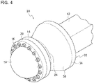
- Fig. 4 is a schematic perspective view illustrating the configuration of a pressure vessel 30.
- Fig. 5 is a schematic side view illustrating the configuration of the pressure vessel 30. Note that similar components are denoted by the same reference signs, and detailed description thereof is omitted.
- the pressure vessel 30 in the second embodiment differs from the pressure vessel 10 in the first embodiment by the configuration of a pressure-vessel-body connected portion 34 and a connecting portion 36 in a connecting member 32.
- the pressure-vessel-body connected portion 34 of the connecting member 32 is larger in outer shape than the body-flange connected portion 24, has a circular cross-sectional shape, and is formed in a cylindrical shape.
- the pressure-vessel-body connected portion 34 may be formed as a circular ring or the like, for example.
- the pressure-vessel-body connected portion 34 is formed such that one end side of the pressure vessel body can be inserted and fitted in it.
- the pressure-vessel-body connected portion 34 can be shaped into a ring with an outer diameter of approximately 600 mm and a thickness of approximately 90 mm, for example.
- the pressure-vessel-body connected portion 34 is joined to the pressure vessel body 12 by welding or the like.
- the connecting portion 36 of the connecting member 32 connects the body-flange connected portion 24 and the pressure-vessel-body connected portion 34 to each other and is formed in a cylindrical shape with a shape changing to be gradually smaller from the pressure-vessel-body connected portion 34 toward the body-flange connected portion 24. Since the body-flange connected portion 24 has a circular cross-sectional shape and the pressure-vessel-body connected portion 34 has a circular cross-sectional shape, the coupling portion 36 may be formed in a conical, semi-spherical, or semi-ellipsoidal shape.
- the connecting portion 36 can be formed to have an inner diameter of approximately 550 mm on the pressure-vessel-body connected portion side, an inner diameter of approximately 450 mm on the body-flange connected portion side, a width of 200 mm in the longitudinal direction, and a thickness of approximately 30 mm, for example. Since the connecting portion 36 is formed in a conical, semi-spherical, or semi-ellipsoidal shape, the shape of the connecting portion 36 is simple. This makes it easy to form the connecting member 32.
- the connecting portion 36 may be formed integrally with the body-flange connected portion 24 and the pressure-vessel-body connected portion 34, or formed as a separate body and then joined to the body-flange connected portion 24 and the pressure-vessel-body connected portion 34 by welding or the like. Note that the material and the forming method of the connecting member 32 are similar to those of the connecting member 22 in the first embodiment, and detailed description thereof is therefore omitted.
- the connecting member is such that the body-flange connected portion and the pressure-vessel-body connected portion have circular cross-sectional shapes and the connecting portion is formed in a conical, semi-spherical, or semi-ellipsoidal shape.
- Fig. 6 is a schematic perspective view illustrating the configuration of a pressure vessel 40.
- Fig. 7 is a schematic side view illustrating the configuration of the pressure vessel 40. Note that similar components are denoted by the same reference signs, and detailed description thereof is omitted.
- the pressure vessel 40 in the third embodiment differs from the pressure vessel 10 in the first embodiment by the configuration of a body-flange connected portion 44 in a connecting member 42.
- the body-flange connected portion 44 of the connecting member 42 is connected to the body flange 14, has a circular cross-sectional shape, and is formed in a cylindrical shape.
- the body-flange connected portion 44 is formed to extend in the longitudinal direction of the pressure vessel body 12.
- the body-flange connected portion 44 is shaped into, for example, a circular tube extending in the longitudinal direction of the pressure vessel body 12. In this way, a space to dispose components and so on can be provided inside the body-flange connected portion 44.
- the body-flange connected portion 44 can be formed to extend in the longitudinal direction of the pressure vessel body 12 to provide a space to dispose components and so on.
- the length of the connecting member 42 may be approximately 400 mm, for example. Note that the material and the forming method of the connecting member 42 are similar to those of the connecting member 22 in the first embodiment, and detailed description thereof is therefore omitted.
- the body-flange connected portion of the connecting member is formed to extend in the longitudinal direction of the pressure vessel body.
- the present disclosure can make a pressure vessel lighter and make the manufacturing cost of a pressure vessel lower and is therefore useful for reactors, heat exchangers, and the like.
Landscapes
- Engineering & Computer Science (AREA)
- General Engineering & Computer Science (AREA)
- Physics & Mathematics (AREA)
- Mechanical Engineering (AREA)
- Thermal Sciences (AREA)
- Plasma & Fusion (AREA)
- High Energy & Nuclear Physics (AREA)
- Pressure Vessels And Lids Thereof (AREA)
- Filling Or Discharging Of Gas Storage Vessels (AREA)
Abstract
Description
- The present disclosure relates to a pressure vessel. The present application is a divisional application of
European patent application no. 17873055.2 - In pressure vessels such as reactors and heat exchangers, heat exchange is performed between a primary fluid and a secondary fluid for production of a reacted product, heating, cooling, and so on. A pressure vessel configured as a heat exchanger is described in Published
Japanese Translation of PCT International Application No. 2012-525562 - [PTL 1] Patent Literature 1: Published
Japanese Translation of PCT International Application No. 2012-525562 - Meanwhile,
Fig. 1 is a schematic view illustrating the configuration of aconventional pressure vessel 100. Theconventional pressure vessel 100, which is a rector, a heat exchanger, or the like, includes ashell part 102 provided with flow channels through which fluids are caused to flow, and ashell flange 104 provided on at least one end side of theshell part 102 in the longitudinal direction. Theshell part 102 has a rectangular cross-sectional shape. Theshell flange 104 has a circular cross-sectional shape. For example, theshell flange 104 is fastened to alid flange 108 of alid member 106 with fastening members such asbolts 110 so as to be openable and closable. The one end side of theshell part 102 is inserted and fitted in theshell flange 104 and joined to theshell flange 104 by welding or the like. - A fastening load caused when the
shell flange 104 and thelid flange 108 are fastened with fastening members such as thebolts 110 is applied to the portion of theshell part 102 fitted in theshell flange 104. Since theshell part 102 and theshell flange 104 have different cross-sectional shapes, the cross-sectional shape is discontinuous between them. Thus, edges and the like of theshell part 102 may possibly receive an excessive load resulting from the fastening load. More specifically, corners and the like of the fitted portion of theshell part 102 on the one end side inserted and fitted in theshell flange 104 may possibly receive an excessive load. Then, to reduce the application of the fastening load to theshell part 102, the thickness of theshell flange 104 needs be large, which may increase the manufacturing cost of thepressure vessel 100. - In view of this, an object of the present disclosure is to provide a pressure vessel whose manufacturing cost can be made lower.
- A pressure vessel according to the present disclosure includes a pressure vessel body provided with a flow channel through which a fluid is caused to flow, having a rectangular cross-sectional shape, and formed to extend in a direction of flow of the fluid, a body flange provided at at least one end side of the pressure vessel body in a longitudinal direction and having a circular cross-sectional shape, and a connecting member connecting the pressure vessel body and the body flange to each other, and the connecting member has a body-flange connected portion connected to the body flange, having a circular cross-sectional shape, and formed in a cylindrical shape, a pressure-vessel-body connected portion connected to the pressure vessel body, being larger in outer shape than the body-flange connected portion, and formed in a cylindrical shape, and a connecting portion connecting the body-flange connected portion and the pressure-vessel-body connected portion to each other and formed in a cylindrical shape with a shape changing to be gradually smaller from the pressure-vessel-body connected portion toward the body-flange connected portion.
- The pressure vessel according to the present disclosure may be such that the pressure-vessel-body connected portion has a rectangular cross-sectional shape, and the connecting portion is formed such that one end thereof connected to the pressure-vessel-body connected portion is formed in a rectangular shape while another end thereof connected to the body-flange connected portion is formed in a circular shape and a cross-sectional shape of the connecting portion gradually changes from the rectangular shape into the circular shape from the one end, connected to the pressure-vessel-body connected portion, toward the other end, connected to the body-flange connected portion.
- The pressure vessel according to the present disclosure may be such that the pressure-vessel-body connected portion has a circular cross-sectional shape, and the connecting portion is formed in a conical, semi-spherical, or semi-ellipsoidal shape.
- The pressure vessel according to the present disclosure may be such that the body-flange connected portion is formed to extend in the longitudinal direction of the pressure vessel body.
- In the pressure vessel with the above configuration, the pressure vessel body does not need to be directly mounted to the body flange. Hence, when the body flange is fastened with fastening members such as bolts, it is possible to reduce the application of the fastening load to the pressure vessel. Accordingly, the thickness of the body flange can be smaller and therefore the manufacturing cost of the pressure vessel can be lower.
-
- [
Fig. 1 ]
Fig. 1 is a schematic view illustrating the configuration of a conventional pressure vessel. - [
Fig. 2 ]
Fig. 2 is a schematic perspective view illustrating the configuration of a pressure vessel in a first embodiment of the present disclosure. - [
Fig. 3 ]
Fig. 3 is a schematic side view illustrating the configuration of the pressure vessel in the first embodiment of the present disclosure. - [
Fig. 4 ]
Fig. 4 is a schematic perspective view illustrating the configuration of a pressure vessel in a second embodiment of the present disclosure. - [
Fig. 5 ]
Fig. 5 is a schematic side view illustrating the configuration of the pressure vessel in the second embodiment of the present disclosure. - [
Fig. 6 ]
Fig. 6 is a schematic perspective view illustrating the configuration of a pressure vessel in a third embodiment of the present disclosure. - [
Fig. 7 ]
Fig. 7 is a schematic side view illustrating the configuration of the pressure vessel in the third embodiment of the present disclosure. - Embodiments of the present disclosure will be described below in detail by using drawings.
- A first embodiment of the present disclosure will be described in detail by using drawings.
Fig. 2 is a schematic perspective view illustrating the configuration of apressure vessel 10.Fig. 3 is a schematic side view illustrating the configuration of thepressure vessel 10. Thepressure vessel 10 is configured as a reactor, a heat exchanger, or the like, for example. Thepressure vessel 10 includes apressure vessel body 12 and abody flange 14 provided at at least one end side of thepressure vessel body 12 in the longitudinal direction. - The
pressure vessel body 12 is provided with a flow channel through which a fluid is caused to flow, has a rectangular cross-sectional shape, and is formed to extend in the direction of flow of the fluid. Thepressure vessel body 12 is formed is a cuboidal shape or the like, for example. Thepressure vessel body 12 is made of stainless steel, a Ni (nickel) alloy, low-alloy steel, carbon steel, or the like. Thepressure vessel body 12 has a flow channel (not illustrated) through which a fluid is caused to flow. The flow channel may be provided as a single flow channel or provided as a plurality of flow channels . The flow channel may be formed along the longitudinal direction of thepressure vessel body 12. The flow channel may be formed in a straight shape or formed in a meandering shape. In-channel components such as catalyst members and fins may be disposed in the flow channel. A fluid inlet-outlet port (not illustrated) may be provided in one end surface of thepressure vessel body 12 in the longitudinal direction, the fluid inlet-outlet port being a port which connects with the flow channel and through which the fluid is caused to flow in or out. - The
body flange 14 is provided at at least one end side of thepressure vessel body 12 in the longitudinal direction. Thebody flange 14 is provided separated from the one end side of thepressure vessel body 12. Thebody flange 14 has a circular cross-sectional shape. Thebody flange 14 can be formed by using a weld neck flange (butt-welded flange). The opening portion of thebody flange 14 may be formed in a circular shape or the like. In the periphery of thebody flange 14, thebody flange 14 has fastening holes for fastening it with fastening members such asbolts 16. Thebody flange 14 is made of stainless steel, a Ni alloy, low-alloy steel, carbon steel, or the like. - The
pressure vessel 10 may include alid member 18. Thelid member 18 is formed in a dome shape or the like. Thelid member 18 is provided with alid flange 20. Thelid flange 20 has a circular cross-sectional shape. Thelid flange 20 is joined to thelid member 18 by welding or the like. In the periphery of thelid flange 20, thelid flange 20 has fastening holes for fastening it to thebody flange 14 with fastening members such as thebolts 16. Thelid member 18 and thelid flange 20 are made of stainless steel, a Ni alloy, low-alloy steel, carbon steel, or the like. - The
pressure vessel 10 may include an opening and closing structure having the above-describedbody flange 14 andlid flange 20. With this opening and closing structure, inspection, maintenance, and so on of thepressure vessel 10 can be performed in an opened state. Note that thepressure vessel 10 may alternatively include an opening and closing structure formed of a combination of thebody flange 14 and a flange obtained by mounting a different structure in place of thelid flange 20. - The
pressure vessel 10 includes a connectingmember 22 that connects thepressure vessel body 12 and thebody flange 14 to each other. The connectingmember 22 is provided between thepressure vessel body 12 and thebody flange 14. The connectingmember 22 has the function of connecting thepressure vessel body 12 and thebody flange 14 to each other. The connectingmember 22 has a body-flange connectedportion 24 connected to thebody flange 14, a pressure-vessel-body connectedportion 26 connected to thepressure vessel body 12, and a connectingportion 28 connecting the body-flange connectedportion 24 and the pressure-vessel-body connectedportion 26 to each other. The length of the connectingmember 22 may be approximately 160 mm, for example. - Since the connecting
member 22 is mounted between thepressure vessel body 12 and thebody flange 14, thepressure vessel body 12 can avoid being directly mounted to thebody flange 14. Hence, when thebody flange 14 is fastened with fastening members such as thebolts 16, it is possible to reduce the application of the fastening load to thepressure vessel body 12. - Moreover, since the
pressure vessel body 12 is not directly mounted to thebody flange 14, the thickness of thebody flange 14 can be smaller. For example, in the case where thepressure vessel 10 is subjected to an internal pressure of 2 MPa at 400°C, the thickness of a conventional flange needs to be approximately 90 mm. However, with the connectingmember 22 provided, the thickness of thebody flange 14 can be approximately 60 mm. Since the thickness of thebody flange 14 can be smaller as described above, it is possible to employ a standard flange specified in, for example, JIS or the like. Also, since the thickness of thebody flange 14 can be smaller, the manufacturing cost of thepressure vessel 10 can be reduced. The connectingmember 22 is made of stainless steel, a Ni alloy, low-alloy steel, carbon steel, or the like. Thecoupling member 22 may be made of the same material as thepressure vessel body 12 and thebody flange 14. The connectingmember 22 can be formed by common machining processes for metallic materials such as cutting and plastic working. - The body-flange connected
portion 24 is connected to thebody flange 14, has a circular cross-sectional shape, and is formed in a cylindrical shape. The body-flange connectedportion 24 may be partly inserted and fitted in the opening portion of thebody flange 14. The body-flange connectedportion 24 is joined to thebody flange 14 by welding or the like. Since the body-flange connectedportion 24 and thebody flange 14 have circular cross-sectional shapes, the cross-sectional shape is continuous between them. This prevents excessive application of the fastening load to the body-flange connectedportion 24 when thebody flange 14 is fastened with fastening members such as thebolts 16. - The pressure-vessel-body connected
portion 26 is connected to thepressure vessel body 12, larger in outer shape than the body-flange connectedportion 24, and formed in a cylindrical shape. The pressure-vessel-body connectedportion 26 is formed such that one end side of thepressure vessel body 12 can be inserted and fitted in it. The pressure-vessel-body connectedportion 26 is formed to be larger in outer shape than the body-flange connectedportion 24. The pressure-vessel-body connectedportion 26 is joined to thepressure vessel body 12 by welding or the like. - The pressure-vessel-body connected
portion 26 may be shaped into a rectangular tube. In the case where the pressure-vessel-body connectedportion 26 is shaped into a rectangular tube, the pressure-vessel-body connectedportion 26 and thepressure vessel body 12 have rectangular cross-sectional shapes, and the cross-sectional shape is therefore continuous between them. This alleviates the application of stress to thepressure vessel body 12 and the pressure-vessel-body connectedportion 26. The pressure-vessel-body connectedportion 26 may be formed as a rectangular plate provided with a rectangular hole or the like, for example. - The connecting
portion 28 connects the body-flange connectedportion 24 and the pressure-vessel-body connectedportion 26 to each other and is formed in a cylindrical shape with a shape changing to be gradually smaller from the pressure-vessel-body connectedportion 26 toward the body-flange connectedportion 24. For example, in the case where the body-flange connectedportion 24 is shaped into a circular tube and the pressure-vessel-body connectedportion 26 is shaped into a rectangular tube, the connectingportion 28 may be formed in a cylindrical shape with a shape changing to be gradually smaller while shifting from a rectangular tubular shape into a circular tubular shape from the pressure-vessel-body connectedportion 26 toward the body-flange connectedportion 24. In other words, the connectingportion 28 may be formed such that one end thereof connected to the pressure-vessel-body connectedportion 26 is formed in a rectangular shape while the other end thereof, connected to the body-flange connectedportion 24, is formed in a circular shape, and the cross-sectional shape gradually changes from the rectangular shape into the circular shape from the one end, connected to the pressure-vessel-body connectedportion 26, toward the other end, connected to the body-flange connectedportion 24. The connectingportion 28 may be formed integrally with the body-flange connectedportion 24 and the pressure-vessel-body connectedportion 26, or formed as a separate body and then joined to the body-flange connectedportion 24 and the pressure-vessel-body connectedportion 26 by welding or the like. - Note that the pressure-vessel-body connected portion may be smaller in outer shape than the body-flange connected portion and formed in a cylindrical shape. In this case, the connecting portion connects the body-flange connected portion and the pressure-vessel-body connected portion to each other and is formed in a cylindrical shape with a shape changing to be gradually larger from the pressure-vessel-body connected portion toward the body-flange connected portion. For example, in the case where the body-flange connected portion is shaped into a circular tube and the pressure-vessel-body connected portion is shaped into a rectangular tube, the connecting portion may be formed in a cylindrical shape with a shape changing to be gradually larger while shifting from a rectangular tubular shape into a circular tubular shape from the pressure-vessel-body connected portion toward the body-flange connected portion.
- In the pressure vessel with the above configuration, a connecting member is mounted between its pressure vessel body and body flange and therefore the pressure vessel body does not need to be directly mounted to the body flange. Hence, when the body flange is fastened with fastening members such as bolts, it is possible to reduce the application of the fastening load to the pressure vessel. Accordingly, the thickness of the body flange can be smaller and therefore the pressure vessel can be lighter and the manufacturing cost of the pressure vessel can be lower.
- Next, a second embodiment of the present disclosure will be described in detail by using drawings .
Fig. 4 is a schematic perspective view illustrating the configuration of apressure vessel 30.Fig. 5 is a schematic side view illustrating the configuration of thepressure vessel 30. Note that similar components are denoted by the same reference signs, and detailed description thereof is omitted. Thepressure vessel 30 in the second embodiment differs from thepressure vessel 10 in the first embodiment by the configuration of a pressure-vessel-body connectedportion 34 and a connectingportion 36 in a connectingmember 32. - The pressure-vessel-body connected
portion 34 of the connectingmember 32 is larger in outer shape than the body-flange connectedportion 24, has a circular cross-sectional shape, and is formed in a cylindrical shape. The pressure-vessel-body connectedportion 34 may be formed as a circular ring or the like, for example. The pressure-vessel-body connectedportion 34 is formed such that one end side of the pressure vessel body can be inserted and fitted in it. The pressure-vessel-body connectedportion 34 can be shaped into a ring with an outer diameter of approximately 600 mm and a thickness of approximately 90 mm, for example. The pressure-vessel-body connectedportion 34 is joined to thepressure vessel body 12 by welding or the like. - The connecting
portion 36 of the connectingmember 32 connects the body-flange connectedportion 24 and the pressure-vessel-body connectedportion 34 to each other and is formed in a cylindrical shape with a shape changing to be gradually smaller from the pressure-vessel-body connectedportion 34 toward the body-flange connectedportion 24. Since the body-flange connectedportion 24 has a circular cross-sectional shape and the pressure-vessel-body connectedportion 34 has a circular cross-sectional shape, thecoupling portion 36 may be formed in a conical, semi-spherical, or semi-ellipsoidal shape. The connectingportion 36 can be formed to have an inner diameter of approximately 550 mm on the pressure-vessel-body connected portion side, an inner diameter of approximately 450 mm on the body-flange connected portion side, a width of 200 mm in the longitudinal direction, and a thickness of approximately 30 mm, for example. Since the connectingportion 36 is formed in a conical, semi-spherical, or semi-ellipsoidal shape, the shape of the connectingportion 36 is simple. This makes it easy to form the connectingmember 32. The connectingportion 36 may be formed integrally with the body-flange connectedportion 24 and the pressure-vessel-body connectedportion 34, or formed as a separate body and then joined to the body-flange connectedportion 24 and the pressure-vessel-body connectedportion 34 by welding or the like. Note that the material and the forming method of the connectingmember 32 are similar to those of the connectingmember 22 in the first embodiment, and detailed description thereof is therefore omitted. - In the above configuration, the connecting member is such that the body-flange connected portion and the pressure-vessel-body connected portion have circular cross-sectional shapes and the connecting portion is formed in a conical, semi-spherical, or semi-ellipsoidal shape. Thus, in addition to achieving the effects of the first embodiment, it is possible to form the connecting member easily.
- Next, a third embodiment of the present disclosure will be described in detail by using drawings.
Fig. 6 is a schematic perspective view illustrating the configuration of apressure vessel 40.Fig. 7 is a schematic side view illustrating the configuration of thepressure vessel 40. Note that similar components are denoted by the same reference signs, and detailed description thereof is omitted. Thepressure vessel 40 in the third embodiment differs from thepressure vessel 10 in the first embodiment by the configuration of a body-flange connectedportion 44 in a connectingmember 42. - The body-flange connected
portion 44 of the connectingmember 42 is connected to thebody flange 14, has a circular cross-sectional shape, and is formed in a cylindrical shape. The body-flange connectedportion 44 is formed to extend in the longitudinal direction of thepressure vessel body 12. The body-flange connectedportion 44 is shaped into, for example, a circular tube extending in the longitudinal direction of thepressure vessel body 12. In this way, a space to dispose components and so on can be provided inside the body-flange connectedportion 44. Thus, the body-flange connectedportion 44 can be formed to extend in the longitudinal direction of thepressure vessel body 12 to provide a space to dispose components and so on. The length of the connectingmember 42 may be approximately 400 mm, for example. Note that the material and the forming method of the connectingmember 42 are similar to those of the connectingmember 22 in the first embodiment, and detailed description thereof is therefore omitted. - In the above configuration, the body-flange connected portion of the connecting member is formed to extend in the longitudinal direction of the pressure vessel body. Thus, in addition to achieving the effects of the first embodiment, it is possible to dispose components and so on in the body-flange connected portion.
- The present disclosure can make a pressure vessel lighter and make the manufacturing cost of a pressure vessel lower and is therefore useful for reactors, heat exchangers, and the like.
- The specification discloses the inventions defined by the following clauses:
- [Clause 1] A pressure vessel comprising:
- a pressure vessel body provided with a flow channel through which a fluid is caused to flow, having a rectangular cross-sectional shape, and formed to extend in a direction of flow of the fluid;
- a body flange provided at at least one end side of the pressure vessel body in a longitudinal direction and having a circular cross-sectional shape; and
- a connecting member connecting the pressure vessel body and the body flange to each other,
- wherein the connecting member has
- a body-flange connected portion connected to the body flange, having a circular cross-sectional shape, and formed in a cylindrical shape,
- a pressure-vessel-body connected portion connected to the pressure vessel body, being larger in outer shape than the body-flange connected portion, and formed in a cylindrical shape, and
- a connecting portion connecting the body-flange connected portion and the pressure-vessel-body connected portion to each other and formed in a cylindrical shape with a shape changing to be gradually smaller from the pressure-vessel-body connected portion toward the body-flange connected portion.
- [Clause 2] The pressure vessel according to Clause 1, wherein
- the pressure-vessel-body connected portion has a rectangular cross-sectional shape, and
- the connecting portion is formed such that one end thereof connected to the pressure-vessel-body connected portion is formed in a rectangular shape while another end thereof connected to the body-flange connected portion is formed in a circular shape and a cross-sectional shape of the connecting portion gradually changes from the rectangular shape into the circular shape from the one end, connected to the pressure-vessel-body connected portion, toward the other end, connected to the body-flange connected portion.
- [Clause 3] The pressure vessel according to Clause 1, wherein
- the pressure-vessel-body connected portion has a circular cross-sectional shape, and
- the connecting portion is formed in a conical, semi-spherical, or semi-ellipsoidal shape.
- [Clause 4] The pressure vessel according to Clause 1, wherein the body-flange connected portion is formed to extend in the longitudinal direction of the pressure vessel body.
- [Clause 5] The pressure vessel according to Clause 2, wherein the body-flange connected portion is formed to extend in the longitudinal direction of the pressure vessel body.
- [Clause 6] The pressure vessel according to
Clause 3, wherein the body-flange connected portion is formed to extend in the longitudinal direction of the pressure vessel body.
Claims (4)
- A pressure vessel comprising:a pressure vessel body provided with a flow channel through which a fluid is caused to flow, having a rectangular cross-sectional shape, and formed to extend in a longitudinal direction;a body flange provided at at least one end side of the pressure vessel body in the longitudinal direction and having a circular cross-sectional shape; anda connecting member connecting the pressure vessel body and the body flange to each other,wherein the connecting member hasa body-flange connected portion connected to the body flange, having a circular cross-sectional shape, and formed in a cylindrical shape,a pressure-vessel-body connected portion connected to the pressure vessel body, being larger in outer shape than the body-flange connected portion, and formed in a cylindrical shape, anda connecting portion connecting the body-flange connected portion and the pressure-vessel-body connected portion to each other and formed in a cylindrical shape with a shape changing to be gradually smaller from the pressure-vessel-body connected portion toward the body-flange connected portion,the pressure-vessel-body connected portion has a rectangular cross-sectional shape, andthe connecting portion is formed such that one end thereof connected to the pressure-vessel-body connected portion is formed in a rectangular shape while another end thereof connected to the body-flange connected portion is formed in a circular shape and a cross-sectional shape of the connecting portion gradually changes from the rectangular shape into the circular shape from the one end, connected to the pressure-vessel-body connected portion, toward the other end, connected to the body-flange connected portion.
- A pressure vessel comprising:a pressure vessel body provided with a flow channel through which a fluid is caused to flow, having a rectangular cross-sectional shape, and formed to extend in a longitudinal direction;a body flange provided at at least one end side of the pressure vessel body in the longitudinal direction and having a circular cross-sectional shape; anda connecting member connecting the pressure vessel body and the body flange to each other,wherein the connecting member hasa body-flange connected portion connected to the body flange, having a circular cross-sectional shape, and formed in a cylindrical shape,a pressure-vessel-body connected portion connected to the pressure vessel body, being smaller in outer shape than the body-flange connected portion, and formed in a cylindrical shape, anda connecting portion connecting the body-flange connected portion and the pressure-vessel-body connected portion to each other and formed in a cylindrical shape with a shape changing to be gradually larger from the pressure-vessel-body connected portion toward the body-flange connected portion.
- The pressure vessel according to claim 1 or 2, wherein the body-flange connected portion is formed to extend in the longitudinal direction of the pressure vessel body.
- The pressure vessel according to claim 3, wherein the body-flange connected portion is provided with a space to dispose a component.
Applications Claiming Priority (3)
| Application Number | Priority Date | Filing Date | Title |
|---|---|---|---|
| JP2016228851A JP7035308B2 (en) | 2016-11-25 | 2016-11-25 | Pressure vessel |
| EP17873055.2A EP3546877B1 (en) | 2016-11-25 | 2017-11-21 | Pressure container |
| PCT/JP2017/041813 WO2018097128A1 (en) | 2016-11-25 | 2017-11-21 | Pressure container |
Related Parent Applications (2)
| Application Number | Title | Priority Date | Filing Date |
|---|---|---|---|
| EP17873055.2A Division EP3546877B1 (en) | 2016-11-25 | 2017-11-21 | Pressure container |
| EP17873055.2A Division-Into EP3546877B1 (en) | 2016-11-25 | 2017-11-21 | Pressure container |
Publications (2)
| Publication Number | Publication Date |
|---|---|
| EP3974761A1 true EP3974761A1 (en) | 2022-03-30 |
| EP3974761B1 EP3974761B1 (en) | 2024-02-28 |
Family
ID=62195851
Family Applications (2)
| Application Number | Title | Priority Date | Filing Date |
|---|---|---|---|
| EP17873055.2A Active EP3546877B1 (en) | 2016-11-25 | 2017-11-21 | Pressure container |
| EP21208633.4A Active EP3974761B1 (en) | 2016-11-25 | 2017-11-21 | Pressure vessel |
Family Applications Before (1)
| Application Number | Title | Priority Date | Filing Date |
|---|---|---|---|
| EP17873055.2A Active EP3546877B1 (en) | 2016-11-25 | 2017-11-21 | Pressure container |
Country Status (7)
| Country | Link |
|---|---|
| US (1) | US11177046B2 (en) |
| EP (2) | EP3546877B1 (en) |
| JP (1) | JP7035308B2 (en) |
| CN (1) | CN109906352B (en) |
| CA (1) | CA3042875C (en) |
| DK (1) | DK3546877T3 (en) |
| WO (1) | WO2018097128A1 (en) |
Citations (4)
| Publication number | Priority date | Publication date | Assignee | Title |
|---|---|---|---|---|
| JP2002107091A (en) * | 2000-09-29 | 2002-04-10 | Toyo Radiator Co Ltd | Heat exchanger |
| US20070295479A1 (en) * | 2006-06-27 | 2007-12-27 | Tranter Phe, Inc. | Plate-type heat exchanger |
| CN101576029A (en) * | 2009-06-09 | 2009-11-11 | 锦州美联桥汽车部件有限公司 | Exhaust gas recirculation cooler for medium and heavy-duty vehicle with ridge ring |
| JP2014001830A (en) * | 2012-06-20 | 2014-01-09 | Kobe Steel Ltd | Pressure container |
Family Cites Families (20)
| Publication number | Priority date | Publication date | Assignee | Title |
|---|---|---|---|---|
| DE59709173D1 (en) * | 1996-05-23 | 2003-02-27 | Scambia Ind Developments Ag Sc | Exhaust manifold with catalytic converter |
| JP3948638B2 (en) * | 1997-05-14 | 2007-07-25 | 臼井国際産業株式会社 | EGR gas cooling device |
| US6273180B1 (en) | 1998-12-23 | 2001-08-14 | L'air Liquide, Societe Anonyme Pour L'etude Et L'eploitation Des Procedes Georges Claude | Heat exchanger for preheating an oxidizing gas |
| JP2001241872A (en) | 1999-12-24 | 2001-09-07 | Maruyasu Industries Co Ltd | Multitubular heat exchanger |
| JP3956097B2 (en) | 2002-01-07 | 2007-08-08 | 株式会社デンソー | Exhaust heat exchanger |
| US7077190B2 (en) * | 2001-07-10 | 2006-07-18 | Denso Corporation | Exhaust gas heat exchanger |
| FR2933178A1 (en) | 2008-06-26 | 2010-01-01 | Valeo Systemes Thermiques | HEAT EXCHANGER AND CARTER FOR THE EXCHANGER |
| EP2165755A1 (en) | 2008-09-23 | 2010-03-24 | Methanol Casale S.A. | Heat exchanger with radially arranged elements for isothermal chemical reactors |
| JP5272642B2 (en) | 2008-10-21 | 2013-08-28 | 新日鐵住金株式会社 | Metal hollow joint for circular steel pipe, method for producing metal hollow joint, and circular steel pipe member using the same |
| US20120103578A1 (en) | 2009-04-29 | 2012-05-03 | Westinghouse Electric Company Llc | Modular plate and shell heat exchanger |
| US9285172B2 (en) | 2009-04-29 | 2016-03-15 | Westinghouse Electric Company Llc | Modular plate and shell heat exchanger |
| GB0918738D0 (en) | 2009-10-26 | 2009-12-09 | Compactgtl Plc | Reactor with channels |
| JP5396580B2 (en) | 2011-11-01 | 2014-01-22 | 株式会社サクラプロリンク | Air heat exchanger with built-in cold / hot water coil |
| CN102721304B (en) | 2012-07-13 | 2013-11-27 | 甘肃蓝科石化高新装备股份有限公司 | Full-serial plate shell heat exchanger |
| WO2014152239A2 (en) | 2013-03-15 | 2014-09-25 | Thar Energy Llc | Countercurrent heat exchanger/reactor |
| CN103267434A (en) | 2013-05-23 | 2013-08-28 | 山东豪迈机械制造有限公司 | Detachable spiral winding heat exchanger |
| JP6356989B2 (en) | 2014-03-24 | 2018-07-11 | 住友精密工業株式会社 | Heat exchanger |
| JP2016109106A (en) | 2014-12-10 | 2016-06-20 | 株式会社深井製作所 | Exhaust emission control system |
| CN205505804U (en) * | 2015-12-01 | 2016-08-24 | 浙江驰捷动力系统有限公司 | Cooler |
| CN105582773B (en) | 2016-03-04 | 2017-07-11 | 河北科技大学 | A kind of industry or laboratory exhaust gas processing recovery heat exchanger |
-
2016
- 2016-11-25 JP JP2016228851A patent/JP7035308B2/en active Active
-
2017
- 2017-11-21 DK DK17873055.2T patent/DK3546877T3/en active
- 2017-11-21 WO PCT/JP2017/041813 patent/WO2018097128A1/en unknown
- 2017-11-21 EP EP17873055.2A patent/EP3546877B1/en active Active
- 2017-11-21 CA CA3042875A patent/CA3042875C/en active Active
- 2017-11-21 EP EP21208633.4A patent/EP3974761B1/en active Active
- 2017-11-21 CN CN201780068207.4A patent/CN109906352B/en active Active
-
2019
- 2019-05-07 US US16/405,474 patent/US11177046B2/en active Active
Patent Citations (4)
| Publication number | Priority date | Publication date | Assignee | Title |
|---|---|---|---|---|
| JP2002107091A (en) * | 2000-09-29 | 2002-04-10 | Toyo Radiator Co Ltd | Heat exchanger |
| US20070295479A1 (en) * | 2006-06-27 | 2007-12-27 | Tranter Phe, Inc. | Plate-type heat exchanger |
| CN101576029A (en) * | 2009-06-09 | 2009-11-11 | 锦州美联桥汽车部件有限公司 | Exhaust gas recirculation cooler for medium and heavy-duty vehicle with ridge ring |
| JP2014001830A (en) * | 2012-06-20 | 2014-01-09 | Kobe Steel Ltd | Pressure container |
Also Published As
| Publication number | Publication date |
|---|---|
| CA3042875A1 (en) | 2018-05-31 |
| EP3974761B1 (en) | 2024-02-28 |
| EP3546877A1 (en) | 2019-10-02 |
| DK3546877T3 (en) | 2022-03-21 |
| CA3042875C (en) | 2021-05-11 |
| JP2018084396A (en) | 2018-05-31 |
| EP3546877A4 (en) | 2020-06-17 |
| EP3546877B1 (en) | 2022-01-05 |
| WO2018097128A1 (en) | 2018-05-31 |
| CN109906352A (en) | 2019-06-18 |
| CN109906352B (en) | 2021-07-16 |
| JP7035308B2 (en) | 2022-03-15 |
| US11177046B2 (en) | 2021-11-16 |
| US20190267144A1 (en) | 2019-08-29 |
Similar Documents
| Publication | Publication Date | Title |
|---|---|---|
| US7413006B2 (en) | Header plate for use in a heat exchanger | |
| CN100501297C (en) | Heat pipe radiator and method for manufacturing same | |
| EP3974761B1 (en) | Pressure vessel | |
| WO2018070427A1 (en) | Thermal treatment device | |
| CN104457332B (en) | High-temperature-resistant heat exchanger | |
| US20180347527A1 (en) | Gasoline direct-injection rail | |
| EP3546874B1 (en) | Pressure container | |
| EP3527858B1 (en) | Pressure vessel | |
| EP2942589B1 (en) | Heat exchanger | |
| CN205370676U (en) | Stainless steel shell -and -tube oil cooler | |
| US6775909B2 (en) | Lining device for a plate heat exchanger | |
| EP2991757A1 (en) | Jacketed autoclave device for production of polyamides | |
| US9279357B2 (en) | Double-walled exhaust volume and corresponding manufacturing method | |
| CA2779323A1 (en) | Heat exchanger | |
| US11859916B2 (en) | Flow path member for heat exchanger, and heat exchanger | |
| EP3742100A1 (en) | Plate heat exchanger | |
| CN205837676U (en) | A kind of heat-transferring jacket |
Legal Events
| Date | Code | Title | Description |
|---|---|---|---|
| PUAI | Public reference made under article 153(3) epc to a published international application that has entered the european phase |
Free format text: ORIGINAL CODE: 0009012 |
|
| STAA | Information on the status of an ep patent application or granted ep patent |
Free format text: STATUS: REQUEST FOR EXAMINATION WAS MADE |
|
| 17P | Request for examination filed |
Effective date: 20211116 |
|
| AC | Divisional application: reference to earlier application |
Ref document number: 3546877 Country of ref document: EP Kind code of ref document: P |
|
| AK | Designated contracting states |
Kind code of ref document: A1 Designated state(s): AL AT BE BG CH CY CZ DE DK EE ES FI FR GB GR HR HU IE IS IT LI LT LU LV MC MK MT NL NO PL PT RO RS SE SI SK SM TR |
|
| STAA | Information on the status of an ep patent application or granted ep patent |
Free format text: STATUS: EXAMINATION IS IN PROGRESS |
|
| 17Q | First examination report despatched |
Effective date: 20220714 |
|
| GRAP | Despatch of communication of intention to grant a patent |
Free format text: ORIGINAL CODE: EPIDOSNIGR1 |
|
| STAA | Information on the status of an ep patent application or granted ep patent |
Free format text: STATUS: GRANT OF PATENT IS INTENDED |
|
| INTG | Intention to grant announced |
Effective date: 20230929 |
|
| GRAS | Grant fee paid |
Free format text: ORIGINAL CODE: EPIDOSNIGR3 |
|
| GRAA | (expected) grant |
Free format text: ORIGINAL CODE: 0009210 |
|
| STAA | Information on the status of an ep patent application or granted ep patent |
Free format text: STATUS: THE PATENT HAS BEEN GRANTED |
|
| AC | Divisional application: reference to earlier application |
Ref document number: 3546877 Country of ref document: EP Kind code of ref document: P |
|
| AK | Designated contracting states |
Kind code of ref document: B1 Designated state(s): AL AT BE BG CH CY CZ DE DK EE ES FI FR GB GR HR HU IE IS IT LI LT LU LV MC MK MT NL NO PL PT RO RS SE SI SK SM TR |
|
| REG | Reference to a national code |
Ref country code: GB Ref legal event code: FG4D |
|
| REG | Reference to a national code |
Ref country code: CH Ref legal event code: EP |
|
| REG | Reference to a national code |
Ref country code: DE Ref legal event code: R096 Ref document number: 602017079698 Country of ref document: DE |
|
| REG | Reference to a national code |
Ref country code: IE Ref legal event code: FG4D |
|
| REG | Reference to a national code |
Ref country code: LT Ref legal event code: MG9D |
|
| PG25 | Lapsed in a contracting state [announced via postgrant information from national office to epo] |
Ref country code: IS Free format text: LAPSE BECAUSE OF FAILURE TO SUBMIT A TRANSLATION OF THE DESCRIPTION OR TO PAY THE FEE WITHIN THE PRESCRIBED TIME-LIMIT Effective date: 20240628 |
|
| REG | Reference to a national code |
Ref country code: NL Ref legal event code: MP Effective date: 20240228 |
|
| PG25 | Lapsed in a contracting state [announced via postgrant information from national office to epo] |
Ref country code: LT Free format text: LAPSE BECAUSE OF FAILURE TO SUBMIT A TRANSLATION OF THE DESCRIPTION OR TO PAY THE FEE WITHIN THE PRESCRIBED TIME-LIMIT Effective date: 20240228 |
|
| PG25 | Lapsed in a contracting state [announced via postgrant information from national office to epo] |
Ref country code: GR Free format text: LAPSE BECAUSE OF FAILURE TO SUBMIT A TRANSLATION OF THE DESCRIPTION OR TO PAY THE FEE WITHIN THE PRESCRIBED TIME-LIMIT Effective date: 20240529 |
|
| PG25 | Lapsed in a contracting state [announced via postgrant information from national office to epo] |
Ref country code: RS Free format text: LAPSE BECAUSE OF FAILURE TO SUBMIT A TRANSLATION OF THE DESCRIPTION OR TO PAY THE FEE WITHIN THE PRESCRIBED TIME-LIMIT Effective date: 20240528 Ref country code: NL Free format text: LAPSE BECAUSE OF FAILURE TO SUBMIT A TRANSLATION OF THE DESCRIPTION OR TO PAY THE FEE WITHIN THE PRESCRIBED TIME-LIMIT Effective date: 20240228 Ref country code: HR Free format text: LAPSE BECAUSE OF FAILURE TO SUBMIT A TRANSLATION OF THE DESCRIPTION OR TO PAY THE FEE WITHIN THE PRESCRIBED TIME-LIMIT Effective date: 20240228 |
|
| PG25 | Lapsed in a contracting state [announced via postgrant information from national office to epo] |
Ref country code: ES Free format text: LAPSE BECAUSE OF FAILURE TO SUBMIT A TRANSLATION OF THE DESCRIPTION OR TO PAY THE FEE WITHIN THE PRESCRIBED TIME-LIMIT Effective date: 20240228 |
|
| PG25 | Lapsed in a contracting state [announced via postgrant information from national office to epo] |
Ref country code: RS Free format text: LAPSE BECAUSE OF FAILURE TO SUBMIT A TRANSLATION OF THE DESCRIPTION OR TO PAY THE FEE WITHIN THE PRESCRIBED TIME-LIMIT Effective date: 20240528 Ref country code: NO Free format text: LAPSE BECAUSE OF FAILURE TO SUBMIT A TRANSLATION OF THE DESCRIPTION OR TO PAY THE FEE WITHIN THE PRESCRIBED TIME-LIMIT Effective date: 20240528 Ref country code: NL Free format text: LAPSE BECAUSE OF FAILURE TO SUBMIT A TRANSLATION OF THE DESCRIPTION OR TO PAY THE FEE WITHIN THE PRESCRIBED TIME-LIMIT Effective date: 20240228 Ref country code: LT Free format text: LAPSE BECAUSE OF FAILURE TO SUBMIT A TRANSLATION OF THE DESCRIPTION OR TO PAY THE FEE WITHIN THE PRESCRIBED TIME-LIMIT Effective date: 20240228 Ref country code: IS Free format text: LAPSE BECAUSE OF FAILURE TO SUBMIT A TRANSLATION OF THE DESCRIPTION OR TO PAY THE FEE WITHIN THE PRESCRIBED TIME-LIMIT Effective date: 20240628 Ref country code: HR Free format text: LAPSE BECAUSE OF FAILURE TO SUBMIT A TRANSLATION OF THE DESCRIPTION OR TO PAY THE FEE WITHIN THE PRESCRIBED TIME-LIMIT Effective date: 20240228 Ref country code: GR Free format text: LAPSE BECAUSE OF FAILURE TO SUBMIT A TRANSLATION OF THE DESCRIPTION OR TO PAY THE FEE WITHIN THE PRESCRIBED TIME-LIMIT Effective date: 20240529 Ref country code: FI Free format text: LAPSE BECAUSE OF FAILURE TO SUBMIT A TRANSLATION OF THE DESCRIPTION OR TO PAY THE FEE WITHIN THE PRESCRIBED TIME-LIMIT Effective date: 20240228 Ref country code: ES Free format text: LAPSE BECAUSE OF FAILURE TO SUBMIT A TRANSLATION OF THE DESCRIPTION OR TO PAY THE FEE WITHIN THE PRESCRIBED TIME-LIMIT Effective date: 20240228 Ref country code: BG Free format text: LAPSE BECAUSE OF FAILURE TO SUBMIT A TRANSLATION OF THE DESCRIPTION OR TO PAY THE FEE WITHIN THE PRESCRIBED TIME-LIMIT Effective date: 20240228 |
|
| PG25 | Lapsed in a contracting state [announced via postgrant information from national office to epo] |
Ref country code: PT Free format text: LAPSE BECAUSE OF FAILURE TO SUBMIT A TRANSLATION OF THE DESCRIPTION OR TO PAY THE FEE WITHIN THE PRESCRIBED TIME-LIMIT Effective date: 20240628 Ref country code: PL Free format text: LAPSE BECAUSE OF FAILURE TO SUBMIT A TRANSLATION OF THE DESCRIPTION OR TO PAY THE FEE WITHIN THE PRESCRIBED TIME-LIMIT Effective date: 20240228 |
|
| REG | Reference to a national code |
Ref country code: AT Ref legal event code: MK05 Ref document number: 1661609 Country of ref document: AT Kind code of ref document: T Effective date: 20240228 |
|
| PG25 | Lapsed in a contracting state [announced via postgrant information from national office to epo] |
Ref country code: SE Free format text: LAPSE BECAUSE OF FAILURE TO SUBMIT A TRANSLATION OF THE DESCRIPTION OR TO PAY THE FEE WITHIN THE PRESCRIBED TIME-LIMIT Effective date: 20240228 Ref country code: PT Free format text: LAPSE BECAUSE OF FAILURE TO SUBMIT A TRANSLATION OF THE DESCRIPTION OR TO PAY THE FEE WITHIN THE PRESCRIBED TIME-LIMIT Effective date: 20240628 Ref country code: PL Free format text: LAPSE BECAUSE OF FAILURE TO SUBMIT A TRANSLATION OF THE DESCRIPTION OR TO PAY THE FEE WITHIN THE PRESCRIBED TIME-LIMIT Effective date: 20240228 Ref country code: LV Free format text: LAPSE BECAUSE OF FAILURE TO SUBMIT A TRANSLATION OF THE DESCRIPTION OR TO PAY THE FEE WITHIN THE PRESCRIBED TIME-LIMIT Effective date: 20240228 |