EP3974750A1 - Refrigerated device with enhanced defrost and condensate pan heater control - Google Patents
Refrigerated device with enhanced defrost and condensate pan heater control Download PDFInfo
- Publication number
- EP3974750A1 EP3974750A1 EP21198534.6A EP21198534A EP3974750A1 EP 3974750 A1 EP3974750 A1 EP 3974750A1 EP 21198534 A EP21198534 A EP 21198534A EP 3974750 A1 EP3974750 A1 EP 3974750A1
- Authority
- EP
- European Patent Office
- Prior art keywords
- water
- door
- amount
- compartment
- controller
- Prior art date
- Legal status (The legal status is an assumption and is not a legal conclusion. Google has not performed a legal analysis and makes no representation as to the accuracy of the status listed.)
- Pending
Links
- XLYOFNOQVPJJNP-UHFFFAOYSA-N water Substances O XLYOFNOQVPJJNP-UHFFFAOYSA-N 0.000 claims abstract description 56
- 238000005057 refrigeration Methods 0.000 claims abstract description 15
- 238000001816 cooling Methods 0.000 claims abstract description 8
- 239000012080 ambient air Substances 0.000 claims description 5
- 238000000034 method Methods 0.000 claims description 4
- 230000003213 activating effect Effects 0.000 claims description 3
- 230000000977 initiatory effect Effects 0.000 claims description 2
- 239000003570 air Substances 0.000 description 9
- 230000006870 function Effects 0.000 description 4
- 238000010438 heat treatment Methods 0.000 description 3
- 239000003507 refrigerant Substances 0.000 description 3
- 235000013305 food Nutrition 0.000 description 2
- 230000000153 supplemental effect Effects 0.000 description 2
- 238000010257 thawing Methods 0.000 description 2
- 230000004913 activation Effects 0.000 description 1
- 230000007423 decrease Effects 0.000 description 1
- 238000005485 electric heating Methods 0.000 description 1
- 238000001704 evaporation Methods 0.000 description 1
- 230000008020 evaporation Effects 0.000 description 1
- 238000012986 modification Methods 0.000 description 1
- 230000004048 modification Effects 0.000 description 1
- 238000012544 monitoring process Methods 0.000 description 1
- 239000007787 solid Substances 0.000 description 1
Images

Classifications
-
- F—MECHANICAL ENGINEERING; LIGHTING; HEATING; WEAPONS; BLASTING
- F25—REFRIGERATION OR COOLING; COMBINED HEATING AND REFRIGERATION SYSTEMS; HEAT PUMP SYSTEMS; MANUFACTURE OR STORAGE OF ICE; LIQUEFACTION SOLIDIFICATION OF GASES
- F25D—REFRIGERATORS; COLD ROOMS; ICE-BOXES; COOLING OR FREEZING APPARATUS NOT OTHERWISE PROVIDED FOR
- F25D21/00—Defrosting; Preventing frosting; Removing condensed or defrost water
- F25D21/06—Removing frost
- F25D21/08—Removing frost by electric heating
-
- F—MECHANICAL ENGINEERING; LIGHTING; HEATING; WEAPONS; BLASTING
- F25—REFRIGERATION OR COOLING; COMBINED HEATING AND REFRIGERATION SYSTEMS; HEAT PUMP SYSTEMS; MANUFACTURE OR STORAGE OF ICE; LIQUEFACTION SOLIDIFICATION OF GASES
- F25D—REFRIGERATORS; COLD ROOMS; ICE-BOXES; COOLING OR FREEZING APPARATUS NOT OTHERWISE PROVIDED FOR
- F25D21/00—Defrosting; Preventing frosting; Removing condensed or defrost water
- F25D21/14—Collecting or removing condensed and defrost water; Drip trays
-
- F—MECHANICAL ENGINEERING; LIGHTING; HEATING; WEAPONS; BLASTING
- F25—REFRIGERATION OR COOLING; COMBINED HEATING AND REFRIGERATION SYSTEMS; HEAT PUMP SYSTEMS; MANUFACTURE OR STORAGE OF ICE; LIQUEFACTION SOLIDIFICATION OF GASES
- F25D—REFRIGERATORS; COLD ROOMS; ICE-BOXES; COOLING OR FREEZING APPARATUS NOT OTHERWISE PROVIDED FOR
- F25D29/00—Arrangement or mounting of control or safety devices
-
- F—MECHANICAL ENGINEERING; LIGHTING; HEATING; WEAPONS; BLASTING
- F25—REFRIGERATION OR COOLING; COMBINED HEATING AND REFRIGERATION SYSTEMS; HEAT PUMP SYSTEMS; MANUFACTURE OR STORAGE OF ICE; LIQUEFACTION SOLIDIFICATION OF GASES
- F25D—REFRIGERATORS; COLD ROOMS; ICE-BOXES; COOLING OR FREEZING APPARATUS NOT OTHERWISE PROVIDED FOR
- F25D2321/00—Details or arrangements for defrosting; Preventing frosting; Removing condensed or defrost water, not provided for in other groups of this subclass
- F25D2321/14—Collecting condense or defrost water; Removing condense or defrost water
- F25D2321/141—Removal by evaporation
- F25D2321/1412—Removal by evaporation using condenser heat or heat of desuperheaters
-
- F—MECHANICAL ENGINEERING; LIGHTING; HEATING; WEAPONS; BLASTING
- F25—REFRIGERATION OR COOLING; COMBINED HEATING AND REFRIGERATION SYSTEMS; HEAT PUMP SYSTEMS; MANUFACTURE OR STORAGE OF ICE; LIQUEFACTION SOLIDIFICATION OF GASES
- F25D—REFRIGERATORS; COLD ROOMS; ICE-BOXES; COOLING OR FREEZING APPARATUS NOT OTHERWISE PROVIDED FOR
- F25D2321/00—Details or arrangements for defrosting; Preventing frosting; Removing condensed or defrost water, not provided for in other groups of this subclass
- F25D2321/14—Collecting condense or defrost water; Removing condense or defrost water
- F25D2321/141—Removal by evaporation
- F25D2321/1413—Removal by evaporation using heat from electric elements or using an electric field for enhancing removal
-
- F—MECHANICAL ENGINEERING; LIGHTING; HEATING; WEAPONS; BLASTING
- F25—REFRIGERATION OR COOLING; COMBINED HEATING AND REFRIGERATION SYSTEMS; HEAT PUMP SYSTEMS; MANUFACTURE OR STORAGE OF ICE; LIQUEFACTION SOLIDIFICATION OF GASES
- F25D—REFRIGERATORS; COLD ROOMS; ICE-BOXES; COOLING OR FREEZING APPARATUS NOT OTHERWISE PROVIDED FOR
- F25D2321/00—Details or arrangements for defrosting; Preventing frosting; Removing condensed or defrost water, not provided for in other groups of this subclass
- F25D2321/14—Collecting condense or defrost water; Removing condense or defrost water
- F25D2321/143—Collecting condense or defrost water; Removing condense or defrost water characterised by means to fix, clamp, or connect water pipes or evaporation trays
-
- F—MECHANICAL ENGINEERING; LIGHTING; HEATING; WEAPONS; BLASTING
- F25—REFRIGERATION OR COOLING; COMBINED HEATING AND REFRIGERATION SYSTEMS; HEAT PUMP SYSTEMS; MANUFACTURE OR STORAGE OF ICE; LIQUEFACTION SOLIDIFICATION OF GASES
- F25D—REFRIGERATORS; COLD ROOMS; ICE-BOXES; COOLING OR FREEZING APPARATUS NOT OTHERWISE PROVIDED FOR
- F25D2321/00—Details or arrangements for defrosting; Preventing frosting; Removing condensed or defrost water, not provided for in other groups of this subclass
- F25D2321/14—Collecting condense or defrost water; Removing condense or defrost water
- F25D2321/144—Collecting condense or defrost water; Removing condense or defrost water characterised by the construction of drip water collection pans
- F25D2321/1441—Collecting condense or defrost water; Removing condense or defrost water characterised by the construction of drip water collection pans inside a refrigerator
-
- F—MECHANICAL ENGINEERING; LIGHTING; HEATING; WEAPONS; BLASTING
- F25—REFRIGERATION OR COOLING; COMBINED HEATING AND REFRIGERATION SYSTEMS; HEAT PUMP SYSTEMS; MANUFACTURE OR STORAGE OF ICE; LIQUEFACTION SOLIDIFICATION OF GASES
- F25D—REFRIGERATORS; COLD ROOMS; ICE-BOXES; COOLING OR FREEZING APPARATUS NOT OTHERWISE PROVIDED FOR
- F25D2400/00—General features of, or devices for refrigerators, cold rooms, ice-boxes, or for cooling or freezing apparatus not covered by any other subclass
- F25D2400/04—Refrigerators with a horizontal mullion
-
- F—MECHANICAL ENGINEERING; LIGHTING; HEATING; WEAPONS; BLASTING
- F25—REFRIGERATION OR COOLING; COMBINED HEATING AND REFRIGERATION SYSTEMS; HEAT PUMP SYSTEMS; MANUFACTURE OR STORAGE OF ICE; LIQUEFACTION SOLIDIFICATION OF GASES
- F25D—REFRIGERATORS; COLD ROOMS; ICE-BOXES; COOLING OR FREEZING APPARATUS NOT OTHERWISE PROVIDED FOR
- F25D2700/00—Means for sensing or measuring; Sensors therefor
- F25D2700/02—Sensors detecting door opening
-
- F—MECHANICAL ENGINEERING; LIGHTING; HEATING; WEAPONS; BLASTING
- F25—REFRIGERATION OR COOLING; COMBINED HEATING AND REFRIGERATION SYSTEMS; HEAT PUMP SYSTEMS; MANUFACTURE OR STORAGE OF ICE; LIQUEFACTION SOLIDIFICATION OF GASES
- F25D—REFRIGERATORS; COLD ROOMS; ICE-BOXES; COOLING OR FREEZING APPARATUS NOT OTHERWISE PROVIDED FOR
- F25D2700/00—Means for sensing or measuring; Sensors therefor
- F25D2700/12—Sensors measuring the inside temperature
-
- F—MECHANICAL ENGINEERING; LIGHTING; HEATING; WEAPONS; BLASTING
- F25—REFRIGERATION OR COOLING; COMBINED HEATING AND REFRIGERATION SYSTEMS; HEAT PUMP SYSTEMS; MANUFACTURE OR STORAGE OF ICE; LIQUEFACTION SOLIDIFICATION OF GASES
- F25D—REFRIGERATORS; COLD ROOMS; ICE-BOXES; COOLING OR FREEZING APPARATUS NOT OTHERWISE PROVIDED FOR
- F25D2700/00—Means for sensing or measuring; Sensors therefor
- F25D2700/14—Sensors measuring the temperature outside the refrigerator or freezer
Definitions
- This application relates generally to refrigerated devices, such as refrigerator units and freezer units and, more specifically, to a control system for controlling defrost operations and/or a condensate pan heating element in such devices.
- Refrigerators are used in numerous settings, such as in a commercial setting or in a domestic setting. Typically, refrigerators are used to store and maintain food products by providing a cooled environment into which the products can be stored.
- Refrigeration systems typically include a refrigerated cabinet into which the food products are placed and a refrigeration assembly for cooling the air and products in the refrigerated cabinet.
- the refrigeration assembly often includes an evaporator assembly and a condenser assembly, each forming a portion of a refrigerant loop or circuit.
- a refrigerant is used to carry heat from air within the refrigerated cabinet to the ambient environment surrounding the refrigerated cabinet. The refrigerant absorbs heat in the evaporator assembly and then rejects the absorbed heat in the condenser assembly.
- Condensate on the evaporator coils may freeze, and such frost may accumulate on evaporator coils of the evaporator assembly, which decreases the efficiency of the refrigeration assembly.
- Defrosting cycles are typically utilized to remove the frost from the evaporator coils. Once frost has been removed from the evaporator coils, the defrost water or condensate may be transferred to a condensate pan where it may accumulate and be evaporated to ambient environment.
- a refrigerated device in one aspect, includes a compartment including an access door, and a door sensor for identifying an open condition of the access door.
- a refrigeration circuit is provided for cooling the compartment, the refrigeration circuit including an evaporator coil with an associated evaporator fan and a condenser with an associated condenser fan.
- a controller is configured to: (i) based upon an output of the door sensor, maintain a count of a number of door openings since a last defrost operation and (ii) approximate an amount of water that enters the compartment based at least in part on the count of the number of door openings.
- a refrigerated device in another aspect, includes a cooled compartment including an access door, and a door sensor for identifying an open condition of the access door.
- a refrigeration circuit is provided for cooling the compartment, the refrigeration circuit including an evaporator coil with an associated evaporator fan and a condenser with an associated condenser fan.
- At least one heat source is selectively activatable to provide heat.
- a controller is configured to approximate an amount of water that enters the compartment based at least in part on each of a count of door openings, a duration of each door opening, wherein the controller is further configured to selectively activate the heat source based at least in part upon the approximated amount of water.
- a refrigerated device in another aspect, includes a compartment including an access door, and a door sensor for identifying an open condition of the access door.
- a refrigeration circuit for cooling the compartment includes an evaporator coil with an associated evaporator fan and a condenser with an associated condenser fan.
- At least one heat source is selectively activatable to provide heat.
- a controller is configured to selectively activate the heat source, wherein the controller is configured to, based upon the output of the door sensor, count a number of door openings since a last defrost operation and to approximate an amount of water that enters the compartment based the count of door openings and to activate the heat source based at least in part upon the approximated amount of water.
- a method of controlling a defrost operation of a refrigerated device including a cooled compartment that is closeable by at least one door involves the steps of: approximating an amount of water that enters cooled compartment as a result of door open conditions; and initiating a defrost operation based at least in part upon the approximated amount of water.
- the step of approximating involves taking into account both a number of door openings and duration of such door openings.
- the step of approximating involves taking into account a dew point of an ambient environment in which the refrigerated device is located.
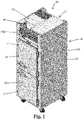
- Figs. 1-5 show a refrigerated device 10 (refrigerator and/or freezer) with a cabinet 12 defining one or more internal compartments 14 that are cooled and accessible via one or more doors 16. Door open sensors 17 are also shown.
- a refrigerated device 10 refrigerator and/or freezer
- a cabinet 12 defining one or more internal compartments 14 that are cooled and accessible via one or more doors 16.
- Door open sensors 17 are also shown.
- the refrigeration system 20 of the device is located at the top of the cabinet 12 and includes an evaporator unit or assembly 22 and a condenser unit or assembly 24.
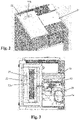
- the evaporator unit 22 includes an evaporator coil 22a and an air circulation fan 22b (shown schematically in Fig. 2 ), and a path for condensate to run to the condensate pan of the condenser unit 24.
- a heater 23, shown schematically, for defrosting of the evaporator coil is also shown.
- the condenser unit 24 includes the condenser coil 30, fan 32 and condensate pan 34, as well as the compressor 36.
- the floor 40 of the condenser unit includes three openings 42, 44 and 46 to the condensate pan 34.
- a hot gas loop 60 is provided in the condensate pan for condensate heating, and a supplemental electric heating element 62 is also provided in the condensate pan in order to further enhance the heating of the condensate and increase the evaporation rate.
- the device includes a controller 100 configured for controlling the various operations of the device, including cooling operations and defrost operations (involving activation of the heat sources 23 and 62).
- controller is intended to broadly encompass any circuit (e.g., solid state, application specific integrated circuit (ASIC), an electronic circuit, a combinational logic circuit, a field programmable gate array (FPGA)), processor(s) (e.g., shared, dedicated, or group - including hardware or software that executes code), software, firmware and/or other components, or a combination of some or all of the above, that carries out the control functions of the device or the control functions of any component thereof.
- ASIC application specific integrated circuit
- FPGA field programmable gate array
- the controller 100 is configured to selectively activate the heat sources 23 and 62.
- the controller 100 is configured to, based upon the output of the door sensors 17, a) maintain a count a number of door openings since a last defrost operation and b) approximate an amount of water that enters the compartment 14 based the count of door openings and c) selectively activate the heat sources 23 and 62 based at least in part upon the approximated amount of water.
- the approximated amount of water is determined in grains of water. A grain of water is approximately one drop, and there are 7,000 grains of water to one pound of water.
- the device includes at least one sensor 80 for detecting a temperature and a relative humidity of ambient air that surrounds the compartment 14.
- the controller 100 is configured to calculate a dew point temperature based on the temperature and the relative humidity of the ambient air.
- the controller 100 is configured to approximate the amount of water that enters the compartment 14 for each door open condition based at least in part upon the dew point temperature during each door open condition. Generally, the higher the dew point, the more moisture in the air entering the compartment, and the longer the door is open, the more air, and thus more water, that will enter.
- the controller 100 may further be configured to approximate the amount of water that enters the compartment 14 for each door open condition based at least in part upon a duration of each door open condition.
- the higher the dew point the more moisture in the air entering the compartment, and the longer the door is open, the more air, and thus more water, that will enter (e.g., longer door open condition means more ambient air entry and, thus, higher amount of water entry).
- the controller can be configured to approximate ambient air entry volume, and identify moisture content (e.g., grains) in that volume based upon the dew point.
- a psychrometric chart in the memory of the controller 100 may be used in the approximation, as such a chart includes information on the amount of water in air at various conditions.
- the controller is configured such that a next defrost operation, following the last defrost operation, is carried out by activating the heat source sooner if the approximated amount of water is high verses if the approximated amount of water is low.
- the controller 100 is configured such that a next defrost operation occurs upon the sooner of (i) a time since the last defrost operation reaching a set time threshold or (ii) the approximated grains of water reaching a set grains threshold.
- the controller is configured with various grains of water ranges that are used to set the threshold time for triggering the next defrost operation (e.g., for approximated grains less than X1, the set time threshold is ST1, for approximated grains between X1 and X2, the set time threshold is ST2, for approximated grains between X2 and X3, the set time threshold is ST3, for approximated grains between X3 and X4, the set time threshold is ST4, and so on, where X1 ⁇ X2 ⁇ X3 ⁇ X4 and ST1 > ST2 > ST3 > ST4).
- the set time threshold is ST1, for approximated grains between X1 and X2, the set time threshold is ST2, for approximated grains between X2 and X3, the set time threshold is ST3, for approximated grains between X3 and X4, the set time threshold is ST4, and so on, where X1 ⁇ X2 ⁇ X3 ⁇ X4 and ST1 > ST2 > ST3 > ST4).
- the set time threshold is ST
- the controller 100 is configured such that a next defrost operation occurs upon the sooner of (i) a trigger based upon one or more factors that do not include approximating the amount of water that enters the cabinet or (ii) the approximated grains of water reaching a set grains threshold.
- the supplemental heater 62 will be run/energized for a longer duration because it will take longer to evaporate a higher amount of water entering the condensate pan.
- the duration can be matched to the approximated amount of water (e.g., for approximated grains less than X1, the duration is D1, for approximated grains between X1 and X2, the duration is D2, for approximated grains between X2 and X3, the duration is D3, for approximated grains between X3 and X4, the duration is D4, and so on, where X1 ⁇ X2 ⁇ X3 ⁇ X4 and D1 > D2 > D3 > D4).
- a series of grains of water set points can be used by the controller 100 to initiate the heater control functions.
- the approximated grains of water entering the cabinet for various door opening durations (DODUR#) at various dew point temperatures (DPTMP#) can be stored in memory of the controller. Table 1 below is exemplary, as many additional data points could be included. Table 1. Approximated Grains of Water Entry as a Function of Door Open Duration and Dew Point Temperature DPTMP1 DPTMP2 DPTMP3 DPTMP4 DPTMP5 DODUR1 300 500 700 9000 1100 DODUR2 600 1000 1400 1800 2200 DODUR3 900 1500 2100 2700 3300 DODUR4 1200 2000 2800 3600 4400 DODUR5 1500 2500 3500 4500 5500
- the data for such a table for any give refrigerated device can be obtained by testing of the device. More specifically, a refrigerated device can be tested by repeatedly opening and closing the door under various conditions, and monitoring how much water is condensed out of the cabinet air after door closure.
- a refrigerated device includes: a cooled compartment including an access door; a door sensor for identifying an open condition of the access door; a refrigeration circuit for cooling the compartment, the refrigeration circuit including an evaporator coil with an associated evaporator fan and a condenser with an associated condenser fan; at least one heat source selectively activatable to provide heat; a controller configured to approximate an amount of water that enters the compartment based at least in part on detected door openings and duration of the detected door openings, wherein the controller is further configured to selectively activate the heat source based at least in part upon the approximated amount of water.
- the heat source is associated with the evaporator coil for use in defrost operations of the evaporator coil.
- the controller is configured such that a next defrost operation, following the last defrost operation, is carried out by activating the heat source sooner if the approximated amount of water is high verses if the approximated amount of water is low.
- the heat source is associated with a condensate pan that collects condensate from the evaporator coil.
- the controller is configured such that the heat source is activated for a longer period of time if the approximated amount of water is high verses if the approximated amount of water is low.
Landscapes
- Engineering & Computer Science (AREA)
- Chemical & Material Sciences (AREA)
- Combustion & Propulsion (AREA)
- Physics & Mathematics (AREA)
- Mechanical Engineering (AREA)
- Thermal Sciences (AREA)
- General Engineering & Computer Science (AREA)
- Defrosting Systems (AREA)
Abstract
Description
- This application relates generally to refrigerated devices, such as refrigerator units and freezer units and, more specifically, to a control system for controlling defrost operations and/or a condensate pan heating element in such devices.
- Refrigerators are used in numerous settings, such as in a commercial setting or in a domestic setting. Typically, refrigerators are used to store and maintain food products by providing a cooled environment into which the products can be stored. Refrigeration systems typically include a refrigerated cabinet into which the food products are placed and a refrigeration assembly for cooling the air and products in the refrigerated cabinet. The refrigeration assembly often includes an evaporator assembly and a condenser assembly, each forming a portion of a refrigerant loop or circuit. A refrigerant is used to carry heat from air within the refrigerated cabinet to the ambient environment surrounding the refrigerated cabinet. The refrigerant absorbs heat in the evaporator assembly and then rejects the absorbed heat in the condenser assembly.
- Condensate on the evaporator coils may freeze, and such frost may accumulate on evaporator coils of the evaporator assembly, which decreases the efficiency of the refrigeration assembly. Defrosting cycles are typically utilized to remove the frost from the evaporator coils. Once frost has been removed from the evaporator coils, the defrost water or condensate may be transferred to a condensate pan where it may accumulate and be evaporated to ambient environment.
- Certain operating environments, specifically those with higher dew points and larger numbers of door openings to the cabinet, lead to more condensate and more frost build-up on the evaporator coils. It is known from
U.S. Patent No. 10,323,875 - In one aspect, a refrigerated device includes a compartment including an access door, and a door sensor for identifying an open condition of the access door. A refrigeration circuit is provided for cooling the compartment, the refrigeration circuit including an evaporator coil with an associated evaporator fan and a condenser with an associated condenser fan. A controller is configured to: (i) based upon an output of the door sensor, maintain a count of a number of door openings since a last defrost operation and (ii) approximate an amount of water that enters the compartment based at least in part on the count of the number of door openings.
- In another aspect, a refrigerated device includes a cooled compartment including an access door, and a door sensor for identifying an open condition of the access door. A refrigeration circuit is provided for cooling the compartment, the refrigeration circuit including an evaporator coil with an associated evaporator fan and a condenser with an associated condenser fan. At least one heat source is selectively activatable to provide heat. A controller is configured to approximate an amount of water that enters the compartment based at least in part on each of a count of door openings, a duration of each door opening, wherein the controller is further configured to selectively activate the heat source based at least in part upon the approximated amount of water.
- In another aspect, a refrigerated device includes a compartment including an access door, and a door sensor for identifying an open condition of the access door. A refrigeration circuit for cooling the compartment includes an evaporator coil with an associated evaporator fan and a condenser with an associated condenser fan. At least one heat source is selectively activatable to provide heat. A controller is configured to selectively activate the heat source, wherein the controller is configured to, based upon the output of the door sensor, count a number of door openings since a last defrost operation and to approximate an amount of water that enters the compartment based the count of door openings and to activate the heat source based at least in part upon the approximated amount of water.
- In another aspect, a method of controlling a defrost operation of a refrigerated device including a cooled compartment that is closeable by at least one door, involves the steps of: approximating an amount of water that enters cooled compartment as a result of door open conditions; and initiating a defrost operation based at least in part upon the approximated amount of water. In implementations, the step of approximating involves taking into account both a number of door openings and duration of such door openings. In implementations, the step of approximating involves taking into account a dew point of an ambient environment in which the refrigerated device is located.
- The details of one or more embodiments are set forth in the accompanying drawings and the description below. Other features, objects, and advantages will be apparent from the description and drawings, and from the claims.
-
-
Fig. 1 shows a refrigerated device; -
Figs. 2 and 3 show an evaporator unit and condenser unit atop the refrigerated device; and -
Figs. 4 and 5 show the condenser unit of the device; -
U.S. Patent No. 10,323,875 -
Figs. 1-5 show a refrigerated device 10 (refrigerator and/or freezer) with acabinet 12 defining one or moreinternal compartments 14 that are cooled and accessible via one ormore doors 16. Dooropen sensors 17 are also shown. - The
refrigeration system 20 of the device is located at the top of thecabinet 12 and includes an evaporator unit orassembly 22 and a condenser unit orassembly 24. Theevaporator unit 22 includes anevaporator coil 22a and anair circulation fan 22b (shown schematically inFig. 2 ), and a path for condensate to run to the condensate pan of thecondenser unit 24. Aheater 23, shown schematically, for defrosting of the evaporator coil is also shown. Thecondenser unit 24 includes thecondenser coil 30,fan 32 andcondensate pan 34, as well as thecompressor 36. As best seen inFig. 5 , thefloor 40 of the condenser unit includes threeopenings condensate pan 34. - A
hot gas loop 60 is provided in the condensate pan for condensate heating, and a supplementalelectric heating element 62 is also provided in the condensate pan in order to further enhance the heating of the condensate and increase the evaporation rate. - The device includes a
controller 100 configured for controlling the various operations of the device, including cooling operations and defrost operations (involving activation of theheat sources 23 and 62). As used herein, the term controller is intended to broadly encompass any circuit (e.g., solid state, application specific integrated circuit (ASIC), an electronic circuit, a combinational logic circuit, a field programmable gate array (FPGA)), processor(s) (e.g., shared, dedicated, or group - including hardware or software that executes code), software, firmware and/or other components, or a combination of some or all of the above, that carries out the control functions of the device or the control functions of any component thereof. - Here, the
controller 100 is configured to selectively activate theheat sources controller 100 is configured to, based upon the output of thedoor sensors 17, a) maintain a count a number of door openings since a last defrost operation and b) approximate an amount of water that enters thecompartment 14 based the count of door openings and c) selectively activate theheat sources - In order to facilitate the approximation of the amount of water, the device includes at least one
sensor 80 for detecting a temperature and a relative humidity of ambient air that surrounds thecompartment 14. Thecontroller 100 is configured to calculate a dew point temperature based on the temperature and the relative humidity of the ambient air. Thecontroller 100 is configured to approximate the amount of water that enters thecompartment 14 for each door open condition based at least in part upon the dew point temperature during each door open condition. Generally, the higher the dew point, the more moisture in the air entering the compartment, and the longer the door is open, the more air, and thus more water, that will enter. In addition, thecontroller 100 may further be configured to approximate the amount of water that enters thecompartment 14 for each door open condition based at least in part upon a duration of each door open condition. Generally, the higher the dew point, the more moisture in the air entering the compartment, and the longer the door is open, the more air, and thus more water, that will enter (e.g., longer door open condition means more ambient air entry and, thus, higher amount of water entry). Thus, the controller can be configured to approximate ambient air entry volume, and identify moisture content (e.g., grains) in that volume based upon the dew point. A psychrometric chart in the memory of thecontroller 100 may be used in the approximation, as such a chart includes information on the amount of water in air at various conditions. - Generally, when the approximated grains of water entering the compartment are higher, defrost operations, using at least one of the
heaters device 10. Thus, the controller is configured such that a next defrost operation, following the last defrost operation, is carried out by activating the heat source sooner if the approximated amount of water is high verses if the approximated amount of water is low. By way of example, in one implementation, thecontroller 100 is configured such that a next defrost operation occurs upon the sooner of (i) a time since the last defrost operation reaching a set time threshold or (ii) the approximated grains of water reaching a set grains threshold. In another example, the controller is configured with various grains of water ranges that are used to set the threshold time for triggering the next defrost operation (e.g., for approximated grains less than X1, the set time threshold is ST1, for approximated grains between X1 and X2, the set time threshold is ST2, for approximated grains between X2 and X3, the set time threshold is ST3, for approximated grains between X3 and X4, the set time threshold is ST4, and so on, where X1 < X2 < X3 < X4 and ST1 > ST2 > ST3 > ST4). However, other implementations are possible. In another example, in one implementation, thecontroller 100 is configured such that a next defrost operation occurs upon the sooner of (i) a trigger based upon one or more factors that do not include approximating the amount of water that enters the cabinet or (ii) the approximated grains of water reaching a set grains threshold. - Also, if the approximated grains of water that entered since the last defrost is a higher number, as compared to a lower number, the
supplemental heater 62 will be run/energized for a longer duration because it will take longer to evaporate a higher amount of water entering the condensate pan. The duration can be matched to the approximated amount of water (e.g., for approximated grains less than X1, the duration is D1, for approximated grains between X1 and X2, the duration is D2, for approximated grains between X2 and X3, the duration is D3, for approximated grains between X3 and X4, the duration is D4, and so on, where X1 < X2 < X3 < X4 and D1 > D2 > D3 > D4). - Thus, in certain implementations, a series of grains of water set points can be used by the
controller 100 to initiate the heater control functions. - In one example, the approximated grains of water entering the cabinet for various door opening durations (DODUR#) at various dew point temperatures (DPTMP#) can be stored in memory of the controller. Table 1 below is exemplary, as many additional data points could be included.
Table 1. Approximated Grains of Water Entry as a Function of Door Open Duration and Dew Point Temperature DPTMP1 DPTMP2 DPTMP3 DPTMP4 DPTMP5 DODUR1 300 500 700 9000 1100 DODUR2 600 1000 1400 1800 2200 DODUR3 900 1500 2100 2700 3300 DODUR4 1200 2000 2800 3600 4400 DODUR5 1500 2500 3500 4500 5500 - The data for such a table for any give refrigerated device can be obtained by testing of the device. More specifically, a refrigerated device can be tested by repeatedly opening and closing the door under various conditions, and monitoring how much water is condensed out of the cabinet air after door closure.
- In one implementation, a refrigerated device includes: a cooled compartment including an access door; a door sensor for identifying an open condition of the access door; a refrigeration circuit for cooling the compartment, the refrigeration circuit including an evaporator coil with an associated evaporator fan and a condenser with an associated condenser fan; at least one heat source selectively activatable to provide heat; a controller configured to approximate an amount of water that enters the compartment based at least in part on detected door openings and duration of the detected door openings, wherein the controller is further configured to selectively activate the heat source based at least in part upon the approximated amount of water.
- In versions of such refrigerated device, the heat source is associated with the evaporator coil for use in defrost operations of the evaporator coil.
- In versions of such refrigerated device, the controller is configured such that a next defrost operation, following the last defrost operation, is carried out by activating the heat source sooner if the approximated amount of water is high verses if the approximated amount of water is low.
- In versions of such refrigerated device, the heat source is associated with a condensate pan that collects condensate from the evaporator coil.
- In versions of such refrigerated device, the controller is configured such that the heat source is activated for a longer period of time if the approximated amount of water is high verses if the approximated amount of water is low.
- It is to be clearly understood that the above description is intended by way of illustration and example only, is not intended to be taken by way of limitation, and that other changes and modifications are possible.
Claims (12)
- A refrigerated device, comprising:a compartment including an access door;a door sensor for identifying an open condition of the access door;a refrigeration circuit for cooling the compartment, the refrigeration circuit including an evaporator coil with an associated evaporator fan and a condenser with an associated condenser fan;at least one heat source selectively activatable to provide heat;a controller configured to approximate an amount of water that enters the compartment, wherein the controller is further configured to selectively activate the heat source based at least in part upon the approximated amount of water.
- The refrigerated device of claim 1, wherein the controller configured to: (i) based upon an output of the door sensor, maintain a count of a number of door openings since a last defrost operation and (ii) approximate an amount of water that enters the compartment based at least in part on the count of the number of door openings.
- The refrigerated device of claim 2, wherein the approximated amount of water is determined in grains of water.
- The refrigerated device of claim 2, further comprising:at least one sensor for detecting a temperature and a relative humidity of ambient air that surrounds the compartment;wherein the controller is configured to determine a dew point temperature based on the temperature and the relative humidity of the ambient;wherein the controller is configured to approximate the amount of water that enters the compartment for each door open condition based at least in part upon the dew point temperature during each door open condition.
- The refrigerated device of claim 4, wherein the controller is further configured to approximate the amount of water that enters the cabinet for each door open condition based at least in part upon a duration of each door open condition.
- The refrigerated device of claim 1, wherein the heat source is associated with the evaporator coil for use in defrost operations of the evaporator coil.
- The refrigerated device of claim 6, wherein the controller is configured such that a next defrost operation, following the last defrost operation, is carried out by activating the heat source sooner if the approximated amount of water is high verses if the approximated amount of water is low.
- The refrigerated device of claim 1, wherein the heat source is associated with a condensate pan that collects condensate from the evaporator coil.
- The refrigerated device of claim 8, wherein the controller is configured such that the heat source is activated for a longer period of time if the approximated amount of water is high verses if the approximated amount of water is low.
- A method of controlling a defrost operation of a refrigerated device including a cooled compartment that is closeable by at least one door, comprising:approximating an amount of water that enters cooled compartment as a result of door open conditions; andinitiating a defrost operation based at least in part upon the approximated amount of water.
- The method of claim 10, wherein the step of approximating involves taking into account both a number of door openings and duration of such door openings.
- The method of claim 11, wherein the step of approximating involves taking into account a dew point of an ambient environment in which the refrigerated device is located.
Applications Claiming Priority (2)
| Application Number | Priority Date | Filing Date | Title |
|---|---|---|---|
| US202063084219P | 2020-09-28 | 2020-09-28 | |
| US17/478,347 US20220099356A1 (en) | 2020-09-28 | 2021-09-17 | Refrigerated device with enhanced defrost and condensate pan heater control |
Publications (1)
| Publication Number | Publication Date |
|---|---|
| EP3974750A1 true EP3974750A1 (en) | 2022-03-30 |
Family
ID=77910704
Family Applications (1)
| Application Number | Title | Priority Date | Filing Date |
|---|---|---|---|
| EP21198534.6A Pending EP3974750A1 (en) | 2020-09-28 | 2021-09-23 | Refrigerated device with enhanced defrost and condensate pan heater control |
Country Status (2)
| Country | Link |
|---|---|
| US (1) | US20220099356A1 (en) |
| EP (1) | EP3974750A1 (en) |
Families Citing this family (1)
| Publication number | Priority date | Publication date | Assignee | Title |
|---|---|---|---|---|
| US20250271203A1 (en) * | 2024-02-22 | 2025-08-28 | Haier Us Appliance Solutions, Inc. | Refrigerator appliance with condensation mitigation features |
Citations (4)
| Publication number | Priority date | Publication date | Assignee | Title |
|---|---|---|---|---|
| DE102011078324A1 (en) * | 2011-06-29 | 2013-01-03 | BSH Bosch und Siemens Hausgeräte GmbH | Cooling device, particularly household cooling device, such as refrigerator or freezer, has control unit, which is arranged to take decision on switching of auxiliary device based on temperature of storage chamber |
| US20130098074A1 (en) * | 2011-10-19 | 2013-04-25 | Thermo Fisher Scientific (Asheville) L.L.C. | High performance refrigerator having insulated evaporator cover |
| DE102011085153A1 (en) * | 2011-10-25 | 2013-04-25 | BSH Bosch und Siemens Hausgeräte GmbH | Refrigeration unit with evaporation tray |
| US10323875B2 (en) | 2015-07-27 | 2019-06-18 | Illinois Tool Works Inc. | System and method of controlling refrigerator and freezer units to reduce consumed energy |
Family Cites Families (2)
| Publication number | Priority date | Publication date | Assignee | Title |
|---|---|---|---|---|
| US6427454B1 (en) * | 2000-02-05 | 2002-08-06 | Michael K. West | Air conditioner and controller for active dehumidification while using ambient air to prevent overcooling |
| DE102011078322A1 (en) * | 2011-06-29 | 2013-01-03 | BSH Bosch und Siemens Hausgeräte GmbH | Refrigeration unit with evaporation tray and auxiliary device for evaporation promotion |
-
2021
- 2021-09-17 US US17/478,347 patent/US20220099356A1/en not_active Abandoned
- 2021-09-23 EP EP21198534.6A patent/EP3974750A1/en active Pending
Patent Citations (4)
| Publication number | Priority date | Publication date | Assignee | Title |
|---|---|---|---|---|
| DE102011078324A1 (en) * | 2011-06-29 | 2013-01-03 | BSH Bosch und Siemens Hausgeräte GmbH | Cooling device, particularly household cooling device, such as refrigerator or freezer, has control unit, which is arranged to take decision on switching of auxiliary device based on temperature of storage chamber |
| US20130098074A1 (en) * | 2011-10-19 | 2013-04-25 | Thermo Fisher Scientific (Asheville) L.L.C. | High performance refrigerator having insulated evaporator cover |
| DE102011085153A1 (en) * | 2011-10-25 | 2013-04-25 | BSH Bosch und Siemens Hausgeräte GmbH | Refrigeration unit with evaporation tray |
| US10323875B2 (en) | 2015-07-27 | 2019-06-18 | Illinois Tool Works Inc. | System and method of controlling refrigerator and freezer units to reduce consumed energy |
Also Published As
| Publication number | Publication date |
|---|---|
| US20220099356A1 (en) | 2022-03-31 |
Similar Documents
| Publication | Publication Date | Title |
|---|---|---|
| CN106403426B (en) | System and method for controlling a chiller and freezer unit to reduce energy consumption | |
| EP3356752B1 (en) | Temperature control of refrigeration cavities in low ambient temperature conditions | |
| US9772138B2 (en) | Cooling box | |
| US11359855B2 (en) | Refrigerator and controlling method thereof | |
| CN106415165B (en) | refrigerator | |
| US7913500B2 (en) | Control method for a refrigerator | |
| US20220099356A1 (en) | Refrigerated device with enhanced defrost and condensate pan heater control | |
| US20240401867A1 (en) | Refrigerated device with door open sensor fault identification | |
| KR101317307B1 (en) | Refrigerator and control method thereof | |
| JP2595387B2 (en) | Freezer refrigerator | |
| US20230331064A1 (en) | Cooling device for an object and method for operating a cooling device for an object | |
| WO2011154388A2 (en) | A cooling device with two compartments | |
| US20230266047A1 (en) | Method for operating a domestic refrigerator, and domestic refrigerator | |
| JP3145184B2 (en) | refrigerator | |
| JP3436767B2 (en) | refrigerator | |
| JP2003227670A (en) | Temperature control device of refrigerator and its method | |
| US20100089081A1 (en) | Vending machine and method for defrosting | |
| JP3903237B2 (en) | Cold storage | |
| KR20050002166A (en) | Defrosting method for a refrigerator | |
| KR100293734B1 (en) | Defrosting method of electronic refrigerator | |
| US11415358B1 (en) | Adaptive perimeter heating in refrigerator and freezer units | |
| JP3093892B2 (en) | Storage | |
| JP2650985B2 (en) | refrigerator | |
| JPH06129748A (en) | Refrigerator | |
| CN116499170A (en) | Refrigerating and freezing device and control method thereof |
Legal Events
| Date | Code | Title | Description |
|---|---|---|---|
| PUAI | Public reference made under article 153(3) epc to a published international application that has entered the european phase |
Free format text: ORIGINAL CODE: 0009012 |
|
| STAA | Information on the status of an ep patent application or granted ep patent |
Free format text: STATUS: THE APPLICATION HAS BEEN PUBLISHED |
|
| AK | Designated contracting states |
Kind code of ref document: A1 Designated state(s): AL AT BE BG CH CY CZ DE DK EE ES FI FR GB GR HR HU IE IS IT LI LT LU LV MC MK MT NL NO PL PT RO RS SE SI SK SM TR |
|
| STAA | Information on the status of an ep patent application or granted ep patent |
Free format text: STATUS: REQUEST FOR EXAMINATION WAS MADE |
|
| 17P | Request for examination filed |
Effective date: 20220927 |
|
| RBV | Designated contracting states (corrected) |
Designated state(s): AL AT BE BG CH CY CZ DE DK EE ES FI FR GB GR HR HU IE IS IT LI LT LU LV MC MK MT NL NO PL PT RO RS SE SI SK SM TR |
|
| STAA | Information on the status of an ep patent application or granted ep patent |
Free format text: STATUS: EXAMINATION IS IN PROGRESS |
|
| 17Q | First examination report despatched |
Effective date: 20240313 |