EP3974748A1 - Cooling control device, cooling system, and cooling control method - Google Patents
Cooling control device, cooling system, and cooling control method Download PDFInfo
- Publication number
- EP3974748A1 EP3974748A1 EP19929282.2A EP19929282A EP3974748A1 EP 3974748 A1 EP3974748 A1 EP 3974748A1 EP 19929282 A EP19929282 A EP 19929282A EP 3974748 A1 EP3974748 A1 EP 3974748A1
- Authority
- EP
- European Patent Office
- Prior art keywords
- temperature
- temperature sensor
- target
- cooling
- control device
- Prior art date
- Legal status (The legal status is an assumption and is not a legal conclusion. Google has not performed a legal analysis and makes no representation as to the accuracy of the status listed.)
- Withdrawn
Links
Images





Classifications
-
- F—MECHANICAL ENGINEERING; LIGHTING; HEATING; WEAPONS; BLASTING
- F25—REFRIGERATION OR COOLING; COMBINED HEATING AND REFRIGERATION SYSTEMS; HEAT PUMP SYSTEMS; MANUFACTURE OR STORAGE OF ICE; LIQUEFACTION SOLIDIFICATION OF GASES
- F25D—REFRIGERATORS; COLD ROOMS; ICE-BOXES; COOLING OR FREEZING APPARATUS NOT OTHERWISE PROVIDED FOR
- F25D13/00—Stationary devices, e.g. cold-rooms
-
- F—MECHANICAL ENGINEERING; LIGHTING; HEATING; WEAPONS; BLASTING
- F24—HEATING; RANGES; VENTILATING
- F24F—AIR-CONDITIONING; AIR-HUMIDIFICATION; VENTILATION; USE OF AIR CURRENTS FOR SCREENING
- F24F11/00—Control or safety arrangements
- F24F11/70—Control systems characterised by their outputs; Constructional details thereof
- F24F11/72—Control systems characterised by their outputs; Constructional details thereof for controlling the supply of treated air, e.g. its pressure
- F24F11/74—Control systems characterised by their outputs; Constructional details thereof for controlling the supply of treated air, e.g. its pressure for controlling air flow rate or air velocity
-
- F—MECHANICAL ENGINEERING; LIGHTING; HEATING; WEAPONS; BLASTING
- F24—HEATING; RANGES; VENTILATING
- F24F—AIR-CONDITIONING; AIR-HUMIDIFICATION; VENTILATION; USE OF AIR CURRENTS FOR SCREENING
- F24F11/00—Control or safety arrangements
- F24F11/30—Control or safety arrangements for purposes related to the operation of the system, e.g. for safety or monitoring
- F24F11/49—Control or safety arrangements for purposes related to the operation of the system, e.g. for safety or monitoring ensuring correct operation, e.g. by trial operation or configuration checks
-
- F—MECHANICAL ENGINEERING; LIGHTING; HEATING; WEAPONS; BLASTING
- F24—HEATING; RANGES; VENTILATING
- F24F—AIR-CONDITIONING; AIR-HUMIDIFICATION; VENTILATION; USE OF AIR CURRENTS FOR SCREENING
- F24F11/00—Control or safety arrangements
- F24F11/89—Arrangement or mounting of control or safety devices
-
- F—MECHANICAL ENGINEERING; LIGHTING; HEATING; WEAPONS; BLASTING
- F25—REFRIGERATION OR COOLING; COMBINED HEATING AND REFRIGERATION SYSTEMS; HEAT PUMP SYSTEMS; MANUFACTURE OR STORAGE OF ICE; LIQUEFACTION SOLIDIFICATION OF GASES
- F25B—REFRIGERATION MACHINES, PLANTS OR SYSTEMS; COMBINED HEATING AND REFRIGERATION SYSTEMS; HEAT PUMP SYSTEMS
- F25B49/00—Arrangement or mounting of control or safety devices
- F25B49/02—Arrangement or mounting of control or safety devices for compression type machines, plants or systems
-
- F—MECHANICAL ENGINEERING; LIGHTING; HEATING; WEAPONS; BLASTING
- F25—REFRIGERATION OR COOLING; COMBINED HEATING AND REFRIGERATION SYSTEMS; HEAT PUMP SYSTEMS; MANUFACTURE OR STORAGE OF ICE; LIQUEFACTION SOLIDIFICATION OF GASES
- F25D—REFRIGERATORS; COLD ROOMS; ICE-BOXES; COOLING OR FREEZING APPARATUS NOT OTHERWISE PROVIDED FOR
- F25D17/00—Arrangements for circulating cooling fluids; Arrangements for circulating gas, e.g. air, within refrigerated spaces
- F25D17/04—Arrangements for circulating cooling fluids; Arrangements for circulating gas, e.g. air, within refrigerated spaces for circulating air, e.g. by convection
- F25D17/06—Arrangements for circulating cooling fluids; Arrangements for circulating gas, e.g. air, within refrigerated spaces for circulating air, e.g. by convection by forced circulation
-
- F—MECHANICAL ENGINEERING; LIGHTING; HEATING; WEAPONS; BLASTING
- F25—REFRIGERATION OR COOLING; COMBINED HEATING AND REFRIGERATION SYSTEMS; HEAT PUMP SYSTEMS; MANUFACTURE OR STORAGE OF ICE; LIQUEFACTION SOLIDIFICATION OF GASES
- F25D—REFRIGERATORS; COLD ROOMS; ICE-BOXES; COOLING OR FREEZING APPARATUS NOT OTHERWISE PROVIDED FOR
- F25D29/00—Arrangement or mounting of control or safety devices
-
- F—MECHANICAL ENGINEERING; LIGHTING; HEATING; WEAPONS; BLASTING
- F24—HEATING; RANGES; VENTILATING
- F24F—AIR-CONDITIONING; AIR-HUMIDIFICATION; VENTILATION; USE OF AIR CURRENTS FOR SCREENING
- F24F11/00—Control or safety arrangements
- F24F11/70—Control systems characterised by their outputs; Constructional details thereof
- F24F11/72—Control systems characterised by their outputs; Constructional details thereof for controlling the supply of treated air, e.g. its pressure
- F24F11/79—Control systems characterised by their outputs; Constructional details thereof for controlling the supply of treated air, e.g. its pressure for controlling the direction of the supplied air
-
- F—MECHANICAL ENGINEERING; LIGHTING; HEATING; WEAPONS; BLASTING
- F24—HEATING; RANGES; VENTILATING
- F24F—AIR-CONDITIONING; AIR-HUMIDIFICATION; VENTILATION; USE OF AIR CURRENTS FOR SCREENING
- F24F2110/00—Control inputs relating to air properties
- F24F2110/10—Temperature
-
- F—MECHANICAL ENGINEERING; LIGHTING; HEATING; WEAPONS; BLASTING
- F24—HEATING; RANGES; VENTILATING
- F24F—AIR-CONDITIONING; AIR-HUMIDIFICATION; VENTILATION; USE OF AIR CURRENTS FOR SCREENING
- F24F2110/00—Control inputs relating to air properties
- F24F2110/10—Temperature
- F24F2110/12—Temperature of the outside air
-
- F—MECHANICAL ENGINEERING; LIGHTING; HEATING; WEAPONS; BLASTING
- F25—REFRIGERATION OR COOLING; COMBINED HEATING AND REFRIGERATION SYSTEMS; HEAT PUMP SYSTEMS; MANUFACTURE OR STORAGE OF ICE; LIQUEFACTION SOLIDIFICATION OF GASES
- F25B—REFRIGERATION MACHINES, PLANTS OR SYSTEMS; COMBINED HEATING AND REFRIGERATION SYSTEMS; HEAT PUMP SYSTEMS
- F25B2600/00—Control issues
- F25B2600/02—Compressor control
- F25B2600/021—Inverters therefor
-
- F—MECHANICAL ENGINEERING; LIGHTING; HEATING; WEAPONS; BLASTING
- F25—REFRIGERATION OR COOLING; COMBINED HEATING AND REFRIGERATION SYSTEMS; HEAT PUMP SYSTEMS; MANUFACTURE OR STORAGE OF ICE; LIQUEFACTION SOLIDIFICATION OF GASES
- F25B—REFRIGERATION MACHINES, PLANTS OR SYSTEMS; COMBINED HEATING AND REFRIGERATION SYSTEMS; HEAT PUMP SYSTEMS
- F25B2600/00—Control issues
- F25B2600/02—Compressor control
- F25B2600/025—Compressor control by controlling speed
- F25B2600/0251—Compressor control by controlling speed with on-off operation
-
- F—MECHANICAL ENGINEERING; LIGHTING; HEATING; WEAPONS; BLASTING
- F25—REFRIGERATION OR COOLING; COMBINED HEATING AND REFRIGERATION SYSTEMS; HEAT PUMP SYSTEMS; MANUFACTURE OR STORAGE OF ICE; LIQUEFACTION SOLIDIFICATION OF GASES
- F25B—REFRIGERATION MACHINES, PLANTS OR SYSTEMS; COMBINED HEATING AND REFRIGERATION SYSTEMS; HEAT PUMP SYSTEMS
- F25B2600/00—Control issues
- F25B2600/02—Compressor control
- F25B2600/025—Compressor control by controlling speed
- F25B2600/0253—Compressor control by controlling speed with variable speed
-
- F—MECHANICAL ENGINEERING; LIGHTING; HEATING; WEAPONS; BLASTING
- F25—REFRIGERATION OR COOLING; COMBINED HEATING AND REFRIGERATION SYSTEMS; HEAT PUMP SYSTEMS; MANUFACTURE OR STORAGE OF ICE; LIQUEFACTION SOLIDIFICATION OF GASES
- F25D—REFRIGERATORS; COLD ROOMS; ICE-BOXES; COOLING OR FREEZING APPARATUS NOT OTHERWISE PROVIDED FOR
- F25D2700/00—Means for sensing or measuring; Sensors therefor
- F25D2700/06—Sensors detecting the presence of a product
-
- F—MECHANICAL ENGINEERING; LIGHTING; HEATING; WEAPONS; BLASTING
- F25—REFRIGERATION OR COOLING; COMBINED HEATING AND REFRIGERATION SYSTEMS; HEAT PUMP SYSTEMS; MANUFACTURE OR STORAGE OF ICE; LIQUEFACTION SOLIDIFICATION OF GASES
- F25D—REFRIGERATORS; COLD ROOMS; ICE-BOXES; COOLING OR FREEZING APPARATUS NOT OTHERWISE PROVIDED FOR
- F25D2700/00—Means for sensing or measuring; Sensors therefor
- F25D2700/12—Sensors measuring the inside temperature
- F25D2700/123—Sensors measuring the inside temperature more than one sensor measuring the inside temperature in a compartment
-
- Y—GENERAL TAGGING OF NEW TECHNOLOGICAL DEVELOPMENTS; GENERAL TAGGING OF CROSS-SECTIONAL TECHNOLOGIES SPANNING OVER SEVERAL SECTIONS OF THE IPC; TECHNICAL SUBJECTS COVERED BY FORMER USPC CROSS-REFERENCE ART COLLECTIONS [XRACs] AND DIGESTS
- Y02—TECHNOLOGIES OR APPLICATIONS FOR MITIGATION OR ADAPTATION AGAINST CLIMATE CHANGE
- Y02B—CLIMATE CHANGE MITIGATION TECHNOLOGIES RELATED TO BUILDINGS, e.g. HOUSING, HOUSE APPLIANCES OR RELATED END-USER APPLICATIONS
- Y02B30/00—Energy efficient heating, ventilation or air conditioning [HVAC]
- Y02B30/70—Efficient control or regulation technologies, e.g. for control of refrigerant flow, motor or heating
Definitions
- the present invention relates to a technique of cooling a target space.
- a cooling system that circulates air cooled by a cooler, with wind generated by a blower, thereby cooling a target space.
- a blower motor is designed to rotate at a rotation speed that can circulate the cooled air sufficiently in the target space.
- Patent Literature 1 describes how a rotation speed of a cooling fan is decreased when a temperature difference ⁇ T, which is a difference between a warehouse temperature and an evaporator temperature, changes within a permissible range during a checking period, the warehouse temperature being a temperature of a stock warehouse room, the evaporator temperature being a temperature of an evaporator. This prevents the cooling fan from consuming power unnecessarily.
- ⁇ T which is a difference between a warehouse temperature and an evaporator temperature
- Patent Literature 1 JP 2015-102315 A
- An objective of the present invention is to perform control so that power consumption is reduced, while reducing temperature non-uniformities in the target space.
- a cooling control device includes:
- an air volume of a blower is controlled so that an upper limit of reach of air cooled by a heat exchanger is within a target range defined about, as a reference, a target position where a temperature sensor that has detected a temperature higher than a reference temperature is installed, among a plurality of temperature sensors.
- a configuration of a cooling system 10 according to Embodiment 1 will be described with referring to Fig. 1 .
- the cooling system 10 is a system that constitutes a vapor compression type refrigeration cycle to cool a target space 50.
- the cooling system 10 is provided with a heat source machine 11, a cooling machine 12, a cooling control device 13, and a plurality of temperature sensors 14 installed at different positions in the target space 50.
- the heat source machine 11 and the cooling machine 12 are connected to each other via a refrigerant pipe 15 so as to constitute the vapor compression type refrigeration cycle.
- the cooling control device 13 is connected to the heat source machine 11, the cooling machine 12, and the temperature sensors 14, via a signal line 16.
- the heat source machine 11 is installed outside of the target space 50.
- the heat source machine 11 is provided with an apparatus such as an inverter type compressor 111.
- the cooling machine 12 is installed in the target space 50 by a hanging tool 17 or the like.
- the cooling machine 12 is provided with apparatuses such as a heat exchanger 121 and an inverter type blower 122.
- the heat exchanger 121 exchanges heat between a refrigerant cooled by the heat source machine 11 and air in the target space 50, thereby cooling the air in the target space 50.
- the cooling system 10 is provided with two temperature sensors 14 which are a temperature sensor 14A and a temperature sensor 14B, as the plurality of temperature sensors 14.
- the temperature sensor 14A is installed in the vicinity of the cooling machine 12, and the temperature sensor 14B is installed deep in the target space 50 and remote from the cooling machine 12.
- the cooling control device 13 is a computer such as a microcomputer.
- the cooling control device 13 is provided with a temperature acquisition unit 21, a temperature checking unit 22, a wind control unit 23, and a frequency control unit 24, as function constituent elements.
- the temperature acquisition unit 21 acquires temperatures detected by the plurality of temperature sensors 14.
- the wind control unit 23 refers to the temperatures acquired by the temperature acquisition unit 21 so as to identify a target position where a temperature sensor 14 that has detected a temperature higher than a reference temperature is installed, among the plurality of temperature sensors 14.
- the wind control unit 23 controls an air volume of the blower 122 so that an upper limit of reach of air cooled by the heat exchanger 121 is within a target range defined about the target position as a reference.
- the frequency control unit 24 controls the compressor 111 with a frequency that increases an operation efficiency in accordance with the air volume controlled by the wind control unit 23.
- Embodiment 1 The operations of the cooling system 10 according to Embodiment 1 correspond to a cooling control method according to Embodiment 1.
- an upper limit temperature and a lower limit temperature, and installation positions of the temperature sensors 14 are set in the cooling control device 13.
- a temperature sensor 14 located at a position where the temperature tends to rise most easily is also set in the cooling control device 13.
- the position where the temperature tends to rise most easily is a position that is the most remote from the blower 122 and that is the highest position.
- the upper limit temperature and the lower limit temperature, the installation positions of the temperature sensors 14, and an identifier of the temperature sensor 14 located at the position where the temperature tends to rise most easily are entered by a user and are stored in a memory of the cooling control device 13.
- the temperature sensors 14 detect temperatures.
- the temperature acquisition unit 21 of the cooling control device 13 acquires, via the signal line 16, the temperatures detected by the temperature sensors 14.
- the temperature checking unit 22 of the cooling control device 13 checks whether or not a temperature higher than the upper limit temperature, which is the reference temperature, is included in the temperatures acquired by the temperature acquisition unit 21 in step S11.
- the upper limit temperature is used as the reference temperature.
- the reference temperature may be set independently of the upper limit temperature.
- step S13 If a temperature higher than the upper limit temperature is included, the temperature checking unit 22 forwards processing to step S13. On the other hand, if a temperature higher than the upper limit temperature is not included, the temperature checking unit 22 returns the processing back to step S11.
- the wind control unit 23 of the cooling control device 13 identifies a temperature sensor 14 that has detected a temperature higher than the upper limit temperature, as a target temperature sensor 14.
- the wind control unit 23 identifies a temperature sensor 14 located at a position where the temperature tends to rise most easily, as the target temperature sensor 14. In Fig. 1 , if both the temperature sensor 14A and the temperature sensor 14B detect temperatures higher than the upper limit temperature, the wind control unit 23 identifies the temperature sensor 14B located at the position remote from the blower 122, as the target temperature sensor 14.
- the wind control unit 23 of the cooling control device 13 identifies the position where the target temperature sensor 14 identified in step S13 is installed, as the target position. Then, the wind control unit 23 controls the air volume of the blower 122 so that the upper limit of reach of air cooled by the heat exchanger is within the target range defined about the target position as the reference. That is, the wind control unit 23 controls the blower 122 to have such an air volume that air cooled by the heat exchanger 121 does not reach farther than the target range defined about the target position as the reference. As the blower 122 is of the inverter type, the blower 122 can control the air volume by changing a motor rotation speed by frequency control. The blower 122 changes the motor rotation speed according to control of the wind control unit 23.
- the target range is a predetermined range including the target position and around the target position. For this reason, in the configuration of Fig. 1 , if the temperature sensor 14 that has detected the temperature higher than the upper limit temperature is the temperature sensor 14B, the air volume of the blower 122 is controlled so that the cooled air reaches the vicinity of the position where the temperature sensor 14B is installed. In contrast to this, if the temperature sensor 14 that has detected the temperature higher than the upper limit temperature is the temperature sensor 14A, the air volume of the blower 122 is reduced so that the cooled air does not reach farther than the vicinity of the position where the temperature sensor 14A is installed.
- the wind control unit 23 takes as the target position a position of the temperature sensor 14 that is the most remote from the blower 122 and that is installed at the highest position. Then, the wind control unit 23 controls the air volume of the blower 122 so that the upper limit of reach of air cooled by a heat exchanger is within the target range defined about the target position as the reference. When the air volume is controlled so that the cooled air reaches a position that is the most remote from the blower 122 and that is the highest position, the cooled air reaches also the other positions in the target space 50. This consequently cools also positions where the temperature sensors 14 that have detected temperatures higher than the upper limit temperature are installed.
- the frequency control unit 24 of the cooling control device 13 controls the compressor 111 with a frequency that increases an operation efficiency in accordance with the air volume controlled in step S14.
- the compressor 111 is of the inverter type, the compressor 111 can change the rotation speed by frequency control, thereby changing the operation capacity.
- the compressor 111 changes the rotation speed according to control of the frequency control unit 24.
- a frequency of the compressor 111 that increases a Coefficient Of Performance (COP) of the cooling system 10 differs depending on the motor rotation speed of the blower 122.
- Fig. 4 illustrates the COP of the cooling system 10 for rotation speeds of the blower 122 which are obtained by changing the frequency of the compressor 111 while using, as a reference, a case where the frequency of the compressor 111 is 100%.
- COP Coefficient Of Performance
- each curve of the graph is interrupted. This is because if the frequency of the compressor 111 is set excessively low, a refrigerating capacity necessary for processing a load cannot be obtained.
- Fig. 4 expresses that if the motor rotation speed of the blower 122 is 100%, when the frequency of the compressor 111 is set lower than 25%, a necessary refrigerating capacity cannot be obtained.
- Fig. 4 expresses that if the motor rotation speed of the blower 122 is 100%, when the frequency of the compressor 111 is set lower than 25%, a necessary refrigerating capacity cannot be obtained.
- the target temperature sensor 14 identified in step S13 detects temperature.
- the temperature acquisition unit 21 of the cooling control device 13 acquires the temperature detected by the target temperature sensor 14, via the signal line 16.
- the temperature checking unit 22 of the cooling control device 13 checks whether or not the temperature detected by the target temperature sensor 14, which is acquired in step S16 by the temperature acquisition unit 21, is lower than the lower limit temperature.
- the temperature checking unit 22 forwards the processing to step S18. On the other hand, if the temperature is equal to or higher than the lower limit temperature, the temperature checking unit 22 returns the processing back to step S16.
- the wind control unit 23 of the cooling control device 13 performs control to stop the motor of the blower 122.
- the blower 122 stops the motor in accordance with control by the wind control unit 23.
- the frequency control unit 24 of the cooling control device 13 performs control to stop the compressor 111.
- the compressor 111 stops in accordance with control by the frequency control unit 24.
- the cooling system 10 has the configuration illustrated in Fig. 1 , and the COP of the cooling system 10 holds a relationship illustrated in Fig. 4 .
- the cooling system 10 starts operation.
- a temperature TA detected by the temperature sensor 14A and a temperature TB detected by the temperature sensor 14B are both higher than the upper limit temperature.
- the processing advances from step S12 to step S13 of Fig. 3 .
- step S13 of Fig. 3 as the plurality of temperature sensors 14 have detected temperatures higher than the upper limit temperature, the temperature sensor 14B, which is located at a position where the temperature tends to rise most easily, is identified as the target temperature sensor 14.
- step S14 of Fig. 3 the blower 122 is controlled with a motor rotation speed of 100% so that cooled air reaches a periphery of the position where the temperature sensor 14B is installed. Accordingly, in step S15 of Fig. 3 , the frequency of the compressor 111 is controlled at 100% so that the CPO of the cooling system 10 becomes high.
- step S17 the temperature TB detected by the temperature sensor 14B, being the target temperature sensor 14 has dropped below the lower limit temperature.
- the processing advances from step S17 to step S18 of Fig. 3 .
- step S18 of Fig. 3 the motor of the blower 122 is stopped, and the compressor 111 is stopped.
- the processing advances from step S12 to step S13 of Fig. 3 .
- step S13 of Fig. 3 the temperature sensor 14B that has detected the temperature higher than the upper limit temperature is identified as the target temperature sensor 14. Then, in step S14 of Fig. 13, the blower 122 is controlled with a motor rotation speed of 100% so that the cooled air reaches the periphery of the position where the temperature sensor 14B is installed. Accordingly, in step S15 of Fig. 3 , the frequency of the compressor 111 is controlled at 100% so that the COP of the cooling system 10 becomes high.
- step S18 of Fig. 3 the motor of the blower 122 is stopped, and the compressor 111 is stopped.
- the temperature TA has risen above the upper limit temperature.
- the temperature TB is equal to or lower than the upper limit temperature. It is possible that, due to some influence such as loading of an stock item to a warehouse, the temperature will become higher at a position where the temperature does not rise easily and where the temperature sensor 14A is installed, than at a position where the temperature tends to rise easily and where the temperature sensor 14B is installed. As a temperature higher than the upper limit temperature is detected, the processing advances from step S12 to step S13 of Fig. 3 .
- step S13 of Fig. 3 the temperature sensor 14A that has detected the temperature higher than the upper limit temperature is identified as the target temperature sensor 14. Then, in step S14 of Fig. 3 , the blower 122 is controlled so that the cooled air does not reach farther than the periphery of the position where the temperature sensor 14A is installed. Assume that the blower 122 is controlled with a motor rotation speed of 40%. Accordingly, in step S15 of Fig. 3 , the frequency of the compressor 111 is controlled at 75% so that the COP of the cooling system 10 becomes high.
- the temperature TA detected by the temperature sensor 14A falls sharply, the temperature sensor 14A being installed at the position to which the cooled air is sent, as compared to the temperature TB detected by the temperature sensor 14B installed at the position which the cooled air does not reach directly.
- step S17 the temperature TA detected by the temperature sensor 14A, being the target temperature sensor 14, has dropped below the lower limit temperature.
- the processing advances from step S17 to step S18 of Fig. 3 .
- step S18 of Fig. 3 the motor of the blower 122 is stopped, and the compressor 111 is stopped.
- the processing advances from step S12 to step S13 of Fig. 3 .
- step S13 of Fig. 3 the temperature sensor 14B that has detected the temperature higher than the upper limit temperature is identified as the temperature sensor 14. Then, in step S14 of Fig. 3 , the blower 122 is controlled with a motor rotation speed of 100% so that the cooled air reaches the periphery of the position where the temperature sensor 14B is installed. Accordingly, in step S15 of Fig. 3 , the frequency of the compressor 111 is controlled at 100% so that the COP of the cooling system 10 becomes high.
- the air volume of the blower 122 is controlled so that the upper limit of reach of air cooled by the heat exchanger 121 is within the target range defined about, as a reference, the target position where the temperature sensor 14 that has detected a temperature higher than the upper limit temperature is installed. This makes it possible to send the cooled air to the temperature-risen position while reducing the power consumption. As a result, it has become possible to perform control to reduce power consumption while decreasing temperature non-uniformities in the target space.
- the compressor 111 is controlled with a frequency that increases an operation efficiency in accordance with the air volume of the blower 122. This makes it possible to perform control so as to further decrease the power consumption.
- the wind control unit 23 may control the air volume considering a temperature-increase trend.
- the wind control unit 23 may control the air volume of the blower 122 so that the upper limit of reach of air cooled by the heat exchanger 121 is within a target range defined about, as a reference, the target position where the temperature sensor 14 is installed.
- the wind control unit 23 may control an air volume of the blower 122 so that the upper limit of reach of air cooled by the heat exchanger 121 is within a target range defined about, as a reference, the target position where the temperature sensor 14A is installed.
- the wind control unit 23 may identify the target temperature sensor 14 considering the temperature-increase trend.
- the plurality of temperature sensors 14 having detected temperatures higher than the upper limit temperature include a temperature sensor 14 indicating an increase in detected temperature per unit time that is equal to or larger than the threshold value.
- a temperature sensor 14 indicting a temperature increase per unit time that is equal to or larger than the threshold value may be identified as the target temperature sensor 14, in place of a temperature sensor 14 located at a position where the temperature tends to rise most easily.
- the wind control unit 23 identifies the temperature sensor 14B located at a position deep in the target space 50 and remote from the cooling machine 12, as the target temperature sensor 14.
- the wind control unit 23 may identify the temperature sensor 14A as the target temperature sensor 14.
- the cooling system 10 is provided with the two temperature sensors 14, as illustrated in Fig. 1 .
- the cooling system 10 may be provided with three or more temperature sensors 14.
- at least one temperature sensor 14 is desirably arranged deep in the target space 50 and remote from the cooling machine 12.
- temperature sensors 14 are desirably arranged at positions such as near an outlet/inlet of the target space 50 and near a position where the stock item is placed.
- Embodiment 2 is different from Embodiment 1. In Embodiment 2, this difference will be described, and the same feature will not be described.
- a configuration of a cooling system 10 according to Embodiment 2 will be described with referring to Fig. 6 .
- the cooling system 10 is provided with a detection sensor 18.
- the cooling system 10 is different from the cooling system 10 according to Embodiment 1.
- the detection sensor 18 is a sensor that detects a position where a stock item is placed in a target space 50.
- the cooling control device 13 is provided with a stock item identification unit 25 and a setting change unit 26.
- the cooling control device 13 is different from the cooling control device 13 according to Embodiment 1.
- the stock item identification unit 25 identifies the position where the stock item is placed in the target space 50.
- the setting change unit 26 sets the upper limit temperature and the lower limit temperature higher for the temperature sensor 14 installed in an area other than a peripheral area on the periphery of the position where the stock item identified by the stock item identification unit 25 is placed, rather than for the temperature sensor 14 installed in the peripheral area .
- Embodiment 2 The operations of the cooling system 10 according to Embodiment 2 correspond to a cooling control method according to Embodiment 2.
- step S23 to step S30 are the same as the processes of step S11 to step S18 of Fig. 3 .
- the stock item identification unit 25 acquires a detection result of the detection sensor 18 and identifies the position where the stock item is placed in the target space 50, on the basis of the detection result.
- the setting change unit 26 identifies the temperature sensor 14 installed in the peripheral area which is on the periphery of the position where the stock item identified in step S21 is placed. Specifically, the setting change unit 26 takes, as the peripheral area, a range within a reference distance about the position where the stock item identified in step S21 is placed, and identifies a temperature sensor 14 whose installation position is included in the peripheral area.
- the setting change unit 26 sets an upper limit temperature and a lower limit temperature that are each higher by a correction temperature, for the temperature sensor 14 other than the identified temperature sensor 14.
- the correction temperature is a temperature that is set in advance by a user.
- the upper limit temperature and the lower limit temperature are set higher for the temperature sensor 14 installed in the area other than the periphery of the position where the stock item is placed, rather than for the temperature sensor 14 installed on the periphery.
- a temperature detected by the temperature sensor 14 installed at a position where no stock item is placed does not exceed the upper limit temperature easily.
- an air volume of the blower 122 is increased to reach the area where no stock item is placed. This makes it possible to reduce power consumption.
- steps S21 and step S22 in Fig. 8 are executed only at the start of operation of the cooling system 10, and the upper limit temperature and the lower limit temperature are set.
- the processes of step S21 and step S22 of Fig. 8 may be executed periodically, or at an occurrence of an event such as unloading/loading of a stock item.
- Embodiment 3 is different from Embodiment 1 or 2 in that a wind direction is controlled. In Embodiment 3, this difference will be described, and the same feature will not be described.
- Embodiment 3 an example obtained by adding a function to Embodiment 1 will be described. Alternatively, it is possible to add a function to Embodiment 2.
- a configuration of a cooling system 10 according to Embodiment 3 will be described with referring to Fig. 9 .
- Fig. 9 only configurations of part of the cooling system 10 are illustrated, and configurations such as a heat source machine 11 and a cooling control device 13 are omitted.
- the cooling system 10 is provided with a plurality of temperature sensors 14 also in a right and left direction (Y-direction of Fig 9 ) which is perpendicular to a blowing direction (X-direction of Fig. 9 ) of a blower 122.
- the cooling system 10 is different from the cooling system 10 according to Embodiment 1.
- the cooling system 10 is provided with a plurality of temperature sensors 14 also in a vertical direction (Z-direction of Fig. 9 ).
- a cooling machine 12 is provided with a flap 123.
- the cooling system 10 is different from the cooling system 10 according to Embodiment 1.
- the flap 123 is disposed in the vicinity of a blowing port of the blower 122.
- the flap 123 is a device that changes an orientation in the right and left direction (Y-direction of Fig. 9 ) of wind being blown by the blower 122.
- Embodiment 3 The operations of the cooling system 10 according to Embodiment 3 correspond to a cooling control method according to Embodiment 3.
- Processes of step S11 to step S13 and processes of step S15 to step S18 are the same as their counterparts in Embodiment 1.
- a wind control unit 23 of the cooling control device 13 controls an air volume of the blower 122 so that an upper limit of reach of air cooled by a heat exchanger 121 is within a target range defined about a target position as a reference, just as in Embodiment 1. In this case, by controlling the flap 123, the wind control unit 23 controls wind direction so that wind is sent to the target position.
- the temperature of the target space 50 can be grasped accurately per position. As a result, the air volume and wind direction can be controlled appropriately.
- cooling system 11: heat source machine; 12: cooling machine; 13: cooling control device; 14: temperature sensor; 15: refrigerant pipe; 16: signal line; 17: hanging tool; 18: detection sensor; 111: compressor; 121: heat exchanger; 122: blower; 123: flap; 21: temperature acquisition unit; 22: temperature checking unit; 23: wind control unit; 24: frequency control unit; 25: stock item identification unit; 26: setting change unit; 50: target space.
Landscapes
- Engineering & Computer Science (AREA)
- Mechanical Engineering (AREA)
- General Engineering & Computer Science (AREA)
- Chemical & Material Sciences (AREA)
- Combustion & Propulsion (AREA)
- Physics & Mathematics (AREA)
- Thermal Sciences (AREA)
- Fluid Mechanics (AREA)
- Devices That Are Associated With Refrigeration Equipment (AREA)
- Cold Air Circulating Systems And Constructional Details In Refrigerators (AREA)
- Air Conditioning Control Device (AREA)
Abstract
Description
- The present invention relates to a technique of cooling a target space.
- There is a cooling system that circulates air cooled by a cooler, with wind generated by a blower, thereby cooling a target space. In this cooling system, a blower motor is designed to rotate at a rotation speed that can circulate the cooled air sufficiently in the target space.
- However, in both of a case where an outside air temperature is low and a case where there are few temperature non-uniformities in the target space as in a case where stock items are not loaded in and unloaded from the target space frequently, a performance of the blower motor is excessive. As a result, the blower motor consumes power unnecessarily.
- Patent Literature 1 describes how a rotation speed of a cooling fan is decreased when a temperature difference ΔT, which is a difference between a warehouse temperature and an evaporator temperature, changes within a permissible range during a checking period, the warehouse temperature being a temperature of a stock warehouse room, the evaporator temperature being a temperature of an evaporator. This prevents the cooling fan from consuming power unnecessarily.
- Patent Literature 1:
JP 2015-102315 A - With a technique described in Patent Literature 1, when the rotation speed of the cooling fan is decreased and an air volume is reduced, the temperature may rise locally. With the technique described in Patent Literature 1, since the warehouse temperature is measured only at one point, appropriate control cannot be performed when the temperature rises locally.
- An objective of the present invention is to perform control so that power consumption is reduced, while reducing temperature non-uniformities in the target space.
- A cooling control device according to the present invention includes:
- a temperature acquisition unit to acquire temperatures detected by a plurality of temperature sensors installed at different positions in a target space; and
- a wind control unit to refer to the temperatures acquired by the temperature acquisition unit so as to identify a target position, and to control an air volume of a blower so that an upper limit of reach of air cooled by a heat exchanger is within a target range defined about, as a reference, the target position where a temperature sensor that has detected a temperature higher than a reference temperature is installed, among the plurality of temperature sensors.
- According to the present invention, an air volume of a blower is controlled so that an upper limit of reach of air cooled by a heat exchanger is within a target range defined about, as a reference, a target position where a temperature sensor that has detected a temperature higher than a reference temperature is installed, among a plurality of temperature sensors. This makes it possible to send the cooled air to a temperature-risen position while reducing power consumption. As a result, it becomes possible to perform control so that power consumption is reduced, while reducing temperature non-uniformities in the target space.
-
-
Fig. 1 is a configuration diagram of acooling system 10 according to Embodiment 1. -
Fig. 2 is a configuration diagram of acooling control device 13 according to Embodiment 1. -
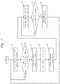
Fig. 3 is a flowchart illustrating operations of thecooling system 10 according to Embodiment 1. -
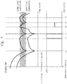
Fig. 4 is a diagram illustrating a relationship among a rotation speed of a motor of ablower 122, a frequency of acompressor 111, and a Coefficient Of Performance (COP) of thecooling system 10. -
Fig. 5 is a diagram illustrating a specific example of the operations of thecooling system 10 according to Embodiment 1. -
Fig. 6 is a configuration diagram of acooling system 10 according to Embodiment 2. -
Fig. 7 is a configuration diagram of acooling control device 13 according to Embodiment 2. -
Fig. 8 is a flowchart illustrating operations of thecooling system 10 according to Embodiment 2. -
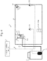
Fig. 9 is a configuration diagram of acooling system 10 according to Embodiment 3. - A configuration of a
cooling system 10 according to Embodiment 1 will be described with referring toFig. 1 . - The
cooling system 10 is a system that constitutes a vapor compression type refrigeration cycle to cool atarget space 50. - The
cooling system 10 is provided with aheat source machine 11, acooling machine 12, acooling control device 13, and a plurality oftemperature sensors 14 installed at different positions in thetarget space 50. Theheat source machine 11 and thecooling machine 12 are connected to each other via arefrigerant pipe 15 so as to constitute the vapor compression type refrigeration cycle. Thecooling control device 13 is connected to theheat source machine 11, thecooling machine 12, and thetemperature sensors 14, via asignal line 16. - The
heat source machine 11 is installed outside of thetarget space 50. Theheat source machine 11 is provided with an apparatus such as aninverter type compressor 111. Thecooling machine 12 is installed in thetarget space 50 by ahanging tool 17 or the like. Thecooling machine 12 is provided with apparatuses such as aheat exchanger 121 and aninverter type blower 122. Theheat exchanger 121 exchanges heat between a refrigerant cooled by theheat source machine 11 and air in thetarget space 50, thereby cooling the air in thetarget space 50. - In
Fig. 1 , thecooling system 10 is provided with twotemperature sensors 14 which are atemperature sensor 14A and atemperature sensor 14B, as the plurality oftemperature sensors 14. InFig. 1 , thetemperature sensor 14A is installed in the vicinity of thecooling machine 12, and thetemperature sensor 14B is installed deep in thetarget space 50 and remote from thecooling machine 12. - A configuration of the
cooling control device 13 according to Embodiment 1 will be described with referring toFig. 2 . - The
cooling control device 13 is a computer such as a microcomputer. - The
cooling control device 13 is provided with atemperature acquisition unit 21, atemperature checking unit 22, awind control unit 23, and afrequency control unit 24, as function constituent elements. - The
temperature acquisition unit 21 acquires temperatures detected by the plurality oftemperature sensors 14. Thewind control unit 23 refers to the temperatures acquired by thetemperature acquisition unit 21 so as to identify a target position where atemperature sensor 14 that has detected a temperature higher than a reference temperature is installed, among the plurality oftemperature sensors 14. Thewind control unit 23 controls an air volume of theblower 122 so that an upper limit of reach of air cooled by theheat exchanger 121 is within a target range defined about the target position as a reference. Thefrequency control unit 24 controls thecompressor 111 with a frequency that increases an operation efficiency in accordance with the air volume controlled by thewind control unit 23. - Operations of the
cooling system 10 according to Embodiment 1 will be described with referring toFigs. 3 to 5 . - The operations of the
cooling system 10 according to Embodiment 1 correspond to a cooling control method according to Embodiment 1. - As a premise of following operations, an upper limit temperature and a lower limit temperature, and installation positions of the
temperature sensors 14 are set in thecooling control device 13. Atemperature sensor 14 located at a position where the temperature tends to rise most easily is also set in thecooling control device 13. The position where the temperature tends to rise most easily is a position that is the most remote from theblower 122 and that is the highest position. - Specifically, the upper limit temperature and the lower limit temperature, the installation positions of the
temperature sensors 14, and an identifier of thetemperature sensor 14 located at the position where the temperature tends to rise most easily are entered by a user and are stored in a memory of thecooling control device 13. - The
temperature sensors 14 detect temperatures. Thetemperature acquisition unit 21 of thecooling control device 13 acquires, via thesignal line 16, the temperatures detected by thetemperature sensors 14. - The
temperature checking unit 22 of thecooling control device 13 checks whether or not a temperature higher than the upper limit temperature, which is the reference temperature, is included in the temperatures acquired by thetemperature acquisition unit 21 in step S11. Note that in Embodiment 1, the upper limit temperature is used as the reference temperature. However, the reference temperature may be set independently of the upper limit temperature. - If a temperature higher than the upper limit temperature is included, the
temperature checking unit 22 forwards processing to step S13. On the other hand, if a temperature higher than the upper limit temperature is not included, thetemperature checking unit 22 returns the processing back to step S11. - The
wind control unit 23 of thecooling control device 13 identifies atemperature sensor 14 that has detected a temperature higher than the upper limit temperature, as atarget temperature sensor 14. - There is a case where a plurality of
temperature sensors 14 detect temperatures higher than the upper limit temperature. According to Embodiment 1, in this case, thewind control unit 23 identifies atemperature sensor 14 located at a position where the temperature tends to rise most easily, as thetarget temperature sensor 14. InFig. 1 , if both thetemperature sensor 14A and thetemperature sensor 14B detect temperatures higher than the upper limit temperature, thewind control unit 23 identifies thetemperature sensor 14B located at the position remote from theblower 122, as thetarget temperature sensor 14. - The
wind control unit 23 of thecooling control device 13 identifies the position where thetarget temperature sensor 14 identified in step S13 is installed, as the target position. Then, thewind control unit 23 controls the air volume of theblower 122 so that the upper limit of reach of air cooled by the heat exchanger is within the target range defined about the target position as the reference. That is, thewind control unit 23 controls theblower 122 to have such an air volume that air cooled by theheat exchanger 121 does not reach farther than the target range defined about the target position as the reference. As theblower 122 is of the inverter type, theblower 122 can control the air volume by changing a motor rotation speed by frequency control. Theblower 122 changes the motor rotation speed according to control of thewind control unit 23. - The target range is a predetermined range including the target position and around the target position. For this reason, in the configuration of
Fig. 1 , if thetemperature sensor 14 that has detected the temperature higher than the upper limit temperature is thetemperature sensor 14B, the air volume of theblower 122 is controlled so that the cooled air reaches the vicinity of the position where thetemperature sensor 14B is installed. In contrast to this, if thetemperature sensor 14 that has detected the temperature higher than the upper limit temperature is thetemperature sensor 14A, the air volume of theblower 122 is reduced so that the cooled air does not reach farther than the vicinity of the position where thetemperature sensor 14A is installed. - When the plurality of
temperature sensors 14 have detected temperatures higher than the upper limit temperature, thewind control unit 23 takes as the target position a position of thetemperature sensor 14 that is the most remote from theblower 122 and that is installed at the highest position. Then, thewind control unit 23 controls the air volume of theblower 122 so that the upper limit of reach of air cooled by a heat exchanger is within the target range defined about the target position as the reference. When the air volume is controlled so that the cooled air reaches a position that is the most remote from theblower 122 and that is the highest position, the cooled air reaches also the other positions in thetarget space 50. This consequently cools also positions where thetemperature sensors 14 that have detected temperatures higher than the upper limit temperature are installed. - The
frequency control unit 24 of thecooling control device 13 controls thecompressor 111 with a frequency that increases an operation efficiency in accordance with the air volume controlled in step S14. As thecompressor 111 is of the inverter type, thecompressor 111 can change the rotation speed by frequency control, thereby changing the operation capacity. Thecompressor 111 changes the rotation speed according to control of thefrequency control unit 24. - As illustrated in
Fig. 4 , a frequency of thecompressor 111 that increases a Coefficient Of Performance (COP) of thecooling system 10 differs depending on the motor rotation speed of theblower 122.Fig. 4 illustrates the COP of thecooling system 10 for rotation speeds of theblower 122 which are obtained by changing the frequency of thecompressor 111 while using, as a reference, a case where the frequency of thecompressor 111 is 100%. - In the case of
Fig. 4 , if the rotation speed of the motor of theblower 122 is 100%, when the frequency of thecompressor 111 is lowered, the COP of thecooling system 10 becomes lower than in the case where the frequency of thecompressor 111 is 100%. In contrast to this, if the rotation speed of the motor of theblower 122 is 40% or 60%, when the frequency of thecompressor 111 is lowered, the COP of thecooling system 10 becomes higher than in the case where the frequency of thecompressor 111 is 100%. Hence, if the rotation speed of the motor of theblower 122 is controlled at 100%, thefrequency control unit 24 controls the frequency of thecompressor 111 at 100%. Meanwhile, if the rotation speed of the motor of theblower 122 is controlled at 40% or 60%, thefrequency control unit 24 controls the frequency of thecompressor 111 to a frequency that is lower than 100% and at which the COP of thecooling system 10 becomes the highest. - In
Fig. 4 , each curve of the graph is interrupted. This is because if the frequency of thecompressor 111 is set excessively low, a refrigerating capacity necessary for processing a load cannot be obtained.Fig. 4 expresses that if the motor rotation speed of theblower 122 is 100%, when the frequency of thecompressor 111 is set lower than 25%, a necessary refrigerating capacity cannot be obtained. Likewise,Fig. 4 expresses that if the motor rotation speed of theblower 122 is 60%, when the frequency of thecompressor 111 is set lower than 50%, a necessary refrigerating capacity cannot be obtained; and that if the motor rotation speed of theblower 122 is 40%, when the frequency of thecompressor 111 is set lower than 75%, a necessary refrigerating capacity cannot be obtained. - The
target temperature sensor 14 identified in step S13 detects temperature. Thetemperature acquisition unit 21 of thecooling control device 13 acquires the temperature detected by thetarget temperature sensor 14, via thesignal line 16. - The
temperature checking unit 22 of thecooling control device 13 checks whether or not the temperature detected by thetarget temperature sensor 14, which is acquired in step S16 by thetemperature acquisition unit 21, is lower than the lower limit temperature. - If the temperature is lower than the lower limit temperature, the
temperature checking unit 22 forwards the processing to step S18. On the other hand, if the temperature is equal to or higher than the lower limit temperature, thetemperature checking unit 22 returns the processing back to step S16. - The
wind control unit 23 of thecooling control device 13 performs control to stop the motor of theblower 122. Theblower 122 stops the motor in accordance with control by thewind control unit 23. Also, thefrequency control unit 24 of thecooling control device 13 performs control to stop thecompressor 111. Thecompressor 111 stops in accordance with control by thefrequency control unit 24. - A specific example of the operations of the
cooling system 10 according to Embodiment 1 will be described with referring toFig. 5 . - In
Fig. 5 , thecooling system 10 has the configuration illustrated inFig. 1 , and the COP of thecooling system 10 holds a relationship illustrated inFig. 4 . - At time point t0, the
cooling system 10 starts operation. At this time, a temperature TA detected by thetemperature sensor 14A and a temperature TB detected by thetemperature sensor 14B are both higher than the upper limit temperature. As the temperatures higher than the upper limit temperature are detected, the processing advances from step S12 to step S13 ofFig. 3 . - In step S13 of
Fig. 3 , as the plurality oftemperature sensors 14 have detected temperatures higher than the upper limit temperature, thetemperature sensor 14B, which is located at a position where the temperature tends to rise most easily, is identified as thetarget temperature sensor 14. In step S14 ofFig. 3 , theblower 122 is controlled with a motor rotation speed of 100% so that cooled air reaches a periphery of the position where thetemperature sensor 14B is installed. Accordingly, in step S15 ofFig. 3 , the frequency of thecompressor 111 is controlled at 100% so that the CPO of thecooling system 10 becomes high. - Then, the temperature TA and the temperature TB fall gradually.
- At time point t1, the temperature TB detected by the
temperature sensor 14B, being thetarget temperature sensor 14, has dropped below the lower limit temperature. As the temperature TB is lower than the lower limit temperature, the processing advances from step S17 to step S18 ofFig. 3 . Then, in step S18 ofFig. 3 , the motor of theblower 122 is stopped, and thecompressor 111 is stopped. - Then, the temperature TA and the temperature TB rise gradually.
- At time point t2, the temperature TB has risen above the upper limit temperature. As a temperature higher than the upper limit temperature is detected, the processing advances from step S12 to step S13 of
Fig. 3 . - In step S13 of
Fig. 3 , thetemperature sensor 14B that has detected the temperature higher than the upper limit temperature is identified as thetarget temperature sensor 14. Then, in step S14 of Fig. 13, theblower 122 is controlled with a motor rotation speed of 100% so that the cooled air reaches the periphery of the position where thetemperature sensor 14B is installed. Accordingly, in step S15 ofFig. 3 , the frequency of thecompressor 111 is controlled at 100% so that the COP of thecooling system 10 becomes high. - Then, the temperature TA and the temperature TB fall gradually.
- At time point t3, the temperature TB detected by the
temperature sensor 14B, being thetarget temperature sensor 14, has dropped below the lower limit temperature. As the temperature TB is lower than the lower limit value, the processing advances from step S17 to step S18 ofFig. 3 . In step S18 ofFig. 3 , the motor of theblower 122 is stopped, and thecompressor 111 is stopped. - Then, the temperature TA and the temperature TB rise gradually.
- At time point t4, the temperature TA has risen above the upper limit temperature. At this time, the temperature TB is equal to or lower than the upper limit temperature. It is possible that, due to some influence such as loading of an stock item to a warehouse, the temperature will become higher at a position where the temperature does not rise easily and where the
temperature sensor 14A is installed, than at a position where the temperature tends to rise easily and where thetemperature sensor 14B is installed. As a temperature higher than the upper limit temperature is detected, the processing advances from step S12 to step S13 ofFig. 3 . - In step S13 of
Fig. 3 , thetemperature sensor 14A that has detected the temperature higher than the upper limit temperature is identified as thetarget temperature sensor 14. Then, in step S14 ofFig. 3 , theblower 122 is controlled so that the cooled air does not reach farther than the periphery of the position where thetemperature sensor 14A is installed. Assume that theblower 122 is controlled with a motor rotation speed of 40%. Accordingly, in step S15 ofFig. 3 , the frequency of thecompressor 111 is controlled at 75% so that the COP of thecooling system 10 becomes high. - Then, the temperature TA and the temperature TB fall gradually.
- Particularly, the temperature TA detected by the
temperature sensor 14A falls sharply, thetemperature sensor 14A being installed at the position to which the cooled air is sent, as compared to the temperature TB detected by thetemperature sensor 14B installed at the position which the cooled air does not reach directly. - At time point t5, the temperature TA detected by the
temperature sensor 14A, being thetarget temperature sensor 14, has dropped below the lower limit temperature. As the temperature TA is lower than the lower limit temperature, the processing advances from step S17 to step S18 ofFig. 3 . Then, in step S18 ofFig. 3 , the motor of theblower 122 is stopped, and thecompressor 111 is stopped. - Then, the temperature TA and the temperature TB rise gradually.
- At time point t6, the temperature TB has risen above the upper limit temperature. As a temperature higher than the upper limit temperature is detected, the processing advances from step S12 to step S13 of
Fig. 3 . - In step S13 of
Fig. 3 , thetemperature sensor 14B that has detected the temperature higher than the upper limit temperature is identified as thetemperature sensor 14. Then, in step S14 ofFig. 3 , theblower 122 is controlled with a motor rotation speed of 100% so that the cooled air reaches the periphery of the position where thetemperature sensor 14B is installed. Accordingly, in step S15 ofFig. 3 , the frequency of thecompressor 111 is controlled at 100% so that the COP of thecooling system 10 becomes high. - Then, the temperature TA and the temperature TB fall gradually.
- As described above, in the
cooling system 10 according to Embodiment 1, the air volume of theblower 122 is controlled so that the upper limit of reach of air cooled by theheat exchanger 121 is within the target range defined about, as a reference, the target position where thetemperature sensor 14 that has detected a temperature higher than the upper limit temperature is installed. This makes it possible to send the cooled air to the temperature-risen position while reducing the power consumption. As a result, it has become possible to perform control to reduce power consumption while decreasing temperature non-uniformities in the target space. - Also, in the
cooling system 10 according to Embodiment 1, thecompressor 111 is controlled with a frequency that increases an operation efficiency in accordance with the air volume of theblower 122. This makes it possible to perform control so as to further decrease the power consumption. - The
wind control unit 23 may control the air volume considering a temperature-increase trend. - According to a specific example, assume that even if a temperature detected by one
temperature sensor 14 is equal to or lower than the upper limit temperature, an increase per unit time of the temperature detected by thattemperature sensor 14 is equal to or larger than a threshold value. In this case, thewind control unit 23 may control the air volume of theblower 122 so that the upper limit of reach of air cooled by theheat exchanger 121 is within a target range defined about, as a reference, the target position where thetemperature sensor 14 is installed. - For example, assume that the
temperature sensor 14A and thetemperature sensor 14B are arranged as illustrated inFig. 1 . Assume that, at this time, a temperature detected by thetemperature sensor 14A is equal to or lower than the upper limit temperature, but an increase per unit time of the temperature detected by thetemperature sensor 14A is equal to or larger than the threshold value. In this case, thewind control unit 23 may control an air volume of theblower 122 so that the upper limit of reach of air cooled by theheat exchanger 121 is within a target range defined about, as a reference, the target position where thetemperature sensor 14A is installed. - The
wind control unit 23 may identify thetarget temperature sensor 14 considering the temperature-increase trend. - According to a specific example, assume that the plurality of
temperature sensors 14 having detected temperatures higher than the upper limit temperature include atemperature sensor 14 indicating an increase in detected temperature per unit time that is equal to or larger than the threshold value. In this case, atemperature sensor 14 indicting a temperature increase per unit time that is equal to or larger than the threshold value may be identified as thetarget temperature sensor 14, in place of atemperature sensor 14 located at a position where the temperature tends to rise most easily. - For example, assume that the
temperature sensor 14A and thetemperature sensor 14B are arranged as illustrated inFig. 1 . Assume that, at this time, a temperature detected by thetemperature sensor 14A and a temperature detected by thetemperature sensor 14B are both equal to or higher than the upper limit value. In this case, according to Embodiment 1, thewind control unit 23 identifies thetemperature sensor 14B located at a position deep in thetarget space 50 and remote from the coolingmachine 12, as thetarget temperature sensor 14. Alternatively, if an increase per unit time of the temperature detected by thetemperature sensor 14A is equal to or larger than the threshold value, thewind control unit 23 may identify thetemperature sensor 14A as thetarget temperature sensor 14. - In Embodiment 1, the
cooling system 10 is provided with the twotemperature sensors 14, as illustrated inFig. 1 . Alternatively, thecooling system 10 may be provided with three ormore temperature sensors 14. At this time, at least onetemperature sensor 14 is desirably arranged deep in thetarget space 50 and remote from the coolingmachine 12. Besides,temperature sensors 14 are desirably arranged at positions such as near an outlet/inlet of thetarget space 50 and near a position where the stock item is placed. - An upper limit temperature and a lower limit temperature are set higher for a
temperature sensor 14 installed in an area other than a periphery of a position where a stock item is placed, rather than for atemperature sensor 14 installed on the periphery. In this respect, Embodiment 2 is different from Embodiment 1. In Embodiment 2, this difference will be described, and the same feature will not be described. - A configuration of a
cooling system 10 according to Embodiment 2 will be described with referring toFig. 6 . - The
cooling system 10 is provided with adetection sensor 18. In this respect, thecooling system 10 is different from thecooling system 10 according to Embodiment 1. Thedetection sensor 18 is a sensor that detects a position where a stock item is placed in atarget space 50. - A configuration of the
cooling control device 13 according to Embodiment 2 will be described with referring toFig. 7 . - The cooling
control device 13 is provided with a stockitem identification unit 25 and a settingchange unit 26. In this respect, the coolingcontrol device 13 is different from the coolingcontrol device 13 according to Embodiment 1. By thedetection sensor 18, the stockitem identification unit 25 identifies the position where the stock item is placed in thetarget space 50. The settingchange unit 26 sets the upper limit temperature and the lower limit temperature higher for thetemperature sensor 14 installed in an area other than a peripheral area on the periphery of the position where the stock item identified by the stockitem identification unit 25 is placed, rather than for thetemperature sensor 14 installed in the peripheral area . - Operations of the
cooling system 10 according to Embodiment 2 will be described with referring toFig. 8 . - The operations of the
cooling system 10 according to Embodiment 2 correspond to a cooling control method according to Embodiment 2. - Processes of step S23 to step S30 are the same as the processes of step S11 to step S18 of
Fig. 3 . - The stock
item identification unit 25 acquires a detection result of thedetection sensor 18 and identifies the position where the stock item is placed in thetarget space 50, on the basis of the detection result. - The setting
change unit 26 identifies thetemperature sensor 14 installed in the peripheral area which is on the periphery of the position where the stock item identified in step S21 is placed. Specifically, the settingchange unit 26 takes, as the peripheral area, a range within a reference distance about the position where the stock item identified in step S21 is placed, and identifies atemperature sensor 14 whose installation position is included in the peripheral area. - Then, the setting
change unit 26 sets an upper limit temperature and a lower limit temperature that are each higher by a correction temperature, for thetemperature sensor 14 other than the identifiedtemperature sensor 14. The correction temperature is a temperature that is set in advance by a user. - As described above, in the
cooling system 10 according to Embodiment 2, the upper limit temperature and the lower limit temperature are set higher for thetemperature sensor 14 installed in the area other than the periphery of the position where the stock item is placed, rather than for thetemperature sensor 14 installed on the periphery. Hence, a temperature detected by thetemperature sensor 14 installed at a position where no stock item is placed does not exceed the upper limit temperature easily. As a result, less often, an air volume of theblower 122 is increased to reach the area where no stock item is placed. This makes it possible to reduce power consumption. - In Embodiment 2, processes of step S21 and step S22 in
Fig. 8 are executed only at the start of operation of thecooling system 10, and the upper limit temperature and the lower limit temperature are set. Alternatively, the processes of step S21 and step S22 ofFig. 8 may be executed periodically, or at an occurrence of an event such as unloading/loading of a stock item. - Embodiment 3 is different from Embodiment 1 or 2 in that a wind direction is controlled. In Embodiment 3, this difference will be described, and the same feature will not be described.
- In Embodiment 3, an example obtained by adding a function to Embodiment 1 will be described. Alternatively, it is possible to add a function to Embodiment 2.
- A configuration of a
cooling system 10 according to Embodiment 3 will be described with referring toFig. 9 . - In
Fig. 9 , only configurations of part of thecooling system 10 are illustrated, and configurations such as aheat source machine 11 and acooling control device 13 are omitted. - The
cooling system 10 is provided with a plurality oftemperature sensors 14 also in a right and left direction (Y-direction ofFig 9 ) which is perpendicular to a blowing direction (X-direction ofFig. 9 ) of ablower 122. In this respect, thecooling system 10 is different from thecooling system 10 according to Embodiment 1. Note that inFig. 9 , thecooling system 10 is provided with a plurality oftemperature sensors 14 also in a vertical direction (Z-direction ofFig. 9 ). - In the
cooling system 10, a coolingmachine 12 is provided with aflap 123. In this respect, thecooling system 10 is different from thecooling system 10 according to Embodiment 1. Theflap 123 is disposed in the vicinity of a blowing port of theblower 122. Theflap 123 is a device that changes an orientation in the right and left direction (Y-direction ofFig. 9 ) of wind being blown by theblower 122. - Operations of the
cooling system 10 according to Embodiment 3 will be described with referring toFig. 3 . - The operations of the
cooling system 10 according to Embodiment 3 correspond to a cooling control method according to Embodiment 3. - Processes of step S11 to step S13 and processes of step S15 to step S18 are the same as their counterparts in Embodiment 1.
- A
wind control unit 23 of thecooling control device 13 controls an air volume of theblower 122 so that an upper limit of reach of air cooled by aheat exchanger 121 is within a target range defined about a target position as a reference, just as in Embodiment 1. In this case, by controlling theflap 123, thewind control unit 23 controls wind direction so that wind is sent to the target position. - As described above, in the
cooling system 10 according to Embodiment 3, not only the air volume but also the wind direction of theblower 122 is controlled. This makes it possible to send cooled air to a temperature-risen position with accuracy. As a result, it has become possible to perform control to reduce power consumption while reducing temperature non-uniformities in the target space. - As illustrated in
Fig. 9 , by arranging the plurality oftemperature sensors 14 in the blowing direction (X-direction inFig. 9 ), the right and left direction (Y-direction inFig. 9 ), and the vertical direction (Z-direction inFig. 9 ), the temperature of thetarget space 50 can be grasped accurately per position. As a result, the air volume and wind direction can be controlled appropriately. - Embodiments and modifications of the present invention have been described above. Of these embodiments and modifications, several ones may be practiced by combination. Also, one or several ones of these embodiments and modifications may be practiced partially. Note that the present invention is not limited to the above-mentioned embodiments and modifications, but can be changed in various manners as necessary.
- 10: cooling system; 11: heat source machine; 12: cooling machine; 13: cooling control device; 14: temperature sensor; 15: refrigerant pipe; 16: signal line; 17: hanging tool; 18: detection sensor; 111: compressor; 121: heat exchanger; 122: blower; 123: flap; 21: temperature acquisition unit; 22: temperature checking unit; 23: wind control unit; 24: frequency control unit; 25: stock item identification unit; 26: setting change unit; 50: target space.
Claims (7)
- A cooling control device comprising:a temperature acquisition unit to acquire temperatures detected by a plurality of temperature sensors installed at different positions in a target space; anda wind control unit to refer to the temperatures acquired by the temperature acquisition unit so as to identify a target position, and to control an air volume of a blower so that an upper limit of reach of air cooled by a heat exchanger is within a target range defined about, as a reference, the target position where a temperature sensor that has detected a temperature higher than a reference temperature is installed, among the plurality of temperature sensors.
- The cooling control device according to claim 1,wherein the heat exchanger is a device that exchanges heat between a refrigerant and air in the target space, in a vapor compression type cooling cycle having a compressor,the cooling control device further comprisinga frequency control unit to control the compressor with a frequency that increases an operation efficiency in accordance with the air volume controlled by the wind control unit.
- The cooling control device according to claim 1 or 2,
wherein the wind control unit identifies, as the target position, a position where a temperature sensor indicating a temperature increase per unit time that is equal to or larger than a threshold value is installed. - The cooling control device according to any one of claims 1 to 3, further comprising:a stock item identification unit to identify a position where a stock item is placed in the target space; anda setting change unit to set a reference temperature higher for a temperature sensor installed in an area other than a peripheral area which is on a periphery of a position where the stock item identified by the stock item identification unit is installed, rather than for a temperature sensor installed in the peripheral area.
- The cooling control device according to any one of claims 1 to 4,
wherein the wind control unit controls a wind direction so that wind is sent to the target position. - A cooling system comprising:a heat exchanger to cool air in a target space;a blower to send air cooled by the heat exchanger;a plurality of temperature sensors installed at different positions in the target space; anda cooling control device to control an air volume of the blower so that an upper limit of reach of air cooled by the heat exchanger is within a target range defined about, as a reference, a target position where a temperature sensor that has detected a temperature higher than a reference temperature is installed, among the plurality of temperature sensors.
- A cooling control method comprising:by a plurality of temperature sensors installed at different positions in a target space, detecting temperatures of positions where the plurality of temperature sensors are installed; andby a cooling control device, controlling an air volume of a blower so that an upper limit of reach of air cooled by a heat exchanger is within a target range defined about, as a reference, a target position where a temperature sensor that has detected a temperature higher than a reference temperature is installed, among the plurality of temperature sensors.
Applications Claiming Priority (1)
| Application Number | Priority Date | Filing Date | Title |
|---|---|---|---|
| PCT/JP2019/019855 WO2020234952A1 (en) | 2019-05-20 | 2019-05-20 | Cooling control device, cooling system, and cooling control method |
Publications (2)
| Publication Number | Publication Date |
|---|---|
| EP3974748A1 true EP3974748A1 (en) | 2022-03-30 |
| EP3974748A4 EP3974748A4 (en) | 2022-05-18 |
Family
ID=73458175
Family Applications (1)
| Application Number | Title | Priority Date | Filing Date |
|---|---|---|---|
| EP19929282.2A Withdrawn EP3974748A4 (en) | 2019-05-20 | 2019-05-20 | COOLING CONTROL DEVICE, COOLING SYSTEM AND COOLING CONTROL METHOD |
Country Status (4)
| Country | Link |
|---|---|
| US (1) | US20220186968A1 (en) |
| EP (1) | EP3974748A4 (en) |
| JP (1) | JP7150160B2 (en) |
| WO (1) | WO2020234952A1 (en) |
Families Citing this family (2)
| Publication number | Priority date | Publication date | Assignee | Title |
|---|---|---|---|---|
| CN113654199B (en) * | 2021-08-06 | 2022-09-27 | 美的集团武汉制冷设备有限公司 | Air conditioner control method, air conditioner and medium |
| WO2025010305A1 (en) * | 2023-07-03 | 2025-01-09 | Doubleday Acquisitions Llc | Thermally controlled container |
Family Cites Families (15)
| Publication number | Priority date | Publication date | Assignee | Title |
|---|---|---|---|---|
| JP2000130913A (en) * | 1998-10-28 | 2000-05-12 | Toshiba Corp | refrigerator |
| US6862179B2 (en) * | 2002-11-26 | 2005-03-01 | Hewlett-Packard Development Company, L.P. | Partition for varying the supply of cooling fluid |
| KR101570376B1 (en) * | 2009-02-10 | 2015-11-20 | 엘지전자 주식회사 | Refrigerator |
| EP2454533B1 (en) * | 2009-07-13 | 2019-11-13 | Carrier Corporation | Transport refrigeration system, transport refrigeration unit, and methods for same |
| WO2011050157A2 (en) * | 2009-10-23 | 2011-04-28 | Carrier Corporation | Spatial control of conditioned gas delivery for transport refrigeration system to include cargo spatial temperature distribution, and methods for same |
| WO2012047938A2 (en) * | 2010-10-04 | 2012-04-12 | Global Solar Water And Power Systems, Inc. | Multiplatform heating ventilation and air conditioning control system |
| RU2622352C2 (en) * | 2011-12-12 | 2017-06-14 | Индезит Компани С.П.А. | Method and device for managing the cooling device and cooling unit that realizes the mentioned method |
| PL2859286T3 (en) * | 2012-06-06 | 2016-10-31 | A cooling device with two compartments | |
| JP6313935B2 (en) * | 2013-06-27 | 2018-04-18 | 株式会社MARS Company | Refrigerator |
| JP6334146B2 (en) | 2013-11-27 | 2018-05-30 | 東芝ライフスタイル株式会社 | refrigerator |
| CN104879977A (en) * | 2014-02-28 | 2015-09-02 | 株式会社电装 | Tempering storage device |
| US20150316309A1 (en) * | 2014-05-02 | 2015-11-05 | Thermo King Corporation | Transport refrigeration system with air temperature control |
| JP6215485B2 (en) * | 2014-10-30 | 2017-10-18 | 株式会社MARS Company | Refrigerator |
| JP6511991B2 (en) * | 2015-06-30 | 2019-05-15 | 富士電機株式会社 | Cold storage |
| US20180178626A1 (en) * | 2016-12-23 | 2018-06-28 | Thermo King Corporation | Systems and methods of dynamic airflow control within an internal space |
-
2019
- 2019-05-20 JP JP2021520516A patent/JP7150160B2/en active Active
- 2019-05-20 EP EP19929282.2A patent/EP3974748A4/en not_active Withdrawn
- 2019-05-20 WO PCT/JP2019/019855 patent/WO2020234952A1/en not_active Ceased
- 2019-05-20 US US17/439,643 patent/US20220186968A1/en not_active Abandoned
Also Published As
| Publication number | Publication date |
|---|---|
| JPWO2020234952A1 (en) | 2021-10-14 |
| WO2020234952A1 (en) | 2020-11-26 |
| EP3974748A4 (en) | 2022-05-18 |
| JP7150160B2 (en) | 2022-10-07 |
| US20220186968A1 (en) | 2022-06-16 |
Similar Documents
| Publication | Publication Date | Title |
|---|---|---|
| US8285420B2 (en) | Control device, control method, and control program | |
| US9810469B2 (en) | Variable fan speed control in HVAC systems and methods | |
| CN104634063B (en) | The control method of refrigerator, the control device of refrigerator and refrigerator | |
| EP3974748A1 (en) | Cooling control device, cooling system, and cooling control method | |
| EP2525639A2 (en) | Cooling system for electronic equipment | |
| CN102032139B (en) | System and method for adjusting energy of magnetic suspension compressor | |
| CN115614910B (en) | Refrigerant bias flow processing method and device and modularized air conditioning unit | |
| JP2012193892A (en) | Cooling device | |
| US20190170433A1 (en) | Control device, program, control method of refrigerator, and refrigerator | |
| US5850969A (en) | Method for controlling temperature in a refrigerator when a temperature sensor operates abnormally | |
| CN109827301B (en) | Speed regulation method of air conditioner fan, storage medium and air conditioning system | |
| CN109714937B (en) | Control method of heat dissipation system of electrical cabinet | |
| US11299011B2 (en) | Vehicular air-conditioning apparatus and air-conditioning method of vehicular air-conditioning apparatus | |
| WO2020070833A1 (en) | Outdoor unit, indoor unit, and air conditioner | |
| JP2010211363A (en) | Electronic equipment cooling device | |
| EP3943827A1 (en) | Data center air conditioning control device, method, non-transitory computer readable medium, and air conditioning system | |
| US11543163B2 (en) | Method and system for charge determination | |
| JP6509457B2 (en) | Control system and control device | |
| KR102908311B1 (en) | Air conditioning system, electronic device, and cotnrol method of the same | |
| CN116608557A (en) | Mounting position judging method and device, air conditioner and computer readable storage medium | |
| CN117387303A (en) | Refrigerator control method, device, refrigerator and storage medium | |
| JP2016070560A (en) | Air conditioner | |
| CN111473600B (en) | Refrigerator and control method thereof | |
| JP6384042B2 (en) | Refrigeration system | |
| JP2021148333A (en) | Air conditioning system |
Legal Events
| Date | Code | Title | Description |
|---|---|---|---|
| STAA | Information on the status of an ep patent application or granted ep patent |
Free format text: STATUS: THE INTERNATIONAL PUBLICATION HAS BEEN MADE |
|
| PUAI | Public reference made under article 153(3) epc to a published international application that has entered the european phase |
Free format text: ORIGINAL CODE: 0009012 |
|
| STAA | Information on the status of an ep patent application or granted ep patent |
Free format text: STATUS: REQUEST FOR EXAMINATION WAS MADE |
|
| 17P | Request for examination filed |
Effective date: 20211110 |
|
| AK | Designated contracting states |
Kind code of ref document: A1 Designated state(s): AL AT BE BG CH CY CZ DE DK EE ES FI FR GB GR HR HU IE IS IT LI LT LU LV MC MK MT NL NO PL PT RO RS SE SI SK SM TR |
|
| A4 | Supplementary search report drawn up and despatched |
Effective date: 20220420 |
|
| RIC1 | Information provided on ipc code assigned before grant |
Ipc: F25B 49/02 20060101ALI20220412BHEP Ipc: F24F 110/10 20180101ALI20220412BHEP Ipc: F25D 17/06 20060101ALI20220412BHEP Ipc: F24F 11/86 20180101ALI20220412BHEP Ipc: F24F 11/79 20180101ALI20220412BHEP Ipc: F24F 11/74 20180101ALI20220412BHEP Ipc: F25D 13/00 20060101AFI20220412BHEP |
|
| DAV | Request for validation of the european patent (deleted) | ||
| DAX | Request for extension of the european patent (deleted) | ||
| STAA | Information on the status of an ep patent application or granted ep patent |
Free format text: STATUS: EXAMINATION IS IN PROGRESS |
|
| 17Q | First examination report despatched |
Effective date: 20231127 |
|
| GRAP | Despatch of communication of intention to grant a patent |
Free format text: ORIGINAL CODE: EPIDOSNIGR1 |
|
| STAA | Information on the status of an ep patent application or granted ep patent |
Free format text: STATUS: GRANT OF PATENT IS INTENDED |
|
| INTG | Intention to grant announced |
Effective date: 20250314 |
|
| STAA | Information on the status of an ep patent application or granted ep patent |
Free format text: STATUS: THE APPLICATION IS DEEMED TO BE WITHDRAWN |
|
| 18D | Application deemed to be withdrawn |
Effective date: 20250715 |