EP3974695A1 - Duct connection and fastening means for a duct connection - Google Patents
Duct connection and fastening means for a duct connection Download PDFInfo
- Publication number
- EP3974695A1 EP3974695A1 EP20290065.0A EP20290065A EP3974695A1 EP 3974695 A1 EP3974695 A1 EP 3974695A1 EP 20290065 A EP20290065 A EP 20290065A EP 3974695 A1 EP3974695 A1 EP 3974695A1
- Authority
- EP
- European Patent Office
- Prior art keywords
- duct
- bracket
- interface segment
- connection
- ducts
- Prior art date
- Legal status (The legal status is an assumption and is not a legal conclusion. Google has not performed a legal analysis and makes no representation as to the accuracy of the status listed.)
- Granted
Links
Images


Classifications
-
- F—MECHANICAL ENGINEERING; LIGHTING; HEATING; WEAPONS; BLASTING
- F16—ENGINEERING ELEMENTS AND UNITS; GENERAL MEASURES FOR PRODUCING AND MAINTAINING EFFECTIVE FUNCTIONING OF MACHINES OR INSTALLATIONS; THERMAL INSULATION IN GENERAL
- F16L—PIPES; JOINTS OR FITTINGS FOR PIPES; SUPPORTS FOR PIPES, CABLES OR PROTECTIVE TUBING; MEANS FOR THERMAL INSULATION IN GENERAL
- F16L47/00—Connecting arrangements or other fittings specially adapted to be made of plastics or to be used with pipes made of plastics
- F16L47/18—Adjustable joints; Joints allowing movement
-
- F—MECHANICAL ENGINEERING; LIGHTING; HEATING; WEAPONS; BLASTING
- F02—COMBUSTION ENGINES; HOT-GAS OR COMBUSTION-PRODUCT ENGINE PLANTS
- F02M—SUPPLYING COMBUSTION ENGINES IN GENERAL WITH COMBUSTIBLE MIXTURES OR CONSTITUENTS THEREOF
- F02M35/00—Combustion-air cleaners, air intakes, intake silencers, or induction systems specially adapted for, or arranged on, internal-combustion engines
- F02M35/10—Air intakes; Induction systems
- F02M35/10091—Air intakes; Induction systems characterised by details of intake ducts: shapes; connections; arrangements
- F02M35/10144—Connections of intake ducts to each other or to another device
-
- F—MECHANICAL ENGINEERING; LIGHTING; HEATING; WEAPONS; BLASTING
- F02—COMBUSTION ENGINES; HOT-GAS OR COMBUSTION-PRODUCT ENGINE PLANTS
- F02M—SUPPLYING COMBUSTION ENGINES IN GENERAL WITH COMBUSTIBLE MIXTURES OR CONSTITUENTS THEREOF
- F02M35/00—Combustion-air cleaners, air intakes, intake silencers, or induction systems specially adapted for, or arranged on, internal-combustion engines
- F02M35/10—Air intakes; Induction systems
- F02M35/10314—Materials for intake systems
- F02M35/10321—Plastics; Composites; Rubbers
-
- F—MECHANICAL ENGINEERING; LIGHTING; HEATING; WEAPONS; BLASTING
- F16—ENGINEERING ELEMENTS AND UNITS; GENERAL MEASURES FOR PRODUCING AND MAINTAINING EFFECTIVE FUNCTIONING OF MACHINES OR INSTALLATIONS; THERMAL INSULATION IN GENERAL
- F16L—PIPES; JOINTS OR FITTINGS FOR PIPES; SUPPORTS FOR PIPES, CABLES OR PROTECTIVE TUBING; MEANS FOR THERMAL INSULATION IN GENERAL
- F16L27/00—Adjustable joints; Joints allowing movement
- F16L27/02—Universal joints, i.e. with mechanical connection allowing angular movement or adjustment of the axes of the parts in any direction
- F16L27/04—Universal joints, i.e. with mechanical connection allowing angular movement or adjustment of the axes of the parts in any direction with partly-spherical engaging surfaces
-
- F—MECHANICAL ENGINEERING; LIGHTING; HEATING; WEAPONS; BLASTING
- F16—ENGINEERING ELEMENTS AND UNITS; GENERAL MEASURES FOR PRODUCING AND MAINTAINING EFFECTIVE FUNCTIONING OF MACHINES OR INSTALLATIONS; THERMAL INSULATION IN GENERAL
- F16L—PIPES; JOINTS OR FITTINGS FOR PIPES; SUPPORTS FOR PIPES, CABLES OR PROTECTIVE TUBING; MEANS FOR THERMAL INSULATION IN GENERAL
- F16L27/00—Adjustable joints; Joints allowing movement
- F16L27/02—Universal joints, i.e. with mechanical connection allowing angular movement or adjustment of the axes of the parts in any direction
- F16L27/04—Universal joints, i.e. with mechanical connection allowing angular movement or adjustment of the axes of the parts in any direction with partly-spherical engaging surfaces
- F16L27/053—Universal joints, i.e. with mechanical connection allowing angular movement or adjustment of the axes of the parts in any direction with partly-spherical engaging surfaces held in place by bolts passing through flanges
-
- F—MECHANICAL ENGINEERING; LIGHTING; HEATING; WEAPONS; BLASTING
- F16—ENGINEERING ELEMENTS AND UNITS; GENERAL MEASURES FOR PRODUCING AND MAINTAINING EFFECTIVE FUNCTIONING OF MACHINES OR INSTALLATIONS; THERMAL INSULATION IN GENERAL
- F16L—PIPES; JOINTS OR FITTINGS FOR PIPES; SUPPORTS FOR PIPES, CABLES OR PROTECTIVE TUBING; MEANS FOR THERMAL INSULATION IN GENERAL
- F16L27/00—Adjustable joints; Joints allowing movement
- F16L27/02—Universal joints, i.e. with mechanical connection allowing angular movement or adjustment of the axes of the parts in any direction
- F16L27/04—Universal joints, i.e. with mechanical connection allowing angular movement or adjustment of the axes of the parts in any direction with partly-spherical engaging surfaces
- F16L27/06—Universal joints, i.e. with mechanical connection allowing angular movement or adjustment of the axes of the parts in any direction with partly-spherical engaging surfaces with special sealing means between the engaging surfaces
-
- F—MECHANICAL ENGINEERING; LIGHTING; HEATING; WEAPONS; BLASTING
- F16—ENGINEERING ELEMENTS AND UNITS; GENERAL MEASURES FOR PRODUCING AND MAINTAINING EFFECTIVE FUNCTIONING OF MACHINES OR INSTALLATIONS; THERMAL INSULATION IN GENERAL
- F16L—PIPES; JOINTS OR FITTINGS FOR PIPES; SUPPORTS FOR PIPES, CABLES OR PROTECTIVE TUBING; MEANS FOR THERMAL INSULATION IN GENERAL
- F16L47/00—Connecting arrangements or other fittings specially adapted to be made of plastics or to be used with pipes made of plastics
Definitions
- the invention relates to an arrangement for fastening ducts for carrying a fluid. More particularly, the invention relates to a sealed connection between two ducts, such as pipes, valves and other flow devices, in particular of an internal combustion engine, particular of a motor vehicle or a stationary engine. More particularly, the invention relates to an arrangement for fastening ducts for carrying air, in particular charged air.
- the parts of an air intake system are submitted to strong thermo-mechanical stress as the engine warms up, in particular at the level of the connecting elements between parts.
- the metallic outlet flange of a turbo compressor is classically fitted to the flange of a thermoplastic duct using a flat flange connection.
- Such a connection comprises screws which are placed through symmetrically disposed holes in the flange of each part and an axial sealing gasket such as, e.g., an O-ring, which is compressed between the flanges in order to seal the connection axially.
- the screws ensure mechanical assembly of the abutting flanges, and the axial sealing gasket is used to ensure the tightness of the flat flange connection of the metallic and plastic parts. Any deformation of the plastic flange of the duct, due in particular to pressure, temperature, mechanical stresses and creeping, generates a loss of sealing compression, and thus a risk of leakage.
- EP 2832984 A1 discloses an improved connection arrangement between two ducts which are connected by a flange which can tolerate deformations of the connected ducts thus preventing leakages.
- Another object of the invention is to provide a fastening means for such a duct connection.
- Another object of the invention is to provide a duct comprising such a duct connection.
- the claimed duct connection can be used for air ducts, particularly charged air ducts, particular at the air intake system of an internal combustion engine, between a turbo charger or compressor and an intake of an engine.
- one object is achieved by a duct connection between a first duct and a second duct of an engine, in particular where at least one of the two ducts is made of a plastics material, comprising a flange located on one end of said second duct; a sealing means for sealing the connection between the two ducts; a bracket mounted to the first duct and fastened to the flange of the second duct; and a duct interface segment located on one end of said first duct, the interface segment being configured to cooperate with a complementary bracket interface segment.
- the duct interface segment and the bracket interface segment have complementary contact surfaces, which are curved, in particular spherically shaped, in an axial direction.
- the curvature of the interface brackets in axial direction favorably locks the first duct axially in relation to the second duct.
- a bracket for a duct connection comprising a ring-segment shaped body provided with a bracket interface segment for cooperating with a duct interface segment of a duct.
- a duct connection between a first duct and a second duct, particularly of an internal combustion engine, is proposed, in particular where at least one of the two ducts is made of a plastics material, comprising a flange located on one end of said second duct; a sealing means for sealing the connection between the two ducts; a bracket mounted to the first duct and fastened to the flange of the second duct; and a duct interface segment located on one end of said first duct, the interface segment being configured to cooperate with a complementary bracket interface segment.
- the ducts and the bracket may be made of plastics material, in particular thermoplastic material.
- the bracket may be clipped on the first duct and fastened to the flange by fastening means such as screws. Sealing can be provided separately from the mechanical connection between the bracket and the second duct. The bracket locks the first duct in an axial direction.
- the first duct By mounting, e.g. clipping, the bracket to the first duct and fastening, e.g. via screws, the bracket to the flange of the second duct the first duct is capable of rotational movements within certain limits even when the connection is closed, while relative axial movements between the ducts are blocked.
- a tilt angle may be limited to not more than 15°, preferably by not more than 10°.
- a stopping means may be provided for limiting a tilt angle to any value as needed.
- the duct interface segment may be arranged on an outer face of the first duct and the bracket interface segment may be arranged on an inner face of the bracket.
- the duct interface segment may surround the end of the first duct.
- the bracket interface segment may surround a front end of the second duct. This facilitates the mounting of the ducts in the connection as the mutual rotational positions of the interface segments can be selected at random.
- one or both of the interface segments may be composed of one or more localized areas on the respective faces of the ducts.
- the flange may enclose a front end of the second duct in a circumferential direction providing a groove for receiving at least a part of the first duct.
- the groove may be provided for receiving a part of the duct interface segment of the first duct.
- the front end of the second duct may provide a sealing area and/or a sealing groove for the sealing means.
- the sealing means can be arranged between the outer face of the second duct and the inner face of the first duct.
- a front end of the second duct may be inserted into the first duct. Mounting of the ducts is facilitated.
- the bracket may enclose the first duct by an angle in a circumferential direction of less than 360°.
- the angle of enclosure must be managed by the raw material used for the bracket and the capacity of the bracket to accept a deformation during the assembly on the duct, which happens, however, only once time. The higher the angle the higher the risk of breakage. Nevertheless, if the angle is lower than 180°, there is a risk of pull off the bracket during lifetime. For instance, the angle may be close to 180°.
- the bracket may enclose the first duct in a circumferential direction by not more than 210°, preferably by at least 180°.
- the bracket can be clipped on the first duct easily.
- the duct interface segment may be configured with a convex contact surface and the bracket interface segment may be configured with a concave contact surface.
- the duct interface segment may be configured with a concave contact surface and the bracket interface segment may be configured with a convex contact surface.
- the bracket may be made of plastics material, in particular of a thermoplastics material.
- the plastics material may be a thermoplastic material, e.g. polyamide or polypropylene, particularly filled with glasfibers and/or minerals.
- the sealing means may be arranged in a sealing groove of the second duct.
- the sealing means may comprise an annular seal.
- seals may be used, such as flat rings, lip seals can be used.
- the sealing means may be sandwiched between the abutted front ends of the ducts.
- the sealing areas ensure axial and radial tightness and increased leakage resistance in the region of the junction of the connected ducts.
- Sealing is achieved using a sealing gasket being fitted between the ducts.
- a sealing gasket being fitted between the ducts.
- Such a connection is also easy to assemble and quickly detachable, and compatible with current flange designs for combustion engines, particular in the automotive industry.
- a stopping means is provided for limiting a relative tilt angle between the ducts to not more than 10° or any value as needed.
- the front end of the second duct may serve as a stopping means.
- various stopping means can be provided.
- a bracket for a duct connection comprising a ring-segment shaped body provided with a bracket interface segment for cooperating with a duct interface segment of a duct.
- the bracket may be made of plastics material, in particular of a thermoplastics material.
- the plastics material may be a thermoplastic material, e.g. polyamide or polypropylene, particularly filled with glasfibers and/or minerals.
- the bracket may be provided with an inner face having a curved shape in an axial direction.
- the bracket may have the form of a ring segment so that the bracket may enclose the first duct by an angle in a circumferential direction of less than 360°.
- the angle of enclosure must be managed by the raw material used for the bracket and the capacity of the bracket to accept a deformation during the assembly on the duct, which happens, however, only once time. The higher the angle the higher the risk of breakage.
- the angle may be close to 180°.
- the bracket may enclose the first duct in a circumferential direction by not more than 210°, preferably by at least 180°.
- the bracket can be clipped on the first duct easily.
- a duct comprising a duct connection
- the duct connection between a first duct and a second duct of an engine in particular where at least one of the two ducts is made of a plastics material, comprising a flange located on one end of said second duct; a sealing means for sealing the connection between the two ducts; a bracket mounted to the first duct and fastened to the flange of the second duct; and a duct interface segment located on one end of said first duct, the interface segment being configured to cooperate with a complementary bracket interface segment.
- the flange may be made of plastics material.
- the bracket may be made of a plastics material.
- one or both ducts may be made of a plastics material.
- the plastics material may be a thermoplastic material, e.g. polyamide or polypropylene, particularly filled with glass fibers and/or minerals.
- Figure 1 depicts in a perspective view a part of a duct connection 100 ( Figure 5 ), featuring a first duct 10 and a bracket 50 clipped on the first duct 10 according to an embodiment of the invention.
- Figure 2 displays a perspective view of the bracket 50 shown in Figure 1 .
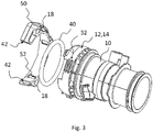
- Figure 3 depicts an exploded view of the part of the duct connection of Figure 1 with the first duct 10, the bracket 50 and a sealing means 40, e.g. a toroidal ring in this embodiment.
- the bracket 50 encloses the first duct 10 in a circumferential direction by an angle close to 180°, so to be easily clipped onto the first duct 10.
- the bracket 50 is made of plastics material, in particular of a thermoplastics material.
- the bracket 50 comprises a ring-segment shaped body 60 provided with bracket interface segment 52.
- the bracket interface segment 52 is configured to cooperate with a duct interface segment 12 of the duct 10.
- the duct interface segment 12 is located on one end of the first duct 10.
- the interface segment 12 is configured to cooperate with a complementary bracket interface segment 52.
- the duct interface segment 12 is arranged on an outer face of the first duct 10 and, in this embodiment, surrounds the end of the first duct 10.
- stopping means 32 are provided on duct 10 as well as stopping means 42 on the bracket 50.
- Figure 4 illustrates in a cut view a duct connection 100 between two ducts 10, 20 according to an embodiment of the invention.
- Figure 5 highlights in a cut view a detail of the duct connection 100 of Figure 4 .
- the duct connection 100 may be part of an air duct 110 of an internal combustion engine which consist of ducts made from plastics material.
- the duct connection may comprise a first duct 10 as described in the Figures 1 to 3 comprising a bracket 50 and a duct interface segment 12.
- the second duct 20 provides an axially direction 30 which may be an axial direction of the first duct 10.
- the second duct 20 comprises a flange 22 located on one end of said second duct 20, which encloses a front end 26 of the second duct 20 in a circumferential direction.
- a groove 24 is arranged between the inner face of the flange 22 and the outer face of the front end 26 for receiving at least a part of the first duct 10, in particular for receiving a part of the duct interface segment 12 of the first duct 10.
- the front end 26 of the second duct 20 is inserted into the first bracket 10 so that the outer face of the front end 26 is radially spaced from the inner face of the outer face of the first duct 10, forming a groove 19.
- the groove 19 is configured for receiving a sealing means 40.
- the sealing means 40 is provided for sealing the connection between the two ducts 10, 20 and may be a toroidal ring.
- the sealing means 40 provides radial sealing between the first duct 10 and the second duct 20 and may also provide axial sealing between the two ducts 10, 20.
- the first duct 10 comprises a step 16 at its inner face which reduces the aperture of the end of the first duct 10.
- the step 16 may serve as a sealing surface for the sealing means 40.
- the bracket 50 is mounted, in particular clipped, to the first duct 10 and fastened to the flange 22 of the second duct 20.
- the bracket provides through holes 18 for receiving fastening means such as screws (not shown).
- fastening means such as screws (not shown).
- metallic inserts may be arranged in the through holes 18.
- the duct interface segment 12 is located on one end of said first duct 10, the interface segment 12 being configured to cooperate with a complementary bracket interface segment 52.
- the duct interface segment 12 and the bracket interface segment 52 have complementary contact surfaces 14, 54, which are curved, in particular spherically shaped, in axial direction 30.
- the duct interface segment 12 is arranged on the outer face of the first duct 10.
- the bracket interface segment 52 is arranged on the inner face of the bracket 50.
- the duct interface segment 12 is configured, in a radial direction, with a convex contact surface 14 and the bracket interface segment 52 is configured with a concave contact surface 54.
- the tilt angle may be limited by the tip of the front end 26 of the second duct 20 which serves as a stopping means for limiting the tilt angle.
- the duct interface segment 12 surrounds the end of the first duct 10 and the bracket interface segment 52 surrounds the front end 26 of the second duct 20.
- the duct interface segment 12 may be configured, in radial direction, with a concave contact surface 14 and the bracket interface segment 52 may be configured with a convex contact surface 54.
Landscapes
- Engineering & Computer Science (AREA)
- General Engineering & Computer Science (AREA)
- Mechanical Engineering (AREA)
- Chemical & Material Sciences (AREA)
- Combustion & Propulsion (AREA)
- Gasket Seals (AREA)
- Quick-Acting Or Multi-Walled Pipe Joints (AREA)
Abstract
Description
- The invention relates to an arrangement for fastening ducts for carrying a fluid. More particularly, the invention relates to a sealed connection between two ducts, such as pipes, valves and other flow devices, in particular of an internal combustion engine, particular of a motor vehicle or a stationary engine. More particularly, the invention relates to an arrangement for fastening ducts for carrying air, in particular charged air.
- In an internal combustion engine the parts of an air intake system are submitted to strong thermo-mechanical stress as the engine warms up, in particular at the level of the connecting elements between parts. For instance, the metallic outlet flange of a turbo compressor is classically fitted to the flange of a thermoplastic duct using a flat flange connection. Such a connection comprises screws which are placed through symmetrically disposed holes in the flange of each part and an axial sealing gasket such as, e.g., an O-ring, which is compressed between the flanges in order to seal the connection axially. In other words, the screws ensure mechanical assembly of the abutting flanges, and the axial sealing gasket is used to ensure the tightness of the flat flange connection of the metallic and plastic parts. Any deformation of the plastic flange of the duct, due in particular to pressure, temperature, mechanical stresses and creeping, generates a loss of sealing compression, and thus a risk of leakage.
-
EP 2832984 A1 discloses an improved connection arrangement between two ducts which are connected by a flange which can tolerate deformations of the connected ducts thus preventing leakages. - It is an object of the invention to provide a duct connection between two ducts which allows for a relative rotational movement between the ducts when the connection is closed.
- Another object of the invention is to provide a fastening means for such a duct connection.
- Another object of the invention is to provide a duct comprising such a duct connection.
- Favorably, the claimed duct connection can be used for air ducts, particularly charged air ducts, particular at the air intake system of an internal combustion engine, between a turbo charger or compressor and an intake of an engine.
- In a first aspect of the invention one object is achieved by a duct connection between a first duct and a second duct of an engine, in particular where at least one of the two ducts is made of a plastics material, comprising a flange located on one end of said second duct; a sealing means for sealing the connection between the two ducts; a bracket mounted to the first duct and fastened to the flange of the second duct; and a duct interface segment located on one end of said first duct, the interface segment being configured to cooperate with a complementary bracket interface segment.
- According to the invention, the duct interface segment and the bracket interface segment have complementary contact surfaces, which are curved, in particular spherically shaped, in an axial direction. The curvature of the interface brackets in axial direction favorably locks the first duct axially in relation to the second duct.
- In another aspect of the invention one object is achieved by a bracket for a duct connection according to the invention, comprising a ring-segment shaped body provided with a bracket interface segment for cooperating with a duct interface segment of a duct.
- A duct connection between a first duct and a second duct, particularly of an internal combustion engine, is proposed, in particular where at least one of the two ducts is made of a plastics material, comprising a flange located on one end of said second duct; a sealing means for sealing the connection between the two ducts; a bracket mounted to the first duct and fastened to the flange of the second duct; and a duct interface segment located on one end of said first duct, the interface segment being configured to cooperate with a complementary bracket interface segment.
- Advantageously, the ducts and the bracket may be made of plastics material, in particular thermoplastic material.
- Advantageously, the bracket may be clipped on the first duct and fastened to the flange by fastening means such as screws. Sealing can be provided separately from the mechanical connection between the bracket and the second duct. The bracket locks the first duct in an axial direction.
- By mounting, e.g. clipping, the bracket to the first duct and fastening, e.g. via screws, the bracket to the flange of the second duct the first duct is capable of rotational movements within certain limits even when the connection is closed, while relative axial movements between the ducts are blocked. Depending on the shape of the interface segments it may even be possible to allow for tilting one of the ducts with respect to the other one in certain limits of a tilt angle. For instance a tilt angle may be limited to not more than 15°, preferably by not more than 10°. A stopping means may be provided for limiting a tilt angle to any value as needed.
- According to a favorable embodiment of the duct connection, the duct interface segment may be arranged on an outer face of the first duct and the bracket interface segment may be arranged on an inner face of the bracket. In particular, the duct interface segment may surround the end of the first duct. Additionally or alternatively, the bracket interface segment may surround a front end of the second duct. This facilitates the mounting of the ducts in the connection as the mutual rotational positions of the interface segments can be selected at random. Alternatively, one or both of the interface segments may be composed of one or more localized areas on the respective faces of the ducts.
- According to a favorable embodiment of the duct connection, the flange may enclose a front end of the second duct in a circumferential direction providing a groove for receiving at least a part of the first duct. In particular, the groove may be provided for receiving a part of the duct interface segment of the first duct. Advantageously, the front end of the second duct may provide a sealing area and/or a sealing groove for the sealing means. For instance, the sealing means can be arranged between the outer face of the second duct and the inner face of the first duct.
- According to a favorable embodiment of the duct connection, a front end of the second duct may be inserted into the first duct. Mounting of the ducts is facilitated.
- According to a favorable embodiment of the duct connection, the bracket may enclose the first duct by an angle in a circumferential direction of less than 360°. The angle of enclosure must be managed by the raw material used for the bracket and the capacity of the bracket to accept a deformation during the assembly on the duct, which happens, however, only once time. The higher the angle the higher the risk of breakage. Nevertheless, if the angle is lower than 180°, there is a risk of pull off the bracket during lifetime. For instance, the angle may be close to 180°. Hence, a skilled person will choose the angle of enclosure appropriately. In one embodiment, for instance, the bracket may enclose the first duct in a circumferential direction by not more than 210°, preferably by at least 180°. Favorably, the bracket can be clipped on the first duct easily.
- According to a favorable embodiment of the duct connection, the duct interface segment may be configured with a convex contact surface and the bracket interface segment may be configured with a concave contact surface. Alternatively, the duct interface segment may be configured with a concave contact surface and the bracket interface segment may be configured with a convex contact surface. By providing the duct interface segment with a convex contact surface and the bracket interface segment with a concave contact surface a tilt angle between the first and second duct can be achieved.
- According to a favorable embodiment of the duct connection, the bracket may be made of plastics material, in particular of a thermoplastics material. The plastics material may be a thermoplastic material, e.g. polyamide or polypropylene, particularly filled with glasfibers and/or minerals.
- According to a favorable embodiment of the duct connection, the sealing means may be arranged in a sealing groove of the second duct. In particular, the sealing means may comprise an annular seal. However, it is to be understood that various shapes and kinds of seals may be used, such as flat rings, lip seals can be used.
- The sealing means may be sandwiched between the abutted front ends of the ducts. The sealing areas ensure axial and radial tightness and increased leakage resistance in the region of the junction of the connected ducts.
- Sealing is achieved using a sealing gasket being fitted between the ducts. Such a connection is also easy to assemble and quickly detachable, and compatible with current flange designs for combustion engines, particular in the automotive industry.
- According to a favorable embodiment of the duct connection, a stopping means is provided for limiting a relative tilt angle between the ducts to not more than 10° or any value as needed. For instance, as the second duct is inserted into the first duct, the front end of the second duct may serve as a stopping means. However it is to be understood that various stopping means can be provided.
- According to another object of the invention a bracket for a duct connection according to the invention is proposed, comprising a ring-segment shaped body provided with a bracket interface segment for cooperating with a duct interface segment of a duct.
- The bracket may be made of plastics material, in particular of a thermoplastics material. The plastics material may be a thermoplastic material, e.g. polyamide or polypropylene, particularly filled with glasfibers and/or minerals. The bracket may be provided with an inner face having a curved shape in an axial direction. The bracket may have the form of a ring segment so that the bracket may enclose the first duct by an angle in a circumferential direction of less than 360°. The angle of enclosure must be managed by the raw material used for the bracket and the capacity of the bracket to accept a deformation during the assembly on the duct, which happens, however, only once time. The higher the angle the higher the risk of breakage. Nevertheless, if the angle is lower than 180°, there is a risk of pull off the bracket during lifetime. For instance, the angle may be close to 180°. In one embodiment, for instance, the bracket may enclose the first duct in a circumferential direction by not more than 210°, preferably by at least 180°. Favorably, the bracket can be clipped on the first duct easily.
- According to another object of the invention, a duct comprising a duct connection is proposed with the duct connection between a first duct and a second duct of an engine, in particular where at least one of the two ducts is made of a plastics material, comprising a flange located on one end of said second duct; a sealing means for sealing the connection between the two ducts; a bracket mounted to the first duct and fastened to the flange of the second duct; and a duct interface segment located on one end of said first duct, the interface segment being configured to cooperate with a complementary bracket interface segment.
- Favorably, the flange may be made of plastics material. Favorably, the bracket may be made of a plastics material. Favorably, one or both ducts may be made of a plastics material. The plastics material may be a thermoplastic material, e.g. polyamide or polypropylene, particularly filled with glass fibers and/or minerals.
- The present invention together with the above-mentioned and other objects and advantages may best be understood from the following detailed description of the embodiments, but not restricted to the embodiments, wherein is shown in:
- Figure 1
- a perspective view of a part of a duct connection featuring a first duct and a bracket clipped on the first duct according to an embodiment of the invention;
- Figure 2
- a perspective view of the bracket shown in
Figure 1 ; - Figure 3
- in an exploded view the part of the duct connection of
Figure 1 ; - Figure 4
- in a cut view a duct connection between two ducts according to an embodiment of the invention;
- Figure 5
- in a cut view a detail of the duct connection of
Figure 4 . - In the drawings, like elements are referred to with equal reference numerals. The drawings are merely schematic representations, not intended to portray specific parameters of the invention. Moreover, the drawings are intended to depict only typical embodiments of the invention and therefore should not be considered as limiting the scope of the invention.
-
Figure 1 depicts in a perspective view a part of a duct connection 100 (Figure 5 ), featuring afirst duct 10 and abracket 50 clipped on thefirst duct 10 according to an embodiment of the invention.Figure 2 displays a perspective view of thebracket 50 shown inFigure 1 .Figure 3 depicts an exploded view of the part of the duct connection ofFigure 1 with thefirst duct 10, thebracket 50 and a sealing means 40, e.g. a toroidal ring in this embodiment. - In this embodiment, the
bracket 50 encloses thefirst duct 10 in a circumferential direction by an angle close to 180°, so to be easily clipped onto thefirst duct 10. Of course, in other embodiments other angles of enclosure may be chosen. Preferably, thebracket 50 is made of plastics material, in particular of a thermoplastics material. - The
bracket 50 comprises a ring-segment shapedbody 60 provided withbracket interface segment 52. Thebracket interface segment 52 is configured to cooperate with aduct interface segment 12 of theduct 10. - The
duct interface segment 12 is located on one end of thefirst duct 10. Theinterface segment 12 is configured to cooperate with a complementarybracket interface segment 52. Theduct interface segment 12 is arranged on an outer face of thefirst duct 10 and, in this embodiment, surrounds the end of thefirst duct 10. In order to limit a rotational movement between the twoducts 10, 20 (Figures 4, 5 ) when the axes of the ducts are aligned at least at their mutual interface region, stopping means 32 are provided onduct 10 as well as stoppingmeans 42 on thebracket 50. -
Figure 4 illustrates in a cut view aduct connection 100 between twoducts Figure 5 highlights in a cut view a detail of theduct connection 100 ofFigure 4 . - The
duct connection 100 may be part of anair duct 110 of an internal combustion engine which consist of ducts made from plastics material. - In particular, the duct connection may comprise a
first duct 10 as described in theFigures 1 to 3 comprising abracket 50 and aduct interface segment 12. Thesecond duct 20 provides anaxially direction 30 which may be an axial direction of thefirst duct 10. - The
second duct 20 comprises aflange 22 located on one end of saidsecond duct 20, which encloses afront end 26 of thesecond duct 20 in a circumferential direction. Agroove 24 is arranged between the inner face of theflange 22 and the outer face of thefront end 26 for receiving at least a part of thefirst duct 10, in particular for receiving a part of theduct interface segment 12 of thefirst duct 10. - The
front end 26 of thesecond duct 20 is inserted into thefirst bracket 10 so that the outer face of thefront end 26 is radially spaced from the inner face of the outer face of thefirst duct 10, forming agroove 19. Thegroove 19 is configured for receiving a sealing means 40. - The sealing means 40 is provided for sealing the connection between the two
ducts first duct 10 and thesecond duct 20 and may also provide axial sealing between the twoducts first duct 10 comprises astep 16 at its inner face which reduces the aperture of the end of thefirst duct 10. Thestep 16 may serve as a sealing surface for the sealing means 40. - The
bracket 50 is mounted, in particular clipped, to thefirst duct 10 and fastened to theflange 22 of thesecond duct 20. The bracket provides throughholes 18 for receiving fastening means such as screws (not shown). For better stability, in particular metallic inserts (not shown) may be arranged in the through holes 18. - The
duct interface segment 12 is located on one end of saidfirst duct 10, theinterface segment 12 being configured to cooperate with a complementarybracket interface segment 52. - The
duct interface segment 12 and thebracket interface segment 52 have complementary contact surfaces 14, 54, which are curved, in particular spherically shaped, inaxial direction 30. - The
duct interface segment 12 is arranged on the outer face of thefirst duct 10. Thebracket interface segment 52 is arranged on the inner face of thebracket 50. - In this embodiment the
duct interface segment 12 is configured, in a radial direction, with aconvex contact surface 14 and thebracket interface segment 52 is configured with aconcave contact surface 54. - This allows for a tilt angle of a few degrees between the two
ducts axial direction 30 of thesecond duct 20 and an axial direction of thefirst duct 10. The tilt angle may be limited by the tip of thefront end 26 of thesecond duct 20 which serves as a stopping means for limiting the tilt angle. - In particular the
duct interface segment 12 surrounds the end of thefirst duct 10 and thebracket interface segment 52 surrounds thefront end 26 of thesecond duct 20. - Alternatively, in an embodiment not illustrated, the
duct interface segment 12 may be configured, in radial direction, with aconcave contact surface 14 and thebracket interface segment 52 may be configured with aconvex contact surface 54. -
- 10
- first duct
- 12
- duct interface segment
- 14
- contact surface
- 16
- step
- 18
- through hole
- 19
- groove
- 20
- second duct
- 22
- flange
- 24
- groove
- 26
- front end
- 30
- axial direction
- 32
- stopping means
- 40
- sealing means
- 42
- stopping means
- 50
- bracket
- 52
- bracket interface segment
- 54
- contact surface
- 60
- body
- 100
- duct connection
- 110
- air duct
Claims (11)
- A duct connection (100) between a first duct (10) and a second duct (20), in particular of an internal combustion engine, in particular where at least one of the two ducts (10, 20) is made of a plastics material, comprising
a flange (22) located on one end of said second duct (20),
a sealing means (40) for sealing the connection between the two ducts (10, 20);
a bracket (50) mounted to the first duct (10) and fastened to the flange (22) of the second duct (20); and
a duct interface segment (12) located on one end of said first duct (10), the interface segment (12) being configured to cooperate with a complementary bracket interface segment (52),
wherein the duct interface segment (12) and the bracket interface segment (52) have complementary contact surfaces (14, 54), which are curved, in particular spherically shaped, in an axial direction (30). - The duct connection according to claim 1, wherein the duct interface segment (12) is arranged on an outer face of the first duct (10) and the bracket interface segment (52) is arranged on an inner face of the bracket (50), in particular wherein the duct interface segment (12) surrounds the end of the first duct (10) and/or the bracket interface segment (52) surrounds a front end (26) of the second duct (20).
- The duct connection according to claim 1 or 2, wherein the flange (22) encloses a front end (26) of the second duct (20) in a circumferential direction providing a groove (24) for receiving at least a part of the first duct (10), in particular for receiving a part of the duct interface segment (12) of the first duct (10).
- The duct connection according to any one of the preceding claims, wherein a front end (26) of the second duct (20) is inserted into the first duct (10).
- The duct connection according to any one of the preceding claims, wherein the bracket (50) encloses the first duct (10) by an angle in a circumferential direction by less than 360°.
- The duct connection according to any one of the preceding claims, wherein the duct interface segment (12) is configured with a convex contact surface (14) and the bracket interface segment (52) is configured with a concave contact surface (54), or
wherein the duct interface segment (12) is configured with a concave contact surface (14) and the bracket interface segment (52) is configured with a convex contact surface (54). - The duct connection according to any one of the preceding claims, wherein the bracket (50) is made of plastics material, in particular of a thermoplastics material.
- The duct connection according to any one of the preceding claims, wherein the sealing means (40) is arranged in a sealing groove of the first duct (10), in particular wherein said sealing means (40) comprise an annular seal.
- The duct connection according to any one of the preceding claims, wherein a stopping means is provided for limiting a relative tilt angle between the ducts (10, 20).
- A bracket (50) for a duct connection (100) according to any one of the preceding claims, comprising a ring-segment shaped body (60) provided with a bracket interface segment (52) for cooperating with a duct interface segment (12) of a duct (10).
- A duct (110) comprising a duct connection (100) according to any one of the claims 1 to 9.
Priority Applications (2)
| Application Number | Priority Date | Filing Date | Title |
|---|---|---|---|
| ES20290065T ES2992755T3 (en) | 2020-09-25 | 2020-09-25 | Duct connection |
| EP20290065.0A EP3974695B1 (en) | 2020-09-25 | 2020-09-25 | Duct connection |
Applications Claiming Priority (1)
| Application Number | Priority Date | Filing Date | Title |
|---|---|---|---|
| EP20290065.0A EP3974695B1 (en) | 2020-09-25 | 2020-09-25 | Duct connection |
Publications (2)
| Publication Number | Publication Date |
|---|---|
| EP3974695A1 true EP3974695A1 (en) | 2022-03-30 |
| EP3974695B1 EP3974695B1 (en) | 2024-06-12 |
Family
ID=73014449
Family Applications (1)
| Application Number | Title | Priority Date | Filing Date |
|---|---|---|---|
| EP20290065.0A Active EP3974695B1 (en) | 2020-09-25 | 2020-09-25 | Duct connection |
Country Status (2)
| Country | Link |
|---|---|
| EP (1) | EP3974695B1 (en) |
| ES (1) | ES2992755T3 (en) |
Cited By (1)
| Publication number | Priority date | Publication date | Assignee | Title |
|---|---|---|---|---|
| US20220186864A1 (en) * | 2020-12-11 | 2022-06-16 | Mann+Hummel Gmbh | Coupling Assembly for Pipes |
Citations (5)
| Publication number | Priority date | Publication date | Assignee | Title |
|---|---|---|---|---|
| US3165339A (en) * | 1961-05-25 | 1965-01-12 | Fmc Corp | Swivel pipe coupling |
| GB1164213A (en) * | 1966-03-23 | 1969-09-17 | Mancar Trust | A pipe union. |
| DE2547755A1 (en) * | 1975-10-24 | 1977-04-28 | Leykam Muerztaler Papier | Plastics pipe connector sleeve - is split doubly concave shell with band and bolt edge joints for beaded pipes |
| EP2832984A1 (en) | 2013-07-29 | 2015-02-04 | MANN+HUMMEL GmbH | Flange connection |
| EP3699473A1 (en) * | 2019-02-20 | 2020-08-26 | Akwel Vannes France | Device for articulated connection of two tubular components |
-
2020
- 2020-09-25 EP EP20290065.0A patent/EP3974695B1/en active Active
- 2020-09-25 ES ES20290065T patent/ES2992755T3/en active Active
Patent Citations (5)
| Publication number | Priority date | Publication date | Assignee | Title |
|---|---|---|---|---|
| US3165339A (en) * | 1961-05-25 | 1965-01-12 | Fmc Corp | Swivel pipe coupling |
| GB1164213A (en) * | 1966-03-23 | 1969-09-17 | Mancar Trust | A pipe union. |
| DE2547755A1 (en) * | 1975-10-24 | 1977-04-28 | Leykam Muerztaler Papier | Plastics pipe connector sleeve - is split doubly concave shell with band and bolt edge joints for beaded pipes |
| EP2832984A1 (en) | 2013-07-29 | 2015-02-04 | MANN+HUMMEL GmbH | Flange connection |
| EP3699473A1 (en) * | 2019-02-20 | 2020-08-26 | Akwel Vannes France | Device for articulated connection of two tubular components |
Cited By (2)
| Publication number | Priority date | Publication date | Assignee | Title |
|---|---|---|---|---|
| US20220186864A1 (en) * | 2020-12-11 | 2022-06-16 | Mann+Hummel Gmbh | Coupling Assembly for Pipes |
| US11815205B2 (en) * | 2020-12-11 | 2023-11-14 | Mann+Hummel Gmbh | Coupling assembly for pipes |
Also Published As
| Publication number | Publication date |
|---|---|
| EP3974695B1 (en) | 2024-06-12 |
| ES2992755T3 (en) | 2024-12-17 |
Similar Documents
| Publication | Publication Date | Title |
|---|---|---|
| KR101287912B1 (en) | Exhaust pipe for a motor vehicle and exhaust system | |
| US9863262B2 (en) | Sealing structure for turbocharger housing | |
| US7556295B2 (en) | Axial and radial play and angle compensation of a tolerating pipe connection | |
| CN115380182B (en) | Plug valve hard seal on cylindrical wall | |
| EP2055911A1 (en) | Exhaust turbo-charger | |
| CA2113878C (en) | Shaft seal and bore assembly | |
| US10527208B2 (en) | Composite seal for rapid fluid-transfer coupling, and coupling of this type | |
| US20240301958A1 (en) | Seal and fluid valve having such a seal | |
| US6886834B2 (en) | Shaft sealing assembly | |
| EP3770470A1 (en) | Seal ring | |
| JP6999068B2 (en) | Seal ring | |
| WO1990006435A1 (en) | Multi-layer lip seal assembly | |
| US20100300569A1 (en) | Corrugated hose | |
| US20130341873A1 (en) | Radial Shaft Seal Ring | |
| EP3974695B1 (en) | Duct connection | |
| EP3875810B1 (en) | Sealing device | |
| US10816100B2 (en) | Sealing member for a multi-direction changeover valve and a multi-direction changeover valve including the sealing member | |
| EP2832984B1 (en) | Flange connection | |
| WO2024018751A1 (en) | Sealing structure | |
| US12631254B2 (en) | Sealing device and sealing structure | |
| EP4174347A1 (en) | Ball valve system with ball mounted seal | |
| US11493132B2 (en) | Sealing device | |
| US20070040379A1 (en) | Connection assembly and related method | |
| KR20250168318A (en) | Pipe connection port and pipe connection method using the same | |
| JP2025021606A (en) | Sealing device |
Legal Events
| Date | Code | Title | Description |
|---|---|---|---|
| PUAI | Public reference made under article 153(3) epc to a published international application that has entered the european phase |
Free format text: ORIGINAL CODE: 0009012 |
|
| STAA | Information on the status of an ep patent application or granted ep patent |
Free format text: STATUS: THE APPLICATION HAS BEEN PUBLISHED |
|
| AK | Designated contracting states |
Kind code of ref document: A1 Designated state(s): AL AT BE BG CH CY CZ DE DK EE ES FI FR GB GR HR HU IE IS IT LI LT LU LV MC MK MT NL NO PL PT RO RS SE SI SK SM TR |
|
| STAA | Information on the status of an ep patent application or granted ep patent |
Free format text: STATUS: REQUEST FOR EXAMINATION WAS MADE |
|
| 17P | Request for examination filed |
Effective date: 20220929 |
|
| RBV | Designated contracting states (corrected) |
Designated state(s): AL AT BE BG CH CY CZ DE DK EE ES FI FR GB GR HR HU IE IS IT LI LT LU LV MC MK MT NL NO PL PT RO RS SE SI SK SM TR |
|
| STAA | Information on the status of an ep patent application or granted ep patent |
Free format text: STATUS: EXAMINATION IS IN PROGRESS |
|
| 17Q | First examination report despatched |
Effective date: 20230227 |
|
| GRAP | Despatch of communication of intention to grant a patent |
Free format text: ORIGINAL CODE: EPIDOSNIGR1 |
|
| STAA | Information on the status of an ep patent application or granted ep patent |
Free format text: STATUS: GRANT OF PATENT IS INTENDED |
|
| INTG | Intention to grant announced |
Effective date: 20240205 |
|
| GRAS | Grant fee paid |
Free format text: ORIGINAL CODE: EPIDOSNIGR3 |
|
| GRAA | (expected) grant |
Free format text: ORIGINAL CODE: 0009210 |
|
| STAA | Information on the status of an ep patent application or granted ep patent |
Free format text: STATUS: THE PATENT HAS BEEN GRANTED |
|
| AK | Designated contracting states |
Kind code of ref document: B1 Designated state(s): AL AT BE BG CH CY CZ DE DK EE ES FI FR GB GR HR HU IE IS IT LI LT LU LV MC MK MT NL NO PL PT RO RS SE SI SK SM TR |
|
| REG | Reference to a national code |
Ref country code: GB Ref legal event code: FG4D |
|
| REG | Reference to a national code |
Ref country code: CH Ref legal event code: EP |
|
| REG | Reference to a national code |
Ref country code: DE Ref legal event code: R096 Ref document number: 602020032256 Country of ref document: DE |
|
| REG | Reference to a national code |
Ref country code: IE Ref legal event code: FG4D |
|
| P01 | Opt-out of the competence of the unified patent court (upc) registered |
Free format text: CASE NUMBER: APP_40830/2024 Effective date: 20240710 |
|
| PG25 | Lapsed in a contracting state [announced via postgrant information from national office to epo] |
Ref country code: BG Free format text: LAPSE BECAUSE OF FAILURE TO SUBMIT A TRANSLATION OF THE DESCRIPTION OR TO PAY THE FEE WITHIN THE PRESCRIBED TIME-LIMIT Effective date: 20240612 |
|
| PG25 | Lapsed in a contracting state [announced via postgrant information from national office to epo] |
Ref country code: FI Free format text: LAPSE BECAUSE OF FAILURE TO SUBMIT A TRANSLATION OF THE DESCRIPTION OR TO PAY THE FEE WITHIN THE PRESCRIBED TIME-LIMIT Effective date: 20240612 Ref country code: HR Free format text: LAPSE BECAUSE OF FAILURE TO SUBMIT A TRANSLATION OF THE DESCRIPTION OR TO PAY THE FEE WITHIN THE PRESCRIBED TIME-LIMIT Effective date: 20240612 |
|
| REG | Reference to a national code |
Ref country code: LT Ref legal event code: MG9D |
|
| PG25 | Lapsed in a contracting state [announced via postgrant information from national office to epo] |
Ref country code: GR Free format text: LAPSE BECAUSE OF FAILURE TO SUBMIT A TRANSLATION OF THE DESCRIPTION OR TO PAY THE FEE WITHIN THE PRESCRIBED TIME-LIMIT Effective date: 20240913 |
|
| REG | Reference to a national code |
Ref country code: NL Ref legal event code: MP Effective date: 20240612 |
|
| PG25 | Lapsed in a contracting state [announced via postgrant information from national office to epo] |
Ref country code: LV Free format text: LAPSE BECAUSE OF FAILURE TO SUBMIT A TRANSLATION OF THE DESCRIPTION OR TO PAY THE FEE WITHIN THE PRESCRIBED TIME-LIMIT Effective date: 20240612 |
|
| PG25 | Lapsed in a contracting state [announced via postgrant information from national office to epo] |
Ref country code: NO Free format text: LAPSE BECAUSE OF FAILURE TO SUBMIT A TRANSLATION OF THE DESCRIPTION OR TO PAY THE FEE WITHIN THE PRESCRIBED TIME-LIMIT Effective date: 20240912 Ref country code: LV Free format text: LAPSE BECAUSE OF FAILURE TO SUBMIT A TRANSLATION OF THE DESCRIPTION OR TO PAY THE FEE WITHIN THE PRESCRIBED TIME-LIMIT Effective date: 20240612 Ref country code: HR Free format text: LAPSE BECAUSE OF FAILURE TO SUBMIT A TRANSLATION OF THE DESCRIPTION OR TO PAY THE FEE WITHIN THE PRESCRIBED TIME-LIMIT Effective date: 20240612 Ref country code: GR Free format text: LAPSE BECAUSE OF FAILURE TO SUBMIT A TRANSLATION OF THE DESCRIPTION OR TO PAY THE FEE WITHIN THE PRESCRIBED TIME-LIMIT Effective date: 20240913 Ref country code: FI Free format text: LAPSE BECAUSE OF FAILURE TO SUBMIT A TRANSLATION OF THE DESCRIPTION OR TO PAY THE FEE WITHIN THE PRESCRIBED TIME-LIMIT Effective date: 20240612 Ref country code: BG Free format text: LAPSE BECAUSE OF FAILURE TO SUBMIT A TRANSLATION OF THE DESCRIPTION OR TO PAY THE FEE WITHIN THE PRESCRIBED TIME-LIMIT Effective date: 20240612 Ref country code: RS Free format text: LAPSE BECAUSE OF FAILURE TO SUBMIT A TRANSLATION OF THE DESCRIPTION OR TO PAY THE FEE WITHIN THE PRESCRIBED TIME-LIMIT Effective date: 20240912 |
|
| PG25 | Lapsed in a contracting state [announced via postgrant information from national office to epo] |
Ref country code: NL Free format text: LAPSE BECAUSE OF FAILURE TO SUBMIT A TRANSLATION OF THE DESCRIPTION OR TO PAY THE FEE WITHIN THE PRESCRIBED TIME-LIMIT Effective date: 20240612 |
|
| REG | Reference to a national code |
Ref country code: AT Ref legal event code: MK05 Ref document number: 1694536 Country of ref document: AT Kind code of ref document: T Effective date: 20240612 |
|
| PG25 | Lapsed in a contracting state [announced via postgrant information from national office to epo] |
Ref country code: NL Free format text: LAPSE BECAUSE OF FAILURE TO SUBMIT A TRANSLATION OF THE DESCRIPTION OR TO PAY THE FEE WITHIN THE PRESCRIBED TIME-LIMIT Effective date: 20240612 |
|
| PG25 | Lapsed in a contracting state [announced via postgrant information from national office to epo] |
Ref country code: PT Free format text: LAPSE BECAUSE OF FAILURE TO SUBMIT A TRANSLATION OF THE DESCRIPTION OR TO PAY THE FEE WITHIN THE PRESCRIBED TIME-LIMIT Effective date: 20241014 |
|
| REG | Reference to a national code |
Ref country code: ES Ref legal event code: FG2A Ref document number: 2992755 Country of ref document: ES Kind code of ref document: T3 Effective date: 20241217 |
|
| PG25 | Lapsed in a contracting state [announced via postgrant information from national office to epo] |
Ref country code: PT Free format text: LAPSE BECAUSE OF FAILURE TO SUBMIT A TRANSLATION OF THE DESCRIPTION OR TO PAY THE FEE WITHIN THE PRESCRIBED TIME-LIMIT Effective date: 20241014 |
|
| PG25 | Lapsed in a contracting state [announced via postgrant information from national office to epo] |
Ref country code: PL Free format text: LAPSE BECAUSE OF FAILURE TO SUBMIT A TRANSLATION OF THE DESCRIPTION OR TO PAY THE FEE WITHIN THE PRESCRIBED TIME-LIMIT Effective date: 20240612 |
|
| PG25 | Lapsed in a contracting state [announced via postgrant information from national office to epo] |
Ref country code: EE Free format text: LAPSE BECAUSE OF FAILURE TO SUBMIT A TRANSLATION OF THE DESCRIPTION OR TO PAY THE FEE WITHIN THE PRESCRIBED TIME-LIMIT Effective date: 20240612 |
|
| PG25 | Lapsed in a contracting state [announced via postgrant information from national office to epo] |
Ref country code: AT Free format text: LAPSE BECAUSE OF FAILURE TO SUBMIT A TRANSLATION OF THE DESCRIPTION OR TO PAY THE FEE WITHIN THE PRESCRIBED TIME-LIMIT Effective date: 20240612 Ref country code: IS Free format text: LAPSE BECAUSE OF FAILURE TO SUBMIT A TRANSLATION OF THE DESCRIPTION OR TO PAY THE FEE WITHIN THE PRESCRIBED TIME-LIMIT Effective date: 20241012 |
|
| PG25 | Lapsed in a contracting state [announced via postgrant information from national office to epo] |
Ref country code: CZ Free format text: LAPSE BECAUSE OF FAILURE TO SUBMIT A TRANSLATION OF THE DESCRIPTION OR TO PAY THE FEE WITHIN THE PRESCRIBED TIME-LIMIT Effective date: 20240612 |
|
| PG25 | Lapsed in a contracting state [announced via postgrant information from national office to epo] |
Ref country code: SK Free format text: LAPSE BECAUSE OF FAILURE TO SUBMIT A TRANSLATION OF THE DESCRIPTION OR TO PAY THE FEE WITHIN THE PRESCRIBED TIME-LIMIT Effective date: 20240612 Ref country code: RO Free format text: LAPSE BECAUSE OF FAILURE TO SUBMIT A TRANSLATION OF THE DESCRIPTION OR TO PAY THE FEE WITHIN THE PRESCRIBED TIME-LIMIT Effective date: 20240612 |
|
| PG25 | Lapsed in a contracting state [announced via postgrant information from national office to epo] |
Ref country code: SM Free format text: LAPSE BECAUSE OF FAILURE TO SUBMIT A TRANSLATION OF THE DESCRIPTION OR TO PAY THE FEE WITHIN THE PRESCRIBED TIME-LIMIT Effective date: 20240612 |
|
| PG25 | Lapsed in a contracting state [announced via postgrant information from national office to epo] |
Ref country code: SM Free format text: LAPSE BECAUSE OF FAILURE TO SUBMIT A TRANSLATION OF THE DESCRIPTION OR TO PAY THE FEE WITHIN THE PRESCRIBED TIME-LIMIT Effective date: 20240612 Ref country code: SK Free format text: LAPSE BECAUSE OF FAILURE TO SUBMIT A TRANSLATION OF THE DESCRIPTION OR TO PAY THE FEE WITHIN THE PRESCRIBED TIME-LIMIT Effective date: 20240612 Ref country code: RO Free format text: LAPSE BECAUSE OF FAILURE TO SUBMIT A TRANSLATION OF THE DESCRIPTION OR TO PAY THE FEE WITHIN THE PRESCRIBED TIME-LIMIT Effective date: 20240612 Ref country code: PL Free format text: LAPSE BECAUSE OF FAILURE TO SUBMIT A TRANSLATION OF THE DESCRIPTION OR TO PAY THE FEE WITHIN THE PRESCRIBED TIME-LIMIT Effective date: 20240612 Ref country code: IS Free format text: LAPSE BECAUSE OF FAILURE TO SUBMIT A TRANSLATION OF THE DESCRIPTION OR TO PAY THE FEE WITHIN THE PRESCRIBED TIME-LIMIT Effective date: 20241012 Ref country code: EE Free format text: LAPSE BECAUSE OF FAILURE TO SUBMIT A TRANSLATION OF THE DESCRIPTION OR TO PAY THE FEE WITHIN THE PRESCRIBED TIME-LIMIT Effective date: 20240612 Ref country code: CZ Free format text: LAPSE BECAUSE OF FAILURE TO SUBMIT A TRANSLATION OF THE DESCRIPTION OR TO PAY THE FEE WITHIN THE PRESCRIBED TIME-LIMIT Effective date: 20240612 Ref country code: AT Free format text: LAPSE BECAUSE OF FAILURE TO SUBMIT A TRANSLATION OF THE DESCRIPTION OR TO PAY THE FEE WITHIN THE PRESCRIBED TIME-LIMIT Effective date: 20240612 |
|
| PG25 | Lapsed in a contracting state [announced via postgrant information from national office to epo] |
Ref country code: IT Free format text: LAPSE BECAUSE OF FAILURE TO SUBMIT A TRANSLATION OF THE DESCRIPTION OR TO PAY THE FEE WITHIN THE PRESCRIBED TIME-LIMIT Effective date: 20240612 |
|
| REG | Reference to a national code |
Ref country code: DE Ref legal event code: R097 Ref document number: 602020032256 Country of ref document: DE |
|
| PG25 | Lapsed in a contracting state [announced via postgrant information from national office to epo] |
Ref country code: DK Free format text: LAPSE BECAUSE OF FAILURE TO SUBMIT A TRANSLATION OF THE DESCRIPTION OR TO PAY THE FEE WITHIN THE PRESCRIBED TIME-LIMIT Effective date: 20240612 |
|
| PLBE | No opposition filed within time limit |
Free format text: ORIGINAL CODE: 0009261 |
|
| STAA | Information on the status of an ep patent application or granted ep patent |
Free format text: STATUS: NO OPPOSITION FILED WITHIN TIME LIMIT |
|
| PG25 | Lapsed in a contracting state [announced via postgrant information from national office to epo] |
Ref country code: MC Free format text: LAPSE BECAUSE OF FAILURE TO SUBMIT A TRANSLATION OF THE DESCRIPTION OR TO PAY THE FEE WITHIN THE PRESCRIBED TIME-LIMIT Effective date: 20240612 |
|
| REG | Reference to a national code |
Ref country code: CH Ref legal event code: PL |
|
| PG25 | Lapsed in a contracting state [announced via postgrant information from national office to epo] |
Ref country code: LU Free format text: LAPSE BECAUSE OF NON-PAYMENT OF DUE FEES Effective date: 20240925 |
|
| 26N | No opposition filed |
Effective date: 20250313 |
|
| GBPC | Gb: european patent ceased through non-payment of renewal fee |
Effective date: 20240925 |
|
| PG25 | Lapsed in a contracting state [announced via postgrant information from national office to epo] |
Ref country code: GB Free format text: LAPSE BECAUSE OF NON-PAYMENT OF DUE FEES Effective date: 20240925 |
|
| REG | Reference to a national code |
Ref country code: BE Ref legal event code: MM Effective date: 20240930 |
|
| PG25 | Lapsed in a contracting state [announced via postgrant information from national office to epo] |
Ref country code: BE Free format text: LAPSE BECAUSE OF NON-PAYMENT OF DUE FEES Effective date: 20240930 |
|
| PG25 | Lapsed in a contracting state [announced via postgrant information from national office to epo] |
Ref country code: CH Free format text: LAPSE BECAUSE OF NON-PAYMENT OF DUE FEES Effective date: 20240930 |
|
| PG25 | Lapsed in a contracting state [announced via postgrant information from national office to epo] |
Ref country code: IE Free format text: LAPSE BECAUSE OF NON-PAYMENT OF DUE FEES Effective date: 20240925 |
|
| PG25 | Lapsed in a contracting state [announced via postgrant information from national office to epo] |
Ref country code: SE Free format text: LAPSE BECAUSE OF FAILURE TO SUBMIT A TRANSLATION OF THE DESCRIPTION OR TO PAY THE FEE WITHIN THE PRESCRIBED TIME-LIMIT Effective date: 20240612 |
|
| PGFP | Annual fee paid to national office [announced via postgrant information from national office to epo] |
Ref country code: DE Payment date: 20250919 Year of fee payment: 6 |
|
| PGFP | Annual fee paid to national office [announced via postgrant information from national office to epo] |
Ref country code: FR Payment date: 20250922 Year of fee payment: 6 |
|
| PG25 | Lapsed in a contracting state [announced via postgrant information from national office to epo] |
Ref country code: CY Free format text: LAPSE BECAUSE OF FAILURE TO SUBMIT A TRANSLATION OF THE DESCRIPTION OR TO PAY THE FEE WITHIN THE PRESCRIBED TIME-LIMIT; INVALID AB INITIO Effective date: 20200925 |
|
| PGFP | Annual fee paid to national office [announced via postgrant information from national office to epo] |
Ref country code: ES Payment date: 20251030 Year of fee payment: 6 |
|
| PG25 | Lapsed in a contracting state [announced via postgrant information from national office to epo] |
Ref country code: HU Free format text: LAPSE BECAUSE OF FAILURE TO SUBMIT A TRANSLATION OF THE DESCRIPTION OR TO PAY THE FEE WITHIN THE PRESCRIBED TIME-LIMIT; INVALID AB INITIO Effective date: 20200925 |
|
| PG25 | Lapsed in a contracting state [announced via postgrant information from national office to epo] |
Ref country code: TR Free format text: LAPSE BECAUSE OF FAILURE TO SUBMIT A TRANSLATION OF THE DESCRIPTION OR TO PAY THE FEE WITHIN THE PRESCRIBED TIME-LIMIT Effective date: 20240612 |
|
| PG25 | Lapsed in a contracting state [announced via postgrant information from national office to epo] |
Ref country code: SI Free format text: LAPSE BECAUSE OF FAILURE TO SUBMIT A TRANSLATION OF THE DESCRIPTION OR TO PAY THE FEE WITHIN THE PRESCRIBED TIME-LIMIT Effective date: 20240612 |
|
| PG25 | Lapsed in a contracting state [announced via postgrant information from national office to epo] |
Ref country code: LT Free format text: LAPSE BECAUSE OF FAILURE TO SUBMIT A TRANSLATION OF THE DESCRIPTION OR TO PAY THE FEE WITHIN THE PRESCRIBED TIME-LIMIT Effective date: 20240612 |