EP3974668A1 - Aircraft member joining structure, and joining tool for aircraft members - Google Patents
Aircraft member joining structure, and joining tool for aircraft members Download PDFInfo
- Publication number
- EP3974668A1 EP3974668A1 EP20808927.6A EP20808927A EP3974668A1 EP 3974668 A1 EP3974668 A1 EP 3974668A1 EP 20808927 A EP20808927 A EP 20808927A EP 3974668 A1 EP3974668 A1 EP 3974668A1
- Authority
- EP
- European Patent Office
- Prior art keywords
- plate
- insertion hole
- serration
- shaft
- coupler
- Prior art date
- Legal status (The legal status is an assumption and is not a legal conclusion. Google has not performed a legal analysis and makes no representation as to the accuracy of the status listed.)
- Granted
Links
Images


Classifications
-
- B—PERFORMING OPERATIONS; TRANSPORTING
- B64—AIRCRAFT; AVIATION; COSMONAUTICS
- B64F—GROUND OR AIRCRAFT-CARRIER-DECK INSTALLATIONS SPECIALLY ADAPTED FOR USE IN CONNECTION WITH AIRCRAFT; DESIGNING, MANUFACTURING, ASSEMBLING, CLEANING, MAINTAINING OR REPAIRING AIRCRAFT, NOT OTHERWISE PROVIDED FOR; HANDLING, TRANSPORTING, TESTING OR INSPECTING AIRCRAFT COMPONENTS, NOT OTHERWISE PROVIDED FOR
- B64F5/00—Designing, manufacturing, assembling, cleaning, maintaining or repairing aircraft, not otherwise provided for; Handling, transporting, testing or inspecting aircraft components, not otherwise provided for
- B64F5/10—Manufacturing or assembling aircraft, e.g. jigs therefor
-
- B—PERFORMING OPERATIONS; TRANSPORTING
- B64—AIRCRAFT; AVIATION; COSMONAUTICS
- B64C—AEROPLANES; HELICOPTERS
- B64C1/00—Fuselages; Constructional features common to fuselages, wings, stabilising surfaces or the like
- B64C1/06—Frames; Stringers; Longerons ; Fuselage sections
- B64C1/068—Fuselage sections
- B64C1/069—Joining arrangements therefor
-
- F—MECHANICAL ENGINEERING; LIGHTING; HEATING; WEAPONS; BLASTING
- F16—ENGINEERING ELEMENTS AND UNITS; GENERAL MEASURES FOR PRODUCING AND MAINTAINING EFFECTIVE FUNCTIONING OF MACHINES OR INSTALLATIONS; THERMAL INSULATION IN GENERAL
- F16B—DEVICES FOR FASTENING OR SECURING CONSTRUCTIONAL ELEMENTS OR MACHINE PARTS TOGETHER, e.g. NAILS, BOLTS, CIRCLIPS, CLAMPS, CLIPS OR WEDGES; JOINTS OR JOINTING
- F16B5/00—Joining sheets or plates, e.g. panels, to one another or to strips or bars parallel to them
- F16B5/02—Joining sheets or plates, e.g. panels, to one another or to strips or bars parallel to them by means of fastening members using screw-thread
-
- F—MECHANICAL ENGINEERING; LIGHTING; HEATING; WEAPONS; BLASTING
- F16—ENGINEERING ELEMENTS AND UNITS; GENERAL MEASURES FOR PRODUCING AND MAINTAINING EFFECTIVE FUNCTIONING OF MACHINES OR INSTALLATIONS; THERMAL INSULATION IN GENERAL
- F16B—DEVICES FOR FASTENING OR SECURING CONSTRUCTIONAL ELEMENTS OR MACHINE PARTS TOGETHER, e.g. NAILS, BOLTS, CIRCLIPS, CLAMPS, CLIPS OR WEDGES; JOINTS OR JOINTING
- F16B5/00—Joining sheets or plates, e.g. panels, to one another or to strips or bars parallel to them
- F16B5/02—Joining sheets or plates, e.g. panels, to one another or to strips or bars parallel to them by means of fastening members using screw-thread
- F16B5/0216—Joining sheets or plates, e.g. panels, to one another or to strips or bars parallel to them by means of fastening members using screw-thread the position of the plates to be connected being adjustable
- F16B5/0225—Joining sheets or plates, e.g. panels, to one another or to strips or bars parallel to them by means of fastening members using screw-thread the position of the plates to be connected being adjustable allowing for adjustment parallel to the plane of the plates
-
- F—MECHANICAL ENGINEERING; LIGHTING; HEATING; WEAPONS; BLASTING
- F16—ENGINEERING ELEMENTS AND UNITS; GENERAL MEASURES FOR PRODUCING AND MAINTAINING EFFECTIVE FUNCTIONING OF MACHINES OR INSTALLATIONS; THERMAL INSULATION IN GENERAL
- F16B—DEVICES FOR FASTENING OR SECURING CONSTRUCTIONAL ELEMENTS OR MACHINE PARTS TOGETHER, e.g. NAILS, BOLTS, CIRCLIPS, CLAMPS, CLIPS OR WEDGES; JOINTS OR JOINTING
- F16B35/00—Screw-bolts; Stay-bolts; Screw-threaded studs; Screws; Set screws
- F16B35/04—Screw-bolts; Stay-bolts; Screw-threaded studs; Screws; Set screws with specially-shaped head or shaft in order to fix the bolt on or in an object
- F16B35/041—Specially-shaped shafts
- F16B35/044—Specially-shaped ends
- F16B35/045—Specially-shaped ends for retention or rotation by a tool
-
- F—MECHANICAL ENGINEERING; LIGHTING; HEATING; WEAPONS; BLASTING
- F16—ENGINEERING ELEMENTS AND UNITS; GENERAL MEASURES FOR PRODUCING AND MAINTAINING EFFECTIVE FUNCTIONING OF MACHINES OR INSTALLATIONS; THERMAL INSULATION IN GENERAL
- F16B—DEVICES FOR FASTENING OR SECURING CONSTRUCTIONAL ELEMENTS OR MACHINE PARTS TOGETHER, e.g. NAILS, BOLTS, CIRCLIPS, CLAMPS, CLIPS OR WEDGES; JOINTS OR JOINTING
- F16B43/00—Washers or equivalent devices; Other devices for supporting bolt-heads or nuts
Definitions
- the present disclosure relates to an aircraft component coupling assembly and a coupler for aircraft components.
- a frame disposed on the inner circumferential surface of the fuselage and extending in the circumferential direction to support the skin of the fuselage may be coupled by a coupler to a floor beam dividing the internal space of the fuselage into two upper and lower compartments.
- a coupler to a floor beam dividing the internal space of the fuselage into two upper and lower compartments.
- through holes are formed beforehand in those portions of the frame and beam at which the frame and beam are to be coupled, then the respective through holes of the frame and beam are aligned with each other, and finally the coupler is inserted into the through holes to couple the frame and beam together.
- Patent Literature 1 discloses the configuration of such a coupler (fastener assembly).
- the alignment between the through holes needs to be accomplished with high precision to ensure a high coupling stability.
- high precision of the alignment is difficult to achieve in the case where the through holes are formed beforehand.
- the through holes can be aligned precisely.
- An aircraft component coupling assembly includes: first and second plate structures placed on each other; and a coupler coupling the first and second plate structures, wherein the first plate structure includes a first insertion hole and a first serration located on an outer surface of the first plate structure and surrounding the first insertion hole, the outer surface facing away from the second plate structure, wherein the second plate structure includes a second insertion hole differing in inner diameter from the first insertion hole, and wherein the coupler includes a contact structure including a second serration and a third insertion hole, the second serration contacting the outer surface of the first plate structure and meshing with the first serration of the first plate structure, a shaft structure inserted into the first, second, and third insertion holes, the shaft structure including a fixed engagement portion fixedly engaged with an outer surface of one of the second plate structure and the contact structure, and a pressing structure engaged with the shaft structure and pressing an outer surface of the other of the second plate structure and the contact structure.
- the shaft structure can be quickly inserted into the first and second insertion holes even in the case where the first and second insertion holes are not aligned so precisely. Additionally, since the first and insertion holes can be formed beforehand in the first and second plate structures, the first and second plate structures need not be subjected to boring when they are coupled together. This can reduce the time and effort required for the coupling process.
- the relative position between the shaft structure and first plate structure can be adjusted precisely with respect to the axis of the shaft structure, and the shaft structure and first plate structure can be in surface contact over a large area.
- the coupler can be constructed of the shaft structure, contact structure, and pressing structure, the configuration of the coupler can be simplified. This can reduce the cost spent on the coupler.
- a coupler is a coupler for aircraft components that couples first and second plate structures, the first plate structure including a first insertion hole and a first serration located on an outer surface of the first plate structure and surrounding the first insertion hole, the second plate structure including a second insertion hole having a smaller inner diameter than the first insertion hole, the first and second plate structures being placed on each other with the first serration facing outward, the coupler including: a contact structure including a second serration and a third insertion hole, the second serration being contacted with the outer surface of the first plate structure to mesh with the first serration of the first plate structure; a shaft structure that is inserted into the first, second, and third insertion holes, the shaft structure including a fixed engagement portion that is fixedly engaged with an outer surface of one of the second plate structure and the contact structure; and a pressing structure that is engaged with the shaft structure to press an outer surface of the other of the second plate structure and the contact structure.
- the above aspects of the present disclosure provide a coupling method and a coupler for coupling aircraft components, the method and coupler being adapted to reduce the time and effort required for the coupling process and to be implemented at a low cost.
- front-rear direction and left-right direction of an aircraft will be simply referred to as “front-rear direction” and “left-right direction”, respectively.
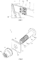
- FIG. 1 is a cross-sectional view of an aircraft fuselage 10 according to an exemplary embodiment.
- FIG. 2 is an exploded view of a coupler 1 shown in FIG. 1 .
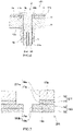
- FIG. 3 is a cross-sectional view showing the coupler 1 of FIG. 2 together with a frame 11 and beam 12 which are coupled by the coupler 1.
- FIG. 4 is a partial front view of the frame 11 shown in FIG. 1 .
- the aircraft fuselage 10 shown in FIG. 1 includes an aircraft component coupling assembly 15.
- the coupling assembly 15 includes at least one coupler 1 (couplers 1 in this embodiment), a frame 11 (first plate structure), and a beam 12 (second plate structure).
- the frame 11 and beam 12 are an example of a pair of aircraft components placed on each other and coupled by the coupler 1.
- the frame 11 is a part of the framework of the aircraft fuselage 10.
- the frame 11 is disposed on the inner circumferential surface of the aircraft fuselage 10 and extends in the circumferential direction to support the skin of the aircraft fuselage 10.
- the frame 11 may be made of metallic or non-metallic material.
- the frame 11 includes a metallic structure to be joined to the beam 12, the structure being located between the top and bottom of the inner circumferential surface of the aircraft fuselage 10 and extending in the left-right direction from the inner circumferential surface of the aircraft fuselage 10.
- This structure may be integral with the frame 11 or may be separate from and coupled to the frame 11.
- this structure will be simply referred to as "frame 11" for convenience of illustration.
- the beam 12 is a floor beam that divides the internal space of the aircraft fuselage 10 into two upper and lower compartments and from which loads are transmitted to the frame 11.
- the beam 12 is located inside the aircraft fuselage 10 and extends in the left-right direction. The direction of the normal to the major surface of the beam 12 coincides with the front-rear direction.
- a longitudinal end of the beam 12 is placed on a part of the frame 11 and coupled to the frame 11.
- the beam 12 is made of, for example, a composite material containing carbon.
- the frame 11 includes a first insertion hole 11a extending through the thickness of the frame 11 and at least one first serration 11b located on an outer surface of the frame 11 and surrounding the first insertion hole 11a, the outer surface facing away from the beam 12.
- the first serration 11b is brought into mesh with a second serration 3a of a contact structure 3 described later.
- the first serrations 11b are located at discrete locations on the outer surface of the frame 11.
- the contour of the first insertion hole 11a is circular in this example, but not limited to being circular.
- the first serration 11b has, for example, a serrated pattern including peaks and valleys extending in a first direction (e.g., the up-down direction) and alternating in a second direction perpendicular to the first direction (e.g., the left-right direction). All the peaks have the same features, and all the valleys have the same features. In this embodiment, the peaks and valleys of each first serration 11b extend straight in the first direction.
- the first direction is the same for all the first serrations 11b of the frame 11, and the second direction is also the same for all the first serrations 11b.
- the serrated pattern of the first serration 11b may include peaks of different shapes or valleys of different shapes.
- the serrated patterns of the first serrations 11b may be different from one another.
- the beam 12 includes second insertion holes 12a extending through the thickness of the beam 12 and having a smaller inner diameter than the first insertion holes 11a.
- the frame 11 and beam 12 are coupled by the couplers 1 located at discrete locations in a plane perpendicular to the front-rear direction and inserted into the first and second insertion holes 11a and 12a.
- the facing surfaces of the frame 11 and beam 12 are flat.
- a cabin is located above the beam 12.
- the beam 12 is beneath a floor assembly defining the bottom of the cabin and supports the floor assembly from below.
- the beam 12 receives loads transmitted from the floor assembly. Since the beam 12 is coupled to the frame 11 by the couplers 1, the loads are transmitted from the beam 12 to the frame 11. Thus, the loads applied to the floor assembly are borne by the aircraft fuselage 10.
- the coupler 1 includes a shaft structure 2, a contact structure 3, and a pressing structure 4.
- the shaft structure 2 has an outer diameter equal to the inner diameters of the second insertion hole 12a and a third insertion hole 3b of the contact structure 3, and is inserted into the first, second, and third insertion holes 11a, 12a, and 3b.
- the shaft structure 2 includes a fixed engagement portion 21b fixedly engageable with the outer surface of one of the frame 11 and contact structure 3.
- the statement that diameters are equal encompasses the case where the diameters differ by a slight amount within tolerance.
- the shaft structure 2 includes a shaft portion 21.
- the shaft portion 21 includes the fixed engagement portion 21b and is inserted into the first, second, and third insertion holes 11a, 12a, and 3b.
- the outline of the radial cross-section of the shaft portion 21 has, for example, the same shape as the contours of the first and second insertion holes 11a and 12a.
- the fixed engagement portion 21b is located at one axial end of the shaft portion 21.
- the fixed engagement portion 21b is located at the end (the beam 12-side end) opposite that part of the shaft portion 21 of the shaft structure 2 which is inserted into and through the first, second, and third insertion holes 11a, 12a, and 3b (this part will be simply referred to as “distal insertion part” hereinafter).
- the contact structure 3 includes a second serration 3a that contacts the outer surface of the frame 11 to mesh with the first serration 11b of the frame 11.
- the contact structure 3 is combined with the shaft portion 21.
- the contact structure 3 is located radially outward of the shaft portion 21 and contacts the outer surface of the frame 11.
- the third insertion hole 3b of the contact structure 3 extends through the thickness of the contact structure 3.
- the contour of the third insertion hole 3b has the same shape as the outline of the radial cross-section of the shaft portion 21.
- the shaft portion 21 is inserted into the third insertion hole 3b.
- the inner diameter of the third insertion hole 3b is smaller than the inner diameter of the first insertion hole 11a.
- the inner diameter of the third insertion hole 3b is equal to the outer diameter of that part of the shaft portion 21 which is surrounded by the inner circumferential surface of the third insertion hole 3b.
- the second serration 3a is placed to mesh with the first serration 11b in a direction from the distal insertion part to the opposite end.
- the contact structure 3 is placed with the second serration 3a facing away from the distal insertion part of the shaft portion 21.
- the pressing structure 4 engages with the shaft structure 2 to press the other of the outer surface of the beam 12 and contact structure 3.
- the pressing structure 4 presses the outer surface of the contact structure 3.
- the pressing structure 4 is attached to the distal insertion part of the shaft portion 21.
- the pressing structure 4 presses the contact structure 3 against the outer surface of the frame 11 at a location between the pressing structure 4 and the fixed engagement portion 21b, thus pressing the frame 11 against the beam 12 via the contact structure 3.
- the inner diameter of the first insertion hole 11a of the frame 11 is larger than the inner diameter of the second insertion hole 12a of the beam 12. This makes it easy to place the frame 11 and beam 12 on each other in such a manner that the second insertion hole 12a is inside the first insertion hole 11a when the frame 11 and beam 12 are viewed in their thickness direction. As such, the first and second insertion holes 11a and 12a can easily be aligned with each other, and the shaft portion 21 can easily be inserted into the first and second insertion holes 11a and 12a.
- the inner diameter of the second insertion hole 12a of the beam 12 is smaller than the inner diameter of the first insertion hole 11a of the frame 11 and, in this example, is equal to the inner diameter of the third insertion hole 3b.
- the radial clearance between the second insertion hole 12a and the shaft portion 21 inserted into the second insertion hole 12a is reduced.
- the adjustment of the relative position between the frame 11 and beam 12 can be performed somewhat roughly.
- the adjustment of the relative position between the shaft portion 21 and contact structure 3 in the radial direction of the third insertion hole 3b and the adjustment of the relative position between the shaft portion 21 and beam 12 in the radial direction of the second insertion hole 12a are accomplished precisely.
- the outer diameter of that part of the shaft portion 21 which is surrounded by the inner circumferential surface of the second insertion hole 12a may be equal to or different from the outer diameter of that part of the shaft portion 21 which is surrounded by the inner circumferential surface of the third insertion hole 3b.
- the shaft portion 21 includes an external thread 21c on its circumferential surface.
- the external thread 21c is located in a part of the shaft portion 21, in particular in a region extending from the distal end of the distal insertion part of the shaft portion 21 to a point located between the distal end of the distal insertion part and the opposite end of the shaft portion 21 in the axial direction of the shaft portion 21.
- the external thread 21c is not limited to this location.
- the distal end of the distal insertion part of the shaft portion 21 includes an insertion hole 21d into which a hexagonal wrench is insertable.
- the pressing structure 4 is, for example, a nut including an internal thread 4a engageable with the external thread 21c.
- the coupler 1 is a fastener including the external and internal threads 21c and 4a.
- the external and internal threads 21c and 4a are engaged to press the second serration 3a against the first serration 11b.
- the shaft structure 2 includes a bolt.
- the bolt includes a head.
- the shaft portion 21 is the shaft of the bolt, and the fixed engagement portion 21b is the head of the bolt.
- the contact structure 3 is a plate fitted around the shaft portion 21.
- the shaft structure 2 and contact structure 3 may be integral with each other.
- the shaft structure 2 may be devoid of the bolt.
- the pressing structure 4 may be engaged with the shaft portion 21 of the shaft structure 2 by means other than thread engagement.
- the operator prepares the frame 11 including the first insertion hole 11a and the beam 12 including the second insertion hole 12a in the aircraft fuselage 10.
- the operator places the frame 11 and beam 12 on each other in the front-rear direction and adjusts the relative position between the frame 11 and beam 12 to align the first and second insertion holes 11a and 12a.
- the operator need not adjust the relative position between the frame 11 and beam 12 so precisely, because the inner diameter of the first insertion holes 11a is different from the inner diameter of the second insertion holes 12a. This reduces the time required for the adjustment of the relative position between the frame 11 and beam 12.
- the inner diameter of the first insertion hole 11a is larger than the inner diameter of the second insertion hole 12a.
- the inner diameter of the first insertion hole 11a may, for example, be smaller than the inner diameter of the second insertion hole 12b from the viewpoint of reducing the time required for the adjustment of the relative position between the frame 11 and beam 12.
- the operator inserts the shaft portion 21 of the shaft structure 2 into the second insertion hole 12a and then into the first insertion hole 11a, thus fixedly engaging the fixed engagement portion 21b of the shaft structure 2 with the outer surface of the beam 12.
- the contact structure 3 is fitted around the shaft portion 21 of the shaft structure 2 in the direction from the distal end to the opposite end of the distal insertion part of the shaft portion 21 (on the frame 11 side in the front-rear direction) to bring the second serration 3a of the contact structure 3 into mesh with the first serration 11b of the frame 11.
- the operator attaches the pressing structure 4 around the shaft portion 21.
- the shaft portion 21 is a shaft of a bolt and the pressing structure 4 is a nut
- the internal thread 4a of the pressing structure 4 is brought into engagement with the external thread 21c of the shaft portion 21.
- the hexagonal wrench is inserted into the insertion hole 21d, and the inserted wrench is used to engage the internal thread 4a of the pressing structure with the external thread 21c of the shaft portion 21 on the frame 11 side in the front-rear direction.
- This thread engagement using the wrench can be efficiently accomplished with the axis of the shaft portion 21 fixed in place.
- the operator brings the external and internal threads 21c and 4a into engagement at all the coupling points in the manner as described above. Consequently, the frame 11 and beam 12 are coupled by the couplers 1 at all the coupling points.
- the frame 11 which includes the first insertion holes 11a extending through the thickness of the frame 11 and the first serrations 11b located on an outer surface of the frame 11 and surrounding the first insertion holes 11a, and the beam 12 which includes the second insertion holes 12a extending through the thickness of the beam 12 and having a smaller inner diameter than the first insertion holes 11a, are placed on each other with the first serrations 11b facing outward, and the frame 11 and beam 12 thus placed are coupled by the couplers 1.
- the coupling assembly 15 with the frame 11 and beam 12 coupled together is constructed.
- each first serration 11b extends in the up-down direction.
- loads are reliably transmitted from the beam 12 to the frame 11 in the left-right direction.
- the meshing of the first and second serrations 11b and 3a allows the frame 11 and contact structure 3 to be in contact over a large area, leading to increased friction resistance in the plane of contact between the frame 11 and contact structure 3. This results in proper load transmission not only in the left-right direction but also in other directions.
- the frame 11 and beam 12 are placed on each other, and the shaft structure 2 is inserted into the first and insertion holes 11a and 12a. Further, the outer surface of the contact structure 3 is pressed by the pressing structure 4 at a location between the pressing structure 4 and the fixed engagement portion 21b, and the second serration 3a of the contact structure 3 pressed by the pressing structure 4 is brought into mesh with the first serration 11b of the frame 11.
- the shaft structure 2 can be quickly inserted into the first and second insertion holes 11a and 12a even in the case where the first and second insertion holes 11a and 12a are not aligned so precisely. Additionally, since the first and insertion holes 11a and 12a can be formed beforehand in the frame 11 and beam 12, the frame 11 and beam 12 need not be subj ected to boring when they are coupled together. This can reduce the time (flow time) and effort required for the coupling process.
- the coupler 1 can be constructed of the shaft structure 2, contact structure 3, and pressing structure 4, the configuration of the coupler 1 can be simplified. This can reduce the cost spent on the coupler 1.
- the relative position between the shaft structure 2 and frame 11 can be adjusted precisely with respect to the axis of the shaft structure 2, and the shaft structure 2 and frame 11 can be in surface contact over a large area.
- the shaft structure 2 has an outer diameter equal to the inner diameters of the second insertion hole 12a of the beam 12 and the third insertion hole 3b of the contact structure 3. Further, the inner diameters of the second insertion hole 12a of the beam 12 and the third insertion hole 3b of the contact structure 3 are smaller than the inner diameter of the first insertion hole 11a of the frame 11. Thus, loads from the beam 12 can be reliably transmitted to the shaft structure 2, contact structure 3, and frame 11.
- the use of the coupler 1 permits proper load transmission from one to the other of the frame 11 and beam 12, leading to the coupling assembly 15 having a high coupling strength.
- first and second plate structures are coupled with the aid of serrations
- at least the respective portions of the first and second plate structures where the serrations are located need to be made of metallic material.
- the beam 12 (second plate structure) need not include any serration. This eliminates the need to use any metal as the material of the beam 12, thus enlarging the range of choices for the material of the beam 12 and increasing the design flexibility of the beam 12.
- the use of the coupler 1 allows the beam 12 made of composite material to be efficiently coupled to the frame 11 without the need for any eccentric bushings.
- the coupling assembly 15 with the frame 11 and beam 12 coupled together can be constructed in a simple configuration and at a low cost.
- the fixed engagement portion 21b is located at the end of the shaft structure 2 opposite the distal insertion part of the shaft structure 2, and the second serration 3a is placed to mesh with the first serration 11b in the direction from the distal insertion part to the opposite end of the shaft structure 2.
- the second serration 3a can easily be pressed against the first serration 11b by the pressing structure 4, and this allows the first and second serrations 11b and 3a to securely mesh with each other.
- the shaft structure 2 includes the shaft portion 21 including the external thread 21c on the circumferential surface of the shaft portion 21, and the pressing structure 4 is a nut including the internal thread 4a engageable with the external thread 21c.
- the external and internal threads 21c and 4a are engaged to press the second serration 3a against the first serration 11b.
- the configuration of the pressing structure 4 can be relatively simple, and the pressing force applied by the pressing structure 4 in the axial direction of the shaft structure 2 can easily be adjusted by varying the degree of thread engagement between the external and internal threads 21c and 4a.
- the shaft structure 2 includes a bolt including a head, the shaft portion 21 is the shaft of the bolt, the fixed engagement portion 21b is the head of the bolt, and the contact structure 3 is a plate fitted around the shaft portion 21.
- the configuration of the coupler 1 can be relatively simple, and the coupler 1 can be constructed quickly at a low cost by combining an existing bolt and plate.
- the facing surfaces of the frame 11 and beam 12 are flat.
- the relative position between the frame 11 and beam 12 need not be adjusted so precisely, unlike the case where, for example, the facing surfaces of the frame 11 and beam 12 are provided with serrations. As such, sufficient adjustment of the relative position between the frame 11 and beam 12 can be accomplished quickly.
- other embodiments will be described with emphasis on differences from the first embodiment.
- FIG. 5 is a partial front view of a frame 111 according to a second embodiment.
- the frame 111 includes first insertion holes 111a and first serrations 111b.
- the first serrations 111b surround the first insertion holes 111a.
- the peaks and valleys extend radially as a whole with respect to the center in the left-right and up-down directions of the region enclosed by the first serrations 111b.
- the above configuration is advantageous in that over the region where the first serrations 111b and the second serrations 3a are in mesh, loads imposed on the beam 12 can be more reliably borne by the frame 111 in diverse directions extending radially from the above center along the major surface of the frame 111.
- FIG. 6 is a cross-sectional view showing a coupler 101 according to a third embodiment together with the frame 11 and beam 12 which are coupled by the coupler 101.
- the coupler 101 includes the shaft structure 2 and pressing structure 4 identical to those of the coupler 1.
- the contact structure 3 is placed with the second serration 3a facing toward the distal insertion part of the shaft portion 21.
- the shaft portion 21 of the shaft structure 2 is inserted into the first insertion hole 11a and then into the second insertion hole 12a.
- the second serration 3a of the contact structure 3 is pressed against the first serration 11b toward the pressing structure 4.
- Such a coupling assembly provides the same benefits as the coupling assemblies of the embodiments previously described.
- FIG. 7 is a partial cross-sectional view showing a coupler 201 and frame 211 according to a fourth embodiment.
- the coupler 201 includes a contact structure 103.
- the contact structure 103 includes a contact plate 18 and a serrated element 19.
- the contact plate 18 includes a through hole 18a extending through the thickness of the contact plate 18.
- the serrated element 19 is placed on and secured to the contact plate 18.
- the serrated element 19 is plate-shaped and includes a through hole 19a extending through the thickness of the serrated element 19 and a second serration 19b.
- the through hole 18a of the contact plate 18 and the through hole 19a of the serrated element 19 form a third insertion hole 103b.
- the frame 211 includes a base plate 16 and a serrated element 17.
- the base plate 16 includes a through hole 16a extending through the thickness of the base plate 16.
- the serrated element 17 is placed on and secured to the base plate 16.
- the serrated element 17 is plate-shaped and includes a through hole 17a extending through the thickness of the serrated element 17 and a first serration 17b.
- the through hole 16a of the base plate 16 and the through hole 17a of the serrated element 17 are aligned to form a first insertion hole 211a.
- the contact structure 103 can be constructed of the contact plate 18 and serrated element 19.
- the contact structure 103 can easily be modified in various ways by using the same contact plate 18 with different serrated elements 19.
- the frame 211 can be constructed of the base plate 16 and the serrated element 17.
- the frame 211 can easily be adapted to different couplers by using the same base plate 16 with different serrated elements 17.
- the securing of the serrated element 19 to the contact plate 18 and the securing of the serrated element 17 to the base plate 16 are accomplished, for example, by adhesive bonding.
- the securing technique is not limited to adhesive bonding, and the securing of the serrated elements 17 and 19 may be accomplished, for example, by using fasteners.
- the coupler 201 may be combined with the frame 11 or 111, and the frame 211 may be combined with the coupler 1 or coupler 101.
- the present disclosure is not limited to the embodiments described above, and changes, additions, or deletions can be made to the configurations of the above embodiments without departing from the gist of the present disclosure.
- the first plate structure coupled in the aircraft component coupling assembly of the present disclosure is not limited to the frames 11 and 111, and the second plate structure coupled in the coupling assembly is not limited to the beam 12.
- the first and second plate structures may be other plate structures disposed in an aircraft.
Landscapes
- Engineering & Computer Science (AREA)
- General Engineering & Computer Science (AREA)
- Mechanical Engineering (AREA)
- Aviation & Aerospace Engineering (AREA)
- Manufacturing & Machinery (AREA)
- Transportation (AREA)
- Connection Of Plates (AREA)
- Bolts, Nuts, And Washers (AREA)
Abstract
Description
- The present disclosure relates to an aircraft component coupling assembly and a coupler for aircraft components.
- In production of an aircraft fuselage, a frame disposed on the inner circumferential surface of the fuselage and extending in the circumferential direction to support the skin of the fuselage may be coupled by a coupler to a floor beam dividing the internal space of the fuselage into two upper and lower compartments. In this case, for example, through holes are formed beforehand in those portions of the frame and beam at which the frame and beam are to be coupled, then the respective through holes of the frame and beam are aligned with each other, and finally the coupler is inserted into the through holes to couple the frame and beam together. For example,
Patent Literature 1 discloses the configuration of such a coupler (fastener assembly). - In general, the alignment between the through holes needs to be accomplished with high precision to ensure a high coupling stability. However, such high precision of the alignment is difficult to achieve in the case where the through holes are formed beforehand. In contrast, for example, in the case of placing the frame and beam on each other and then forming the through holes in the frame and beam, the through holes can be aligned precisely.
- PTL 1:
Japanese Patent No. 5267796 - However, the use of the above configuration involves a boring process performed inside the aircraft fuselage, and this process requires a lot of time and effort. Additionally, for example, in the case of disposing eccentric bushings in the respective through holes of the frame and beam and coupling the frame and beam with the aid of the eccentric bushings, the number of components in the coupling assembly is increased because of the eccentric bushings and components for preventing rotation of the bushings, and this could lead to an increased production cost. Such a problem may arise also when aircraft components are coupled together in production of an aircraft.
- It is therefore an object of the present disclosure to provide a coupling method and a coupler for coupling aircraft components, the method and coupler being adapted to reduce the time and effort required for the coupling process and to be implemented at a low cost.
- An aircraft component coupling assembly according to an aspect of the present disclosure includes: first and second plate structures placed on each other; and a coupler coupling the first and second plate structures, wherein the first plate structure includes a first insertion hole and a first serration located on an outer surface of the first plate structure and surrounding the first insertion hole, the outer surface facing away from the second plate structure, wherein the second plate structure includes a second insertion hole differing in inner diameter from the first insertion hole, and wherein the coupler includes a contact structure including a second serration and a third insertion hole, the second serration contacting the outer surface of the first plate structure and meshing with the first serration of the first plate structure, a shaft structure inserted into the first, second, and third insertion holes, the shaft structure including a fixed engagement portion fixedly engaged with an outer surface of one of the second plate structure and the contact structure, and a pressing structure engaged with the shaft structure and pressing an outer surface of the other of the second plate structure and the contact structure.
- Since the inner diameters of the first and second insertion holes are different, the shaft structure can be quickly inserted into the first and second insertion holes even in the case where the first and second insertion holes are not aligned so precisely. Additionally, since the first and insertion holes can be formed beforehand in the first and second plate structures, the first and second plate structures need not be subjected to boring when they are coupled together. This can reduce the time and effort required for the coupling process.
- Additionally, since the second serration is brought into mesh with the first serration, the relative position between the shaft structure and first plate structure can be adjusted precisely with respect to the axis of the shaft structure, and the shaft structure and first plate structure can be in surface contact over a large area.
- Additionally, since the coupler can be constructed of the shaft structure, contact structure, and pressing structure, the configuration of the coupler can be simplified. This can reduce the cost spent on the coupler.
- A coupler according to an aspect of the present disclosure is a coupler for aircraft components that couples first and second plate structures, the first plate structure including a first insertion hole and a first serration located on an outer surface of the first plate structure and surrounding the first insertion hole, the second plate structure including a second insertion hole having a smaller inner diameter than the first insertion hole, the first and second plate structures being placed on each other with the first serration facing outward, the coupler including: a contact structure including a second serration and a third insertion hole, the second serration being contacted with the outer surface of the first plate structure to mesh with the first serration of the first plate structure; a shaft structure that is inserted into the first, second, and third insertion holes, the shaft structure including a fixed engagement portion that is fixedly engaged with an outer surface of one of the second plate structure and the contact structure; and a pressing structure that is engaged with the shaft structure to press an outer surface of the other of the second plate structure and the contact structure.
- The above aspects of the present disclosure provide a coupling method and a coupler for coupling aircraft components, the method and coupler being adapted to reduce the time and effort required for the coupling process and to be implemented at a low cost.
-
-
FIG. 1 is a perspective view showing an aircraft fuselage according to an exemplary embodiment, in particular a part where a beam and frame are coupled. -
FIG. 2 is an exploded view of a coupler shown inFIG. 1 . -
FIG. 3 is a cross-sectional view showing the coupler ofFIG. 2 together with the frame and beam which are coupled by the coupler. -
FIG. 4 is a partial front view of the frame shown inFIG. 1 . -
FIG. 5 is a partial front view of a frame according to a second embodiment. -
FIG. 6 is a cross-sectional view showing a coupler according to a third embodiment together with a frame and beam which are coupled by the coupler. -
FIG. 7 is a partial cross-sectional view showing a coupler and frame according to a fourth embodiment. - Hereinafter, exemplary embodiments will be described with reference to the drawings. In the following description, the front-rear direction and left-right direction of an aircraft will be simply referred to as "front-rear direction" and "left-right direction", respectively.
-
FIG. 1 is a cross-sectional view of anaircraft fuselage 10 according to an exemplary embodiment.FIG. 2 is an exploded view of acoupler 1 shown inFIG. 1 .FIG. 3 is a cross-sectional view showing thecoupler 1 ofFIG. 2 together with aframe 11 andbeam 12 which are coupled by thecoupler 1.FIG. 4 is a partial front view of theframe 11 shown inFIG. 1 . - The
aircraft fuselage 10 shown inFIG. 1 includes an aircraftcomponent coupling assembly 15. Thecoupling assembly 15 includes at least one coupler 1 (couplers 1 in this embodiment), a frame 11 (first plate structure), and a beam 12 (second plate structure). Theframe 11 andbeam 12 are an example of a pair of aircraft components placed on each other and coupled by thecoupler 1. - The
frame 11 is a part of the framework of theaircraft fuselage 10. Theframe 11 is disposed on the inner circumferential surface of theaircraft fuselage 10 and extends in the circumferential direction to support the skin of theaircraft fuselage 10. Theframe 11 may be made of metallic or non-metallic material. Theframe 11 includes a metallic structure to be joined to thebeam 12, the structure being located between the top and bottom of the inner circumferential surface of theaircraft fuselage 10 and extending in the left-right direction from the inner circumferential surface of theaircraft fuselage 10. This structure may be integral with theframe 11 or may be separate from and coupled to theframe 11. Hereinafter, this structure will be simply referred to as "frame 11" for convenience of illustration. - The
beam 12 is a floor beam that divides the internal space of theaircraft fuselage 10 into two upper and lower compartments and from which loads are transmitted to theframe 11. Thebeam 12 is located inside theaircraft fuselage 10 and extends in the left-right direction. The direction of the normal to the major surface of thebeam 12 coincides with the front-rear direction. A longitudinal end of thebeam 12 is placed on a part of theframe 11 and coupled to theframe 11. Thebeam 12 is made of, for example, a composite material containing carbon. - As shown in
FIGS. 3 and4 , theframe 11 includes afirst insertion hole 11a extending through the thickness of theframe 11 and at least onefirst serration 11b located on an outer surface of theframe 11 and surrounding thefirst insertion hole 11a, the outer surface facing away from thebeam 12. Thefirst serration 11b is brought into mesh with asecond serration 3a of acontact structure 3 described later. In this embodiment, thefirst serrations 11b are located at discrete locations on the outer surface of theframe 11. - The contour of the
first insertion hole 11a is circular in this example, but not limited to being circular. In a plan view of theframe 11, thefirst serration 11b has, for example, a serrated pattern including peaks and valleys extending in a first direction (e.g., the up-down direction) and alternating in a second direction perpendicular to the first direction (e.g., the left-right direction). All the peaks have the same features, and all the valleys have the same features. In this embodiment, the peaks and valleys of eachfirst serration 11b extend straight in the first direction. The first direction is the same for all thefirst serrations 11b of theframe 11, and the second direction is also the same for all thefirst serrations 11b. - The serrated pattern of the
first serration 11b may include peaks of different shapes or valleys of different shapes. The serrated patterns of thefirst serrations 11b may be different from one another. - The
beam 12 includessecond insertion holes 12a extending through the thickness of thebeam 12 and having a smaller inner diameter than thefirst insertion holes 11a. Theframe 11 andbeam 12 are coupled by thecouplers 1 located at discrete locations in a plane perpendicular to the front-rear direction and inserted into the first andsecond insertion holes frame 11 andbeam 12 are flat. - In the
aircraft fuselage 10, a cabin is located above thebeam 12. Thebeam 12 is beneath a floor assembly defining the bottom of the cabin and supports the floor assembly from below. Thebeam 12 receives loads transmitted from the floor assembly. Since thebeam 12 is coupled to theframe 11 by thecouplers 1, the loads are transmitted from thebeam 12 to theframe 11. Thus, the loads applied to the floor assembly are borne by theaircraft fuselage 10. - The following describes the detailed configurations of the
coupler 1,frame 11, andbeam 12. As shown inFIGS. 2 to 4 , thecoupler 1 includes ashaft structure 2, acontact structure 3, and apressing structure 4. Theshaft structure 2 has an outer diameter equal to the inner diameters of thesecond insertion hole 12a and athird insertion hole 3b of thecontact structure 3, and is inserted into the first, second, andthird insertion holes shaft structure 2 includes a fixedengagement portion 21b fixedly engageable with the outer surface of one of theframe 11 andcontact structure 3. As used herein, the statement that diameters are equal encompasses the case where the diameters differ by a slight amount within tolerance. - More specifically, the
shaft structure 2 includes ashaft portion 21. Theshaft portion 21 includes the fixedengagement portion 21b and is inserted into the first, second, andthird insertion holes shaft portion 21 has, for example, the same shape as the contours of the first andsecond insertion holes engagement portion 21b is located at one axial end of theshaft portion 21. In this embodiment, the fixedengagement portion 21b is located at the end (the beam 12-side end) opposite that part of theshaft portion 21 of theshaft structure 2 which is inserted into and through the first, second, andthird insertion holes - The
contact structure 3 includes asecond serration 3a that contacts the outer surface of theframe 11 to mesh with thefirst serration 11b of theframe 11. Thecontact structure 3 is combined with theshaft portion 21. Thecontact structure 3 is located radially outward of theshaft portion 21 and contacts the outer surface of theframe 11. - The
third insertion hole 3b of thecontact structure 3 extends through the thickness of thecontact structure 3. The contour of thethird insertion hole 3b has the same shape as the outline of the radial cross-section of theshaft portion 21. Theshaft portion 21 is inserted into thethird insertion hole 3b. The inner diameter of thethird insertion hole 3b is smaller than the inner diameter of thefirst insertion hole 11a. The inner diameter of thethird insertion hole 3b is equal to the outer diameter of that part of theshaft portion 21 which is surrounded by the inner circumferential surface of thethird insertion hole 3b. Thus, the radial clearance between thethird insertion hole 3b and theshaft portion 21 inserted into thethird insertion hole 3b is reduced. - In this embodiment, the
second serration 3a is placed to mesh with thefirst serration 11b in a direction from the distal insertion part to the opposite end. In other words, thecontact structure 3 is placed with thesecond serration 3a facing away from the distal insertion part of theshaft portion 21. - The
pressing structure 4 engages with theshaft structure 2 to press the other of the outer surface of thebeam 12 andcontact structure 3. In this embodiment, thepressing structure 4 presses the outer surface of thecontact structure 3. Thepressing structure 4 is attached to the distal insertion part of theshaft portion 21. In this embodiment, thepressing structure 4 presses thecontact structure 3 against the outer surface of theframe 11 at a location between thepressing structure 4 and the fixedengagement portion 21b, thus pressing theframe 11 against thebeam 12 via thecontact structure 3. - The inner diameter of the
first insertion hole 11a of theframe 11 is larger than the inner diameter of thesecond insertion hole 12a of thebeam 12. This makes it easy to place theframe 11 andbeam 12 on each other in such a manner that thesecond insertion hole 12a is inside thefirst insertion hole 11a when theframe 11 andbeam 12 are viewed in their thickness direction. As such, the first andsecond insertion holes shaft portion 21 can easily be inserted into the first andsecond insertion holes - The inner diameter of the
second insertion hole 12a of thebeam 12 is smaller than the inner diameter of thefirst insertion hole 11a of theframe 11 and, in this example, is equal to the inner diameter of thethird insertion hole 3b. Thus, the radial clearance between thesecond insertion hole 12a and theshaft portion 21 inserted into thesecond insertion hole 12a is reduced. - As described above, the adjustment of the relative position between the
frame 11 andbeam 12 can be performed somewhat roughly. In contrast, the adjustment of the relative position between theshaft portion 21 andcontact structure 3 in the radial direction of thethird insertion hole 3b and the adjustment of the relative position between theshaft portion 21 andbeam 12 in the radial direction of thesecond insertion hole 12a are accomplished precisely. The outer diameter of that part of theshaft portion 21 which is surrounded by the inner circumferential surface of thesecond insertion hole 12a may be equal to or different from the outer diameter of that part of theshaft portion 21 which is surrounded by the inner circumferential surface of thethird insertion hole 3b. - As shown in
FIGS. 2 and3 , theshaft portion 21 includes anexternal thread 21c on its circumferential surface. Theexternal thread 21c is located in a part of theshaft portion 21, in particular in a region extending from the distal end of the distal insertion part of theshaft portion 21 to a point located between the distal end of the distal insertion part and the opposite end of theshaft portion 21 in the axial direction of theshaft portion 21. However, theexternal thread 21c is not limited to this location. The distal end of the distal insertion part of theshaft portion 21 includes aninsertion hole 21d into which a hexagonal wrench is insertable. Thepressing structure 4 is, for example, a nut including aninternal thread 4a engageable with theexternal thread 21c. That is, in this embodiment, thecoupler 1 is a fastener including the external andinternal threads coupler 1, the external andinternal threads second serration 3a against thefirst serration 11b. - In this embodiment, the
shaft structure 2 includes a bolt. The bolt includes a head. Theshaft portion 21 is the shaft of the bolt, and the fixedengagement portion 21b is the head of the bolt. Thecontact structure 3 is a plate fitted around theshaft portion 21. Theshaft structure 2 andcontact structure 3 may be integral with each other. Theshaft structure 2 may be devoid of the bolt. In this case, thepressing structure 4 may be engaged with theshaft portion 21 of theshaft structure 2 by means other than thread engagement. - The following describes the method of constructing the
coupling assembly 15 in which theframe 11 andbeam 12 are coupled by thecoupler 1. First, the operator prepares theframe 11 including thefirst insertion hole 11a and thebeam 12 including thesecond insertion hole 12a in theaircraft fuselage 10. The operator places theframe 11 andbeam 12 on each other in the front-rear direction and adjusts the relative position between theframe 11 andbeam 12 to align the first andsecond insertion holes frame 11 andbeam 12 so precisely, because the inner diameter of thefirst insertion holes 11a is different from the inner diameter of thesecond insertion holes 12a. This reduces the time required for the adjustment of the relative position between theframe 11 andbeam 12. - In this embodiment, the inner diameter of the
first insertion hole 11a is larger than the inner diameter of thesecond insertion hole 12a. However, the inner diameter of thefirst insertion hole 11a may, for example, be smaller than the inner diameter of the second insertion hole 12b from the viewpoint of reducing the time required for the adjustment of the relative position between theframe 11 andbeam 12. - Next, the operator inserts the
shaft portion 21 of theshaft structure 2 into thesecond insertion hole 12a and then into thefirst insertion hole 11a, thus fixedly engaging the fixedengagement portion 21b of theshaft structure 2 with the outer surface of thebeam 12. After that, thecontact structure 3 is fitted around theshaft portion 21 of theshaft structure 2 in the direction from the distal end to the opposite end of the distal insertion part of the shaft portion 21 (on theframe 11 side in the front-rear direction) to bring thesecond serration 3a of thecontact structure 3 into mesh with thefirst serration 11b of theframe 11. In this state, the operator attaches thepressing structure 4 around theshaft portion 21. In this embodiment, where theshaft portion 21 is a shaft of a bolt and thepressing structure 4 is a nut, theinternal thread 4a of thepressing structure 4 is brought into engagement with theexternal thread 21c of theshaft portion 21. - In this embodiment, where the distal end of the distal insertion part of the
shaft portion 21 includes theinsertion hole 21d for a hexagonal wrench, the hexagonal wrench is inserted into theinsertion hole 21d, and the inserted wrench is used to engage theinternal thread 4a of the pressing structure with theexternal thread 21c of theshaft portion 21 on theframe 11 side in the front-rear direction. This thread engagement using the wrench can be efficiently accomplished with the axis of theshaft portion 21 fixed in place. The operator brings the external andinternal threads frame 11 andbeam 12 are coupled by thecouplers 1 at all the coupling points. - As described above, the
frame 11 which includes thefirst insertion holes 11a extending through the thickness of theframe 11 and thefirst serrations 11b located on an outer surface of theframe 11 and surrounding thefirst insertion holes 11a, and thebeam 12 which includes thesecond insertion holes 12a extending through the thickness of thebeam 12 and having a smaller inner diameter than thefirst insertion holes 11a, are placed on each other with thefirst serrations 11b facing outward, and theframe 11 andbeam 12 thus placed are coupled by thecouplers 1. In this manner, thecoupling assembly 15 with theframe 11 andbeam 12 coupled together is constructed. - In this embodiment, as shown in
FIG. 4 , the peaks and valleys of eachfirst serration 11b extend in the up-down direction. Thus, with the first andsecond serrations beam 12 to theframe 11 in the left-right direction. Additionally, the meshing of the first andsecond serrations frame 11 andcontact structure 3 to be in contact over a large area, leading to increased friction resistance in the plane of contact between theframe 11 andcontact structure 3. This results in proper load transmission not only in the left-right direction but also in other directions. - In this embodiment, as described above, the
frame 11 andbeam 12 are placed on each other, and theshaft structure 2 is inserted into the first andinsertion holes contact structure 3 is pressed by thepressing structure 4 at a location between thepressing structure 4 and the fixedengagement portion 21b, and thesecond serration 3a of thecontact structure 3 pressed by thepressing structure 4 is brought into mesh with thefirst serration 11b of theframe 11. - Since the inner diameters of the first and
second insertion holes shaft structure 2 can be quickly inserted into the first andsecond insertion holes second insertion holes insertion holes frame 11 andbeam 12, theframe 11 andbeam 12 need not be subj ected to boring when they are coupled together. This can reduce the time (flow time) and effort required for the coupling process. - Additionally, since the
coupler 1 can be constructed of theshaft structure 2,contact structure 3, andpressing structure 4, the configuration of thecoupler 1 can be simplified. This can reduce the cost spent on thecoupler 1. - Additionally, since the
second serration 3a is brought into mesh with thefirst serration 11b, the relative position between theshaft structure 2 andframe 11 can be adjusted precisely with respect to the axis of theshaft structure 2, and theshaft structure 2 andframe 11 can be in surface contact over a large area. - Additionally, the
shaft structure 2 has an outer diameter equal to the inner diameters of thesecond insertion hole 12a of thebeam 12 and thethird insertion hole 3b of thecontact structure 3. Further, the inner diameters of thesecond insertion hole 12a of thebeam 12 and thethird insertion hole 3b of thecontact structure 3 are smaller than the inner diameter of thefirst insertion hole 11a of theframe 11. Thus, loads from thebeam 12 can be reliably transmitted to theshaft structure 2,contact structure 3, andframe 11. The use of thecoupler 1 permits proper load transmission from one to the other of theframe 11 andbeam 12, leading to thecoupling assembly 15 having a high coupling strength. - Generally, in the case where first and second plate structures are coupled with the aid of serrations, at least the respective portions of the first and second plate structures where the serrations are located need to be made of metallic material. In contrast, in this embodiment, the beam 12 (second plate structure) need not include any serration. This eliminates the need to use any metal as the material of the
beam 12, thus enlarging the range of choices for the material of thebeam 12 and increasing the design flexibility of thebeam 12. - In the case where a plate structure made of composite material is coupled to another plate structure using an eccentric bushing, the insertion of the eccentric bushing into an insertion hole of the composite material plate structure could cause wearing down of the composite material due to rotation of the eccentric bushing. A possible approach to this problem is to attach a rotation stopper to the insertion hole; however, it is often difficult to equip a plate structure made of composite material with a rotation stopper because of the properties of the plate structure. Additionally, some plate structures made of composite material and provided with insertion holes have relatively low strength around the insertion holes. In such cases, the regions around the insertion holes need to be reinforced considerably. For the above reasons, the portion of a composite material plate structure that is coupled to another plate structure needs to be equipped with, for example, a link made of metallic material. This could lead to complicated configuration and increased cost of the coupling assembly.
- In contrast, in this embodiment, the use of the
coupler 1 allows thebeam 12 made of composite material to be efficiently coupled to theframe 11 without the need for any eccentric bushings. Thus, thecoupling assembly 15 with theframe 11 andbeam 12 coupled together can be constructed in a simple configuration and at a low cost. - Additionally, the fixed
engagement portion 21b is located at the end of theshaft structure 2 opposite the distal insertion part of theshaft structure 2, and thesecond serration 3a is placed to mesh with thefirst serration 11b in the direction from the distal insertion part to the opposite end of theshaft structure 2. Thus, thesecond serration 3a can easily be pressed against thefirst serration 11b by thepressing structure 4, and this allows the first andsecond serrations - Additionally, the
shaft structure 2 includes theshaft portion 21 including theexternal thread 21c on the circumferential surface of theshaft portion 21, and thepressing structure 4 is a nut including theinternal thread 4a engageable with theexternal thread 21c. The external andinternal threads second serration 3a against thefirst serration 11b. - Thus, the configuration of the
pressing structure 4 can be relatively simple, and the pressing force applied by thepressing structure 4 in the axial direction of theshaft structure 2 can easily be adjusted by varying the degree of thread engagement between the external andinternal threads - The
shaft structure 2 includes a bolt including a head, theshaft portion 21 is the shaft of the bolt, the fixedengagement portion 21b is the head of the bolt, and thecontact structure 3 is a plate fitted around theshaft portion 21. Thus, the configuration of thecoupler 1 can be relatively simple, and thecoupler 1 can be constructed quickly at a low cost by combining an existing bolt and plate. - The facing surfaces of the
frame 11 andbeam 12 are flat. Thus, the relative position between theframe 11 andbeam 12 need not be adjusted so precisely, unlike the case where, for example, the facing surfaces of theframe 11 andbeam 12 are provided with serrations. As such, sufficient adjustment of the relative position between theframe 11 andbeam 12 can be accomplished quickly. Hereinafter, other embodiments will be described with emphasis on differences from the first embodiment. -
FIG. 5 is a partial front view of aframe 111 according to a second embodiment. As shown inFIG. 5 , theframe 111 includesfirst insertion holes 111a andfirst serrations 111b. In a plan view of theframe 111, thefirst serrations 111b surround thefirst insertion holes 111a. In eachfirst serration 111b, the peaks and valleys extend radially as a whole with respect to the center in the left-right and up-down directions of the region enclosed by thefirst serrations 111b. - The above configuration is advantageous in that over the region where the
first serrations 111b and thesecond serrations 3a are in mesh, loads imposed on thebeam 12 can be more reliably borne by theframe 111 in diverse directions extending radially from the above center along the major surface of theframe 111. -
FIG. 6 is a cross-sectional view showing acoupler 101 according to a third embodiment together with theframe 11 andbeam 12 which are coupled by thecoupler 101. Thecoupler 101 includes theshaft structure 2 andpressing structure 4 identical to those of thecoupler 1. In thecoupler 101, thecontact structure 3 is placed with thesecond serration 3a facing toward the distal insertion part of theshaft portion 21. Theshaft portion 21 of theshaft structure 2 is inserted into thefirst insertion hole 11a and then into thesecond insertion hole 12a. Thus, thesecond serration 3a of thecontact structure 3 is pressed against thefirst serration 11b toward thepressing structure 4. Such a coupling assembly provides the same benefits as the coupling assemblies of the embodiments previously described. -
FIG. 7 is a partial cross-sectional view showing acoupler 201 andframe 211 according to a fourth embodiment. As shown inFIG. 7 , thecoupler 201 includes acontact structure 103. and thecontact structure 103 includes acontact plate 18 and aserrated element 19. Thecontact plate 18 includes a throughhole 18a extending through the thickness of thecontact plate 18. Theserrated element 19 is placed on and secured to thecontact plate 18. Theserrated element 19 is plate-shaped and includes a throughhole 19a extending through the thickness of theserrated element 19 and asecond serration 19b. In the present embodiment, the throughhole 18a of thecontact plate 18 and the throughhole 19a of theserrated element 19 form athird insertion hole 103b. - As shown in
FIG. 7 , theframe 211 includes abase plate 16 and aserrated element 17. Thebase plate 16 includes a throughhole 16a extending through the thickness of thebase plate 16. Theserrated element 17 is placed on and secured to thebase plate 16. Theserrated element 17 is plate-shaped and includes a throughhole 17a extending through the thickness of theserrated element 17 and afirst serration 17b. In the present embodiment, the throughhole 16a of thebase plate 16 and the throughhole 17a of theserrated element 17 are aligned to form afirst insertion hole 211a. - In the above configuration, the
contact structure 103 can be constructed of thecontact plate 18 andserrated element 19. Thus, for example, thecontact structure 103 can easily be modified in various ways by using thesame contact plate 18 with differentserrated elements 19. - Additionally, in the above configuration, the
frame 211 can be constructed of thebase plate 16 and theserrated element 17. Thus, for example, theframe 211 can easily be adapted to different couplers by using thesame base plate 16 with differentserrated elements 17. - The securing of the
serrated element 19 to thecontact plate 18 and the securing of theserrated element 17 to thebase plate 16 are accomplished, for example, by adhesive bonding. The securing technique is not limited to adhesive bonding, and the securing of theserrated elements coupler 201 may be combined with theframe frame 211 may be combined with thecoupler 1 orcoupler 101. - The present disclosure is not limited to the embodiments described above, and changes, additions, or deletions can be made to the configurations of the above embodiments without departing from the gist of the present disclosure. The first plate structure coupled in the aircraft component coupling assembly of the present disclosure is not limited to the
frames beam 12. The first and second plate structures may be other plate structures disposed in an aircraft. -
- 1, 101,201 coupler for aircraft components
- 2 shaft structure
- 3, 103 contact structure
- 3a, 19b second serration
- 3b, 103b third insertion hole
- 4 pressing structure
- 4a internal thread
- 11, 111, 211 frame (first plate structure)
- 11a, 111a, 211a first insertion hole
- 11b, 17b, 111b first serration
- 12 beam (second plate structure)
- 12a second insertion hole
- 15 aircraft component coupling assembly
- 17 serrated element
- 19 serrated element
- 21 shaft portion
- 21b fixed engagement portion
- 21c external thread
Claims (11)
- A coupling assembly comprising:first and second plate structures placed on each other; anda coupler coupling the first and second plate structures,wherein the first plate structure includes a first insertion hole and a first serration located on an outer surface of the first plate structure and surrounding the first insertion hole, the outer surface facing away from the second plate structure,wherein the second plate structure includes a second insertion hole differing in inner diameter from the first insertion hole, andwherein the coupler includesa contact structure including a second serration and a third insertion hole. the second serration contacting the outer surface of the first plate structure and meshing with the first serration of the first plate structure,a shaft structure inserted into the first, second, and third insertion holes, the shaft structure including a fixed engagement portion fixedly engaged with an outer surface of one of the second plate structure and the contact structure, anda pressing structure engaged with the shaft structure and pressing an outer surface of the other of the second plate structure and the contact structure.
- The coupling assembly according to claim 1,wherein the shaft structure has an outer diameter equal to inner diameters of the second insertion hole of the second plate structure and the third insertion hole of the contact structure, andwherein the inner diameters of the second and third insertion holes are smaller than an inner diameter of the first insertion hole.
- The coupling assembly according to claim 1 or 2,wherein the fixed engagement portion is located at an end of the shaft structure opposite a distal insertion part of the shaft structure, the distal insertion part being inserted into and through the first, second, and third insertion holes, andwherein the second serration is placed to mesh with the first serration in a direction from the distal insertion part to the opposite end of the shaft structure.
- The coupling assembly according to any one of claims 1 to 3,wherein the shaft structure includes a shaft portion including an external thread on a circumferential surface of the shaft portion,wherein the pressing structure is a nut including an internal thread engageable with the external thread, andthe external and internal threads are engaged to press the second serration against the first serration.
- The coupling assembly according to claim 4,wherein the shaft structure includes a bolt including a head,wherein the shaft portion is a shaft of the bolt,wherein the fixed engagement portion is the head of the bolt, andwherein the contact structure is a plate fitted around the shaft of the bolt.
- The coupling assembly according to any one of claims 1 to 5, wherein facing surfaces of the first and second plate structures are flat.
- The coupling assembly according to any one of claims 1 to 6, wherein the contact structure includes the third insertion hole, a contact plate, and a coupler serrated element placed on and secured to the contact plate, the coupler serrated element including the second serration.
- The coupling assembly according to any one of claims 1 to 7, wherein the first plate structure includes the first insertion hole, a base plate, and a plate serrated element placed on and secured to the base plate, the plate serrated element including the first serration.
- A coupler for aircraft components that couples first and second plate structures, the first plate structure including a first insertion hole and a first serration located on an outer surface of the first plate structure and surrounding the first insertion hole, the second plate structure including a second insertion hole having a smaller inner diameter than the first insertion hole, the first and second plate structures being placed on each other with the first serration facing outward, the coupler comprising:a contact structure including a second serration and a third insertion hole, the second serration being contacted with the outer surface of the first plate structure to mesh with the first serration of the first plate structure;a shaft structure that is inserted into the first, second, and third insertion holes, the shaft structure including a fixed engagement portion that is fixedly engaged with an outer surface of one of the second plate structure and the contact structure; anda pressing structure that is engaged with the shaft structure to press an outer surface of the other of the second plate structure and the contact structure.
- The coupler according to claim 9, wherein the shaft structure has an outer diameter equal to inner diameters of the second insertion hole of the second plate structure and the third insertion hole of the contact structure.
- The coupler according to claim 10, wherein the contact structure includes the third insertion hole, a contact plate, and a coupler serrated element placed on and secured to the contact plate, the coupler serrated element including the second serration.
Applications Claiming Priority (2)
| Application Number | Priority Date | Filing Date | Title |
|---|---|---|---|
| JP2019096716 | 2019-05-23 | ||
| PCT/JP2020/019951 WO2020235595A1 (en) | 2019-05-23 | 2020-05-20 | Aircraft member joining structure, and joining tool for aircraft members |
Publications (3)
| Publication Number | Publication Date |
|---|---|
| EP3974668A1 true EP3974668A1 (en) | 2022-03-30 |
| EP3974668A4 EP3974668A4 (en) | 2023-06-28 |
| EP3974668B1 EP3974668B1 (en) | 2024-07-03 |
Family
ID=73459384
Family Applications (1)
| Application Number | Title | Priority Date | Filing Date |
|---|---|---|---|
| EP20808927.6A Active EP3974668B1 (en) | 2019-05-23 | 2020-05-20 | Aircraft member joining structure, and joining tool for aircraft members |
Country Status (4)
| Country | Link |
|---|---|
| US (1) | US12305690B2 (en) |
| EP (1) | EP3974668B1 (en) |
| JP (1) | JP7165197B2 (en) |
| WO (1) | WO2020235595A1 (en) |
Families Citing this family (2)
| Publication number | Priority date | Publication date | Assignee | Title |
|---|---|---|---|---|
| CN112550659A (en) * | 2020-12-17 | 2021-03-26 | 中航沈飞民用飞机有限责任公司 | Adjustable erection joint of back fuselage front and back section interface of civil airliner |
| US12286998B1 (en) * | 2023-10-06 | 2025-04-29 | The Boeing Company | Serrated fitting |
Family Cites Families (23)
| Publication number | Priority date | Publication date | Assignee | Title |
|---|---|---|---|---|
| US1346325A (en) * | 1917-10-29 | 1920-07-13 | Willys Overland Co | Hood-hinge support |
| US2846250A (en) * | 1956-08-21 | 1958-08-05 | Orenda Engines Ltd | Fastening and adjustment of rear frame struts |
| JPS5066647A (en) * | 1973-10-20 | 1975-06-05 | ||
| GB8415410D0 (en) * | 1984-06-16 | 1984-07-18 | Orr J | Fastenings |
| GB8611997D0 (en) * | 1986-05-16 | 1986-06-25 | Dowdeswell C V R | Teversible point mounting |
| GB2312265B (en) * | 1996-04-19 | 2000-03-22 | Hadley Ind Plc | Structural assembly |
| US5746558A (en) * | 1996-07-24 | 1998-05-05 | Lockheed Martin Corporation | Locking apparatus for fastening system |
| US5746561A (en) * | 1996-07-24 | 1998-05-05 | Lockheed Martin Corporation | Alignment tolerant fastening system |
| US5888012A (en) * | 1996-07-24 | 1999-03-30 | Lockheed Martin Corporation | Large shear tolerant fastening system |
| JP2002122123A (en) * | 2000-10-13 | 2002-04-26 | Kai Kenchiku Sekkei Jimusho:Kk | Washer |
| JP2002242922A (en) * | 2001-02-19 | 2002-08-28 | Makkusu:Kk | Washer, and screw fastener using the same washer |
| GB0525689D0 (en) | 2005-12-16 | 2006-01-25 | Airbus Uk Ltd | A fastener assembly |
| WO2011063445A1 (en) * | 2009-11-25 | 2011-06-03 | John Thomas Burke | Washer assembly and arcuate threaded fastener |
| DE102010038067B4 (en) * | 2010-10-08 | 2014-07-17 | Wolfgang Weiss | Positive connection with compensation of position errors |
| US20140020321A1 (en) * | 2011-01-18 | 2014-01-23 | Fleet Engineers, Inc. | Precast concrete slab connector |
| DE102012021566B3 (en) * | 2012-06-01 | 2013-08-08 | Bernhard Hahner | centering |
| US9068347B2 (en) * | 2012-12-07 | 2015-06-30 | Illinois Tool Works Inc. | Curtain wall panel bracket leveling system |
| JP2015010686A (en) * | 2013-07-01 | 2015-01-19 | 日立建機株式会社 | Bolt fastening structure |
| JP7025835B2 (en) * | 2016-06-03 | 2022-02-25 | 日産自動車株式会社 | Bolt fastening method |
| US10179640B2 (en) * | 2016-08-24 | 2019-01-15 | The Boeing Company | Wing and method of manufacturing |
| FR3089202B1 (en) * | 2018-11-30 | 2022-05-27 | Airbus Operations Sas | Connecting piece capable of being connected to a support element of an aircraft |
| US11312482B2 (en) * | 2019-06-22 | 2022-04-26 | Textron Innovations Inc. | Component alignment systems for aircraft |
| IT202200000965A1 (en) | 2022-01-20 | 2023-07-20 | Newronika S P A | Device for adaptive treatment of neurological diseases and method of control of a device for adaptive treatment of neurological diseases |
-
2020
- 2020-05-20 WO PCT/JP2020/019951 patent/WO2020235595A1/en not_active Ceased
- 2020-05-20 EP EP20808927.6A patent/EP3974668B1/en active Active
- 2020-05-20 JP JP2020542033A patent/JP7165197B2/en active Active
-
2021
- 2021-11-22 US US17/531,808 patent/US12305690B2/en active Active
Also Published As
| Publication number | Publication date |
|---|---|
| US12305690B2 (en) | 2025-05-20 |
| WO2020235595A1 (en) | 2020-11-26 |
| US20220074446A1 (en) | 2022-03-10 |
| JP7165197B2 (en) | 2022-11-02 |
| JPWO2020235595A1 (en) | 2021-06-10 |
| EP3974668A4 (en) | 2023-06-28 |
| EP3974668B1 (en) | 2024-07-03 |
Similar Documents
| Publication | Publication Date | Title |
|---|---|---|
| US8668181B2 (en) | Device for attaching a piece of furniture to the floor of an aircraft | |
| US12305690B2 (en) | Aircraft component coupling assembly and coupler for aircraft components | |
| US8353659B2 (en) | Fastening method for a fastening bolt of a sub frame to car body and a sub frame rigid collar for car used for the fastening method | |
| CN108657274B (en) | Power steering assembly mount with tapered protrusions | |
| EP2971807B1 (en) | Systems and methods for improving bolted joints | |
| EP3536988A1 (en) | An assembly and method for attaching two components | |
| KR102770089B1 (en) | Self-locking fastener | |
| US9487285B2 (en) | Aircraft fuselage structure | |
| CN105051381B (en) | For improving bolted system and method | |
| US9186867B2 (en) | Assembly including a reinforced composite part with a pre-formed rivet receiving button | |
| EP3303809B1 (en) | Apparatus and method of use of apparatus for locating components of a system | |
| US20240318679A1 (en) | Fastener, fastening assembly and method of installing a fastener | |
| US10081401B2 (en) | Crawler track shoe core metal, resilient crawler track shoe, and crawler track shoe core metal manufacturing method | |
| EP3643600B1 (en) | Bulkhead joint assembly | |
| US11181135B2 (en) | Composite material assembly | |
| KR102732804B1 (en) | The method of riveting a first member and a second member and a combination of the first member and the second member manufactured thereby | |
| EP4158206B1 (en) | A fastening element and a vehicle arrangement | |
| US11745250B2 (en) | Swaging device and swaging method | |
| US20180266462A1 (en) | Connection arrangement, vehicle seat, method for producing a connection arrangement, and method for connecting two components | |
| KR20200137185A (en) | Manufacturing system of vehicle bracket using composite mold | |
| JP2020025963A (en) | Machine element | |
| GB2560761A (en) | Assembly |
Legal Events
| Date | Code | Title | Description |
|---|---|---|---|
| STAA | Information on the status of an ep patent application or granted ep patent |
Free format text: STATUS: THE INTERNATIONAL PUBLICATION HAS BEEN MADE |
|
| PUAI | Public reference made under article 153(3) epc to a published international application that has entered the european phase |
Free format text: ORIGINAL CODE: 0009012 |
|
| STAA | Information on the status of an ep patent application or granted ep patent |
Free format text: STATUS: REQUEST FOR EXAMINATION WAS MADE |
|
| 17P | Request for examination filed |
Effective date: 20210929 |
|
| AK | Designated contracting states |
Kind code of ref document: A1 Designated state(s): AL AT BE BG CH CY CZ DE DK EE ES FI FR GB GR HR HU IE IS IT LI LT LU LV MC MK MT NL NO PL PT RO RS SE SI SK SM TR |
|
| DAV | Request for validation of the european patent (deleted) | ||
| DAX | Request for extension of the european patent (deleted) | ||
| A4 | Supplementary search report drawn up and despatched |
Effective date: 20230530 |
|
| RIC1 | Information provided on ipc code assigned before grant |
Ipc: B64C 1/00 20060101ALI20230523BHEP Ipc: B64F 5/10 20170101ALI20230523BHEP Ipc: F16B 5/02 20060101ALI20230523BHEP Ipc: F16B 43/00 20060101AFI20230523BHEP |
|
| STAA | Information on the status of an ep patent application or granted ep patent |
Free format text: STATUS: EXAMINATION IS IN PROGRESS |
|
| 17Q | First examination report despatched |
Effective date: 20231121 |
|
| GRAP | Despatch of communication of intention to grant a patent |
Free format text: ORIGINAL CODE: EPIDOSNIGR1 |
|
| STAA | Information on the status of an ep patent application or granted ep patent |
Free format text: STATUS: GRANT OF PATENT IS INTENDED |
|
| INTG | Intention to grant announced |
Effective date: 20240307 |
|
| GRAS | Grant fee paid |
Free format text: ORIGINAL CODE: EPIDOSNIGR3 |
|
| GRAA | (expected) grant |
Free format text: ORIGINAL CODE: 0009210 |
|
| STAA | Information on the status of an ep patent application or granted ep patent |
Free format text: STATUS: THE PATENT HAS BEEN GRANTED |
|
| AK | Designated contracting states |
Kind code of ref document: B1 Designated state(s): AL AT BE BG CH CY CZ DE DK EE ES FI FR GB GR HR HU IE IS IT LI LT LU LV MC MK MT NL NO PL PT RO RS SE SI SK SM TR |
|
| REG | Reference to a national code |
Ref country code: CH Ref legal event code: EP |
|
| REG | Reference to a national code |
Ref country code: DE Ref legal event code: R096 Ref document number: 602020033464 Country of ref document: DE |
|
| REG | Reference to a national code |
Ref country code: LT Ref legal event code: MG9D |
|
| REG | Reference to a national code |
Ref country code: NL Ref legal event code: MP Effective date: 20240703 |
|
| PG25 | Lapsed in a contracting state [announced via postgrant information from national office to epo] |
Ref country code: PT Free format text: LAPSE BECAUSE OF FAILURE TO SUBMIT A TRANSLATION OF THE DESCRIPTION OR TO PAY THE FEE WITHIN THE PRESCRIBED TIME-LIMIT Effective date: 20241104 |
|
| REG | Reference to a national code |
Ref country code: AT Ref legal event code: MK05 Ref document number: 1700091 Country of ref document: AT Kind code of ref document: T Effective date: 20240703 |
|
| PG25 | Lapsed in a contracting state [announced via postgrant information from national office to epo] |
Ref country code: NL Free format text: LAPSE BECAUSE OF FAILURE TO SUBMIT A TRANSLATION OF THE DESCRIPTION OR TO PAY THE FEE WITHIN THE PRESCRIBED TIME-LIMIT Effective date: 20240703 |
|
| PG25 | Lapsed in a contracting state [announced via postgrant information from national office to epo] |
Ref country code: PT Free format text: LAPSE BECAUSE OF FAILURE TO SUBMIT A TRANSLATION OF THE DESCRIPTION OR TO PAY THE FEE WITHIN THE PRESCRIBED TIME-LIMIT Effective date: 20241104 Ref country code: NL Free format text: LAPSE BECAUSE OF FAILURE TO SUBMIT A TRANSLATION OF THE DESCRIPTION OR TO PAY THE FEE WITHIN THE PRESCRIBED TIME-LIMIT Effective date: 20240703 |
|
| PG25 | Lapsed in a contracting state [announced via postgrant information from national office to epo] |
Ref country code: NO Free format text: LAPSE BECAUSE OF FAILURE TO SUBMIT A TRANSLATION OF THE DESCRIPTION OR TO PAY THE FEE WITHIN THE PRESCRIBED TIME-LIMIT Effective date: 20241003 |
|
| PG25 | Lapsed in a contracting state [announced via postgrant information from national office to epo] |
Ref country code: GR Free format text: LAPSE BECAUSE OF FAILURE TO SUBMIT A TRANSLATION OF THE DESCRIPTION OR TO PAY THE FEE WITHIN THE PRESCRIBED TIME-LIMIT Effective date: 20241004 Ref country code: PL Free format text: LAPSE BECAUSE OF FAILURE TO SUBMIT A TRANSLATION OF THE DESCRIPTION OR TO PAY THE FEE WITHIN THE PRESCRIBED TIME-LIMIT Effective date: 20240703 Ref country code: FI Free format text: LAPSE BECAUSE OF FAILURE TO SUBMIT A TRANSLATION OF THE DESCRIPTION OR TO PAY THE FEE WITHIN THE PRESCRIBED TIME-LIMIT Effective date: 20240703 |
|
| PG25 | Lapsed in a contracting state [announced via postgrant information from national office to epo] |
Ref country code: BG Free format text: LAPSE BECAUSE OF FAILURE TO SUBMIT A TRANSLATION OF THE DESCRIPTION OR TO PAY THE FEE WITHIN THE PRESCRIBED TIME-LIMIT Effective date: 20240703 |
|
| PG25 | Lapsed in a contracting state [announced via postgrant information from national office to epo] |
Ref country code: LV Free format text: LAPSE BECAUSE OF FAILURE TO SUBMIT A TRANSLATION OF THE DESCRIPTION OR TO PAY THE FEE WITHIN THE PRESCRIBED TIME-LIMIT Effective date: 20240703 |
|
| PG25 | Lapsed in a contracting state [announced via postgrant information from national office to epo] |
Ref country code: AT Free format text: LAPSE BECAUSE OF FAILURE TO SUBMIT A TRANSLATION OF THE DESCRIPTION OR TO PAY THE FEE WITHIN THE PRESCRIBED TIME-LIMIT Effective date: 20240703 Ref country code: IS Free format text: LAPSE BECAUSE OF FAILURE TO SUBMIT A TRANSLATION OF THE DESCRIPTION OR TO PAY THE FEE WITHIN THE PRESCRIBED TIME-LIMIT Effective date: 20241103 |
|
| PG25 | Lapsed in a contracting state [announced via postgrant information from national office to epo] |
Ref country code: CZ Free format text: LAPSE BECAUSE OF FAILURE TO SUBMIT A TRANSLATION OF THE DESCRIPTION OR TO PAY THE FEE WITHIN THE PRESCRIBED TIME-LIMIT Effective date: 20240703 Ref country code: HR Free format text: LAPSE BECAUSE OF FAILURE TO SUBMIT A TRANSLATION OF THE DESCRIPTION OR TO PAY THE FEE WITHIN THE PRESCRIBED TIME-LIMIT Effective date: 20240703 |
|
| PG25 | Lapsed in a contracting state [announced via postgrant information from national office to epo] |
Ref country code: ES Free format text: LAPSE BECAUSE OF FAILURE TO SUBMIT A TRANSLATION OF THE DESCRIPTION OR TO PAY THE FEE WITHIN THE PRESCRIBED TIME-LIMIT Effective date: 20240703 Ref country code: RS Free format text: LAPSE BECAUSE OF FAILURE TO SUBMIT A TRANSLATION OF THE DESCRIPTION OR TO PAY THE FEE WITHIN THE PRESCRIBED TIME-LIMIT Effective date: 20241003 |
|
| PG25 | Lapsed in a contracting state [announced via postgrant information from national office to epo] |
Ref country code: RS Free format text: LAPSE BECAUSE OF FAILURE TO SUBMIT A TRANSLATION OF THE DESCRIPTION OR TO PAY THE FEE WITHIN THE PRESCRIBED TIME-LIMIT Effective date: 20241003 Ref country code: PL Free format text: LAPSE BECAUSE OF FAILURE TO SUBMIT A TRANSLATION OF THE DESCRIPTION OR TO PAY THE FEE WITHIN THE PRESCRIBED TIME-LIMIT Effective date: 20240703 Ref country code: NO Free format text: LAPSE BECAUSE OF FAILURE TO SUBMIT A TRANSLATION OF THE DESCRIPTION OR TO PAY THE FEE WITHIN THE PRESCRIBED TIME-LIMIT Effective date: 20241003 Ref country code: LV Free format text: LAPSE BECAUSE OF FAILURE TO SUBMIT A TRANSLATION OF THE DESCRIPTION OR TO PAY THE FEE WITHIN THE PRESCRIBED TIME-LIMIT Effective date: 20240703 Ref country code: IS Free format text: LAPSE BECAUSE OF FAILURE TO SUBMIT A TRANSLATION OF THE DESCRIPTION OR TO PAY THE FEE WITHIN THE PRESCRIBED TIME-LIMIT Effective date: 20241103 Ref country code: HR Free format text: LAPSE BECAUSE OF FAILURE TO SUBMIT A TRANSLATION OF THE DESCRIPTION OR TO PAY THE FEE WITHIN THE PRESCRIBED TIME-LIMIT Effective date: 20240703 Ref country code: GR Free format text: LAPSE BECAUSE OF FAILURE TO SUBMIT A TRANSLATION OF THE DESCRIPTION OR TO PAY THE FEE WITHIN THE PRESCRIBED TIME-LIMIT Effective date: 20241004 Ref country code: FI Free format text: LAPSE BECAUSE OF FAILURE TO SUBMIT A TRANSLATION OF THE DESCRIPTION OR TO PAY THE FEE WITHIN THE PRESCRIBED TIME-LIMIT Effective date: 20240703 Ref country code: ES Free format text: LAPSE BECAUSE OF FAILURE TO SUBMIT A TRANSLATION OF THE DESCRIPTION OR TO PAY THE FEE WITHIN THE PRESCRIBED TIME-LIMIT Effective date: 20240703 Ref country code: CZ Free format text: LAPSE BECAUSE OF FAILURE TO SUBMIT A TRANSLATION OF THE DESCRIPTION OR TO PAY THE FEE WITHIN THE PRESCRIBED TIME-LIMIT Effective date: 20240703 Ref country code: BG Free format text: LAPSE BECAUSE OF FAILURE TO SUBMIT A TRANSLATION OF THE DESCRIPTION OR TO PAY THE FEE WITHIN THE PRESCRIBED TIME-LIMIT Effective date: 20240703 Ref country code: AT Free format text: LAPSE BECAUSE OF FAILURE TO SUBMIT A TRANSLATION OF THE DESCRIPTION OR TO PAY THE FEE WITHIN THE PRESCRIBED TIME-LIMIT Effective date: 20240703 |
|
| REG | Reference to a national code |
Ref country code: DE Ref legal event code: R097 Ref document number: 602020033464 Country of ref document: DE |
|
| PG25 | Lapsed in a contracting state [announced via postgrant information from national office to epo] |
Ref country code: SM Free format text: LAPSE BECAUSE OF FAILURE TO SUBMIT A TRANSLATION OF THE DESCRIPTION OR TO PAY THE FEE WITHIN THE PRESCRIBED TIME-LIMIT Effective date: 20240703 Ref country code: DK Free format text: LAPSE BECAUSE OF FAILURE TO SUBMIT A TRANSLATION OF THE DESCRIPTION OR TO PAY THE FEE WITHIN THE PRESCRIBED TIME-LIMIT Effective date: 20240703 Ref country code: RO Free format text: LAPSE BECAUSE OF FAILURE TO SUBMIT A TRANSLATION OF THE DESCRIPTION OR TO PAY THE FEE WITHIN THE PRESCRIBED TIME-LIMIT Effective date: 20240703 |
|
| PG25 | Lapsed in a contracting state [announced via postgrant information from national office to epo] |
Ref country code: EE Free format text: LAPSE BECAUSE OF FAILURE TO SUBMIT A TRANSLATION OF THE DESCRIPTION OR TO PAY THE FEE WITHIN THE PRESCRIBED TIME-LIMIT Effective date: 20240703 |
|
| PG25 | Lapsed in a contracting state [announced via postgrant information from national office to epo] |
Ref country code: IT Free format text: LAPSE BECAUSE OF FAILURE TO SUBMIT A TRANSLATION OF THE DESCRIPTION OR TO PAY THE FEE WITHIN THE PRESCRIBED TIME-LIMIT Effective date: 20240703 Ref country code: SK Free format text: LAPSE BECAUSE OF FAILURE TO SUBMIT A TRANSLATION OF THE DESCRIPTION OR TO PAY THE FEE WITHIN THE PRESCRIBED TIME-LIMIT Effective date: 20240703 |
|
| PLBE | No opposition filed within time limit |
Free format text: ORIGINAL CODE: 0009261 |
|
| STAA | Information on the status of an ep patent application or granted ep patent |
Free format text: STATUS: NO OPPOSITION FILED WITHIN TIME LIMIT |
|
| 26N | No opposition filed |
Effective date: 20250404 |
|
| PGFP | Annual fee paid to national office [announced via postgrant information from national office to epo] |
Ref country code: DE Payment date: 20250402 Year of fee payment: 6 |
|
| PGFP | Annual fee paid to national office [announced via postgrant information from national office to epo] |
Ref country code: FR Payment date: 20250401 Year of fee payment: 6 |
|
| PG25 | Lapsed in a contracting state [announced via postgrant information from national office to epo] |
Ref country code: SE Free format text: LAPSE BECAUSE OF FAILURE TO SUBMIT A TRANSLATION OF THE DESCRIPTION OR TO PAY THE FEE WITHIN THE PRESCRIBED TIME-LIMIT Effective date: 20240703 |
|
| REG | Reference to a national code |
Ref country code: CH Ref legal event code: H13 Free format text: ST27 STATUS EVENT CODE: U-0-0-H10-H13 (AS PROVIDED BY THE NATIONAL OFFICE) Effective date: 20251223 |
|
| PG25 | Lapsed in a contracting state [announced via postgrant information from national office to epo] |
Ref country code: LU Free format text: LAPSE BECAUSE OF NON-PAYMENT OF DUE FEES Effective date: 20250520 |
|
| PG25 | Lapsed in a contracting state [announced via postgrant information from national office to epo] |
Ref country code: CH Free format text: LAPSE BECAUSE OF NON-PAYMENT OF DUE FEES Effective date: 20250531 |
|
| GBPC | Gb: european patent ceased through non-payment of renewal fee |
Effective date: 20250520 |
|
| REG | Reference to a national code |
Ref country code: BE Ref legal event code: MM Effective date: 20250531 |
|
| PG25 | Lapsed in a contracting state [announced via postgrant information from national office to epo] |
Ref country code: MC Free format text: LAPSE BECAUSE OF FAILURE TO SUBMIT A TRANSLATION OF THE DESCRIPTION OR TO PAY THE FEE WITHIN THE PRESCRIBED TIME-LIMIT Effective date: 20240703 |
|
| PG25 | Lapsed in a contracting state [announced via postgrant information from national office to epo] |
Ref country code: GB Free format text: LAPSE BECAUSE OF NON-PAYMENT OF DUE FEES Effective date: 20250520 |
|
| PG25 | Lapsed in a contracting state [announced via postgrant information from national office to epo] |
Ref country code: IE Free format text: LAPSE BECAUSE OF NON-PAYMENT OF DUE FEES Effective date: 20250520 |
|
| PG25 | Lapsed in a contracting state [announced via postgrant information from national office to epo] |
Ref country code: BE Free format text: LAPSE BECAUSE OF NON-PAYMENT OF DUE FEES Effective date: 20250531 |