EP3974615A1 - Auger bit - Google Patents
Auger bit Download PDFInfo
- Publication number
- EP3974615A1 EP3974615A1 EP20808910.2A EP20808910A EP3974615A1 EP 3974615 A1 EP3974615 A1 EP 3974615A1 EP 20808910 A EP20808910 A EP 20808910A EP 3974615 A1 EP3974615 A1 EP 3974615A1
- Authority
- EP
- European Patent Office
- Prior art keywords
- tilted
- auger
- head
- axial direction
- parts
- Prior art date
- Legal status (The legal status is an assumption and is not a legal conclusion. Google has not performed a legal analysis and makes no representation as to the accuracy of the status listed.)
- Pending
Links
- 230000007423 decrease Effects 0.000 claims description 4
- 238000009412 basement excavation Methods 0.000 abstract description 51
- 239000000463 material Substances 0.000 description 62
- 238000010586 diagram Methods 0.000 description 14
- 238000005299 abrasion Methods 0.000 description 13
- 229910000831 Steel Inorganic materials 0.000 description 8
- 239000010959 steel Substances 0.000 description 8
- VYZAMTAEIAYCRO-UHFFFAOYSA-N Chromium Chemical compound [Cr] VYZAMTAEIAYCRO-UHFFFAOYSA-N 0.000 description 6
- 101001131990 Homo sapiens Peroxidasin homolog Proteins 0.000 description 6
- ZOKXTWBITQBERF-UHFFFAOYSA-N Molybdenum Chemical compound [Mo] ZOKXTWBITQBERF-UHFFFAOYSA-N 0.000 description 6
- 102100034601 Peroxidasin homolog Human genes 0.000 description 6
- 229910052804 chromium Inorganic materials 0.000 description 6
- 239000011651 chromium Substances 0.000 description 6
- 229910052750 molybdenum Inorganic materials 0.000 description 6
- 239000011733 molybdenum Substances 0.000 description 6
- 239000002689 soil Substances 0.000 description 6
- 238000000034 method Methods 0.000 description 4
- 230000008878 coupling Effects 0.000 description 3
- 238000010168 coupling process Methods 0.000 description 3
- 238000005859 coupling reaction Methods 0.000 description 3
- 230000000694 effects Effects 0.000 description 2
- 239000000956 alloy Substances 0.000 description 1
- 229910045601 alloy Inorganic materials 0.000 description 1
- 238000010276 construction Methods 0.000 description 1
Images


Classifications
-
- E—FIXED CONSTRUCTIONS
- E21—EARTH OR ROCK DRILLING; MINING
- E21B—EARTH OR ROCK DRILLING; OBTAINING OIL, GAS, WATER, SOLUBLE OR MELTABLE MATERIALS OR A SLURRY OF MINERALS FROM WELLS
- E21B10/00—Drill bits
- E21B10/42—Rotary drag type drill bits with teeth, blades or like cutting elements, e.g. fork-type bits, fish tail bits
-
- E—FIXED CONSTRUCTIONS
- E21—EARTH OR ROCK DRILLING; MINING
- E21B—EARTH OR ROCK DRILLING; OBTAINING OIL, GAS, WATER, SOLUBLE OR MELTABLE MATERIALS OR A SLURRY OF MINERALS FROM WELLS
- E21B10/00—Drill bits
- E21B10/46—Drill bits characterised by wear resisting parts, e.g. diamond inserts
- E21B10/58—Chisel-type inserts
-
- E—FIXED CONSTRUCTIONS
- E02—HYDRAULIC ENGINEERING; FOUNDATIONS; SOIL SHIFTING
- E02D—FOUNDATIONS; EXCAVATIONS; EMBANKMENTS; UNDERGROUND OR UNDERWATER STRUCTURES
- E02D5/00—Bulkheads, piles, or other structural elements specially adapted to foundation engineering
- E02D5/22—Piles
- E02D5/56—Screw piles
-
- E—FIXED CONSTRUCTIONS
- E02—HYDRAULIC ENGINEERING; FOUNDATIONS; SOIL SHIFTING
- E02D—FOUNDATIONS; EXCAVATIONS; EMBANKMENTS; UNDERGROUND OR UNDERWATER STRUCTURES
- E02D7/00—Methods or apparatus for placing sheet pile bulkheads, piles, mouldpipes, or other moulds
- E02D7/22—Placing by screwing down
-
- E—FIXED CONSTRUCTIONS
- E21—EARTH OR ROCK DRILLING; MINING
- E21B—EARTH OR ROCK DRILLING; OBTAINING OIL, GAS, WATER, SOLUBLE OR MELTABLE MATERIALS OR A SLURRY OF MINERALS FROM WELLS
- E21B10/00—Drill bits
- E21B10/44—Bits with helical conveying portion, e.g. screw type bits; Augers with leading portion or with detachable parts
-
- E—FIXED CONSTRUCTIONS
- E21—EARTH OR ROCK DRILLING; MINING
- E21B—EARTH OR ROCK DRILLING; OBTAINING OIL, GAS, WATER, SOLUBLE OR MELTABLE MATERIALS OR A SLURRY OF MINERALS FROM WELLS
- E21B10/00—Drill bits
- E21B10/46—Drill bits characterised by wear resisting parts, e.g. diamond inserts
Definitions
- the present invention relates to an auger bit for an auger head.
- an auger head is connected to a drive mechanism, a foundation hole for a building, a construction hole for a continuous underground wall, or the like is excavated in the ground, and a cutting part for excavation is provided to an auger bit provided at a leading end of the auger head.
- a steel pipe inner excavation working method and the like is substantially same for a steel pipe inner excavation working method and the like.
- Patent Literature 1 discloses a removable earth auger bit including a bit body, a bit holder, and a coupling member, in which the bit body includes an excavation head including an excavation blade made of a superhard alloy, and a shank part provided continuously with the excavation head, the shank part includes a middle constriction part and circular parts and has a cross-section of a substantially 8-figure shape, a semi-opened retaining recess is formed at a substantially middle site in a longitudinal direction, the bit holder has a receiving hole that is drilled through an end face of the bit holder and into which the shank part is inserted, and also has an attachment hole drilled through each of upper and lower surfaces of the bit holder, intersecting the receiving hole, and having a hole shape complemented by the retaining recess of the shank part, and a middle part of the coupling member is positioned in the retaining recess of the shank part when the coupling member is inserted into the attachment hole of the bit holder.
- Patent Literature 1 Japanese Patent Laid-open No. 2002-339680
- Patent Literature 1 merely discloses a removable earth auger bit and an earth auger that have an improved removable structure.
- the present invention is achieved in view of such a problem and intended to provide an auger-head auger bit having improved excavation efficiency.
- an auger bit is an auger bit mounted on an auger head, the auger bit including: a base part having a leading end protruding in an axial direction of the auger head; and two leg parts continuously extending from the base part and facing each other at a predetermined interval, the base part includes a plane part parallel to and continuous with planes of the leg parts, a first tilted part that is tilted from the plane part toward a side closer to the leading end in the axial direction of the auger head, a second tilted part and a third tilted part that are continuous with the first tilted part, a first side surface part continuous with the second tilted part, a second side surface part continuous with the third tilted part, and a fourth tilted part that is tilted from the first to third tilted parts toward a side closer to the leg parts in the axial direction of the auger head, a superhard chip is disposed across parts of the first side
- An auger bit according to a second aspect of the present invention is the auger bit according to the first aspect in which the base part has a wide shape of a width of 85 mm to 105 mm in a width direction of the plane part of the auger head on the side closer to the leg parts.
- An auger bit is an auger bit mounted on an auger head, the auger bit including: a base part having a leading end protruding in an axial direction of the auger head; and two leg parts continuously extending from the base part and facing each other at a predetermined interval, the base part includes a plane part continuous with planes of the leg parts, a first tilted part that is tilted from the plane part toward a side closer to the leading end in the axial direction of the auger head, a side surface part continuous with the first tilted part, and a second tilted part tilted from the first tilted part toward the side closer to the leg parts in the axial direction of the auger head, the plane part of the base part has a tapered elongated shape of a width that gradually decreases toward the side closer to the leading end so that a length of a side along which the plane part is continuous with the first tilted part and the second tilted part on the side closer to the leading end is smaller
- the present invention can provide an auger bit having improved excavation efficiency for a casing auger.
- Figure 1 is a perspective view of the auger bit
- Figure 2(a) is a plan view thereof
- Figure 2(b) is a side view thereof.
- an auger bit 1 includes a base part 2, and two leg parts 3 and 4 extending from the base part 2.
- a side closer to the base part 2 is also referred to as a leading end of the auger bit 1
- a side closer to the leg parts 3 and 4 is also referred to as an auger-head mounting side or a rear end of the auger bit 1.
- the base part 2 has what is called a chevron shape having a top part protruding toward the leading end side of the auger bit 1 in an axial direction of an auger head. More specifically, a plane part 2a of the base part 2 of the auger bit 1 is parallel to planes of the leg parts 3 and 4 and continuous with three tilted parts 2b, 2c, and 2d that are tilted toward the leading end side in the axial direction of the auger head.
- a left end of the tilted part 2b when viewed from the leading end side in the axial direction of the auger head is continuous with a side surface part 2e
- a right end of the tilted part 2d when viewed from the leading end side in the axial direction of the auger head is continuous with a side surface part 2f.
- the tilted parts 2b, 2c, and 2d of the base part 2 are continuous in the stated order in a lateral direction when viewed from the leading end side in the axial direction of the auger head, in other words, in a circumferential direction of the auger head.
- the tilted part 2b is tilted relative to the tilted part 2c in the circumferential direction of the auger head
- the tilted part 2d is tilted relative to the tilted part 2c in the circumferential direction of the auger head (direction opposite to the direction in which the tilted part 2c is tilted) of the tilted part 2b.
- tilted part 2g is tilted toward the rear end side in the axial direction of the auger head, in other words, the auger-head mounting side of the auger bit 1 at 15° relative to a plane parallel to the plane part 2a.
- a hard building-up 6 is disposed at the base part 2.
- the leg parts 3 and 4 extend with a predetermined interval therebetween in a U shape from the base part 2 toward the rear end side in the axial direction of the auger head.
- the leg parts 3 and 4 are provided with four holes 3a and four holes 4a, respectively, for mounting the auger bit 1 on the auger head with bolts or the like.
- Superhard chips 5a, 5b, and 5c are disposed at the tilted parts 2b, 2c, and 2d of the base part 2 of the auger bit 1. More specifically, the superhard chip 5a is disposed also across a part of the side surface part 2e and the tilted part 2g at a lower end part where the tilted part 2b is continuous with the side surface part 2e and the tilted part 2g.
- the superhard chip 5b is disposed across parts of the tilted parts 2b, 2c, 2d, and 2g at a lower end part where the tilted parts 2b, 2c, and 2d are continuous with each other.
- the superhard chip 5c is disposed also across parts of the side surface part 2f and the tilted part 2g at a lower end part where the tilted part 2d is continuous with the side surface part 2f and the tilted part 2g.
- the superhard chips 5a to 5c With the superhard chips 5a to 5c, abrasion outside a contact surface can be prevented. Moreover, the materials and hardness of a plurality of superhard chips can be freely combined as appropriate in accordance with soil or an obstacle as an excavation target. For example, in the auger bit 1 according to the first embodiment, the superhard chips can be optionally selected from among superhard chips of five materials at maximum and used in combination so that loss and the like at excavation of a wide variety of excavation targets can be effectively prevented.
- the base part 2 of the auger bit 1 has a shape bilaterally symmetric with respect to a target axis that is a line segment passing through the center of the plane part 2a in the axial direction of the auger head. In this manner, protection performance is increased with the bilaterally symmetric shape as well as a configuration in which respective surfaces of the tilted parts 2b to 2d and 2g are tilted at angles and superhard bits are arrayed at predetermined intervals as described above.
- parent materials of the leg parts 3 and 4 may be SCM440 (chromium/molybdenum steel) or the like, and the materials of the superhard chips 5a to 5c may be E3 (material name: MG30), E4 (material name: MG40), E5 (material name: MG50), E6 (material name: MG60), or the like among the JIS usage classification symbols or may be G4 (CIS material symbol: VC-40), G5 (CIS material symbol: VC-50), or the like in the CIS standard.
- E3 material name: MG30
- E4 material name: MG40
- E5 material name: MG50
- E6 material name: MG60
- G4 CIS material symbol: VC-40
- G5 CIS material symbol: VC-50
- the auger bit since the three divided superhard chips are provided, cutting edges of the auger bit are less likely to suffer loss and abrasion, thereby achieving improved excavation efficiency. Moreover, the auger bit needs to be less frequently replaced because not all superhard chips become unusable due to loss at one place unlike a configuration in which the superhard chips are integrated.
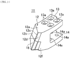
- Figure 3 is a perspective view of the auger bit
- Figure 4(a) is a plan view thereof
- Figure 4(b) is a side view thereof.
- an auger bit 11 includes a base part 12, and two leg parts 13 and 14 extending from the base part 12.
- a side closer to the base part 12 is also referred to as a leading end of the auger bit 11
- a side closer to the leg parts 13 and 14 is also referred to as an auger-head mounting side or a rear end of the auger bit 11.
- the base part 12 has what is called a chevron shape having a top part protruding toward the leading end side of the auger bit 11 in an axial direction of the auger head. More specifically, a plane part 12a of the base part 12 of the auger bit 11 is parallel to planes of the leg parts 13 and 14 and continuous with three tilted parts 12b, 12c, and 12d that are tilted toward the leading end side in the axial direction of the auger head.
- a left end of the tilted part 12b when viewed from the leading end side in the axial direction of the auger head is continuous with a side surface part 12e
- a right end of the tilted part 12d when viewed from the leading end side in the axial direction of the auger head is continuous with a side surface part 12f.
- the tilted parts 12b, 12c, and 12d of the base part 12 are continuous in the stated order in a lateral direction when viewed from the leading end side in the axial direction of the auger head, in other words, in a circumferential direction of the auger head.
- the tilted part 12b is tilted relative to the tilted part 12c in the circumferential direction of the auger head
- the tilted part 12d is tilted relative to the tilted part 12c in the circumferential direction of the auger head (direction opposite to a direction in which the tilted part 12b is tilted) of the tilted part 12b.
- tilted parts 12b, 12c, and 12d of the base part 12 are continuous with a tilted part 12g.
- the tilted part 12g is tilted toward the rear end side in the axial direction of the auger head, in other words, the auger-head mounting side of the auger bit 11 at 15° relative to a plane parallel to the plane part 12a.
- a hard building-up 16 is disposed at the base part 12.
- the leg parts 13 and 14 extend with a predetermined interval therebetween in a U shape from the base part 12 toward the rear end side in the axial direction of the auger head.
- the leg parts 13 and 14 are provided with four holes 13a and four holes 14a, respectively, for mounting the auger bit 11 on the auger head with bolts or the like.
- One superhard chip 15 is disposed at lower parts of the tilted parts 12b, 12c, and 12d of the base part 12 of the auger bit 11. With the superhard chip 15, abrasion outside a contact surface can be prevented. Moreover, the material and hardness of the superhard chip can be freely combined as appropriate in accordance with soil or an obstacle as an excavation target.
- parent materials of the leg parts 13 and 14 may be SCM440 (chromium/molybdenum steel) or the like.
- the material of the superhard chip 15 may be E3 (material name: MG30), E4 (material name: MG40), E5 (material name: MG50), E6 (material name: MG60), or the like among the JIS usage classification symbols or may be G4 (CIS material symbol: VC-40), G5 (CIS material symbol: VC-50), or the like in the CIS standard.
- the plane part 12a of the base part 12 and the leg parts 13 and 14 of the auger bit 11 each have an R shape curved relative to the axial direction of the auger head at a predetermined curvature in accordance with the diameter of the auger head.
- it is designed that leading ends of cutting edges are positioned on a circumference of ⁇ 850 mm, and the R shape has a curvature of R500 (inner periphery R395 (wide R shape)).
- the plane part and the like each have an R shape curved at a predetermined curvature in accordance with the diameter of the auger head, it is possible to prevent interference with a guide casing and thus reduce loss of cutting edges due to collision with the guide casing.
- the cutting edges are positioned not at middle positions but on the outer side so that excavation is performed further on the outer side than when the cutting edges are positioned at the middle positions, which enables not only securement of an excavation diameter but also size increase thereof.
- the R shape it is possible to reduce a load at excavation, thereby achieving improved excavation efficiency.
- Figure 5 is a perspective view of the auger bit
- Figure 6(a) is a side view thereof
- Figure 6(b) is a bottom view thereof.
- an auger bit 21 includes a base part 22, and two leg parts 23 and 24 extending from the base part 22.
- a side closer to the base part 22 is also referred to as a leading end of the auger bit 21, and a side closer to the leg parts 23 and 24 is also referred to as an auger-head mounting side or a rear end of the auger bit 21.
- the base part 22 has what is called a chevron shape having a top part protruding toward the leading end side of the auger bit 21 in an axial direction of the auger head. More specifically, a plane part 22a of the base part 22 of the auger bit 21 is parallel to planes of the leg parts 23 and 24 and continuous with three tilted parts 22b, 22c, and 22d that are tilted toward the leading end side in the axial direction of the auger head.
- a left end of the tilted part 22b when viewed from the leading end side in the axial direction of the auger head is continuous with a side surface part 22e
- a right end of the tilted part 22d when viewed from the leading end side in the axial direction of the auger head is continuous with a side surface part 22f.
- the tilted parts 22b, 22c, and 22d of the base part 22 are continuous in the stated order in a lateral direction when viewed from the leading end side in the axial direction of the auger head, in other words, in a circumferential direction of the auger head.
- the tilted part 22b is tilted relative to the tilted part 22c in the circumferential direction of the auger head
- the tilted part 22d is tilted relative to the tilted part 22c in the circumferential direction of the auger head (direction opposite to a direction in which the tilted part 22b is tilted) of the tilted part 22b.
- tilted parts 22b, 22c, and 22d of the base part 22 are continuous with a tilted part 22g.
- the tilted part 22g is tilted toward the rear end side in the axial direction of the auger head, in other words, the auger-head mounting side of the auger bit 21 at 15° relative to a plane parallel to the plane part 22a.
- a hard building-up 26 is disposed at the base part 22.
- the leg parts 23 and 24 extend with a predetermined interval therebetween in a U shape from the base part 22 toward the rear end side in the axial direction of the auger head.
- the leg parts 23 and 24 are provided with four holes 23a and four holes 24a, respectively, for mounting the auger bit 21 on the auger head with bolts or the like.
- One superhard chip 25 is disposed at lower parts of the tilted parts 22b, 22c, and 22d of the base part 22 of the auger bit 21. With the superhard chip 25, abrasion outside a contact surface can be prevented. Moreover, the materials and hardness of a plurality of superhard chips can be freely combined as appropriate in accordance with soil or an obstacle as an excavation target.
- parent materials of the leg parts 23 and 24 may be SCM440 (chromium/molybdenum steel) or the like.
- the material of the superhard chip 25 may be E3 (material name: MG30), E4 (material name: MG40), E5 (material name: MG50), E6 (material name: MG60), or the like among the JIS usage classification symbols or may be G4 (CIS material symbol: VC-40), G5 (CIS material symbol: VC-50), or the like in the CIS standard.
- the plane part 22a of the base part 22 and the leg parts 23 and 24 of the auger bit 21 have cutting edges wider than those of a typical auger bit. Specifically, a width of the plane part 22a in a direction orthogonal to the axial direction of the auger head, in other words, in the circumferential direction of the auger head is larger than that of a typical auger bit.
- the width of the plane part 22a in the direction orthogonal to the axial direction of the auger head is larger than that of a typical auger bit.
- a cutting edge width is equal to a holder width like the cutting edge width is 60 mm for a holder of 60 mm width and is 80 mm for a holder of 80 mm width
- the auger bit according to the present embodiment has such a wide shape that the cutting edge width is 85 mm for a holder of 60 mm width and is 105 mm for a holder of 80 mm width, and thus an already mounted holder can be used for the auger bit.
- auger bits can be used only by mounting the auger bits on existing holders.
- auger bits can be mounted by utilizing existing holders of the auger head.
- Figure 7 is a perspective view of the auger bit
- Figure 8(a) is a plan view thereof
- Figure 8(b) is a side view thereof.
- an auger bit 31 includes a base part 32, and two leg parts 33 and 34 extending from the base part 32.
- a side closer to the base part 32 is also referred to as a leading end of the auger bit 31
- a side closer to the leg parts 33 and 34 is also referred to as an auger-head mounting side or a rear end of the auger bit 31.
- the base part 32 has what is called a chevron shape having a top part protruding toward the leading end side of the auger bit 31 in an axial direction of the auger head. More specifically, a plane part 32a of the base part 32 of the auger bit 31 is parallel to planes of the leg parts 33 and 34 and continuous with three tilted parts 32b, 32c, and 32d that are tilted toward the leading end side in the axial direction of the auger head.
- a left end of the tilted part 32b when viewed from the leading end side in the axial direction of the auger head is continuous with a side surface part 32e
- a right end of the tilted part 32d when viewed from the leading end side in the axial direction of the auger head is continuous with a side surface part 32f.
- the tilted parts 32b, 32c, and 32d of the base part 32 are continuous in the stated order in a lateral direction when viewed from the leading end side in the axial direction of the auger head, in other words, in a circumferential direction of the auger head.
- the tilted part 32b is tilted relative to the tilted part 32c in the circumferential direction of the auger head
- the tilted part 32d is tilted relative to the tilted part 32c in the circumferential direction of the auger head (direction opposite to a direction in which the tilted part 32b is tilted) of the tilted part 32b.
- tilted parts 32b, 32c, and 32d of the base part 32 are continuous with a tilted part 32g.
- the tilted part 32g is tilted toward the rear end side in the axial direction of the auger head, in other words, the auger-head mounting side of the auger bit 31 at 15° relative to a plane parallel to the plane part 32a.
- a hard building-up 36 is disposed at the base part 32.
- the leg parts 33 and 34 extend with a predetermined interval therebetween in a U shape from the base part 32 toward the rear end side in the axial direction of the auger head.
- the leg parts 33 and 34 are provided with four holes 33a and four holes 34a, respectively, for mounting the auger bit 31 to the auger head with bolts or the like.
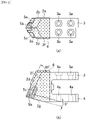
- Superhard chips 35a, 35b, and 35c are disposed at the tilted parts 32b, 32c, and 32d of the base part 32 of the auger bit 31. More specifically, the superhard chip 35a is disposed also across parts of the side surface part 32e and the tilted part 32g at a lower end part where the tilted part 32b is continuous with the side surface part 32e and the tilted part 32g. The superhard chip 35b is disposed also across a part of the tilted part 32g at a lower substantially central part of the tilted part 2b.
- the superhard chip 35c is disposed across the tilted parts 32b, 32c, and 32d, the side surface part 32f, and the tilted part 32g at a lower end part where the tilted parts 32b, 32c, and 32d, the side surface part 32f, and the tilted part 32g are continuous with each other.
- the superhard chips 35a to 35c With the superhard chips 35a to 35c, abrasion outside a contact surface can be prevented. Moreover, the materials and hardness of a plurality of superhard chips can be freely combined as appropriate in accordance with soil or an obstacle as an excavation target. For example, in the auger bit 31 according to the present embodiment, the superhard chips can be optionally selected from among superhard chips of five materials at maximum and used in combination so that loss and the like at excavation of a wide variety of excavation targets can be effectively prevented.
- parent materials of the leg parts 33 and 34 may be SCM440 (chromium/molybdenum steel) or the like.
- the materials of the superhard chips 35a to 35c may be E3 (material name: MG30), E4 (material name: MG40), E5 (material name: MG50), E6 (material name: MG60), or the like among the JIS usage classification symbols or may be G4 (CIS material symbol: VC-40), G5 (CIS material symbol: VC-50), or the like in the CIS standard.
- the plane part 32a of the base part 32 and the leg parts 33 and 34 of the auger bit 31 each have an R shape curved relative to the axial direction of the auger head at a predetermined curvature in accordance with the diameter of the auger head.
- it is designed that leading ends of cutting edges are positioned on a circumference of ⁇ 850 mm, and the R shape has a curvature of R475.
- the plane part 32a of the base part 32 and the leg parts 33 and 34 of the auger bit 31 have cutting edges wider than those of a typical auger bit. Specifically, a width of the plane part 32a in a direction orthogonal to the axial direction of the auger head, in other words, in the circumferential direction of the auger head is larger than that of a typical auger bit.
- the width of the plane part 32a in the direction orthogonal to the axial direction of the auger head is larger than that of a typical auger bit.
- a cutting edge width is equal to a holder width like the cutting edge width is 60 mm for a holder of 60 mm width and is 80 mm for a holder of 80 mm width, but the auger bit according to the fourth embodiment has such a wide shape that the cutting edge width is 85 mm for a holder of 60 mm width and is 105 mm for a holder of 80 mm width, and thus an already mounted holder can be used for the auger bit.
- the auger bit since the three divided superhard chips are provided, cutting edges of the auger bit are less likely to suffer loss and abrasion, thereby achieving improved excavation efficiency. Moreover, the auger bit needs to be less frequently replaced because not all superhard chips become unusable due to loss at one place unlike a configuration in which the superhard chips are integrated.
- the plane part of the base part has an R shape, it is possible to prevent interference with a guide casing and thus reduce loss of cutting edges due to collision with the guide casing.
- the cutting edges are positioned not at middle positions but on the outer side so that excavation is performed further on the outer side than when the cutting edges are positioned at the middle positions, which enables securement of an excavation diameter and size increase thereof.
- the R shape has a curvature in accordance with the diameter of the auger head, it is possible to reduce a load at excavation, thereby achieving improved excavation efficiency.
- auger bits can be mounted by utilizing existing holders of the auger head.
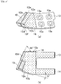
- Figure 9 is a perspective view of the auger bit
- Figure 10(a) is a plan view thereof
- Figure 10(b) is a side view thereof.
- an auger bit 41 includes a base part 42, and two leg parts 43 and 44 extending from the base part 42.
- a side closer to the base part 42 is also referred to as a leading end of the auger bit 41
- a side closer to the leg parts 43 and 44 is also referred to as an auger-head mounting side or a rear end of the auger bit 41.
- the base part 42 has what is called a chevron shape having a top part protruding toward the leading end side of the auger bit 41 in an axial direction of the auger head. More specifically, a plane part 42a of the base part 42 of the auger bit 41 is tilted downward at 15° toward the leading end side of the auger head relative to planes of the leg parts 43 and 44 and is continuous with three tilted parts 42b, 42c, and 42d that are further tilted toward the leading end side in the axial direction of the auger head.
- a left end of the tilted part 42b when viewed from the leading end side in the axial direction of the auger head is continuous with a side surface part 42e
- a right end of the tilted part 42d when viewed from the leading end side in the axial direction of the auger head is continuous with a side surface part 42f.
- the tilted parts 42b, 42c, and 42d of the base part 42 are continuous in the stated order in a lateral direction when viewed from the leading end side in the axial direction of the auger head, in other words, in a circumferential direction of the auger head.
- the tilted part 42b is tilted relative to the tilted part 42c in the circumferential direction of the auger head
- the tilted part 42d is tilted relative to the tilted part 42c in the circumferential direction of the auger head (direction opposite to a direction in which the tilted part 42b is tilted) of the tilted part 42b.
- tilted parts 42b, 42c, and 42d of the base part 42 are continuous with a tilted part 42g.
- the tilted part 42g is tilted toward the rear end side in the axial direction of the auger head, in other words, the auger-head mounting side of the auger bit 41 at 15° relative to a plane parallel to the plane part 42a.
- a hard building-up 46 is disposed at the base part 42.
- the leg parts 43 and 44 extend with a predetermined interval therebetween in a U shape from the base part 42 toward the rear end side in the axial direction of the auger head.
- the leg parts 43 and 44 are provided with four holes 43a and four holes 44a, respectively, for mounting the auger bit 41 on the auger head with bolts or the like.
- One superhard chip 45 is disposed at lower parts of the tilted parts 42b, 42c, and 42d of the base part 42 of the auger bit 41. With the superhard chip 45, abrasion outside a contact surface can be prevented. Moreover, the material and hardness of the superhard chip can be freely selected as appropriate in accordance with soil or an obstacle as an excavation target.
- parent materials of the leg parts 43 and 44 may be SCM440 (chromium/molybdenum steel) or the like.
- the material of the superhard chip 45 may be E3 (material name: MG30), E4 (material name: MG40), E5 (material name: MG50), E6 (material name: MG60), or the like among the JIS usage classification symbols or may be G4 (CIS material symbol: VC-40), G5 (CIS material symbol: VC-50), or the like in the CIS standard.
- the base part 42 of the auger bit 41 has a tapered elongated shape as compared to that of a typical auger bit and thus can provide a desirable bite into an excavation target, which leads to improved excavation efficiency.
- the cutting edge width is 60 mm for a holder of 60 mm width and is 80 mm for a holder of 80 mm width in a case of a typical auger bit, but the cutting edge width is 40 mm for a holder of 60 mm width and is 50 mm for a holder of 80 mm width in a case of the auger bit 41 according to the fifth embodiment.
- the plane part 42a of the base part 42 has such a tapered shape that the plane thereof has a maximum width of 80 mm and a minimum width of 50 mm, and the width gradually decreases from 80 mm to 50 mm as the position becomes closer to the leading end side.
- the cutting edge of a typical auger bit has a width of 60 mm and a length of 185 mm for a holder of 60 mm width and has a width of 80 mm and a length of 215 mm for a holder of 80 mm width
- the cutting edge of the auger bit 41 according to the fifth embodiment has a width of 40 mm and a length of 250 mm for a holder of 60 mm width, and has a width of 50 mm and a length of 280 mm or 310 mm for a holder of 80 mm width.
- the auger bit according to the fifth embodiment may be used together with an existing auger bit or may be used alone.
- three kinds of auger bits namely, normal auger bits of lengths 280 mm and 310 mm and the auger bit according to the present embodiment may be used together in a case in which the cutting edge has a width of 50 mm and a length of 280 mm or 310 mm for a holder of 80 mm width.
- the base part of the auger bit has a tapered elongated shape and thus can provide a desirable bite into an excavation target, which leads to improved excavation efficiency.
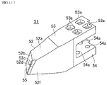
- Figure 11 is a perspective view of the auger bit
- Figure 12(a) is a plan view thereof
- Figure 12(b) is a side view thereof.
- an auger bit 51 includes a base part 52, and two leg parts 53 and 54 extending from the base part 52.
- a side closer to the base part 52 is also referred to as a leading end of the auger bit 51
- a side closer to the leg parts 53 and 54 is also referred to as an auger-head mounting side or a rear end of the auger bit 51.
- the base part 52 has what is called a chevron shape having a top part protruding toward the leading end side of the auger bit 51 in an axial direction of the auger head. More specifically, a plane part 52a of the base part 52 of the auger bit 51 is tilted downward at 15° toward the leading end side of the auger head relative to planes of the leg parts 53 and 54 and is continuous with three tilted parts 52b, 52c, and 52d that are further tilted toward the leading end side in the axial direction of the auger head.
- a left end of the tilted part 52b when viewed from the leading end side in the axial direction of the auger head is continuous with a side surface part 52e
- a right end of the tilted part 52d when viewed from the leading end side in the axial direction of the auger head is continuous with a side surface part 52f.
- the tilted parts 52b, 52c, and 52d of the base part 52 are continuous in the stated order in a lateral direction when viewed from the leading end side in the axial direction of the auger head, in other words, in a circumferential direction of the auger head.
- the tilted part 52b is tilted relative to the tilted part 52c in the circumferential direction of the auger head
- the tilted part 52d is tilted relative to the tilted part 52c in the circumferential direction of the auger head (direction opposite to a direction in which the tilted part 52b is tilted) of the tilted part 52b.
- tilted parts 52b, 52c, and 52d of the base part 52 are continuous with a tilted part 52g.
- the tilted part 52g is tilted toward the rear end side in the axial direction of the auger head, in other words, the auger-head mounting side of the auger bit 51 at 15° relative to a plane parallel to the plane part 52a.
- a hard building-up 56 is disposed at the base part 52.
- the leg parts 53 and 54 extend with a predetermined interval therebetween in a U shape from the base part 52 toward the rear end side in the axial direction of the auger head.
- the leg parts 53 and 54 are provided with four holes 53a and four holes 54a, respectively, for mounting the auger bit 51 to the auger head with bolts or the like.
- One superhard chip 55 is disposed at lower parts of the tilted parts 52b, 52c, and 52d of the base part 52 of the auger bit 51. With the superhard chip 55, abrasion outside a contact surface can be prevented. Moreover, the material and hardness of the superhard chip can be freely selected as appropriate in accordance with soil or an obstacle as an excavation target.
- parent materials of the leg parts 53 and 54 may be SCM440 (chromium/molybdenum steel) or the like.
- the material of the superhard chip 55 may be E3 (material name: MG30), E4 (material name: MG40), E5 (material name: MG50), E6 (material name: MG60), or the like among the JIS usage classification symbols or may be G4 (CIS material symbol: VC-40), G5 (CIS material symbol: VC-50), or the like in the CIS standard.
- the base part 52 of the auger bit 51 has a tapered elongated shape as compared to that of a typical auger bit and thus can provide a desirable bite into an excavation target, which leads to improved excavation efficiency.
- the cutting edge width is 60 mm for a holder of 60 mm width and is 80 mm for a holder of 80 mm width in a case of typical auger bit, but the cutting edge width is 40 mm for a holder of 60 mm width and is 50 mm for a holder of 80 mm width in a case of the auger bit 51 according to the present embodiment.
- the plane part 52a of the base part 52 has such a tapered shape that the plane thereof has a maximum width of 80 mm and a minimum width of 50 mm, and the width gradually decreases from 80 mm to 50 mm as the position becomes closer to the leading end side.
- the cutting edge of a typical auger bit has a width of 60 mm and a length of 185 mm for a holder of 60 mm width and has a width of 80 mm and a length of 215 mm for a holder of 80 mm width
- the cutting edge of the auger bit 51 according to the sixth embodiment has a width of 40 mm and a length of 250 mm for a holder of 60 mm width, and has a width of 50 mm and a length of 280 mm or 310 mm for a holder of 80 mm width.
- the auger bit according to the present embodiment may be used together with an existing auger bit or may be used alone.
- three kinds of auger bits namely, normal auger bits of lengths 280 mm and 310 mm and the auger bit according to the sixth embodiment may be used together in a case in which the cutting edge has a width of 50 mm and a length of 280 mm or 310 mm for a holder of 80 mm width.
- the plane part 52a of the base part 52 and the leg parts 53 and 54 of the auger bit 51 each have an R shape curved relative to the axial direction of the auger head at a predetermined curvature in accordance with the diameter of the auger head.
- it is designed that leading ends of cutting edges are positioned on a circumference of ⁇ 850 mm, and the R shape has a curvature of outer periphery R475 and inner periphery R395.
- the base part of the auger bit has a tapered elongated R shape and thus can provide a desirable bite into an excavation target, which leads to improved excavation efficiency.
- the plane part of the base part has an R shape, it is possible to prevent interference with a guide casing and thus reduce loss of cutting edges due to collision with the guide casing.
- the cutting edge of the base part is positioned not at a middle position but on the outer side so that excavation is performed further on the outer side than when the cutting edge is positioned at the middle position, which enables size increase of the excavation diameter.
- the R shape is curved at a predetermined curvature in accordance with the diameter of the auger head, it is possible to reduce a load at excavation, thereby achieving improved excavation efficiency.
- Figure 13(a) is a side view illustrating the attachment status
- Figure 13(b) is a front view illustrating the attachment status.
- an auger head 100 has what is called a screw shape, and at one of two bifurcated leading ends, an auger bit 101 according to the fourth embodiment and auger bits 102 and 103 according to the sixth embodiment are mounted in parallel in the stated order from outside toward a central part. At the other leading end, an auger bit 104 according to the fourth embodiment and an auger bit 105 according to the sixth embodiment are mounted in parallel in the stated order from outside toward the central part.
- the auger bits 101 and 104 according to the fourth embodiment are disposed on the outermost side and have R shapes approximate to the R shape of the auger head 100 and thus achieve smooth rotation and excavation, and moreover, the auger bits 101 and 104 have wide shapes and thus have high resistance against damage due to abrasion or the like.
- the auger bits 102, 103, and 105 according to the sixth embodiment are disposed toward the central part and have tapered elongated shapes, and can achieve desirable excavation irrespective of the kind of an excavation target.
- an auger bit for a casing auger according to each embodiment can be employed in, for example, work using an existing pile working method, a steel pipe inner excavation working method, or the like, and accordingly, crack, dropping, and abrasion of a superhard chip are less likely to occur during the work as compared to conventional cases.
Landscapes
- Engineering & Computer Science (AREA)
- Life Sciences & Earth Sciences (AREA)
- Mining & Mineral Resources (AREA)
- Geology (AREA)
- General Life Sciences & Earth Sciences (AREA)
- Physics & Mathematics (AREA)
- Mechanical Engineering (AREA)
- Environmental & Geological Engineering (AREA)
- Fluid Mechanics (AREA)
- Geochemistry & Mineralogy (AREA)
- Structural Engineering (AREA)
- General Engineering & Computer Science (AREA)
- Civil Engineering (AREA)
- Paleontology (AREA)
- Earth Drilling (AREA)
Abstract
Description
- The present invention relates to an auger bit for an auger head.
- In an existing pile working method using a pile driver, for example, an auger head is connected to a drive mechanism, a foundation hole for a building, a construction hole for a continuous underground wall, or the like is excavated in the ground, and a cutting part for excavation is provided to an auger bit provided at a leading end of the auger head. This is substantially same for a steel pipe inner excavation working method and the like.
- For example,
Patent Literature 1 discloses a removable earth auger bit including a bit body, a bit holder, and a coupling member, in which the bit body includes an excavation head including an excavation blade made of a superhard alloy, and a shank part provided continuously with the excavation head, the shank part includes a middle constriction part and circular parts and has a cross-section of a substantially 8-figure shape, a semi-opened retaining recess is formed at a substantially middle site in a longitudinal direction, the bit holder has a receiving hole that is drilled through an end face of the bit holder and into which the shank part is inserted, and also has an attachment hole drilled through each of upper and lower surfaces of the bit holder, intersecting the receiving hole, and having a hole shape complemented by the retaining recess of the shank part, and a middle part of the coupling member is positioned in the retaining recess of the shank part when the coupling member is inserted into the attachment hole of the bit holder. - Patent Literature 1:
Japanese Patent Laid-open No. 2002-339680 - However,
Patent Literature 1 merely discloses a removable earth auger bit and an earth auger that have an improved removable structure. - Conventionally, there have been no auger-head auger bit that has a tapered shape and an R shape curved at a predetermined curvature to achieve improved excavation efficiency, nor auger-head auger bit that has a larger bit width to avoid loss and improve abrasion resistance, improves the excavation efficiency while ensuring an excavation diameter, and further improves the excavation efficiency by preventing interference with a guide by employing an R shape.
- The present invention is achieved in view of such a problem and intended to provide an auger-head auger bit having improved excavation efficiency.
- To solve the above-described problem, an auger bit according to a first aspect of the present invention is an auger bit mounted on an auger head, the auger bit including: a base part having a leading end protruding in an axial direction of the auger head; and two leg parts continuously extending from the base part and facing each other at a predetermined interval, the base part includes a plane part parallel to and continuous with planes of the leg parts, a first tilted part that is tilted from the plane part toward a side closer to the leading end in the axial direction of the auger head, a second tilted part and a third tilted part that are continuous with the first tilted part, a first side surface part continuous with the second tilted part, a second side surface part continuous with the third tilted part, and a fourth tilted part that is tilted from the first to third tilted parts toward a side closer to the leg parts in the axial direction of the auger head, a superhard chip is disposed across parts of the first side surface part and the fourth tilted part at a lower end part where the second tilted part is continuous with the first side surface part and the fourth tilted part, a superhard chip is disposed across a part of the fourth tilted part at a lower substantially central part of the second tilted part, a superhard chip is disposed across the first to third tilted parts, the second side surface part, and the fourth tilted part at a lower end part where the first to third tilted parts are continuous with each other, the second side surface part, and the fourth tilted part, and the plane part and the leg parts each have a shape curved at a predetermined curvature relative to the axial direction of the auger head.
- An auger bit according to a second aspect of the present invention is the auger bit according to the first aspect in which the base part has a wide shape of a width of 85 mm to 105 mm in a width direction of the plane part of the auger head on the side closer to the leg parts.
- An auger bit according to a third aspect of the present invention is an auger bit mounted on an auger head, the auger bit including: a base part having a leading end protruding in an axial direction of the auger head; and two leg parts continuously extending from the base part and facing each other at a predetermined interval, the base part includes a plane part continuous with planes of the leg parts, a first tilted part that is tilted from the plane part toward a side closer to the leading end in the axial direction of the auger head, a side surface part continuous with the first tilted part, and a second tilted part tilted from the first tilted part toward the side closer to the leg parts in the axial direction of the auger head, the plane part of the base part has a tapered elongated shape of a width that gradually decreases toward the side closer to the leading end so that a length of a side along which the plane part is continuous with the first tilted part and the second tilted part on the side closer to the leading end is smaller than a length of a side along which the plane part is continuous with the one leg part on the side closer to the leg parts, and the plane part and the leg parts each have a shape curved at a predetermined curvature relative to the axial direction of the auger head.
- The present invention can provide an auger bit having improved excavation efficiency for a casing auger.
-
- [
Figure 1] Figure 1 is a perspective view of an auger bit according to a first embodiment of the present invention. - [
Figure 2] Figure 2 is a configuration diagram of the auger bit according to the first embodiment of the present invention. - [
Figure 3] Figure 3 is a perspective view of an auger bit according to a second embodiment of the present invention. - [
Figure 4] Figure 4 is a configuration diagram of the auger bit according to the second embodiment of the present invention. - [
Figure 5] Figure 5 is a perspective view of an auger bit according to a third embodiment of the present invention. - [
Figure 6] Figure 6 is a configuration diagram of the auger bit according to the third embodiment of the present invention. - [
Figure 7] Figure 7 is a perspective view of an auger bit according to a fourth embodiment of the present invention. - [
Figure 8] Figure 8 is a configuration diagram of the auger bit according to the fourth embodiment of the present invention. - [
Figure 9] Figure 9 is a perspective view of an auger bit according to a fifth embodiment of the present invention. - [
Figure 10] Figure 10 is a configuration diagram of the auger bit according to the fifth embodiment of the present invention. - [
Figure 11] Figure 11 is a perspective view of an auger bit according to a sixth embodiment of the present invention. - [
Figure 12] Figure 12 is a configuration diagram of the auger bit according to the sixth embodiment of the present invention. - [
Figure 13] Figure 13 is a diagram illustrating a status in which an auger bit is attached to an auger head. - Configurations and effects of auger bits for a casing auger according to first to sixth embodiments of the present invention will be described below in detail with reference to the accompanying drawings.
- The configuration of an auger bit according to a first embodiment of the present invention will be described below with reference to
Figures 1 ,2(a), and 2(b) . More specifically,Figure 1 is a perspective view of the auger bit,Figure 2(a) is a plan view thereof, andFigure 2(b) is a side view thereof. - As illustrated in these diagrams, an
auger bit 1 includes abase part 2, and twoleg parts base part 2. In the first embodiment, a side closer to thebase part 2 is also referred to as a leading end of theauger bit 1, and a side closer to theleg parts auger bit 1. - The
base part 2 has what is called a chevron shape having a top part protruding toward the leading end side of theauger bit 1 in an axial direction of an auger head. More specifically, a plane part 2a of thebase part 2 of theauger bit 1 is parallel to planes of theleg parts parts - In this example, a left end of the tilted
part 2b when viewed from the leading end side in the axial direction of the auger head is continuous with aside surface part 2e, and a right end of the tiltedpart 2d when viewed from the leading end side in the axial direction of the auger head is continuous with aside surface part 2f. - The tilted
parts base part 2 are continuous in the stated order in a lateral direction when viewed from the leading end side in the axial direction of the auger head, in other words, in a circumferential direction of the auger head. In this example, the tiltedpart 2b is tilted relative to the tiltedpart 2c in the circumferential direction of the auger head, and the tiltedpart 2d is tilted relative to the tiltedpart 2c in the circumferential direction of the auger head (direction opposite to the direction in which the tiltedpart 2c is tilted) of the tiltedpart 2b. - Lower ends of the tilted
parts base part 2 are continuous with atilted part 2g. The tiltedpart 2g is tilted toward the rear end side in the axial direction of the auger head, in other words, the auger-head mounting side of theauger bit 1 at 15° relative to a plane parallel to the plane part 2a. Note that, in this example, a hard building-up 6 is disposed at thebase part 2. - The
leg parts base part 2 toward the rear end side in the axial direction of the auger head. Theleg parts holes 3a and fourholes 4a, respectively, for mounting theauger bit 1 on the auger head with bolts or the like. -
Superhard chips parts base part 2 of theauger bit 1. More specifically, thesuperhard chip 5a is disposed also across a part of theside surface part 2e and the tiltedpart 2g at a lower end part where the tiltedpart 2b is continuous with theside surface part 2e and the tiltedpart 2g. Thesuperhard chip 5b is disposed across parts of the tiltedparts parts superhard chip 5c is disposed also across parts of theside surface part 2f and the tiltedpart 2g at a lower end part where the tiltedpart 2d is continuous with theside surface part 2f and the tiltedpart 2g. - With the
superhard chips 5a to 5c, abrasion outside a contact surface can be prevented. Moreover, the materials and hardness of a plurality of superhard chips can be freely combined as appropriate in accordance with soil or an obstacle as an excavation target. For example, in theauger bit 1 according to the first embodiment, the superhard chips can be optionally selected from among superhard chips of five materials at maximum and used in combination so that loss and the like at excavation of a wide variety of excavation targets can be effectively prevented. - The
base part 2 of theauger bit 1 has a shape bilaterally symmetric with respect to a target axis that is a line segment passing through the center of the plane part 2a in the axial direction of the auger head. In this manner, protection performance is increased with the bilaterally symmetric shape as well as a configuration in which respective surfaces of thetilted parts 2b to 2d and 2g are tilted at angles and superhard bits are arrayed at predetermined intervals as described above. - As for materials, parent materials of the
leg parts superhard chips 5a to 5c may be E3 (material name: MG30), E4 (material name: MG40), E5 (material name: MG50), E6 (material name: MG60), or the like among the JIS usage classification symbols or may be G4 (CIS material symbol: VC-40), G5 (CIS material symbol: VC-50), or the like in the CIS standard. - As described above, according to the first embodiment of the present invention, since the three divided superhard chips are provided, cutting edges of the auger bit are less likely to suffer loss and abrasion, thereby achieving improved excavation efficiency. Moreover, the auger bit needs to be less frequently replaced because not all superhard chips become unusable due to loss at one place unlike a configuration in which the superhard chips are integrated.
- The configuration of an auger bit according to a second embodiment of the present invention will be described below with reference to
Figures 3 ,4(a), and 4(b) . More specifically,Figure 3 is a perspective view of the auger bit,Figure 4(a) is a plan view thereof, andFigure 4(b) is a side view thereof. - As illustrated in these diagrams, an
auger bit 11 includes abase part 12, and twoleg parts base part 12. In the second embodiment, a side closer to thebase part 12 is also referred to as a leading end of theauger bit 11, and a side closer to theleg parts auger bit 11. - The
base part 12 has what is called a chevron shape having a top part protruding toward the leading end side of theauger bit 11 in an axial direction of the auger head. More specifically, aplane part 12a of thebase part 12 of theauger bit 11 is parallel to planes of theleg parts parts - In this example, a left end of the tilted
part 12b when viewed from the leading end side in the axial direction of the auger head is continuous with aside surface part 12e, and a right end of the tiltedpart 12d when viewed from the leading end side in the axial direction of the auger head is continuous with aside surface part 12f. - The tilted
parts base part 12 are continuous in the stated order in a lateral direction when viewed from the leading end side in the axial direction of the auger head, in other words, in a circumferential direction of the auger head. In this example, the tiltedpart 12b is tilted relative to the tiltedpart 12c in the circumferential direction of the auger head, and the tiltedpart 12d is tilted relative to the tiltedpart 12c in the circumferential direction of the auger head (direction opposite to a direction in which the tiltedpart 12b is tilted) of the tiltedpart 12b. - Lower ends of the tilted
parts base part 12 are continuous with atilted part 12g. The tiltedpart 12g is tilted toward the rear end side in the axial direction of the auger head, in other words, the auger-head mounting side of theauger bit 11 at 15° relative to a plane parallel to theplane part 12a. Note that, in this example, a hard building-up 16 is disposed at thebase part 12. - The
leg parts base part 12 toward the rear end side in the axial direction of the auger head. Theleg parts holes 13a and fourholes 14a, respectively, for mounting theauger bit 11 on the auger head with bolts or the like. - One
superhard chip 15 is disposed at lower parts of the tiltedparts base part 12 of theauger bit 11. With thesuperhard chip 15, abrasion outside a contact surface can be prevented. Moreover, the material and hardness of the superhard chip can be freely combined as appropriate in accordance with soil or an obstacle as an excavation target. - As for the material of each component, parent materials of the
leg parts superhard chip 15 may be E3 (material name: MG30), E4 (material name: MG40), E5 (material name: MG50), E6 (material name: MG60), or the like among the JIS usage classification symbols or may be G4 (CIS material symbol: VC-40), G5 (CIS material symbol: VC-50), or the like in the CIS standard. - The
plane part 12a of thebase part 12 and theleg parts auger bit 11 each have an R shape curved relative to the axial direction of the auger head at a predetermined curvature in accordance with the diameter of the auger head. In this example, it is designed that leading ends of cutting edges are positioned on a circumference of φ850 mm, and the R shape has a curvature of R500 (inner periphery R395 (wide R shape)). With such a configuration, efficiency of excavation at the outer periphery of the auger head can be improved when a holder dedicated for the auger head is used together. - As described above, according to the second embodiment of the present invention, since the plane part and the like each have an R shape curved at a predetermined curvature in accordance with the diameter of the auger head, it is possible to prevent interference with a guide casing and thus reduce loss of cutting edges due to collision with the guide casing. In addition, with the R shape, the cutting edges are positioned not at middle positions but on the outer side so that excavation is performed further on the outer side than when the cutting edges are positioned at the middle positions, which enables not only securement of an excavation diameter but also size increase thereof. Moreover, with the R shape, it is possible to reduce a load at excavation, thereby achieving improved excavation efficiency.
- The configuration of an auger bit according to a third embodiment of the present invention will be described below with reference to
Figures 5 ,6(a), and 6(b) . More specifically,Figure 5 is a perspective view of the auger bit,Figure 6(a) is a side view thereof, andFigure 6(b) is a bottom view thereof. - As illustrated in these diagrams, an
auger bit 21 includes abase part 22, and twoleg parts base part 22. In the second embodiment, a side closer to thebase part 22 is also referred to as a leading end of theauger bit 21, and a side closer to theleg parts auger bit 21. - The
base part 22 has what is called a chevron shape having a top part protruding toward the leading end side of theauger bit 21 in an axial direction of the auger head. More specifically, aplane part 22a of thebase part 22 of theauger bit 21 is parallel to planes of theleg parts parts - In this example, a left end of the tilted
part 22b when viewed from the leading end side in the axial direction of the auger head is continuous with a side surface part 22e, and a right end of the tiltedpart 22d when viewed from the leading end side in the axial direction of the auger head is continuous with aside surface part 22f. - The tilted
parts base part 22 are continuous in the stated order in a lateral direction when viewed from the leading end side in the axial direction of the auger head, in other words, in a circumferential direction of the auger head. In this example, the tiltedpart 22b is tilted relative to the tiltedpart 22c in the circumferential direction of the auger head, and the tiltedpart 22d is tilted relative to the tiltedpart 22c in the circumferential direction of the auger head (direction opposite to a direction in which the tiltedpart 22b is tilted) of the tiltedpart 22b. - Lower ends of the tilted
parts base part 22 are continuous with atilted part 22g. The tiltedpart 22g is tilted toward the rear end side in the axial direction of the auger head, in other words, the auger-head mounting side of theauger bit 21 at 15° relative to a plane parallel to theplane part 22a. Note that, in this example, a hard building-up 26 is disposed at thebase part 22. - The
leg parts base part 22 toward the rear end side in the axial direction of the auger head. Theleg parts holes 23a and fourholes 24a, respectively, for mounting theauger bit 21 on the auger head with bolts or the like. - One
superhard chip 25 is disposed at lower parts of the tiltedparts base part 22 of theauger bit 21. With thesuperhard chip 25, abrasion outside a contact surface can be prevented. Moreover, the materials and hardness of a plurality of superhard chips can be freely combined as appropriate in accordance with soil or an obstacle as an excavation target. - As for the material of each component, parent materials of the
leg parts superhard chip 25 may be E3 (material name: MG30), E4 (material name: MG40), E5 (material name: MG50), E6 (material name: MG60), or the like among the JIS usage classification symbols or may be G4 (CIS material symbol: VC-40), G5 (CIS material symbol: VC-50), or the like in the CIS standard. - The
plane part 22a of thebase part 22 and theleg parts auger bit 21 have cutting edges wider than those of a typical auger bit. Specifically, a width of theplane part 22a in a direction orthogonal to the axial direction of the auger head, in other words, in the circumferential direction of the auger head is larger than that of a typical auger bit. - More specifically, the width of the
plane part 22a in the direction orthogonal to the axial direction of the auger head is larger than that of a typical auger bit. For example, it is typical that, in a typical auger bit for a casing auger, a cutting edge width is equal to a holder width like the cutting edge width is 60 mm for a holder of 60 mm width and is 80 mm for a holder of 80 mm width, but the auger bit according to the present embodiment has such a wide shape that the cutting edge width is 85 mm for a holder of 60 mm width and is 105 mm for a holder of 80 mm width, and thus an already mounted holder can be used for the auger bit. - Conventionally, to increase the width of the auger head, it has been needed to increase the sizes of holders or weld auger bits for an auger of 20 to 25 mm width, but with the above-described configuration, auger bits can be used only by mounting the auger bits on existing holders.
- As described above, according to the third embodiment of the present invention, loss and abrasion of auger bits can be prevented with the wide shape. Moreover, auger bits can be mounted by utilizing existing holders of the auger head.
- The configuration of an auger bit according to a fourth embodiment of the present invention will be described below with reference to
Figures 7 ,8(a), and 8(b) . More specifically,Figure 7 is a perspective view of the auger bit,Figure 8(a) is a plan view thereof, andFigure 8(b) is a side view thereof. - As illustrated in these diagrams, an
auger bit 31 includes abase part 32, and twoleg parts base part 32. In the fourth embodiment, a side closer to thebase part 32 is also referred to as a leading end of theauger bit 31, and a side closer to theleg parts auger bit 31. - The
base part 32 has what is called a chevron shape having a top part protruding toward the leading end side of theauger bit 31 in an axial direction of the auger head. More specifically, aplane part 32a of thebase part 32 of theauger bit 31 is parallel to planes of theleg parts parts - In this example, a left end of the tilted
part 32b when viewed from the leading end side in the axial direction of the auger head is continuous with aside surface part 32e, and a right end of the tiltedpart 32d when viewed from the leading end side in the axial direction of the auger head is continuous with aside surface part 32f. - The tilted
parts base part 32 are continuous in the stated order in a lateral direction when viewed from the leading end side in the axial direction of the auger head, in other words, in a circumferential direction of the auger head. In this example, the tiltedpart 32b is tilted relative to the tiltedpart 32c in the circumferential direction of the auger head, and the tiltedpart 32d is tilted relative to the tiltedpart 32c in the circumferential direction of the auger head (direction opposite to a direction in which the tiltedpart 32b is tilted) of the tiltedpart 32b. - Lower ends of the tilted
parts base part 32 are continuous with a tilted part 32g. The tilted part 32g is tilted toward the rear end side in the axial direction of the auger head, in other words, the auger-head mounting side of theauger bit 31 at 15° relative to a plane parallel to theplane part 32a. Note that, in this example, a hard building-up 36 is disposed at thebase part 32. - The
leg parts base part 32 toward the rear end side in the axial direction of the auger head. Theleg parts holes 33a and fourholes 34a, respectively, for mounting theauger bit 31 to the auger head with bolts or the like. -
Superhard chips parts base part 32 of theauger bit 31. More specifically, thesuperhard chip 35a is disposed also across parts of theside surface part 32e and the tilted part 32g at a lower end part where the tiltedpart 32b is continuous with theside surface part 32e and the tilted part 32g. Thesuperhard chip 35b is disposed also across a part of the tilted part 32g at a lower substantially central part of the tiltedpart 2b. Thesuperhard chip 35c is disposed across the tiltedparts side surface part 32f, and the tilted part 32g at a lower end part where the tiltedparts side surface part 32f, and the tilted part 32g are continuous with each other. - With the
superhard chips 35a to 35c, abrasion outside a contact surface can be prevented. Moreover, the materials and hardness of a plurality of superhard chips can be freely combined as appropriate in accordance with soil or an obstacle as an excavation target. For example, in theauger bit 31 according to the present embodiment, the superhard chips can be optionally selected from among superhard chips of five materials at maximum and used in combination so that loss and the like at excavation of a wide variety of excavation targets can be effectively prevented. - As for materials, parent materials of the
leg parts superhard chips 35a to 35c may be E3 (material name: MG30), E4 (material name: MG40), E5 (material name: MG50), E6 (material name: MG60), or the like among the JIS usage classification symbols or may be G4 (CIS material symbol: VC-40), G5 (CIS material symbol: VC-50), or the like in the CIS standard. - The
plane part 32a of thebase part 32 and theleg parts auger bit 31 each have an R shape curved relative to the axial direction of the auger head at a predetermined curvature in accordance with the diameter of the auger head. In the present example, it is designed that leading ends of cutting edges are positioned on a circumference of φ850 mm, and the R shape has a curvature of R475. With such a configuration, efficiency of excavation at the outer periphery of the auger head can be improved when a holder dedicated for the auger head is used together. - The
plane part 32a of thebase part 32 and theleg parts auger bit 31 have cutting edges wider than those of a typical auger bit. Specifically, a width of theplane part 32a in a direction orthogonal to the axial direction of the auger head, in other words, in the circumferential direction of the auger head is larger than that of a typical auger bit. - Specifically, the width of the
plane part 32a in the direction orthogonal to the axial direction of the auger head is larger than that of a typical auger bit. - For example, it is typical that, in a typical auger bit for a casing auger, a cutting edge width is equal to a holder width like the cutting edge width is 60 mm for a holder of 60 mm width and is 80 mm for a holder of 80 mm width, but the auger bit according to the fourth embodiment has such a wide shape that the cutting edge width is 85 mm for a holder of 60 mm width and is 105 mm for a holder of 80 mm width, and thus an already mounted holder can be used for the auger bit.
- As described above, according to the fourth embodiment of the present invention, since the three divided superhard chips are provided, cutting edges of the auger bit are less likely to suffer loss and abrasion, thereby achieving improved excavation efficiency. Moreover, the auger bit needs to be less frequently replaced because not all superhard chips become unusable due to loss at one place unlike a configuration in which the superhard chips are integrated.
- In addition, according to the fourth embodiment, since the plane part of the base part has an R shape, it is possible to prevent interference with a guide casing and thus reduce loss of cutting edges due to collision with the guide casing. The cutting edges are positioned not at middle positions but on the outer side so that excavation is performed further on the outer side than when the cutting edges are positioned at the middle positions, which enables securement of an excavation diameter and size increase thereof. Moreover, since the R shape has a curvature in accordance with the diameter of the auger head, it is possible to reduce a load at excavation, thereby achieving improved excavation efficiency.
- In addition, according to the fourth embodiment, loss and abrasion of auger bits can be prevented with the wide shape. Moreover, auger bits can be mounted by utilizing existing holders of the auger head.
- The configuration of an auger bit according to a fifth embodiment of the present invention will be described below with reference to
Figures 9 ,10(a), and 10(b) . More specifically,Figure 9 is a perspective view of the auger bit,Figure 10(a) is a plan view thereof, andFigure 10(b) is a side view thereof. - As illustrated in these diagrams, an
auger bit 41 includes abase part 42, and twoleg parts base part 42. In the fifth embodiment, a side closer to thebase part 42 is also referred to as a leading end of theauger bit 41, and a side closer to theleg parts auger bit 41. - The
base part 42 has what is called a chevron shape having a top part protruding toward the leading end side of theauger bit 41 in an axial direction of the auger head. More specifically, aplane part 42a of thebase part 42 of theauger bit 41 is tilted downward at 15° toward the leading end side of the auger head relative to planes of theleg parts parts - In this example, a left end of the tilted
part 42b when viewed from the leading end side in the axial direction of the auger head is continuous with a side surface part 42e, and a right end of the tiltedpart 42d when viewed from the leading end side in the axial direction of the auger head is continuous with aside surface part 42f. - The tilted
parts base part 42 are continuous in the stated order in a lateral direction when viewed from the leading end side in the axial direction of the auger head, in other words, in a circumferential direction of the auger head. In this example, the tiltedpart 42b is tilted relative to the tiltedpart 42c in the circumferential direction of the auger head, and the tiltedpart 42d is tilted relative to the tiltedpart 42c in the circumferential direction of the auger head (direction opposite to a direction in which the tiltedpart 42b is tilted) of the tiltedpart 42b. - Lower ends of the tilted
parts base part 42 are continuous with atilted part 42g. The tiltedpart 42g is tilted toward the rear end side in the axial direction of the auger head, in other words, the auger-head mounting side of theauger bit 41 at 15° relative to a plane parallel to theplane part 42a. Note that, in this example, a hard building-up 46 is disposed at thebase part 42. - The
leg parts base part 42 toward the rear end side in the axial direction of the auger head. Theleg parts holes 43a and fourholes 44a, respectively, for mounting theauger bit 41 on the auger head with bolts or the like. - One
superhard chip 45 is disposed at lower parts of the tiltedparts base part 42 of theauger bit 41. With thesuperhard chip 45, abrasion outside a contact surface can be prevented. Moreover, the material and hardness of the superhard chip can be freely selected as appropriate in accordance with soil or an obstacle as an excavation target. - As for the material of each component, parent materials of the
leg parts superhard chip 45 may be E3 (material name: MG30), E4 (material name: MG40), E5 (material name: MG50), E6 (material name: MG60), or the like among the JIS usage classification symbols or may be G4 (CIS material symbol: VC-40), G5 (CIS material symbol: VC-50), or the like in the CIS standard. - The
base part 42 of theauger bit 41 has a tapered elongated shape as compared to that of a typical auger bit and thus can provide a desirable bite into an excavation target, which leads to improved excavation efficiency. - More specifically, the cutting edge width is 60 mm for a holder of 60 mm width and is 80 mm for a holder of 80 mm width in a case of a typical auger bit, but the cutting edge width is 40 mm for a holder of 60 mm width and is 50 mm for a holder of 80 mm width in a case of the
auger bit 41 according to the fifth embodiment. In the illustrated example, theplane part 42a of thebase part 42 has such a tapered shape that the plane thereof has a maximum width of 80 mm and a minimum width of 50 mm, and the width gradually decreases from 80 mm to 50 mm as the position becomes closer to the leading end side. - Moreover, the cutting edge of a typical auger bit has a width of 60 mm and a length of 185 mm for a holder of 60 mm width and has a width of 80 mm and a length of 215 mm for a holder of 80 mm width, but the cutting edge of the
auger bit 41 according to the fifth embodiment has a width of 40 mm and a length of 250 mm for a holder of 60 mm width, and has a width of 50 mm and a length of 280 mm or 310 mm for a holder of 80 mm width. - The auger bit according to the fifth embodiment may be used together with an existing auger bit or may be used alone. Specifically, for example, three kinds of auger bits, namely, normal auger bits of lengths 280 mm and 310 mm and the auger bit according to the present embodiment may be used together in a case in which the cutting edge has a width of 50 mm and a length of 280 mm or 310 mm for a holder of 80 mm width.
- As described above, according to the fifth embodiment of the present invention, the base part of the auger bit has a tapered elongated shape and thus can provide a desirable bite into an excavation target, which leads to improved excavation efficiency.
- The configuration of an auger bit according to a sixth embodiment of the present invention will be described below with reference to
Figures 11 ,12(a), and 12(b) . More specifically,Figure 11 is a perspective view of the auger bit,Figure 12(a) is a plan view thereof, andFigure 12(b) is a side view thereof. - As illustrated in these diagrams, an
auger bit 51 includes abase part 52, and twoleg parts base part 52. In the sixth embodiment, a side closer to thebase part 52 is also referred to as a leading end of theauger bit 51, a side closer to theleg parts auger bit 51. - The
base part 52 has what is called a chevron shape having a top part protruding toward the leading end side of theauger bit 51 in an axial direction of the auger head. More specifically, aplane part 52a of thebase part 52 of theauger bit 51 is tilted downward at 15° toward the leading end side of the auger head relative to planes of theleg parts parts - In this example, a left end of the tilted
part 52b when viewed from the leading end side in the axial direction of the auger head is continuous with a side surface part 52e, and a right end of the tiltedpart 52d when viewed from the leading end side in the axial direction of the auger head is continuous with aside surface part 52f. - The tilted
parts base part 52 are continuous in the stated order in a lateral direction when viewed from the leading end side in the axial direction of the auger head, in other words, in a circumferential direction of the auger head. In this example, the tiltedpart 52b is tilted relative to the tiltedpart 52c in the circumferential direction of the auger head, and the tiltedpart 52d is tilted relative to the tiltedpart 52c in the circumferential direction of the auger head (direction opposite to a direction in which the tiltedpart 52b is tilted) of the tiltedpart 52b. - Lower ends of the tilted
parts base part 52 are continuous with atilted part 52g. The tiltedpart 52g is tilted toward the rear end side in the axial direction of the auger head, in other words, the auger-head mounting side of theauger bit 51 at 15° relative to a plane parallel to theplane part 52a. Note that, in this example, a hard building-up 56 is disposed at thebase part 52. - The
leg parts base part 52 toward the rear end side in the axial direction of the auger head. Theleg parts holes 53a and fourholes 54a, respectively, for mounting theauger bit 51 to the auger head with bolts or the like. - One
superhard chip 55 is disposed at lower parts of the tiltedparts base part 52 of theauger bit 51. With thesuperhard chip 55, abrasion outside a contact surface can be prevented. Moreover, the material and hardness of the superhard chip can be freely selected as appropriate in accordance with soil or an obstacle as an excavation target. - As for the material of each component, parent materials of the
leg parts superhard chip 55 may be E3 (material name: MG30), E4 (material name: MG40), E5 (material name: MG50), E6 (material name: MG60), or the like among the JIS usage classification symbols or may be G4 (CIS material symbol: VC-40), G5 (CIS material symbol: VC-50), or the like in the CIS standard. - The
base part 52 of theauger bit 51 has a tapered elongated shape as compared to that of a typical auger bit and thus can provide a desirable bite into an excavation target, which leads to improved excavation efficiency. - More specifically, the cutting edge width is 60 mm for a holder of 60 mm width and is 80 mm for a holder of 80 mm width in a case of typical auger bit, but the cutting edge width is 40 mm for a holder of 60 mm width and is 50 mm for a holder of 80 mm width in a case of the
auger bit 51 according to the present embodiment. In the illustrated example, theplane part 52a of thebase part 52 has such a tapered shape that the plane thereof has a maximum width of 80 mm and a minimum width of 50 mm, and the width gradually decreases from 80 mm to 50 mm as the position becomes closer to the leading end side. - Moreover, the cutting edge of a typical auger bit has a width of 60 mm and a length of 185 mm for a holder of 60 mm width and has a width of 80 mm and a length of 215 mm for a holder of 80 mm width, but the cutting edge of the
auger bit 51 according to the sixth embodiment has a width of 40 mm and a length of 250 mm for a holder of 60 mm width, and has a width of 50 mm and a length of 280 mm or 310 mm for a holder of 80 mm width. - The auger bit according to the present embodiment may be used together with an existing auger bit or may be used alone. Specifically, for example, three kinds of auger bits, namely, normal auger bits of lengths 280 mm and 310 mm and the auger bit according to the sixth embodiment may be used together in a case in which the cutting edge has a width of 50 mm and a length of 280 mm or 310 mm for a holder of 80 mm width.
- The
plane part 52a of thebase part 52 and theleg parts auger bit 51 each have an R shape curved relative to the axial direction of the auger head at a predetermined curvature in accordance with the diameter of the auger head. In the present embodiment, it is designed that leading ends of cutting edges are positioned on a circumference of φ850 mm, and the R shape has a curvature of outer periphery R475 and inner periphery R395. With such a configuration, efficiency of excavation at the outer periphery of the auger head can be improved when a holder dedicated for the auger head is used together. - As described above, according to the sixth embodiment of the present invention, the base part of the auger bit has a tapered elongated R shape and thus can provide a desirable bite into an excavation target, which leads to improved excavation efficiency.
- Moreover, since the plane part of the base part has an R shape, it is possible to prevent interference with a guide casing and thus reduce loss of cutting edges due to collision with the guide casing. In addition, the cutting edge of the base part is positioned not at a middle position but on the outer side so that excavation is performed further on the outer side than when the cutting edge is positioned at the middle position, which enables size increase of the excavation diameter. Furthermore, since the R shape is curved at a predetermined curvature in accordance with the diameter of the auger head, it is possible to reduce a load at excavation, thereby achieving improved excavation efficiency.
- Lastly, a status in which the auger bits according to the fourth embodiment and the sixth embodiment are attached to the auger head will be described with reference to
Figure 13 . More specifically,Figure 13(a) is a side view illustrating the attachment status, andFigure 13(b) is a front view illustrating the attachment status. - As illustrated in these diagrams, an
auger head 100 has what is called a screw shape, and at one of two bifurcated leading ends, anauger bit 101 according to the fourth embodiment andauger bits auger bit 104 according to the fourth embodiment and anauger bit 105 according to the sixth embodiment are mounted in parallel in the stated order from outside toward the central part. In this manner, theauger bits auger head 100 and thus achieve smooth rotation and excavation, and moreover, theauger bits auger bits - The first to sixth embodiments of the present invention are described above, but the present invention is not limited thereto and may be modified and changed in various kinds of manners without departing from the scope of the present invention.
- For example, an auger bit for a casing auger according to each embodiment can be employed in, for example, work using an existing pile working method, a steel pipe inner excavation working method, or the like, and accordingly, crack, dropping, and abrasion of a superhard chip are less likely to occur during the work as compared to conventional cases.
-
- 1 auger bit
- 2 base part
- 2a plane part
- 2b, 2c, 2d tilted part
- 2e, 2f side surface part
- 2g tilted part
- 3 leg part
- 3a hole
- 4 leg part
- 4a hole
- 5a, 5b, 5c superhard chip
- 6 hard building-up
- 11 auger bit
- 12 base part
- 12a plane part
- 12b, 12c, 12d tilted part
- 12e, 12f side surface part
- 12g tilted part
- 13 leg part
- 13a hole
- 14 leg part
- 14a hole
- 15 superhard chip
- 16 hard building-up
- 21 auger bit
- 22 base part
- 22a plane part
- 22b, 22c, 22d tilted part
- 22e, 22f side surface part
- 22g tilted part
- 23 leg part
- 23a hole
- 24 leg part
- 24a hole
- 25 superhard chip
- 26 hard building-up
- 31 auger bit
- 32 base part
- 32a plane part
- 32b, 32c, 32d tilted part
- 32e, 32f side surface part
- 32g tilted part
- 33 leg part
- 33a hole
- 34 leg part
- 34a hole
- 35a, 35b, 35c superhard chip
- 36 hard building-up
- 41 auger bit
- 42 base part
- 42a plane part
- 42b, 42c, 42d tilted part
- 42e, 42f side surface part
- 42g tilted part
- 43 leg part
- 43a hole
- 44 leg part
- 44a hole
- 45 superhard chip
- 46 hard building-up
- 51 auger bit
- 52 base part
- 52a plane part
- 52b, 52c, 52d tilted part
- 52e, 52f side surface part
- 52g tilted part
- 53 leg part
- 53a hole
- 54 leg part
- 54a hole
- 55 superhard chip
- 56 hard building-up
Claims (3)
- An auger bit mounted on an auger head, the auger bit comprising:a base part having a leading end protruding in an axial direction of the auger head; andtwo leg parts continuously extending from the base part and facing each other at a predetermined interval, whereinthe base part includes a plane part parallel to and continuous with planes of the leg parts, a first tilted part that is tilted from the plane part toward a side closer to the leading end in the axial direction of the auger head, a second tilted part and a third tilted part that are continuous with the first tilted part, a first side surface part continuous with the second tilted part, a second side surface part continuous with the third tilted part, and a fourth tilted part that is tilted from the first to third tilted parts toward a side closer to the leg parts in the axial direction of the auger head,a superhard chip is disposed across parts of the first side surface part and the fourth tilted part at a lower end part where the second tilted part is continuous with the first side surface part and the fourth tilted part, a superhard chip is disposed across a part of the fourth tilted part at a lower substantially central part of the second tilted part, and a superhard chip is disposed across the first to third tilted parts, the second side surface part, and the fourth tilted part at a lower end part where the first to third tilted parts are continuous with each other, the second side surface part, and the fourth tilted part, andthe plane part and the leg parts each have a shape curved at a predetermined curvature relative to the axial direction of the auger head.
- The auger bit according to claim 1, wherein the base part has a wide shape of a width of 85 mm to 105 mm in a width direction of the plane part of the auger head on the side closer to the leg parts.
- An auger bit mounted on an auger head, the auger bit comprising:a base part having a leading end protruding in an axial direction of the auger head; andtwo leg parts continuously extending from the base part and facing each other at a predetermined interval, whereinthe base part includes a plane part continuous with planes of the leg parts, a first tilted part that is tilted from the plane part toward a side closer to the leading end in the axial direction of the auger head, a side surface part continuous with the first tilted part, and a second tilted part tilted from the first tilted part toward the side closer to the leg parts in the axial direction of the auger head,the plane part of the base part has a tapered elongated shape of a width that gradually decreases toward the side closer to the leading end so that a length of a side along which the plane part is continuous with the first tilted part and the second tilted part on the side closer to the leading end is smaller than a length of a side along which the plane part is continuous with the one leg part on the side closer to the leg parts, andthe plane part and the leg parts each have a shape curved at a predetermined curvature relative to the axial direction of the auger head.
Applications Claiming Priority (2)
| Application Number | Priority Date | Filing Date | Title |
|---|---|---|---|
| JP2019095191A JP6628459B1 (en) | 2019-05-21 | 2019-05-21 | Auger bit |
| PCT/JP2020/019046 WO2020235407A1 (en) | 2019-05-21 | 2020-05-13 | Auger bit |
Publications (2)
| Publication Number | Publication Date |
|---|---|
| EP3974615A1 true EP3974615A1 (en) | 2022-03-30 |
| EP3974615A4 EP3974615A4 (en) | 2023-05-24 |
Family
ID=69101141
Family Applications (1)
| Application Number | Title | Priority Date | Filing Date |
|---|---|---|---|
| EP20808910.2A Pending EP3974615A4 (en) | 2019-05-21 | 2020-05-13 | Auger bit |
Country Status (6)
| Country | Link |
|---|---|
| US (1) | US11795765B2 (en) |
| EP (1) | EP3974615A4 (en) |
| JP (1) | JP6628459B1 (en) |
| KR (1) | KR102632811B1 (en) |
| CN (1) | CN113994067A (en) |
| WO (1) | WO2020235407A1 (en) |
Family Cites Families (40)
| Publication number | Priority date | Publication date | Assignee | Title |
|---|---|---|---|---|
| US2005016A (en) * | 1932-06-27 | 1935-06-18 | Lesher W Van Buskirk | Digging tooth |
| US2510751A (en) * | 1944-04-08 | 1950-06-06 | Mclaughlin Joseph | Auger bit head |
| US3207242A (en) * | 1963-10-11 | 1965-09-21 | Alaskaug Inc | Earth auger with integral mounting for cutting members |
| US3300883A (en) * | 1963-10-21 | 1967-01-31 | Petersen | Reversible digging tooth with three cutting edges |
| US3316988A (en) * | 1964-09-21 | 1967-05-02 | Petersen Anita E | Auger head with three radial arms |
| US3375890A (en) * | 1965-12-20 | 1968-04-02 | Petersen Anita E | Earth auger construction |
| US3426860A (en) * | 1966-12-27 | 1969-02-11 | Gerald A Petersen | Pilot bit with replaceable teeth |
| US3999620A (en) * | 1975-05-30 | 1976-12-28 | Watson, Incorporated | Core barrel |
| FR2379695A1 (en) * | 1977-02-03 | 1978-09-01 | Bourlier Jacques | TEETH FOR FOUNDATION DRILLING TOOL WITH ROTARY MOVEMENT |
| JPS56115494A (en) * | 1980-02-15 | 1981-09-10 | Nippon Tungsten | Earth auger bit |
| JPS5747085A (en) * | 1980-09-05 | 1982-03-17 | Tokyo Gas Co Ltd | Inner lining method of pipeline |
| JPS58115592U (en) * | 1982-02-01 | 1983-08-06 | 日本タングステン株式会社 | Cutter bit for rock excavation cutter equipment |
| JPS58149491U (en) * | 1982-03-31 | 1983-10-07 | 株式会社菱備基礎 | Earth auger head for excavating faulty ground |
| JPS59121090U (en) * | 1983-02-01 | 1984-08-15 | 住友電気工業株式会社 | Mounting structure of removable digging claw for earth auger |
| JPS60115991U (en) * | 1984-01-12 | 1985-08-06 | 村崎 和雄 | Ground auger drill head claw |
| JPS60168896A (en) * | 1984-02-09 | 1985-09-02 | 日本タングステン株式会社 | Earth auger bit |
| JPS62189293A (en) * | 1987-02-17 | 1987-08-19 | 村崎 和雄 | Pawl for head of drill |
| JPS62189292A (en) * | 1987-02-17 | 1987-08-19 | 村崎 和雄 | Pawl for drill head of earth auger |
| JPS62189294A (en) * | 1987-02-17 | 1987-08-19 | 村崎 和雄 | Pawl mount structure of drill head |
| JPH0169893U (en) * | 1987-10-22 | 1989-05-09 | ||
| JPH02106091A (en) * | 1988-10-15 | 1990-04-18 | Hitake Seiko Kk | Formation of double-sided pattern |
| JPH0633030Y2 (en) * | 1989-02-08 | 1994-08-31 | 西共商事株式会社 | Bit for rotary drill head |
| JPH0639670Y2 (en) | 1989-05-31 | 1994-10-19 | 三菱重工業株式会社 | Solvent recovery device |
| JP2512759Y2 (en) * | 1990-05-16 | 1996-10-02 | 東芝タンガロイ株式会社 | Casing bit |
| JP2633998B2 (en) * | 1991-04-17 | 1997-07-23 | 日立建機株式会社 | Casing bit with removable insert cutter |
| JP2602276Y2 (en) * | 1991-06-14 | 2000-01-11 | 三菱マテリアル株式会社 | Removable drilling blade |
| JP3009786B2 (en) * | 1992-07-24 | 2000-02-14 | 日本タングステン株式会社 | Mounting structure of drill bit and its holder |
| JP3135097B2 (en) * | 1993-07-06 | 2001-02-13 | 日本タングステン株式会社 | Impact member with carbide tip |
| JPH0738292U (en) * | 1993-12-27 | 1995-07-14 | 日本車輌製造株式会社 | Drilling blade mounting structure for auger drill |
| US5497843A (en) * | 1995-03-24 | 1996-03-12 | Central Mine Equipment | Hollow auger head assembly |
| JPH08326460A (en) * | 1995-05-26 | 1996-12-10 | Jiyuuwa Koki:Kk | Excavating device and earth auger drill and excavating claw |
| DE19734094A1 (en) * | 1996-11-11 | 1998-05-14 | Hawera Probst Gmbh | Drill bit for boring into masonry especially concrete |
| JP3052707U (en) * | 1998-03-27 | 1998-10-09 | 山本守男 | Drill bit |
| JP4635375B2 (en) * | 2001-05-21 | 2011-02-23 | 株式会社タンガロイ | Detachable earth auger bit and earth auger |
| US6739411B2 (en) * | 2002-06-27 | 2004-05-25 | Good Earth Tools, Inc. | Hollow auger head assembly |
| JP4572291B2 (en) * | 2004-04-20 | 2010-11-04 | 三谷セキサン株式会社 | Pile hole drilling head, pile hole drilling method |
| CN201495990U (en) * | 2009-09-21 | 2010-06-02 | 吴敦水 | Construction pile driver drill bit |
| US9133595B2 (en) * | 2013-12-03 | 2015-09-15 | Hubbell Incorporated | Bent blade screw ground anchor |
| US10077607B2 (en) * | 2015-02-10 | 2018-09-18 | Belltec Industries, Inc. | Drill head borer |
| JP6472150B1 (en) * | 2018-06-26 | 2019-02-20 | 金属工具株式会社 | Cutter bit |
-
2019
- 2019-05-21 JP JP2019095191A patent/JP6628459B1/en active Active
-
2020
- 2020-05-13 KR KR1020217039109A patent/KR102632811B1/en active IP Right Grant
- 2020-05-13 WO PCT/JP2020/019046 patent/WO2020235407A1/en unknown
- 2020-05-13 EP EP20808910.2A patent/EP3974615A4/en active Pending
- 2020-05-13 CN CN202080035104.XA patent/CN113994067A/en active Pending
- 2020-05-13 US US17/612,848 patent/US11795765B2/en active Active
Also Published As
| Publication number | Publication date |
|---|---|
| JP2020190100A (en) | 2020-11-26 |
| KR20220002608A (en) | 2022-01-06 |
| JP6628459B1 (en) | 2020-01-08 |
| WO2020235407A1 (en) | 2020-11-26 |
| EP3974615A4 (en) | 2023-05-24 |
| CN113994067A (en) | 2022-01-28 |
| US20220228445A1 (en) | 2022-07-21 |
| KR102632811B1 (en) | 2024-02-05 |
| US11795765B2 (en) | 2023-10-24 |
Similar Documents
| Publication | Publication Date | Title |
|---|---|---|
| US10370966B1 (en) | Rear of base block | |
| US6145606A (en) | Cutting insert for roof drill bit | |
| EP2902583B1 (en) | Percussive rock drill bit with flushing grooves | |
| US9981406B2 (en) | Drill bit | |
| US6446741B1 (en) | Rock drill | |
| EP3954832A1 (en) | Casing protection bit | |
| EP3974615A1 (en) | Auger bit | |
| AU2014227092B2 (en) | Digging bit | |
| JP2020076308A (en) | Bit holder with shortened nose | |
| AU2016208713B2 (en) | A rotary claw drill bit | |
| WO2020157163A1 (en) | Guide adapter with wear inserts | |
| EP3498967A1 (en) | Excavating tool | |
| JP6597924B1 (en) | Drilling bit | |
| US11339656B1 (en) | Rear of base block | |
| JP5249667B2 (en) | Cutting tools | |
| JP2000328869A (en) | Excavation tool | |
| JP2002081287A (en) | Composite bit | |
| JP2002161688A (en) | Excavation tool | |
| KR20050016524A (en) | Drill bit |
Legal Events
| Date | Code | Title | Description |
|---|---|---|---|
| STAA | Information on the status of an ep patent application or granted ep patent |
Free format text: STATUS: THE INTERNATIONAL PUBLICATION HAS BEEN MADE |
|
| PUAI | Public reference made under article 153(3) epc to a published international application that has entered the european phase |
Free format text: ORIGINAL CODE: 0009012 |
|
| STAA | Information on the status of an ep patent application or granted ep patent |
Free format text: STATUS: REQUEST FOR EXAMINATION WAS MADE |
|
| 17P | Request for examination filed |
Effective date: 20211108 |
|
| AK | Designated contracting states |
Kind code of ref document: A1 Designated state(s): AL AT BE BG CH CY CZ DE DK EE ES FI FR GB GR HR HU IE IS IT LI LT LU LV MC MK MT NL NO PL PT RO RS SE SI SK SM TR |
|
| DAV | Request for validation of the european patent (deleted) | ||
| DAX | Request for extension of the european patent (deleted) | ||
| A4 | Supplementary search report drawn up and despatched |
Effective date: 20230425 |
|
| RIC1 | Information provided on ipc code assigned before grant |
Ipc: E21B 10/58 20060101ALI20230419BHEP Ipc: E02D 7/22 20060101ALI20230419BHEP Ipc: E02D 5/56 20060101ALI20230419BHEP Ipc: E21B 10/46 20060101ALI20230419BHEP Ipc: E21B 10/44 20060101ALI20230419BHEP Ipc: E21B 10/42 20060101AFI20230419BHEP |
|
| STAA | Information on the status of an ep patent application or granted ep patent |
Free format text: STATUS: EXAMINATION IS IN PROGRESS |
|
| 17Q | First examination report despatched |
Effective date: 20240410 |