EP3974399A1 - Component with a glass window and method for producing the same - Google Patents
Component with a glass window and method for producing the same Download PDFInfo
- Publication number
- EP3974399A1 EP3974399A1 EP20198143.8A EP20198143A EP3974399A1 EP 3974399 A1 EP3974399 A1 EP 3974399A1 EP 20198143 A EP20198143 A EP 20198143A EP 3974399 A1 EP3974399 A1 EP 3974399A1
- Authority
- EP
- European Patent Office
- Prior art keywords
- base body
- glass
- component
- opening
- glass element
- Prior art date
- Legal status (The legal status is an assumption and is not a legal conclusion. Google has not performed a legal analysis and makes no representation as to the accuracy of the status listed.)
- Granted
Links
Images



Classifications
-
- C—CHEMISTRY; METALLURGY
- C03—GLASS; MINERAL OR SLAG WOOL
- C03C—CHEMICAL COMPOSITION OF GLASSES, GLAZES OR VITREOUS ENAMELS; SURFACE TREATMENT OF GLASS; SURFACE TREATMENT OF FIBRES OR FILAMENTS MADE FROM GLASS, MINERALS OR SLAGS; JOINING GLASS TO GLASS OR OTHER MATERIALS
- C03C27/00—Joining pieces of glass to pieces of other inorganic material; Joining glass to glass other than by fusing
- C03C27/02—Joining pieces of glass to pieces of other inorganic material; Joining glass to glass other than by fusing by fusing glass directly to metal
-
- C—CHEMISTRY; METALLURGY
- C03—GLASS; MINERAL OR SLAG WOOL
- C03C—CHEMICAL COMPOSITION OF GLASSES, GLAZES OR VITREOUS ENAMELS; SURFACE TREATMENT OF GLASS; SURFACE TREATMENT OF FIBRES OR FILAMENTS MADE FROM GLASS, MINERALS OR SLAGS; JOINING GLASS TO GLASS OR OTHER MATERIALS
- C03C27/00—Joining pieces of glass to pieces of other inorganic material; Joining glass to glass other than by fusing
- C03C27/04—Joining glass to metal by means of an interlayer
- C03C27/042—Joining glass to metal by means of an interlayer consisting of a combination of materials selected from glass, glass-ceramic or ceramic material with metals, metal oxides or metal salts
-
- C—CHEMISTRY; METALLURGY
- C03—GLASS; MINERAL OR SLAG WOOL
- C03C—CHEMICAL COMPOSITION OF GLASSES, GLAZES OR VITREOUS ENAMELS; SURFACE TREATMENT OF GLASS; SURFACE TREATMENT OF FIBRES OR FILAMENTS MADE FROM GLASS, MINERALS OR SLAGS; JOINING GLASS TO GLASS OR OTHER MATERIALS
- C03C27/00—Joining pieces of glass to pieces of other inorganic material; Joining glass to glass other than by fusing
- C03C27/04—Joining glass to metal by means of an interlayer
- C03C27/042—Joining glass to metal by means of an interlayer consisting of a combination of materials selected from glass, glass-ceramic or ceramic material with metals, metal oxides or metal salts
- C03C27/044—Joining glass to metal by means of an interlayer consisting of a combination of materials selected from glass, glass-ceramic or ceramic material with metals, metal oxides or metal salts of glass, glass-ceramic or ceramic material only
-
- C—CHEMISTRY; METALLURGY
- C03—GLASS; MINERAL OR SLAG WOOL
- C03C—CHEMICAL COMPOSITION OF GLASSES, GLAZES OR VITREOUS ENAMELS; SURFACE TREATMENT OF GLASS; SURFACE TREATMENT OF FIBRES OR FILAMENTS MADE FROM GLASS, MINERALS OR SLAGS; JOINING GLASS TO GLASS OR OTHER MATERIALS
- C03C27/00—Joining pieces of glass to pieces of other inorganic material; Joining glass to glass other than by fusing
- C03C27/04—Joining glass to metal by means of an interlayer
- C03C27/042—Joining glass to metal by means of an interlayer consisting of a combination of materials selected from glass, glass-ceramic or ceramic material with metals, metal oxides or metal salts
- C03C27/046—Joining glass to metal by means of an interlayer consisting of a combination of materials selected from glass, glass-ceramic or ceramic material with metals, metal oxides or metal salts of metals, metal oxides or metal salts only
Definitions
- the present application relates to components comprising a sealed glass element, such as a glass-to-metal-seal.
- a component comprising a base body and a glass element that may be used in a housing for further components, especially such further components that are sensitive, for example to moisture, and need to be sealed.
- Glass-to-metal seal technology is used for encapsulating sensor chips or devices which are sensitive or require water proof or dust proof enclosure. It is known to produce the metal parts by stamping or cold forging. Further, CNC machining may be used. However, CNC machining for complex features is a costly method.
- metals and glass have very distinct chemical and mechanical properties so that a hermetic joint between this materials may be different to achieve or to maintain over long time spans.
- a component with a base body and a least one glass element wherein the glass element is seated in an opening of the base body.
- the base body is a powder injection molded element. Due to the powder injection molding process, the wall of the opening has an uneven, rough texture. In particular, this texture is aperiodic, in contrast, e.g., to machined openings. Further, the glass of the glass element is fused into the opening and hermetically seals the opening.
- glass as used in this description also comprises a glass ceramic, in particular as known from other publications from the applicant.
- the combination of the characteristic surface texture of the injection molded base body and the fused glass element result in a particular firm anchoring of the glass within the opening.
- the glass closely approximates the surface of the wall, or, in other words wets the surface of the wall so that protrusions and voids at the wall are in contact with the glass.
- the fusing to the rough wall and the close approximation result in a positive locking of the glass to the wall surface.
- the interface between the glass of the element and the base body may constitute a substance-to-substance bond, or a chemical bond, respectively, to further enhance the hermeticity of the seal.
- a substance-to-substance-bond is understood as a bond between materials wherein the bonding partners (base body and glass element) are joined to each other by an atomic and/or molecular force, such as adhesion.
- a close approximation of the glass to the wall of the base body is advantageous to promote a thorough substance-to-substance bond.
- the base body is a metal injection molded part.
- the component may be produced with a method, comprising the steps of:
- the method has the additional advantage that complex designs can be easily realized by the injection molding process.
- the base body typically has a certain porosity which is also visible at its surface. In this regard it is surprising that not only the base part itself but also the interface to the glass element proves to be hermetically sealed.
- a base body 3 is provided, which is produced by powder injection molding.
- the powder injection molding is a metal injection molding (MIM) process.
- a ceramic injection molded part may be used as the base body.
- the base body may be a ZrO 2 - or Al 2 O 3 -ceramics.
- Typical method steps for producing a powder injection molded body include forming a raw body from powder (in particular metal or ceramic powder) and a binder, debinding the raw body to obtain a green body and then sintering the green body to obtain the base body 3.
- Debinding, i.e. partial removal of the binder may include one or more of removing the binder by solvents, thermal or catalytic processes.
- FIG. 1 An illustrative example of a base body 3 is shown in Fig. 1 .
- the base body 3 has an opening 7 which serves to accommodate a glass element.
- the outer surface 30 of the base body 3 as well as the wall 9 of the opening 7 have a certain surface roughness, represented in Fig 1 by a slightly meandering outline.
- This roughness is caused by the powder injection molding process which involves sintering of particles (i.e. metal particles in a metal injection molding process or ceramic or oxide particles in a ceramic injection molding process).
- the surface roughness inter alia depends on the grain size of the powder used for producing the base body 3.
- the surface roughness R a of the wall is within a range of from 1 ⁇ m to 5 ⁇ m.
- the surface roughness R a may have a value of about 3 ⁇ m. These roughness values may be measured using sampling lengths in the range of between 1 mm and 3 mm.
- the surface of the base body 3 as provided for the subsequent process steps for producing a component with a glass element has an uneven, rough texture. Further, in difference to typical CNC manufactures parts, the texture has random and, therefore, aperiodic surface features.
- a glass element 4 may be inserted into the opening 7. Then, the base body 3 is heated together with the glass element 4 so that the glass element 4 melts and fuses to the wall 9 of the opening 7.
- the base body3 and the glass element 4 are cooled down to produce a glass element 5 that hermetically seals the opening 7.
- the component 1 derived thereby is shown in Fig. 3 .
- the glass flows into the uneven wall 9 and voids therein to form additional mechanical interlock or serration, in analogy to a hook-and-loop fastener.
- the composition of the glass may be selected to form a glass ceramic.
- ceramization may be initiated during the fusing process so that the glass element is formed from a glass ceramic after cooling down.
- the cooling process may be active or passive.
- the glass element 5 is compressively sealed within the opening 7.
- the metal body 3 exerts a compressive stress to the element 5.
- This feature can be achieved if the metal body 3 has a higher shrinkage than the glass element during the cooling process.
- This higher shrinkage may be achieved by selection of the materials, so that the metal body 3 has a higher linear thermal expansion coefficient ⁇ Metal compared to the linear thermal expansion coefficient ⁇ Glass of the glass element 5. This condition does not need to be met over the whole temperature range of the cooling process.
- a compressive seal in particular can be achieved if ⁇ Metal is larger than ⁇ Glass in a temperature range below the glass transition temperature T g of the glass and room temperature (20 °C).
- the material of the base body 3 and the glass are selected so that the linear thermal expansion coefficient of the base body at 20 °C is larger than the linear thermal expansion coefficient of the glass by at least 2 ppm, preferably by at least 5 ppm.
- the glass of the glass element 5 and the metal of metal part 3 may be chemically bonded together, to provide a particularly robust and hermetical seal.
- the base body 3 and the glass element having largely matching thermal expansion coefficient. Due to the rough wall texture and the serration of the glass with the wall of the base body, a firm anchoring of the glass element in the opening 7 is ensured even without a compression seal.
- Fig. 4 shows the component 1 after a preferred post-processing step.
- one face 31 of the component 1 is planed or polished, with flushing surfaces of the base body 3 and the glass element 5.
- flushing surfaces are understood as having a height difference or step height at the interface that is 1 ⁇ m at most.
- the processed surface 31 of the base body 3 is preferably at least partially covered with a passivation layer.
- the metal part 3 may at least at the wall 9 of the opening be covered with an oxide layer.
- This oxide layer can promote a substance-to-substance bond, or chemical bond, respectively. This is of particular advantage for a matched seal of the glass element to the base body, i.e. in the case that there is no substantial compression acting on the glass element.
- the oxide layer 11 covering the wall 9 of the opening 7 is shown in Figs. 1 and 2 .
- the interface between the glass of the glass element 5 and the wall 9 of the opening 7 in the base body 3 preferably includes an oxide layer 11.
- the oxide layer 11 may constitute a diffusion zone, wherein at least one constituent of the glass or the base body is diffused into the oxide layer. This diffusion can effect a strong chemical bond.
- this metal oxide layer 11 a chemical bond can be formed through ions diffusion from the base body to glass and vice versa.
- the base body 3 contains chromium.
- the base body 3 may be formed from stainless steel, which typically contains chromium.
- an austenitic steel is chosen.
- Chromium has the ability to form a dense and stable oxide layer 11, which, as explained above, can provide a chemical bond between the glass and the metal and/or may constitute a diffusion zone.
- the wall 9 of the opening 7 of the base body 3 is covered with a chromium oxide containing layer.
- an optional oxide layer may not be the only part of a diffusion zone. Rather, according to a further embodiment, at least one constituent of the base body 3 may diffuse into the glass and/or vice versa.
- a diffusion zone at the glass-metal-interface may be established with at least one of the following features:
- AISI 430 are also possible as well as other alloys and/or metals, such as titanium.
- further suitable materials for the base body 3 are nickel/iron alloys, such as Kovar. It is again preferred that the base body 3 is covered with a metal oxide layer.
- a metal oxide layer 11 may be produced by an oxidation step.
- an oxide layer 11 may also be provided by a deposition process, preferably by CVD or PVD
- Fig. 5 shows element concentrations of iron and chromium along a line crossing the interface between the base body 3 and the glass element 5.
- the measurements were performed using EDX.
- the base body 3 is formed from stainless steel of type 316 L and thus contains iron and chromium.
- the measuring positions 1 to 11 are distributed along a line vertically to the interface 35 between the base body 3 and the glass element 5.
- the distance between the first and last measuring position is 6 ⁇ m.
- the upper graph shows the variation in the iron concentration and the lower graph is the variation of the chromium content.
- both Fe and Cr are diffused into the glass in a region of the glass element 5 close to interface 35. This migration of metal ions from the base body 3 into the glass element strengthens the chemical bond between both parts 3, 5.
- Fig. 6 shows element concentrations along a line within the glass element.
- the line extends vertically to the interface 35.
- the measurement points are considerably wider apart compared to Fig. 5 .
- the distance between the first and the last measurement point is about 150 ⁇ m.
- the thickness of the region adjacent to the interface 35 where the iron content is increased due to diffusion from the base body 3 is at least 75 ⁇ m. The same holds for the thickness of the region with increased chromium content.
- constituents of the glass which may diffuse into the base body 3 are alkaline ions, particularly Na + and K + , depending on the glass composition.
- the base body 3 is porous.
- the pores are randomly distributed within the base body, the formation of leak paths is even less likely than, e.g. for drawn metals.
- a defect within the metal may be elongated in the drawing process and thereby forming a leak path.
- a porosity of the base body which is too high may nevertheless result in leak paths through the base body 3 or eventually to mechanical flaws.
- the porosity i.e. the volume fraction of pores in the base body 3 is less than 6%.
- the density of the base body 3 amounts to at least 93% of the maximum theoretical density.
- the pores are very advantageous for the texture of the wall 9 which result in the improved anchoring of the glass element 5 within the opening 7. It is therefore further preferred that the porosity, i.e. the volume fraction of pores in the base body 3 amounts to at least 1.5 %.
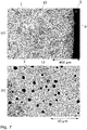
- Figs. 7 and 8 each show two SEM micrographs of a cross section of the component 1 at the interface between the glass element 5 and the base body 3.
- the base body 3 of this example is a metal injection molded stainless steel part.
- the micrographs (b) have a magnification which is 10 times higher than that of micrographs (a).
- the wall 9, or the interface to the glass element 5 is visible.
- the example of Fig. 7 has a higher porosity than the example of Fig. 8 .
- the example of Fig. 7 has a density of about 95 %, corresponding to a porosity of about 5%.
- the pores may be introduced during the PIM process, especially a MIM-process. From the cross section micrographs, an analysis of the pore sizes and pore density can be performed. To do so, the image contrast can be enhanced to black and white. For example, the area fraction of the pores may then be obtained by comparing the number of black pixels and white pixels.
- the results of the analysis for the both examples are listed in the following table: Example of Fig. 7 , 95% density Example of Fig. 8 , 98% density, 1 st area Example of Fig.
- the analysis for the example with the more dense base body was carried out at two different surface areas. As can be seen from the results, however, the magnitudes of the analyzed parameters are comparable. Both examples are within the preferred range of porosity. Without restriction to the examples of Fig. 7 and Fig. 8 , it is preferred that the average surface area of the pores as seen in a SEM micrograph of a cross section is in the range from 1 ⁇ m 2 to 20 ⁇ m 2 . Further, the density of pores as seen in a SEM micrograph of a cross section of the base body 3 is in the range from 1 to 10 pores per 1000 ⁇ m 2 .
- the glass for the glass element 5 preferably is a soda lime glass, an alumo silicate glass or a borosilicate glass.
- a stainless steel base body 3 the difference in the thermal expansion coefficient is still sufficient to produce a compressive stress acting on the glass element 5 after cooling down the component 1.
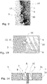
- Fig. 9 shows a further SEM micrograph of a cross section crossing the wall 9 of the opening 7, or the interface between the glass element 5 and the base body 3.
- Fig. 10 shows an idealized schematic of the surface topography of the wall 9.
- the pores 13 in the base body 3 are advantageous as these can provide an interlock between the glass and the base body if they open up at the surface of the wall 9.
- Other surface structures may provide an interlock as well.
- the SEM micrograph of Fig. 9 shows several interlocking features 15 of the wall texture.
- the wall 9 is structured or textured so as to provide at least one interlocking element, or interlocking feature 15, respectively, wherein the glass of the glass element surrounds the interlocking feature so that the glass and the base body 3 are interlocked.
- the interlocking feature 15 may comprise an undercut 16. Two undercuts 16 are marked in Fig. 9 .
- Fig. 10 shows a segment of the wall 9 with an open pore 13.
- the pore 13 widens within the base body 3 with respect to its opening 18 at the wall 9 so that there is an undercut 16 behind the opening.
- the glass of the element 5 penetrates into the pore 13 and fills up the widened part of the pore 13.
- the interlock does not only provide a blocking against a movement parallel to the wall 9, but also in a direction perpendicular to the wall 9.
- the interlocking feature 15 is formed so as to provide a locking of the glass to the base body3 in a direction perpendicular to the wall 9.
- a housing 22 for an electronic device 20 is provided, wherein the housing 22 comprises a component 1 as described herein.
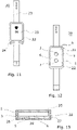
- Fig. 11 and Fig. 12 show an electronic device 20 with a housing 22 comprising the component 1 with the base body and the glass element.
- the electronic device may be a wearable device.
- the electronic device 20 is designed as a wrist-wearable item, in particular a wrist watch.
- the electronic device 20 may include a heart rate monitor.
- the electronic device 20 may comprise a bracelet 23 by means of which the electronic device 20 can be attached to the user's arm.
- the measured heart rate can be displayed on display 25 arranged on a front of the housing 22.
- the electronic device 20 may also include operating means 24 such as one or more buttons or a display 25 having touch sensitivity.
- the electronic device is designed as a so-called smart watch so that the device is able to serve for a variety of functions.
- Fig. 12 shows the opposite side of the electronic device 20 with the part of the housing 22 facing the user's wrist.
- This part of the housing 22 includes the component 1 as described herein.
- the outer surface of the component 1 is a polished face 31.
- the polished face 31 may be provided with a passivation layer 32.
- a suitable passivation layer is a layer that comprises chromium and/or oxygen.
- passivation layer 32 may comprise chromium oxide or consist of chromium oxide.
- Such a passivation layer 32 may be favorable especially for uses of the component in harsh environments and/or in application with close contact to human skin.
- the component 1 may comprise two or more glass elements 5 seated in respective openings 7.
- an electronic device 20 is provided having a housing 22 with a component 1 according to this disclosure, wherein the component 1 has two glass elements 5, 6, i.e.
- the electronic device 20 comprises a photoplethysmography sensor device.
- Photoplethysmography uses a light source and a photodetector to measure the volumetric variations of blood circulation.
- the electronic device 20 preferably comprises a light source and a light sensor.
- the light source may be a light emitting diode 28 and the light sensor may be a photodiode 29. Both diodes 28, 29 may be mounted on a printed circuit board 27 accommodated in the housing 22.
- a light emitter and a light sensor of the electronic device 20 are positioned so that light of the light emitter (such as the light emitting diode 28) is emitted through a first element 5 and light is received by the sensor (such as the photodiode 29) through a second element 6.
- This is advantageous to avoid crosstalk.
- An arrangement with a light emitter and a sensor behind separate elements 5, 6 may also be useful for other applications, e.g. distance measurements.
- the glass element 5 forms a glass window, in particular to transmit light.
- the glass element may be an insulating element of an electrical feedthrough 8.
- An embodiment of a component 1 with an electrical feedthrough is shown in Fig. 14 .
- the example of Fig. 14 is a variant of the example of Fig. 4 .
- the feedthrough 8 comprises at least one electrically conductive pin 10 being fixed within the opening 7 and electrically isolated from the base body 3 by the glass element 5.
- the pin 10 extends through the glass element so that the pin 10 can be electrically connected at both opposite sides of the glass element 5.
- one face 31 of the component 1 may be planed or polished, with flushing surfaces of the base body 3 and the glass element 5.
- the pin 10 may be planed so that the end of the pin 10 flushes with the glass surface.
Landscapes
- Chemical & Material Sciences (AREA)
- Engineering & Computer Science (AREA)
- Ceramic Engineering (AREA)
- Life Sciences & Earth Sciences (AREA)
- Chemical Kinetics & Catalysis (AREA)
- General Chemical & Material Sciences (AREA)
- Geochemistry & Mineralogy (AREA)
- Materials Engineering (AREA)
- Organic Chemistry (AREA)
- Glass Compositions (AREA)
- Joining Of Glass To Other Materials (AREA)
Abstract
Description
- The present application relates to components comprising a sealed glass element, such as a glass-to-metal-seal. In particular, the present application relates to a component comprising a base body and a glass element that may be used in a housing for further components, especially such further components that are sensitive, for example to moisture, and need to be sealed.
- Glass-to-metal seal technology is used for encapsulating sensor chips or devices which are sensitive or require water proof or dust proof enclosure. It is known to produce the metal parts by stamping or cold forging. Further, CNC machining may be used. However, CNC machining for complex features is a costly method.
- Further, metals and glass have very distinct chemical and mechanical properties so that a hermetic joint between this materials may be different to achieve or to maintain over long time spans.
- It is therefore an object of the invention to provide a component with a glass element with a base body with an improved joint between the glass and the base body. This object is solved by the subject matter of the independent claims. Advantageous refinements of the invention are defined in the dependent claims.
- Accordingly, a component with a base body and a least one glass element is provided, wherein the glass element is seated in an opening of the base body. The base body is a powder injection molded element. Due to the powder injection molding process, the wall of the opening has an uneven, rough texture. In particular, this texture is aperiodic, in contrast, e.g., to machined openings. Further, the glass of the glass element is fused into the opening and hermetically seals the opening.
- The term glass as used in this description also comprises a glass ceramic, in particular as known from other publications from the applicant. Suitable glass ceramics according to an embodiment are selected from the system MO (M=Mg, Ca)-Al2O3-BaO-SiO2-B2O3. Further, glass ceramics sold under the brand name "Heatan" may be employed.
- The combination of the characteristic surface texture of the injection molded base body and the fused glass element result in a particular firm anchoring of the glass within the opening. In particular, due to the fusing, the glass closely approximates the surface of the wall, or, in other words wets the surface of the wall so that protrusions and voids at the wall are in contact with the glass. Thus, the fusing to the rough wall and the close approximation result in a positive locking of the glass to the wall surface.
- In a preferred embodiment, the interface between the glass of the element and the base body may constitute a substance-to-substance bond, or a chemical bond, respectively, to further enhance the hermeticity of the seal. A substance-to-substance-bond is understood as a bond between materials wherein the bonding partners (base body and glass element) are joined to each other by an atomic and/or molecular force, such as adhesion. Of course, a close approximation of the glass to the wall of the base body is advantageous to promote a thorough substance-to-substance bond.
- According to a preferred embodiment, the base body is a metal injection molded part. However, it is also possible to produce the base body by ceramic injection molding. Suitable materials for a ceramic injection molded base body are ceramics containing ZrO2 and Al2O3.
- The component may be produced with a method, comprising the steps of:
- providing a powder injection molded base body with an opening, the wall of the opening having an uneven, rough texture as generated by the injection molding process,
- heating the base body and fusing a glass element to the wall of the opening, and
- cooling down the base body and the glass element to produce a glass element that hermetically seals the opening.
- Generally, the method has the additional advantage that complex designs can be easily realized by the injection molding process. However, coming along with the injection molding, the base body typically has a certain porosity which is also visible at its surface. In this regard it is surprising that not only the base part itself but also the interface to the glass element proves to be hermetically sealed.
- In the following, the invention is described in more detail with reference to the accompanying drawings.
-
-
Fig. 1 shows a cross section of a base body. -
Fig. 2 shows the base body with a glass element before fusing the glass element into an opening of the base body. -
Fig. 3 shows a component with a base body and a glass element, -
Fig. 4 shows the component after a finishing step. -
Fig. 5 shows element concentrations of iron and chromium along a line crossing the interface between the base body and the glass element. -
Fig. 6 shows element concentrations of iron and chromium along a line within the glass element. -
Figs. 7 and8 each show two SEM micrographs of a cross section of a component, wherein the base body of the example ofFig. 7 has a higher porosity than the base body of the example ofFig. 8 . -
Fig. 9 shows a further SEM micrograph of a cross section at the wall of the opening. -
Fig. 10 shows a schematic of a section of the interface region between the base body and the glass element. -
Fig. 11 and Fig. 12 show an electronic device with a housing comprising the component with the base body and the glass element. -
Fig. 13 shows a cross section of an electronic device. -
Fig. 14 shows an embodiment where the glass element forms an insulating element of an electrical feedthrough. - With reference to
Figs. 1 to 4 , method steps for producing acomponent 1 with abase body 3 and aglass element 5 according to this disclosure are specified. Abase body 3 is provided, which is produced by powder injection molding. Preferably, the powder injection molding is a metal injection molding (MIM) process. As well, a ceramic injection molded part may be used as the base body. For example, the base body may be a ZrO2- or Al2O3-ceramics. Typical method steps for producing a powder injection molded body include forming a raw body from powder (in particular metal or ceramic powder) and a binder, debinding the raw body to obtain a green body and then sintering the green body to obtain thebase body 3. Debinding, i.e. partial removal of the binder may include one or more of removing the binder by solvents, thermal or catalytic processes. - An illustrative example of a
base body 3 is shown inFig. 1 . Thebase body 3 has anopening 7 which serves to accommodate a glass element. Theouter surface 30 of thebase body 3 as well as thewall 9 of theopening 7 have a certain surface roughness, represented inFig 1 by a slightly meandering outline. This roughness is caused by the powder injection molding process which involves sintering of particles (i.e. metal particles in a metal injection molding process or ceramic or oxide particles in a ceramic injection molding process). The surface roughness inter alia depends on the grain size of the powder used for producing thebase body 3. Preferably, the surface roughness Ra of the wall is within a range of from 1 µm to 5 µm. For example, the surface roughness Ra may have a value of about 3 µm. These roughness values may be measured using sampling lengths in the range of between 1 mm and 3 mm. Thus, generally, the surface of thebase body 3 as provided for the subsequent process steps for producing a component with a glass element has an uneven, rough texture. Further, in difference to typical CNC manufactures parts, the texture has random and, therefore, aperiodic surface features. As shown inFig. 2 , aglass element 4 may be inserted into theopening 7. Then, thebase body 3 is heated together with theglass element 4 so that theglass element 4 melts and fuses to thewall 9 of theopening 7. Then, the base body3 and theglass element 4 are cooled down to produce aglass element 5 that hermetically seals theopening 7. Thecomponent 1 derived thereby is shown inFig. 3 . During the sealing process, the glass flows into theuneven wall 9 and voids therein to form additional mechanical interlock or serration, in analogy to a hook-and-loop fastener. According to one embodiment, the composition of the glass may be selected to form a glass ceramic. In this case, ceramization may be initiated during the fusing process so that the glass element is formed from a glass ceramic after cooling down. - The cooling process may be active or passive. According to an embodiment, the
glass element 5 is compressively sealed within theopening 7. In other words, after cooling down themetal body 3 exerts a compressive stress to theelement 5. This feature can be achieved if themetal body 3 has a higher shrinkage than the glass element during the cooling process. This higher shrinkage may be achieved by selection of the materials, so that themetal body 3 has a higher linear thermal expansion coefficient αMetal compared to the linear thermal expansion coefficient αGlass of theglass element 5. This condition does not need to be met over the whole temperature range of the cooling process. However, a compressive seal in particular can be achieved if αMetal is larger than αGlass in a temperature range below the glass transition temperature Tg of the glass and room temperature (20 °C). - For this embodiment, the material of the
base body 3 and the glass are selected so that the linear thermal expansion coefficient of the base body at 20 °C is larger than the linear thermal expansion coefficient of the glass by at least 2 ppm, preferably by at least 5 ppm. - Alternatively or in addition to the compressive seal, the glass of the
glass element 5 and the metal ofmetal part 3 may be chemically bonded together, to provide a particularly robust and hermetical seal. - Further, it is as well possible to use materials for the
base body 3 and the glass element having largely matching thermal expansion coefficient. Due to the rough wall texture and the serration of the glass with the wall of the base body, a firm anchoring of the glass element in theopening 7 is ensured even without a compression seal. -
Fig. 4 shows thecomponent 1 after a preferred post-processing step. As can be seen, oneface 31 of thecomponent 1 is planed or polished, with flushing surfaces of thebase body 3 and theglass element 5. Specifically, flushing surfaces are understood as having a height difference or step height at the interface that is 1 µm at most. By the polishing, the roughness of thisface 31 is reduced with respect to the roughness of the opposite side or thewall 9 of theopening 7. The processedsurface 31 of thebase body 3 is preferably at least partially covered with a passivation layer. - Generally, according to an advantageous refinement, the
metal part 3 may at least at thewall 9 of the opening be covered with an oxide layer. This oxide layer can promote a substance-to-substance bond, or chemical bond, respectively. This is of particular advantage for a matched seal of the glass element to the base body, i.e. in the case that there is no substantial compression acting on the glass element. Theoxide layer 11 covering thewall 9 of theopening 7 is shown inFigs. 1 and 2 . Accordingly, the interface between the glass of theglass element 5 and thewall 9 of theopening 7 in thebase body 3 preferably includes anoxide layer 11. As will be further specified below, theoxide layer 11 may constitute a diffusion zone, wherein at least one constituent of the glass or the base body is diffused into the oxide layer. This diffusion can effect a strong chemical bond. Thus, by means of thismetal oxide layer 11, a chemical bond can be formed through ions diffusion from the base body to glass and vice versa. - According to a further preferred embodiment, the
base body 3 contains chromium. In particular, thebase body 3 may be formed from stainless steel, which typically contains chromium. Preferably, an austenitic steel is chosen. - Chromium has the ability to form a dense and
stable oxide layer 11, which, as explained above, can provide a chemical bond between the glass and the metal and/or may constitute a diffusion zone. Thus, according to a further embodiment, thewall 9 of theopening 7 of thebase body 3 is covered with a chromium oxide containing layer. However, an optional oxide layer may not be the only part of a diffusion zone. Rather, according to a further embodiment, at least one constituent of thebase body 3 may diffuse into the glass and/or vice versa. Thus, a diffusion zone at the glass-metal-interface may be established with at least one of the following features: - at least one constituent of the
base body 3 is diffused into the glass - at least one constituent of the glass is diffused into the
base body 3. - As described, other steel types such as AISI 430 are also possible as well as other alloys and/or metals, such as titanium. Besides of steel, further suitable materials for the
base body 3 are nickel/iron alloys, such as Kovar. It is again preferred that thebase body 3 is covered with a metal oxide layer. For a Ni/Fe alloy, ametal oxide layer 11 may be produced by an oxidation step. Generally, without restriction to particular metals of thebase body 3, anoxide layer 11 may also be provided by a deposition process, preferably by CVD or PVD -
Fig. 5 shows element concentrations of iron and chromium along a line crossing the interface between thebase body 3 and theglass element 5. The measurements were performed using EDX. Thebase body 3 is formed from stainless steel of type 316 L and thus contains iron and chromium. The measuringpositions 1 to 11 are distributed along a line vertically to theinterface 35 between thebase body 3 and theglass element 5. The distance between the first and last measuring position is 6 µm. The upper graph shows the variation in the iron concentration and the lower graph is the variation of the chromium content. As can be seen from the graphs, there is a depletion of both iron and chromium within the metal part in a region adjacent to the interface. Likewise, both Fe and Cr are diffused into the glass in a region of theglass element 5 close tointerface 35. This migration of metal ions from thebase body 3 into the glass element strengthens the chemical bond between bothparts - Thus, according to an embodiment of the
component 1, at least one of the following features is present at the interface 35: - the
base body 3 contains iron and there is a depletion of the iron content of the base body in a region adjacent to theinterface 35 between thebase body 3 and the glass element, whereas the glass element has an increased iron content in a region adjacent to theinterface 35, - the
base body 3 contains chromium and there is a depletion of the chromium content of the base body in a region adjacent to theinterface 35 between thebase body 3 and the glass element, whereas the glass element has an increased chromium content in a region adjacent to theinterface 35. - Further, as can be seen from the graphs of
Fig. 5 , - the thickness of the region of iron depletion in the
base body 3 is at least 0.5 µm, and - the thickness of the region of chromium depletion in the
base body 3 is at least 2 µm. -
Fig. 6 shows element concentrations along a line within the glass element. As forFig. 5 , the line extends vertically to theinterface 35. The measurement points are considerably wider apart compared toFig. 5 . Specifically, the distance between the first and the last measurement point is about 150 µm. As can be estimated fromFig. 6 , the thickness of the region adjacent to theinterface 35 where the iron content is increased due to diffusion from thebase body 3 is at least 75 µm. The same holds for the thickness of the region with increased chromium content. - According to a further embodiment, constituents of the glass which may diffuse into the
base body 3 are alkaline ions, particularly Na+ and K+, depending on the glass composition. - It is very advantageous and generally preferred, that the
base body 3 is porous. In particular if the pores are randomly distributed within the base body, the formation of leak paths is even less likely than, e.g. for drawn metals. In the case of drawn metal parts, a defect within the metal may be elongated in the drawing process and thereby forming a leak path. However, a porosity of the base body which is too high may nevertheless result in leak paths through thebase body 3 or eventually to mechanical flaws. For this reason, it is preferred that the porosity, i.e. the volume fraction of pores in thebase body 3 is less than 6%. Vice versa, it is preferred that the density of thebase body 3 amounts to at least 93% of the maximum theoretical density. On the other hand, the pores are very advantageous for the texture of thewall 9 which result in the improved anchoring of theglass element 5 within theopening 7. It is therefore further preferred that the porosity, i.e. the volume fraction of pores in thebase body 3 amounts to at least 1.5 %. - In the following, two examples of
components 1 withbase body 3 having different porosity are discussed. -
Figs. 7 and8 each show two SEM micrographs of a cross section of thecomponent 1 at the interface between theglass element 5 and thebase body 3. Thebase body 3 of this example is a metal injection molded stainless steel part. As can be seen from the scale bars, the micrographs (b) have a magnification which is 10 times higher than that of micrographs (a). In the micrographs (a), thewall 9, or the interface to theglass element 5 is visible. It is clearly visible that the example ofFig. 7 has a higher porosity than the example ofFig. 8 . Specifically, the example ofFig. 7 has a density of about 95 %, corresponding to a porosity of about 5%. The example ofFig. 8 has a density of 98%, or a porosity of about 2%, respectively. Porosity Φ is in the scope of the present disclosure considered to be the ratio of the sum of the volumes of thepores 13, Vp, relative to the volume ofbase body 3,Vmb (including the pore volume):
- Generally, the pores may be introduced during the PIM process, especially a MIM-process. From the cross section micrographs, an analysis of the pore sizes and pore density can be performed. To do so, the image contrast can be enhanced to black and white. For example, the area fraction of the pores may then be obtained by comparing the number of black pixels and white pixels. The results of the analysis for the both examples are listed in the following table:
Example of Fig. 7 , 95% densityExample of Fig. 8 , 98% density, 1st areaExample of Fig. 8 , 98% density, 2nd areaOverall percentage of pore area 4.899 % 0.258 % 0.324% Average surface area of pore 11.614 µm2 1.606 µm2 2.080 µm2 Largest pore surface area 170.653 µm2 135.688 µm2 411.161 µm2 Smallest pore surface area 0.671 µm2 0.512 µm2 0.512 µm2 Pores found 3151 859 778 Pore density (pores per 1000µm2) 5.7 1.63 1.55 - The analysis for the example with the more dense base body was carried out at two different surface areas. As can be seen from the results, however, the magnitudes of the analyzed parameters are comparable. Both examples are within the preferred range of porosity. Without restriction to the examples of
Fig. 7 andFig. 8 , it is preferred that the average surface area of the pores as seen in a SEM micrograph of a cross section is in the range from 1 µm2 to 20 µm2. Further, the density of pores as seen in a SEM micrograph of a cross section of thebase body 3 is in the range from 1 to 10 pores per 1000 µm2. - Generally, without restriction to the examples, the glass for the
glass element 5 preferably is a soda lime glass, an alumo silicate glass or a borosilicate glass. The glass used for theglass element 5 of the above discussed examples is a soda lime glass with a linear thermal expansion coefficient α(20°C;300°C) = 9.1·10-6/K which is comparably high. However, using a stainlesssteel base body 3, the difference in the thermal expansion coefficient is still sufficient to produce a compressive stress acting on theglass element 5 after cooling down thecomponent 1. -
Fig. 9 shows a further SEM micrograph of a cross section crossing thewall 9 of theopening 7, or the interface between theglass element 5 and thebase body 3. To further illustrate the features of the wall texture,Fig. 10 shows an idealized schematic of the surface topography of thewall 9. Thepores 13 in thebase body 3 are advantageous as these can provide an interlock between the glass and the base body if they open up at the surface of thewall 9. Other surface structures may provide an interlock as well. The SEM micrograph ofFig. 9 shows several interlocking features 15 of the wall texture. Thus, according to an embodiment, which is not restricted to the depicted example, thewall 9 is structured or textured so as to provide at least one interlocking element, or interlockingfeature 15, respectively, wherein the glass of the glass element surrounds the interlocking feature so that the glass and thebase body 3 are interlocked. In particular, the interlockingfeature 15 may comprise an undercut 16. Two undercuts 16 are marked inFig. 9 . -
Fig. 10 shows a segment of thewall 9 with anopen pore 13. As can be seen, thepore 13 widens within thebase body 3 with respect to itsopening 18 at thewall 9 so that there is an undercut 16 behind the opening. The glass of theelement 5 penetrates into thepore 13 and fills up the widened part of thepore 13. This way, the interlock does not only provide a blocking against a movement parallel to thewall 9, but also in a direction perpendicular to thewall 9. Of course, there may be other features of the surface texture caused by the powder injection process that provide similar locking qualities. Thus, according to an advantageous refinement, the interlockingfeature 15 is formed so as to provide a locking of the glass to the base body3 in a direction perpendicular to thewall 9. - There is a variety of applications for a
component 1 as described herein. According to a particular preferred embodiment, ahousing 22 for anelectronic device 20 is provided, wherein thehousing 22 comprises acomponent 1 as described herein.Fig. 11 and Fig. 12 show anelectronic device 20 with ahousing 22 comprising thecomponent 1 with the base body and the glass element. Specifically, as shown, the electronic device may be a wearable device. Preferably, theelectronic device 20 is designed as a wrist-wearable item, in particular a wrist watch. According to a further refinement, theelectronic device 20 may include a heart rate monitor. - As shown in
Figs. 11, 12 , theelectronic device 20 may comprise abracelet 23 by means of which theelectronic device 20 can be attached to the user's arm. The measured heart rate can be displayed ondisplay 25 arranged on a front of thehousing 22. Further, theelectronic device 20 may also include operating means 24 such as one or more buttons or adisplay 25 having touch sensitivity. Preferably, the electronic device is designed as a so-called smart watch so that the device is able to serve for a variety of functions. -
Fig. 12 shows the opposite side of theelectronic device 20 with the part of thehousing 22 facing the user's wrist. This part of thehousing 22 includes thecomponent 1 as described herein. Preferably, the outer surface of thecomponent 1 is apolished face 31. Generally, without being limited to the embodiment shown here, thepolished face 31 may be provided with a passivation layer 32. A suitable passivation layer is a layer that comprises chromium and/or oxygen. For example, passivation layer 32 may comprise chromium oxide or consist of chromium oxide. Such a passivation layer 32 may be favorable especially for uses of the component in harsh environments and/or in application with close contact to human skin. For example, even though steel is a corrosion resistant material, upon contact with human skin a certain degree of surface degradation may nonetheless take place, resulting, for example, in a leaching out of certain substances. For example, nickel may be leached out of thebase body 3, causing allergic reactions. - In the examples described above, a
single element 5 is shown. However, generally, thecomponent 1 may comprise two ormore glass elements 5 seated inrespective openings 7. Thus, according to a refinement which is also realized in the example ofFigs. 11, 12 , anelectronic device 20 is provided having ahousing 22 with acomponent 1 according to this disclosure, wherein thecomponent 1 has twoglass elements component 1 with ametal body 3 and twoglass elements glass elements opening 7 of thebase body 3, wherein thebase body 3 is a powder injection molded, in particular a metal injection molded element so that thewalls 9 of theopenings 7 have an uneven, rough texture, and wherein the glass of theglass element 5 is fused into theopening 7 so that the glass closely approximates the surface of thewall 9 and hermetically seals theopening 7. - According to a further embodiment, the
electronic device 20 comprises a photoplethysmography sensor device. This embodiment is explained in more detail with respect to the example ofFig. 13 . Photoplethysmography (PPG) uses a light source and a photodetector to measure the volumetric variations of blood circulation. Thus, theelectronic device 20 preferably comprises a light source and a light sensor. The light source may be alight emitting diode 28 and the light sensor may be aphotodiode 29. Bothdiodes circuit board 27 accommodated in thehousing 22. Further, generally and independent from the embodiment of a photoplethysmography sensor device, a light emitter and a light sensor of theelectronic device 20 are positioned so that light of the light emitter (such as the light emitting diode 28) is emitted through afirst element 5 and light is received by the sensor (such as the photodiode 29) through asecond element 6. This is advantageous to avoid crosstalk. An arrangement with a light emitter and a sensor behindseparate elements - For many applications and without restriction to the examples shown in the figures, the
glass element 5 forms a glass window, in particular to transmit light. For example, this may be the case for the wearable device ofFig 11 or the electronic device shown inFig. 13 . According to a further, alternative or additional embodiment, the glass element may be an insulating element of anelectrical feedthrough 8. An embodiment of acomponent 1 with an electrical feedthrough is shown inFig. 14 . The example ofFig. 14 is a variant of the example ofFig. 4 . Generally, without restriction to the example, thefeedthrough 8 comprises at least one electricallyconductive pin 10 being fixed within theopening 7 and electrically isolated from thebase body 3 by theglass element 5. Thepin 10 extends through the glass element so that thepin 10 can be electrically connected at both opposite sides of theglass element 5. As in the embodiment ofFig. 4 and as shown inFig. 14 , oneface 31 of thecomponent 1 may be planed or polished, with flushing surfaces of thebase body 3 and theglass element 5. In this case, also thepin 10 may be planed so that the end of thepin 10 flushes with the glass surface.List of reference signs 1 Component 3 Base body 4 Glass element 5, 6 Glass element 7 Opening 8 Electrical feedthrough 9 Wall of opening 710 Pin 11 Oxide layer 13 Pore 15 Interlocking feature 16 Undercut 18 Opening of pore 1320 Electronic device 22 Housing of 20 23 Bracelet 24 Operating means 25 Display 27 PCB = Printed Circuit Board 28 Light emitting diode 29 Photodiode 30 Outer surface of metal body 331 Polished face of component 132 Passivation layer 35 Interface between base body 3 andglass element 5
Claims (15)
- A component (1) with a base body (3) and a glass element (5), the glass element (5) being seated in an opening (7) of the base body (3), wherein the base body (3) is a powder injection molded element so that the wall (9) of the opening (7) has an uneven, rough texture, and wherein the glass of the glass element (5) is fused into the opening (7) so that the glass closely approximates the surface of the wall (9) and hermetically seals the opening. (7).
- The component (1) according to the preceding claim, wherein the surface roughness Ra of the wall (9) is within a range of from 1 µm to 5 µm.
- The component (1) according to one of the preceding claims, characterized by at least one of the following features:- the base body is a metal injection molded part or a ceramic injection molded part,- the base body (3) is porous.
- The component (1) according to the preceding claim, characterized by at least one of the following features:- the volume fraction of pores (13) in the base body (3) is less than 6%,- the volume fraction of pores (13) in the base body (3) is at least 1.5 %,- the average surface area of the pores (13) as seen in a cross section is in the range from 1 µm2 to 20 µm2,- the density of pores (13) as seen in cross section of the base body (3) is in the range from 1 to 10 pores per 1000 µm2.
- The component (1) according to one of the preceding claims, characterized by at least one of the following features:- the glass element (5) is compressively sealed within the opening (7),- the glass of the glass element (5) is a soda lime glass or a borosilicate glass,- the base body (3) has a higher linear thermal expansion coefficient αMetal compared to the linear thermal expansion coefficient αGlass of the glass element (5),- the glass of the glass element (5) and base body (3) are chemically bonded together,- the glass element (5) forms a window- the component (1) has an electrical feedthrough (8), with the glass element (5) forming an insulating element for at least one electrically conductive pin (10).
- The component (1) according to one of the preceding claims, wherein the interface between the glass of the glass element (5) and the wall (9) of the opening (7) in the base body (3) includes an oxide layer (11).
- The component according to the preceding claim, wherein the oxide layer (11) constitutes a diffusion zone, wherein at least one constituent of the glass or the base body (3) is diffused into the oxide layer (11).
- The component (1) according to one of the preceding claims, characterized by a diffusion zone at the glass-metal-interface with at least one of the following features:- at least one constituent of the base body (3) is diffused into the glass- at least one constituent of the glass is diffused into the base body (3).
- The component according to one of the preceding claims, characterized by at least one of the following features:- the base body (3) contains chromium,- the base body (3) is formed from stainless steel,- the wall (9) of the opening (7) of the base body (3) is covered with a chromium oxide containing layer (11).
- The component according to one of the preceding claims, wherein the wall (9) is textured so as to provide at least one interlocking feature (15), wherein the glass of the glass element (5) surrounds the interlocking feature (15) so that the glass and the metal of the base body (3) are interlocked.
- The component according to one of the preceding claims, wherein one face (31) of the component (1) being polished, with flushing surfaces of the base body (3) and the glass element (5).
- A method of producing a component (1) according to one of the preceding claims, comprising the steps of- providing a powder injection molded base body (3) with an opening (7), the wall (9) of the opening (7) having an uneven, rough texture as generated by the injection molding process,- heating the base body (3) and fusing a glass element (4) to the wall (9) of the opening (7), and- cooling down the base body (3) and the glass element to produce a glass element (5) that hermetically seals the opening (7).
- The method according to the preceding claim, wherein the base body (3) has a higher shrinkage than the glass element (5) during the cooling process so that the base body (3) exerts a compressive stress to the element (5) after cooling down.
- An electronic device (20) with a housing (22), wherein the housing (22) comprises a component (1) according to one of claims 1 to 12 or produced using a method according to one of claims 13, 14.
- The electronic device according to the preceding claims, having at least one of the following features:- the electronic device (20) is a wearable device,- the electronic device (20) comprises a photoplethysmography sensor device,- the component (1) has two glass elements (5, 6)- a light emitter and a light sensor of the electronic device 20 are positioned so that light of the light emitter is emitted through a first element (5) and light is received by the sensor through a second element.
Priority Applications (2)
| Application Number | Priority Date | Filing Date | Title |
|---|---|---|---|
| EP20198143.8A EP3974399B1 (en) | 2020-09-24 | 2020-09-24 | Component with a glass element and method for producing the same |
| CN202022709131.0U CN216808623U (en) | 2020-09-24 | 2020-11-20 | Component for encapsulation with base body and glass element and electronic device with housing |
Applications Claiming Priority (1)
| Application Number | Priority Date | Filing Date | Title |
|---|---|---|---|
| EP20198143.8A EP3974399B1 (en) | 2020-09-24 | 2020-09-24 | Component with a glass element and method for producing the same |
Publications (2)
| Publication Number | Publication Date |
|---|---|
| EP3974399A1 true EP3974399A1 (en) | 2022-03-30 |
| EP3974399B1 EP3974399B1 (en) | 2023-09-06 |
Family
ID=72659018
Family Applications (1)
| Application Number | Title | Priority Date | Filing Date |
|---|---|---|---|
| EP20198143.8A Active EP3974399B1 (en) | 2020-09-24 | 2020-09-24 | Component with a glass element and method for producing the same |
Country Status (2)
| Country | Link |
|---|---|
| EP (1) | EP3974399B1 (en) |
| CN (1) | CN216808623U (en) |
Citations (3)
| Publication number | Priority date | Publication date | Assignee | Title |
|---|---|---|---|---|
| US4921738A (en) * | 1988-12-09 | 1990-05-01 | The United States Of America As Represented By The United States Department Of Energy | Li2 O-Al2 O3 -SiO2 glass ceramic-aluminum containing austenitic stainless steel composite body and a method of producing the same |
| US20160268791A1 (en) * | 2015-03-12 | 2016-09-15 | Schott Ag | Matched seal feedthrough |
| US20190112225A1 (en) * | 2016-06-21 | 2019-04-18 | Scott Ag | Bond produced with an at least partially crystallized glass, such as a metal-to-glass bond, in particular a metal-to-glass bond in a feed-through element or connecting element, and method for producing such a bond, in particular in a feed-through element or connecting element |
-
2020
- 2020-09-24 EP EP20198143.8A patent/EP3974399B1/en active Active
- 2020-11-20 CN CN202022709131.0U patent/CN216808623U/en active Active
Patent Citations (3)
| Publication number | Priority date | Publication date | Assignee | Title |
|---|---|---|---|---|
| US4921738A (en) * | 1988-12-09 | 1990-05-01 | The United States Of America As Represented By The United States Department Of Energy | Li2 O-Al2 O3 -SiO2 glass ceramic-aluminum containing austenitic stainless steel composite body and a method of producing the same |
| US20160268791A1 (en) * | 2015-03-12 | 2016-09-15 | Schott Ag | Matched seal feedthrough |
| US20190112225A1 (en) * | 2016-06-21 | 2019-04-18 | Scott Ag | Bond produced with an at least partially crystallized glass, such as a metal-to-glass bond, in particular a metal-to-glass bond in a feed-through element or connecting element, and method for producing such a bond, in particular in a feed-through element or connecting element |
Non-Patent Citations (1)
| Title |
|---|
| CHOU Y S ET AL: "Effect of aluminizing of Cr-containing ferritic alloys on the seal strength of a novel high-temperature solid oxide fuel cell sealing glass", JOURNAL OF POWER SOURCES, ELSEVIER SA, CH, vol. 185, no. 2, 1 December 2008 (2008-12-01), pages 1001 - 1008, XP025672734, ISSN: 0378-7753, [retrieved on 20080907], DOI: 10.1016/J.JPOWSOUR.2008.09.004 * |
Also Published As
| Publication number | Publication date |
|---|---|
| EP3974399B1 (en) | 2023-09-06 |
| CN216808623U (en) | 2022-06-24 |
Similar Documents
| Publication | Publication Date | Title |
|---|---|---|
| US8043454B1 (en) | Method of forming hermetic vias utilizing metal-metal oxides | |
| US4912838A (en) | Method of manufacturing electrode for electromagnetic flowmeter | |
| US5050034A (en) | Pressure sensor and method of manufacturing same | |
| US7758970B2 (en) | Different materials bonded member and production method thereof | |
| US8763245B1 (en) | Hermetic feedthrough assembly for ceramic body | |
| EP1017104A3 (en) | Ferroelectric intergrated circuit with protective layer incorporating oxygen and method for fabricating same | |
| EP3974399B1 (en) | Component with a glass element and method for producing the same | |
| CN1327304C (en) | Zirconium oxide matrix product, method for obtaining same and use thereof | |
| US6764773B2 (en) | Heat-dissipating substrate, method for making the same, and semiconductor device including the same | |
| CA2127685A1 (en) | Silver-metal oxide materials for electrical contacts | |
| Feller et al. | Ceramic multilayer technology as a platform for miniaturized sensor arrays for water analysis | |
| EP3974400B1 (en) | Component comprising a glass element and a base body, method for producing such and its use | |
| Dittmer et al. | Advanced CerMet ceramic composites for medical applications | |
| WO2023063396A1 (en) | Joined body, housing for electronic components, diaphragm support, and method for producing joined body | |
| JP4014250B2 (en) | Carbon dioxide sensor | |
| Schilm et al. | Joining technologies for a temperature-stable integration of a LTCC-based pressure sensor | |
| KR101799645B1 (en) | Lid for gas-tight seal and manufacturing method of the same, electronic component receiving package using the same | |
| JP2610050B2 (en) | Quartz glass tube for semiconductor heat treatment | |
| JP2005091253A (en) | Concentration cell type oxygen sensor and manufacturing method thereof | |
| US11964909B2 (en) | Sealing glass and use thereof | |
| CN1016727B (en) | Method for manufacturing electromagnetic flowmeter electrodes | |
| EP3929170B1 (en) | Sintering process for electrical feedthroughs | |
| US7324330B2 (en) | Capacitor element for solid electrolytic capacitor and method of making the same | |
| AU600190B2 (en) | Method of manufacturing electrode for electromagnetic flowmeter | |
| SU755771A1 (en) | METHOD OF CONNECTING CERAMIC DETAILS WITH METAL |
Legal Events
| Date | Code | Title | Description |
|---|---|---|---|
| STAA | Information on the status of an ep patent application or granted ep patent |
Free format text: STATUS: EXAMINATION IS IN PROGRESS |
|
| PUAI | Public reference made under article 153(3) epc to a published international application that has entered the european phase |
Free format text: ORIGINAL CODE: 0009012 |
|
| 17P | Request for examination filed |
Effective date: 20201023 |
|
| AK | Designated contracting states |
Kind code of ref document: A1 Designated state(s): AL AT BE BG CH CY CZ DE DK EE ES FI FR GB GR HR HU IE IS IT LI LT LU LV MC MK MT NL NO PL PT RO RS SE SI SK SM TR |
|
| RBV | Designated contracting states (corrected) |
Designated state(s): AL AT BE BG CH CY CZ DE DK EE ES FI FR GB GR HR HU IE IS IT LI LT LU LV MC MK MT NL NO PL PT RO RS SE SI SK SM TR |
|
| GRAP | Despatch of communication of intention to grant a patent |
Free format text: ORIGINAL CODE: EPIDOSNIGR1 |
|
| STAA | Information on the status of an ep patent application or granted ep patent |
Free format text: STATUS: GRANT OF PATENT IS INTENDED |
|
| INTG | Intention to grant announced |
Effective date: 20230524 |
|
| P01 | Opt-out of the competence of the unified patent court (upc) registered |
Effective date: 20230516 |
|
| GRAS | Grant fee paid |
Free format text: ORIGINAL CODE: EPIDOSNIGR3 |
|
| GRAA | (expected) grant |
Free format text: ORIGINAL CODE: 0009210 |
|
| STAA | Information on the status of an ep patent application or granted ep patent |
Free format text: STATUS: THE PATENT HAS BEEN GRANTED |
|
| AK | Designated contracting states |
Kind code of ref document: B1 Designated state(s): AL AT BE BG CH CY CZ DE DK EE ES FI FR GB GR HR HU IE IS IT LI LT LU LV MC MK MT NL NO PL PT RO RS SE SI SK SM TR |
|
| REG | Reference to a national code |
Ref country code: GB Ref legal event code: FG4D |
|
| REG | Reference to a national code |
Ref country code: CH Ref legal event code: EP |
|
| REG | Reference to a national code |
Ref country code: IE Ref legal event code: FG4D |
|
| REG | Reference to a national code |
Ref country code: DE Ref legal event code: R096 Ref document number: 602020017108 Country of ref document: DE |
|
| REG | Reference to a national code |
Ref country code: LT Ref legal event code: MG9D |
|
| REG | Reference to a national code |
Ref country code: NL Ref legal event code: MP Effective date: 20230906 |
|
| PG25 | Lapsed in a contracting state [announced via postgrant information from national office to epo] |
Ref country code: GR Free format text: LAPSE BECAUSE OF FAILURE TO SUBMIT A TRANSLATION OF THE DESCRIPTION OR TO PAY THE FEE WITHIN THE PRESCRIBED TIME-LIMIT Effective date: 20231207 |
|
| PG25 | Lapsed in a contracting state [announced via postgrant information from national office to epo] |
Ref country code: SE Free format text: LAPSE BECAUSE OF FAILURE TO SUBMIT A TRANSLATION OF THE DESCRIPTION OR TO PAY THE FEE WITHIN THE PRESCRIBED TIME-LIMIT Effective date: 20230906 Ref country code: RS Free format text: LAPSE BECAUSE OF FAILURE TO SUBMIT A TRANSLATION OF THE DESCRIPTION OR TO PAY THE FEE WITHIN THE PRESCRIBED TIME-LIMIT Effective date: 20230906 Ref country code: NO Free format text: LAPSE BECAUSE OF FAILURE TO SUBMIT A TRANSLATION OF THE DESCRIPTION OR TO PAY THE FEE WITHIN THE PRESCRIBED TIME-LIMIT Effective date: 20231206 Ref country code: LV Free format text: LAPSE BECAUSE OF FAILURE TO SUBMIT A TRANSLATION OF THE DESCRIPTION OR TO PAY THE FEE WITHIN THE PRESCRIBED TIME-LIMIT Effective date: 20230906 Ref country code: LT Free format text: LAPSE BECAUSE OF FAILURE TO SUBMIT A TRANSLATION OF THE DESCRIPTION OR TO PAY THE FEE WITHIN THE PRESCRIBED TIME-LIMIT Effective date: 20230906 Ref country code: HR Free format text: LAPSE BECAUSE OF FAILURE TO SUBMIT A TRANSLATION OF THE DESCRIPTION OR TO PAY THE FEE WITHIN THE PRESCRIBED TIME-LIMIT Effective date: 20230906 Ref country code: GR Free format text: LAPSE BECAUSE OF FAILURE TO SUBMIT A TRANSLATION OF THE DESCRIPTION OR TO PAY THE FEE WITHIN THE PRESCRIBED TIME-LIMIT Effective date: 20231207 Ref country code: FI Free format text: LAPSE BECAUSE OF FAILURE TO SUBMIT A TRANSLATION OF THE DESCRIPTION OR TO PAY THE FEE WITHIN THE PRESCRIBED TIME-LIMIT Effective date: 20230906 |
|
| REG | Reference to a national code |
Ref country code: AT Ref legal event code: MK05 Ref document number: 1608382 Country of ref document: AT Kind code of ref document: T Effective date: 20230906 |
|
| PG25 | Lapsed in a contracting state [announced via postgrant information from national office to epo] |
Ref country code: NL Free format text: LAPSE BECAUSE OF FAILURE TO SUBMIT A TRANSLATION OF THE DESCRIPTION OR TO PAY THE FEE WITHIN THE PRESCRIBED TIME-LIMIT Effective date: 20230906 |
|
| PG25 | Lapsed in a contracting state [announced via postgrant information from national office to epo] |
Ref country code: IS Free format text: LAPSE BECAUSE OF FAILURE TO SUBMIT A TRANSLATION OF THE DESCRIPTION OR TO PAY THE FEE WITHIN THE PRESCRIBED TIME-LIMIT Effective date: 20240106 |
|
| PG25 | Lapsed in a contracting state [announced via postgrant information from national office to epo] |
Ref country code: AT Free format text: LAPSE BECAUSE OF FAILURE TO SUBMIT A TRANSLATION OF THE DESCRIPTION OR TO PAY THE FEE WITHIN THE PRESCRIBED TIME-LIMIT Effective date: 20230906 |
|
| PG25 | Lapsed in a contracting state [announced via postgrant information from national office to epo] |
Ref country code: ES Free format text: LAPSE BECAUSE OF FAILURE TO SUBMIT A TRANSLATION OF THE DESCRIPTION OR TO PAY THE FEE WITHIN THE PRESCRIBED TIME-LIMIT Effective date: 20230906 |
|
| PG25 | Lapsed in a contracting state [announced via postgrant information from national office to epo] |
Ref country code: SM Free format text: LAPSE BECAUSE OF FAILURE TO SUBMIT A TRANSLATION OF THE DESCRIPTION OR TO PAY THE FEE WITHIN THE PRESCRIBED TIME-LIMIT Effective date: 20230906 Ref country code: RO Free format text: LAPSE BECAUSE OF FAILURE TO SUBMIT A TRANSLATION OF THE DESCRIPTION OR TO PAY THE FEE WITHIN THE PRESCRIBED TIME-LIMIT Effective date: 20230906 Ref country code: IS Free format text: LAPSE BECAUSE OF FAILURE TO SUBMIT A TRANSLATION OF THE DESCRIPTION OR TO PAY THE FEE WITHIN THE PRESCRIBED TIME-LIMIT Effective date: 20240106 Ref country code: ES Free format text: LAPSE BECAUSE OF FAILURE TO SUBMIT A TRANSLATION OF THE DESCRIPTION OR TO PAY THE FEE WITHIN THE PRESCRIBED TIME-LIMIT Effective date: 20230906 Ref country code: EE Free format text: LAPSE BECAUSE OF FAILURE TO SUBMIT A TRANSLATION OF THE DESCRIPTION OR TO PAY THE FEE WITHIN THE PRESCRIBED TIME-LIMIT Effective date: 20230906 Ref country code: CZ Free format text: LAPSE BECAUSE OF FAILURE TO SUBMIT A TRANSLATION OF THE DESCRIPTION OR TO PAY THE FEE WITHIN THE PRESCRIBED TIME-LIMIT Effective date: 20230906 Ref country code: AT Free format text: LAPSE BECAUSE OF FAILURE TO SUBMIT A TRANSLATION OF THE DESCRIPTION OR TO PAY THE FEE WITHIN THE PRESCRIBED TIME-LIMIT Effective date: 20230906 Ref country code: SK Free format text: LAPSE BECAUSE OF FAILURE TO SUBMIT A TRANSLATION OF THE DESCRIPTION OR TO PAY THE FEE WITHIN THE PRESCRIBED TIME-LIMIT Effective date: 20230906 Ref country code: PT Free format text: LAPSE BECAUSE OF FAILURE TO SUBMIT A TRANSLATION OF THE DESCRIPTION OR TO PAY THE FEE WITHIN THE PRESCRIBED TIME-LIMIT Effective date: 20240108 |
|
| REG | Reference to a national code |
Ref country code: CH Ref legal event code: PL |
|
| PG25 | Lapsed in a contracting state [announced via postgrant information from national office to epo] |
Ref country code: LU Free format text: LAPSE BECAUSE OF NON-PAYMENT OF DUE FEES Effective date: 20230924 |
|
| REG | Reference to a national code |
Ref country code: BE Ref legal event code: MM Effective date: 20230930 |
|
| PG25 | Lapsed in a contracting state [announced via postgrant information from national office to epo] |
Ref country code: PL Free format text: LAPSE BECAUSE OF FAILURE TO SUBMIT A TRANSLATION OF THE DESCRIPTION OR TO PAY THE FEE WITHIN THE PRESCRIBED TIME-LIMIT Effective date: 20230906 Ref country code: LU Free format text: LAPSE BECAUSE OF NON-PAYMENT OF DUE FEES Effective date: 20230924 Ref country code: IT Free format text: LAPSE BECAUSE OF FAILURE TO SUBMIT A TRANSLATION OF THE DESCRIPTION OR TO PAY THE FEE WITHIN THE PRESCRIBED TIME-LIMIT Effective date: 20230906 |
|
| REG | Reference to a national code |
Ref country code: DE Ref legal event code: R097 Ref document number: 602020017108 Country of ref document: DE |
|
| PG25 | Lapsed in a contracting state [announced via postgrant information from national office to epo] |
Ref country code: MC Free format text: LAPSE BECAUSE OF FAILURE TO SUBMIT A TRANSLATION OF THE DESCRIPTION OR TO PAY THE FEE WITHIN THE PRESCRIBED TIME-LIMIT Effective date: 20230906 |
|
| REG | Reference to a national code |
Ref country code: IE Ref legal event code: MM4A |
|
| PG25 | Lapsed in a contracting state [announced via postgrant information from national office to epo] |
Ref country code: IE Free format text: LAPSE BECAUSE OF NON-PAYMENT OF DUE FEES Effective date: 20230924 |
|
| PG25 | Lapsed in a contracting state [announced via postgrant information from national office to epo] |
Ref country code: DK Free format text: LAPSE BECAUSE OF FAILURE TO SUBMIT A TRANSLATION OF THE DESCRIPTION OR TO PAY THE FEE WITHIN THE PRESCRIBED TIME-LIMIT Effective date: 20230906 |
|
| PLBE | No opposition filed within time limit |
Free format text: ORIGINAL CODE: 0009261 |
|
| STAA | Information on the status of an ep patent application or granted ep patent |
Free format text: STATUS: NO OPPOSITION FILED WITHIN TIME LIMIT |
|
| PG25 | Lapsed in a contracting state [announced via postgrant information from national office to epo] |
Ref country code: CH Free format text: LAPSE BECAUSE OF NON-PAYMENT OF DUE FEES Effective date: 20230930 |
|
| PG25 | Lapsed in a contracting state [announced via postgrant information from national office to epo] |
Ref country code: MC Free format text: LAPSE BECAUSE OF FAILURE TO SUBMIT A TRANSLATION OF THE DESCRIPTION OR TO PAY THE FEE WITHIN THE PRESCRIBED TIME-LIMIT Effective date: 20230906 Ref country code: IE Free format text: LAPSE BECAUSE OF NON-PAYMENT OF DUE FEES Effective date: 20230924 Ref country code: DK Free format text: LAPSE BECAUSE OF FAILURE TO SUBMIT A TRANSLATION OF THE DESCRIPTION OR TO PAY THE FEE WITHIN THE PRESCRIBED TIME-LIMIT Effective date: 20230906 Ref country code: CH Free format text: LAPSE BECAUSE OF NON-PAYMENT OF DUE FEES Effective date: 20230930 Ref country code: SI Free format text: LAPSE BECAUSE OF FAILURE TO SUBMIT A TRANSLATION OF THE DESCRIPTION OR TO PAY THE FEE WITHIN THE PRESCRIBED TIME-LIMIT Effective date: 20230906 |
|
| 26N | No opposition filed |
Effective date: 20240607 |
|
| PG25 | Lapsed in a contracting state [announced via postgrant information from national office to epo] |
Ref country code: BE Free format text: LAPSE BECAUSE OF NON-PAYMENT OF DUE FEES Effective date: 20230930 |
|
| PG25 | Lapsed in a contracting state [announced via postgrant information from national office to epo] |
Ref country code: FR Free format text: LAPSE BECAUSE OF NON-PAYMENT OF DUE FEES Effective date: 20231106 |
|
| PG25 | Lapsed in a contracting state [announced via postgrant information from national office to epo] |
Ref country code: FR Free format text: LAPSE BECAUSE OF NON-PAYMENT OF DUE FEES Effective date: 20231106 |
|
| PG25 | Lapsed in a contracting state [announced via postgrant information from national office to epo] |
Ref country code: BG Free format text: LAPSE BECAUSE OF FAILURE TO SUBMIT A TRANSLATION OF THE DESCRIPTION OR TO PAY THE FEE WITHIN THE PRESCRIBED TIME-LIMIT Effective date: 20230906 |
|
| PG25 | Lapsed in a contracting state [announced via postgrant information from national office to epo] |
Ref country code: BG Free format text: LAPSE BECAUSE OF FAILURE TO SUBMIT A TRANSLATION OF THE DESCRIPTION OR TO PAY THE FEE WITHIN THE PRESCRIBED TIME-LIMIT Effective date: 20230906 |
|
| GBPC | Gb: european patent ceased through non-payment of renewal fee |
Effective date: 20240924 |
|
| PG25 | Lapsed in a contracting state [announced via postgrant information from national office to epo] |
Ref country code: GB Free format text: LAPSE BECAUSE OF NON-PAYMENT OF DUE FEES Effective date: 20240924 |
|
| PG25 | Lapsed in a contracting state [announced via postgrant information from national office to epo] |
Ref country code: CY Free format text: LAPSE BECAUSE OF FAILURE TO SUBMIT A TRANSLATION OF THE DESCRIPTION OR TO PAY THE FEE WITHIN THE PRESCRIBED TIME-LIMIT; INVALID AB INITIO Effective date: 20200924 |
|
| PG25 | Lapsed in a contracting state [announced via postgrant information from national office to epo] |
Ref country code: HU Free format text: LAPSE BECAUSE OF FAILURE TO SUBMIT A TRANSLATION OF THE DESCRIPTION OR TO PAY THE FEE WITHIN THE PRESCRIBED TIME-LIMIT; INVALID AB INITIO Effective date: 20200924 |
|
| PGFP | Annual fee paid to national office [announced via postgrant information from national office to epo] |
Ref country code: DE Payment date: 20250919 Year of fee payment: 6 |
|
| PG25 | Lapsed in a contracting state [announced via postgrant information from national office to epo] |
Ref country code: TR Free format text: LAPSE BECAUSE OF FAILURE TO SUBMIT A TRANSLATION OF THE DESCRIPTION OR TO PAY THE FEE WITHIN THE PRESCRIBED TIME-LIMIT Effective date: 20230906 |