EP3974354A1 - A rotary valve - Google Patents
A rotary valve Download PDFInfo
- Publication number
- EP3974354A1 EP3974354A1 EP21196880.5A EP21196880A EP3974354A1 EP 3974354 A1 EP3974354 A1 EP 3974354A1 EP 21196880 A EP21196880 A EP 21196880A EP 3974354 A1 EP3974354 A1 EP 3974354A1
- Authority
- EP
- European Patent Office
- Prior art keywords
- shaft
- bearing
- housing
- rotor
- rotary valve
- Prior art date
- Legal status (The legal status is an assumption and is not a legal conclusion. Google has not performed a legal analysis and makes no representation as to the accuracy of the status listed.)
- Granted
Links
Images


Classifications
-
- F—MECHANICAL ENGINEERING; LIGHTING; HEATING; WEAPONS; BLASTING
- F16—ENGINEERING ELEMENTS AND UNITS; GENERAL MEASURES FOR PRODUCING AND MAINTAINING EFFECTIVE FUNCTIONING OF MACHINES OR INSTALLATIONS; THERMAL INSULATION IN GENERAL
- F16K—VALVES; TAPS; COCKS; ACTUATING-FLOATS; DEVICES FOR VENTING OR AERATING
- F16K27/00—Construction of housing; Use of materials therefor
- F16K27/12—Covers for housings
-
- B—PERFORMING OPERATIONS; TRANSPORTING
- B65—CONVEYING; PACKING; STORING; HANDLING THIN OR FILAMENTARY MATERIAL
- B65G—TRANSPORT OR STORAGE DEVICES, e.g. CONVEYORS FOR LOADING OR TIPPING, SHOP CONVEYOR SYSTEMS OR PNEUMATIC TUBE CONVEYORS
- B65G53/00—Conveying materials in bulk through troughs, pipes or tubes by floating the materials or by flow of gas, liquid or foam
- B65G53/34—Details
- B65G53/40—Feeding or discharging devices
- B65G53/46—Gates or sluices, e.g. rotary wheels
- B65G53/4608—Turnable elements, e.g. rotary wheels with pockets or passages for material
- B65G53/4625—Turnable elements, e.g. rotary wheels with pockets or passages for material with axis of turning perpendicular to flow
- B65G53/4633—Turnable elements, e.g. rotary wheels with pockets or passages for material with axis of turning perpendicular to flow the element having pockets, rotated from charging position to discharging position, i.e. discrete flow
-
- F—MECHANICAL ENGINEERING; LIGHTING; HEATING; WEAPONS; BLASTING
- F16—ENGINEERING ELEMENTS AND UNITS; GENERAL MEASURES FOR PRODUCING AND MAINTAINING EFFECTIVE FUNCTIONING OF MACHINES OR INSTALLATIONS; THERMAL INSULATION IN GENERAL
- F16C—SHAFTS; FLEXIBLE SHAFTS; ELEMENTS OR CRANKSHAFT MECHANISMS; ROTARY BODIES OTHER THAN GEARING ELEMENTS; BEARINGS
- F16C35/00—Rigid support of bearing units; Housings, e.g. caps, covers
- F16C35/04—Rigid support of bearing units; Housings, e.g. caps, covers in the case of ball or roller bearings
- F16C35/06—Mounting or dismounting of ball or roller bearings; Fixing them onto shaft or in housing
-
- B—PERFORMING OPERATIONS; TRANSPORTING
- B65—CONVEYING; PACKING; STORING; HANDLING THIN OR FILAMENTARY MATERIAL
- B65G—TRANSPORT OR STORAGE DEVICES, e.g. CONVEYORS FOR LOADING OR TIPPING, SHOP CONVEYOR SYSTEMS OR PNEUMATIC TUBE CONVEYORS
- B65G53/00—Conveying materials in bulk through troughs, pipes or tubes by floating the materials or by flow of gas, liquid or foam
- B65G53/34—Details
- B65G53/40—Feeding or discharging devices
- B65G53/46—Gates or sluices, e.g. rotary wheels
- B65G53/4608—Turnable elements, e.g. rotary wheels with pockets or passages for material
-
- F—MECHANICAL ENGINEERING; LIGHTING; HEATING; WEAPONS; BLASTING
- F16—ENGINEERING ELEMENTS AND UNITS; GENERAL MEASURES FOR PRODUCING AND MAINTAINING EFFECTIVE FUNCTIONING OF MACHINES OR INSTALLATIONS; THERMAL INSULATION IN GENERAL
- F16C—SHAFTS; FLEXIBLE SHAFTS; ELEMENTS OR CRANKSHAFT MECHANISMS; ROTARY BODIES OTHER THAN GEARING ELEMENTS; BEARINGS
- F16C19/00—Bearings with rolling contact, for exclusively rotary movement
- F16C19/54—Systems consisting of a plurality of bearings with rolling friction
- F16C19/546—Systems with spaced apart rolling bearings including at least one angular contact bearing
-
- F—MECHANICAL ENGINEERING; LIGHTING; HEATING; WEAPONS; BLASTING
- F16—ENGINEERING ELEMENTS AND UNITS; GENERAL MEASURES FOR PRODUCING AND MAINTAINING EFFECTIVE FUNCTIONING OF MACHINES OR INSTALLATIONS; THERMAL INSULATION IN GENERAL
- F16C—SHAFTS; FLEXIBLE SHAFTS; ELEMENTS OR CRANKSHAFT MECHANISMS; ROTARY BODIES OTHER THAN GEARING ELEMENTS; BEARINGS
- F16C23/00—Bearings for exclusively rotary movement adjustable for aligning or positioning
- F16C23/06—Ball or roller bearings
-
- F—MECHANICAL ENGINEERING; LIGHTING; HEATING; WEAPONS; BLASTING
- F16—ENGINEERING ELEMENTS AND UNITS; GENERAL MEASURES FOR PRODUCING AND MAINTAINING EFFECTIVE FUNCTIONING OF MACHINES OR INSTALLATIONS; THERMAL INSULATION IN GENERAL
- F16C—SHAFTS; FLEXIBLE SHAFTS; ELEMENTS OR CRANKSHAFT MECHANISMS; ROTARY BODIES OTHER THAN GEARING ELEMENTS; BEARINGS
- F16C35/00—Rigid support of bearing units; Housings, e.g. caps, covers
- F16C35/04—Rigid support of bearing units; Housings, e.g. caps, covers in the case of ball or roller bearings
- F16C35/06—Mounting or dismounting of ball or roller bearings; Fixing them onto shaft or in housing
- F16C35/061—Mounting or dismounting of ball or roller bearings; Fixing them onto shaft or in housing mounting a plurality of bearings side by side
-
- F—MECHANICAL ENGINEERING; LIGHTING; HEATING; WEAPONS; BLASTING
- F16—ENGINEERING ELEMENTS AND UNITS; GENERAL MEASURES FOR PRODUCING AND MAINTAINING EFFECTIVE FUNCTIONING OF MACHINES OR INSTALLATIONS; THERMAL INSULATION IN GENERAL
- F16C—SHAFTS; FLEXIBLE SHAFTS; ELEMENTS OR CRANKSHAFT MECHANISMS; ROTARY BODIES OTHER THAN GEARING ELEMENTS; BEARINGS
- F16C35/00—Rigid support of bearing units; Housings, e.g. caps, covers
- F16C35/04—Rigid support of bearing units; Housings, e.g. caps, covers in the case of ball or roller bearings
- F16C35/06—Mounting or dismounting of ball or roller bearings; Fixing them onto shaft or in housing
- F16C35/067—Fixing them in a housing
-
- F—MECHANICAL ENGINEERING; LIGHTING; HEATING; WEAPONS; BLASTING
- F16—ENGINEERING ELEMENTS AND UNITS; GENERAL MEASURES FOR PRODUCING AND MAINTAINING EFFECTIVE FUNCTIONING OF MACHINES OR INSTALLATIONS; THERMAL INSULATION IN GENERAL
- F16C—SHAFTS; FLEXIBLE SHAFTS; ELEMENTS OR CRANKSHAFT MECHANISMS; ROTARY BODIES OTHER THAN GEARING ELEMENTS; BEARINGS
- F16C35/00—Rigid support of bearing units; Housings, e.g. caps, covers
- F16C35/04—Rigid support of bearing units; Housings, e.g. caps, covers in the case of ball or roller bearings
- F16C35/06—Mounting or dismounting of ball or roller bearings; Fixing them onto shaft or in housing
- F16C35/07—Fixing them on the shaft or housing with interposition of an element
- F16C35/073—Fixing them on the shaft or housing with interposition of an element between shaft and inner race ring
-
- F—MECHANICAL ENGINEERING; LIGHTING; HEATING; WEAPONS; BLASTING
- F16—ENGINEERING ELEMENTS AND UNITS; GENERAL MEASURES FOR PRODUCING AND MAINTAINING EFFECTIVE FUNCTIONING OF MACHINES OR INSTALLATIONS; THERMAL INSULATION IN GENERAL
- F16K—VALVES; TAPS; COCKS; ACTUATING-FLOATS; DEVICES FOR VENTING OR AERATING
- F16K27/00—Construction of housing; Use of materials therefor
- F16K27/06—Construction of housing; Use of materials therefor of taps or cocks
- F16K27/065—Construction of housing; Use of materials therefor of taps or cocks with cylindrical plugs
-
- F—MECHANICAL ENGINEERING; LIGHTING; HEATING; WEAPONS; BLASTING
- F16—ENGINEERING ELEMENTS AND UNITS; GENERAL MEASURES FOR PRODUCING AND MAINTAINING EFFECTIVE FUNCTIONING OF MACHINES OR INSTALLATIONS; THERMAL INSULATION IN GENERAL
- F16K—VALVES; TAPS; COCKS; ACTUATING-FLOATS; DEVICES FOR VENTING OR AERATING
- F16K31/00—Actuating devices; Operating means; Releasing devices
- F16K31/44—Mechanical actuating means
- F16K31/50—Mechanical actuating means with screw-spindle or internally threaded actuating means
-
- F—MECHANICAL ENGINEERING; LIGHTING; HEATING; WEAPONS; BLASTING
- F16—ENGINEERING ELEMENTS AND UNITS; GENERAL MEASURES FOR PRODUCING AND MAINTAINING EFFECTIVE FUNCTIONING OF MACHINES OR INSTALLATIONS; THERMAL INSULATION IN GENERAL
- F16K—VALVES; TAPS; COCKS; ACTUATING-FLOATS; DEVICES FOR VENTING OR AERATING
- F16K31/00—Actuating devices; Operating means; Releasing devices
- F16K31/44—Mechanical actuating means
- F16K31/60—Handles
-
- F—MECHANICAL ENGINEERING; LIGHTING; HEATING; WEAPONS; BLASTING
- F16—ENGINEERING ELEMENTS AND UNITS; GENERAL MEASURES FOR PRODUCING AND MAINTAINING EFFECTIVE FUNCTIONING OF MACHINES OR INSTALLATIONS; THERMAL INSULATION IN GENERAL
- F16K—VALVES; TAPS; COCKS; ACTUATING-FLOATS; DEVICES FOR VENTING OR AERATING
- F16K35/00—Means to prevent accidental or unauthorised actuation
- F16K35/06—Means to prevent accidental or unauthorised actuation using a removable actuating or locking member, e.g. a key
-
- F—MECHANICAL ENGINEERING; LIGHTING; HEATING; WEAPONS; BLASTING
- F16—ENGINEERING ELEMENTS AND UNITS; GENERAL MEASURES FOR PRODUCING AND MAINTAINING EFFECTIVE FUNCTIONING OF MACHINES OR INSTALLATIONS; THERMAL INSULATION IN GENERAL
- F16C—SHAFTS; FLEXIBLE SHAFTS; ELEMENTS OR CRANKSHAFT MECHANISMS; ROTARY BODIES OTHER THAN GEARING ELEMENTS; BEARINGS
- F16C2226/00—Joining parts; Fastening; Assembling or mounting parts
- F16C2226/50—Positive connections
- F16C2226/62—Positive connections with pins, bolts or dowels
-
- F—MECHANICAL ENGINEERING; LIGHTING; HEATING; WEAPONS; BLASTING
- F16—ENGINEERING ELEMENTS AND UNITS; GENERAL MEASURES FOR PRODUCING AND MAINTAINING EFFECTIVE FUNCTIONING OF MACHINES OR INSTALLATIONS; THERMAL INSULATION IN GENERAL
- F16C—SHAFTS; FLEXIBLE SHAFTS; ELEMENTS OR CRANKSHAFT MECHANISMS; ROTARY BODIES OTHER THAN GEARING ELEMENTS; BEARINGS
- F16C2226/00—Joining parts; Fastening; Assembling or mounting parts
- F16C2226/50—Positive connections
- F16C2226/70—Positive connections with complementary interlocking parts
-
- F—MECHANICAL ENGINEERING; LIGHTING; HEATING; WEAPONS; BLASTING
- F16—ENGINEERING ELEMENTS AND UNITS; GENERAL MEASURES FOR PRODUCING AND MAINTAINING EFFECTIVE FUNCTIONING OF MACHINES OR INSTALLATIONS; THERMAL INSULATION IN GENERAL
- F16C—SHAFTS; FLEXIBLE SHAFTS; ELEMENTS OR CRANKSHAFT MECHANISMS; ROTARY BODIES OTHER THAN GEARING ELEMENTS; BEARINGS
- F16C2326/00—Articles relating to transporting
- F16C2326/58—Conveyor systems, e.g. rollers or bearings therefor
-
- F—MECHANICAL ENGINEERING; LIGHTING; HEATING; WEAPONS; BLASTING
- F16—ENGINEERING ELEMENTS AND UNITS; GENERAL MEASURES FOR PRODUCING AND MAINTAINING EFFECTIVE FUNCTIONING OF MACHINES OR INSTALLATIONS; THERMAL INSULATION IN GENERAL
- F16C—SHAFTS; FLEXIBLE SHAFTS; ELEMENTS OR CRANKSHAFT MECHANISMS; ROTARY BODIES OTHER THAN GEARING ELEMENTS; BEARINGS
- F16C2361/00—Apparatus or articles in engineering in general
- F16C2361/91—Valves
-
- F—MECHANICAL ENGINEERING; LIGHTING; HEATING; WEAPONS; BLASTING
- F16—ENGINEERING ELEMENTS AND UNITS; GENERAL MEASURES FOR PRODUCING AND MAINTAINING EFFECTIVE FUNCTIONING OF MACHINES OR INSTALLATIONS; THERMAL INSULATION IN GENERAL
- F16C—SHAFTS; FLEXIBLE SHAFTS; ELEMENTS OR CRANKSHAFT MECHANISMS; ROTARY BODIES OTHER THAN GEARING ELEMENTS; BEARINGS
- F16C41/00—Other accessories, e.g. devices integrated in the bearing not relating to the bearing function as such
- F16C41/04—Preventing damage to bearings during storage or transport thereof or when otherwise out of use
Definitions
- Such a rotary valve is known from EP 3 000 754 .
- the bearing assembly comprises a bearing housing and inner and outer bearing adjustment rings, each in threaded engagement with, and rotatable within, the bearing housing.
- the bearing assembly may comprise a first, inner rolling bearing, a second, outer rolling bearing and a spacing ring disposed therebetween, all located between the inner and outer bearing adjustment rings.
- the entirety of the bearing assembly is tiltable so as to keep the shaft of the rotor level to avoid the problem of 'drop' or downward pitch' of the rotor shaft when the rotor shaft is supported at a single end only. This occurs when the housing cover is detached and moved away from the housing so as to place the rotor at least partially outside the housing to enable access to the interior of the rotary valve.
- US 6,186,164 discloses a rotary valve according to the preamble of claim 1, wherein the first bearing and the second bearing are movable with respect to each other in a direction perpendicular to the shaft's longitudinal direction.
- At least one of the first bearing and second bearing is mounted in an adjustment flange that is transversely movable with reference to the shaft of the rotor and which is screw connected with a base flange of the housing cover.
- the base flange is positionally fixed with respect to the housing cover, so that the said perpendicular movement of the adjustment flange results in relative lateral motion of the first bearing with respect to the second bearing.
- the mentioned bearings may be rolling bearings or any other suitable type of bearing.
- two of the at least three bolts are on opposite positions in a horizontal plane through the shaft of the rotor so as to provide for horizontal adjustment of the shaft, whereas the third bolt is in a vertical plane through the shaft of the rotor and above the shaft so as to provide for vertical adjustment of the shaft.
- the third bolt is in a vertical plane through the shaft of the rotor and above the shaft so as to provide for vertical adjustment of the shaft.
- the lock plate in a nonoperative position is below the center bolt to avoid unintentional damage to the screw thread of the center bolt. In this way gravity will assist in keeping the lock plate in the nonoperative position, so that it will require a purposeful handling by an operator to place the lock plate in an operative position.
- Figures 5A and 5B show the construction as explained with reference to figures 4A and 4B , but now for moving the respective bearings 11, 12 in a horizontal plane.
- Figures 5A and 5B provide a view at a horizontal section representing two different horizontal positions of the first bearing 11 and the second bearing 12 with respect to each other.
- a further discussion of figures 5A/5B concerning the operation of the construction would be similar as the above discussion with reference to figures 4A/4B and is for sake of brevity therefore dispensed with.
- Figures 6A/6B depict that in a nonoperative position the lock plate 19 is below the center bolt 18 in order to prevent accidental damage of the screw thread of the center bolt 18, which would be possible when the rotor is placed with a high-speed in the shaft hub 23.
Landscapes
- Engineering & Computer Science (AREA)
- General Engineering & Computer Science (AREA)
- Mechanical Engineering (AREA)
- Preventing Unauthorised Actuation Of Valves (AREA)
- Electrically Driven Valve-Operating Means (AREA)
- Lift Valve (AREA)
- Threshing Machine Elements (AREA)
- Valve Housings (AREA)
- Valve-Gear Or Valve Arrangements (AREA)
- Multiple-Way Valves (AREA)
Abstract
Description
- The invention relates to a rotary valve comprising a housing with a removable housing cover, a rotor within the housing which is at least partially placeable outside the housing by detaching and displacing the housing cover away from the housing so as to enable access to an interior of the rotary valve for instance for cleaning or inspection, wherein an end portion of a shaft of the rotor is mounted in a bearing assembly supported by the housing cover, which bearing assembly comprises a first bearing and a second bearing that are adjustable in position so as to maintain the shaft of the rotor in a level orientation with reference to the housing when the housing cover is moved away from the housing.
- Such a rotary valve is known from
EP 3 000 754 - A problem with the construction known from
EP 3 000 754 - It is one of the objectives of the invention to avoid the drawbacks of the prior art, and to provide an alternative solution that does not require the application of inner and outer bearing adjustment rings.
-
US 6,186,164 discloses a rotary valve according to the preamble ofclaim 1, wherein the first bearing and the second bearing are movable with respect to each other in a direction perpendicular to the shaft's longitudinal direction. - The rotary valve according to the invention is provided with the features of one or more of the appended claims.
- In a first aspect of the invention at least one of the first bearing and second bearing is mounted in an adjustment flange that is transversely movable with reference to the shaft of the rotor and which is screw connected with a base flange of the housing cover. The base flange is positionally fixed with respect to the housing cover, so that the said perpendicular movement of the adjustment flange results in relative lateral motion of the first bearing with respect to the second bearing. In this way the positioning of the first bearing and second bearing with respect to each other can be used to maintain the shaft of the rotor level when the rotor shaft is supported at a single end only. The mentioned bearings may be rolling bearings or any other suitable type of bearing.
- A preferable way to realize the screw connection between the adjustment flange and the base flange, is that the screw connection comprises at least one bolt with screw thread mating with corresponding screw thread in an aperture of the adjustment flange, which at least one bolt is further provided with a tapered end portion that abuts an oblique engagement surface of an aperture in the base flange. By turning the bolt the tapered end portion cooperating with the oblique engagement surface in the aperture of the positionally fixed base flange, will cause that the adjustment flange will move in the plane of the adjustment flange with respect to the positionally fixed base flange. This in particular applies to the movement in the vertical direction, but also relates to a possible movement in the horizontal direction, as will be explained further hereinbelow.
- In order to enable movement of the adjustment flange in two orthogonal directions in the plane of the adjustment flange it is preferred that the screw connection between the adjustment flange and the base flange comprises at least three bolts, each bolt having screw thread mating with corresponding screw thread in apertures of the adjustment flange, which bolts are each provided with a tapered end portion abutting oblique engagement surfaces of apertures in the base flange.
- Suitably two of the at least three bolts are on opposite positions in a horizontal plane through the shaft of the rotor so as to provide for horizontal adjustment of the shaft, whereas the third bolt is in a vertical plane through the shaft of the rotor and above the shaft so as to provide for vertical adjustment of the shaft. For movement in this vertical plane there is no need for a fourth bolt on an opposite side of the said third bolt, because gravity assists in any desired movement in an opposite direction than what can be enacted with the third bolt. It is however possible to apply also such a fourth bolt opposite to the third bolt for movements in the vertical plane.
- In another aspect of the invention which can be applied independent from the features discussed above or in addition thereto, it is preferable that an end portion of the rotary valve is provided with a center bolt and a lock plate, which lock plate is placeable in an operative position wherein the lock plate provides support for the center bolt to enable longitudinal movement of the shaft with the rotor by turning of the center bolt.
- It is further preferred that in a nonoperative position the lock plate is below the center bolt to avoid unintentional damage to the screw thread of the center bolt. In this way gravity will assist in keeping the lock plate in the nonoperative position, so that it will require a purposeful handling by an operator to place the lock plate in an operative position.
- Preferably the lock plate is provided with a lock plate handle to move the swivable lock plate between the nonoperative position and the operative position.
- It is further desirable that the lock plate is provided with at least one protrusion for engaging one or more notches on the shaft hub of the rotor shaft. In this manner rotation of the rotor can be blocked by placing the protrusion in one of the notches in the shaft hub.
- The invention will hereinafter be further elucidated with reference to the drawing of an exemplary embodiment of a rotary valve according to the invention that is not limiting as to the appended claims.
- In the drawing:
-
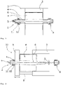
figures 1 and 2 show schematically a rotary valve in an operative position and in a nonoperative position, respectively; -
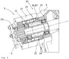
figure 3 shows an end portion of a rotary valve of the invention in an isometric and partly cut open view; -
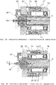
figures 4A /B show the end portion of the rotary valve of the invention in a vertical section representing two different positions of the first bearing and the second bearing; -
figure 5A /B show the end portion of the rotary valve of the invention in a horizontal section representing two different positions of the first bearing and the second bearing; -
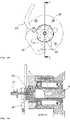
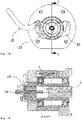
figures 6A/6B ,7A/7B and8A/8B show cross-sectional side views and frontal views of an end portion of the shaft on the side of the detachable house cover. - Whenever in the figures the same reference numerals are applied, these numerals refer to the same parts.
- With reference first to
figures 1 and 2 , arotary valve 1 is shown, comprising ahousing 2 with a removable housing cover 3 (as shown infigure 2 ), arotor 4 within thehousing 2 which is at least partially placeable outside thehousing 2 by detaching and displacing thehousing cover 3 away from thehousing 2 so as to enable access to the interior of therotary valve 1, for instance for cleaning or inspection.Figures 1 and 2 show further that anend portion 5 of ashaft 6 of therotor 4 is mounted in abearing assembly 7 supported by thehousing cover 3. - When according to
figure 1 therotor 4 is completely inside thehousing 2 with thehousing cover 3 mounted on thehousing 2, theshaft 6 of therotor 4 is also placed - usually via a sleeve - in abearing 8 on the side of thehousing 2 opposite to where the dismountable anddisplaceable housing cover 3 is positioned. - In
figure 2 it is depicted that therotor 4 is partly placed outside of thehousing 2. This can be done after first detaching thehousing cover 3 from thehousing 2, and by subsequently moving, for instance by sliding, theend portion 10 comprising thebearing assembly 7 and thehousing cover 3 away from thehousing 2 using for instance a construction withguide rails 9. This construction is however not essential, moving theend portion 10 away from thehousing 2 can also be implemented differently. - At the time the
shaft 6 of therotor 4 is only supported by thebearing 7 which is supported by thehousing cover 3, therotor shaft 6 has the tendency to drop or turndown a little distance D as depicted infigure 2 . According to the invention the problem of dropping or pitching down of therotor 4 is countered with features as further elucidated with reference to the following description and drawings. -
Figure 3 provides a detailed view at theend portion 10 of therotary valve 1.Figure 3 shows that thebearing assembly 7 comprises a first bearing 11 and a second bearing 12. These first andsecond bearings shaft 6 of the rotor in a level orientation with reference to thehousing 2 when -as shown infigure 2 - thehousing cover 3 is detached and moved away from thehousing 2. This adjustability of the bearings is provided by the feature that at least one of the first bearing 11 and the second bearing 12 is movable in a direction perpendicular to the longitudinal direction of theshaft 6. Essentially this means that the first bearing 11 and the second bearing 12 are movable with respect to each other in a direction perpendicular to the shaft's longitudinal direction. One thing and another can more clearly be seen infigures 4A /B and 5A/B. - All of the said
figures 3 ,4A /B and 5A/B show a preferred embodiment wherein the first bearing 11 is mounted in anadjustment flange 13 that is transversely movable with reference to theshaft 6 of therotor 4 and which is screw connected with a positionally fixedbase flange 14 of thehousing cover 3. In principle this could also be done vice versa. - It is shown in the respective figures that the screw connection between the
adjustment flange 13 and thebase flange 14 comprises at least onebolt 15 that is provided with screw thread mating with corresponding screw thread in an aperture of the adjustment flange 13 - these screw threads are not shown since the way they can be implemented is clearly within the scope of the skilled person. The at least onebolt 15 is further provided with atapered end portion 16 that abuts anoblique engagement surface 17 of an aperture in the positionally fixedbase flange 14. For the purpose of clarity the angle of thesurface 17 which provides the oblique positioning of thissurface 17 is shown out of scale. It is further remarked that it is also possible to apply a mirror image construction with twobolts 15 cooperating withtapered end portions 16 ofapertures 17, which cooperatingbolts 15 andapertures 17 are then on opposite sides of theshaft 6 of therotor 4. Such a construction will hereinafter be discussed for movement in the horizontal plane with reference tofigures 5A and 5B . - The difference between what is shown in
figures 4A /B andfigures 5A /B will now be discussed. -
Figures 4A and 4B provide a view at a vertical section representing two different vertical positions of the first bearing 11 and the second bearing 12 with respect to each other. - In
figure 4A thebolt 15 is at the entrance of the aperture in thebase flange 14 with theoblique surface 17, causing that the first bearing 11 is at a slightly higher position than the second bearing 12. - In
figure 4B thebolt 15 is screwed into the aperture in thebase flange 14 with theoblique surface 17, causing that the first bearing 11 is at a slightly lower position than the second bearing 12. - The combination of
figures 4A and 4B thus demonstrates that by displacing thebolt 15 into or out of the aperture in thebase flange 14, the relative vertical position of the first bearing 11 and thesecond bearing 12 can be adjusted, and accordingly theshaft 6 of therotor 4 can be maintained level. It is already remarked above that the adjustment of the first bearing 11 and the second bearing 12 with respect to each other can also be implemented with a mirror image construction with twobolts 15 cooperating withtapered end portions 16 ofapertures 17, wherein thebolts 15 andapertures 17 are on opposite sides of theshaft 6 of therotor 4. -
Figures 5A and 5B show the construction as explained with reference tofigures 4A and 4B , but now for moving therespective bearings Figures 5A and 5B provide a view at a horizontal section representing two different horizontal positions of the first bearing 11 and the second bearing 12 with respect to each other. A further discussion offigures 5A/5B concerning the operation of the construction would be similar as the above discussion with reference tofigures 4A/4B and is for sake of brevity therefore dispensed with. - The combination of
figures 4A /B and 5A/B together depict the for its simplicity preferred embodiment wherein the screw connection between theadjustment flange 13 and thebase flange 14 comprises at least threebolts 15, eachbolt 15 having a screw thread mating with corresponding screw threads in apertures of theadjustment flange 13, and whichbolts 15 are each provided with atapered end portion 16 abutting oblique engagement surfaces 17 of apertures in thebase flange 14. -
Figures 5A /B show that two of the at least threebolts 15 are on opposite positions in a horizontal plane through theshaft 6 of therotor 4 so as to provide for horizontal adjustment of theshaft 6, whereasfigures 4A/4B show that the remainingthird bolt 15 is in a vertical plane through theshaft 6 of therotor 4 and above theshaft 6 so as to provide for vertical adjustment of theshaft 6. It is again repeated that it is also possible to apply for vertical motion a mirror image construction with twobolts 15 cooperating withtapered end portions 16 ofapertures 17 on opposite sides of theshaft 6 of therotor 4. - Turning now to
figures 6A /B, 7A/B and 8A/B it is shown that an end portion of therotary valve 1 is provided with acenter bolt 18 and alock plate 19, which lockplate 19 is placeable in an operative position (as shown infigures 7A /B and 8A/8B) wherein thelock plate 19 provides support for thecenter bolt 18 to enable longitudinal movement of theshaft 6 with therotor 4 by turning of thecenter bolt 18. -
Figures 6A/6B depict that in a nonoperative position thelock plate 19 is below thecenter bolt 18 in order to prevent accidental damage of the screw thread of thecenter bolt 18, which would be possible when the rotor is placed with a high-speed in theshaft hub 23. - It is further shown that the
lock plate 19 is provided with a lock plate handle 20 to move thelock plate 19 between the nonoperative position offigures 6A/6B and the operative position offigures 7A/7B and8A/8B . -
Figures 7A/7B andfigures 8A/8B show in that connection that thelock plate 19 is provided with at least oneprotrusion 21 for engaging one ormore notches 22 on ashaft hub 23 housing theshaft 6 of therotor 4. Infigures 7A/7B thelock plate 19 has not been positioned to block rotation of therotor 4 since rotation of the rotor is then blocked by the motor connected to therotor 4. Infigures 8A/8B therotor 4 is disconnected from the motor and one of theprotrusions 21 has engaged anotch 22 on ashaft hub 23 of theshaft 6 of therotor 4 to block rotation of therotor 4. - Although the invention has been discussed in the foregoing with reference to an exemplary embodiment of the rotary valve of the invention, the invention is not restricted to this particular embodiment which can be varied in many ways without departing from the invention. The discussed exemplary embodiment shall therefore not be used to construe the appended claims strictly in accordance therewith. On the contrary the embodiment is merely intended to explain the wording of the appended claims without intent to limit the claims to this exemplary embodiment. The scope of protection of the invention shall therefore be construed in accordance with the appended claims only, wherein a possible ambiguity in the wording of the claims shall be resolved using this exemplary embodiment.
Claims (8)
- A rotary valve (1) comprising a housing (2) with a removable housing cover (3), a rotor (4) within the housing (2) which is at least partially placeable outside the housing (2) by detaching and displacing the housing cover (3) away from the housing (2) so as to enable access to an interior of the rotary valve (1), wherein an end portion (5) of a shaft (6) of the rotor (4) is mounted in a bearing assembly (7) supported by the housing cover (3), which bearing assembly (7) comprises a first bearing (11) and a second bearing (12) that are adjustable in position so as to maintain the shaft (6) of the rotor (4) in a level orientation with reference to the housing (2) when the housing cover (3) is moved away from the housing (2), and wherein the first bearing (11) and the second bearing (12) are movable with respect to each other in a direction transversely to a longitudinal direction of the shaft (6), characterized in that at least one of the first bearing (11) and second bearing (12) is mounted in an adjustment flange (13) that is transversely movable with reference to the shaft (6) of the rotor (4) and which is screw connected with a base flange (14) of the housing cover (3).
- The rotary valve of claim 1, characterized in that the screw connection between the adjustment flange (13) and the base flange (14) comprises at least one bolt (15) provided with screw thread that is mating with corresponding screw thread in an aperture of the adjustment flange (13), which at least one bolt (15) is provided with a tapered end portion (16) that abuts an oblique engagement surface (17) of an aperture in the base flange (14).
- The rotary valve of claim 1 or 2, characterized in that the screw connection between the adjustment flange (13) and the base flange (14) comprises at least three bolts (15), each bolt (15) having screw thread mating with corresponding screw thread in apertures of the adjustment flange (13), which bolts (15) are each provided with a tapered end portion (16) abutting oblique engagement surfaces (17) of apertures in the base flange (14).
- The rotary valve of claim 3, characterized in that two of the at least three bolts (15) are on opposite positions in a horizontal plane through the shaft (6) of the rotor (4) so as to provide for horizontal adjustment of the shaft (6), whereas the third bolt (15) is in a vertical plane through the shaft (6) of the rotor (4) and above the shaft (6) so as to provide for vertical adjustment of the shaft (6).
- The rotary valve of any one of claims 1 - 4, characterized in that an end portion of the rotary valve (1) is provided with a center bolt (18) and a lock plate (19), which lock plate (19) is placeable in an operative position wherein the lock plate (19) provides support for the center bolt (18) to enable longitudinal movement of the shaft (6) with the rotor (4) by turning of the center bolt (18).
- The rotary valve of claim 5, characterized in that in a nonoperative position the lock plate (19) is below the center bolt (18).
- The rotary valve of claim 5 or 6, characterized in that the lock plate (19) is provided with a lock plate handle (20) to move the swivable lock plate (19) between the nonoperative position and the operative position.
- The rotary valve of claim 7, characterized in that the lock plate (19) is provided with at least one protrusion (21) for engaging one or more notches (22) on a shaft hub (23) which houses the shaft (6) of the rotor (4).
Applications Claiming Priority (1)
| Application Number | Priority Date | Filing Date | Title |
|---|---|---|---|
| NL2026544A NL2026544B1 (en) | 2020-09-25 | 2020-09-25 | A rotary valve |
Publications (2)
| Publication Number | Publication Date |
|---|---|
| EP3974354A1 true EP3974354A1 (en) | 2022-03-30 |
| EP3974354B1 EP3974354B1 (en) | 2023-06-14 |
Family
ID=73498234
Family Applications (1)
| Application Number | Title | Priority Date | Filing Date |
|---|---|---|---|
| EP21196880.5A Active EP3974354B1 (en) | 2020-09-25 | 2021-09-15 | A rotary valve |
Country Status (8)
| Country | Link |
|---|---|
| US (1) | US11506299B2 (en) |
| EP (1) | EP3974354B1 (en) |
| JP (1) | JP7777413B2 (en) |
| KR (1) | KR20220041759A (en) |
| CN (1) | CN114251372B (en) |
| CA (1) | CA3131582A1 (en) |
| ES (1) | ES2952684T3 (en) |
| NL (1) | NL2026544B1 (en) |
Citations (6)
| Publication number | Priority date | Publication date | Assignee | Title |
|---|---|---|---|---|
| US3130879A (en) * | 1960-08-26 | 1964-04-28 | Black Clawson Co | Rotary feed valve |
| NL8902680A (en) * | 1989-10-30 | 1991-05-16 | Westinghouse Brake & Signal | ROTARY VALVE, PARTICULARLY FOR DOSING DRY SUBSTANCES FROM ONE SYSTEM PART IN THE OTHER. |
| DE4135594A1 (en) * | 1991-10-29 | 1993-05-06 | Avt Anlagen- Und Verfahrenstechnik Gmbh, 7987 Weingarten, De | Cellular rotary wheel for dispensing loose bulk material - is mounted on shaft with hydraulic compensation by radial bearing displacement for shaft curvature under load |
| DE4214467C1 (en) * | 1992-05-06 | 1993-11-11 | Reimelt Dietrich Kg | Cell wheel lock |
| US6186164B1 (en) | 1998-11-27 | 2001-02-13 | Waeschle Gmbh | Rotary valve comprising a drawing device |
| EP3000754A1 (en) | 2014-09-26 | 2016-03-30 | Rotaval Limited | Rotary valve |
Family Cites Families (20)
| Publication number | Priority date | Publication date | Assignee | Title |
|---|---|---|---|---|
| US434479A (en) * | 1890-08-19 | Ball-bearing | ||
| US1259751A (en) * | 1917-09-04 | 1918-03-19 | William O Kuhn | Roller-bearing. |
| US2373859A (en) * | 1943-06-15 | 1945-04-17 | Condenser Dev Corp | Rotor mounting means for variable tuning devices |
| US2525744A (en) * | 1947-03-03 | 1950-10-10 | Dunlop Tire & Rubber Corp | Calender |
| US2510896A (en) * | 1949-01-17 | 1950-06-06 | Letourneau Inc | In-place bearing adjustment wrench |
| US2826462A (en) * | 1955-03-31 | 1958-03-11 | Orenda Engines Ltd | Bearing alignment adjustor |
| US5368311A (en) * | 1976-04-16 | 1994-11-29 | Heyl; Robert D. | Shaft seal assembly for a rotary valve |
| US4622730A (en) * | 1984-03-30 | 1986-11-18 | Rolf Steinbock | Apparatus to mechanically stress a bolt-type fastener |
| US5002084A (en) * | 1990-04-12 | 1991-03-26 | Abb Sprout-Bauer, Inc. | Quick clean rotary valve |
| JP3040525B2 (en) * | 1990-11-30 | 2000-05-15 | 株式会社リコー | Image forming device |
| US5161904A (en) * | 1991-07-10 | 1992-11-10 | Eaton Corporation | Transmission countershaft rotary bearing shim |
| JP2001199545A (en) * | 2000-01-12 | 2001-07-24 | Tsukasa Kogyo Kk | Rotary valve |
| FI106741B (en) * | 2000-03-16 | 2001-03-30 | Metso Paper Inc | Bendable roller with composite mantle |
| US7794153B2 (en) * | 2007-12-07 | 2010-09-14 | Ford Global Technologies, Llc | Adjusting and maintaining bearing preload in an axle assembly |
| DE102008035204B3 (en) * | 2008-07-28 | 2010-01-21 | Ab Skf | role |
| DE102009052352A1 (en) * | 2009-11-07 | 2011-05-12 | Siemens Geared Motors Gmbh | A journal bearing arrangement |
| GB2498986B (en) * | 2012-02-01 | 2014-02-26 | Rotaval Ltd | Rotary valve |
| US9533701B2 (en) * | 2012-08-07 | 2017-01-03 | Steering Solutions Ip Holding Corporation | Steering column assist system |
| JP2019068524A (en) * | 2017-09-28 | 2019-04-25 | 日本電産株式会社 | motor |
| ES3000811T3 (en) * | 2018-04-06 | 2025-03-03 | Entecnia Consulting S L U | Rotary pump |
-
2020
- 2020-09-25 NL NL2026544A patent/NL2026544B1/en active
-
2021
- 2021-09-15 EP EP21196880.5A patent/EP3974354B1/en active Active
- 2021-09-15 ES ES21196880T patent/ES2952684T3/en active Active
- 2021-09-20 US US17/479,688 patent/US11506299B2/en active Active
- 2021-09-22 CA CA3131582A patent/CA3131582A1/en active Pending
- 2021-09-24 CN CN202111121864.5A patent/CN114251372B/en active Active
- 2021-09-24 JP JP2021155607A patent/JP7777413B2/en active Active
- 2021-09-24 KR KR1020210126136A patent/KR20220041759A/en active Pending
Patent Citations (6)
| Publication number | Priority date | Publication date | Assignee | Title |
|---|---|---|---|---|
| US3130879A (en) * | 1960-08-26 | 1964-04-28 | Black Clawson Co | Rotary feed valve |
| NL8902680A (en) * | 1989-10-30 | 1991-05-16 | Westinghouse Brake & Signal | ROTARY VALVE, PARTICULARLY FOR DOSING DRY SUBSTANCES FROM ONE SYSTEM PART IN THE OTHER. |
| DE4135594A1 (en) * | 1991-10-29 | 1993-05-06 | Avt Anlagen- Und Verfahrenstechnik Gmbh, 7987 Weingarten, De | Cellular rotary wheel for dispensing loose bulk material - is mounted on shaft with hydraulic compensation by radial bearing displacement for shaft curvature under load |
| DE4214467C1 (en) * | 1992-05-06 | 1993-11-11 | Reimelt Dietrich Kg | Cell wheel lock |
| US6186164B1 (en) | 1998-11-27 | 2001-02-13 | Waeschle Gmbh | Rotary valve comprising a drawing device |
| EP3000754A1 (en) | 2014-09-26 | 2016-03-30 | Rotaval Limited | Rotary valve |
Also Published As
| Publication number | Publication date |
|---|---|
| NL2026544B1 (en) | 2022-05-30 |
| JP2022054451A (en) | 2022-04-06 |
| CN114251372B (en) | 2025-12-09 |
| US11506299B2 (en) | 2022-11-22 |
| KR20220041759A (en) | 2022-04-01 |
| JP7777413B2 (en) | 2025-11-28 |
| ES2952684T3 (en) | 2023-11-03 |
| CA3131582A1 (en) | 2022-03-25 |
| US20220099208A1 (en) | 2022-03-31 |
| CN114251372A (en) | 2022-03-29 |
| EP3974354B1 (en) | 2023-06-14 |
Similar Documents
| Publication | Publication Date | Title |
|---|---|---|
| US20200018349A1 (en) | Device for rotationally and translationally moving an object | |
| US8152470B2 (en) | Device for the adjustment of the pitch of a motor blade of a wind turbine | |
| EP2937619A1 (en) | Rotatable connection with limitation of the rotational angle | |
| EP0614035A1 (en) | Ceiling mount | |
| EP3559536B1 (en) | Camera control methods and apparatus | |
| EP3974354B1 (en) | A rotary valve | |
| CA2707739A1 (en) | Device and method for adjusting a position of an optical component | |
| DE4436199C1 (en) | Radius actuator e.g for machinery safety switches | |
| EP2949845B1 (en) | Adjustable flap bearing | |
| EP4446259A2 (en) | Connection device for assembling a holder for components of a conveyor device and conveyor device for transporting piece goods | |
| DE202012104544U1 (en) | Downlight | |
| DE10154967B4 (en) | Clamping device for fastening components to retaining elements provided with a T-slot | |
| JP2026506976A (en) | Translation-rotation fittings and furniture or household appliances | |
| DE202006014797U1 (en) | Panorama body | |
| EP0140876B1 (en) | A device in a rotating shaft supporting bearing element | |
| US20240175543A1 (en) | Adjustable rotor support and rotary heat exchanger with such support | |
| DE102017123920B3 (en) | adjusting | |
| EP4153017B1 (en) | Container receiving device and holder for same | |
| EP4542300B1 (en) | Projector adjustment system | |
| US12414628B2 (en) | Height-adjustable rotary fitting for a cabinet comprising a rotating supporting column | |
| DE102004011362B4 (en) | Device for tilting objects and an optical tilting device | |
| AT521663A1 (en) | Swivel joint for a wooden trestle | |
| AT501026A2 (en) | RECESSED LUMINAIRE WITH A FIXING DEVICE FOR FIXING IT IN AN INSTALLATION OPENING | |
| DE202024001458U1 (en) | Fitting and fitting system for a component, component and adjustable device | |
| DE29810585U1 (en) | Positioning bolt of a quick-pass system |
Legal Events
| Date | Code | Title | Description |
|---|---|---|---|
| PUAI | Public reference made under article 153(3) epc to a published international application that has entered the european phase |
Free format text: ORIGINAL CODE: 0009012 |
|
| STAA | Information on the status of an ep patent application or granted ep patent |
Free format text: STATUS: THE APPLICATION HAS BEEN PUBLISHED |
|
| AK | Designated contracting states |
Kind code of ref document: A1 Designated state(s): AL AT BE BG CH CY CZ DE DK EE ES FI FR GB GR HR HU IE IS IT LI LT LU LV MC MK MT NL NO PL PT RO RS SE SI SK SM TR |
|
| STAA | Information on the status of an ep patent application or granted ep patent |
Free format text: STATUS: REQUEST FOR EXAMINATION WAS MADE |
|
| 17P | Request for examination filed |
Effective date: 20220930 |
|
| RBV | Designated contracting states (corrected) |
Designated state(s): AL AT BE BG CH CY CZ DE DK EE ES FI FR GB GR HR HU IE IS IT LI LT LU LV MC MK MT NL NO PL PT RO RS SE SI SK SM TR |
|
| RIC1 | Information provided on ipc code assigned before grant |
Ipc: F16K 27/12 20060101ALI20230118BHEP Ipc: F16K 27/06 20060101ALI20230118BHEP Ipc: F16C 41/04 20060101ALI20230118BHEP Ipc: F16C 35/073 20060101ALI20230118BHEP Ipc: F16C 35/067 20060101ALI20230118BHEP Ipc: F16C 19/54 20060101ALI20230118BHEP Ipc: B65G 53/46 20060101AFI20230118BHEP |
|
| GRAP | Despatch of communication of intention to grant a patent |
Free format text: ORIGINAL CODE: EPIDOSNIGR1 |
|
| STAA | Information on the status of an ep patent application or granted ep patent |
Free format text: STATUS: GRANT OF PATENT IS INTENDED |
|
| INTG | Intention to grant announced |
Effective date: 20230228 |
|
| GRAS | Grant fee paid |
Free format text: ORIGINAL CODE: EPIDOSNIGR3 |
|
| GRAA | (expected) grant |
Free format text: ORIGINAL CODE: 0009210 |
|
| STAA | Information on the status of an ep patent application or granted ep patent |
Free format text: STATUS: THE PATENT HAS BEEN GRANTED |
|
| AK | Designated contracting states |
Kind code of ref document: B1 Designated state(s): AL AT BE BG CH CY CZ DE DK EE ES FI FR GB GR HR HU IE IS IT LI LT LU LV MC MK MT NL NO PL PT RO RS SE SI SK SM TR |
|
| REG | Reference to a national code |
Ref country code: CH Ref legal event code: EP |
|
| P01 | Opt-out of the competence of the unified patent court (upc) registered |
Effective date: 20230514 |
|
| REG | Reference to a national code |
Ref country code: DE Ref legal event code: R096 Ref document number: 602021002922 Country of ref document: DE |
|
| REG | Reference to a national code |
Ref country code: AT Ref legal event code: REF Ref document number: 1579115 Country of ref document: AT Kind code of ref document: T Effective date: 20230715 |
|
| REG | Reference to a national code |
Ref country code: NL Ref legal event code: FP |
|
| REG | Reference to a national code |
Ref country code: LT Ref legal event code: MG9D |
|
| PG25 | Lapsed in a contracting state [announced via postgrant information from national office to epo] |
Ref country code: SE Free format text: LAPSE BECAUSE OF FAILURE TO SUBMIT A TRANSLATION OF THE DESCRIPTION OR TO PAY THE FEE WITHIN THE PRESCRIBED TIME-LIMIT Effective date: 20230614 Ref country code: NO Free format text: LAPSE BECAUSE OF FAILURE TO SUBMIT A TRANSLATION OF THE DESCRIPTION OR TO PAY THE FEE WITHIN THE PRESCRIBED TIME-LIMIT Effective date: 20230914 |
|
| REG | Reference to a national code |
Ref country code: ES Ref legal event code: FG2A Ref document number: 2952684 Country of ref document: ES Kind code of ref document: T3 Effective date: 20231103 |
|
| REG | Reference to a national code |
Ref country code: AT Ref legal event code: MK05 Ref document number: 1579115 Country of ref document: AT Kind code of ref document: T Effective date: 20230614 |
|
| PG25 | Lapsed in a contracting state [announced via postgrant information from national office to epo] |
Ref country code: RS Free format text: LAPSE BECAUSE OF FAILURE TO SUBMIT A TRANSLATION OF THE DESCRIPTION OR TO PAY THE FEE WITHIN THE PRESCRIBED TIME-LIMIT Effective date: 20230614 Ref country code: LV Free format text: LAPSE BECAUSE OF FAILURE TO SUBMIT A TRANSLATION OF THE DESCRIPTION OR TO PAY THE FEE WITHIN THE PRESCRIBED TIME-LIMIT Effective date: 20230614 Ref country code: LT Free format text: LAPSE BECAUSE OF FAILURE TO SUBMIT A TRANSLATION OF THE DESCRIPTION OR TO PAY THE FEE WITHIN THE PRESCRIBED TIME-LIMIT Effective date: 20230614 Ref country code: HR Free format text: LAPSE BECAUSE OF FAILURE TO SUBMIT A TRANSLATION OF THE DESCRIPTION OR TO PAY THE FEE WITHIN THE PRESCRIBED TIME-LIMIT Effective date: 20230614 Ref country code: GR Free format text: LAPSE BECAUSE OF FAILURE TO SUBMIT A TRANSLATION OF THE DESCRIPTION OR TO PAY THE FEE WITHIN THE PRESCRIBED TIME-LIMIT Effective date: 20230915 |
|
| PG25 | Lapsed in a contracting state [announced via postgrant information from national office to epo] |
Ref country code: FI Free format text: LAPSE BECAUSE OF FAILURE TO SUBMIT A TRANSLATION OF THE DESCRIPTION OR TO PAY THE FEE WITHIN THE PRESCRIBED TIME-LIMIT Effective date: 20230614 |
|
| PG25 | Lapsed in a contracting state [announced via postgrant information from national office to epo] |
Ref country code: SK Free format text: LAPSE BECAUSE OF FAILURE TO SUBMIT A TRANSLATION OF THE DESCRIPTION OR TO PAY THE FEE WITHIN THE PRESCRIBED TIME-LIMIT Effective date: 20230614 |
|
| PG25 | Lapsed in a contracting state [announced via postgrant information from national office to epo] |
Ref country code: IS Free format text: LAPSE BECAUSE OF FAILURE TO SUBMIT A TRANSLATION OF THE DESCRIPTION OR TO PAY THE FEE WITHIN THE PRESCRIBED TIME-LIMIT Effective date: 20231014 |
|
| PG25 | Lapsed in a contracting state [announced via postgrant information from national office to epo] |
Ref country code: SM Free format text: LAPSE BECAUSE OF FAILURE TO SUBMIT A TRANSLATION OF THE DESCRIPTION OR TO PAY THE FEE WITHIN THE PRESCRIBED TIME-LIMIT Effective date: 20230614 Ref country code: SK Free format text: LAPSE BECAUSE OF FAILURE TO SUBMIT A TRANSLATION OF THE DESCRIPTION OR TO PAY THE FEE WITHIN THE PRESCRIBED TIME-LIMIT Effective date: 20230614 Ref country code: RO Free format text: LAPSE BECAUSE OF FAILURE TO SUBMIT A TRANSLATION OF THE DESCRIPTION OR TO PAY THE FEE WITHIN THE PRESCRIBED TIME-LIMIT Effective date: 20230614 Ref country code: PT Free format text: LAPSE BECAUSE OF FAILURE TO SUBMIT A TRANSLATION OF THE DESCRIPTION OR TO PAY THE FEE WITHIN THE PRESCRIBED TIME-LIMIT Effective date: 20231016 Ref country code: IS Free format text: LAPSE BECAUSE OF FAILURE TO SUBMIT A TRANSLATION OF THE DESCRIPTION OR TO PAY THE FEE WITHIN THE PRESCRIBED TIME-LIMIT Effective date: 20231014 Ref country code: EE Free format text: LAPSE BECAUSE OF FAILURE TO SUBMIT A TRANSLATION OF THE DESCRIPTION OR TO PAY THE FEE WITHIN THE PRESCRIBED TIME-LIMIT Effective date: 20230614 Ref country code: CZ Free format text: LAPSE BECAUSE OF FAILURE TO SUBMIT A TRANSLATION OF THE DESCRIPTION OR TO PAY THE FEE WITHIN THE PRESCRIBED TIME-LIMIT Effective date: 20230614 Ref country code: AT Free format text: LAPSE BECAUSE OF FAILURE TO SUBMIT A TRANSLATION OF THE DESCRIPTION OR TO PAY THE FEE WITHIN THE PRESCRIBED TIME-LIMIT Effective date: 20230614 |
|
| PG25 | Lapsed in a contracting state [announced via postgrant information from national office to epo] |
Ref country code: PL Free format text: LAPSE BECAUSE OF FAILURE TO SUBMIT A TRANSLATION OF THE DESCRIPTION OR TO PAY THE FEE WITHIN THE PRESCRIBED TIME-LIMIT Effective date: 20230614 |
|
| REG | Reference to a national code |
Ref country code: DE Ref legal event code: R097 Ref document number: 602021002922 Country of ref document: DE |
|
| PLBE | No opposition filed within time limit |
Free format text: ORIGINAL CODE: 0009261 |
|
| STAA | Information on the status of an ep patent application or granted ep patent |
Free format text: STATUS: NO OPPOSITION FILED WITHIN TIME LIMIT |
|
| PG25 | Lapsed in a contracting state [announced via postgrant information from national office to epo] |
Ref country code: DK Free format text: LAPSE BECAUSE OF FAILURE TO SUBMIT A TRANSLATION OF THE DESCRIPTION OR TO PAY THE FEE WITHIN THE PRESCRIBED TIME-LIMIT Effective date: 20230614 |
|
| PG25 | Lapsed in a contracting state [announced via postgrant information from national office to epo] |
Ref country code: SI Free format text: LAPSE BECAUSE OF FAILURE TO SUBMIT A TRANSLATION OF THE DESCRIPTION OR TO PAY THE FEE WITHIN THE PRESCRIBED TIME-LIMIT Effective date: 20230614 |
|
| PG25 | Lapsed in a contracting state [announced via postgrant information from national office to epo] |
Ref country code: LU Free format text: LAPSE BECAUSE OF NON-PAYMENT OF DUE FEES Effective date: 20230915 |
|
| 26N | No opposition filed |
Effective date: 20240315 |
|
| REG | Reference to a national code |
Ref country code: BE Ref legal event code: MM Effective date: 20230930 |
|
| PG25 | Lapsed in a contracting state [announced via postgrant information from national office to epo] |
Ref country code: SI Free format text: LAPSE BECAUSE OF FAILURE TO SUBMIT A TRANSLATION OF THE DESCRIPTION OR TO PAY THE FEE WITHIN THE PRESCRIBED TIME-LIMIT Effective date: 20230614 Ref country code: LU Free format text: LAPSE BECAUSE OF NON-PAYMENT OF DUE FEES Effective date: 20230915 Ref country code: MC Free format text: LAPSE BECAUSE OF FAILURE TO SUBMIT A TRANSLATION OF THE DESCRIPTION OR TO PAY THE FEE WITHIN THE PRESCRIBED TIME-LIMIT Effective date: 20230614 |
|
| REG | Reference to a national code |
Ref country code: IE Ref legal event code: MM4A |
|
| PG25 | Lapsed in a contracting state [announced via postgrant information from national office to epo] |
Ref country code: IE Free format text: LAPSE BECAUSE OF NON-PAYMENT OF DUE FEES Effective date: 20230915 |
|
| PG25 | Lapsed in a contracting state [announced via postgrant information from national office to epo] |
Ref country code: IE Free format text: LAPSE BECAUSE OF NON-PAYMENT OF DUE FEES Effective date: 20230915 |
|
| PG25 | Lapsed in a contracting state [announced via postgrant information from national office to epo] |
Ref country code: BE Free format text: LAPSE BECAUSE OF NON-PAYMENT OF DUE FEES Effective date: 20230930 |
|
| PG25 | Lapsed in a contracting state [announced via postgrant information from national office to epo] |
Ref country code: BG Free format text: LAPSE BECAUSE OF FAILURE TO SUBMIT A TRANSLATION OF THE DESCRIPTION OR TO PAY THE FEE WITHIN THE PRESCRIBED TIME-LIMIT Effective date: 20230614 |
|
| PG25 | Lapsed in a contracting state [announced via postgrant information from national office to epo] |
Ref country code: BG Free format text: LAPSE BECAUSE OF FAILURE TO SUBMIT A TRANSLATION OF THE DESCRIPTION OR TO PAY THE FEE WITHIN THE PRESCRIBED TIME-LIMIT Effective date: 20230614 |
|
| PG25 | Lapsed in a contracting state [announced via postgrant information from national office to epo] |
Ref country code: CY Free format text: LAPSE BECAUSE OF FAILURE TO SUBMIT A TRANSLATION OF THE DESCRIPTION OR TO PAY THE FEE WITHIN THE PRESCRIBED TIME-LIMIT; INVALID AB INITIO Effective date: 20210915 |
|
| PG25 | Lapsed in a contracting state [announced via postgrant information from national office to epo] |
Ref country code: HU Free format text: LAPSE BECAUSE OF FAILURE TO SUBMIT A TRANSLATION OF THE DESCRIPTION OR TO PAY THE FEE WITHIN THE PRESCRIBED TIME-LIMIT; INVALID AB INITIO Effective date: 20210915 |
|
| REG | Reference to a national code |
Ref country code: CH Ref legal event code: U11 Free format text: ST27 STATUS EVENT CODE: U-0-0-U10-U11 (AS PROVIDED BY THE NATIONAL OFFICE) Effective date: 20251001 |
|
| PGFP | Annual fee paid to national office [announced via postgrant information from national office to epo] |
Ref country code: DE Payment date: 20250929 Year of fee payment: 5 |
|
| PGFP | Annual fee paid to national office [announced via postgrant information from national office to epo] |
Ref country code: NL Payment date: 20250926 Year of fee payment: 5 Ref country code: IT Payment date: 20250919 Year of fee payment: 5 |
|
| PGFP | Annual fee paid to national office [announced via postgrant information from national office to epo] |
Ref country code: GB Payment date: 20250929 Year of fee payment: 5 |
|
| PGFP | Annual fee paid to national office [announced via postgrant information from national office to epo] |
Ref country code: FR Payment date: 20250925 Year of fee payment: 5 |
|
| PG25 | Lapsed in a contracting state [announced via postgrant information from national office to epo] |
Ref country code: TR Free format text: LAPSE BECAUSE OF FAILURE TO SUBMIT A TRANSLATION OF THE DESCRIPTION OR TO PAY THE FEE WITHIN THE PRESCRIBED TIME-LIMIT Effective date: 20230614 |
|
| PGFP | Annual fee paid to national office [announced via postgrant information from national office to epo] |
Ref country code: CH Payment date: 20251001 Year of fee payment: 5 |
|
| PGFP | Annual fee paid to national office [announced via postgrant information from national office to epo] |
Ref country code: ES Payment date: 20251001 Year of fee payment: 5 |