EP3974352B1 - Stapler mit schiebemechanismus - Google Patents
Stapler mit schiebemechanismus Download PDFInfo
- Publication number
- EP3974352B1 EP3974352B1 EP21275008.7A EP21275008A EP3974352B1 EP 3974352 B1 EP3974352 B1 EP 3974352B1 EP 21275008 A EP21275008 A EP 21275008A EP 3974352 B1 EP3974352 B1 EP 3974352B1
- Authority
- EP
- European Patent Office
- Prior art keywords
- conveyor
- stacker
- inclination
- pair
- slot
- Prior art date
- Legal status (The legal status is an assumption and is not a legal conclusion. Google has not performed a legal analysis and makes no representation as to the accuracy of the status listed.)
- Active
Links
Images


Classifications
-
- B—PERFORMING OPERATIONS; TRANSPORTING
- B65—CONVEYING; PACKING; STORING; HANDLING THIN OR FILAMENTARY MATERIAL
- B65G—TRANSPORT OR STORAGE DEVICES, e.g. CONVEYORS FOR LOADING OR TIPPING, SHOP CONVEYOR SYSTEMS OR PNEUMATIC TUBE CONVEYORS
- B65G41/00—Supporting frames or bases for conveyors as a whole, e.g. transportable conveyor frames
- B65G41/001—Supporting frames or bases for conveyors as a whole, e.g. transportable conveyor frames with the conveyor adjustably mounted on the supporting frame or base
- B65G41/002—Pivotably mounted
-
- B—PERFORMING OPERATIONS; TRANSPORTING
- B65—CONVEYING; PACKING; STORING; HANDLING THIN OR FILAMENTARY MATERIAL
- B65G—TRANSPORT OR STORAGE DEVICES, e.g. CONVEYORS FOR LOADING OR TIPPING, SHOP CONVEYOR SYSTEMS OR PNEUMATIC TUBE CONVEYORS
- B65G65/00—Loading or unloading
- B65G65/28—Piling or unpiling loose materials in bulk, e.g. coal, manure, timber, not otherwise provided for
-
- B—PERFORMING OPERATIONS; TRANSPORTING
- B65—CONVEYING; PACKING; STORING; HANDLING THIN OR FILAMENTARY MATERIAL
- B65G—TRANSPORT OR STORAGE DEVICES, e.g. CONVEYORS FOR LOADING OR TIPPING, SHOP CONVEYOR SYSTEMS OR PNEUMATIC TUBE CONVEYORS
- B65G21/00—Supporting or protective framework or housings for endless load-carriers or traction elements of belt or chain conveyors
- B65G21/10—Supporting or protective framework or housings for endless load-carriers or traction elements of belt or chain conveyors movable, or having interchangeable or relatively movable parts; Devices for moving framework or parts thereof
- B65G21/14—Supporting or protective framework or housings for endless load-carriers or traction elements of belt or chain conveyors movable, or having interchangeable or relatively movable parts; Devices for moving framework or parts thereof to allow adjustment of length or configuration of load-carrier or traction element
-
- B—PERFORMING OPERATIONS; TRANSPORTING
- B65—CONVEYING; PACKING; STORING; HANDLING THIN OR FILAMENTARY MATERIAL
- B65G—TRANSPORT OR STORAGE DEVICES, e.g. CONVEYORS FOR LOADING OR TIPPING, SHOP CONVEYOR SYSTEMS OR PNEUMATIC TUBE CONVEYORS
- B65G41/00—Supporting frames or bases for conveyors as a whole, e.g. transportable conveyor frames
- B65G41/001—Supporting frames or bases for conveyors as a whole, e.g. transportable conveyor frames with the conveyor adjustably mounted on the supporting frame or base
- B65G41/005—Supporting frames or bases for conveyors as a whole, e.g. transportable conveyor frames with the conveyor adjustably mounted on the supporting frame or base mounted for both pivotal and linear movement
-
- B—PERFORMING OPERATIONS; TRANSPORTING
- B65—CONVEYING; PACKING; STORING; HANDLING THIN OR FILAMENTARY MATERIAL
- B65G—TRANSPORT OR STORAGE DEVICES, e.g. CONVEYORS FOR LOADING OR TIPPING, SHOP CONVEYOR SYSTEMS OR PNEUMATIC TUBE CONVEYORS
- B65G41/00—Supporting frames or bases for conveyors as a whole, e.g. transportable conveyor frames
- B65G41/007—Means for moving conveyor frames and control arrangements therefor
- B65G41/008—Means for moving conveyor frames and control arrangements therefor frames mounted on wheels or caterpillar
Definitions
- Embodiments herein relate to tracked, portable radial belt conveyors with wheels used to convey bulk material from a first location to a second location, and a system for changing the inclination of the conveyor.
- Radial stackers have been used for many years to stack bulk materials such as aggregate for road construction, grain and coal. Radial stackers, which swing around in a radius to stack material in an arc, permit substantially more material to be stacked than is possible using a conventional stationary stacker that permits only a single conical stack.
- Radial stackers typically include a wheeled axle disposed between a hopper and the top of the stacker from which the material is discharged.
- the wheels permit the stacker to be swung in an arc, with the hopper including a pivot plate on which the stacker pivots.
- tracked drives have been used in quarries, agricultural and mining operations to enable equipment to be moved over harsh terrain for ideal positioning for stacking operations. While tracked vehicles have proven to be of great benefit for such purposes, the use of tracks instead of wheels makes it more difficult to shift a stacker radially to facilitate the stacking of material in an arc instead of a cone. Also, because tracked vehicles are not typically permitted to be driven on road surfaces, they are normally loaded onto flatbed trucks for transit from one work site to another. These two drawbacks with the use of tracks has to a certain extent limited the use of tracked vehicles.
- McCloskey International has developed a line of stackers with both tracks and wheels in which the wheels can pivot by so the stacker can either be operated in a radial fashion at a job site or can be operated in a longitudinal disposition to permit the stacker to be hauled down a road.
- Such systems are disclosed in the following U. S. patents: Nos. 10,011,443 ; 10,414,598 ; 10,414,599 ; 10,450,153 ; 10,556,752 ; and 10,683,177 .
- Another more primitive design in that it does not include pivotable wheels is disclosed in EP 2883819 .
- United States Patent No. 10,414,598 disclosing the preamble of claim 1, discloses a tracked, portable radial stacker for stockpiling bulk material including a linear conveyor having a rear portion and a front portion and being designed to carry bulk material from a low position adjacent the rear portion to a higher position adjacent the front portion.
- a foot may be disposed adjacent the rear portion of the conveyor and designed to selectively contact the ground to facilitate pivoting of the conveyor.
- a continuous track system may include a frame to which the conveyor is mounted, the track system including a pair of driven, parallel tracks designed to contact the ground to convey the stacker from one position to another, and to be lifted off the ground when desired.
- a pair of mid-wheels may be mounted to the frame to be moveable between a raised position in which they do not contact the ground and a lowered position in which they contact the ground and lift the tracks off the ground.
- a rear wheel may be mounted adjacent the rear portion of the conveyor to be moveable between a raised position in which it does not contact the ground and a lowered position in which it contacts the ground and lifts the tracks off the ground to permit movement of the conveyor on the rear wheel.
- Coupled may mean that two or more elements are in direct physical or electrical contact. However, “coupled” may also mean that two or more elements are not in direct contact with each other, but yet still cooperate or interact with each other.
- a phrase in the form "A/B” or in the form “A and/or B” means (A), (B), or (A and B).
- a phrase in the form "at least one of A, B, and C” means (A), (B), (C), (A and B), (A and C), (B and C), or (A, B and C).
- a phrase in the form "(A)B” means (B) or (AB) that is, A is an optional element.
- One aspect of the invention is a tracked, portable radial stacker for stockpiling bulk material according to claim 1.
- a mounting system may be fixed to the rear portion of the conveyor, with upper and lower rearwardly extending, hydraulically-powered, telescoping frame members extending between the carriage frame and the mounting system for controlling the elevation of the rear portion of the conveyor and thereby controlling inclination of the conveyor.
- the mounting system may define a longitudinally extending slot, with a trolley slidably mounted within the slot.
- the rearwardly extending frame members may be pivotally mounted to the trolley so that as the rearwardly extending frame members telescopingly extend and retract, the trolley slides forwardly and rearwardly in the slot, thereby reducing a tendency of the rear portion of the conveyor to longitudinally shift as the degree of inclination of the conveyor is changed.
- the mounting system may include a plate that is fixed to the conveyor, and the slot may be defined in the plate.
- the rearwardly extending frame members are according to the invention bemounted to the trolley at a pair of longitudinally spaced mounting points.
- the trolley may be slidably mounted to the slot by a pair of rollers.
- the reduction of the tendency of the rear portion of the conveyor to longitudinally shift as the degree of inclination of the conveyor is changed may largely eliminate the need to reposition the stacker while the stacker is operating.
- a hopper may be positioned at the rear portion of the conveyor, and a pivot pad may be disposed below the hopper on which the stacker pivots as the conveyor is being radially shifted from one position to another, whereby the reduction of the tendency of the rear portion of the conveyor to longitudinally shift as the degree of inclination of the conveyor is changed largely eliminates the need to reposition the pivot pad while the stacker is operating.
- the telescoping frame members are mounted to the trolley at spaced mounting points so that by extending and retracting the frame members, the rear portion of the conveyor can be raised and lowered, thereby changing inclination of the conveyor, wherein the trolley moving longitudinally in the slot takes up longitudinal movement of the conveyor as the inclination of the conveyor is changed.
- the mounting system may include a plate fixed to the underside of the conveyor and wherein the slot is defined in the plate, the slidable mounting of the trolley within the slot comprises a plurality of rollers that facilitate the trolley moving rearwardly in the slot as the inclination of the conveyor is reduced and moving forwardly as the inclination of the conveyor is increased.
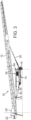
- Figs. 1 and 2 represent views of a prior art McCloskey International stacker, generally as disclosed in the aforementioned McCloskey patents.
- the stacker identified generally at 10pa (for "prior art"), includes a conveyor 12pa, a track system 14pa, a wheel system 16pa, a hopper 20pa, a counterweight 22pa, and a pivot pad 24pa.
- the figures show the track system 14pa elevated off the ground with wheel system 16pa supporting the track system off the ground, the wheel system being in a radial disposition (sometimes referred to herein as a lateral disposition). With the tracks and wheels in this position, the stacker can be shifted radially to pivot on pivot pad 24pa so that bulk material can be stacked in an arc-shaped stack or in a plurality of stacks arrayed in an arc.
- Wheel system 16pa can be raised so track system 14pa contacts the ground to permit the stacker to be maneuvered around a work site. With the wheel system in this elevated position, the wheels can be pivoted by so that they extend in a longitudinal direction for movement of the stacker in a longitudinal direction when the wheels are lowered to the ground.
- Stacker 10pa also includes a pair of forwardly extending, telescoping support frames 26pa on each lateral side of conveyor 12pa. The extension and retraction of these frames is controlled and driven by a pair of hydraulic rams, one in each forward support frame. Two pairs of rearwardly extending support frames 28pa and 30pa are also included, again with one of the pair on each side of the conveyor. Only one of the pair of support frames shows in the depicted stacker so from this point on the pair will be described as a single frame. Each of the rearwardly extending support frames 28pa and 30pa connect to conveyor 12pa at a common pivot point 32pa.
- Upper rear support frame 28pa and lower rear support frame 30pa typically extend rearwardly from a carriage frame 34pa.
- the top rearwardly extending support frame 28pa is typically not telescoping while the lower rearwardly extending support frame 30pa typically is telescoping and incorporates a hydraulic ram to control the extension and retraction thereof.
- the inclination of conveyor 10pa is regularly adjusted to accommodate for the ever-increasing height of the stack.
- Changing the inclination is performed by extending or retracting forward support frame 26pa and lower rear support frame 30pa.
- Figures 1 and 2 show conveyor 12pa at 26 degrees of inclination and 7 degrees of inclination, respectively.
- Vertical lines A and B show how, as the angle of inclination of the conveyor is decreased, the rear of the conveyor, including hopper 20pa and counterweight 22pa, shifts rearwardly or to the left in the figures.
- Vertical line C shows how counterweight 22pa also shifts with the longitudinal movement of the conveyor.
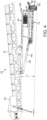
- stacker 10 may be similar to stacker 10pa except for rear support frames 28 and 30 and the mounting of those frames to conveyor 12.
- Stacker 10 therefore may include a conveyor 12, a track system 14, a wheel system 16, a hopper 20, a counterweight 22, and a pivot pad 24.
- the track system and wheel system may sometimes be referred to herein as a bogie.
- a telescoping forward support frame 26 extends from a carriage frame 34 in the same fashion as 26pa. Like forward support frame 26pa, forward support frame 26 includes a hydraulic ram drive. An upper rear support frame 28 and a lower rear support frame 30 extend rearwardly from carriage frame 34. As with stacker 10pa, a pair of upper and lower support frames are typically included, one of each pair of support frames on each lateral side of the conveyor. However, as with the discussion of stacker 10pa, this description will continue with reference being made to only one of each pair of rear support frames 28 and 30 because that is all that shows in the figures.
- both of the rear support frames 28 and 30 may be telescoping and hydraulically driven to extend and retract with internal drive cylinders 38 and 40.
- An array of aligned holes 42 and 44 may be included in frames 28 and 30, respectively.
- Pegs 46 and 48 may be provided for locking the degree of extension of rear support frames 28 and 30, respectively, once the correct degree of telescoping extension is set. While the peg and hole system is not necessary for the proper operation of stacker 10, by permitting the degree of extension to be locked, force is removed from the hydraulic system for extending and retracting the rear support frames.
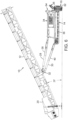
- Mounting system 32 may include a mounting plate 50 that is fixed to conveyor 12.
- the mounting plate may include a longitudinally extending slot 52 in which a pair of rollers 54 may be mounted.
- the depicted rollers 54 are rotatably mounted to a trolley 56 to which rear support frames 28 and 30 are pivotally mounted at mounting points 58 and 60.
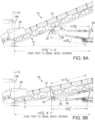
- Trolley 56 is designed to roll forwardly and rearwardly within slot 52 as the degree of elevation of conveyor 12 is increased and decreased. Specifically, when the conveyor is in its highest degree of elevation, such as shown at 27 degrees in Figures 6 and 7A , trolley 56 has slid to its forward-most position in slot 52. For stackers that are designed to be raised to even a steeper degree of elevation, the trolley would be designed to slide to its forward-most position in the slot at that highest degree of elevation. When conveyor 12 is at an intermediate degree of inclination, such as 22 degrees in Figure 8A , trolley 56 is most but not all of the way forward within slot 52. When the conveyor is at a low point of elevation, such as 7 degrees as depicted in Figures 3-5 , 6B and 7B , trolley 56 slides on rollers 54 to the rearward position within slot 52.
- mounting system 32 By including mounting system 32, the longitudinal shifting of conveyor 12 as the elevation of the conveyor is changed is eliminated; that is, instead of the entire conveyor shifting longitudinally, that shift is largely taken up in mounting system 32 and slot 52. This eliminates the need to shift the loading system, whether it be a chute or a loading conveyor. And, more importantly, this eliminates the need to shift the stacker to make sure the loading system is pouring its load into the center of hopper 20.
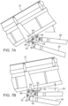
- FIGs 6A and 6B show a slight shift of the rear portion of the stacker to the left as the inclination of conveyor 12 is reduced. This is due to the rear of the stacker being elevated by a hydraulic leg 25 extending from pivot pad 24 to hopper 20. If this rearward shift presents a problem with loading hopper 20, the provision of the two hydraulically operated rear frame members 28 and 30 facilitates the retraction of those frame members to thereby draw the stacker forward or to the right in the figures. This presents a big advantage over conventional stackers that typically include two rear frame members, only one of which is hydraulically telescoping (see 28pa and 30pa in Figures 1 and 2 ). By retracting rear frame members 28 and 30 as hydraulic leg 25 is being extending, it will often be possible to keep pivot pad in its original position rather than causing it to be shifted slightly to the rear as shown in Figure 6B .
- pivot pad 24 does not need to be moved, regardless of the degree of elevation of the conveyor. This is to be distinguished from the prior art system shown in Figures 1 and 2 , in which the pivot pad 24pa often needs to be relocated as the degree of inclination of the conveyor is changed. It is common but not necessary that the hydraulic leg to pivot pad 24 be retracted in order to shorten the leg to hopper 20, as shown in Figures 8A and 8B , when the angle of elevation of the conveyor is being changed.
- FIGS 8A and 8B show a loading conveyor loading bulk material 68 being dumped into hopper 20. It should be understood, however, that any conventional loading system may be used with stacker 10 and this versatility adds to the value of the disclosed embodiment.
- Wheels 62 do not appear in these two figures but they have been identified in several of the other figures. Other figures also show other parts of stacker 10, including a hydraulic cylinder system 64 for raising and lowering wheels 62. Hydraulic cylinder system 64 typically includes hydraulic cylinders for raising and lowering wheels 62 on each lateral side of conveyor 12. Carriage frame 34 supports an engine 36, which provides hydraulic power for the entire stacker and driving power for tracks 66.
- the stacker can rotate about pivot pad 32 to create either an arc-shaped stack or a plurality of stacks arrayed in an arc.
- hydraulic cylinder system 64 raise wheels 62, tracks 66 are lowered to the ground, facilitating longitudinal as well as radial movement around the work site.
- wheels 62 are in their raised position (not shown), they can be rotated to a substantially longitudinal disposition so that when they are lowered and the tracks are thereby elevated, the stacker can is ready to be pulled down a highway without the need to load the stacker on a flatbed truck.
Landscapes
- Engineering & Computer Science (AREA)
- Mechanical Engineering (AREA)
- Framework For Endless Conveyors (AREA)
- Warehouses Or Storage Devices (AREA)
- Auxiliary Methods And Devices For Loading And Unloading (AREA)
Claims (7)
- Transportabler Kettenradialstapler (10) zum Bevorraten von Schüttgut, umfassend:einen Linearförderer (12) mit einem hinteren Bereich und einem vorderen Bereich und der dazu ausgelegt ist, Schüttgut von einer unteren Position benachbart dem hinteren Bereich zu einer angehobenen Position benachbart dem vorderen Bereich zu befördern;ein Gleiskettensystem (14), das einen Fahrgestellrahmen (34) beinhaltet, an dem der Förderer (12) montiert ist, wobei das Gleiskettensystem (14) auch ein Paar angetriebener, paralleler Gleisketten (66) beinhaltet, die dazu ausgelegt sind, wahlweise vom Boden abgehoben zu werden;ein Räderpaar (62), das an dem Fahrgestellrahmen (34) montiert ist und zwischen einer angehobenen radialen Position, in der es den Boden nicht kontaktiert, und einer ersten abgesenkten Position, in der das Räderpaar (62) radial angeordnet ist und am Boden angreift, um radiale Bewegung des Förderers (12) zu erleichtern, verlagerbar ist, wobei das Räderpaar derart schwenkbar an dem Fahrgestellrahmen (34) montiert ist, dass es in eine angehobene, im Wesentlichen längsgerichtete Position schwenken kann und in eine zweite abgesenkte Position, in der das Räderpaar im Wesentlichen längsgerichtet angeordnet ist und am Boden angreift, um längsgerichtete Bewegung des Förderers zu erleichtern, abgesenkt werden kann; undRadverlagerungsmittel (64) zum Antreiben des Räderpaars (62) aus den angehobenen Positionen in die abgesenkten Positionen, derart, dass beim Bewegen des Räderpaars in die abgesenkten Positionen das Radverlagerungsmittel die Gleisketten (66) vom Boden abhebt, um dem Förderer zu erlauben, in seitlicher oder Längsrichtung bewegt zu werden abhängig von der Position des Räderpaars;ein sich nach vorne erstreckendes, hydraulisch angetriebenes, teleskopierbares Rahmenelement (26), das sich vom Fahrgestellrahmen (34) zum vorderen Bereich des Förderers (12) zum Anheben und Absenken des Förderers erstreckt;ein Montagesystem (32), das am hinteren Bereich des Förderers befestigt ist;dadurch gekennzeichnet, dass sich ein oberes und unteres hydraulisch angetriebenes, sich nach hinten erstreckendes, teleskopierbares Rahmenelement (28, 30) zwischen dem Fahrgestellrahmen (34) und dem Montagesystem (32) erstreckt, um die Höhe des hinteren Bereichs des Förderers (12) zu steuern und dadurch eine Neigung des Förderers zu steuern, wobei das Montagesystem einen sich längsgerichtet erstreckenden Schlitz (52) definiert und einen Wagen (56) beinhaltet, der gleitfähig innerhalb des Schlitzes montiert ist, und die oberen und unteren hydraulisch angetriebenen, sich nach hinten erstreckenden, teleskopierbaren Rahmenelemente (28, 30) schwenkbar an dem Wagen montiert sind, so dass, wenn sich die oberen und unteren hydraulisch angetriebenen, sich nach hinten erstreckenden, teleskopierbaren Rahmenelemente (28, 30) teleskopierbar aus- und einfahren, der Wagen vorwärts und rückwärts in dem Schlitz gleitet, wodurch eine Tendenz des hinteren Bereichs des Förderers, sich längsgerichtet zu verschieben, wenn der Neigungsgrad des Förderers verändert wird, verringert wird, und wobei die oberen und unteren hydraulisch angetriebenen, sich nach hinten erstreckenden, teleskopierbaren Rahmenelemente (28, 30) an dem Wagen (56) an einem Paar längsgerichtet beabstandeter Montagepunkte (58, 60) montiert sind.
- Stapler nach Anspruch 1, wobei das Montagesystem (32) eine Platte (50) beinhaltet, die an dem Förderer (12) befestigt ist, und der Schlitz (52) in der Platte definiert ist.
- Stapler (10) nach Anspruch 1 oder Anspruch 2, wobei der Wagen (56) durch ein Rollenpaar (54) gleitfähig an dem Schlitz (52) montiert ist.
- Stapler (10) nach einem der Ansprüche 1 bis 3, wobei die Verringerung der Tendenz des hinteren Bereichs des Förderers (12) sich längsgerichtet zu verschieben, wenn der Neigungsgrad des Förderers verändert wird, weitgehend die Notwendigkeit beseitigt, den Stapler während des Betriebs des Staplers neu zu positionieren.
- Stapler (10) nach einem der Ansprüche 1 bis 4, ferner umfassend einen Trichter (20), der an dem hinteren Bereich des Förderers (12) positioniert ist, und eine Schwenkunterlage (24), die unterhalb des Trichters angeordnet ist und auf der der Stapler schwenkt, wenn der Förderer von einer Position in eine andere radial verschoben wird, wodurch die Verringerung der Tendenz des hinteren Bereichs des Förderers (12), sich längsgerichtet zu verschieben, wenn der Neigungsgrad des Förderers verändert wird, weitgehend die Notwendigkeit beseitigt, die Schwenkunterlage (24) während des Betriebs des Staplers neu zu positionieren.
- Stapler nach Anspruch 1, dadurch gekennzeichnet, dass durch Aus- und Einfahren der Rahmenelemente der hintere Bereich des Förderers dazu konfiguriert ist, angehoben und abgesenkt zu werden, wodurch die Neigung des Förderers verändert wird, wobei der Wagen (56), der sich längsgerichtet in dem Schlitz (52) bewegt, jegliche längsgerichtete Bewegung des Förderers aufnimmt, wenn die Neigung des Förderers verändert wird.
- Stapler nach Anspruch 6, wobei das Montagesystem (32) eine Platte (50) beinhaltet, die an der Unterseite des Förderers (12) befestigt ist, und wobei der Schlitz (52) in der Platte definiert ist, wobei die gleitfähige Montage des Wagens (56) innerhalb des Schlitzes eine Mehrzahl von Rollen (54) umfasst, die das Rückwärtsbewegen des Wagens in dem Schlitz erleichtern, wenn die Neigung des Förderers verringert wird, und das Vorwärtsbewegen, wenn die Neigung des Förderers erhöht wird.
Applications Claiming Priority (1)
| Application Number | Priority Date | Filing Date | Title |
|---|---|---|---|
| US17/030,798 US11254523B1 (en) | 2020-09-24 | 2020-09-24 | Slide mechanism for stacker |
Publications (3)
| Publication Number | Publication Date |
|---|---|
| EP3974352A1 EP3974352A1 (de) | 2022-03-30 |
| EP3974352B1 true EP3974352B1 (de) | 2024-08-21 |
| EP3974352C0 EP3974352C0 (de) | 2024-08-21 |
Family
ID=74418372
Family Applications (1)
| Application Number | Title | Priority Date | Filing Date |
|---|---|---|---|
| EP21275008.7A Active EP3974352B1 (de) | 2020-09-24 | 2021-01-28 | Stapler mit schiebemechanismus |
Country Status (6)
| Country | Link |
|---|---|
| US (1) | US11254523B1 (de) |
| EP (1) | EP3974352B1 (de) |
| CA (1) | CA3100939C (de) |
| ES (1) | ES2988086T3 (de) |
| HU (1) | HUE068966T2 (de) |
| PL (1) | PL3974352T3 (de) |
Families Citing this family (1)
| Publication number | Priority date | Publication date | Assignee | Title |
|---|---|---|---|---|
| FI129693B (en) | 2021-06-17 | 2022-06-30 | Metso Outotec Finland Oy | Arrangement, system and method for supporting an adjustable conveyor of a mobile mineral material handling station |
Family Cites Families (29)
| Publication number | Priority date | Publication date | Assignee | Title |
|---|---|---|---|---|
| US4135614A (en) | 1977-04-15 | 1979-01-23 | Assinck Bros. Limited | Portable radial stacker |
| US4345680A (en) | 1978-06-05 | 1982-08-24 | Kay Franklin J | Material transfer apparatus |
| US4538722A (en) * | 1983-03-30 | 1985-09-03 | Mcnally Pittsburg, Inc. | Conveyor shifting apparatus and process |
| JPS61201063A (ja) | 1985-02-28 | 1986-09-05 | 敷島カンバス株式会社 | 複合材強化用繊維構造体の製造方法 |
| US4813839A (en) | 1987-11-30 | 1989-03-21 | Ira Compton | Portable truck and railroad car load conveyer |
| US5390777A (en) * | 1994-02-14 | 1995-02-21 | Abco Engineering Corp. | Constant pivot mechanism for variable height radial stacking conveyors |
| US5490592A (en) * | 1994-12-05 | 1996-02-13 | Northstar Industries, Inc. | Telescoping rigid frame and scissor conveyor |
| US6129196A (en) | 1998-07-27 | 2000-10-10 | Lapper; Derek | Counterbalanced mono-fold stockpiling trailer conveyor |
| US6471031B1 (en) | 2001-01-08 | 2002-10-29 | Stanley R. Duncalf | Mobile conveyor system |
| US7223059B2 (en) | 2004-10-22 | 2007-05-29 | Construction Equipment Company | Adjustable conveyor system |
| CA2688706C (en) | 2009-12-15 | 2016-03-29 | Thor Global Enterprises Ltd. | Extendable and retractable auxilliary axle for transportable conveyor system |
| GB2478824B (en) | 2010-03-19 | 2012-06-20 | Thorkil J Johannsen | Low profile telescopic conveyor system |
| GB201009183D0 (en) | 2010-06-02 | 2010-07-14 | Telestack Ltd | Mobile Conveyor |
| US8584826B2 (en) | 2010-08-26 | 2013-11-19 | Construction Equipment Company | Conveyor systems |
| CN202108065U (zh) | 2011-06-10 | 2012-01-11 | 厦门正鸿昌机械科技有限公司 | 浮箱履带式挖掘机 |
| US8479911B2 (en) | 2011-08-22 | 2013-07-09 | Convey-AU Industries Inc. | Movable conveyor for loading a container |
| US8739956B2 (en) * | 2011-10-14 | 2014-06-03 | Construction Equipment Company | Support structure for radial conveyor |
| EP2883819B1 (de) | 2013-12-12 | 2016-10-19 | Portafill International Limited | Mobiler Lagerungsförderer |
| US10315853B2 (en) | 2015-08-10 | 2019-06-11 | Superior Industries, Inc. | Conveyor leveling systems and methods |
| CN204823276U (zh) | 2015-08-19 | 2015-12-02 | 浙江路帆机电科技有限公司 | 一种移动径向堆垛皮带机 |
| JP6451585B2 (ja) | 2015-10-13 | 2019-01-16 | トヨタ自動車株式会社 | プラグイン車両用バッテリの管理システム |
| US10017097B2 (en) | 2016-05-10 | 2018-07-10 | Ozinga Ready Mix Concrete, Inc. | Mobile transfer station for flowable material |
| US10683177B2 (en) | 2016-11-28 | 2020-06-16 | McCloskey International Limited | Radial stacker with angle control |
| US10414599B2 (en) | 2016-11-28 | 2019-09-17 | McCloskey International Limited | Tracked radial stacker with wheels |
| US10414598B2 (en) | 2016-11-28 | 2019-09-17 | McCloskey International Limited | Tracked radial stacker with wheels |
| US10011443B2 (en) | 2016-11-28 | 2018-07-03 | McCloskey International Limited | Tracked radial stacker with wheels |
| CA2985907C (en) | 2017-06-30 | 2019-05-28 | Mccloskey International Ltd. | Integral pivot/king pin for conveyor |
| US10183811B1 (en) | 2017-10-05 | 2019-01-22 | McCloskey International Limited | Stacker drive module |
| US10556752B1 (en) | 2018-11-28 | 2020-02-11 | McCloskey International Limited | Stacker with wheel assembly |
-
2020
- 2020-09-24 US US17/030,798 patent/US11254523B1/en active Active
- 2020-11-26 CA CA3100939A patent/CA3100939C/en active Active
-
2021
- 2021-01-28 ES ES21275008T patent/ES2988086T3/es active Active
- 2021-01-28 PL PL21275008.7T patent/PL3974352T3/pl unknown
- 2021-01-28 EP EP21275008.7A patent/EP3974352B1/de active Active
- 2021-01-28 HU HUE21275008A patent/HUE068966T2/hu unknown
Also Published As
| Publication number | Publication date |
|---|---|
| CA3100939A1 (en) | 2021-04-07 |
| HUE068966T2 (hu) | 2025-02-28 |
| EP3974352A1 (de) | 2022-03-30 |
| ES2988086T3 (es) | 2024-11-19 |
| EP3974352C0 (de) | 2024-08-21 |
| PL3974352T3 (pl) | 2025-01-20 |
| CA3100939C (en) | 2021-06-08 |
| US11254523B1 (en) | 2022-02-22 |
Similar Documents
| Publication | Publication Date | Title |
|---|---|---|
| EP3659949B1 (de) | Stapler mit radanordnung | |
| US10683177B2 (en) | Radial stacker with angle control | |
| CA2985905C (en) | Tracked radial stacker with wheels | |
| US10414599B2 (en) | Tracked radial stacker with wheels | |
| US10414598B2 (en) | Tracked radial stacker with wheels | |
| EP3572359B1 (de) | Radialer stapler auf schienen mit rädern | |
| EP3974352B1 (de) | Stapler mit schiebemechanismus | |
| EP3459882B1 (de) | Radialer stapler auf schienen mit rädern | |
| CA3039436C (en) | Radial stacker with angle control | |
| CA3064414C (en) | Tracked radial stacker with wheels |
Legal Events
| Date | Code | Title | Description |
|---|---|---|---|
| PUAI | Public reference made under article 153(3) epc to a published international application that has entered the european phase |
Free format text: ORIGINAL CODE: 0009012 |
|
| STAA | Information on the status of an ep patent application or granted ep patent |
Free format text: STATUS: THE APPLICATION HAS BEEN PUBLISHED |
|
| AK | Designated contracting states |
Kind code of ref document: A1 Designated state(s): AL AT BE BG CH CY CZ DE DK EE ES FI FR GB GR HR HU IE IS IT LI LT LU LV MC MK MT NL NO PL PT RO RS SE SI SK SM TR |
|
| STAA | Information on the status of an ep patent application or granted ep patent |
Free format text: STATUS: REQUEST FOR EXAMINATION WAS MADE |
|
| 17P | Request for examination filed |
Effective date: 20220404 |
|
| RBV | Designated contracting states (corrected) |
Designated state(s): AL AT BE BG CH CY CZ DE DK EE ES FI FR GB GR HR HU IE IS IT LI LT LU LV MC MK MT NL NO PL PT RO RS SE SI SK SM TR |
|
| GRAP | Despatch of communication of intention to grant a patent |
Free format text: ORIGINAL CODE: EPIDOSNIGR1 |
|
| STAA | Information on the status of an ep patent application or granted ep patent |
Free format text: STATUS: GRANT OF PATENT IS INTENDED |
|
| GRAS | Grant fee paid |
Free format text: ORIGINAL CODE: EPIDOSNIGR3 |
|
| GRAA | (expected) grant |
Free format text: ORIGINAL CODE: 0009210 |
|
| STAA | Information on the status of an ep patent application or granted ep patent |
Free format text: STATUS: THE PATENT HAS BEEN GRANTED |
|
| INTG | Intention to grant announced |
Effective date: 20240625 |
|
| AK | Designated contracting states |
Kind code of ref document: B1 Designated state(s): AL AT BE BG CH CY CZ DE DK EE ES FI FR GB GR HR HU IE IS IT LI LT LU LV MC MK MT NL NO PL PT RO RS SE SI SK SM TR |
|
| REG | Reference to a national code |
Ref country code: GB Ref legal event code: FG4D |
|
| REG | Reference to a national code |
Ref country code: CH Ref legal event code: EP |
|
| REG | Reference to a national code |
Ref country code: DE Ref legal event code: R096 Ref document number: 602021017480 Country of ref document: DE |
|
| REG | Reference to a national code |
Ref country code: IE Ref legal event code: FG4D |
|
| U01 | Request for unitary effect filed |
Effective date: 20240912 |
|
| U07 | Unitary effect registered |
Designated state(s): AT BE BG DE DK EE FI FR IT LT LU LV MT NL PT RO SE SI Effective date: 20241002 |
|
| REG | Reference to a national code |
Ref country code: ES Ref legal event code: FG2A Ref document number: 2988086 Country of ref document: ES Kind code of ref document: T3 Effective date: 20241119 |
|
| REG | Reference to a national code |
Ref country code: SK Ref legal event code: T3 Ref document number: E 45024 Country of ref document: SK |
|
| PGFP | Annual fee paid to national office [announced via postgrant information from national office to epo] |
Ref country code: NO Payment date: 20241218 Year of fee payment: 5 |
|
| PG25 | Lapsed in a contracting state [announced via postgrant information from national office to epo] |
Ref country code: GR Free format text: LAPSE BECAUSE OF FAILURE TO SUBMIT A TRANSLATION OF THE DESCRIPTION OR TO PAY THE FEE WITHIN THE PRESCRIBED TIME-LIMIT Effective date: 20241122 |
|
| PGFP | Annual fee paid to national office [announced via postgrant information from national office to epo] |
Ref country code: GB Payment date: 20241217 Year of fee payment: 5 |
|
| U20 | Renewal fee for the european patent with unitary effect paid |
Year of fee payment: 5 Effective date: 20241217 |
|
| PG25 | Lapsed in a contracting state [announced via postgrant information from national office to epo] |
Ref country code: IS Free format text: LAPSE BECAUSE OF FAILURE TO SUBMIT A TRANSLATION OF THE DESCRIPTION OR TO PAY THE FEE WITHIN THE PRESCRIBED TIME-LIMIT Effective date: 20241221 |
|
| PG25 | Lapsed in a contracting state [announced via postgrant information from national office to epo] |
Ref country code: HR Free format text: LAPSE BECAUSE OF FAILURE TO SUBMIT A TRANSLATION OF THE DESCRIPTION OR TO PAY THE FEE WITHIN THE PRESCRIBED TIME-LIMIT Effective date: 20240821 |
|
| PGFP | Annual fee paid to national office [announced via postgrant information from national office to epo] |
Ref country code: CZ Payment date: 20241217 Year of fee payment: 5 Ref country code: IE Payment date: 20241217 Year of fee payment: 5 |
|
| PGFP | Annual fee paid to national office [announced via postgrant information from national office to epo] |
Ref country code: SK Payment date: 20241220 Year of fee payment: 5 |
|
| PG25 | Lapsed in a contracting state [announced via postgrant information from national office to epo] |
Ref country code: RS Free format text: LAPSE BECAUSE OF FAILURE TO SUBMIT A TRANSLATION OF THE DESCRIPTION OR TO PAY THE FEE WITHIN THE PRESCRIBED TIME-LIMIT Effective date: 20241121 |
|
| PG25 | Lapsed in a contracting state [announced via postgrant information from national office to epo] |
Ref country code: RS Free format text: LAPSE BECAUSE OF FAILURE TO SUBMIT A TRANSLATION OF THE DESCRIPTION OR TO PAY THE FEE WITHIN THE PRESCRIBED TIME-LIMIT Effective date: 20241121 Ref country code: IS Free format text: LAPSE BECAUSE OF FAILURE TO SUBMIT A TRANSLATION OF THE DESCRIPTION OR TO PAY THE FEE WITHIN THE PRESCRIBED TIME-LIMIT Effective date: 20241221 Ref country code: HR Free format text: LAPSE BECAUSE OF FAILURE TO SUBMIT A TRANSLATION OF THE DESCRIPTION OR TO PAY THE FEE WITHIN THE PRESCRIBED TIME-LIMIT Effective date: 20240821 Ref country code: GR Free format text: LAPSE BECAUSE OF FAILURE TO SUBMIT A TRANSLATION OF THE DESCRIPTION OR TO PAY THE FEE WITHIN THE PRESCRIBED TIME-LIMIT Effective date: 20241122 |
|
| PGFP | Annual fee paid to national office [announced via postgrant information from national office to epo] |
Ref country code: HU Payment date: 20250106 Year of fee payment: 5 |
|
| REG | Reference to a national code |
Ref country code: HU Ref legal event code: AG4A Ref document number: E068966 Country of ref document: HU |
|
| PG25 | Lapsed in a contracting state [announced via postgrant information from national office to epo] |
Ref country code: SM Free format text: LAPSE BECAUSE OF FAILURE TO SUBMIT A TRANSLATION OF THE DESCRIPTION OR TO PAY THE FEE WITHIN THE PRESCRIBED TIME-LIMIT Effective date: 20240821 |
|
| PGFP | Annual fee paid to national office [announced via postgrant information from national office to epo] |
Ref country code: ES Payment date: 20250228 Year of fee payment: 5 |
|
| PGFP | Annual fee paid to national office [announced via postgrant information from national office to epo] |
Ref country code: CH Payment date: 20250201 Year of fee payment: 5 |
|
| PGFP | Annual fee paid to national office [announced via postgrant information from national office to epo] |
Ref country code: PL Payment date: 20241218 Year of fee payment: 5 |
|
| PGFP | Annual fee paid to national office [announced via postgrant information from national office to epo] |
Ref country code: TR Payment date: 20250110 Year of fee payment: 5 |
|
| PLBE | No opposition filed within time limit |
Free format text: ORIGINAL CODE: 0009261 |
|
| STAA | Information on the status of an ep patent application or granted ep patent |
Free format text: STATUS: NO OPPOSITION FILED WITHIN TIME LIMIT |
|
| 26N | No opposition filed |
Effective date: 20250522 |
|
| PG25 | Lapsed in a contracting state [announced via postgrant information from national office to epo] |
Ref country code: MC Free format text: LAPSE BECAUSE OF FAILURE TO SUBMIT A TRANSLATION OF THE DESCRIPTION OR TO PAY THE FEE WITHIN THE PRESCRIBED TIME-LIMIT Effective date: 20240821 |
|
| REG | Reference to a national code |
Ref country code: CH Ref legal event code: U11 Free format text: ST27 STATUS EVENT CODE: U-0-0-U10-U11 (AS PROVIDED BY THE NATIONAL OFFICE) Effective date: 20260201 |
|
| U20 | Renewal fee for the european patent with unitary effect paid |
Year of fee payment: 6 Effective date: 20260102 |