EP3974301A1 - Straddled vehicle - Google Patents
Straddled vehicle Download PDFInfo
- Publication number
- EP3974301A1 EP3974301A1 EP21191851.1A EP21191851A EP3974301A1 EP 3974301 A1 EP3974301 A1 EP 3974301A1 EP 21191851 A EP21191851 A EP 21191851A EP 3974301 A1 EP3974301 A1 EP 3974301A1
- Authority
- EP
- European Patent Office
- Prior art keywords
- case
- vehicle
- seat frame
- electrical components
- view
- Prior art date
- Legal status (The legal status is an assumption and is not a legal conclusion. Google has not performed a legal analysis and makes no representation as to the accuracy of the status listed.)
- Granted
Links
Images






Classifications
-
- B—PERFORMING OPERATIONS; TRANSPORTING
- B62—LAND VEHICLES FOR TRAVELLING OTHERWISE THAN ON RAILS
- B62K—CYCLES; CYCLE FRAMES; CYCLE STEERING DEVICES; RIDER-OPERATED TERMINAL CONTROLS SPECIALLY ADAPTED FOR CYCLES; CYCLE AXLE SUSPENSIONS; CYCLE SIDECARS, FORECARS, OR THE LIKE
- B62K11/00—Motorcycles, engine-assisted cycles or motor scooters with one or two wheels
- B62K11/02—Frames
- B62K11/04—Frames characterised by the engine being between front and rear wheels
-
- B—PERFORMING OPERATIONS; TRANSPORTING
- B62—LAND VEHICLES FOR TRAVELLING OTHERWISE THAN ON RAILS
- B62J—CYCLE SADDLES OR SEATS; AUXILIARY DEVICES OR ACCESSORIES SPECIALLY ADAPTED TO CYCLES AND NOT OTHERWISE PROVIDED FOR, e.g. ARTICLE CARRIERS OR CYCLE PROTECTORS
- B62J1/00—Saddles or other seats for cycles; Arrangement thereof; Component parts
- B62J1/12—Box-shaped seats; Bench-type seats, e.g. dual or twin seats
-
- B—PERFORMING OPERATIONS; TRANSPORTING
- B62—LAND VEHICLES FOR TRAVELLING OTHERWISE THAN ON RAILS
- B62J—CYCLE SADDLES OR SEATS; AUXILIARY DEVICES OR ACCESSORIES SPECIALLY ADAPTED TO CYCLES AND NOT OTHERWISE PROVIDED FOR, e.g. ARTICLE CARRIERS OR CYCLE PROTECTORS
- B62J9/00—Containers specially adapted for cycles, e.g. panniers or saddle bags
- B62J9/10—Containers specially adapted for cycles, e.g. panniers or saddle bags integrated with the cycle
- B62J9/14—Containers specially adapted for cycles, e.g. panniers or saddle bags integrated with the cycle under the saddle
-
- B—PERFORMING OPERATIONS; TRANSPORTING
- B62—LAND VEHICLES FOR TRAVELLING OTHERWISE THAN ON RAILS
- B62J—CYCLE SADDLES OR SEATS; AUXILIARY DEVICES OR ACCESSORIES SPECIALLY ADAPTED TO CYCLES AND NOT OTHERWISE PROVIDED FOR, e.g. ARTICLE CARRIERS OR CYCLE PROTECTORS
- B62J99/00—Subject matter not provided for in other groups of this subclass
-
- B—PERFORMING OPERATIONS; TRANSPORTING
- B62—LAND VEHICLES FOR TRAVELLING OTHERWISE THAN ON RAILS
- B62K—CYCLES; CYCLE FRAMES; CYCLE STEERING DEVICES; RIDER-OPERATED TERMINAL CONTROLS SPECIALLY ADAPTED FOR CYCLES; CYCLE AXLE SUSPENSIONS; CYCLE SIDECARS, FORECARS, OR THE LIKE
- B62K19/00—Cycle frames
- B62K19/30—Frame parts shaped to receive other cycle parts or accessories
Definitions
- the present invention relates generally to a straddled vehicle, and in particular, though not exclusively, to a straddled vehicle having cases for storing electrical components.
- the straddled vehicle (1) includes a right seat frame (21R), a left seat frame (21L), seats (7, 9), a case (40), and a battery (60).
- the case (40) is disposed leftward of the right seat frame (21R), rightward of the left seat frame (21L), and below the seats (7, 9).
- the case (40) is formed integral.
- the battery (60) is stored in the case (40).
- a battery is one of the electrical components.
- the number of electrical components mounted on a straddled vehicle has been on the increase. This has required an increase in the cost of designing an arrangement of each electrical component. Further, the case for storing each electrical component has increased in size. This has increased the case manufacturing cost.
- This invention has been made having regard to the state of the art noted above, and its object is to provide a straddled vehicle that allows efficient designing of an arrangement of electrical components, and curbing of the manufacturing cost of cases for storing the electrical components.
- Different types of straddled vehicles may have seat frames of different lengths in the vehicle's longitudinal direction.
- the case is disposed between a right seat frame and a left seat frame.
- the case therefore, has shapes different between different types of straddled vehicles having seat frames of different lengths. Consequently, plural types of cases having different shapes are prepared, respectively, for the plural types of straddled vehicles having the seat frames of different lengths.
- plural types of forming dies are manufactured for the plural types of cases, respectively. Further, the plural types of cases are manufactured using the respective forming dies.
- each electrical component stored in the case is different between the plural types of cases having different shapes.
- the arrangement of each electrical component is designed for each case having a different shape.
- the Inventor herein has studied how to curb the cost of manufacturing plural types of cases having different shapes. Further, based on the above findings, the Inventor has studied how to realize labor-saving in the operation to design an arrangement of electrical components for each type of case.
- the straddled vehicle may comprise one or more of:
- the first electrical components may comprise one or more of:
- the second electrical components may comprise a first connector for connecting wiring of a taillight.
- the second case may be smaller in volume than the first case.
- the straddled vehicle may comprise a first case and a second case.
- the first case and second case may be arranged leftward of the right seat frame, rightward of the left seat frame, and below the seat, respectively.
- the second case may be located behind the first case.
- the second case may be an element separate from the first case. Consequently, the length in the vehicle's longitudinal direction of the entirety of the first case and second case may be changed easily by changing the shape of the second case without changing the shape of the first case.
- "changing the shape of the second case” may be, for example, preparing plural types of second cases different in shape and switching between the plural types of second cases.
- the first case and second case may be easily applicable to plural types of straddled vehicles with the right seat frame and left seat frame having different lengths in the vehicle's longitudinal direction.
- the first case having the same shape may be easily applicable to plural types of straddled vehicles with the right seat frame and left seat frame having different lengths in the vehicle's longitudinal direction. That is, the first case may be easily shared between plural types of straddled vehicles with the right seat frame and left seat frame having different lengths in the vehicle's longitudinal direction.
- the manufacturing cost of the first case may be reduced effectively.
- the volume of the second case may be smaller than the volume of the first case. So, even when plural types of second cases different in shape are prepared, the manufacturing cost of the second cases may be kept down not to become excessively high. Thus, by changing the shape of the second case, without changing the shape of the first case, the overall manufacturing cost of the first case and second case may be conveniently kept down.
- the first case may store a plurality of first electrical components.
- the second case may store a plurality of second electrical components. Consequently, when changing the shape of the second case, without changing the shape of the first case, it may be sufficient to design only an arrangement of the second electrical components. This may enable an effective reduction of the cost of designing the arrangement of the first electrical components.
- the volume of the second case may be smaller than the volume of the first case. Even when the shape of the second case is changed, the arrangement of the second electrical components may be designed easily. Thus, by changing the shape of the second case, without changing the shape of the first case, the overall arrangement of the first electrical components and second electrical components may be efficiently designed.
- the first electrical components may comprise a battery and a hydraulic unit.
- the battery and hydraulic unit may be stored in the first case.
- the shape of the battery cannot change easily between plural types of straddled vehicles.
- the shape of the hydraulic unit cannot change easily between plural types of straddled vehicles. Consequently, the cost of designing an arrangement of the battery and hydraulic unit may be reduced with increased effect.
- the second electrical components may comprise a first connector.
- the first connector may be stored in the second case.
- the arrangement of the first connector may therefore be designed easily.
- the shape of the first connector may be easily changeable between plural types of straddled vehicles.
- the arrangement of the first connector may be designed flexibly according to various shapes of the first connector. This may enable an efficient designing of the arrangement of the battery, and/or hydraulic unit, and/or first connector.
- the manufacturing cost of the first case and second case may be held down. Further, the arrangement of the first electrical components and second electrical components may be designed efficiently.
- the manufacturing cost of the first case and second case may be further held down, and the arrangement of the first electrical components and second electrical components may be designed with increased efficiency.
- the second case may have a length in a vehicle's up-down direction smaller than a length in the vehicle's up-down direction of the first case.
- the second case has a length in the vehicle's longitudinal direction corresponding to or smaller than a length in the vehicle's longitudinal direction of the first case.
- the battery and the hydraulic unit are arranged to align in the vehicle's longitudinal direction in the plan view of the vehicle.
- the first case may conveniently prevent the length in a vehicle's transverse direction of the first case from becoming excessively large.
- the first case may therefore easily be located leftward of the right seat frame and rightward of the left seat frame. Further, the length in the vehicle's up-down direction of the first case may conveniently be prevented from becoming excessively large. The first case may therefore easily be located below the seat.
- the first case may comprise one or more of;
- the first case may be divided into the front portion, middle portion, and rear portion.
- the battery may be stored in the middle portion.
- the depth of the middle portion may be larger than the depth of the front portion and/or the depth of the rear portion. Therefore, even when the battery is relatively large, the middle portion may conveniently store the battery.
- the above straddled vehicle may comprise a bracket disposed below the first case and in contact with the first case.
- the bracket may overlap the battery in the plan view of the vehicle.
- the bracket may be located below the first case.
- the bracket may contact the first case.
- the bracket may receive the load of the first case.
- the bracket may be located below the battery.
- the bracket may overlap the battery in the plan view of the vehicle. Consequently, the bracket may conveniently receive the load of the battery.
- the first electrical components may further comprise:
- the first electrical components may comprise steel pipes and/or a joint member.
- the steel pipes and/or joint member may be stored in the first case.
- the shapes of the steel pipes cannot easily change between plural types of straddled vehicles.
- the shape of the joint member cannot easily change between plural types of straddled vehicles. Consequently, the cost of designing an arrangement of the steel pipes and joint member may be reduced with increased effect.
- the second electrical components may further comprise:
- the second electrical components may comprise a second connector and/or a third connector.
- the second connector and/or third connector may be stored in the second case.
- the arrangement of the second connector and/or third connector may therefore be designed easily.
- the shape of the second connector may be easily changeable between plural types of straddled vehicles.
- the shape of the third connector may be easily changeable between plural types of straddled vehicles. Consequently, the arrangement of the second connector may be designed flexibly according to various shapes of the second connector.
- the arrangement of the third connector may be designed flexibly according to various shapes of the third connector.
- the first electrical components may be larger in number than the second electrical components.
- the number of first electrical components may be larger than the number of second electrical components. Therefore, when changing the shape of the second case without changing the shape of the first case, the cost of designing the arrangement of the first electrical components may be reduced with increased effect.
- the number of second electrical components may be smaller than the number of first electrical components. Therefore, even when the shape of the second case is changed, the arrangement of the second electrical components may be designed with increased ease. Consequently, by changing the shape of the second case without changing the shape of the first case, the arrangement of the entirety of the first electrical components and second electrical components may be designed with increased efficiency.
- the first case in a side view of the vehicle, may extend rearward from a front end of the right seat frame and a front end of the left seat frame.
- the first case having the same shape may easily be installed relative to plural types of right seat frames and left seat frames having different lengths.
- the first case may easily be shared between plural types of straddled vehicles with right seat frames and left seat frames having different lengths.
- the first case may comprise:
- the second right mounting seat may be located more rearward than the first right mounting seat. Consequently, the position of the right seat frame connected to the second case may be different from the position of the right seat frame connected to the first case.
- the second left mounting seat may be located more rearward than the first left mounting seat. Consequently, the position of the left seat frame connected to the second case may be different from the position of the left seat frame connected to the first case. Therefore, even when the shape of the second case is changed, the right seat frame and left seat frame may conveniently support the first case and second case.
- first right mounting seat and/or the second right mounting seat may be located above the right seat frame, respectively; and/or the first left mounting seat and/or the second left mounting seat may be located above the left seat frame, respectively.
- the right seat frame and left seat frame may support the first case and second case with increased convenience.
- the first case and the second case may be separably connected to each other.
- the first electrical components and second electrical components may be installed in positions close to each other.
- a straddled vehicle according to several embodiments of the present invention will be described below with reference to the accompanying drawings.
- a street type vehicle will be described as one example of the straddled vehicle.
- Fig. 1 is a left side view of a straddled vehicle 1 according to a first embodiment.
- the straddled vehicle 1 is, for example, a street type vehicle.
- Fig. 1 shows a longitudinal direction X, a transverse direction Y, and an up-down direction Z of the straddled vehicle 1.
- the longitudinal direction X, transverse direction Y, and up-down direction Z are defined with reference to a driver mounted on the straddled vehicle 1.
- the longitudinal direction X, transverse direction Y, and up-down direction Z are perpendicular to one another.
- the longitudinal direction X and transverse direction Y are horizontal.
- the up-down direction Z is vertical.
- forward and “rearward” include not only directions parallel to the longitudinal direction X but also directions approximate to the longitudinal direction X.
- the directions approximate to the longitudinal direction X are, for example, directions at angles not exceeding 45 degrees to the longitudinal direction X.
- “rightward” and “leftward” include not only directions parallel to the transverse direction Y but also directions approximate to the transverse direction Y.
- upward and “downward” include not only directions parallel to the up-down direction Z but also directions approximate to the up-down direction Z.
- the drawings show front, rear, up, down, right, and left, as appropriate.
- Member Ma is located more rightward/leftward than Member Mb," defines a position in the transverse direction Y of Member Ma relative to Member Mb, and does not define a position in the longitudinal direction X or the up-down direction Z of Member Ma relative to Member Mb.
- Member Ma may, or may not, overlap Member Mb in a side view of the vehicle.
- Member Ma is located rightward/leftward of Member Mb," without reference to a looking direction defines a position in the transverse direction Y of Member Ma relative to Member Mb, a position in the longitudinal direction X of Member Ma relative to Member Mb, and a position in the up-down direction Z of Member Ma relative to Member Mb.
- This expression means that Member Ma is located more rightward/leftward than Member Mb, and that at least part of Member Ma overlaps at least part of Member Mb in a side view of the vehicle.
- Member Ma is located rightward/leftward of Member Mb in a plan view of the vehicle.
- This expression means that Member Ma is located more rightward/leftward than Member Mb, and that the front end of Member Ma is located more forward than the rear end of Member Mb, and that the rear end of Member Ma is located more rearward than the front end of Member Mb.
- Member Ma is located rightward/leftward of Member Mb in a front view of the vehicle.
- This expression means that Member Ma is located more rightward/leftward than Member Mb, the upper end of Member Ma is located higher than the lower end of Member Mb, and the lower end of Member Ma is located lower than the upper end of Member Mb.
- the straddled vehicle 1 comprises a body frame 2.
- the body frame 2 has a main frame 3.
- the main frame 3 extends from front to rear of the body frame 2. More particularly, the main frame 3 extends rearward and downward in a side view of the vehicle.
- the straddled vehicle 1 comprises a steering device 11.
- the steering device 11 is supported by the front of the body frame 2.
- the steering device 11 is rotatable relative to the body frame 2.
- the steering device 11 has a handlebar 12, a front suspension 13, and a front axle 14.
- the handlebar 12 is disposed in an upper portion of the steering device 11.
- the front suspension 13 extends forward and downward from the handlebar 12.
- the front axle 14 is disposed in a lower portion of the steering device 11.
- the front axle 14 is supported by the front suspension 13.
- the straddled vehicle 1 comprises a front wheel 15.
- the front wheel 15 is supported by the steering device 11.
- the front wheel 15 is supported by the front axle 14.
- the front wheel 15 is rotatable about the front axle 14.
- the straddled vehicle 1 comprises an engine 17. At least part of the engine 17 is located below the main frame 3 in the side view of the vehicle.
- the engine 17 is supported by the body frame 2.
- the engine 17 is supported by the main frame 3.
- the engine 17 is fixed to the body frame 2.
- the engine 17 is not swingable relative to the body frame 2.
- the straddled vehicle 1 comprises a fuel tank 18.
- the fuel tank 18 is located above the engine 17 in the side view of the vehicle. At least part of the fuel tank 18 is located above the main frame 3 in the side view of the vehicle.
- the fuel tank 18 is supported by the body frame 2.
- the straddled vehicle 1 comprises a seat 20.
- the seat 20 is located behind the fuel tank 18.
- the whole seat 20 is located lower than an upper end of the fuel tank 18.
- Part of the seat 20 is located in the same height position as the fuel tank 18 in the side view of the vehicle.
- the seat 20 is located more rearward and higher than the engine 17.
- the seat 20 is supported by the body frame 2.
- the seat 20 has a front seat 21 and a rear seat 22.
- the rear seat 22 is located behind the front seat 21.
- the rear seat 22 is an element separate from the front seat 21.
- the front seat 21 and rear seat 22 are separable from each other.
- the straddled vehicle 1 comprises a side cover 23.
- the side cover 23 is located below the seat 20 in the side view of the vehicle.
- the straddled vehicle 1 comprises a mudguard 24.
- the mudguard 24 extends rearward and downward from the side cover 23 in the side view of the vehicle.
- the straddled vehicle 1 comprises a taillight 25, a rear flasher light 26, and a license light 29.
- the taillight 25 is located behind the side cover 23 in the side view of the vehicle.
- the rear flasher light 26 and license light 29 are attached to the mudguard 24.
- the rear flasher light 26 emits light for notifying third parties of course changes and the like of the straddled vehicle 1.
- the rear flasher light 26 has a left rear flasher light 28 and a right rear flasher light not shown.
- the license light 29 emits light for illuminating the license plate not shown.
- the straddled vehicle 1 comprises a pivot shaft 30, a swing arm 31, a rear axle 32, and a rear wheel 33.
- the pivot shaft 30 is located behind the engine 17 in the side view of the vehicle.
- the pivot shaft 30 is located lower than the fuel tank 18 and seat 20.
- the pivot shaft 30 is supported by the body frame 2.
- the swing arm 31 is supported by the pivot shaft 30.
- the swing arm 31 extends rearward from the pivot shaft 30.
- the swing arm 31 is swingable about the pivot shaft 30.
- the rear axle 32 is supported by a rear portion of the swing arm 31.
- the rear wheel 33 is supported by the rear axle 32.
- the rear wheel 33 is rotatable about the rear axle 32.
- the rear wheel 33 is located below the seat 20 in the side view of the vehicle.
- the straddled vehicle 1 comprises a chain 34.
- the chain 34 connects to the rear wheel 33.
- the chain 34 transmits power outputted from the engine 17 to the rear wheel 33.
- the rear wheel 33 is rotated about the rear axle 32 by the power transmitted from the chain 34.
- the driver sits straddling the front seat 21, and puts on a knee grip.
- the knee grip is a holding of part of the straddled vehicle 1 between the legs of the driver.
- the part of the straddled vehicle 1 is at least part of the main frame 3 and fuel tank 18, for example.
- the driver of the straddled vehicle 1 grasps the handlebar 12 and controls the steering device 11.
- a passenger of the straddled vehicle 1 sits on the rear seat 22.
- Fig. 2 is a plan view of a rear portion of the straddled vehicle 1.
- Fig. 2 shows a vehicle center plane C.
- the vehicle center plane C is an imaginary plane perpendicular to the transverse direction Y.
- the vehicle center plane C passes through the center of the straddled vehicle 1.
- Fig. 2 shows the seat 20 in two-dot chain lines. Fig. 2 omits the side cover 23 and other elements.
- the body frame 2 has a right seat frame 4 and a left seat frame 5.
- the right seat frame 4 extends in the longitudinal direction X in the plan view of the vehicle.
- the left seat frame 5 is located leftward of the right seat frame 4.
- the left seat frame 5 extends in the longitudinal direction X in the plan view of the vehicle.
- the right seat frame 4 is located rightward of the vehicle center plane C.
- the left seat frame 5 is located leftward of the vehicle center plane C.
- the right seat frame 4 has a front end 4f and a rear end 4r.
- the left seat frame 5 has a front end 5f and a rear end 5r.
- the front ends 4f and 5f are connected to the main frame 3, respectively.
- Fig. 2 shows a length Lf.
- the length Lf is a length in the longitudinal direction X of the right seat frame 4 and left seat frame 5. More particularly, the length Lf is a distance in the longitudinal direction X between the front ends 4f and 5f and the rear ends 4r and 5r.
- the body frame 2 has a right backstay 6 and a left backstay 7.
- the right backstay 6 extends in the longitudinal direction X in the plan view of the vehicle.
- the left backstay 7 is located leftward of the right backstay 6.
- the left backstay 7 extends in the longitudinal direction X in the plan view of the vehicle.
- the right backstay 6 is located rightward of the vehicle center plane C.
- the left backstay 7 is located leftward of the vehicle center plane C.
- the right backstay 6 has a front end 6f and a rear end 6r.
- the left backstay 7 has a front end 7f and a rear end 7r.
- the front ends 6f and 7f are connected to the main frame 3, respectively.
- the rear end 6r is connected to the right seat frame 4.
- the rear end 7r is connected to the left seat frame 5.
- the body frame 2 has a bracket 8.
- the bracket 8 is supported by the right backstay 6 and left backstay 7.
- the bracket 8 extends in the transverse direction Y.
- the bracket 8 is located more rearward than the front ends 4f and 5f.
- the bracket 8 is located more rearward than the front ends 6f and 7f.
- the bracket 8 is located more forward than the rear ends 4r and 5r.
- the bracket 8 is located more forward than the rear ends 6r and 7r.
- the bracket 8 has a plate portion 9 and two mounting seats 10.
- the plate portion 9 has a substantially flat plate shape. At least part of the plate portion 9 is, in the plan view of the vehicle, located leftward of the right seat frame 4 and rightward of the left seat frame 5.
- Each mounting seat 10 is, in the plan view of the vehicle, also located leftward of the right seat frame 4 and rightward of the left seat frame 5.
- Each mounting seat 10 is connected to the plate portion 9.
- the seat 20 is located above the right seat frame 4 and left seat frame 5.
- the seat 20 overlaps the right seat frame 4 and left seat frame 5 in the plan view of the vehicle.
- the seat 20 is located above the right backstay 6 and left backstay 7.
- the seat 20 overlaps the right backstay 6 and left backstay 7 in the plan view of the vehicle.
- the seat 20 is located above the bracket 8.
- the seat 20 overlaps the bracket 8 in the plan view of the vehicle.
- Fig. 3 is a left side view of the rear portion of the straddled vehicle 1.
- Fig. 3 shows the seat 20 in two-dot chain lines.
- Fig. 3 omits the side cover 23 and other elements.
- the left seat frame 5 extends rearward and upward in the side view of the vehicle.
- the right seat frame 4 overlaps the left seat frame 5 in the side view of the vehicle. Though not shown, the right seat frame 4 also extends rearward and upward in the side view of the vehicle.
- the left backstay 7 is located below the left seat frame 5 in the side view of the vehicle.
- the left backstay 7 extends rearward and upward in the side view of the vehicle.
- the right backstay 6 overlaps the left backstay 7 in the side view of the vehicle.
- the right backstay 6 is also located below the right seat frame 4 in the side view of the vehicle.
- the right backstay 6 also extends rearward and upward in the side view of the vehicle.
- the bracket 8 is located below the right seat frame 4 and left seat frame 5 in the side view of the vehicle.
- the seat 20 is located above the right seat frame 4 and left seat frame 5 in the side view of the vehicle.
- the right seat frame 4 and left seat frame 5 are located above the rear wheel 33 in the side view of the vehicle.
- the right backstay 6 and left backstay 7 are located above the rear wheel 33 in the side view of the vehicle.
- the bracket 8 is located above the rear wheel 33 in the side view of the vehicle.
- the straddled vehicle 1 comprises a first case 41.
- the first case 41 extends rearward from the front end 5f of the left seat frame 5 in the side view of the vehicle.
- the first case 41 overlaps the front end 5f of the left seat frame 5 in the side view of the vehicle.
- the first case 41 extends rearward from the front end 4f of the right seat frame 4 in the side view of the vehicle.
- the first case 41 overlaps the front end 4f of the right seat frame 4 in the side view of the vehicle.
- the first case 41 overlaps the left seat frame 5 and left backstay 7 in the side view of the vehicle. Most part of the first case 41 is located below the left seat frame 5 and above the left backstay 7 in the side view of the vehicle.
- the straddled vehicle 1 comprises a second case 61.
- the second case 61 is located behind the first case 41.
- the second case 61 overlaps the left seat frame 5 and left backstay 7 in the side view of the vehicle. Most part of the second case 61 is located below the left seat frame 5 and above the left backstay 7 in the side view of the vehicle.
- the first case 41 and second case 61 are located below the seat 20 in the side view of the vehicle.
- first case 41 and second case 61 are located above the rear wheel 33 in the side view of the vehicle.
- Fig. 4 is a plan view of the rear portion of the straddled vehicle 1.
- Fig. 4 shows the first case 41 and second case 61.
- Fig. 4 shows the seat 20 in two-dot chain lines.
- Fig. 4 omits the side cover 23 and other elements.
- the first case 41 is located leftward of the right seat frame 4, rightward of the left seat frame 5, and below the seat 20.
- the second case 61 is located leftward of the right seat frame 4, rightward of the left seat frame 5, below the seat 20, and behind the first case 41.
- the first case 41 is located leftward of the right backstay 6 and rightward of the left backstay 7.
- the second case 61 is located leftward of the right backstay 6 and rightward of the left backstay 7.
- the first case 41 is located above the bracket 8.
- the first case 41 overlaps the bracket 8 in the plan view of the vehicle.
- the second case 61 is located more rearward than the bracket 8. The second case 61 does not overlap the bracket 8 in the plan view of the vehicle.
- the first case 41 and second case 61 overlap the seat 20 in the plan view of the vehicle.
- the first case 41 has a front end 41f.
- the front end 41f is, with respect to the longitudinal direction X, located in a position corresponding to the front ends 4f and 5f or more forward than the front ends 4f and 5f.
- Fig. 4 shows a length Lc.
- the length Lc is an entire length in the longitudinal direction X of the first case 41 and second case 61. More particularly, the length Lc is a distance in the longitudinal direction X between the front end 41f of the first case 41 and a rear end 61r of the second case 61. The length Lc is smaller than the length Lf.
- the first case 41 is supported by the right seat frame 4 and left seat frame 5.
- the first case 41 has a first right mounting seat 42 and a first left mounting seat 43.
- the first right mounting seat 42 is located above the right seat frame 4.
- the first right mounting seat 42 is connected to the right seat frame 4.
- the first left mounting seat 43 is located above the left seat frame 5.
- the first left mounting seat 43 is connected to the left seat frame 5.
- the first case 41 is further supported by the bracket 8.
- the bracket 8 is located below the first case 41.
- the bracket 8 contacts the first case 41.
- the bracket 8 directly contacts the first case 41.
- the bracket 8 receives the load of the first case 41.
- the bracket 8 is further connected to the first case 41.
- the plate portion 9 is located below the first case 41.
- the plate portion 9 contacts the first case 41.
- the plate portion 9 receives the load of the first case 41.
- the mounting seat 10 is located below the first case 41.
- the mounting seat 10 is connected to the first case 41.
- the second case 61 is supported by the right seat frame 4 and left seat frame 5.
- the second case 61 has a second right mounting seat 62 and a second left mounting seat 63.
- the second right mounting seat 62 is located more rearward than the first right mounting seat 42.
- the second right mounting seat 62 is located above the right seat frame 4.
- the second right mounting seat 62 is connected to the right seat frame 4.
- the second left mounting seat 63 is located more rearward than the first left mounting seat 43.
- the second left mounting seat 63 is located above the left seat frame 5.
- the second left mounting seat 63 is connected to the left seat frame 5.
- Fig. 2 shows positions 4j and 4k of the right seat frame 4.
- the right seat frame 4 is, in the position 4j, connected to the first right mounting seat 42.
- the right seat frame 4 is, in the position 4k, connected to the second right mounting seat 62.
- the position 4k is located more rearward than the position 4j.
- Fig. 2 shows positions 5j and 5k of the left seat frame 5.
- the left seat frame 5 is, in the position 5j, connected to the first left mounting seat 43.
- the left seat frame 5 is, in the position 5k, connected to the second left mounting seat 63.
- the position 5k is located more rearward than the position 5j.
- the straddled vehicle 1 comprises fastening members 58 and 68.
- the fastening member 58 fastens the left seat frame 5 and first left mounting seat 43.
- the fastening member 68 fastens the left seat frame 5 and second left mounting seat 63.
- the fastening members 58 and 68 are bolts, for example.
- the straddled vehicle 1 comprises a plurality of first electrical components 70.
- the first electrical components 70 are stored in the first case 41. All the first electrical components 70 are stored in the first case 41. All the first electrical components 70 overlap the first case 41 in the plan view of the vehicle.
- the first electrical components 70 comprise a battery 71.
- the battery 71 is stored in the first case 41.
- the whole battery 71 overlaps the first case 41 in the plan view.
- the first electrical components 70 other than the battery 71 are similarly located relative to the first case 41.
- the battery 71 is located above the bracket 8.
- the battery 71 overlaps the bracket 8 in the plan view of the vehicle. At least part of the battery 71 overlaps the bracket 8 in the plan view of the vehicle.
- the battery 71 is located above the plate portion 9.
- the battery 71 overlaps the plate portion 9 in the plan view of the vehicle.
- the first electrical components 70 comprise a hydraulic unit 72.
- the battery 71 and hydraulic unit 72 are arranged along the longitudinal direction X.
- the hydraulic unit 72 is located in front of the battery 71 in the plan view of the vehicle.
- the hydraulic unit 72 adjusts the hydraulic pressure of brake fluid.
- the straddled vehicle 1 comprises a front brake mechanism (not shown) for braking the front wheel 15 and a rear brake mechanism (not shown) for braking the rear wheel 33.
- the hydraulic unit 72 is connected to at least one of the front brake mechanism and rear brake mechanism.
- the hydraulic unit 72 adjusts the hydraulic pressure of the brake fluid of the front brake mechanism to suppress the lock tendency of the front wheel 15.
- the hydraulic unit 72 adjusts the hydraulic pressure of the brake fluid of the rear brake mechanism to suppress the lock tendency of the rear wheel 33.
- the first electrical components 70 comprise steel pipes 73.
- the steel pipes 73 are connected to the hydraulic unit 72.
- the steel pipes 73 do not have flexibility.
- the first electrical components 70 comprise a joint member 74.
- the joint member 74 is connected to the steel pipes 73.
- the joint member 74 is located in front of the hydraulic unit 72 in the plan view of the vehicle.
- the straddled vehicle comprises flexible tubes 89.
- the flexible tubes 89 are connected to the joint member 74.
- the flexible tubes 89 have flexibility.
- the joint member 74 joins the steel pipes 73 and flexible tubes 89.
- the flexible tubes 89 are rubber tubes, for example.
- the flexible tubes 89 are not the first electrical components 70. This is because at least parts of the flexible tubes 89 are located outside the first case 41.
- the first electrical components 70 comprise a main relay 75.
- the main relay 75 is located leftward of the joint member 74 in the plan view of the vehicle, for example.
- the first electrical components 70 comprise a fan relay 76.
- the fan relay 76 is located leftward of the hydraulic unit 72 in the plan view of the vehicle, for example.
- the first electrical components 70 comprise a fuse box 77.
- the fuse box 77 is located behind the battery 71 in the plan view of the vehicle, for example.
- the first electrical components 70 comprise a stop lamp relay 78.
- the stop lamp relay 78 is located behind the fuse box 77 in the plan view of the vehicle, for example.
- the first electrical components 70 comprise a starter relay 79.
- the starter relay 79 is located leftward of the fuse box 77 in the plan view of the vehicle, for example.
- the first electrical components 70 comprise an inertial measurement unit 80.
- the inertial measurement unit 80 overlaps the battery 71 in the plan view of the vehicle.
- the inertial measurement unit 80 is located below the battery 71, for example.
- the number of first electrical components 70 is ten, for example.
- the battery 71 is large compared with the first electrical components 70 other than the battery 71.
- the straddled vehicle 1 comprises a plurality of second electrical components 90.
- the second electrical components 90 are stored in the second case 61. All the second electrical components 90 are stored in the second case 61. All the second electrical components 90 overlap the second case 61 in the plan view of the vehicle.
- the second electrical components 90 comprise a first connector 91.
- the first connector 91 connects wiring of the taillight 25.
- the first connector 91 is stored in the second case 61.
- the whole first connector 91 overlaps the second case 61 in the plan view.
- the second electrical components 90 other than the first connector 91 are similarly located relative to the second case 61.
- the second electrical components 90 comprise a second connector 92.
- the second connector 92 connects wiring of the rear flasher light 26.
- the second connector 92 is located in front of the first connector 91 in the plan view of the vehicle.
- the second connector 92 comprises a second right connector 93 and a second left connector 94.
- the second right connector 93 connects wiring of the right rear flasher light.
- the second left connector 94 connects wiring of the left rear flasher light 28.
- the second right connector 93 and second left connector 94 are arranged to align in the transverse direction Y in the plan view of the vehicle.
- the second electrical components 90 comprise a third connector 95.
- the third connector 95 connects wiring of the license light 29.
- the third connector 95 is located in front of the first connector 91 in the plan view of the vehicle.
- the third connector 95 is located behind the second connector 92 in the plan view of the vehicle.
- the second electrical components 90 comprise an on-board diagnostics 96.
- the on-board diagnostics 96 is located more rearward and more leftward than the first connector 91.
- the second electrical components 90 comprise a heater relay 97.
- the heater relay 97 is located leftward of the second connector 92 in the plan view of the vehicle.
- the second electrical components 90 comprise a seat heater switch 98.
- the seat heater switch 98 is located leftward of the heater relay 97 in the plan view of the vehicle.
- the number of second electrical components 90 is seven, for example.
- the number of second electrical components 90 is smaller than the number of first electrical components 70.
- Fig. 5 is a perspective view of the first case 41 and second case 61.
- the volume of the first case 41 is larger than the volume of the second case 61.
- the first case 41 has a first bottom 44, a first right wall 45, and a first left wall 46.
- the second case 61 has a second bottom 64, a second right wall 65, and a second left wall 66.
- the volume of the first case 41 corresponds to the volume of a space demarcated by the first bottom 44, first right wall 45, and first left wall 46.
- the volume of the second case 61 corresponds to the volume of a space demarcated by the second bottom 64, second right wall 65, and second left wall 66.
- the second bottom 64 is continuous with the first bottom 44.
- the second right wall 65 is continuous with the first right wall 45.
- the second left wall 66 is continuous with the first left wall 46.
- the second case 61 is an element separate from the first case 41.
- the first case 41 is formed integral.
- the first case 41 is inseparable into a plurality of members.
- the second case 61 is formed integral.
- the second case 61 is inseparable into a plurality of members.
- the first case 41 is made of synthetic resin, for example.
- the second case 61 is made of synthetic resin, for example.
- the first case 41 and second case 61 are formed separately.
- the first case 41 and second case 61 are formed using forming dies, respectively.
- the forming die for forming the second case 61 is different from the forming die for forming the first case 41.
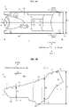
- Fig. 6A is a plan view of the first case 41.
- the first case 41 has a substantially rectangular shape in the plan view of the vehicle.
- the first bottom 44 crosses the vehicle center plane C in the plan view of the vehicle.
- the first bottom 44 extends in the longitudinal direction X and transverse direction Y in the plan view of the vehicle.
- the first right wall 45 is located rightward of the vehicle center plane C in the plan view of the vehicle.
- the first right wall 45 is located on a right edge of the first bottom 44 in the plan view of the vehicle.
- the first right wall 45 is connected to the first bottom 44.
- the first right wall 45 extends upward from the first bottom 44.
- the first right wall 45 extends in the longitudinal direction X in the plan view of the vehicle.
- the first left wall 46 is located leftward of the first right wall 45.
- the first left wall 46 is located leftward of the vehicle center plane C in the plan view of the vehicle.
- the first left wall 46 is located on a left edge of the first bottom 44.
- the first left wall 46 is connected to the first bottom 44.
- the first left wall 46 extends upward from the first bottom 44.
- the first left wall 46 extends in the longitudinal direction X in the plan view of the vehicle.
- the first right mounting seat 42 is connected to the first right wall 45.
- the first right mounting seat 42 extends rightward from the first right wall 45.
- the first left mounting seat 43 is connected to the first left wall 46.
- the first left mounting seat 43 extends leftward from the first left wall 46.
- the first right wall 45 is located leftward of the right seat frame 4 in the plan view of the vehicle.
- the first left wall 46 is located rightward of the left seat frame 5 in the plan view of the vehicle.
- Fig. 6A shows a length L1 and a width W1.
- the length L1 is a length of the first case 41 in the longitudinal direction X. More particularly, the length L1 is a distance in the longitudinal direction X between the front end 41f of the first case 41 and the rear end 41r of the first case 41.
- the width W1 is a length of the first case 41 in the transverse direction Y. More particularly, the width W1 is a distance in the transverse direction Y between the first right wall 45 and first left wall 46.
- the length L1 is smaller than the length Lc.
- the length L1 is larger than the width W1.
- the width W1 is slightly smaller than a separation distance in the transverse direction Y between the right seat frame 4 and left seat frame 5.
- Fig. 6B is a side view of the first case 41.
- the first case 41 has an upper edge 47 and a lower edge 48 in the side view of the vehicle.
- the upper edge 47 corresponds to an upper edge of the first left wall 46, for example.
- the upper edge 47 extends rearward and upward in the side view of the vehicle.
- the lower edge 48 corresponds to a lower edge of the first left wall 46, for example.
- the lower edge 48 corresponds to the first bottom 44, for example.
- the lower edge 48 is curved to bulge downward.
- the lower edge 48 comprises, in the side view of the vehicle, portions extending rearward and downward, and portions extending rearward and upward.
- the first case 41 is divided into a front portion 51, a middle portion 52, and a rear portion 53.
- the front portion 51, the middle portion 52, and the rear portion 53 are integrally formed.
- the front portion 51, the middle portion 52, and the rear portion 53 are inseparable from one another.
- Fig. 6B exemplifies boundary lines K1 and K2.
- the boundary line K1 is an imaginary line schematically showing a boundary between the front portion 51 and middle portion 52.
- the boundary line K2 is an imaginary line schematically showing a boundary between the middle portion 52 and rear portion 53.
- the middle portion 52 is located behind the front portion 51.
- the rear portion 53 is located behind the middle portion 52.
- Fig. 6B shows a depth D1 of the front portion 51, a depth D2 of the middle portion 52, and a depth D3 of the rear portion 53.
- the depth D1 is a length on an imaginary line J1 of the front portion 51.
- the depth D2 is a length on an imaginary line J2 of the middle portion 52.
- the depth D3 is a length on an imaginary line J3 of the rear portion 53.
- the imaginary lines J1, J2, and J3 are parallel to the up-down direction Z, respectively.
- the imaginary line J1 crosses the front portion 51 in the side view of the vehicle.
- the imaginary line J2 crosses the middle portion 52 in the side view of the vehicle.
- the imaginary line J3 crosses the rear portion 53 in the side view of the vehicle.
- the depth D2 is larger than the depth D1.
- the depth D2 is larger than the depth D3.
- the middle portion 52 is a portion having the largest depth in the first case 41.
- the middle portion 52 stores the battery 71.
- the middle portion 52 is located above the bracket 8.
- the middle portion 52 overlaps the bracket 8 in the plan view of the vehicle.
- the middle portion 52 directly contacts the bracket 8.
- the middle portion 52 is directly supported by the bracket 8.
- Fig. 6B shows a height H1.
- the height H1 is a length in the up-down direction Z of the first case 41. More particularly, the height H1 is a distance in the up-down direction Z between an upper end 41t of the first case 41 and a lower end 41b of the first case 41.
- Fig. 7A is a plan view of the second case 61.
- the second case 61 has a substantially rectangular shape in the plan view of the vehicle.
- the second bottom 64 crosses the vehicle center plane C in the plan view of the vehicle.
- the second bottom 64 extends in the longitudinal direction X and transverse direction Y in the plan view of the vehicle.
- the second right wall 65 is located rightward of the vehicle center plane C in the plan view of the vehicle.
- the second right wall 65 is located on a right edge of the second bottom 64 in the plan view of the vehicle.
- the second right wall 65 is connected to the second bottom 64.
- the second right wall 65 extends upward from the second bottom 64.
- the second right wall 65 extends in the longitudinal direction X in the plan view of the vehicle.
- the second left wall 66 is located leftward of the second right wall 65.
- the second left wall 66 is located leftward of the vehicle center plane C in the plan view of the vehicle.
- the second left wall 66 is located on a left edge of the second bottom 64 in the plan view of the vehicle.
- the second left wall 66 is connected to the second bottom 64.
- the second left wall 66 extends upward from the second bottom 64.
- the second left wall 66 extends in the longitudinal direction X in the plan view of the vehicle.
- the second right mounting seat 62 is connected to the second right wall 65.
- the second right mounting seat 62 extends rightward from the second right wall 65.
- the second left mounting seat 63 is connected to the second left wall 66.
- the second left mounting seat 63 extends leftward from the second left wall 66.
- the second right wall 65 is located leftward of the right seat frame 4 in the plan view of the vehicle.
- the second left wall 66 is located rightward of the left seat frame 5 in the plan view of the vehicle.
- Fig. 7A shows a length L2 and a width W2.
- the length L2 is a length of the second case 61 in the longitudinal direction X. More particularly, the length L2 is a distance in the longitudinal direction X between a front end 61f of the second case 61 and the rear end 61r of the second case 61.
- the width W2 is a length of the second case 61 in the transverse direction Y. More particularly, the width W2 is a distance in the transverse direction Y between the second right wall 65 and second left wall 66.
- the length L2 is smaller than the length L1.
- the length L2 is larger than the width W2.
- the width W2 is substantially equal to the width W1.
- the width W2 is slightly smaller than a separation distance in the transverse direction Y between the right seat frame 4 and left seat frame 5.
- Fig. 7B is a side view of the second case 61.
- the second case 61 has an upper edge 67 and a lower edge 68 in the side view of the vehicle.
- the upper edge 67 corresponds to an upper edge of the second left wall 66, for example.
- the upper edge 67 extends rearward and upward in the side view of the vehicle.
- the lower edge 68 corresponds to a lower edge of the second left wall 66, for example.
- the lower edge 68 corresponds to the second bottom 64, for example. In the side view of the vehicle, the lower edge 68 extends rearward and upward.
- Fig. 7B shows a height H2.
- the height H2 is a length in the up-down direction Z of the second case 61. More particularly, the height H2 is a distance in the up-down direction Z between an upper end 61t of the second case 61 and a lower end 61b of the second case 61. The height H2 is smaller than the height H1.
- Fig. 8A is a plan view showing a connection between the first case 41 and second case 61.
- the first case 41 and second case 61 are connected to be attachable to and detachable from each other.
- the first case 41 and second case 61 are joined together by clamps 69.
- the clamps 69 are plastic rivets, plastic push pins, or push clips, for example.
- the clamps 69 are the removable type. The clamps 69 can be removed easily. The first case 41 and second case 61 can therefore be connected easily and separated easily.
- the first bottom 44 has a rear end portion 44r.
- the second bottom 64 has a front end portion 64f.
- the rear end portion 44r and front end portion 64f are stacked in the up-down direction Z.
- the rear end portion 44r and front end portion 64f overlap in the plan view of the vehicle.
- the front end portion 64f is placed above the rear end portion 44r.
- the front end portion 64f contacts the rear end portion 44r.
- the first right wall 45 has a rear end portion 45r.
- the second right wall 65 has a front end portion 65f.
- the rear end portion 45r and front end portion 65f are arranged in the transverse direction Y.
- the front end portion 65f is located rightward of the rear end portion 45r.
- the front end portion 65f contacts the rear end portion 45r.
- the first left wall 46 has a rear end portion 46r.
- the second left wall 66 has a front end portion 66f.
- the rear end portion 46r and front end portion 66f are arranged in the transverse direction Y.
- the front end portion 66f is located leftward of the rear end portion 46r.
- the front end portion 66f contacts the rear end portion 46r.
- Fig. 8B is a side view showing the connection between the first case 41 and second case 61.
- the rear end portion 46r and front end portion 66f overlap in the side view of the vehicle.
- the rear end portion 45r and front end portion 65f overlap in the side view of the vehicle.
- the straddled vehicle 1 comprises the right seat frame 4, left seat frame 5, seat 20, first case 41, and second case 61.
- the right seat frame 4 extends in the longitudinal direction X in a plan view of the vehicle.
- the left seat frame 5 is located leftward of the right seat frame 4.
- the left seat frame 5 extends in the longitudinal direction X in the plan view of the vehicle.
- the seat 20 is located above the right seat frame 4 and left seat frame 5.
- the first case 41 is located leftward of the right seat frame 4, rightward of the left seat frame 5, and below the seat 20.
- the second case 61 is located leftward of the right seat frame 4, rightward of the left seat frame 5, below the seat 20, and behind the first case 41.
- the second case 61 is an element separate from the first case 41.
- the length Lc easily by changing the shape of the second case 61 without changing the shape of the first case 41.
- "changing the shape of the second case 61" indicates, for example, preparing plural types of second cases 61 different in shape, and switching between the plural types of second cases 61.
- the first case 41 and second case 61 are easily applicable to plural types of straddled vehicles 1 having different lengths Lf.
- the first case 41 having the same shape is easily applicable to plural types of straddled vehicles 1 having different lengths Lf. That is, the first case 41 can easily be shared between plural types of straddled vehicles 1 having different lengths Lf.
- the manufacturing cost of the first case 41 can be reduced effectively.
- the volume of the second case 61 is smaller than the volume of the first case 41. So, even when plural types of second cases 61 different in shape are prepared, the manufacturing cost of the second case 61 can be kept down not to become excessively high. Thus, by changing the shape of the second case 61 without changing the shape of the first case 41, the overall manufacturing cost of the first case 41 and second case 61 can conveniently be kept down.
- the first case 41 stores a plurality of first electrical components 70.
- the second case 61 stores a plurality of second electrical components 90.
- the shape of the first case 41 remains unchanged, the arrangement of the first electrical components 70 cannot change easily.
- the shape of the second case 61 changes, the arrangement of the second electrical components 90 is easily changeable. Consequently, when changing the shape of the second case 61 without changing the shape of the first case 41, it is sufficient to design only the arrangement of the second electrical components 90. This enables an effective reduction of the cost of designing the arrangement of the first electrical components 70.
- the volume of the second case 61 is smaller than the volume of the first case 41. Even when the shape of the second case 61 is changed, the arrangement of the second electrical components 90 can be designed easily.
- the overall arrangement of the first electrical components 70 and second electrical components 90 can be efficiently designed.
- the first electrical components 70 comprise the battery 71 and hydraulic unit 72.
- the battery 71 and hydraulic unit 72 are stored in the first case 41.
- the shape of the battery 71 cannot change easily between plural types of straddled vehicles 1.
- the shape of the hydraulic unit 72 cannot change easily between plural types of straddled vehicles 1. Consequently, the cost of designing an arrangement of the battery 71 and hydraulic unit 72 can be reduced with increased effect.
- the second electrical components 90 comprise the first connector 91.
- the first connector 91 is stored in the second case 61.
- the arrangement of the first connector 91 can therefore be designed easily.
- the shape of the first connector 91 is easily changeable between plural types of straddled vehicles 1.
- the arrangement of the first connector 91 can be designed flexibly according to various shapes of the first connector 91. This enables an efficient designing of the arrangement of the battery 71, hydraulic unit 72, and first connector 91.
- the manufacturing cost of the first case 41 and second case 61 can be held down. Further, the arrangement of the first electrical components 70 and second electrical components 90 can be designed efficiently.
- the height H2 is smaller than the height H1.
- the length L2 is smaller than the length L1.
- the battery 71 and hydraulic unit 72 are arranged to align in the longitudinal direction X in the plan view of the vehicle. This can conveniently prevent the width W1 from becoming excessively large.
- the first case 41 can therefore easily be located leftward of the right seat frame 4 and rightward of the left seat frame 5. Further, the height H1 can conveniently be prevented from becoming excessively large. The first case 41 can therefore easily be located below the seat 20.
- the first case 41 is divided into the front portion 51, middle portion 52, and rear portion 53.
- the middle portion 52 is located behind the front portion 51.
- the rear portion 53 is located behind the middle portion 52.
- the depth D2 of the middle portion 52 is larger than the depth D1 of the front portion 51 and the depth D3 of the rear portion 53.
- the battery 71 is stored in the middle portion 52. Therefore, even when the battery 71 is relatively large, the middle portion 52 can conveniently store the battery 71.
- the straddled vehicle 1 comprises the bracket 8.
- the bracket 8 is located below the first case 41.
- the bracket 8 contacts the first case 41.
- the bracket 8 receives the load of the first case 41.
- the bracket 8 can therefore conveniently support the first case 41.
- the bracket 8 is located below the battery 71.
- the bracket 8 overlaps the battery 71 in the plan view of the vehicle. Consequently, the bracket 8 can conveniently receive the load of the battery 71. Even when the battery 71 is relatively heavy, the bracket 8 can conveniently support the first case 41.
- the bracket 8 is located below the middle portion 52.
- the bracket 8 contacts the middle portion 52. Consequently, the bracket 8 can conveniently receive the load of the battery 71. Even when the battery 71 is relatively heavy, the bracket 8 can conveniently support the middle portion 52.
- the first electrical components 70 further comprise the steel pipes 73 and joint member 74.
- the steel pipes 73 and joint member 74 are stored in the first case 41.
- the shapes of the steel pipes 73 cannot easily change between plural types of straddled vehicles 1.
- the shape of the joint member 74 cannot easily change between plural types of straddled vehicles 1. Consequently, the cost of designing an arrangement of the steel pipes 73 and joint member 74 can be reduced with increased effect.
- the second electrical components 90 comprise the second connector 92 and third connector 95.
- the second connector 92 and third connector 95 are stored in the second case 61.
- the arrangement of the second connector 92 and third connector 95 can therefore be designed easily.
- the shape of the second connector 92 is easily changeable between plural types of straddled vehicles 1.
- the shape of the third connector 95 is easily changeable between plural types of straddled vehicles 1. Consequently, the arrangement of the second connector 92 can be designed flexibly according to various shapes of the second connector 92.
- the arrangement of the third connector 95 can be designed flexibly according to various shapes of the third connector 95.
- the number of first electrical components 70 is larger than the number of second electrical components 90. Therefore, when changing the shape of the second case 61 without changing the shape of the first case 41, the cost of designing the arrangement of the first electrical components 70 can be reduced with increased effect.
- the number of second electrical components 90 is smaller than the number of first electrical components 70. Therefore, even when the shape of the second case 90 is changed, the arrangement of the second electrical components 90 can be designed with increased ease. Consequently, by changing the shape of the second case 61 without changing the shape of the first case 41, the arrangement of the entirety of the first electrical components 70 and second electrical components 90 can be designed with increased efficiency.
- the first case 41 extends rearward from the front end 4f of the right seat frame 4 and the front end 5f of the left seat frame 5. Consequently, the first case 41 having the same shape can easily be installed relative to plural types of right seat frames 4 and left seat frames 5 having different lengths Lf. Thus, the first case 41 can easily be shared between plural types of straddled vehicles 1 having different lengths Lf.
- the first case 41 has the first right mounting seat 42 and first left mounting seat 43.
- the second case 61 has the second right mounting seat 62 and second left mounting seat 63.
- the second right mounting seat 62 is located more rearward than the first right mounting seat 42. Consequently, the position 4k of the right seat frame 4 connected to the second case 61 is different from the position 4j of the right seat frame 4 connected to the first case 41.
- the second left mounting seat 63 is located more rearward than the first left mounting seat 43. Consequently, the position 5k of the left seat frame 5 connected to the second case 61 is different from the position 5j of the left seat frame 5 connected to the first case 41. Therefore, even when the shape of the second case 61 is changed, the right seat frame 4 and left seat frame 5 can conveniently support the first case 41 and second case 61.
- the first right mounting seat 42 and second right mounting seat 62 are located above the right seat frame 4, respectively.
- the right seat frame 4 can therefore support the first case 41 and second case 61 with increased convenience.
- the first left mounting seat 43 and second left mounting seat 63 are located above the left seat frame 5, respectively.
- the left seat frame 5 can therefore support the first case 41 and second case 61 with increased convenience.
- the first case 41 and second case 61 are separably connected to each other. Consequently, the first electrical components 70 and second electrical components 90 can be installed in positions close to each other. In particular, the second electrical components 90 can be arranged close to the battery 71.
- the first case 41 has the first bottom 44.
- the second case 61 has the second bottom 64.
- the second bottom 64 is continuous with the first bottom 44. Therefore, electric wiring not shown can be installed conveniently through the first case 41 and second case 61.
- the first case 41 has the first right wall 45 and first left wall 46.
- the second case 61 has the second right wall 65 and second left wall 66.
- the second right wall 65 is continuous with the first right wall 45.
- the second left wall 66 is continuous with the first left wall 46. Therefore, electric wiring can be installed through the first case 41 and second case 61 with increased convenience.
- the first right wall 45 has the rear end portion 45r.
- the second right wall 65 has the front end portion 65f.
- the rear end portion 45r and front end portion 65f overlap in the side view of the vehicle.
- the rear end portion 45r and front end portion 65f contact each other.
- the first left wall 46 has the rear end portion 46r.
- the second left wall 66 has the front end portion 66f.
- the rear end portion 46r and front end portion 66f overlap in the side view of the vehicle.
- the rear end portion 46r and front end portion 66f contact each other.
- the first case 41 and second case 61 can therefore conveniently be prevented from shifting in the transverse direction Y relative to each other.
- the first case 41 can conveniently prevent the second case 61 from moving in the transverse direction Y relative to the first case 41.
- the second case 61 can conveniently prevent the first case 41 from moving in the transverse direction Y relative to the second case 61.
- the relative position between the first case 41 and second case 61 can easily be kept
- the first bottom 44 has the rear end portion 44r.
- the second bottom 64 has the front end portion 64f.
- the rear end portion 44r and front end portion 64f overlap in the plan view of the vehicle.
- the rear end portion 44r and front end portion 64f contact each other.
- the first case 41 and second case 61 can therefore conveniently be prevented from shifting in the up-down direction Z relative to each other.
- the first case 41 can conveniently prevent the second case 61 from moving in the up-down direction Z relative to the first case 41.
- the second case 61 can conveniently prevent the first case 41 from moving in the up-down direction Z relative to the second case 61.
- the relative position between the first case 41 and second case 61 can be kept constant with increased ease.
- Fig. 9 is a left side view of a straddled vehicle 1A according to a second embodiment.
- the straddled vehicle 1A according to the second embodiment is, for example, a street type vehicle.
- the straddled vehicle 1A according to the second embodiment is a model different from the straddled vehicle 1 according to the first embodiment. Components identical to those of the first embodiment are shown with the same signs, and will not particularly be described.
- the seat 20 has a front seat 21A and a rear seat 22A.
- the front seat 21A and rear seat 22A are integrated.
- the front seat 21A and rear seat 22A are inseparable from each other.
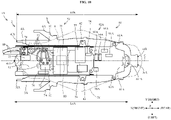
- Fig. 10 is a plan view of a rear portion of the straddled vehicle 1A.
- Fig. 10 shows the seat 20 in a two-dot chain line.
- Fig. 10 omits the side cover 23 and other elements.
- the body frame 2 has a right seat frame 4A and a left seat frame 5A.
- the right seat frame 4A extends in the longitudinal direction X in the plan view of the vehicle.
- the left seat frame 5A is located leftward of the right seat frame 4A.
- the left seat frame 5A extends in the longitudinal direction X in the plan view of the vehicle.
- the right seat frame 4A has a front end 4fA and a rear end 4rA.
- the left seat frame 5A has a front end 5fA and a rear end 5rA.
- the front ends 4fA and 5fA are connected to the main frame 3, respectively.
- the right seat frame 4A and left seat frame 5A are relatively short in the longitudinal direction X.
- Fig. 10 shows a length LfA.
- the length LfA is a length in the longitudinal direction X of the right seat frame 4A and left seat frame 5A. More particularly, the length LfA is a distance in the longitudinal direction X between the front ends 4fA and 5fA and the rear ends 4rA and 5rA.
- the length LfA is smaller than the length Lf of the right seat frame 4 and left seat frame 5 in the first embodiment.
- the body frame 2 has a right backstay 6A and a left backstay 7A.
- the right backstay 6A extends in the longitudinal direction X in the plan view of the vehicle.
- the left backstay 7A is located leftward of the right backstay 6A.
- the left backstay 7A extends in the longitudinal direction X in the plan view of the vehicle.
- the right backstay 6A is connected to the main frame 3 and right seat frame 4A.
- the left backstay 7A is connected to the main frame 3 and left seat frame 5A.
- the right backstay 6A and left backstay 7A support the bracket 8.
- the seat 20 is located above the right seat frame 4A and left seat frame 5A.
- the seat 20 overlaps the right seat frame 4A and left seat frame 5A in the plan view of the vehicle.
- the seat 20 is located above the right backstay 6A and left backstay 7A.
- the seat 20 overlaps the right backstay 6A and left backstay 7A in the plan view of the vehicle.
- the seat 20 is located above the bracket 8.
- the seat 20 overlaps the bracket 8 in the plan view of the vehicle.
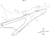
- Fig. 11 is a left side view of the rear portion of the straddled vehicle 1A.
- Fig. 11 shows the seat 20 in a two-dot chain line.
- Fig. 11 omits the side cover 23 and other elements.
- the right seat frame 4A and left seat frame 5 extend rearward and upward in the side view of the vehicle, respectively.
- the right backstay 6A is located below the right seat frame 4A in the side view of the vehicle.
- the left backstay 7A is located below the left seat frame 5A in the side view of the vehicle.
- the right backstay 6A and left backstay 7A extend rearward and upward in the side view of the vehicle, respectively.
- the bracket 8 is located below the right seat frame 4A and left seat frame 5A in the side view of the vehicle.
- the seat 20 is located above the right seat frame 4A and left seat frame 5A in the side view of the vehicle.
- the first case 41 is located leftward of the right seat frame 4A, rightward of the left seat frame 5A, and below the seat 20.
- the straddled vehicle 1A comprises a second case 61A.
- the second case 61A is located leftward of the right seat frame 4A, rightward of the left seat frame 5A, below the seat 20, and behind the first case 41.
- the first case 41 is located leftward of the right backstay 6A, and rightward of the left backstay 7A.
- the second case 61A is located leftward of the right backstay 6A and rightward of the left backstay 7A.
- the first case 41 is located above the bracket 8.
- the first case 41 overlaps the bracket 8 in the plan view of the vehicle.
- the second case 61A is located more rearward than the bracket 8.
- the second case 61A does not overlap the bracket 8 in the plan view of the vehicle.
- the first case 41 and second case 61A overlap the seat 20 in the plan view of the vehicle.
- the first case 41 of the straddled vehicle 1A has the same shape as the first case 41 of the straddled vehicle 1.
- the second case 61A of the straddled vehicle 1A has a shape different from the second case 61 of the straddled vehicle 1.
- the first case 41 has a front end 41f.
- the front end 41f of the first case 41 is located, with respect to the longitudinal direction X, in a position corresponding to the front ends 4fA and 5fA or more forward than the front ends 4fA and 5fA.
- Fig. 10 shows a length LcA.
- the length LcA is an entire length in the longitudinal direction X of the first case 41 and second case 61A. More particularly, the length LcA is a distance in the longitudinal direction X between the front end 41f of the first case 41 and a rear end 61rA of the second case 61A.
- the length LcA is smaller than the length LfA.
- the length LcA is smaller than the length Lc of the entirety of the first case 41 and second case 61 in the first embodiment.
- the first case 41 is supported by the right seat frame 4A and left seat frame 5A.
- the first right mounting seat 42 is located above the right seat frame 4A.
- the first right mounting seat 42 is connected to the right seat frame 4A.
- the first left mounting seat 43 is located above the left seat frame 5A.
- the first left mounting seat 43 is connected to the left seat frame 5A.
- the first case 41 is further supported by the bracket 8.
- the second case 61A is supported by the right seat frame 4A and left seat frame 5A.
- the second case 61A has a second right mounting seat 62A and a second left mounting seat 63A.
- the second right mounting seat 62A is located more rearward than the first right mounting seat 42.
- the second right mounting seat 62A is located above the right seat frame 4A.
- the second right mounting seat 62A is connected to the right seat frame 4A.
- the second left mounting seat 63A is located more rearward than the first left mounting seat 43.
- the second left mounting seat 63A is located above the left seat frame 5A.
- the second left mounting seat 63A is connected to the left seat frame 5A.
- the first case 41 extends rearward from the front end 5fA of the left seat frame 5A in the side view of the vehicle.
- the first case 41 overlaps the front end 5fA of the left seat frame 5A in the side view of the vehicle.
- the first case 41 extends rearward from the front end 4fA of the right seat frame 4A in the side view of the vehicle.
- the first case 41 overlaps the front end 4fA of the right seat frame 4A in the side view of the vehicle.
- the first electrical components 70 in the second embodiment are the same as the first electrical components 70 in the first embodiment. That is, the first electrical components 70 are common to the straddled vehicle 1 and straddled vehicle 1A.
- first electrical components 70 and the types of first electrical components 70 are the same in the straddled vehicle 1 and straddled vehicle 1A.
- first electrical components 70 in the second embodiment comprise the battery 71, hydraulic unit 72, steel pipes 73, joint member 74, main relay 75, fan relay 76, fuse box 77, stop lamp relay 78, starter relay 79, and inertial measurement unit 80.
- the number of first electrical components 70 in the second embodiment is ten, for example.
- each first electrical component 70 is the same in the straddled vehicle 1 and straddled vehicle 1A.
- the battery 71 mounted on the straddled vehicle 1A has the same shape as the battery 71 mounted on the straddled vehicle 1.
- first electrical components 70 is the same in the straddled vehicle 1 and straddled vehicle 1A.
- the battery 71 and hydraulic unit 72 are arranged to align in the longitudinal direction X in the plan view of the vehicle.
- the arrangement of each first electrical component 70 relative to the first case 41 is the same in the straddled vehicle 1 and straddled vehicle 1A.
- the battery 71 is located in the middle portion 52 of the first case 41.
- the second electrical components 90 in the second embodiment are different from the second electrical components 90 in the first embodiment.
- the number of second electrical components 90 and the types of second electrical components 90 are different between the straddled vehicle 1 and straddled vehicle 1A.
- the second electrical components 90 of the straddled vehicle 1A comprise a first connector 91A, a second connector 92A, a third connector 93A, and an on-board diagnostics 96A.
- the second connector 92A comprises a second right connector 93A and a second left connector 94A.
- the second electrical components 90 of the straddled vehicle 1A do not comprise the heater relay 97 or seat heater switch 98 mounted on the straddled vehicle 1.
- the number of second electrical components 90 of the straddled vehicle 1A is five.
- the number of second electrical components 90 of the straddled vehicle 1A is smaller than the number of second electrical components 90 of the straddled vehicle 1.
- the number of second electrical components 90 is smaller than the number of first electrical components 70.
- each second electrical component 90 is different between the straddled vehicle 1 and straddled vehicle 1A.
- the first connector 91A has a shape different from the first connector 91.
- the number of terminals on the first connector 91A is different from the number of terminals on the first connector 91.
- the second connector 92A has a shape different from the second connector 92.
- the third connector 95A has a shape different from the third connector 95.
- the on-board diagnostics 96A has a shape different from the on-board diagnostics 96.
- each second electrical component 90 is different between the straddled vehicle 1 and straddled vehicle 1A.
- the on-board diagnostics 96 is located more rearward than the first connector 91.
- the on-board diagnostics 96A is located more forward than the first the connector 91A.
- the arrangement of each second electrical component 90 relative to the second cases 61 and 61A is different between the straddled vehicle 1 and straddled vehicle 1A.
- the on-board diagnostics 96 is located in the rear portion of the second case 61.
- the on-board diagnostics 96A is located in the front portion of the second case 61A.
- Fig. 12 is a perspective view of the first case 41 and second case 61A.
- the volume of the first case 41 is larger than the volume of the second case 61A.
- the second case 61A has a second bottom 64A, a second right wall 65A, and a second left wall 66A.
- the volume of the second case 61A corresponds to the volume of a space demarcated by the second bottom 64A, second right wall 65A, and second left wall 66A.
- the second bottom 64A is continuous with the first bottom 44.
- the second right wall 65A is continuous with the first right wall 45.
- the second left wall 66A is continuous with the first left wall 46.
- the second case 61A is an element separate from the first case 41.
- the second case 61A is formed integral.
- the second case 61A is inseparable into a plurality of members.
- the second case 61A is made of synthetic resin, for example.
- the first case 41 and second case 61A are formed separately.
- the first case 41 and second case 61A are formed using forming dies, respectively.
- the forming die for forming the second case 61A is different from the forming die for forming the first case 41.
- Fig. 13A is a plan view of the second case 61A.
- the second case 61A has a substantially rectangular shape in the plan view of the vehicle.
- the positional relationship of the second bottom 64A, second right wall 65A, and second left wall 66A is similar to the positional relationship of the second bottom 64, second right wall 65, and second left wall 66.
- the second bottom 64A extends in the longitudinal direction X and transverse direction Y in the plan view of the vehicle.
- the second right wall 65A extends in the longitudinal direction X in the plan view of the vehicle.
- the second left wall 66A is located leftward of the second right wall 65A.
- the second left wall 66A extends in the longitudinal direction X in the plan view of the vehicle.
- the second case 61A is relatively short in the longitudinal direction X.
- Fig. 13A shows a length L2A.
- the length L2A is a length of the second case 61A in the longitudinal direction X. More particularly, the length L2A is a distance in the longitudinal direction X between a front end 61fA of the second case 61A and the rear end 61rA of the second case 61A.
- the length L2A is smaller than the length L2 of the second case 61.
- the length L2A is smaller than the length L1.
- Fig. 13A shows a width W2A.
- the width W2A is a length of the second case 61A in the transverse direction Y. More particularly, the width W2A is a distance in the transverse direction Y between the second right wall 65A and second left wall 66A.
- the width W2A is substantially equal to the width W1.
- the width W2A is smaller than the length L2A.
- Fig. 13B is a side view of the second case 61A.
- the second case 61A has an upper edge 67A and a lower edge 68A in the side view of the vehicle.
- the upper edge 67A extends rearward and upward in the side view of the vehicle.
- the lower edge 68A extends rearward and upward in the side view of the vehicle.
- Fig. 13B shows a height H2A.
- the height H2A is a length in the up-down direction Z of the second case 61A. More particularly, the height H2A is a distance in the up-down direction Z between an upper end 61tA of the second case 61A and a lower end 61bA of the second case 61A.
- the height H2A is smaller than the height H1.
- Fig. 14A is a plan view showing a connection between the first case 41 and second case 61A.
- the first case 41 and second case 61A are connected to be attachable to and detachable from each other.
- the first case 41 and second case 61A are joined together by clamps 69.
- the first bottom 44 has a rear end portion 44r.
- the second bottom 64A has a front end portion 64fA.
- the rear end portion 44r and front end portion 64fA overlap in the plan view of the vehicle.
- the front end portion 64fA contacts the rear end portion 44r.
- the first right wall 45 has a rear end portion 45r.
- the second right wall 65A has a front end portion 65fA.
- the rear end portion 45r and front end portion 65fA are arranged in the transverse direction Y.
- the front end portion 65fA contacts the rear end portion 45r.
- the first left wall 46 has a rear end portion 46r.
- the second left wall 66A has a front end portion 66fA.
- the rear end portion 46r and front end portion 66fA are arranged in the transverse direction Y.
- the front end portion 66fA contacts the rear end portion 46r.
- Fig. 14B is a side view showing the connection between the first case 41 and second case 61A.
- the rear end portion 46r and front end portion 66fA overlap in the side view of the vehicle.
- the rear end portion 45r and front end portion 65fA overlap in the side view of the vehicle.
- the straddled vehicle 1A in the second embodiment produces the same effects as the straddled vehicle 1 in the first embodiment.
- the manufacturing cost of the first case 41 and second case 61A can be held down.
- the arrangement of the first electrical components 70 and second electrical components 90 can be designed efficiently.
- first and second embodiments produce the following effects.
- the length LfA is different from the length Lf.
- the right seat frame 4A and left seat frame 5A are different in type from the right seat frame 4 and left seat frame 5. Consequently, the straddled vehicle 1A is a model different from the straddled vehicle 1.
- the shape of the first case 41 is the same in the plural types of the straddled vehicles 1 and 1A. That is, the first case 41 is shared between the plural types, i.e. the straddled vehicles 1 and 1A. The manufacturing cost of the first case 41 can therefore be reduced effectively.
- the first case 41 extends rearward from the front end 4fA of the right seat frame 4A and the front end 5fA of the left seat frame 5A.
- the first case 41 can therefore easily be installed leftward of the right seat frame 4 and rightward of the left seat frame 5. Consequently, the first case 41 having the same shape can easily be installed relative to plural types of right seat frames 4 and 4A and left seat frames 5 and 5f having different lengths Lf and LfA.
- a switching is made between the second cases 61 and 61A.
- the members appropriate for the first case 41 are switched between the second cases 61 and 61A.
- the second case 61A has a shape different from the second case 61.
- the length LcA when the second case 61A is located behind the first case 41 is different from the length Lc when the second case 61 is located behind the first case 41.
- the lengths Lc and LcA can be switched by switching the second cases 61 and 61A without changing the first case 41.
- the first case 41 and second cases 61 and 61A are conveniently applicable to the plural types of right seat frames 4 and 4A and left seat frames 5 and 5A having different lengths Lf and LfA.
- the first case 41 can easily be shared between the plural types of straddled vehicles 1 and 1A.
- the volume of the second case 61 is smaller than the volume of the first case 41.
- the volume of the second case 61A is also smaller than the volume of the first case 41. So, even when preparing plural types of second cases 61 and 61A having different shapes, it is possible to keep down the manufacturing cost of the second cases 61 and 61A not to become excessively high. Thus, the overall manufacturing cost of the first case 41 and second cases 61 and 61A can be kept down conveniently.
- the arrangement of the first electrical components 70 is common to the straddled vehicles 1 and 1A. Consequently, the arrangement of the first electrical components 70 in the straddled vehicle 1 can be applied as arrangement of the first electrical components 70 in the straddled vehicle 1A. It is therefore sufficient to design once the arrangement of the first electrical components 70 for the straddled vehicles 1 and 1A. For example, when the arrangement of the first electrical components 70 is designed for the straddled vehicle 1, it is not necessary to design the arrangement of the first electrical component 70 for the straddled vehicle 1A. Consequently, an efficient laborsaving can be realized in the operation to design the arrangement of the first electrical components 70.
- the arrangement of the second electrical components 90 between the straddled vehicles 1 and 1A.
- the arrangement of the first electrical components 70 in the straddled vehicle 1 can be applied as arrangement of the first electrical components 70 in the straddled vehicle 1A.
- the arrangements of the first electrical components 70 and second electrical components 90 have been designed for the straddled vehicle 1, it is sufficient to design the arrangement of only the second electrical components 70 for the straddled vehicle 1A.
- the arrangement of the second electrical components 90 can therefore be designed easily.
- each first electrical component 70 is common to the straddled vehicles 1 and 1A. Therefore, the cost of designing the arrangement of the first electrical components 70 can be reduced with increased effect.
- the shapes of the second electrical components 90 are different between the straddled vehicles 1 and 1A.
- the second electrical components 90 are stored in the second cases 61 and 61A. Therefore, the arrangement of the second electrical components 90 is designed for each of the plural types of the straddled vehicles 1 and 1A. Consequently, even when the shapes of the second electrical components 90 are different between the straddled vehicles 1 and 1A, the arrangement of the second electrical components 90 in the straddled vehicle 1 can be optimized, and the arrangement of the second electrical components 90 in the straddled vehicle 1A can be optimized.
- the shapes of the second electrical components 90 are different between the straddled vehicles 1 and 1A, there is an important technical significance in storing the second electrical components 90 in the second cases 61 and 61A. In other words, when the shapes of the second electrical components 90 are different between the straddled vehicles 1 and 1A, there is all the more technical significance in designing an arrangement of only the second electrical components 90 for each of the straddled vehicles 1 and 1A.
- the number of second electrical components 90 differs between the straddled vehicles 1 and 1A.
- the second electrical components 90 are stored in the second cases 61 and 61A. Therefore, even when the number of second electrical components 90 differs between the straddled vehicles 1 and 1A, the arrangement of the second electrical components 90 in the straddled vehicle 1 can be optimized, and the arrangement of the second electrical components 90 in the straddled vehicle 1A can be optimized.
- the number of second electrical components 90 differs between the straddled vehicles 1 and 1A, there is all the more technical significance in storing the second electrical components 90 in the second cases 61 and 61A.
- the types of the second electrical components 90 differ between the straddled vehicles 1 and 1A.
- the second electrical components 90 are stored in the second cases 61 and 61A. Therefore, even when the types of the second electrical components 90 differ between the straddled vehicles 1 and 1A, the arrangement of the second electrical components 90 in the straddled vehicle 1 can be optimized, and the arrangement of the second electrical components 90 in the straddled vehicle 1A can be optimized.
- the types of the second electrical component 90 differ between the straddled vehicles 1 and 1A, there is all the more technical significance in storing the second electrical components 90 in the second cases 61 and 61A.
- straddled vehicle or motor vehicle used herein, and as used in the art, is meant to include at least the following terms used in the art: straddled vehicle or motor vehicle, straddle-type vehicle or motor vehicle, saddlestraddling (type) vehicle or motor vehicle, and includes: motorcycles, and motorbikes as well as tricycles, quad bikes, All Terrain Vehicles (ATVs), scooters, mopeds and snowmobiles.
- ATVs All Terrain Vehicles
Landscapes
- Engineering & Computer Science (AREA)
- Mechanical Engineering (AREA)
- Automatic Cycles, And Cycles In General (AREA)
Abstract
Description
- The present invention relates generally to a straddled vehicle, and in particular, though not exclusively, to a straddled vehicle having cases for storing electrical components.
-
Japanese Unexamined Patent Publication No. 2009-78795 (YAMAHA MOTOR CO LTD - A battery is one of the electrical components. In recent years, the number of electrical components mounted on a straddled vehicle has been on the increase. This has required an increase in the cost of designing an arrangement of each electrical component. Further, the case for storing each electrical component has increased in size. This has increased the case manufacturing cost.
- This invention has been made having regard to the state of the art noted above, and its object is to provide a straddled vehicle that allows efficient designing of an arrangement of electrical components, and curbing of the manufacturing cost of cases for storing the electrical components.
- The Inventor herein notes the following points. Different types of straddled vehicles may have seat frames of different lengths in the vehicle's longitudinal direction. The case is disposed between a right seat frame and a left seat frame. The case, therefore, has shapes different between different types of straddled vehicles having seat frames of different lengths. Consequently, plural types of cases having different shapes are prepared, respectively, for the plural types of straddled vehicles having the seat frames of different lengths. For example, plural types of forming dies are manufactured for the plural types of cases, respectively. Further, the plural types of cases are manufactured using the respective forming dies.
- The arrangement of each electrical component stored in the case is different between the plural types of cases having different shapes. The arrangement of each electrical component is designed for each case having a different shape.
- Based on the above findings, the Inventor herein has studied how to curb the cost of manufacturing plural types of cases having different shapes. Further, based on the above findings, the Inventor has studied how to realize labor-saving in the operation to design an arrangement of electrical components for each type of case.
- It is an object of at least one embodiment of at least one aspect of the present invention to seek to obviate or at least mitigate one or more problems and/or disadvantages in the prior art.
- Various aspects of the present invention are defined in the independent claim(s) appended hereto. Some optional and/or preferred features are defined in the dependent claims appended hereto.
- According to one aspect of the present invention there is provided a straddled vehicle. The straddled vehicle may comprise one or more of:
- a right seat frame that may extend in a vehicle's longitudinal direction in a plan view of the vehicle;
- a left seat frame that may be disposed leftward of the right seat frame, and may extend in the vehicle's longitudinal direction in the plan view of the vehicle;
- a seat that may be disposed above the right seat frame and the left seat frame;
- a first case that may be disposed leftward of the right seat frame, rightward of the left seat frame, and below the seat;
- a second case separate from the first case, that may be disposed leftward of the right seat frame, rightward of the left seat frame, below the seat, and behind the first case;
- a plurality of first electrical components that may be stored in the first case; and
- a plurality of second electrical components that may be stored in the second case.
- The first electrical components may comprise one or more of:
- a battery; and
- a hydraulic unit.
- The second electrical components may comprise a first connector for connecting wiring of a taillight.
- The second case may be smaller in volume than the first case.
- The straddled vehicle may comprise a first case and a second case. The first case and second case may be arranged leftward of the right seat frame, rightward of the left seat frame, and below the seat, respectively. The second case may be located behind the first case. The second case may be an element separate from the first case. Consequently, the length in the vehicle's longitudinal direction of the entirety of the first case and second case may be changed easily by changing the shape of the second case without changing the shape of the first case. Here, "changing the shape of the second case" may be, for example, preparing plural types of second cases different in shape and switching between the plural types of second cases. Thus, the first case and second case may be easily applicable to plural types of straddled vehicles with the right seat frame and left seat frame having different lengths in the vehicle's longitudinal direction. The first case having the same shape may be easily applicable to plural types of straddled vehicles with the right seat frame and left seat frame having different lengths in the vehicle's longitudinal direction. That is, the first case may be easily shared between plural types of straddled vehicles with the right seat frame and left seat frame having different lengths in the vehicle's longitudinal direction.
- When the first case is shared between plural types of straddled vehicles, the manufacturing cost of the first case may be reduced effectively. The volume of the second case may be smaller than the volume of the first case. So, even when plural types of second cases different in shape are prepared, the manufacturing cost of the second cases may be kept down not to become excessively high. Thus, by changing the shape of the second case, without changing the shape of the first case, the overall manufacturing cost of the first case and second case may be conveniently kept down.
- The first case may store a plurality of first electrical components. The second case may store a plurality of second electrical components. Consequently, when changing the shape of the second case, without changing the shape of the first case, it may be sufficient to design only an arrangement of the second electrical components. This may enable an effective reduction of the cost of designing the arrangement of the first electrical components. Further, the volume of the second case may be smaller than the volume of the first case. Even when the shape of the second case is changed, the arrangement of the second electrical components may be designed easily. Thus, by changing the shape of the second case, without changing the shape of the first case, the overall arrangement of the first electrical components and second electrical components may be efficiently designed.
- The first electrical components may comprise a battery and a hydraulic unit. The battery and hydraulic unit may be stored in the first case. Here, the shape of the battery cannot change easily between plural types of straddled vehicles. The shape of the hydraulic unit cannot change easily between plural types of straddled vehicles. Consequently, the cost of designing an arrangement of the battery and hydraulic unit may be reduced with increased effect. The second electrical components may comprise a first connector. The first connector may be stored in the second case. The arrangement of the first connector may therefore be designed easily. Here, the shape of the first connector may be easily changeable between plural types of straddled vehicles. Thus, the arrangement of the first connector may be designed flexibly according to various shapes of the first connector. This may enable an efficient designing of the arrangement of the battery, and/or hydraulic unit, and/or first connector.
- According to this straddled vehicle, as described above, the manufacturing cost of the first case and second case may be held down. Further, the arrangement of the first electrical components and second electrical components may be designed efficiently.
- When the first case and second case are optionally applied to plural types of straddled vehicles with different lengths in the vehicle's longitudinal direction of the right seat frame and left seat frame, the manufacturing cost of the first case and second case may be further held down, and the arrangement of the first electrical components and second electrical components may be designed with increased efficiency.
- In the above straddled vehicle, the second case may have a length in a vehicle's up-down direction smaller than a length in the vehicle's up-down direction of the first case.
- Even when plural types of second cases different in shape are prepared, it may be possible to keep down the manufacturing cost of the second cases so as not to become excessively high. By changing the shape of the second case, without changing the shape of the first case, the overall manufacturing cost of the first case and second case may be kept down with increased effect.
- In the above straddled vehicle, it may be preferred that the second case has a length in the vehicle's longitudinal direction corresponding to or smaller than a length in the vehicle's longitudinal direction of the first case.
- Even when plural types of second cases different in shape are prepared, it may be possible to keep down the manufacturing cost of the second cases so as not to become excessively high. By changing the shape of the second case, without changing the shape of the first case, the overall manufacturing cost of the first case and second case may be kept down with increased effect.
- In the above straddled vehicle, it may be preferred that the battery and the hydraulic unit are arranged to align in the vehicle's longitudinal direction in the plan view of the vehicle.
- This may conveniently prevent the length in a vehicle's transverse direction of the first case from becoming excessively large. The first case may therefore easily be located leftward of the right seat frame and rightward of the left seat frame. Further, the length in the vehicle's up-down direction of the first case may conveniently be prevented from becoming excessively large. The first case may therefore easily be located below the seat.
- In the above straddled vehicle, the first case may comprise one or more of;
- a front portion;
- a middle portion which may be located behind the front portion; and
- a rear portion which may be located behind the middle portion;
- The first case may be divided into the front portion, middle portion, and rear portion. The battery may be stored in the middle portion. Here, the depth of the middle portion may be larger than the depth of the front portion and/or the depth of the rear portion. Therefore, even when the battery is relatively large, the middle portion may conveniently store the battery.
- The above straddled vehicle may comprise a bracket disposed below the first case and in contact with the first case.
- The bracket may overlap the battery in the plan view of the vehicle.
- The bracket may be located below the first case. The bracket may contact the first case. The bracket may receive the load of the first case. The bracket may be located below the battery. The bracket may overlap the battery in the plan view of the vehicle. Consequently, the bracket may conveniently receive the load of the battery.
- In the above straddled vehicle, the first electrical components may further comprise:
- steel pipes which may connect to the hydraulic unit; and/or
- a joint member which may connect to the steel pipes.
- The first electrical components may comprise steel pipes and/or a joint member. The steel pipes and/or joint member may be stored in the first case. Here, the shapes of the steel pipes cannot easily change between plural types of straddled vehicles. The shape of the joint member cannot easily change between plural types of straddled vehicles. Consequently, the cost of designing an arrangement of the steel pipes and joint member may be reduced with increased effect.
- In the above straddled vehicle, it is preferred that the second electrical components may further comprise:
- a second connector which may be for connecting wiring of a rear flasher light; and/or
- a third connector which may be for connecting wiring of a license light.
- The second electrical components may comprise a second connector and/or a third connector. The second connector and/or third connector may be stored in the second case. The arrangement of the second connector and/or third connector may therefore be designed easily. Here, the shape of the second connector may be easily changeable between plural types of straddled vehicles. The shape of the third connector may be easily changeable between plural types of straddled vehicles. Consequently, the arrangement of the second connector may be designed flexibly according to various shapes of the second connector. Similarly, the arrangement of the third connector may be designed flexibly according to various shapes of the third connector.
- In the above straddled vehicle, the first electrical components may be larger in number than the second electrical components.
- The number of first electrical components may be larger than the number of second electrical components. Therefore, when changing the shape of the second case without changing the shape of the first case, the cost of designing the arrangement of the first electrical components may be reduced with increased effect. The number of second electrical components may be smaller than the number of first electrical components. Therefore, even when the shape of the second case is changed, the arrangement of the second electrical components may be designed with increased ease. Consequently, by changing the shape of the second case without changing the shape of the first case, the arrangement of the entirety of the first electrical components and second electrical components may be designed with increased efficiency.
- In the above straddled vehicle, the first case, in a side view of the vehicle, may extend rearward from a front end of the right seat frame and a front end of the left seat frame.
- The first case having the same shape may easily be installed relative to plural types of right seat frames and left seat frames having different lengths. Thus, the first case may easily be shared between plural types of straddled vehicles with right seat frames and left seat frames having different lengths.
- In the above straddled vehicle, the first case may comprise:
- a first right mounting seat which may be connected to the right seat frame; and/or
- a first left mounting seat which may be connected to the left seat frame; and/or
- a second right mounting seat which may be disposed more rearward than the first right mounting seat, and may be connected to the right seat frame; and/or
- a second left mounting seat which may be disposed more rearward than the first left mounting seat, and may be connected to the left seat frame.
- The second right mounting seat may be located more rearward than the first right mounting seat. Consequently, the position of the right seat frame connected to the second case may be different from the position of the right seat frame connected to the first case. The second left mounting seat may be located more rearward than the first left mounting seat. Consequently, the position of the left seat frame connected to the second case may be different from the position of the left seat frame connected to the first case. Therefore, even when the shape of the second case is changed, the right seat frame and left seat frame may conveniently support the first case and second case.
- In the above straddled vehicle, the first right mounting seat and/or the second right mounting seat may be located above the right seat frame, respectively; and/or
the first left mounting seat and/or the second left mounting seat may be located above the left seat frame, respectively. - The right seat frame and left seat frame may support the first case and second case with increased convenience.
- In the above straddled vehicle, the first case and the second case may be separably connected to each other.
- The first electrical components and second electrical components may be installed in positions close to each other.
- In the above straddled vehicle,
- the first case may have a first bottom;
- the second case may have a second bottom; and/or
- the second bottom may be continuous with the first bottom.
- This may allow electric wiring to be conveniently installed through the first case and second case.
- In the above straddled vehicle:
- the first case may comprise:
- a first right wall which may extend in the vehicle's longitudinal direction in the plan view of the vehicle; and/or
- a first left wall which may be disposed leftward of the first right wall and may extend in the vehicle's longitudinal direction in the plan view of the vehicle; and/or
- the second case may comprise:
- a second right wall which may extend in the vehicle's longitudinal direction in the plan view of the vehicle; and/or
- a second left wall which may be disposed leftward of the second right wall and extending in the vehicle's longitudinal direction in the plan view of the vehicle;
- the first right wall may have a rear end portion;
- the first left wall may have a rear end portion;
- the second right wall may have a front end portion;
- the second left wall may have a front end portion;
- the rear end portion of the first right wall and the front end portion of the second right wall may overlap in the side view of the vehicle;
- the rear end portion of the first right wall and the front end portion of the second right wall may contact each other;
- the rear end portion of the first left wall and the front end portion of the second left wall may overlap in the side view of the vehicle; and/or
- the rear end portion of the first left wall and the front end portion of the second left wall may contact each other.
- This may conveniently prevent the first case from shifting in the vehicle's transverse direction relative to the second case.
- Embodiments of the present invention will now be described, by way of example only, with reference to the accompanying drawings, which are:
- Fig. 1
- a left side view of a straddled vehicle according to a first embodiment;
- Fig. 2
- a plan view of a rear portion of the straddled vehicle;
- Fig. 3
- a left side view of the rear portion of the straddled vehicle;
- Fig. 4
- a plan view of the rear portion of the straddled vehicle;
- Fig. 5
- a perspective view of a first case and a second case;
- Fig. 6A
- a plan view of the first case, and
Fig. 6B is a side view of the first case; - Fig. 7A
- a plan view of the second case;
- Fig. 7B
- a side view of the second case;
- Fig. 8A
- a plan view showing a connection between the first case and second case;
- Fig. 8B
- a side view showing the connection between the first case and second case;
- Fig. 9
- a left side view of a straddled vehicle according to a second embodiment;
- Fig. 10
- a plan view of a rear portion of the straddled vehicle;
- Fig. 11
- a left side view of the rear portion of the straddled vehicle;
- Fig. 12
- a perspective view of a first case and a second case;
- Fig. 13A
- a plan view of the second case;
- Fig. 13B
- a side view of the second case;
- Fig. 14A
- a plan view showing a connection between the first case and second case; and
- Fig. 14B
- is a side view showing the connection between the first case and second case.
- A straddled vehicle according to several embodiments of the present invention will be described below with reference to the accompanying drawings. A street type vehicle will be described as one example of the straddled vehicle.
-
Fig. 1 is a left side view of a straddled vehicle 1 according to a first embodiment. The straddled vehicle 1 is, for example, a street type vehicle. -
Fig. 1 shows a longitudinal direction X, a transverse direction Y, and an up-down direction Z of the straddled vehicle 1. The longitudinal direction X, transverse direction Y, and up-down direction Z are defined with reference to a driver mounted on the straddled vehicle 1. The longitudinal direction X, transverse direction Y, and up-down direction Z are perpendicular to one another. The longitudinal direction X and transverse direction Y are horizontal. The up-down direction Z is vertical. - The terms "forward", "rearward", "upward", "downward", "rightward", and "leftward", respectively, mean "forward", "rearward", "upward", "downward", "rightward", and "leftward" as seen from the driver mounted on the straddled vehicle 1. Unless otherwise stated in this specification, "forward" and "rearward" include not only directions parallel to the longitudinal direction X but also directions approximate to the longitudinal direction X. The directions approximate to the longitudinal direction X are, for example, directions at angles not exceeding 45 degrees to the longitudinal direction X. Similarly, unless otherwise stated, "rightward" and "leftward" include not only directions parallel to the transverse direction Y but also directions approximate to the transverse direction Y. Unless otherwise stated, "upward" and "downward" include not only directions parallel to the up-down direction Z but also directions approximate to the up-down direction Z. For reference, the drawings show front, rear, up, down, right, and left, as appropriate.
- This specification uses various expressions describing arrangements, which have the following meanings, respectively. The following description will be made taking the transverse direction Y for example, and the same may be applied to the longitudinal direction X and up-down direction Z.
- The expression "Member Ma is located more rightward/leftward than Member Mb," defines a position in the transverse direction Y of Member Ma relative to Member Mb, and does not define a position in the longitudinal direction X or the up-down direction Z of Member Ma relative to Member Mb. In the case of this expression, Member Ma may, or may not, overlap Member Mb in a side view of the vehicle.
- The expression "Member Ma is located rightward/leftward of Member Mb," without reference to a looking direction defines a position in the transverse direction Y of Member Ma relative to Member Mb, a position in the longitudinal direction X of Member Ma relative to Member Mb, and a position in the up-down direction Z of Member Ma relative to Member Mb. This expression means that Member Ma is located more rightward/leftward than Member Mb, and that at least part of Member Ma overlaps at least part of Member Mb in a side view of the vehicle.
- The expression "Member Ma is located rightward/leftward of Member Mb in a plan view of the vehicle," defines a position in the transverse direction Y of Member Ma relative to Member Mb, and a position in the longitudinal direction X of Member Ma relative to Member Mb, and does not define a position in the up-down direction Z of Member Ma relative to Member Mb. This expression means that Member Ma is located more rightward/leftward than Member Mb, and that the front end of Member Ma is located more forward than the rear end of Member Mb, and that the rear end of Member Ma is located more rearward than the front end of Member Mb.
- The expression "Member Ma is located rightward/leftward of Member Mb in a front view of the vehicle," defines a position in the transverse direction Y of Member Ma relative to Member Mb, and a position in the up-down direction Z of Member Ma relative to Member Mb, and does not define a position in the longitudinal direction X of Member Ma relative to Member Mb. This expression means that Member Ma is located more rightward/leftward than Member Mb, the upper end of Member Ma is located higher than the lower end of Member Mb, and the lower end of Member Ma is located lower than the upper end of Member Mb.
- The straddled vehicle 1 comprises a
body frame 2. Thebody frame 2 has amain frame 3. Themain frame 3 extends from front to rear of thebody frame 2. More particularly, themain frame 3 extends rearward and downward in a side view of the vehicle. - The straddled vehicle 1 comprises a
steering device 11. Thesteering device 11 is supported by the front of thebody frame 2. Thesteering device 11 is rotatable relative to thebody frame 2. - The
steering device 11 has ahandlebar 12, afront suspension 13, and afront axle 14. Thehandlebar 12 is disposed in an upper portion of thesteering device 11. Thefront suspension 13 extends forward and downward from thehandlebar 12. Thefront axle 14 is disposed in a lower portion of thesteering device 11. Thefront axle 14 is supported by thefront suspension 13. - The straddled vehicle 1 comprises a
front wheel 15. Thefront wheel 15 is supported by thesteering device 11. Thefront wheel 15 is supported by thefront axle 14. Thefront wheel 15 is rotatable about thefront axle 14. - The straddled vehicle 1 comprises an
engine 17. At least part of theengine 17 is located below themain frame 3 in the side view of the vehicle. Theengine 17 is supported by thebody frame 2. For example, theengine 17 is supported by themain frame 3. Theengine 17 is fixed to thebody frame 2. Theengine 17 is not swingable relative to thebody frame 2. - The straddled vehicle 1 comprises a
fuel tank 18. Thefuel tank 18 is located above theengine 17 in the side view of the vehicle. At least part of thefuel tank 18 is located above themain frame 3 in the side view of the vehicle. Thefuel tank 18 is supported by thebody frame 2. - The straddled vehicle 1 comprises a
seat 20. Theseat 20 is located behind thefuel tank 18. Thewhole seat 20 is located lower than an upper end of thefuel tank 18. Part of theseat 20 is located in the same height position as thefuel tank 18 in the side view of the vehicle. Theseat 20 is located more rearward and higher than theengine 17. Theseat 20 is supported by thebody frame 2. - The
seat 20 has afront seat 21 and arear seat 22. Therear seat 22 is located behind thefront seat 21. Therear seat 22 is an element separate from thefront seat 21. Thefront seat 21 andrear seat 22 are separable from each other. - The straddled vehicle 1 comprises a
side cover 23. The side cover 23 is located below theseat 20 in the side view of the vehicle. - The straddled vehicle 1 comprises a
mudguard 24. Themudguard 24 extends rearward and downward from theside cover 23 in the side view of the vehicle. - The straddled vehicle 1 comprises a
taillight 25, arear flasher light 26, and alicense light 29. Thetaillight 25 is located behind theside cover 23 in the side view of the vehicle. Therear flasher light 26 and license light 29 are attached to themudguard 24. Therear flasher light 26 emits light for notifying third parties of course changes and the like of the straddled vehicle 1. Therear flasher light 26 has a leftrear flasher light 28 and a right rear flasher light not shown. Thelicense light 29 emits light for illuminating the license plate not shown. - The straddled vehicle 1 comprises a
pivot shaft 30, aswing arm 31, arear axle 32, and arear wheel 33. Thepivot shaft 30 is located behind theengine 17 in the side view of the vehicle. Thepivot shaft 30 is located lower than thefuel tank 18 andseat 20. Thepivot shaft 30 is supported by thebody frame 2. Theswing arm 31 is supported by thepivot shaft 30. Theswing arm 31 extends rearward from thepivot shaft 30. Theswing arm 31 is swingable about thepivot shaft 30. Therear axle 32 is supported by a rear portion of theswing arm 31. Therear wheel 33 is supported by therear axle 32. Therear wheel 33 is rotatable about therear axle 32. Therear wheel 33 is located below theseat 20 in the side view of the vehicle. - The straddled vehicle 1 comprises a
chain 34. Thechain 34 connects to therear wheel 33. Thechain 34 transmits power outputted from theengine 17 to therear wheel 33. Therear wheel 33 is rotated about therear axle 32 by the power transmitted from thechain 34. - The driver sits straddling the
front seat 21, and puts on a knee grip. The knee grip is a holding of part of the straddled vehicle 1 between the legs of the driver. The part of the straddled vehicle 1 is at least part of themain frame 3 andfuel tank 18, for example. The driver of the straddled vehicle 1 grasps thehandlebar 12 and controls thesteering device 11. A passenger of the straddled vehicle 1 sits on therear seat 22. -
Fig. 2 is a plan view of a rear portion of the straddled vehicle 1.Fig. 2 shows a vehicle center plane C. The vehicle center plane C is an imaginary plane perpendicular to the transverse direction Y. The vehicle center plane C passes through the center of the straddled vehicle 1.Fig. 2 shows theseat 20 in two-dot chain lines.Fig. 2 omits theside cover 23 and other elements. - The
body frame 2 has aright seat frame 4 and aleft seat frame 5. Theright seat frame 4 extends in the longitudinal direction X in the plan view of the vehicle. Theleft seat frame 5 is located leftward of theright seat frame 4. Theleft seat frame 5 extends in the longitudinal direction X in the plan view of the vehicle. - The
right seat frame 4 is located rightward of the vehicle center plane C. Theleft seat frame 5 is located leftward of the vehicle center plane C. - The
right seat frame 4 has afront end 4f and arear end 4r. Theleft seat frame 5 has afront end 5f and arear end 5r. The front ends 4f and 5f are connected to themain frame 3, respectively. -
Fig. 2 shows a length Lf. The length Lf is a length in the longitudinal direction X of theright seat frame 4 andleft seat frame 5. More particularly, the length Lf is a distance in the longitudinal direction X between thefront ends rear ends - The
body frame 2 has aright backstay 6 and aleft backstay 7. Theright backstay 6 extends in the longitudinal direction X in the plan view of the vehicle. Theleft backstay 7 is located leftward of theright backstay 6. Theleft backstay 7 extends in the longitudinal direction X in the plan view of the vehicle. - The
right backstay 6 is located rightward of the vehicle center plane C. Theleft backstay 7 is located leftward of the vehicle center plane C. - The
right backstay 6 has a front end 6f and arear end 6r. Theleft backstay 7 has afront end 7f and arear end 7r. The front ends 6f and 7f are connected to themain frame 3, respectively. Therear end 6r is connected to theright seat frame 4. Therear end 7r is connected to theleft seat frame 5. - The
body frame 2 has abracket 8. Thebracket 8 is supported by theright backstay 6 and leftbackstay 7. Thebracket 8 extends in the transverse direction Y. Thebracket 8 is located more rearward than thefront ends bracket 8 is located more rearward than thefront ends 6f and 7f. Thebracket 8 is located more forward than therear ends bracket 8 is located more forward than therear ends - The
bracket 8 has aplate portion 9 and two mountingseats 10. Theplate portion 9 has a substantially flat plate shape. At least part of theplate portion 9 is, in the plan view of the vehicle, located leftward of theright seat frame 4 and rightward of theleft seat frame 5. Each mountingseat 10 is, in the plan view of the vehicle, also located leftward of theright seat frame 4 and rightward of theleft seat frame 5. Each mountingseat 10 is connected to theplate portion 9. - The
seat 20 is located above theright seat frame 4 andleft seat frame 5. Theseat 20 overlaps theright seat frame 4 andleft seat frame 5 in the plan view of the vehicle. - The
seat 20 is located above theright backstay 6 and leftbackstay 7. Theseat 20 overlaps theright backstay 6 and leftbackstay 7 in the plan view of the vehicle. - The
seat 20 is located above thebracket 8. Theseat 20 overlaps thebracket 8 in the plan view of the vehicle. -
Fig. 3 is a left side view of the rear portion of the straddled vehicle 1.Fig. 3 shows theseat 20 in two-dot chain lines.Fig. 3 omits theside cover 23 and other elements. - The
left seat frame 5 extends rearward and upward in the side view of the vehicle. Theright seat frame 4 overlaps theleft seat frame 5 in the side view of the vehicle. Though not shown, theright seat frame 4 also extends rearward and upward in the side view of the vehicle. - The
left backstay 7 is located below theleft seat frame 5 in the side view of the vehicle. Theleft backstay 7 extends rearward and upward in the side view of the vehicle. Theright backstay 6 overlaps theleft backstay 7 in the side view of the vehicle. Though not shown, theright backstay 6 is also located below theright seat frame 4 in the side view of the vehicle. Theright backstay 6 also extends rearward and upward in the side view of the vehicle. - The
bracket 8 is located below theright seat frame 4 andleft seat frame 5 in the side view of the vehicle. - The
seat 20 is located above theright seat frame 4 andleft seat frame 5 in the side view of the vehicle. - Though not shown, the
right seat frame 4 andleft seat frame 5 are located above therear wheel 33 in the side view of the vehicle. Theright backstay 6 and leftbackstay 7 are located above therear wheel 33 in the side view of the vehicle. Thebracket 8 is located above therear wheel 33 in the side view of the vehicle. - Reference is made to
Fig. 3 . The straddled vehicle 1 comprises afirst case 41. Thefirst case 41 extends rearward from thefront end 5f of theleft seat frame 5 in the side view of the vehicle. Thefirst case 41 overlaps thefront end 5f of theleft seat frame 5 in the side view of the vehicle. Though not shown, thefirst case 41 extends rearward from thefront end 4f of theright seat frame 4 in the side view of the vehicle. Thefirst case 41 overlaps thefront end 4f of theright seat frame 4 in the side view of the vehicle. - The
first case 41 overlaps theleft seat frame 5 and leftbackstay 7 in the side view of the vehicle. Most part of thefirst case 41 is located below theleft seat frame 5 and above theleft backstay 7 in the side view of the vehicle. - The straddled vehicle 1 comprises a
second case 61. Thesecond case 61 is located behind thefirst case 41. - The
second case 61 overlaps theleft seat frame 5 and leftbackstay 7 in the side view of the vehicle. Most part of thesecond case 61 is located below theleft seat frame 5 and above theleft backstay 7 in the side view of the vehicle. - The
first case 41 andsecond case 61 are located below theseat 20 in the side view of the vehicle. - Though not shown, the
first case 41 andsecond case 61 are located above therear wheel 33 in the side view of the vehicle. -
Fig. 4 is a plan view of the rear portion of the straddled vehicle 1.Fig. 4 shows thefirst case 41 andsecond case 61.Fig. 4 shows theseat 20 in two-dot chain lines.Fig. 4 omits theside cover 23 and other elements. - The
first case 41 is located leftward of theright seat frame 4, rightward of theleft seat frame 5, and below theseat 20. Thesecond case 61 is located leftward of theright seat frame 4, rightward of theleft seat frame 5, below theseat 20, and behind thefirst case 41. - The
first case 41 is located leftward of theright backstay 6 and rightward of theleft backstay 7. Thesecond case 61 is located leftward of theright backstay 6 and rightward of theleft backstay 7. - The
first case 41 is located above thebracket 8. Thefirst case 41 overlaps thebracket 8 in the plan view of the vehicle. Thesecond case 61 is located more rearward than thebracket 8. Thesecond case 61 does not overlap thebracket 8 in the plan view of the vehicle. - The
first case 41 andsecond case 61 overlap theseat 20 in the plan view of the vehicle. - The
first case 41 has afront end 41f. Thefront end 41f is, with respect to the longitudinal direction X, located in a position corresponding to thefront ends front ends -
Fig. 4 shows a length Lc. The length Lc is an entire length in the longitudinal direction X of thefirst case 41 andsecond case 61. More particularly, the length Lc is a distance in the longitudinal direction X between thefront end 41f of thefirst case 41 and arear end 61r of thesecond case 61. The length Lc is smaller than the length Lf. - The
first case 41 is supported by theright seat frame 4 andleft seat frame 5. Thefirst case 41 has a firstright mounting seat 42 and a firstleft mounting seat 43. The firstright mounting seat 42 is located above theright seat frame 4. The firstright mounting seat 42 is connected to theright seat frame 4. The firstleft mounting seat 43 is located above theleft seat frame 5. The firstleft mounting seat 43 is connected to theleft seat frame 5. - The
first case 41 is further supported by thebracket 8. Thebracket 8 is located below thefirst case 41. Thebracket 8 contacts thefirst case 41. Thebracket 8 directly contacts thefirst case 41. Thebracket 8 receives the load of thefirst case 41. Thebracket 8 is further connected to thefirst case 41. - Specifically, the
plate portion 9 is located below thefirst case 41. Theplate portion 9 contacts thefirst case 41. Theplate portion 9 receives the load of thefirst case 41. The mountingseat 10 is located below thefirst case 41. The mountingseat 10 is connected to thefirst case 41. - The
second case 61 is supported by theright seat frame 4 andleft seat frame 5. Thesecond case 61 has a secondright mounting seat 62 and a secondleft mounting seat 63. The secondright mounting seat 62 is located more rearward than the firstright mounting seat 42. The secondright mounting seat 62 is located above theright seat frame 4. The secondright mounting seat 62 is connected to theright seat frame 4. The secondleft mounting seat 63 is located more rearward than the firstleft mounting seat 43. The secondleft mounting seat 63 is located above theleft seat frame 5. The secondleft mounting seat 63 is connected to theleft seat frame 5. - Reference is made to
Fig. 2. Fig. 2 showspositions 4j and 4k of theright seat frame 4. Theright seat frame 4 is, in the position 4j, connected to the firstright mounting seat 42. Theright seat frame 4 is, in theposition 4k, connected to the secondright mounting seat 62. Theposition 4k is located more rearward than the position 4j. -
Fig. 2 showspositions left seat frame 5. Theleft seat frame 5 is, in theposition 5j, connected to the firstleft mounting seat 43. Theleft seat frame 5 is, in theposition 5k, connected to the secondleft mounting seat 63. Theposition 5k is located more rearward than theposition 5j. - Reference is made to
Fig. 3 . The straddled vehicle 1 comprisesfastening members fastening member 58 fastens theleft seat frame 5 and firstleft mounting seat 43. Thefastening member 68 fastens theleft seat frame 5 and secondleft mounting seat 63. Thefastening members - Reference is made to
Fig. 4 . The straddled vehicle 1 comprises a plurality of firstelectrical components 70. The firstelectrical components 70 are stored in thefirst case 41. All the firstelectrical components 70 are stored in thefirst case 41. All the firstelectrical components 70 overlap thefirst case 41 in the plan view of the vehicle. - The first
electrical components 70 comprise abattery 71. Thebattery 71 is stored in thefirst case 41. Thewhole battery 71 overlaps thefirst case 41 in the plan view. The firstelectrical components 70 other than thebattery 71 are similarly located relative to thefirst case 41. - The
battery 71 is located above thebracket 8. Thebattery 71 overlaps thebracket 8 in the plan view of the vehicle. At least part of thebattery 71 overlaps thebracket 8 in the plan view of the vehicle. - The
battery 71 is located above theplate portion 9. Thebattery 71 overlaps theplate portion 9 in the plan view of the vehicle. - The first
electrical components 70 comprise ahydraulic unit 72. In the plan view of the vehicle, thebattery 71 andhydraulic unit 72 are arranged along the longitudinal direction X. For example, thehydraulic unit 72 is located in front of thebattery 71 in the plan view of the vehicle. - The
hydraulic unit 72 adjusts the hydraulic pressure of brake fluid. Specifically, the straddled vehicle 1 comprises a front brake mechanism (not shown) for braking thefront wheel 15 and a rear brake mechanism (not shown) for braking therear wheel 33. Thehydraulic unit 72 is connected to at least one of the front brake mechanism and rear brake mechanism. For example, thehydraulic unit 72 adjusts the hydraulic pressure of the brake fluid of the front brake mechanism to suppress the lock tendency of thefront wheel 15. For example, thehydraulic unit 72 adjusts the hydraulic pressure of the brake fluid of the rear brake mechanism to suppress the lock tendency of therear wheel 33. - The first
electrical components 70 comprisesteel pipes 73. Thesteel pipes 73 are connected to thehydraulic unit 72. Thesteel pipes 73 do not have flexibility. - The first
electrical components 70 comprise ajoint member 74. Thejoint member 74 is connected to thesteel pipes 73. For example, thejoint member 74 is located in front of thehydraulic unit 72 in the plan view of the vehicle. - The straddled vehicle comprises
flexible tubes 89. Theflexible tubes 89 are connected to thejoint member 74. Theflexible tubes 89 have flexibility. Thejoint member 74 joins thesteel pipes 73 andflexible tubes 89. Theflexible tubes 89 are rubber tubes, for example. Theflexible tubes 89 are not the firstelectrical components 70. This is because at least parts of theflexible tubes 89 are located outside thefirst case 41. - The first
electrical components 70 comprise amain relay 75. Themain relay 75 is located leftward of thejoint member 74 in the plan view of the vehicle, for example. - The first
electrical components 70 comprise afan relay 76. Thefan relay 76 is located leftward of thehydraulic unit 72 in the plan view of the vehicle, for example. - The first
electrical components 70 comprise afuse box 77. Thefuse box 77 is located behind thebattery 71 in the plan view of the vehicle, for example. - The first
electrical components 70 comprise astop lamp relay 78. Thestop lamp relay 78 is located behind thefuse box 77 in the plan view of the vehicle, for example. - The first
electrical components 70 comprise astarter relay 79. Thestarter relay 79 is located leftward of thefuse box 77 in the plan view of the vehicle, for example. - The first
electrical components 70 comprise aninertial measurement unit 80. Theinertial measurement unit 80 overlaps thebattery 71 in the plan view of the vehicle. Theinertial measurement unit 80 is located below thebattery 71, for example. - As described above, the number of first
electrical components 70 is ten, for example. Thebattery 71 is large compared with the firstelectrical components 70 other than thebattery 71. - The straddled vehicle 1 comprises a plurality of second
electrical components 90. The secondelectrical components 90 are stored in thesecond case 61. All the secondelectrical components 90 are stored in thesecond case 61. All the secondelectrical components 90 overlap thesecond case 61 in the plan view of the vehicle. - The second
electrical components 90 comprise afirst connector 91. Thefirst connector 91 connects wiring of thetaillight 25. Thefirst connector 91 is stored in thesecond case 61. The wholefirst connector 91 overlaps thesecond case 61 in the plan view. The secondelectrical components 90 other than thefirst connector 91 are similarly located relative to thesecond case 61. - The second
electrical components 90 comprise asecond connector 92. Thesecond connector 92 connects wiring of therear flasher light 26. For example, thesecond connector 92 is located in front of thefirst connector 91 in the plan view of the vehicle. - The
second connector 92 comprises a secondright connector 93 and a secondleft connector 94. The secondright connector 93 connects wiring of the right rear flasher light. The secondleft connector 94 connects wiring of the leftrear flasher light 28. For example, the secondright connector 93 and secondleft connector 94 are arranged to align in the transverse direction Y in the plan view of the vehicle. - The second
electrical components 90 comprise athird connector 95. Thethird connector 95 connects wiring of thelicense light 29. For example, thethird connector 95 is located in front of thefirst connector 91 in the plan view of the vehicle. For example, thethird connector 95 is located behind thesecond connector 92 in the plan view of the vehicle. - The second
electrical components 90 comprise an on-board diagnostics 96. For example, the on-board diagnostics 96 is located more rearward and more leftward than thefirst connector 91. - The second
electrical components 90 comprise aheater relay 97. Theheater relay 97 is located leftward of thesecond connector 92 in the plan view of the vehicle. - The second
electrical components 90 comprise aseat heater switch 98. Theseat heater switch 98 is located leftward of theheater relay 97 in the plan view of the vehicle. - As described above, the number of second
electrical components 90 is seven, for example. The number of secondelectrical components 90 is smaller than the number of firstelectrical components 70. -
Fig. 5 is a perspective view of thefirst case 41 andsecond case 61. The volume of thefirst case 41 is larger than the volume of thesecond case 61. - The
first case 41 has a first bottom 44, a firstright wall 45, and a firstleft wall 46. Thesecond case 61 has a second bottom 64, a secondright wall 65, and a secondleft wall 66. The volume of thefirst case 41 corresponds to the volume of a space demarcated by the first bottom 44, firstright wall 45, and firstleft wall 46. The volume of thesecond case 61 corresponds to the volume of a space demarcated by the second bottom 64, secondright wall 65, and secondleft wall 66. - The second bottom 64 is continuous with the
first bottom 44. The secondright wall 65 is continuous with the firstright wall 45. The secondleft wall 66 is continuous with the firstleft wall 46. - The
second case 61 is an element separate from thefirst case 41. - The
first case 41 is formed integral. Thefirst case 41 is inseparable into a plurality of members. Thesecond case 61 is formed integral. Thesecond case 61 is inseparable into a plurality of members. - The
first case 41 is made of synthetic resin, for example. Thesecond case 61 is made of synthetic resin, for example. Thefirst case 41 andsecond case 61 are formed separately. Thefirst case 41 andsecond case 61 are formed using forming dies, respectively. The forming die for forming thesecond case 61 is different from the forming die for forming thefirst case 41. -
Fig. 6A is a plan view of thefirst case 41. Thefirst case 41 has a substantially rectangular shape in the plan view of the vehicle. - The first bottom 44 crosses the vehicle center plane C in the plan view of the vehicle. The first bottom 44 extends in the longitudinal direction X and transverse direction Y in the plan view of the vehicle. The first
right wall 45 is located rightward of the vehicle center plane C in the plan view of the vehicle. The firstright wall 45 is located on a right edge of the first bottom 44 in the plan view of the vehicle. The firstright wall 45 is connected to thefirst bottom 44. The firstright wall 45 extends upward from thefirst bottom 44. The firstright wall 45 extends in the longitudinal direction X in the plan view of the vehicle. The firstleft wall 46 is located leftward of the firstright wall 45. The firstleft wall 46 is located leftward of the vehicle center plane C in the plan view of the vehicle. The firstleft wall 46 is located on a left edge of thefirst bottom 44. The firstleft wall 46 is connected to thefirst bottom 44. The firstleft wall 46 extends upward from thefirst bottom 44. The firstleft wall 46 extends in the longitudinal direction X in the plan view of the vehicle. - The first
right mounting seat 42 is connected to the firstright wall 45. The firstright mounting seat 42 extends rightward from the firstright wall 45. The firstleft mounting seat 43 is connected to the firstleft wall 46. The firstleft mounting seat 43 extends leftward from the firstleft wall 46. - The first
right wall 45 is located leftward of theright seat frame 4 in the plan view of the vehicle. The firstleft wall 46 is located rightward of theleft seat frame 5 in the plan view of the vehicle. -
Fig. 6A shows a length L1 and a width W1. The length L1 is a length of thefirst case 41 in the longitudinal direction X. More particularly, the length L1 is a distance in the longitudinal direction X between thefront end 41f of thefirst case 41 and therear end 41r of thefirst case 41. The width W1 is a length of thefirst case 41 in the transverse direction Y. More particularly, the width W1 is a distance in the transverse direction Y between the firstright wall 45 and firstleft wall 46. The length L1 is smaller than the length Lc. The length L1 is larger than the width W1. The width W1 is slightly smaller than a separation distance in the transverse direction Y between theright seat frame 4 andleft seat frame 5. -
Fig. 6B is a side view of thefirst case 41. Thefirst case 41 has anupper edge 47 and alower edge 48 in the side view of the vehicle. Theupper edge 47 corresponds to an upper edge of the firstleft wall 46, for example. Theupper edge 47 extends rearward and upward in the side view of the vehicle. Thelower edge 48 corresponds to a lower edge of the firstleft wall 46, for example. Thelower edge 48 corresponds to the first bottom 44, for example. In the side view of the vehicle, thelower edge 48 is curved to bulge downward. Thelower edge 48 comprises, in the side view of the vehicle, portions extending rearward and downward, and portions extending rearward and upward. - The
first case 41 is divided into afront portion 51, amiddle portion 52, and arear portion 53. Thefront portion 51, themiddle portion 52, and therear portion 53 are integrally formed. Thefront portion 51, themiddle portion 52, and therear portion 53 are inseparable from one another.Fig. 6B exemplifies boundary lines K1 and K2. The boundary line K1 is an imaginary line schematically showing a boundary between thefront portion 51 andmiddle portion 52. The boundary line K2 is an imaginary line schematically showing a boundary between themiddle portion 52 andrear portion 53. Themiddle portion 52 is located behind thefront portion 51. Therear portion 53 is located behind themiddle portion 52. -
Fig. 6B shows a depth D1 of thefront portion 51, a depth D2 of themiddle portion 52, and a depth D3 of therear portion 53. The depth D1 is a length on an imaginary line J1 of thefront portion 51. The depth D2 is a length on an imaginary line J2 of themiddle portion 52. The depth D3 is a length on an imaginary line J3 of therear portion 53. Here, the imaginary lines J1, J2, and J3 are parallel to the up-down direction Z, respectively. The imaginary line J1 crosses thefront portion 51 in the side view of the vehicle. The imaginary line J2 crosses themiddle portion 52 in the side view of the vehicle. The imaginary line J3 crosses therear portion 53 in the side view of the vehicle. The depth D2 is larger than the depth D1. The depth D2 is larger than the depth D3. Thus, themiddle portion 52 is a portion having the largest depth in thefirst case 41. - The
middle portion 52 stores thebattery 71. - Though not shown, the
middle portion 52 is located above thebracket 8. Themiddle portion 52 overlaps thebracket 8 in the plan view of the vehicle. Themiddle portion 52 directly contacts thebracket 8. Themiddle portion 52 is directly supported by thebracket 8. -
Fig. 6B shows a height H1. The height H1 is a length in the up-down direction Z of thefirst case 41. More particularly, the height H1 is a distance in the up-down direction Z between anupper end 41t of thefirst case 41 and alower end 41b of thefirst case 41. -
Fig. 7A is a plan view of thesecond case 61. Thesecond case 61 has a substantially rectangular shape in the plan view of the vehicle. - The second bottom 64 crosses the vehicle center plane C in the plan view of the vehicle. The second bottom 64 extends in the longitudinal direction X and transverse direction Y in the plan view of the vehicle. The second
right wall 65 is located rightward of the vehicle center plane C in the plan view of the vehicle. The secondright wall 65 is located on a right edge of the second bottom 64 in the plan view of the vehicle. The secondright wall 65 is connected to thesecond bottom 64. The secondright wall 65 extends upward from thesecond bottom 64. The secondright wall 65 extends in the longitudinal direction X in the plan view of the vehicle. The secondleft wall 66 is located leftward of the secondright wall 65. The secondleft wall 66 is located leftward of the vehicle center plane C in the plan view of the vehicle. The secondleft wall 66 is located on a left edge of the second bottom 64 in the plan view of the vehicle. The secondleft wall 66 is connected to thesecond bottom 64. The secondleft wall 66 extends upward from thesecond bottom 64. The secondleft wall 66 extends in the longitudinal direction X in the plan view of the vehicle. - The second
right mounting seat 62 is connected to the secondright wall 65. The secondright mounting seat 62 extends rightward from the secondright wall 65. The secondleft mounting seat 63 is connected to the secondleft wall 66. The secondleft mounting seat 63 extends leftward from the secondleft wall 66. - The second
right wall 65 is located leftward of theright seat frame 4 in the plan view of the vehicle. The secondleft wall 66 is located rightward of theleft seat frame 5 in the plan view of the vehicle. -
Fig. 7A shows a length L2 and a width W2. The length L2 is a length of thesecond case 61 in the longitudinal direction X. More particularly, the length L2 is a distance in the longitudinal direction X between afront end 61f of thesecond case 61 and therear end 61r of thesecond case 61. The width W2 is a length of thesecond case 61 in the transverse direction Y. More particularly, the width W2 is a distance in the transverse direction Y between the secondright wall 65 and secondleft wall 66. The length L2 is smaller than the length L1. The length L2 is larger than the width W2. The width W2 is substantially equal to the width W1. The width W2 is slightly smaller than a separation distance in the transverse direction Y between theright seat frame 4 andleft seat frame 5. -
Fig. 7B is a side view of thesecond case 61. Thesecond case 61 has anupper edge 67 and alower edge 68 in the side view of the vehicle. Theupper edge 67 corresponds to an upper edge of the secondleft wall 66, for example. Theupper edge 67 extends rearward and upward in the side view of the vehicle. Thelower edge 68 corresponds to a lower edge of the secondleft wall 66, for example. Thelower edge 68 corresponds to the second bottom 64, for example. In the side view of the vehicle, thelower edge 68 extends rearward and upward. -
Fig. 7B shows a height H2. The height H2 is a length in the up-down direction Z of thesecond case 61. More particularly, the height H2 is a distance in the up-down direction Z between anupper end 61t of thesecond case 61 and a lower end 61b of thesecond case 61. The height H2 is smaller than the height H1. -
Fig. 8A is a plan view showing a connection between thefirst case 41 andsecond case 61. Thefirst case 41 andsecond case 61 are connected to be attachable to and detachable from each other. - The
first case 41 andsecond case 61 are joined together byclamps 69. Theclamps 69 are plastic rivets, plastic push pins, or push clips, for example. Theclamps 69 are the removable type. Theclamps 69 can be removed easily. Thefirst case 41 andsecond case 61 can therefore be connected easily and separated easily. - The first bottom 44 has a
rear end portion 44r. The second bottom 64 has afront end portion 64f. Therear end portion 44r andfront end portion 64f are stacked in the up-down direction Z. Therear end portion 44r andfront end portion 64f overlap in the plan view of the vehicle. For example, thefront end portion 64f is placed above therear end portion 44r. Thefront end portion 64f contacts therear end portion 44r. - Further, the
rear end portion 44r andfront end portion 64f are joined together by theclamps 69. - The first
right wall 45 has arear end portion 45r. The secondright wall 65 has afront end portion 65f. Therear end portion 45r andfront end portion 65f are arranged in the transverse direction Y. For example, thefront end portion 65f is located rightward of therear end portion 45r. Thefront end portion 65f contacts therear end portion 45r. - The first
left wall 46 has arear end portion 46r. The secondleft wall 66 has afront end portion 66f. Therear end portion 46r andfront end portion 66f are arranged in the transverse direction Y. For example, thefront end portion 66f is located leftward of therear end portion 46r. Thefront end portion 66f contacts therear end portion 46r. -
Fig. 8B is a side view showing the connection between thefirst case 41 andsecond case 61. Therear end portion 46r andfront end portion 66f overlap in the side view of the vehicle. Though not shown, therear end portion 45r andfront end portion 65f overlap in the side view of the vehicle. - The straddled vehicle 1 comprises the
right seat frame 4,left seat frame 5,seat 20,first case 41, andsecond case 61. Theright seat frame 4 extends in the longitudinal direction X in a plan view of the vehicle. Theleft seat frame 5 is located leftward of theright seat frame 4. Theleft seat frame 5 extends in the longitudinal direction X in the plan view of the vehicle. Theseat 20 is located above theright seat frame 4 andleft seat frame 5. Thefirst case 41 is located leftward of theright seat frame 4, rightward of theleft seat frame 5, and below theseat 20. Thesecond case 61 is located leftward of theright seat frame 4, rightward of theleft seat frame 5, below theseat 20, and behind thefirst case 41. Thesecond case 61 is an element separate from thefirst case 41. Consequently, it is possible to change the length Lc easily by changing the shape of thesecond case 61 without changing the shape of thefirst case 41. Here, "changing the shape of thesecond case 61" indicates, for example, preparing plural types ofsecond cases 61 different in shape, and switching between the plural types ofsecond cases 61. Thus, thefirst case 41 andsecond case 61 are easily applicable to plural types of straddled vehicles 1 having different lengths Lf. Thefirst case 41 having the same shape is easily applicable to plural types of straddled vehicles 1 having different lengths Lf. That is, thefirst case 41 can easily be shared between plural types of straddled vehicles 1 having different lengths Lf. - When the
first case 41 is shared between plural types of straddled vehicles 1, the manufacturing cost of thefirst case 41 can be reduced effectively. The volume of thesecond case 61 is smaller than the volume of thefirst case 41. So, even when plural types ofsecond cases 61 different in shape are prepared, the manufacturing cost of thesecond case 61 can be kept down not to become excessively high. Thus, by changing the shape of thesecond case 61 without changing the shape of thefirst case 41, the overall manufacturing cost of thefirst case 41 andsecond case 61 can conveniently be kept down. - The
first case 41 stores a plurality of firstelectrical components 70. Thesecond case 61 stores a plurality of secondelectrical components 90. When the shape of thefirst case 41 remains unchanged, the arrangement of the firstelectrical components 70 cannot change easily. When the shape of thesecond case 61 changes, the arrangement of the secondelectrical components 90 is easily changeable. Consequently, when changing the shape of thesecond case 61 without changing the shape of thefirst case 41, it is sufficient to design only the arrangement of the secondelectrical components 90. This enables an effective reduction of the cost of designing the arrangement of the firstelectrical components 70. Further, the volume of thesecond case 61 is smaller than the volume of thefirst case 41. Even when the shape of thesecond case 61 is changed, the arrangement of the secondelectrical components 90 can be designed easily. Thus, by changing the shape of thesecond case 61 without changing the shape of thefirst case 41, the overall arrangement of the firstelectrical components 70 and secondelectrical components 90 can be efficiently designed. - The first
electrical components 70 comprise thebattery 71 andhydraulic unit 72. Thebattery 71 andhydraulic unit 72 are stored in thefirst case 41. Here, the shape of thebattery 71 cannot change easily between plural types of straddled vehicles 1. The shape of thehydraulic unit 72 cannot change easily between plural types of straddled vehicles 1. Consequently, the cost of designing an arrangement of thebattery 71 andhydraulic unit 72 can be reduced with increased effect. The secondelectrical components 90 comprise thefirst connector 91. Thefirst connector 91 is stored in thesecond case 61. The arrangement of thefirst connector 91 can therefore be designed easily. Here, the shape of thefirst connector 91 is easily changeable between plural types of straddled vehicles 1. Thus, the arrangement of thefirst connector 91 can be designed flexibly according to various shapes of thefirst connector 91. This enables an efficient designing of the arrangement of thebattery 71,hydraulic unit 72, andfirst connector 91. - According to the straddled vehicle 1, as described above, the manufacturing cost of the
first case 41 andsecond case 61 can be held down. Further, the arrangement of the firstelectrical components 70 and secondelectrical components 90 can be designed efficiently. - The height H2 is smaller than the height H1. Thus, even when plural types of
second cases 61 different in shape are prepared, it is possible to keep down the manufacturing cost of thesecond cases 61 not to become excessively high. By changing the shape of thesecond case 61 without changing the shape of thefirst case 41, the overall manufacturing cost of thefirst case 41 andsecond case 61 can be kept down with increased effect. - The length L2 is smaller than the length L1. Thus, even when plural types of
second cases 61 different in shape are prepared, it is possible to keep down the manufacturing cost of thesecond cases 61 not to become excessively high. By changing the shape of thesecond case 61, without changing the shape of thefirst case 41, the overall manufacturing cost of thefirst case 41 andsecond case 61 can be kept down with increased effect. - The
battery 71 andhydraulic unit 72 are arranged to align in the longitudinal direction X in the plan view of the vehicle. This can conveniently prevent the width W1 from becoming excessively large. Thefirst case 41 can therefore easily be located leftward of theright seat frame 4 and rightward of theleft seat frame 5. Further, the height H1 can conveniently be prevented from becoming excessively large. Thefirst case 41 can therefore easily be located below theseat 20. - The
first case 41 is divided into thefront portion 51,middle portion 52, andrear portion 53. Themiddle portion 52 is located behind thefront portion 51. Therear portion 53 is located behind themiddle portion 52. The depth D2 of themiddle portion 52 is larger than the depth D1 of thefront portion 51 and the depth D3 of therear portion 53. Thebattery 71 is stored in themiddle portion 52. Therefore, even when thebattery 71 is relatively large, themiddle portion 52 can conveniently store thebattery 71. - The straddled vehicle 1 comprises the
bracket 8. Thebracket 8 is located below thefirst case 41. Thebracket 8 contacts thefirst case 41. Thebracket 8 receives the load of thefirst case 41. Thebracket 8 can therefore conveniently support thefirst case 41. - The
bracket 8 is located below thebattery 71. Thebracket 8 overlaps thebattery 71 in the plan view of the vehicle. Consequently, thebracket 8 can conveniently receive the load of thebattery 71. Even when thebattery 71 is relatively heavy, thebracket 8 can conveniently support thefirst case 41. - The
bracket 8 is located below themiddle portion 52. Thebracket 8 contacts themiddle portion 52. Consequently, thebracket 8 can conveniently receive the load of thebattery 71. Even when thebattery 71 is relatively heavy, thebracket 8 can conveniently support themiddle portion 52. - The first
electrical components 70 further comprise thesteel pipes 73 andjoint member 74. Thesteel pipes 73 andjoint member 74 are stored in thefirst case 41. Here, the shapes of thesteel pipes 73 cannot easily change between plural types of straddled vehicles 1. The shape of thejoint member 74 cannot easily change between plural types of straddled vehicles 1. Consequently, the cost of designing an arrangement of thesteel pipes 73 andjoint member 74 can be reduced with increased effect. - The second
electrical components 90 comprise thesecond connector 92 andthird connector 95. Thesecond connector 92 andthird connector 95 are stored in thesecond case 61. The arrangement of thesecond connector 92 andthird connector 95 can therefore be designed easily. Here, the shape of thesecond connector 92 is easily changeable between plural types of straddled vehicles 1. The shape of thethird connector 95 is easily changeable between plural types of straddled vehicles 1. Consequently, the arrangement of thesecond connector 92 can be designed flexibly according to various shapes of thesecond connector 92. The arrangement of thethird connector 95 can be designed flexibly according to various shapes of thethird connector 95. - The number of first
electrical components 70 is larger than the number of secondelectrical components 90. Therefore, when changing the shape of thesecond case 61 without changing the shape of thefirst case 41, the cost of designing the arrangement of the firstelectrical components 70 can be reduced with increased effect. The number of secondelectrical components 90 is smaller than the number of firstelectrical components 70. Therefore, even when the shape of thesecond case 90 is changed, the arrangement of the secondelectrical components 90 can be designed with increased ease. Consequently, by changing the shape of thesecond case 61 without changing the shape of thefirst case 41, the arrangement of the entirety of the firstelectrical components 70 and secondelectrical components 90 can be designed with increased efficiency. - In the side view of the vehicle, the
first case 41 extends rearward from thefront end 4f of theright seat frame 4 and thefront end 5f of theleft seat frame 5. Consequently, thefirst case 41 having the same shape can easily be installed relative to plural types of right seat frames 4 and left seat frames 5 having different lengths Lf. Thus, thefirst case 41 can easily be shared between plural types of straddled vehicles 1 having different lengths Lf. - The
first case 41 has the firstright mounting seat 42 and firstleft mounting seat 43. Thesecond case 61 has the secondright mounting seat 62 and secondleft mounting seat 63. The secondright mounting seat 62 is located more rearward than the firstright mounting seat 42. Consequently, theposition 4k of theright seat frame 4 connected to thesecond case 61 is different from the position 4j of theright seat frame 4 connected to thefirst case 41. The secondleft mounting seat 63 is located more rearward than the firstleft mounting seat 43. Consequently, theposition 5k of theleft seat frame 5 connected to thesecond case 61 is different from theposition 5j of theleft seat frame 5 connected to thefirst case 41. Therefore, even when the shape of thesecond case 61 is changed, theright seat frame 4 andleft seat frame 5 can conveniently support thefirst case 41 andsecond case 61. - The first
right mounting seat 42 and secondright mounting seat 62 are located above theright seat frame 4, respectively. Theright seat frame 4 can therefore support thefirst case 41 andsecond case 61 with increased convenience. The firstleft mounting seat 43 and secondleft mounting seat 63 are located above theleft seat frame 5, respectively. Theleft seat frame 5 can therefore support thefirst case 41 andsecond case 61 with increased convenience. - The
first case 41 andsecond case 61 are separably connected to each other. Consequently, the firstelectrical components 70 and secondelectrical components 90 can be installed in positions close to each other. In particular, the secondelectrical components 90 can be arranged close to thebattery 71. - The
first case 41 has thefirst bottom 44. Thesecond case 61 has thesecond bottom 64. The second bottom 64 is continuous with thefirst bottom 44. Therefore, electric wiring not shown can be installed conveniently through thefirst case 41 andsecond case 61. - The
first case 41 has the firstright wall 45 and firstleft wall 46. Thesecond case 61 has the secondright wall 65 and secondleft wall 66. The secondright wall 65 is continuous with the firstright wall 45. The secondleft wall 66 is continuous with the firstleft wall 46. Therefore, electric wiring can be installed through thefirst case 41 andsecond case 61 with increased convenience. - The first
right wall 45 has therear end portion 45r. The secondright wall 65 has thefront end portion 65f. Therear end portion 45r andfront end portion 65f overlap in the side view of the vehicle. Therear end portion 45r andfront end portion 65f contact each other. The firstleft wall 46 has therear end portion 46r. The secondleft wall 66 has thefront end portion 66f. Therear end portion 46r andfront end portion 66f overlap in the side view of the vehicle. Therear end portion 46r andfront end portion 66f contact each other. Thefirst case 41 andsecond case 61 can therefore conveniently be prevented from shifting in the transverse direction Y relative to each other. For example, thefirst case 41 can conveniently prevent thesecond case 61 from moving in the transverse direction Y relative to thefirst case 41. For example, thesecond case 61 can conveniently prevent thefirst case 41 from moving in the transverse direction Y relative to thesecond case 61. Thus, the relative position between thefirst case 41 andsecond case 61 can easily be kept constant. - The first bottom 44 has the
rear end portion 44r. The second bottom 64 has thefront end portion 64f. Therear end portion 44r andfront end portion 64f overlap in the plan view of the vehicle. Therear end portion 44r andfront end portion 64f contact each other. Thefirst case 41 andsecond case 61 can therefore conveniently be prevented from shifting in the up-down direction Z relative to each other. For example, thefirst case 41 can conveniently prevent thesecond case 61 from moving in the up-down direction Z relative to thefirst case 41. For example, thesecond case 61 can conveniently prevent thefirst case 41 from moving in the up-down direction Z relative to thesecond case 61. Thus, the relative position between thefirst case 41 andsecond case 61 can be kept constant with increased ease. -
Fig. 9 is a left side view of a straddledvehicle 1A according to a second embodiment. The straddledvehicle 1A according to the second embodiment is, for example, a street type vehicle. The straddledvehicle 1A according to the second embodiment is a model different from the straddled vehicle 1 according to the first embodiment. Components identical to those of the first embodiment are shown with the same signs, and will not particularly be described. - The
seat 20 has afront seat 21A and arear seat 22A. Thefront seat 21A andrear seat 22A are integrated. Thefront seat 21A andrear seat 22A are inseparable from each other. -
Fig. 10 is a plan view of a rear portion of the straddledvehicle 1A.Fig. 10 shows theseat 20 in a two-dot chain line.Fig. 10 omits theside cover 23 and other elements. - The
body frame 2 has aright seat frame 4A and aleft seat frame 5A. Theright seat frame 4A extends in the longitudinal direction X in the plan view of the vehicle. Theleft seat frame 5A is located leftward of theright seat frame 4A. Theleft seat frame 5A extends in the longitudinal direction X in the plan view of the vehicle. - The
right seat frame 4A has a front end 4fA and a rear end 4rA. Theleft seat frame 5A has a front end 5fA and a rear end 5rA. The front ends 4fA and 5fA are connected to themain frame 3, respectively. - The
right seat frame 4A andleft seat frame 5A are relatively short in the longitudinal direction X.Fig. 10 shows a length LfA. The length LfA is a length in the longitudinal direction X of theright seat frame 4A andleft seat frame 5A. More particularly, the length LfA is a distance in the longitudinal direction X between the front ends 4fA and 5fA and the rear ends 4rA and 5rA. The length LfA is smaller than the length Lf of theright seat frame 4 andleft seat frame 5 in the first embodiment. - The
body frame 2 has aright backstay 6A and aleft backstay 7A. Theright backstay 6A extends in the longitudinal direction X in the plan view of the vehicle. Theleft backstay 7A is located leftward of theright backstay 6A. Theleft backstay 7A extends in the longitudinal direction X in the plan view of the vehicle. - The
right backstay 6A is connected to themain frame 3 andright seat frame 4A. Theleft backstay 7A is connected to themain frame 3 andleft seat frame 5A. Theright backstay 6A and leftbackstay 7A support thebracket 8. - The
seat 20 is located above theright seat frame 4A andleft seat frame 5A. Theseat 20 overlaps theright seat frame 4A andleft seat frame 5A in the plan view of the vehicle. - The
seat 20 is located above theright backstay 6A and leftbackstay 7A. Theseat 20 overlaps theright backstay 6A and leftbackstay 7A in the plan view of the vehicle. - The
seat 20 is located above thebracket 8. Theseat 20 overlaps thebracket 8 in the plan view of the vehicle. -
Fig. 11 is a left side view of the rear portion of the straddledvehicle 1A.Fig. 11 shows theseat 20 in a two-dot chain line.Fig. 11 omits theside cover 23 and other elements. - The
right seat frame 4A andleft seat frame 5 extend rearward and upward in the side view of the vehicle, respectively. - The
right backstay 6A is located below theright seat frame 4A in the side view of the vehicle. Theleft backstay 7A is located below theleft seat frame 5A in the side view of the vehicle. Theright backstay 6A and leftbackstay 7A extend rearward and upward in the side view of the vehicle, respectively. - The
bracket 8 is located below theright seat frame 4A andleft seat frame 5A in the side view of the vehicle. - The
seat 20 is located above theright seat frame 4A andleft seat frame 5A in the side view of the vehicle. - Reference is made to
Fig. 10 . Thefirst case 41 is located leftward of theright seat frame 4A, rightward of theleft seat frame 5A, and below theseat 20. The straddledvehicle 1A comprises asecond case 61A. Thesecond case 61A is located leftward of theright seat frame 4A, rightward of theleft seat frame 5A, below theseat 20, and behind thefirst case 41. - The
first case 41 is located leftward of theright backstay 6A, and rightward of theleft backstay 7A. Thesecond case 61A is located leftward of theright backstay 6A and rightward of theleft backstay 7A. - The
first case 41 is located above thebracket 8. Thefirst case 41 overlaps thebracket 8 in the plan view of the vehicle. Thesecond case 61A is located more rearward than thebracket 8. Thesecond case 61A does not overlap thebracket 8 in the plan view of the vehicle. - The
first case 41 andsecond case 61A overlap theseat 20 in the plan view of the vehicle. - The
first case 41 of the straddledvehicle 1A has the same shape as thefirst case 41 of the straddled vehicle 1. Thesecond case 61A of the straddledvehicle 1A has a shape different from thesecond case 61 of the straddled vehicle 1. - The
first case 41 has afront end 41f. Thefront end 41f of thefirst case 41 is located, with respect to the longitudinal direction X, in a position corresponding to the front ends 4fA and 5fA or more forward than the front ends 4fA and 5fA. -
Fig. 10 shows a length LcA. The length LcA is an entire length in the longitudinal direction X of thefirst case 41 andsecond case 61A. More particularly, the length LcA is a distance in the longitudinal direction X between thefront end 41f of thefirst case 41 and a rear end 61rA of thesecond case 61A. The length LcA is smaller than the length LfA. The length LcA is smaller than the length Lc of the entirety of thefirst case 41 andsecond case 61 in the first embodiment. - The
first case 41 is supported by theright seat frame 4A andleft seat frame 5A. The firstright mounting seat 42 is located above theright seat frame 4A. The firstright mounting seat 42 is connected to theright seat frame 4A. The firstleft mounting seat 43 is located above theleft seat frame 5A. The firstleft mounting seat 43 is connected to theleft seat frame 5A. - The
first case 41 is further supported by thebracket 8. - The
second case 61A is supported by theright seat frame 4A andleft seat frame 5A. Thesecond case 61A has a secondright mounting seat 62A and a secondleft mounting seat 63A. The secondright mounting seat 62A is located more rearward than the firstright mounting seat 42. The secondright mounting seat 62A is located above theright seat frame 4A. The secondright mounting seat 62A is connected to theright seat frame 4A. The secondleft mounting seat 63A is located more rearward than the firstleft mounting seat 43. The secondleft mounting seat 63A is located above theleft seat frame 5A. The secondleft mounting seat 63A is connected to theleft seat frame 5A. - Reference is made to
Fig. 11 . Thefirst case 41 extends rearward from the front end 5fA of theleft seat frame 5A in the side view of the vehicle. Thefirst case 41 overlaps the front end 5fA of theleft seat frame 5A in the side view of the vehicle. Though not shown, thefirst case 41 extends rearward from the front end 4fA of theright seat frame 4A in the side view of the vehicle. Thefirst case 41 overlaps the front end 4fA of theright seat frame 4A in the side view of the vehicle. - Reference is made to
Fig. 10 . The firstelectrical components 70 in the second embodiment are the same as the firstelectrical components 70 in the first embodiment. That is, the firstelectrical components 70 are common to the straddled vehicle 1 and straddledvehicle 1A. - The number of first
electrical components 70 and the types of firstelectrical components 70 are the same in the straddled vehicle 1 and straddledvehicle 1A. Specifically, the firstelectrical components 70 in the second embodiment comprise thebattery 71,hydraulic unit 72,steel pipes 73,joint member 74,main relay 75,fan relay 76,fuse box 77,stop lamp relay 78,starter relay 79, andinertial measurement unit 80. The number of firstelectrical components 70 in the second embodiment is ten, for example. - The shape of each first
electrical component 70 is the same in the straddled vehicle 1 and straddledvehicle 1A. For example, thebattery 71 mounted on the straddledvehicle 1A has the same shape as thebattery 71 mounted on the straddled vehicle 1. - The arrangement of first
electrical components 70 is the same in the straddled vehicle 1 and straddledvehicle 1A. For example, in the straddledvehicle 1A also, thebattery 71 andhydraulic unit 72 are arranged to align in the longitudinal direction X in the plan view of the vehicle. Further, the arrangement of each firstelectrical component 70 relative to thefirst case 41 is the same in the straddled vehicle 1 and straddledvehicle 1A. Though not shown, in the straddledvehicle 1A also, thebattery 71 is located in themiddle portion 52 of thefirst case 41. - The second
electrical components 90 in the second embodiment are different from the secondelectrical components 90 in the first embodiment. - The number of second
electrical components 90 and the types of secondelectrical components 90 are different between the straddled vehicle 1 and straddledvehicle 1A. Specifically, the secondelectrical components 90 of the straddledvehicle 1A comprise afirst connector 91A, asecond connector 92A, athird connector 93A, and an on-board diagnostics 96A. Thesecond connector 92A comprises a secondright connector 93A and a secondleft connector 94A. However, the secondelectrical components 90 of the straddledvehicle 1A do not comprise theheater relay 97 orseat heater switch 98 mounted on the straddled vehicle 1. The number of secondelectrical components 90 of the straddledvehicle 1A is five. The number of secondelectrical components 90 of the straddledvehicle 1A is smaller than the number of secondelectrical components 90 of the straddled vehicle 1. - In the straddled
vehicle 1A also, the number of secondelectrical components 90 is smaller than the number of firstelectrical components 70. - The shape of each second
electrical component 90 is different between the straddled vehicle 1 and straddledvehicle 1A. For example, thefirst connector 91A has a shape different from thefirst connector 91. For example, the number of terminals on thefirst connector 91A is different from the number of terminals on thefirst connector 91. Similarly, thesecond connector 92A has a shape different from thesecond connector 92. Thethird connector 95A has a shape different from thethird connector 95. The on-board diagnostics 96A has a shape different from the on-board diagnostics 96. - The arrangement of each second
electrical component 90 is different between the straddled vehicle 1 and straddledvehicle 1A. For example, in the straddled vehicle 1, the on-board diagnostics 96 is located more rearward than thefirst connector 91. In the straddledvehicle 1A, on the other hand, the on-board diagnostics 96A is located more forward than the first theconnector 91A. Further, the arrangement of each secondelectrical component 90 relative to thesecond cases vehicle 1A. For example, in the straddled vehicle 1, the on-board diagnostics 96 is located in the rear portion of thesecond case 61. In the straddledvehicle 1A, on the other hand, the on-board diagnostics 96A is located in the front portion of thesecond case 61A. -
Fig. 12 is a perspective view of thefirst case 41 andsecond case 61A. The volume of thefirst case 41 is larger than the volume of thesecond case 61A. - The
second case 61A has asecond bottom 64A, a secondright wall 65A, and a secondleft wall 66A. The volume of thesecond case 61A corresponds to the volume of a space demarcated by thesecond bottom 64A, secondright wall 65A, and secondleft wall 66A. - The
second bottom 64A is continuous with thefirst bottom 44. The secondright wall 65A is continuous with the firstright wall 45. The secondleft wall 66A is continuous with the firstleft wall 46. - The
second case 61A is an element separate from thefirst case 41. - The
second case 61A is formed integral. Thesecond case 61A is inseparable into a plurality of members. - The
second case 61A is made of synthetic resin, for example. Thefirst case 41 andsecond case 61A are formed separately. Thefirst case 41 andsecond case 61A are formed using forming dies, respectively. The forming die for forming thesecond case 61A is different from the forming die for forming thefirst case 41. -
Fig. 13A is a plan view of thesecond case 61A. Thesecond case 61A has a substantially rectangular shape in the plan view of the vehicle. - The positional relationship of the
second bottom 64A, secondright wall 65A, and secondleft wall 66A is similar to the positional relationship of the second bottom 64, secondright wall 65, and secondleft wall 66. Thesecond bottom 64A extends in the longitudinal direction X and transverse direction Y in the plan view of the vehicle. The secondright wall 65A extends in the longitudinal direction X in the plan view of the vehicle. The secondleft wall 66A is located leftward of the secondright wall 65A. The secondleft wall 66A extends in the longitudinal direction X in the plan view of the vehicle. - The
second case 61A is relatively short in the longitudinal direction X.Fig. 13A shows a length L2A. The length L2A is a length of thesecond case 61A in the longitudinal direction X. More particularly, the length L2A is a distance in the longitudinal direction X between a front end 61fA of thesecond case 61A and the rear end 61rA of thesecond case 61A. The length L2A is smaller than the length L2 of thesecond case 61. The length L2A is smaller than the length L1. -
Fig. 13A shows a width W2A. The width W2A is a length of thesecond case 61A in the transverse direction Y. More particularly, the width W2A is a distance in the transverse direction Y between the secondright wall 65A and secondleft wall 66A. The width W2A is substantially equal to the width W1. The width W2A is smaller than the length L2A. -
Fig. 13B is a side view of thesecond case 61A. Thesecond case 61A has anupper edge 67A and alower edge 68A in the side view of the vehicle. Theupper edge 67A extends rearward and upward in the side view of the vehicle. Thelower edge 68A extends rearward and upward in the side view of the vehicle. -
Fig. 13B shows a height H2A. The height H2A is a length in the up-down direction Z of thesecond case 61A. More particularly, the height H2A is a distance in the up-down direction Z between an upper end 61tA of thesecond case 61A and a lower end 61bA of thesecond case 61A. The height H2A is smaller than the height H1. -
Fig. 14A is a plan view showing a connection between thefirst case 41 andsecond case 61A. Thefirst case 41 andsecond case 61A are connected to be attachable to and detachable from each other. - The
first case 41 andsecond case 61A are joined together byclamps 69. - The first bottom 44 has a
rear end portion 44r. Thesecond bottom 64A has a front end portion 64fA. Therear end portion 44r and front end portion 64fA overlap in the plan view of the vehicle. The front end portion 64fA contacts therear end portion 44r. - Further, the
rear end portion 44r and front end portion 64fA are fixed by theclamps 69. - The first
right wall 45 has arear end portion 45r. The secondright wall 65A has a front end portion 65fA. Therear end portion 45r and front end portion 65fA are arranged in the transverse direction Y. The front end portion 65fA contacts therear end portion 45r. - The first
left wall 46 has arear end portion 46r. The secondleft wall 66A has a front end portion 66fA. Therear end portion 46r and front end portion 66fA are arranged in the transverse direction Y. The front end portion 66fA contacts therear end portion 46r. -
Fig. 14B is a side view showing the connection between thefirst case 41 andsecond case 61A. Therear end portion 46r and front end portion 66fA overlap in the side view of the vehicle. Though not shown, therear end portion 45r and front end portion 65fA overlap in the side view of the vehicle. - The straddled
vehicle 1A in the second embodiment produces the same effects as the straddled vehicle 1 in the first embodiment. For example, the manufacturing cost of thefirst case 41 andsecond case 61A can be held down. Further, the arrangement of the firstelectrical components 70 and secondelectrical components 90 can be designed efficiently. - Further, the first and second embodiments produce the following effects.
- The length LfA is different from the length Lf. Thus, the
right seat frame 4A andleft seat frame 5A are different in type from theright seat frame 4 andleft seat frame 5. Consequently, the straddledvehicle 1A is a model different from the straddled vehicle 1. The shape of thefirst case 41 is the same in the plural types of the straddledvehicles 1 and 1A. That is, thefirst case 41 is shared between the plural types, i.e. the straddledvehicles 1 and 1A. The manufacturing cost of thefirst case 41 can therefore be reduced effectively. - In the side view of the vehicle, the
first case 41 extends rearward from the front end 4fA of theright seat frame 4A and the front end 5fA of theleft seat frame 5A. Thefirst case 41 can therefore easily be installed leftward of theright seat frame 4 and rightward of theleft seat frame 5. Consequently, thefirst case 41 having the same shape can easily be installed relative to plural types of right seat frames 4 and 4A and left seat frames 5 and 5f having different lengths Lf and LfA. - According to the straddled
vehicles 1 and 1A, a switching is made between thesecond cases vehicles 1 and 1A, the members appropriate for thefirst case 41 are switched between thesecond cases second case 61A has a shape different from thesecond case 61. The length LcA when thesecond case 61A is located behind thefirst case 41 is different from the length Lc when thesecond case 61 is located behind thefirst case 41. Thus, the lengths Lc and LcA can be switched by switching thesecond cases first case 41. Consequently, thefirst case 41 andsecond cases first case 41 can easily be shared between the plural types of straddledvehicles 1 and 1A. - The volume of the
second case 61 is smaller than the volume of thefirst case 41. The volume of thesecond case 61A is also smaller than the volume of thefirst case 41. So, even when preparing plural types ofsecond cases second cases first case 41 andsecond cases - The arrangement of the first
electrical components 70 is common to the straddledvehicles 1 and 1A. Consequently, the arrangement of the firstelectrical components 70 in the straddled vehicle 1 can be applied as arrangement of the firstelectrical components 70 in the straddledvehicle 1A. It is therefore sufficient to design once the arrangement of the firstelectrical components 70 for the straddledvehicles 1 and 1A. For example, when the arrangement of the firstelectrical components 70 is designed for the straddled vehicle 1, it is not necessary to design the arrangement of the firstelectrical component 70 for the straddledvehicle 1A. Consequently, an efficient laborsaving can be realized in the operation to design the arrangement of the firstelectrical components 70. - There is a difference in the arrangement of the second
electrical components 90 between the straddledvehicles 1 and 1A. As noted above, the arrangement of the firstelectrical components 70 in the straddled vehicle 1 can be applied as arrangement of the firstelectrical components 70 in the straddledvehicle 1A. Thus, for the straddledvehicles 1 and 1A, it is sufficient to design twice the arrangement of only the secondelectrical components 90. For example, when the arrangements of the firstelectrical components 70 and secondelectrical components 90 have been designed for the straddled vehicle 1, it is sufficient to design the arrangement of only the secondelectrical components 70 for the straddledvehicle 1A. The arrangement of the secondelectrical components 90 can therefore be designed easily. - Consequently, it is possible to reduce effectively the cost of designing arrangements of the first
electrical components 70 and secondelectrical components 90 for the plural types of straddledvehicles 1 and 1A. - The shape of each first
electrical component 70 is common to the straddledvehicles 1 and 1A. Therefore, the cost of designing the arrangement of the firstelectrical components 70 can be reduced with increased effect. - The shapes of the second
electrical components 90 are different between the straddledvehicles 1 and 1A. Here, the secondelectrical components 90 are stored in thesecond cases electrical components 90 is designed for each of the plural types of the straddledvehicles 1 and 1A. Consequently, even when the shapes of the secondelectrical components 90 are different between the straddledvehicles 1 and 1A, the arrangement of the secondelectrical components 90 in the straddled vehicle 1 can be optimized, and the arrangement of the secondelectrical components 90 in the straddledvehicle 1A can be optimized. Thus, when the shapes of the secondelectrical components 90 are different between the straddledvehicles 1 and 1A, there is an important technical significance in storing the secondelectrical components 90 in thesecond cases electrical components 90 are different between the straddledvehicles 1 and 1A, there is all the more technical significance in designing an arrangement of only the secondelectrical components 90 for each of the straddledvehicles 1 and 1A. - The number of second
electrical components 90 differs between the straddledvehicles 1 and 1A. Here, the secondelectrical components 90 are stored in thesecond cases electrical components 90 differs between the straddledvehicles 1 and 1A, the arrangement of the secondelectrical components 90 in the straddled vehicle 1 can be optimized, and the arrangement of the secondelectrical components 90 in the straddledvehicle 1A can be optimized. Thus, when the number of secondelectrical components 90 differs between the straddledvehicles 1 and 1A, there is all the more technical significance in storing the secondelectrical components 90 in thesecond cases - The types of the second
electrical components 90 differ between the straddledvehicles 1 and 1A. Here, the secondelectrical components 90 are stored in thesecond cases electrical components 90 differ between the straddledvehicles 1 and 1A, the arrangement of the secondelectrical components 90 in the straddled vehicle 1 can be optimized, and the arrangement of the secondelectrical components 90 in the straddledvehicle 1A can be optimized. Thus, when the types of the secondelectrical component 90 differ between the straddledvehicles 1 and 1A, there is all the more technical significance in storing the secondelectrical components 90 in thesecond cases - This invention is not limited to the foregoing embodiments, but may be modified as follows:
- (1) In the first embodiment, the length L2 is smaller than the length L1. In the second embodiment, the length L2A is smaller than the length L1. The invention is not limited to this. For example, the length L2 may correspond to the length L1. For example, the length L2A may correspond to the length L1.
- (2) The first and second embodiments describe examples of the first
electrical components 70. The invention is not limited to this. The makeup of the firstelectrical components 70 may be changed as appropriate. For example, the firstelectrical components 70 do not need to comprise themain relay 75. Similarly, the first and second embodiments describe examples of the secondelectrical components 90. This invention is not limited to this. The makeup of the secondelectrical components 90 may be changed as appropriate. - (3) The
first case 41 may store only the firstelectrical components 70, for example. Alternatively, in addition to the firstelectrical components 70, thefirst case 41 may store articles other than the firstelectrical components 70. For example, in addition to the firstelectrical components 70, thefirst case 41 may store tools. For example, in addition to the firstelectrical components 70, thefirst case 41 may store baggage of the driver or passenger. At least one of thesecond cases electrical components 90, for example. Alternatively, in addition to the secondelectrical components 90, at least one of thesecond cases electrical components 90. For example, in addition to the secondelectrical components 90, at least one of thesecond cases electrical components 90, at least one of thesecond cases - (4) In the first and second embodiments, the number of first
electrical components 70 is the same in the straddledvehicles 1 and 1A. The invention is not limited to this. For example, the number of firstelectrical components 70 may be slightly different between the straddledvehicles 1 and 1A. In the first and second embodiments, the types of the firstelectrical components 70 are the same in the straddledvehicles 1 and 1A. The invention is not limited to this. For example, the types of the firstelectrical components 70 may be slightly different between the straddledvehicles 1 and 1A. In the first and second embodiments, the shape of each firstelectrical component 70 is the same in the straddledvehicles 1 and 1A. The invention is not limited to this. For example, at least one of the firstelectrical components 70 may be different in shape between the straddledvehicles 1 and 1A. In the first and second embodiments, the arrangement of the firstelectrical components 70 is the same in the straddledvehicles 1 and 1A. The invention is not limited to this. For example, the arrangement of the firstelectrical components 70 may be slightly different between the straddledvehicles 1 and 1A. - (5) In the first and second embodiments, the number of second
electrical components 90 is different between the straddledvehicles 1 and 1A. The invention is not limited to this. For example, the number of secondelectrical components 90 may be the same in the straddledvehicles 1 and 1A. In the first and second embodiments, the types of the secondelectrical components 90 are different between the straddledvehicles 1 and 1A. The invention is not limited to this. For example, the types of the secondelectrical components 90 may be the same in the straddledvehicles 1 and 1A. In the first and second embodiments, the shape of each secondelectrical component 90 is different between the straddledvehicles 1 and 1A. The invention is not limited to this. For example, at least one of the secondelectrical components 90 may have the same shape in the straddledvehicles 1 and 1A. In the first and second embodiments, the arrangement of the secondelectrical components 90 are different between the straddledvehicles 1 and 1A. The invention is not limited to this. For example, the arrangement of the secondelectrical components 90 may be the same in the straddledvehicles 1 and 1A. - (6) In the first and second embodiments, the straddled
vehicles 1 and 1A have been illustrated as examples of street type vehicles. The invention is not limited to this. At least one of the straddledvehicles 1 and 1A may be changed to vehicles of other types, such as the sport type or a vehicle for irregular grounds (ALL-TERRAIN VEHICLE). - (7) In the first and second embodiments, the number of
front wheels 15 of the straddledvehicle 1 or 1A is one. The invention is not limited to this. The number offront wheels 15 of the straddledvehicle 1 or 1A may be changed to two. In the foregoing embodiments, the number ofrear wheels 33 of the straddledvehicle 1 or 1A is one. The invention is not limited to this. The number ofrear wheels 33 of the straddledvehicle 1 or 1A may be changed to two. - (8) In the first and second embodiments, the straddled
vehicles 1 and 1A have the engine (internal combustion engine) 17. The invention is not limited to this. For example, at least one of the straddledvehicles 1 and 1A may have an electric motor in addition to theengine 17 as power source. For example, at least one of the straddledvehicles 1 and 1A may have an electric motor as power source instead of theengine 17. - (9) The first and second embodiments and each of the modified embodiments described in paragraphs (1) to (8) above may be further varied as appropriate by replacing or combining their constructions with the constructions of the other modified embodiments.
- As each of constituent elements recited in the claims, various other elements having configurations or functions described in the claims can be also used.
- While preferred embodiment(s) of the present invention have been described above, it is to be understood that variations and modifications will be apparent to those skilled in the art without departing the scope and spirit of the present disclosure. The scope of the present invention and/or disclosure, therefore, is to be determined solely by the following claims.
- It will be appreciated that the embodiments of the present invention hereinbefore described are given by way of example only, and are not meant to limit the scope of the invention in any way.
- It will be appreciated that any of the features of any of the disclosed embodiments may be provided in combination with any of the features of the statements of invention given in the Summary of Invention and/or any of the disclosed embodiments either individually or in combination.
- It will be appreciated that the term straddled vehicle or motor vehicle used herein, and as used in the art, is meant to include at least the following terms used in the art:
straddled vehicle or motor vehicle, straddle-type vehicle or motor vehicle, saddlestraddling (type) vehicle or motor vehicle, and includes: motorcycles, and motorbikes as well as tricycles, quad bikes, All Terrain Vehicles (ATVs), scooters, mopeds and snowmobiles.
the battery may be stored in the middle portion.
Claims (15)
- A straddled vehicle (1) comprising:a right seat frame (4, 4A) extending in a vehicle longitudinal direction (X) in a plan view of the vehicle;a left seat frame (5, 5A) disposed leftward of the right seat frame, and extending in the vehicle longitudinal direction in the plan view of the vehicle;a seat (20) disposed above the right seat frame and the left seat frame;a first case (41) disposed leftward of the right seat frame, rightward of the left seat frame, and below the seat;a second case (61, 61A) separate from the first case, and disposed leftward of the right seat frame, rightward of the left seat frame, below the seat, and behind the first case;a plurality of first electrical components (70) stored in the first case; anda plurality of second electrical components (90) stored in the second case;whereinthe first electrical components comprise:a battery (71); anda hydraulic unit (72); andthe second electrical components comprise:
a first connector (91, 91A) for connecting wiring of a taillight (25); and the second case is smaller in volume than the first case. - The straddled vehicle according to claim 1, wherein the second case has a length (H2, H2A) in a vehicle's up-down direction (Z) smaller than a length (H1) in the vehicle's up-down direction of the first case.
- The straddled vehicle according to claim 1 or 2, wherein the second case has a length (L2, L2A) in the vehicle's longitudinal direction corresponding to or smaller than a length (L1) in the vehicle's longitudinal direction of the first case.
- The straddled vehicle according to any one of claims 1 to 3, wherein the battery and the hydraulic unit are arranged to align in the vehicle's longitudinal direction in the plan view of the vehicle.
- The straddled vehicle according to any one of claims 1 to 4, wherein:the first case is divided into;a front portion (51);a middle portion (52) located behind the front portion; anda rear portion (53) located behind the middle portion;the middle portion has a depth (D2) larger than a depth (D1) of the front portion and a depth (D3) of the rear portion; andthe battery is stored in the middle portion.
- The straddled vehicle according to any one of claims 1 to 5, comprising a bracket (8) disposed below the first case and in contact with the first case;
wherein the bracket overlaps the battery in the plan view of the vehicle. - The straddled vehicle according to any one of claims 1 to 6, wherein the first electrical components further comprise:steel pipes (73) connected to the hydraulic unit; anda joint member (74) connected to the steel pipes.
- The straddled vehicle according to any one of claims 1 to 7, wherein the second electrical components further comprise:a second connector (92, 92A) for connecting wiring of a rear flasher light (26); anda third connector (95, 95A) for connecting wiring of a license light (29).
- The straddled vehicle according to any one of claims 1 to 8, wherein the first electrical components is larger in number than the second electrical components.
- The straddled vehicle according to any one of claims 1 to 9, wherein the first case, in a side view of the vehicle, extends rearward from a front end (4f, 4fA) of the right seat frame and a front end (5f, 5fA) of the left seat frame.
- The straddled vehicle according to any one of claims 1 to 10, wherein:the first case comprises:a first right mounting seat (42) connected to the right seat frame; anda first left mounting seat (43) connected to the left seat frame; andthe second case comprises:a second right mounting seat (62, 62A) disposed more rearward than the first right mounting seat, and connected to the right seat frame; anda second left mounting seat (63, 63A) disposed more rearward than the first left mounting seat, and connected to the left seat frame.
- The straddled vehicle according to claim 11, wherein:the first right mounting seat and the second right mounting seat are located above the right seat frame, respectively; andthe first left mounting seat and the second left mounting seat are located above the left seat frame, respectively.
- The straddled vehicle according to any one of claims 1 to 12, wherein the first case and the second case are separably connected to each other.
- The straddled vehicle according to any one of claims 1 to 13, wherein:the first case has a first bottom (44); the second case has a second bottom (64, 64A); andthe second bottom is continuous with the first bottom.
- The straddled vehicle according to any one of claims 1 to 14, wherein:the first case comprises:a first right wall (45) extending in the vehicle's longitudinal direction (X) in the plan view of the vehicle; anda first left wall (46) disposed leftward of the first right wall and extending in the vehicle's longitudinal direction in the plan view of the vehicle; andthe second case (61, 61A) comprises:a second right wall (65, 65A) extending in the vehicle's longitudinal direction in the plan view of the vehicle; anda second left wall (66, 66A) disposed leftward of the second right wall and extending in the vehicle's longitudinal direction (X) in the plan view of the vehicle;the first right wall has a rear end portion (45r);the first left wall has a rear end portion (46r);the second right wall has a front end portion (65f, 65fA);the second left wall has a front end portion (66f, 66fA);the rear end portion of the first right wall and the front end portion of the second right wall overlap in the side view of the vehicle;the rear end portion of the first right wall and the front end portion of the second right wall contact each other;the rear end portion (46r) of the first left wall and the front end portion of the second left wall overlap in the side view of the vehicle; andthe rear end portion (46r) of the first left wall and the front end portion of the second left wall contact each other.
Applications Claiming Priority (1)
| Application Number | Priority Date | Filing Date | Title |
|---|---|---|---|
| JP2020160871A JP2022053959A (en) | 2020-09-25 | 2020-09-25 | Saddle-ride type vehicle |
Publications (2)
| Publication Number | Publication Date |
|---|---|
| EP3974301A1 true EP3974301A1 (en) | 2022-03-30 |
| EP3974301B1 EP3974301B1 (en) | 2024-05-29 |
Family
ID=77398435
Family Applications (1)
| Application Number | Title | Priority Date | Filing Date |
|---|---|---|---|
| EP21191851.1A Active EP3974301B1 (en) | 2020-09-25 | 2021-08-18 | Straddled vehicle |
Country Status (2)
| Country | Link |
|---|---|
| EP (1) | EP3974301B1 (en) |
| JP (1) | JP2022053959A (en) |
Citations (4)
| Publication number | Priority date | Publication date | Assignee | Title |
|---|---|---|---|---|
| CN1165445C (en) * | 1997-01-21 | 2004-09-08 | 本田技研工业株式会社 | Seat mounting structure of small motorcycle and article storage structure connected with it |
| JP2008094160A (en) * | 2006-10-06 | 2008-04-24 | Yamaha Motor Co Ltd | Motorcycle |
| JP2009078795A (en) | 2007-09-04 | 2009-04-16 | Yamaha Motor Co Ltd | Motorcycle |
| EP3689725A1 (en) * | 2017-09-29 | 2020-08-05 | Honda Motor Co., Ltd. | Saddle-type vehicle |
-
2020
- 2020-09-25 JP JP2020160871A patent/JP2022053959A/en active Pending
-
2021
- 2021-08-18 EP EP21191851.1A patent/EP3974301B1/en active Active
Patent Citations (4)
| Publication number | Priority date | Publication date | Assignee | Title |
|---|---|---|---|---|
| CN1165445C (en) * | 1997-01-21 | 2004-09-08 | 本田技研工业株式会社 | Seat mounting structure of small motorcycle and article storage structure connected with it |
| JP2008094160A (en) * | 2006-10-06 | 2008-04-24 | Yamaha Motor Co Ltd | Motorcycle |
| JP2009078795A (en) | 2007-09-04 | 2009-04-16 | Yamaha Motor Co Ltd | Motorcycle |
| EP3689725A1 (en) * | 2017-09-29 | 2020-08-05 | Honda Motor Co., Ltd. | Saddle-type vehicle |
Also Published As
| Publication number | Publication date |
|---|---|
| JP2022053959A (en) | 2022-04-06 |
| EP3974301B1 (en) | 2024-05-29 |
Similar Documents
| Publication | Publication Date | Title |
|---|---|---|
| CN115199448B (en) | Two-wheeled vehicles | |
| CN110015373B (en) | ABS arrangement structure of straddle-type vehicle | |
| EP2835308B1 (en) | Front cowl stay attachment structure for saddle-ride type vehicle | |
| JP5728352B2 (en) | Saddle riding | |
| JP5816715B2 (en) | Saddle riding | |
| US8707926B2 (en) | Cylinder head cover structure of miniaturized vehicle | |
| JP5715536B2 (en) | Saddle riding | |
| JP5764025B2 (en) | Saddle riding | |
| EP2557025B1 (en) | Back part structure of body in saddle-ride type vehicle | |
| WO2018179298A1 (en) | Vehicle body frame structure of saddle-type vehicle | |
| EP3974301B1 (en) | Straddled vehicle | |
| US20210155311A1 (en) | Saddle riding vehicle | |
| JP2019081518A (en) | Saddle riding type vehicle | |
| CN103221298B (en) | The front structure of automotive bicycle | |
| JP7343638B1 (en) | saddle type vehicle | |
| EP3018045B1 (en) | Straddle-type vehicle | |
| CN108502078B (en) | Straddle-type vehicle and method for assembling the same | |
| JP2011063067A (en) | Rear structure for straddle type vehicle | |
| JP2025056479A (en) | Rear body structure | |
| JP2010201950A (en) | Lamp mounting structure |
Legal Events
| Date | Code | Title | Description |
|---|---|---|---|
| PUAI | Public reference made under article 153(3) epc to a published international application that has entered the european phase |
Free format text: ORIGINAL CODE: 0009012 |
|
| STAA | Information on the status of an ep patent application or granted ep patent |
Free format text: STATUS: REQUEST FOR EXAMINATION WAS MADE |
|
| 17P | Request for examination filed |
Effective date: 20210818 |
|
| AK | Designated contracting states |
Kind code of ref document: A1 Designated state(s): AL AT BE BG CH CY CZ DE DK EE ES FI FR GB GR HR HU IE IS IT LI LT LU LV MC MK MT NL NO PL PT RO RS SE SI SK SM TR |
|
| STAA | Information on the status of an ep patent application or granted ep patent |
Free format text: STATUS: EXAMINATION IS IN PROGRESS |
|
| 17Q | First examination report despatched |
Effective date: 20220810 |
|
| P01 | Opt-out of the competence of the unified patent court (upc) registered |
Effective date: 20230527 |
|
| GRAP | Despatch of communication of intention to grant a patent |
Free format text: ORIGINAL CODE: EPIDOSNIGR1 |
|
| STAA | Information on the status of an ep patent application or granted ep patent |
Free format text: STATUS: GRANT OF PATENT IS INTENDED |
|
| INTG | Intention to grant announced |
Effective date: 20231220 |
|
| GRAS | Grant fee paid |
Free format text: ORIGINAL CODE: EPIDOSNIGR3 |
|
| GRAA | (expected) grant |
Free format text: ORIGINAL CODE: 0009210 |
|
| STAA | Information on the status of an ep patent application or granted ep patent |
Free format text: STATUS: THE PATENT HAS BEEN GRANTED |
|
| AK | Designated contracting states |
Kind code of ref document: B1 Designated state(s): AL AT BE BG CH CY CZ DE DK EE ES FI FR GB GR HR HU IE IS IT LI LT LU LV MC MK MT NL NO PL PT RO RS SE SI SK SM TR |
|
| REG | Reference to a national code |
Ref country code: CH Ref legal event code: EP |
|
| REG | Reference to a national code |
Ref country code: IE Ref legal event code: FG4D |
|
| REG | Reference to a national code |
Ref country code: DE Ref legal event code: R096 Ref document number: 602021013754 Country of ref document: DE |
|
| REG | Reference to a national code |
Ref country code: LT Ref legal event code: MG9D |
|
| REG | Reference to a national code |
Ref country code: NL Ref legal event code: MP Effective date: 20240529 |
|
| PG25 | Lapsed in a contracting state [announced via postgrant information from national office to epo] |
Ref country code: IS Free format text: LAPSE BECAUSE OF FAILURE TO SUBMIT A TRANSLATION OF THE DESCRIPTION OR TO PAY THE FEE WITHIN THE PRESCRIBED TIME-LIMIT Effective date: 20240929 |
|
| PG25 | Lapsed in a contracting state [announced via postgrant information from national office to epo] |
Ref country code: BG Free format text: LAPSE BECAUSE OF FAILURE TO SUBMIT A TRANSLATION OF THE DESCRIPTION OR TO PAY THE FEE WITHIN THE PRESCRIBED TIME-LIMIT Effective date: 20240529 |
|
| PG25 | Lapsed in a contracting state [announced via postgrant information from national office to epo] |
Ref country code: FI Free format text: LAPSE BECAUSE OF FAILURE TO SUBMIT A TRANSLATION OF THE DESCRIPTION OR TO PAY THE FEE WITHIN THE PRESCRIBED TIME-LIMIT Effective date: 20240529 Ref country code: HR Free format text: LAPSE BECAUSE OF FAILURE TO SUBMIT A TRANSLATION OF THE DESCRIPTION OR TO PAY THE FEE WITHIN THE PRESCRIBED TIME-LIMIT Effective date: 20240529 |
|
| PG25 | Lapsed in a contracting state [announced via postgrant information from national office to epo] |
Ref country code: GR Free format text: LAPSE BECAUSE OF FAILURE TO SUBMIT A TRANSLATION OF THE DESCRIPTION OR TO PAY THE FEE WITHIN THE PRESCRIBED TIME-LIMIT Effective date: 20240830 |
|
| REG | Reference to a national code |
Ref country code: AT Ref legal event code: MK05 Ref document number: 1690414 Country of ref document: AT Kind code of ref document: T Effective date: 20240529 |
|
| PG25 | Lapsed in a contracting state [announced via postgrant information from national office to epo] |
Ref country code: ES Free format text: LAPSE BECAUSE OF FAILURE TO SUBMIT A TRANSLATION OF THE DESCRIPTION OR TO PAY THE FEE WITHIN THE PRESCRIBED TIME-LIMIT Effective date: 20240529 |
|
| PG25 | Lapsed in a contracting state [announced via postgrant information from national office to epo] |
Ref country code: AT Free format text: LAPSE BECAUSE OF FAILURE TO SUBMIT A TRANSLATION OF THE DESCRIPTION OR TO PAY THE FEE WITHIN THE PRESCRIBED TIME-LIMIT Effective date: 20240529 |
|
| PG25 | Lapsed in a contracting state [announced via postgrant information from national office to epo] |
Ref country code: PL Free format text: LAPSE BECAUSE OF FAILURE TO SUBMIT A TRANSLATION OF THE DESCRIPTION OR TO PAY THE FEE WITHIN THE PRESCRIBED TIME-LIMIT Effective date: 20240529 |
|
| PG25 | Lapsed in a contracting state [announced via postgrant information from national office to epo] |
Ref country code: LV Free format text: LAPSE BECAUSE OF FAILURE TO SUBMIT A TRANSLATION OF THE DESCRIPTION OR TO PAY THE FEE WITHIN THE PRESCRIBED TIME-LIMIT Effective date: 20240529 |
|
| PG25 | Lapsed in a contracting state [announced via postgrant information from national office to epo] |
Ref country code: PL Free format text: LAPSE BECAUSE OF FAILURE TO SUBMIT A TRANSLATION OF THE DESCRIPTION OR TO PAY THE FEE WITHIN THE PRESCRIBED TIME-LIMIT Effective date: 20240529 Ref country code: NO Free format text: LAPSE BECAUSE OF FAILURE TO SUBMIT A TRANSLATION OF THE DESCRIPTION OR TO PAY THE FEE WITHIN THE PRESCRIBED TIME-LIMIT Effective date: 20240829 Ref country code: LV Free format text: LAPSE BECAUSE OF FAILURE TO SUBMIT A TRANSLATION OF THE DESCRIPTION OR TO PAY THE FEE WITHIN THE PRESCRIBED TIME-LIMIT Effective date: 20240529 Ref country code: IS Free format text: LAPSE BECAUSE OF FAILURE TO SUBMIT A TRANSLATION OF THE DESCRIPTION OR TO PAY THE FEE WITHIN THE PRESCRIBED TIME-LIMIT Effective date: 20240929 Ref country code: HR Free format text: LAPSE BECAUSE OF FAILURE TO SUBMIT A TRANSLATION OF THE DESCRIPTION OR TO PAY THE FEE WITHIN THE PRESCRIBED TIME-LIMIT Effective date: 20240529 Ref country code: GR Free format text: LAPSE BECAUSE OF FAILURE TO SUBMIT A TRANSLATION OF THE DESCRIPTION OR TO PAY THE FEE WITHIN THE PRESCRIBED TIME-LIMIT Effective date: 20240830 Ref country code: FI Free format text: LAPSE BECAUSE OF FAILURE TO SUBMIT A TRANSLATION OF THE DESCRIPTION OR TO PAY THE FEE WITHIN THE PRESCRIBED TIME-LIMIT Effective date: 20240529 Ref country code: ES Free format text: LAPSE BECAUSE OF FAILURE TO SUBMIT A TRANSLATION OF THE DESCRIPTION OR TO PAY THE FEE WITHIN THE PRESCRIBED TIME-LIMIT Effective date: 20240529 Ref country code: BG Free format text: LAPSE BECAUSE OF FAILURE TO SUBMIT A TRANSLATION OF THE DESCRIPTION OR TO PAY THE FEE WITHIN THE PRESCRIBED TIME-LIMIT Effective date: 20240529 Ref country code: AT Free format text: LAPSE BECAUSE OF FAILURE TO SUBMIT A TRANSLATION OF THE DESCRIPTION OR TO PAY THE FEE WITHIN THE PRESCRIBED TIME-LIMIT Effective date: 20240529 Ref country code: RS Free format text: LAPSE BECAUSE OF FAILURE TO SUBMIT A TRANSLATION OF THE DESCRIPTION OR TO PAY THE FEE WITHIN THE PRESCRIBED TIME-LIMIT Effective date: 20240829 |
|
| PG25 | Lapsed in a contracting state [announced via postgrant information from national office to epo] |
Ref country code: NL Free format text: LAPSE BECAUSE OF FAILURE TO SUBMIT A TRANSLATION OF THE DESCRIPTION OR TO PAY THE FEE WITHIN THE PRESCRIBED TIME-LIMIT Effective date: 20240529 |
|
| PG25 | Lapsed in a contracting state [announced via postgrant information from national office to epo] |
Ref country code: NL Free format text: LAPSE BECAUSE OF FAILURE TO SUBMIT A TRANSLATION OF THE DESCRIPTION OR TO PAY THE FEE WITHIN THE PRESCRIBED TIME-LIMIT Effective date: 20240529 |
|
| PG25 | Lapsed in a contracting state [announced via postgrant information from national office to epo] |
Ref country code: DK Free format text: LAPSE BECAUSE OF FAILURE TO SUBMIT A TRANSLATION OF THE DESCRIPTION OR TO PAY THE FEE WITHIN THE PRESCRIBED TIME-LIMIT Effective date: 20240529 |
|
| PG25 | Lapsed in a contracting state [announced via postgrant information from national office to epo] |
Ref country code: EE Free format text: LAPSE BECAUSE OF FAILURE TO SUBMIT A TRANSLATION OF THE DESCRIPTION OR TO PAY THE FEE WITHIN THE PRESCRIBED TIME-LIMIT Effective date: 20240529 |
|
| PG25 | Lapsed in a contracting state [announced via postgrant information from national office to epo] |
Ref country code: CZ Free format text: LAPSE BECAUSE OF FAILURE TO SUBMIT A TRANSLATION OF THE DESCRIPTION OR TO PAY THE FEE WITHIN THE PRESCRIBED TIME-LIMIT Effective date: 20240529 |
|
| PG25 | Lapsed in a contracting state [announced via postgrant information from national office to epo] |
Ref country code: SK Free format text: LAPSE BECAUSE OF FAILURE TO SUBMIT A TRANSLATION OF THE DESCRIPTION OR TO PAY THE FEE WITHIN THE PRESCRIBED TIME-LIMIT Effective date: 20240529 Ref country code: RO Free format text: LAPSE BECAUSE OF FAILURE TO SUBMIT A TRANSLATION OF THE DESCRIPTION OR TO PAY THE FEE WITHIN THE PRESCRIBED TIME-LIMIT Effective date: 20240529 |
|
| PG25 | Lapsed in a contracting state [announced via postgrant information from national office to epo] |
Ref country code: SM Free format text: LAPSE BECAUSE OF FAILURE TO SUBMIT A TRANSLATION OF THE DESCRIPTION OR TO PAY THE FEE WITHIN THE PRESCRIBED TIME-LIMIT Effective date: 20240529 |
|
| PG25 | Lapsed in a contracting state [announced via postgrant information from national office to epo] |
Ref country code: SM Free format text: LAPSE BECAUSE OF FAILURE TO SUBMIT A TRANSLATION OF THE DESCRIPTION OR TO PAY THE FEE WITHIN THE PRESCRIBED TIME-LIMIT Effective date: 20240529 Ref country code: SK Free format text: LAPSE BECAUSE OF FAILURE TO SUBMIT A TRANSLATION OF THE DESCRIPTION OR TO PAY THE FEE WITHIN THE PRESCRIBED TIME-LIMIT Effective date: 20240529 Ref country code: RO Free format text: LAPSE BECAUSE OF FAILURE TO SUBMIT A TRANSLATION OF THE DESCRIPTION OR TO PAY THE FEE WITHIN THE PRESCRIBED TIME-LIMIT Effective date: 20240529 Ref country code: EE Free format text: LAPSE BECAUSE OF FAILURE TO SUBMIT A TRANSLATION OF THE DESCRIPTION OR TO PAY THE FEE WITHIN THE PRESCRIBED TIME-LIMIT Effective date: 20240529 Ref country code: DK Free format text: LAPSE BECAUSE OF FAILURE TO SUBMIT A TRANSLATION OF THE DESCRIPTION OR TO PAY THE FEE WITHIN THE PRESCRIBED TIME-LIMIT Effective date: 20240529 Ref country code: CZ Free format text: LAPSE BECAUSE OF FAILURE TO SUBMIT A TRANSLATION OF THE DESCRIPTION OR TO PAY THE FEE WITHIN THE PRESCRIBED TIME-LIMIT Effective date: 20240529 |
|
| REG | Reference to a national code |
Ref country code: DE Ref legal event code: R097 Ref document number: 602021013754 Country of ref document: DE |
|
| REG | Reference to a national code |
Ref country code: CH Ref legal event code: PL |
|
| PLBE | No opposition filed within time limit |
Free format text: ORIGINAL CODE: 0009261 |
|
| STAA | Information on the status of an ep patent application or granted ep patent |
Free format text: STATUS: NO OPPOSITION FILED WITHIN TIME LIMIT |
|
| PG25 | Lapsed in a contracting state [announced via postgrant information from national office to epo] |
Ref country code: LU Free format text: LAPSE BECAUSE OF NON-PAYMENT OF DUE FEES Effective date: 20240818 |
|
| PG25 | Lapsed in a contracting state [announced via postgrant information from national office to epo] |
Ref country code: SI Free format text: LAPSE BECAUSE OF FAILURE TO SUBMIT A TRANSLATION OF THE DESCRIPTION OR TO PAY THE FEE WITHIN THE PRESCRIBED TIME-LIMIT Effective date: 20240529 Ref country code: CH Free format text: LAPSE BECAUSE OF NON-PAYMENT OF DUE FEES Effective date: 20240831 Ref country code: MC Free format text: LAPSE BECAUSE OF FAILURE TO SUBMIT A TRANSLATION OF THE DESCRIPTION OR TO PAY THE FEE WITHIN THE PRESCRIBED TIME-LIMIT Effective date: 20240529 |
|
| 26N | No opposition filed |
Effective date: 20250303 |
|
| REG | Reference to a national code |
Ref country code: BE Ref legal event code: MM Effective date: 20240831 |
|
| PG25 | Lapsed in a contracting state [announced via postgrant information from national office to epo] |
Ref country code: BE Free format text: LAPSE BECAUSE OF NON-PAYMENT OF DUE FEES Effective date: 20240831 |
|
| PG25 | Lapsed in a contracting state [announced via postgrant information from national office to epo] |
Ref country code: IE Free format text: LAPSE BECAUSE OF NON-PAYMENT OF DUE FEES Effective date: 20240818 |
|
| PG25 | Lapsed in a contracting state [announced via postgrant information from national office to epo] |
Ref country code: SE Free format text: LAPSE BECAUSE OF FAILURE TO SUBMIT A TRANSLATION OF THE DESCRIPTION OR TO PAY THE FEE WITHIN THE PRESCRIBED TIME-LIMIT Effective date: 20240529 |
|
| PGFP | Annual fee paid to national office [announced via postgrant information from national office to epo] |
Ref country code: DE Payment date: 20250820 Year of fee payment: 5 |
|
| PGFP | Annual fee paid to national office [announced via postgrant information from national office to epo] |
Ref country code: IT Payment date: 20250825 Year of fee payment: 5 |
|
| PGFP | Annual fee paid to national office [announced via postgrant information from national office to epo] |
Ref country code: FR Payment date: 20250828 Year of fee payment: 5 |
|
| PG25 | Lapsed in a contracting state [announced via postgrant information from national office to epo] |
Ref country code: CY Free format text: LAPSE BECAUSE OF FAILURE TO SUBMIT A TRANSLATION OF THE DESCRIPTION OR TO PAY THE FEE WITHIN THE PRESCRIBED TIME-LIMIT; INVALID AB INITIO Effective date: 20210818 |
|
| PG25 | Lapsed in a contracting state [announced via postgrant information from national office to epo] |
Ref country code: HU Free format text: LAPSE BECAUSE OF FAILURE TO SUBMIT A TRANSLATION OF THE DESCRIPTION OR TO PAY THE FEE WITHIN THE PRESCRIBED TIME-LIMIT; INVALID AB INITIO Effective date: 20210818 |
|
| GBPC | Gb: european patent ceased through non-payment of renewal fee |
Effective date: 20250818 |