EP3973904B1 - Elektrodenkurzschluss - Google Patents
Elektrodenkurzschluss Download PDFInfo
- Publication number
- EP3973904B1 EP3973904B1 EP21198223.6A EP21198223A EP3973904B1 EP 3973904 B1 EP3973904 B1 EP 3973904B1 EP 21198223 A EP21198223 A EP 21198223A EP 3973904 B1 EP3973904 B1 EP 3973904B1
- Authority
- EP
- European Patent Office
- Prior art keywords
- electrode
- irrigation
- catheter
- assembly
- distal end
- Prior art date
- Legal status (The legal status is an assumption and is not a legal conclusion. Google has not performed a legal analysis and makes no representation as to the accuracy of the status listed.)
- Active
Links
Images


Classifications
-
- A—HUMAN NECESSITIES
- A61—MEDICAL OR VETERINARY SCIENCE; HYGIENE
- A61B—DIAGNOSIS; SURGERY; IDENTIFICATION
- A61B18/00—Surgical instruments, devices or methods for transferring non-mechanical forms of energy to or from the body
- A61B18/04—Surgical instruments, devices or methods for transferring non-mechanical forms of energy to or from the body by heating
- A61B18/12—Surgical instruments, devices or methods for transferring non-mechanical forms of energy to or from the body by heating by passing a current through the tissue to be heated, e.g. high-frequency current
- A61B18/14—Probes or electrodes therefor
- A61B18/1492—Probes or electrodes therefor having a flexible, catheter-like structure, e.g. for heart ablation
-
- A—HUMAN NECESSITIES
- A61—MEDICAL OR VETERINARY SCIENCE; HYGIENE
- A61B—DIAGNOSIS; SURGERY; IDENTIFICATION
- A61B18/00—Surgical instruments, devices or methods for transferring non-mechanical forms of energy to or from the body
- A61B18/04—Surgical instruments, devices or methods for transferring non-mechanical forms of energy to or from the body by heating
- A61B18/12—Surgical instruments, devices or methods for transferring non-mechanical forms of energy to or from the body by heating by passing a current through the tissue to be heated, e.g. high-frequency current
- A61B18/1206—Generators therefor
-
- A—HUMAN NECESSITIES
- A61—MEDICAL OR VETERINARY SCIENCE; HYGIENE
- A61B—DIAGNOSIS; SURGERY; IDENTIFICATION
- A61B18/00—Surgical instruments, devices or methods for transferring non-mechanical forms of energy to or from the body
- A61B18/04—Surgical instruments, devices or methods for transferring non-mechanical forms of energy to or from the body by heating
- A61B18/12—Surgical instruments, devices or methods for transferring non-mechanical forms of energy to or from the body by heating by passing a current through the tissue to be heated, e.g. high-frequency current
- A61B18/14—Probes or electrodes therefor
- A61B18/1482—Probes or electrodes therefor having a long rigid shaft for accessing the inner body transcutaneously in minimal invasive surgery, e.g. laparoscopy
-
- A—HUMAN NECESSITIES
- A61—MEDICAL OR VETERINARY SCIENCE; HYGIENE
- A61B—DIAGNOSIS; SURGERY; IDENTIFICATION
- A61B18/00—Surgical instruments, devices or methods for transferring non-mechanical forms of energy to or from the body
- A61B18/04—Surgical instruments, devices or methods for transferring non-mechanical forms of energy to or from the body by heating
- A61B18/12—Surgical instruments, devices or methods for transferring non-mechanical forms of energy to or from the body by heating by passing a current through the tissue to be heated, e.g. high-frequency current
- A61B18/14—Probes or electrodes therefor
- A61B18/16—Indifferent or passive electrodes for grounding
-
- A—HUMAN NECESSITIES
- A61—MEDICAL OR VETERINARY SCIENCE; HYGIENE
- A61B—DIAGNOSIS; SURGERY; IDENTIFICATION
- A61B18/00—Surgical instruments, devices or methods for transferring non-mechanical forms of energy to or from the body
- A61B2018/00005—Cooling or heating of the probe or tissue immediately surrounding the probe
- A61B2018/00011—Cooling or heating of the probe or tissue immediately surrounding the probe with fluids
- A61B2018/00029—Cooling or heating of the probe or tissue immediately surrounding the probe with fluids open
-
- A—HUMAN NECESSITIES
- A61—MEDICAL OR VETERINARY SCIENCE; HYGIENE
- A61B—DIAGNOSIS; SURGERY; IDENTIFICATION
- A61B18/00—Surgical instruments, devices or methods for transferring non-mechanical forms of energy to or from the body
- A61B2018/00053—Mechanical features of the instrument of device
- A61B2018/00059—Material properties
- A61B2018/00089—Thermal conductivity
- A61B2018/00095—Thermal conductivity high, i.e. heat conducting
-
- A—HUMAN NECESSITIES
- A61—MEDICAL OR VETERINARY SCIENCE; HYGIENE
- A61B—DIAGNOSIS; SURGERY; IDENTIFICATION
- A61B18/00—Surgical instruments, devices or methods for transferring non-mechanical forms of energy to or from the body
- A61B2018/00053—Mechanical features of the instrument of device
- A61B2018/00172—Connectors and adapters therefor
- A61B2018/00178—Electrical connectors
-
- A—HUMAN NECESSITIES
- A61—MEDICAL OR VETERINARY SCIENCE; HYGIENE
- A61B—DIAGNOSIS; SURGERY; IDENTIFICATION
- A61B18/00—Surgical instruments, devices or methods for transferring non-mechanical forms of energy to or from the body
- A61B2018/00053—Mechanical features of the instrument of device
- A61B2018/00214—Expandable means emitting energy, e.g. by elements carried thereon
- A61B2018/0022—Balloons
-
- A—HUMAN NECESSITIES
- A61—MEDICAL OR VETERINARY SCIENCE; HYGIENE
- A61B—DIAGNOSIS; SURGERY; IDENTIFICATION
- A61B18/00—Surgical instruments, devices or methods for transferring non-mechanical forms of energy to or from the body
- A61B2018/00053—Mechanical features of the instrument of device
- A61B2018/00214—Expandable means emitting energy, e.g. by elements carried thereon
- A61B2018/00267—Expandable means emitting energy, e.g. by elements carried thereon having a basket shaped structure
-
- A—HUMAN NECESSITIES
- A61—MEDICAL OR VETERINARY SCIENCE; HYGIENE
- A61B—DIAGNOSIS; SURGERY; IDENTIFICATION
- A61B18/00—Surgical instruments, devices or methods for transferring non-mechanical forms of energy to or from the body
- A61B2018/00315—Surgical instruments, devices or methods for transferring non-mechanical forms of energy to or from the body for treatment of particular body parts
- A61B2018/00345—Vascular system
- A61B2018/00351—Heart
- A61B2018/00357—Endocardium
-
- A—HUMAN NECESSITIES
- A61—MEDICAL OR VETERINARY SCIENCE; HYGIENE
- A61B—DIAGNOSIS; SURGERY; IDENTIFICATION
- A61B18/00—Surgical instruments, devices or methods for transferring non-mechanical forms of energy to or from the body
- A61B2018/00571—Surgical instruments, devices or methods for transferring non-mechanical forms of energy to or from the body for achieving a particular surgical effect
- A61B2018/00577—Ablation
-
- A—HUMAN NECESSITIES
- A61—MEDICAL OR VETERINARY SCIENCE; HYGIENE
- A61B—DIAGNOSIS; SURGERY; IDENTIFICATION
- A61B18/00—Surgical instruments, devices or methods for transferring non-mechanical forms of energy to or from the body
- A61B2018/00571—Surgical instruments, devices or methods for transferring non-mechanical forms of energy to or from the body for achieving a particular surgical effect
- A61B2018/00613—Irreversible electroporation
-
- A—HUMAN NECESSITIES
- A61—MEDICAL OR VETERINARY SCIENCE; HYGIENE
- A61B—DIAGNOSIS; SURGERY; IDENTIFICATION
- A61B18/00—Surgical instruments, devices or methods for transferring non-mechanical forms of energy to or from the body
- A61B18/04—Surgical instruments, devices or methods for transferring non-mechanical forms of energy to or from the body by heating
- A61B18/12—Surgical instruments, devices or methods for transferring non-mechanical forms of energy to or from the body by heating by passing a current through the tissue to be heated, e.g. high-frequency current
- A61B18/14—Probes or electrodes therefor
- A61B2018/1467—Probes or electrodes therefor using more than two electrodes on a single probe
-
- A—HUMAN NECESSITIES
- A61—MEDICAL OR VETERINARY SCIENCE; HYGIENE
- A61B—DIAGNOSIS; SURGERY; IDENTIFICATION
- A61B18/00—Surgical instruments, devices or methods for transferring non-mechanical forms of energy to or from the body
- A61B18/04—Surgical instruments, devices or methods for transferring non-mechanical forms of energy to or from the body by heating
- A61B18/12—Surgical instruments, devices or methods for transferring non-mechanical forms of energy to or from the body by heating by passing a current through the tissue to be heated, e.g. high-frequency current
- A61B18/14—Probes or electrodes therefor
- A61B18/16—Indifferent or passive electrodes for grounding
- A61B2018/162—Indifferent or passive electrodes for grounding located on the probe body
-
- A—HUMAN NECESSITIES
- A61—MEDICAL OR VETERINARY SCIENCE; HYGIENE
- A61B—DIAGNOSIS; SURGERY; IDENTIFICATION
- A61B2218/00—Details of surgical instruments, devices or methods for transferring non-mechanical forms of energy to or from the body
- A61B2218/001—Details of surgical instruments, devices or methods for transferring non-mechanical forms of energy to or from the body having means for irrigation and/or aspiration of substances to and/or from the surgical site
- A61B2218/002—Irrigation
-
- A—HUMAN NECESSITIES
- A61—MEDICAL OR VETERINARY SCIENCE; HYGIENE
- A61M—DEVICES FOR INTRODUCING MEDIA INTO, OR ONTO, THE BODY; DEVICES FOR TRANSDUCING BODY MEDIA OR FOR TAKING MEDIA FROM THE BODY; DEVICES FOR PRODUCING OR ENDING SLEEP OR STUPOR
- A61M25/00—Catheters; Hollow probes
- A61M25/10—Balloon catheters
- A61M2025/1043—Balloon catheters with special features or adapted for special applications
- A61M2025/105—Balloon catheters with special features or adapted for special applications having a balloon suitable for drug delivery, e.g. by using holes for delivery, drug coating or membranes
Definitions
- the present invention relates to medical devices, and in particular, but not exclusively to, ablation catheters.
- Magnetic location sensing is one of the methods known in the art.
- magnetic location sensing magnetic field generators are typically placed at known locations external to the patient.
- a magnetic field sensor within the distal end of the probe generates electrical signals in response to these magnetic fields, which are processed to determine the coordinate locations of the distal end of the probe.
- Cardiac arrhythmias and atrial fibrillation in particular, persist as common and dangerous medical ailments, especially in the aging population.
- Diagnosis and treatment of cardiac arrhythmias include mapping the electrical properties of heart tissue, especially the endocardium, and selectively ablating cardiac tissue by application of energy. Such ablation can cease or modify the propagation of unwanted electrical signals from one portion of the heart to another. The ablation process destroys the unwanted electrical pathways by formation of non-conducting lesions.
- Various energy delivery modalities have been disclosed for forming lesions, and include use of microwave, laser and more commonly, radiofrequency energies to create conduction blocks along the cardiac tissue wall.
- mapping followed by ablation electrical activity at points within the heart is typically sensed and measured by advancing a catheter containing one or more electrical sensors into the heart, and acquiring data at a multiplicity of points. These data are then utilized to select the endocardial target areas at which the ablation is to be performed.
- Electrode catheters have been in common use in medical practice for many years. They are used to stimulate and map electrical activity in the heart and to ablate sites of aberrant electrical activity. In use, the electrode catheter is inserted into a major vein or artery, e.g., femoral vein, and then guided into the chamber of the heart of concern.
- a typical ablation procedure involves the insertion of a catheter having a one or more electrodes at its distal end into a heart chamber.
- a reference electrode may be provided, generally taped to the skin of the patient or by means of a second catheter that is positioned in or near the heart.
- RF (radio frequency) current is applied through the tip electrode(s) of the ablating catheter, and current flows through the media that surrounds it, i.e., blood and tissue, between the tip electrode(s) and an indifferent electrode.
- the distribution of current depends on the amount of electrode surface in contact with the tissue as compared to blood, which has a higher conductivity than the tissue. Heating of the tissue occurs due to its electrical resistance. The tissue is heated sufficiently to cause cellular destruction in the cardiac tissue resulting in formation of a lesion within the cardiac tissue which is electrically non-conductive.
- Irreversible electroporation applies short electrical pulses that generate high enough electrical fields (typically greater than 450 Volts per centimeter) to irreversibly damage the cells.
- Non-thermal IRE may be used in treating different types of tumors and other unwanted tissue without causing thermal damage to surrounding tissue.
- Small electrodes are placed in proximity to target tissue to apply short electrical pulses. The pulses increase the resting transmembrane potential, so that nanopores form in the plasma membrane.
- the electricity applied to the tissue is above the electric field threshold of the target tissue, the cells become permanently permeable from the formation of nanopores. As a result, the cells are unable to repair the damage and die due to a loss of homeostasis and the cells typically die by apoptosis.
- IRE may be used for cardiac ablation as an alternative to other cardiac ablation techniques, e.g., radio-frequency (RF) cardiac ablation.
- IRE cardiac ablation is sometimes referred to as Pulse Field Ablation (PFA).
- PFA Pulse Field Ablation
- IRE is generally a low thermal technique, IRE may reduce the risk of collateral cell damage that is present with the other techniques. e.g., in RF cardiac ablation.
- cardiac tissue ablation catheters including an inflatable and flexible toroidal or spherically shaped balloon disposed at a distal region of an elongate member, a flexible circuit carried by an outer surface of the balloon, the flexible circuit including, a plurality of flexible branches conforming to the radially outer surface of the balloon, each of the plurality of flexible branches including a substrate, a conductive trace carried by the substrate, and an ablation electrode carried by the substrate, the ablation electrode in electrical communication with the conductive trace, and an elongate shaft comprising a guidewire lumen extending in the elongate member and extending from a proximal region of the inflatable balloon to distal region of the inflatable balloon and being disposed within the inflatable balloon, wherein a distal region of the elongate shaft is secured directly or indirectly to the distal region of the inflatable balloon.
- US Patent No. 8,295,902 to Salahieh, et al. describes a tissue electrode assembly including a membrane configured to form an expandable, conformable body that is deployable in a patient.
- the assembly further includes a flexible circuit positioned on a surface of the membrane and comprising at least one base substrate layer, at least one insulating layer and at least one planar conducting layer.
- An electrically-conductive electrode covers at least a portion of the flexible circuit and a portion of the surface of the membrane not covered by the flexible circuit, wherein the electrically-conductive electrode is foldable upon itself with the membrane to a delivery conformation having a diameter suitable for minimally-invasive delivery of the assembly to the patient.
- US Patent No. 10,470,682 to Deno, et al. describes a system for determining electrophysiological data comprising an electronic control unit configured to acquire electrophysiology signals from a plurality of electrodes of one or more catheters, select at least one clique of electrodes from the plurality of electrodes to determine a plurality of local E field data points, determine the location and orientation of the plurality of electrodes, process the electrophysiology signals from the at least one clique from a full set of bipole sub-cliques to derive the local E field data points associated with the at least one clique of electrodes, derive at least one orientation independent signal from the at least one clique of electrodes from the information content corresponding to weighted parts of electrogram signals, and display or output catheter orientation independent electrophysiologic information to a user or process.
- An example medical device may include an expandable frame slidably disposed within a catheter shaft.
- the expandable frame may be configured to shift between a collapsed configuration and an expanded configuration.
- One or more electrodes may be disposed on a surface of the expandable frame.
- the one or more electrodes may be disposed radially inward relative to the greatest radial extent of the expandable frame when the expandable frame is in the expanded configuration.
- US Patent No. 6,004,269 to Crowley, et al. describes an acoustic imaging system for use within a heart has a catheter, an ultrasound device incorporated into the catheter, and an electrode mounted on the catheter.
- the ultrasound device directs ultrasonic signals toward an internal structure in the heart to create an ultrasonic image, and the electrode is arranged for electrical contact with the internal structure.
- a chemical ablation device mounted on the catheter ablates at least a portion of the internal structure by delivery of fluid to the internal structure.
- the ablation device may include a material that vibrates in response to electrical excitation, the ablation being at least assisted by vibration of the material.
- the ablation device may alternatively be a transducer incorporated into the catheter, arranged to convert electrical signals into radiation and to direct the radiation toward the internal structure.
- the electrode may be a sonolucent structure incorporated into the catheter.
- US Patent Publication No. 2018/0125576 to Rubinstein, et al. describes a medical apparatus, used to acquire electrical activity of patient anatomy, which includes an elongated body and a tip portion coupled to the elongated body.
- the tip portion includes one or more inflatable sections.
- Each inflatable section has a plurality of electrodes disposed on one of: (i) an outer surface of the one or more inflatable sections; and (ii) an inner surface and the outer surface of the one or more inflatable sections.
- the one or more inflatable sections when inflated, cause a portion of the plurality of electrodes to contact a surface of an organ and provide a pathway for physiological fluid to flow through the tip portion.
- the tip portion is a tulip balloon tip portion.
- the tip portion is an inflatable tip portion having one or more concentrically wound inflatable sections.
- a catheter for delivering electroporation includes a distal section and an electrode assembly.
- the distal section is configured to be positioned in a vein within a body.
- the vein defines a central axis.
- the electrode assembly is coupled to the distal section and includes a structure and a plurality of electrodes distributed thereabout.
- the structure is configured to at least partially contact the vein.
- Each of the electrodes is configured to be selectively energized to form a circumferential ring of energized electrodes that is concentric with the central axis of the vein.
- US2017042449A1 discloses a system and method for local electrophysiological characterization of cardiac substrate using multi-electrode catheters.
- a system for determining electrophysiological data comprising an electronic control unit configured to acquire electrophysiology signals from a plurality of electrodes of one or more catheters, select at least one clique of electrodes from the plurality of electrodes to determine a plurality of local E field data points, determine the location and orientation of the plurality of electrodes, process the electrophysiology signals from the at least one clique from a full set of bipole subcliques to derive the local E field data points associated with the at least one clique of electrodes, derive at least one orientation independent signal from the at least one clique of electrodes from the information content corresponding to weighted parts of electrogram signals, and display or output catheter orientation independent electrophysiologic information to a user or process.
- US2016331459A1 describes a system for neuromodulation with a flexible catheter comprising a proximal electrode and a distal therapeutic assembly comprising multiple electrodes which can have the same polarity.
- a medical system including a catheter configured to be inserted into a body part of a living subject, and including a deflectable element having a distal end, an expandable distal end assembly disposed at the distal end of the deflectable element, and including a plurality of assembly electrodes, and configured to expand from a collapsed form to an expanded deployed form, a proximal electrode disposed at the distal end of the deflectable element proximally to the expandable distal end assembly, and extending circumferentially around the deflectable element, at least one electrical connection configured to electrically connect together at least two of the assembly electrodes to act as a combined assembly electrode, and an ablation power generator configured to be connected to the catheter, and apply an electrical signal between the combined assembly electrode and a selected electrode.
- the selected electrode is the proximal electrode.
- the at least one electrical connection permanently electrically connects together the at least two assembly electrodes to act as the combined assembly electrode.
- the at least one electrical connection is configured to electrical connect together all of the assembly electrodes to act as the combined assembly electrode.
- the at least one electrical connection permanently electrically connects together all of the assembly electrodes to act as the combined assembly electrode.
- the expandable distal end assembly includes at least one of an expandable basket including a plurality of splines, the electrodes being disposed on the splines, or an inflatable balloon with the electrodes disposed thereon.
- the irrigation holes are disposed radially around the proximal electrode.
- the irrigation holes are disposed longitudinally along the proximal electrode.
- the proximal electrode and the deflectable element define an annular hollow therebetween, the irrigation tube being coupled to transfer irrigation fluid into the hollow, the irrigation tube being in fluid communication with the irrigation holes via the hollow.
- the ablation power generator is configured to apply the electrical signal between the combined assembly electrode and the proximal electrode to perform electroporation of tissue of the body part.
- the proximal electrode and the distal end of the deflectable element define an annular region therebetween, the catheter also including thermally conductive material disposed in the annular region, the thermally conductive material being formed from a different material than the proximal electrode.
- a medical system including a catheter configured to be inserted into a body part of a living subject, and including a deflectable element having a distal end, an expandable distal end assembly disposed at the distal end of the deflectable element, and including a plurality of assembly electrodes, and configured to expand from a collapsed form to an expanded deployed form, at least one electrical connection permanently electrically connecting together at least two of the assembly electrodes to act as a combined assembly electrode, and an ablation power generator configured to be connected to the catheter, and apply an electrical signal to the combined assembly electrode so as to ablate tissue of the body part.
- the at least one electrical connection permanently electrically connects together all of the assembly electrodes to act as the combined assembly electrode.
- the expandable distal end assembly includes at least one of an expandable basket including a plurality of splines, the electrodes being disposed on the splines, or an inflatable balloon with the electrodes disposed thereon.
- the ablation power generator is configured to apply the electrical signal to the combined assembly electrode so as to perform electroporation of tissue of the body part.
- a balloon catheter or another catheter with an expandable distal end assembly such as a basket catheter may include electrodes on the distal end assembly that may be used for ablation, such as RF ablation or IRE ablation.
- ablation such as RF ablation or IRE ablation.
- a physician may need to reposition the catheter in order to adequately cover the area. This is time consuming.
- Embodiments of the present invention solve the above problem by electrically connecting some or all of the electrodes of a distal end assembly of a catheter to act as a combined assembly electrode.
- An ablation power generator connected to the catheter, applies an electrical signal to the combined assembly electrode to perform ablation (e.g., electroporation) of the tissue of the body part.
- a return electrode may be used so that the ablation current is applied between the combined assembly electrode of the distal end assembly electrodes and a return electrode.
- the catheter includes a proximal electrode placed proximally to the distal end assembly.
- the ablation power generator applies an electrical signal between the combined assembly electrode and the proximal electrode to perform ablation (e.g., electroporation) of tissue of the body part.
- Placing the return electrode proximally to the expandable distal end assembly helps prevent the ablation current from travelling inside the distal end assembly. However, due to the concentration of the ablation energy at the proximal return electrode, the proximal return electrode may overheat or cause charring of tissue.
- Embodiments of the present invention solve the above problems by providing an irrigated proximal electrode, which is placed at the distal end of a deflectable element of the catheter, proximally to the distal end assembly.
- the proximal electrode extends circumferentially around the deflectable element, and includes irrigation holes through which to irrigate the body part to prevent overheating and charring.
- An irrigation tube placed in the deflectable element is in fluid communication with the irrigation holes of the proximal electrode.
- the irrigation holes are generally placed radially around, and longitudinally along, the proximal electrode.
- the proximal electrode and the deflectable element define an annular hollow therebetween with the irrigation tube coupled to transfer irrigation fluid into the hollow so that the irrigation tube is in fluid communication with the irrigation holes via the hollow.
- a pump pumps irrigation fluid from an irrigation reservoir via the irrigation tube into the hollow and out of the irrigation holes.
- the ablation power generator is connected to the catheter, and applies an electrical signal between the combined assembly electrode and the proximal electrode to perform radio-frequency (RF) ablation or electroporation of the tissue of the body part.
- RF radio-frequency
- the expandable distal end assembly is also irrigated.
- a second irrigation tube may be placed in the deflectable element and delivers irrigation fluid into a region surrounded by the expandable distal end assembly.
- the electrodes of the expandable distal end assembly e.g., a balloon assembly
- the irrigation holes include irrigation holes that are in fluid communication with the second irrigation tube.
- the irrigation of the expandable distal end assembly and the proximal electrode share the same irrigation tube.
- the proximal electrode is not irrigated.
- the distal end of the deflectable element and the proximal electrode define an annular region therebetween.
- Thermally conductive material is placed in the annular region to dissipate heat from the tissue around the proximal electrode thereby preventing or reducing overheating and charring.
- the thermally conductive material may be formed from a different material than the proximal electrode.
- the proximal electrode is formed from a thick piece of thermally conductive material to dissipate heat from the tissue around the proximal electrode thereby preventing or reducing overheating and charring.
- the proximal electrode has a maximum thickness measured perpendicular to the axis of the deflectable element of at least 0.05 mm and an inner diameter in the range of about 2 mm to 6 mm.
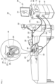
- Fig. 1 is a schematic view of a medical system 20 constructed and operative in accordance with an exemplary embodiment of the present invention.
- the system 20 includes a catheter 40 configured to be inserted into a body part of a living subject (e.g., a patient 28).
- a physician 30 navigates the catheter 40 (for example, a basket catheter produced Biosense Webster, Inc. of Irvine, CA, USA), to a target location in a heart 26 of the patient 28, by manipulating an elongated deflectable element 22 of the catheter 40, using a manipulator 32 near a proximal end of the catheter 40, and/or deflection from a sheath 23.
- physician 30 uses catheter 40 to perform electro-anatomical mapping of a cardiac chamber and ablation of cardiac tissue.
- Catheter 40 includes a plurality of electrodes 48 disposed on the expandable distal end assembly 35 for sensing electrical activity and/or applying ablation power to ablate tissue of the body part (inset 25).
- the catheter 40 also includes a proximal electrode 21 disposed on the deflectable element 22 proximal to the expandable distal end assembly 35.
- Catheter 40 may incorporate a magnetic position sensor (not shown) at the distal edge of deflectable element 22 (i.e., at the proximal edge of the distal end assembly 35).
- the magnetic sensor is a Single-Axis Sensor (SAS).
- SAS Single-Axis Sensor
- a second magnetic sensor (not shown) may be included at any suitable position on the assembly 35.
- the second magnetic sensor may be a Triple-Axis Sensor (TAS) or a Dual-Axis Sensor (DAS), or a SAS by way of example only, based for example on sizing considerations.
- TAS Triple-Axis Sensor
- DAS Dual-Axis Sensor
- SAS a SAS by way of example only, based for example on sizing considerations.
- the magnetic sensors, the proximal electrode 21, and electrodes 48 disposed on the assembly 35 are connected by wires running through deflectable element 22 to various driver circuitries in a console 24.
- system 20 comprises a magnetic-sensing subsystem to estimate an ellipticity of the basket assembly 35 of catheter 40, as well as its elongation/retraction state, inside a cardiac chamber of heart 26 by estimating the elongation of the basket assembly 35 from the distance between the magnetic sensors.
- Patient 28 is placed in a magnetic field generated by a pad containing one or more magnetic field generator coils 42, which are driven by a unit 43.
- the magnetic fields generated by coil(s) 42 transmit alternating magnetic fields into a region where the body-part is located.
- the transmitted alternating magnetic fields generate signals in the magnetic sensors, which are indicative of position and/or direction.
- the generated signals are transmitted to console 24 and become corresponding electrical inputs to processing circuitry 41.
- the method of position and/or direction sensing using external magnetic fields and magnetic sensors is implemented in various medical applications, for example, in the CARTO ® system, produced by Biosense-Webster, and is described in detail in U.S. Patent Nos. 5,391,199 , 6,690,963 , 6,484,118 , 6,239,724 , 6,618,612 and 6,332,089 , in PCT Patent Publication WO 96/05768 , and in U.S. Patent Application Publication Nos. 2002/0065455 A1 , 2003/0120150 A1 and 2004/0068178 A1 .
- Processing circuitry 41 is further connected via a suitable front end and interface circuits 44, to receive signals from body surface-electrodes 49.
- Processing circuitry 41 is connected to body surface-electrodes 49 by wires running through a cable 39 to the chest of patient 28.
- processing circuitry 41 renders to a display 27, a representation 31 of at least a part of the catheter 40 and a mapped body-part, responsively to computed position coordinates of the catheter 40.
- Processing circuitry 41 is typically programmed in software to carry out the functions described herein.
- the software may be downloaded to the computer in electronic form, over a network, for example, or it may, alternatively or additionally, be provided and/or stored on non-transitory tangible media, such as magnetic, optical, or electronic memory.
- the medical system 20 may also include an ablation power generator 69 (such as an RF signal generator) configured to be connected to the catheter 40, and apply an electrical signal between one or more of the electrodes 48 and the proximal electrode 21.
- the medical system 20 may also include an irrigation reservoir 71 configured to store irrigation fluid, and a pump 73 configured to be connected to the irrigation reservoir 71 and the catheter 40, and to pump the irrigation fluid from the irrigation reservoir 71 via an irrigation tube through irrigation holes of the catheter 40 as described in more detail with reference to Figs. 5A and 5B .
- the catheter 40 is configured to be inserted into a body part (e.g., the heart 26 ( Fig. 1 )) of a living subject.
- the deflectable element 22 of the catheter 40 has a distal end 33.
- the deflectable element 22 may be produced from any suitable material, for example, polyurethane or polyether block amide.
- the assembly 35 is disposed distally to the deflectable element 22 and may be connected to the deflectable element 22 via a proximal coupling member 50 at the distal end 33.
- the proximal coupling member 50 typically comprises a hollow tube and may be formed from any suitable material, for example, but not limited to polycarbonate with or without glass filler, polyether ether ketone (PEEK) with or without glass filler, polyimide, polyamide, or Polyetherimide (PEI) with or without glass filler.
- PEEK polyether ether ketone
- PEI Polyetherimide
- the coupling member 50 may formed as an integral part of the deflectable element 22 or as part of the distal end assembly 35 or as a separate element which connects with the deflectable element 22 and the distal end assembly 35.
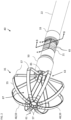
- the assembly 35 which may include a basket assembly, may include multiple splines such as flexible strips 55 (only one labeled for the sake of simplicity) with the electrodes 48 disposed on the splines.
- each flexible strip 55 includes a single electrode 48 (only some labeled for the sake of simplicity).
- the assembly 35 may include any suitable number of electrodes 48 with multiple electrodes 48 per strip 55.
- each flexible strip 55 is formed of Nitinol which is selectively covered with insulating material (for example, thermoplastic polymer resin shrink wrap (PET)) in the distal and proximal regions 57 (only some labeled for the sake of simplicity) of the flexible strips 55 leaving a central region 59 (only some labeled for the sake of simplicity) of the flexible strips 55 as an electrically active region to perform mapping and/or perform ablation or electroporation, by way of example.
- the structure of the assembly 35 may vary.
- flexible strips 55 (or other splines) may include flexible printed circuit boards (PCBs), or a shape-memory alloy such as Nitinol.
- the electrically active region of each flexible strip 55 may be larger or smaller than that shown in Fig. 2 , and/or more centrally or proximally disposed on each flexible strip 55.
- Embodiments described herein refer mainly to a basket distal-end assembly 35, purely by way of example. In alternative embodiments, the disclosed techniques can be used with any other suitable type of distal-end assembly.
- the distal end assembly 35 includes a distal portion 61, and a proximal portion 63, and is configured to expand from a collapsed form (shown in Fig. 3 ) to an expanded deployed form (shown in Fig. 2 ).
- the relaxed state of the distal end assembly 35 is the expanded deployed form shown in Fig. 2 .
- the distal end assembly 35 is configured to collapse into the collapsed form when the catheter 40 is retracted in a sheath 23 ( Fig. 1 ) and is configured to expand to the expanded deployed form when the catheter 40 is removed from the sheath 23.
- the relaxed shape of the distal end assembly 35 may be set by forming the flexible strips 55 from any suitable resilient material such as Nitinol or PEI.
- the relaxed state of the expandable distal end assembly 35 may be the collapsed form, and the expandable distal end assembly 35 is expanded using a pull wire or element connected to the distal portion 61 and fed through a lumen in the deflectable element 22.
- Fig. 4A is a cross-sectional view of the distal end of the catheter 40 of Fig. 2 .
- Fig. 4B is a more detailed cross-sectional view of the distal end of the catheter 40 inside block B of Fig. 4A .
- the catheter 40 may include another irrigation tube 85 disposed in the deflectable element 22 and configured to deliver irrigation fluid into a region 87 ( Fig. 2 ) surrounded by the flexible strips 55 of the expandable distal end assembly 35.
- the irrigation tube 85 typically extends into the expandable distal end assembly 35 as shown in Figs. 2 and 3 .
- the catheter 40 includes a position sensor 89 (such as a magnetic position sensor) disposed in the deflectable element 22.
- Figs. 5A and 5B also show wires 91 disposed therein connecting the electrodes 48, the proximal electrode 21, and the position sensor 89 with the proximal end of the catheter 40.
- Fig. 6 is a schematic view of a catheter 100 in a deployed form constructed and operative in accordance with an alternative embodiment of the present invention.
- the catheter 100 is substantially the same as the catheter 40 of Figs. 2 and 3 except for the following differences.
- the catheter 100 includes a proximal electrode 106, which is not irrigated.
- the proximal electrode 106 may either be cooled by filling with a thermally conductive material as described with reference to a proximal electrode 106-1 of Fig. 7 , or by forming the proximal electrode from a thermally conductive material of sufficient thickness to dissipate heat as described with reference to a proximal electrode 106-2 of Fig. 8 .
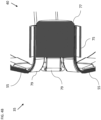
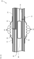
- Fig. 7 is a cross-sectional view of the catheter 100 of Fig. 6 along line C:C.
- the proximal electrode 106-1 and the distal end of the deflectable element 22 define an annular region 102 therebetween.
- the catheter 100 includes thermally conductive material 104, which is disposed in the annular region 102, generally, but not necessarily, filling the annular region 102, and generally in contact with at least part of the inner surface of the proximal electrode 106-1.
- the thermally conductive material 104 may be formed from a different material than the proximal electrode 106-1.
- the proximal electrode 106-1 is first fixed around the deflectable element 22 (as a single piece or from two halves subsequently joined together) and then the thermally conductive material 104 is injected below the proximal electrode 106-1 through a hole (not shown) in the proximal electrode 106-1.
- the wall thickness of the proximal electrode 106-1 may have any suitable value, for example, in the range of about 0.01mm to 0.25mm.
- the thickness of the thermally conductive material 104 may have any suitable value, for example, in the range of about 0.01mm to 0.25mm.
- the proximal electrode 106-1 may have any suitable length measured parallel to the direction of elongation of the deflectable element 22, for example, between about 2 mm and 10 mm.
- irrigation tube 81 ( Figs. 5A and 5B ) is not included within the deflectable element 22 shown in Fig. 7 .
- the proximal electrode 106-2 may have any suitable wall thickness.
- the proximal electrode 106-2 may have a maximum thickness measured perpendicular to the axis of the deflectable element 22 of at least 0.05 mm and an inner diameter in the range of 2 mm to 6 mm.
- the proximal electrode 106-2 may have any suitable length measured parallel to the direction of elongation of the deflectable element 22 of between about 2 mm and 10 mm.
- Each proximal electrode 106-2, 106-1 ( Fig. 7 ), 21 ( Figs. 5A and 5B ), has a non-uniform surface, which bulges away from the outer surface of the deflectable element 22.
- the proximal electrodes may have any suitable shape.
- the proximal electrode 21, 106-1, 106-2 may be formed as ring having a uniform outer diameter along the length of the proximal electrode 21.
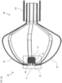
- Fig. 9 is a schematic view of a balloon catheter 200 in a deployed form constructed and operative in accordance with yet another alternative embodiment of the present invention.
- the catheter 200 is substantially the same as the catheter 40 of Fig. 2 except that the catheter 200 includes an expandable distal end assembly 202, which includes an inflatable balloon 204 with the electrodes 206 (only some labeled for the sake of simplicity) disposed thereon.
- the catheter 200 includes an irrigation tube 208 which is disposed in the deflectable element 22 and extends into a region 210 surrounded by the inflatable balloon 204.
- the electrodes 206 of the expandable distal end assembly 202 include irrigation holes 212 (only some labeled for the sake of simplicity) that are in fluid communication with the irrigation tube 208.
- the catheter 200 includes a proximal electrode 214 in substantially the same form as the proximal electrode 21 described with reference to Figs. 5A and 5B .
- the proximal electrode 214 may be replaced with the proximal electrode 106-1 of Fig. 7 or with the proximal electrode 106-2 of Fig. 8 .
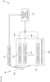
- Fig. 10 is a schematic view of electrode connections in the catheter 40 of medical system 20 constructed and operative in accordance with an exemplary embodiment of the present invention.
- the catheter 40 may include one or more electrical connections 230 configured to electrically connect together at least two (and optionally all) of the assembly electrodes 48 to act as a combined assembly electrode 232.
- the electrical connection(s) 230 may be configured to selectively connect together the assembly electrodes 48 to act as the combined assembly electrode 232 and also allow the electrodes 48 to act as individual electrodes, for example, for sensing positions, electrical activations, and performing individual ablation.
- the electrical connections 230 may include switching circuitry (not shown) which enables selectively connecting together two or more (and optionally all) of the assembly electrodes 48.
- the electrical connection(s) 230 permanently electrically connects together the at least two (and optionally all) of the assembly electrodes 48 to act as the combined assembly electrode 232.
- the ablation power generator 69 is configured to be connected to the catheter 40, and apply an electrical signal (arrow 234) to the combined assembly electrode 232 so as to ablate tissue of the body part. In some embodiments, the ablation power generator 69 is configured to apply the electrical signal 234 to the combined assembly electrode 48 so as to perform electroporation of tissue of the body part.
- the electrical signal 234 is generally applied between the combined assembly electrode 232 and a return electrode.
- the return electrode may be located in any suitable location, for example, on the catheter 40, as an indifferent electrode attached to the patient's skin or on another catheter.
- the proximal electrode 21 acts as the return electrode.
- the proximal electrode 21 may apply cooling to surrounding tissue using irrigation as described above with reference to Figs. 2 , 5A and 5B .
- two or more (and optionally all) of the assembly electrodes 48 ( Fig. 6 ) of the catheter 100 may be connected (selectively or permanently) using the electrical connections 230.
- the proximal electrode 106 ( Fig. 6 ) or any other suitable electrode may act as the return electrode.
- the proximal electrode 106 may provide cooling using the thermally conductive material 104 disposed in the annular region 102 ( Fig. 7 ) of the proximal electrode 106, as described in more detail above with reference to Fig. 7 .
- the proximal electrode 106 may provide cooling by forming the proximal electrode 106 ( Fig.
- two or more (and optionally all) of the electrodes 206 of the expandable distal end assembly 202 of the catheter 200 of Fig. 9 may be connected (selectively or permanently) using the electrical connections 230.
- the proximal electrode 214 ( Fig. 9 ) or any other suitable electrode may act as the return electrode.
- the terms “about” or “approximately” for any numerical values or ranges indicate a suitable dimensional tolerance that allows the part or collection of components to function for its intended purpose as described herein. More specifically, “about” or “approximately” may refer to the range of values ⁇ 20% of the recited value, e.g. "about 90%” may refer to the range of values from 72% to 108%.
Landscapes
- Health & Medical Sciences (AREA)
- Surgery (AREA)
- Engineering & Computer Science (AREA)
- Life Sciences & Earth Sciences (AREA)
- Biomedical Technology (AREA)
- Molecular Biology (AREA)
- Nuclear Medicine, Radiotherapy & Molecular Imaging (AREA)
- Plasma & Fusion (AREA)
- Physics & Mathematics (AREA)
- Heart & Thoracic Surgery (AREA)
- Medical Informatics (AREA)
- Otolaryngology (AREA)
- Animal Behavior & Ethology (AREA)
- General Health & Medical Sciences (AREA)
- Public Health (AREA)
- Veterinary Medicine (AREA)
- Cardiology (AREA)
- Surgical Instruments (AREA)
Claims (12)
- Medizinisches System (20), umfassend einen Katheter (40), der konfiguriert ist, um in einen Körperteil eines lebenden Subjekts eingeführt zu werden, und einschließlich:eines ablenkbaren Elements (22), das ein distales Ende (33) aufweist;einer erweiterbaren distalen Endanordnung (35), die an dem distalen Ende des ablenkbaren Elements eingerichtet ist und eine Vielzahl von Anordnungselektroden (48) umfasst und konfiguriert ist, um sich von einer zusammengeklappten Form in eine ausgedehnte entfaltete Form zu erweitern;einer proximalen Elektrode (21), die an dem distalen Ende des auslenkbaren Elements proximal zu der erweiterbaren distalen Endanordnung eingerichtet ist und sich kreisförmig um das auslenkbare Element herum erstreckt;mindestens einer elektrischen Verbindung (230), die konfiguriert ist, um mindestens zwei der Anordnungselektroden miteinander elektrisch zu verbinden, um als eine kombinierte Anordnungselektrode zu fungieren; undeines Ablationsstromgenerators (69), der konfiguriert ist, um mit dem Katheter verbunden zu sein und ein elektrisches Signal zwischen der kombinierten Anordnungselektrode und einer ausgewählten Elektrode anzulegen,dadurch gekennzeichnet, dass die proximale Elektrode und das distale Ende des ablenkbaren Elements dazwischen einen ringförmigen Bereich (102) definieren, wobei der Katheter außerdem wärmeleitendes Material (104) einschließt, das in dem ringförmigen Bereich eingerichtet ist, wobei das wärmeleitende Material aus einem anderen Material als die proximale Elektrode ausgebildet ist.
- System nach Anspruch 1, wobei die ausgewählte Elektrode die proximale Elektrode ist.
- System nach Anspruch 1, wobei die mindestens eine elektrische Verbindung die mindestens zwei Anordnungselektroden dauerhaft elektrisch miteinander verbindet, um als die kombinierte Anordnungselektrode zu fungieren.
- System nach Anspruch 1, wobei die proximale Elektrode Spüllöcher (65) einschließt, durch die der Körperteil gespült werden soll, wobei der Katheter außerdem einen Spülschlauch (81) einschließt, der in dem ablenkbaren Element eingerichtet und konfiguriert ist, um in Fluidkommunikation mit den Spüllöchern der proximalen Elektrode zu stehen.
- System nach Anspruch 4, wobei die Spüllöcher radial um die proximale Elektrode herum oder in Längsrichtung entlang der proximalen Elektrode eingerichtet sind.
- System nach Anspruch 4, wobei die proximale Elektrode und das ablenkbare Element einen ringförmigen Hohlraum (83) dazwischen definieren, wobei der Spülschlauch gekoppelt ist, um Spülfluid in den Hohlraum zu leiten, wobei der Spülschlauch über den Hohlraum in Fluidkommunikation mit den Spüllöchern steht.
- System nach Anspruch 4, ferner umfassend:ein Spülreservoir (71), das konfiguriert ist, um Spülfluid zu lagern; undeine Pumpe (73), die konfiguriert ist, um mit dem Spülreservoir und dem Katheter verbunden zu sein und um Spülfluid aus dem Spülreservoir über den Spülschlauch durch die Spüllöcher zu pumpen.
- System nach Anspruch 1, wobei der Ablationsstromgenerator konfiguriert ist, um das elektrische Signal zwischen der kombinierten Anordnungselektrode und der proximalen Elektrode anzulegen, um eine Elektroporation von Gewebe des Körperteils durchzuführen.
- System nach Anspruch 1, ferner umfassend einen Spülschlauch (85), der in dem ablenkbaren Element eingerichtet und konfiguriert ist, um Spülfluid in einen Bereich abzugeben, der von der erweiterbaren distalen Endanordnung umgeben ist.
- System nach Anspruch 1, wobei die proximale Elektrode eine maximale Dicke, die senkrecht zu der Achse des auslenkbaren Elements gemessen wird, von mindestens 0,05 mm und einen Innendurchmesser im Bereich von 2 mm bis 6 mm aufweist.
- System nach Anspruch 1, wobei die mindestens eine elektrische Verbindung alle Anordnungselektroden dauerhaft elektrisch miteinander verbindet, um als die kombinierte Anordnungselektrode zu fungieren.
- System nach Anspruch 1, wobei die erweiterbare distale Endanordnung mindestens eines einschließt von: einem erweiterbaren Korb, umfassend eine Vielzahl von Keilen (55), wobei die Elektroden auf den Keilen eingerichtet sind; oder einem aufblasbaren Ballon (204) mit darauf eingerichteten Elektroden.
Applications Claiming Priority (1)
| Application Number | Priority Date | Filing Date | Title |
|---|---|---|---|
| US17/029,552 US20220087736A1 (en) | 2020-09-23 | 2020-09-23 | Electrode shorting |
Publications (2)
| Publication Number | Publication Date |
|---|---|
| EP3973904A1 EP3973904A1 (de) | 2022-03-30 |
| EP3973904B1 true EP3973904B1 (de) | 2025-06-25 |
Family
ID=77897562
Family Applications (1)
| Application Number | Title | Priority Date | Filing Date |
|---|---|---|---|
| EP21198223.6A Active EP3973904B1 (de) | 2020-09-23 | 2021-09-22 | Elektrodenkurzschluss |
Country Status (5)
| Country | Link |
|---|---|
| US (1) | US20220087736A1 (de) |
| EP (1) | EP3973904B1 (de) |
| JP (1) | JP7707494B2 (de) |
| CN (1) | CN114246668A (de) |
| IL (1) | IL286513A (de) |
Families Citing this family (4)
| Publication number | Priority date | Publication date | Assignee | Title |
|---|---|---|---|---|
| US20250221764A1 (en) * | 2022-04-06 | 2025-07-10 | St. Jude Medical, Cardiology Division, Inc. | Hybrid mapping and pulsed field ablation catheter |
| US20240058073A1 (en) * | 2022-08-18 | 2024-02-22 | Biosense Webster (Israel) Ltd. | Multi-arm Catheter with Improved Magnetic Location Tracking |
| WO2024075034A1 (en) | 2022-10-05 | 2024-04-11 | Btl Medical Technologies S.R.O. | Pulsed field ablation device and method |
| US20240398351A1 (en) * | 2023-06-05 | 2024-12-05 | Biosense Webster (Israel) Ltd. | Medical probe end effector with hinges |
Citations (1)
| Publication number | Priority date | Publication date | Assignee | Title |
|---|---|---|---|---|
| US20160331459A1 (en) * | 2015-05-12 | 2016-11-17 | National University Of Ireland, Galway | Devices for therapeutic nasal neuromodulation and associated methods and systems |
Family Cites Families (35)
| Publication number | Priority date | Publication date | Assignee | Title |
|---|---|---|---|---|
| EP0706345B1 (de) | 1993-07-01 | 2003-02-19 | Boston Scientific Limited | Katheter zur bilddarstellung, zur anzeige elektrischer signale und zur ablation |
| US5860974A (en) * | 1993-07-01 | 1999-01-19 | Boston Scientific Corporation | Heart ablation catheter with expandable electrode and method of coupling energy to an electrode on a catheter shaft |
| US5391199A (en) | 1993-07-20 | 1995-02-21 | Biosense, Inc. | Apparatus and method for treating cardiac arrhythmias |
| CA2197986C (en) | 1994-08-19 | 2008-03-18 | Shlomo Ben-Haim | Medical diagnosis, treatment and imaging systems |
| US6690963B2 (en) | 1995-01-24 | 2004-02-10 | Biosense, Inc. | System for determining the location and orientation of an invasive medical instrument |
| CA2246287C (en) | 1996-02-15 | 2006-10-24 | Biosense, Inc. | Medical procedures and apparatus using intrabody probes |
| IL125761A (en) | 1996-02-15 | 2005-05-17 | Biosense Inc | Independently positionable transducers for location system |
| US6239724B1 (en) | 1997-12-30 | 2001-05-29 | Remon Medical Technologies, Ltd. | System and method for telemetrically providing intrabody spatial position |
| US6484118B1 (en) | 2000-07-20 | 2002-11-19 | Biosense, Inc. | Electromagnetic position single axis system |
| US7729742B2 (en) | 2001-12-21 | 2010-06-01 | Biosense, Inc. | Wireless position sensor |
| US6980858B2 (en) * | 2001-12-31 | 2005-12-27 | Biosense Webster, Inc. | Method and system for atrial defibrillation |
| US7653438B2 (en) * | 2002-04-08 | 2010-01-26 | Ardian, Inc. | Methods and apparatus for renal neuromodulation |
| US20040068178A1 (en) | 2002-09-17 | 2004-04-08 | Assaf Govari | High-gradient recursive locating system |
| US9713730B2 (en) * | 2004-09-10 | 2017-07-25 | Boston Scientific Scimed, Inc. | Apparatus and method for treatment of in-stent restenosis |
| ES2560006T3 (es) * | 2006-10-18 | 2016-02-17 | Vessix Vascular, Inc. | Inducción de efectos de temperatura deseables sobre tejido corporal |
| US8103327B2 (en) * | 2007-12-28 | 2012-01-24 | Rhythmia Medical, Inc. | Cardiac mapping catheter |
| AU2009314159B2 (en) | 2008-11-11 | 2016-04-14 | Shifamed Holdings, Llc | Low profile electrode assembly |
| US9795442B2 (en) | 2008-11-11 | 2017-10-24 | Shifamed Holdings, Llc | Ablation catheters |
| US9220433B2 (en) * | 2011-06-30 | 2015-12-29 | Biosense Webster (Israel), Ltd. | Catheter with variable arcuate distal section |
| US9125668B2 (en) * | 2011-09-14 | 2015-09-08 | Boston Scientific Scimed Inc. | Ablation device with multiple ablation modes |
| US9717555B2 (en) * | 2012-05-14 | 2017-08-01 | Biosense Webster (Israel), Ltd. | Catheter with helical end section for vessel ablation |
| WO2014110579A1 (en) | 2013-01-14 | 2014-07-17 | Boston Scientific Scimed, Inc. | Renal nerve ablation catheter |
| EP3073908B1 (de) * | 2014-02-25 | 2019-04-10 | St. Jude Medical, Cardiology Division, Inc. | Systeme und verfahren zur verwendung elektrophysiologischer eigenschaften zur klassifizierung von arrhythmiequellen |
| EP3139997B1 (de) * | 2014-05-07 | 2018-09-19 | Farapulse, Inc. | Vorrichtung zur selektiven gewebeablation |
| CN106714719A (zh) * | 2014-09-15 | 2017-05-24 | 导管治疗有限公司 | 冲洗式消融导管及其加工方法 |
| US10575742B2 (en) * | 2015-06-30 | 2020-03-03 | Biosense Webster (Israel) Ltd. | Catheter having closed electrode assembly with spines of uniform length |
| US10363090B2 (en) * | 2016-01-05 | 2019-07-30 | Biosense Webster (Israel) Ltd. | Catheter with flow diverter and force sensor |
| US10172673B2 (en) * | 2016-01-05 | 2019-01-08 | Farapulse, Inc. | Systems devices, and methods for delivery of pulsed electric field ablative energy to endocardial tissue |
| EP3451961B1 (de) * | 2016-05-02 | 2024-12-04 | Affera, Inc. | System umfassend einen katheter und eine expandierbare elektrode |
| US20180125576A1 (en) | 2016-11-09 | 2018-05-10 | Biosense Webster (Israel) Ltd. | Multi-electrode catheter for preventing physiological fluid flow restriction |
| US20180161093A1 (en) * | 2016-12-08 | 2018-06-14 | Biosense Webster (Israel) Ltd. | Irrigated balloon catheter with support spines and variable shape |
| EP3576657B1 (de) | 2017-04-10 | 2024-06-05 | St. Jude Medical, Cardiology Division, Inc. | Elektroporationssystem |
| EP3658050B1 (de) * | 2017-07-25 | 2023-09-06 | Affera, Inc. | Ablationskatheter |
| JP7586706B2 (ja) * | 2017-09-12 | 2024-11-19 | ボストン サイエンティフィック サイムド,インコーポレイテッド | 心室フォーカルアブレーションのためのシステム、装置、及び方法 |
| US12042216B2 (en) * | 2019-12-09 | 2024-07-23 | Biosense Webster (Israel) Ltd. | Irreversible-electroporation (IRE) balloon catheter with membrane-insulated high-voltage balloon wires |
-
2020
- 2020-09-23 US US17/029,552 patent/US20220087736A1/en active Pending
-
2021
- 2021-04-01 CN CN202110355673.9A patent/CN114246668A/zh active Pending
- 2021-09-19 IL IL286513A patent/IL286513A/en unknown
- 2021-09-22 JP JP2021154023A patent/JP7707494B2/ja active Active
- 2021-09-22 EP EP21198223.6A patent/EP3973904B1/de active Active
Patent Citations (1)
| Publication number | Priority date | Publication date | Assignee | Title |
|---|---|---|---|---|
| US20160331459A1 (en) * | 2015-05-12 | 2016-11-17 | National University Of Ireland, Galway | Devices for therapeutic nasal neuromodulation and associated methods and systems |
Also Published As
| Publication number | Publication date |
|---|---|
| CN114246668A (zh) | 2022-03-29 |
| US20220087736A1 (en) | 2022-03-24 |
| JP7707494B2 (ja) | 2025-07-15 |
| JP2022052757A (ja) | 2022-04-04 |
| IL286513A (en) | 2022-04-01 |
| EP3973904A1 (de) | 2022-03-30 |
Similar Documents
| Publication | Publication Date | Title |
|---|---|---|
| JP7654458B2 (ja) | 伸縮性灌注管を有するカテーテル | |
| EP3973904B1 (de) | Elektrodenkurzschluss | |
| US20220071695A1 (en) | Flex Circuit and Surface Mounted Electrode Catheter | |
| RU2762988C1 (ru) | Применение абляции путем необратимой электропорации (нэп) с использованием катетера с матрицей электродов | |
| JP7703420B2 (ja) | バルーンを備えるバスケット型カテーテル | |
| EP3861954A1 (de) | Ein bewässerter ballonkatheter mit flexibler schaltungselektrodenanordnung | |
| CN109199578A (zh) | 利用多个电极的温度控制的短持续时间消融 | |
| EP3960107B1 (de) | Kühlung von proximalen elektroden | |
| EP3932354B1 (de) | Elektroporation mit kühlung | |
| EP4205678A1 (de) | Katheterballon mit erhöhter elastizität gegenüber interner druckbeaufschlagung |
Legal Events
| Date | Code | Title | Description |
|---|---|---|---|
| PUAI | Public reference made under article 153(3) epc to a published international application that has entered the european phase |
Free format text: ORIGINAL CODE: 0009012 |
|
| STAA | Information on the status of an ep patent application or granted ep patent |
Free format text: STATUS: THE APPLICATION HAS BEEN PUBLISHED |
|
| AK | Designated contracting states |
Kind code of ref document: A1 Designated state(s): AL AT BE BG CH CY CZ DE DK EE ES FI FR GB GR HR HU IE IS IT LI LT LU LV MC MK MT NL NO PL PT RO RS SE SI SK SM TR |
|
| STAA | Information on the status of an ep patent application or granted ep patent |
Free format text: STATUS: REQUEST FOR EXAMINATION WAS MADE |
|
| 17P | Request for examination filed |
Effective date: 20220810 |
|
| RBV | Designated contracting states (corrected) |
Designated state(s): AL AT BE BG CH CY CZ DE DK EE ES FI FR GB GR HR HU IE IS IT LI LT LU LV MC MK MT NL NO PL PT RO RS SE SI SK SM TR |
|
| STAA | Information on the status of an ep patent application or granted ep patent |
Free format text: STATUS: EXAMINATION IS IN PROGRESS |
|
| 17Q | First examination report despatched |
Effective date: 20241107 |
|
| GRAP | Despatch of communication of intention to grant a patent |
Free format text: ORIGINAL CODE: EPIDOSNIGR1 |
|
| STAA | Information on the status of an ep patent application or granted ep patent |
Free format text: STATUS: GRANT OF PATENT IS INTENDED |
|
| INTG | Intention to grant announced |
Effective date: 20250326 |
|
| GRAS | Grant fee paid |
Free format text: ORIGINAL CODE: EPIDOSNIGR3 |
|
| GRAA | (expected) grant |
Free format text: ORIGINAL CODE: 0009210 |
|
| STAA | Information on the status of an ep patent application or granted ep patent |
Free format text: STATUS: THE PATENT HAS BEEN GRANTED |
|
| AK | Designated contracting states |
Kind code of ref document: B1 Designated state(s): AL AT BE BG CH CY CZ DE DK EE ES FI FR GB GR HR HU IE IS IT LI LT LU LV MC MK MT NL NO PL PT RO RS SE SI SK SM TR |
|
| REG | Reference to a national code |
Ref country code: GB Ref legal event code: FG4D |
|
| REG | Reference to a national code |
Ref country code: CH Ref legal event code: EP |
|
| REG | Reference to a national code |
Ref country code: CH Ref legal event code: EP |
|
| REG | Reference to a national code |
Ref country code: IE Ref legal event code: FG4D |
|
| REG | Reference to a national code |
Ref country code: DE Ref legal event code: R096 Ref document number: 602021032733 Country of ref document: DE |
|
| PG25 | Lapsed in a contracting state [announced via postgrant information from national office to epo] |
Ref country code: FI Free format text: LAPSE BECAUSE OF FAILURE TO SUBMIT A TRANSLATION OF THE DESCRIPTION OR TO PAY THE FEE WITHIN THE PRESCRIBED TIME-LIMIT Effective date: 20250625 |
|
| REG | Reference to a national code |
Ref country code: LT Ref legal event code: MG9D |
|
| PG25 | Lapsed in a contracting state [announced via postgrant information from national office to epo] |
Ref country code: GR Free format text: LAPSE BECAUSE OF FAILURE TO SUBMIT A TRANSLATION OF THE DESCRIPTION OR TO PAY THE FEE WITHIN THE PRESCRIBED TIME-LIMIT Effective date: 20250926 Ref country code: NO Free format text: LAPSE BECAUSE OF FAILURE TO SUBMIT A TRANSLATION OF THE DESCRIPTION OR TO PAY THE FEE WITHIN THE PRESCRIBED TIME-LIMIT Effective date: 20250925 |
|
| PG25 | Lapsed in a contracting state [announced via postgrant information from national office to epo] |
Ref country code: BG Free format text: LAPSE BECAUSE OF FAILURE TO SUBMIT A TRANSLATION OF THE DESCRIPTION OR TO PAY THE FEE WITHIN THE PRESCRIBED TIME-LIMIT Effective date: 20250625 |
|
| PGFP | Annual fee paid to national office [announced via postgrant information from national office to epo] |
Ref country code: GB Payment date: 20250807 Year of fee payment: 5 |
|
| PG25 | Lapsed in a contracting state [announced via postgrant information from national office to epo] |
Ref country code: HR Free format text: LAPSE BECAUSE OF FAILURE TO SUBMIT A TRANSLATION OF THE DESCRIPTION OR TO PAY THE FEE WITHIN THE PRESCRIBED TIME-LIMIT Effective date: 20250625 |
|
| PGFP | Annual fee paid to national office [announced via postgrant information from national office to epo] |
Ref country code: AT Payment date: 20251020 Year of fee payment: 5 |
|
| PG25 | Lapsed in a contracting state [announced via postgrant information from national office to epo] |
Ref country code: RS Free format text: LAPSE BECAUSE OF FAILURE TO SUBMIT A TRANSLATION OF THE DESCRIPTION OR TO PAY THE FEE WITHIN THE PRESCRIBED TIME-LIMIT Effective date: 20250925 |
|
| PG25 | Lapsed in a contracting state [announced via postgrant information from national office to epo] |
Ref country code: LV Free format text: LAPSE BECAUSE OF FAILURE TO SUBMIT A TRANSLATION OF THE DESCRIPTION OR TO PAY THE FEE WITHIN THE PRESCRIBED TIME-LIMIT Effective date: 20250625 |
|
| REG | Reference to a national code |
Ref country code: NL Ref legal event code: MP Effective date: 20250625 |
|
| PG25 | Lapsed in a contracting state [announced via postgrant information from national office to epo] |
Ref country code: NL Free format text: LAPSE BECAUSE OF FAILURE TO SUBMIT A TRANSLATION OF THE DESCRIPTION OR TO PAY THE FEE WITHIN THE PRESCRIBED TIME-LIMIT Effective date: 20250625 |
|
| PG25 | Lapsed in a contracting state [announced via postgrant information from national office to epo] |
Ref country code: PT Free format text: LAPSE BECAUSE OF FAILURE TO SUBMIT A TRANSLATION OF THE DESCRIPTION OR TO PAY THE FEE WITHIN THE PRESCRIBED TIME-LIMIT Effective date: 20251027 |
|
| REG | Reference to a national code |
Ref country code: AT Ref legal event code: MK05 Ref document number: 1805660 Country of ref document: AT Kind code of ref document: T Effective date: 20250625 |
|
| PG25 | Lapsed in a contracting state [announced via postgrant information from national office to epo] |
Ref country code: IS Free format text: LAPSE BECAUSE OF FAILURE TO SUBMIT A TRANSLATION OF THE DESCRIPTION OR TO PAY THE FEE WITHIN THE PRESCRIBED TIME-LIMIT Effective date: 20251025 |
|
| PG25 | Lapsed in a contracting state [announced via postgrant information from national office to epo] |
Ref country code: AT Free format text: LAPSE BECAUSE OF FAILURE TO SUBMIT A TRANSLATION OF THE DESCRIPTION OR TO PAY THE FEE WITHIN THE PRESCRIBED TIME-LIMIT Effective date: 20250625 Ref country code: SM Free format text: LAPSE BECAUSE OF FAILURE TO SUBMIT A TRANSLATION OF THE DESCRIPTION OR TO PAY THE FEE WITHIN THE PRESCRIBED TIME-LIMIT Effective date: 20250625 |
|
| PG25 | Lapsed in a contracting state [announced via postgrant information from national office to epo] |
Ref country code: CZ Free format text: LAPSE BECAUSE OF FAILURE TO SUBMIT A TRANSLATION OF THE DESCRIPTION OR TO PAY THE FEE WITHIN THE PRESCRIBED TIME-LIMIT Effective date: 20250625 |
|
| PG25 | Lapsed in a contracting state [announced via postgrant information from national office to epo] |
Ref country code: PL Free format text: LAPSE BECAUSE OF FAILURE TO SUBMIT A TRANSLATION OF THE DESCRIPTION OR TO PAY THE FEE WITHIN THE PRESCRIBED TIME-LIMIT Effective date: 20250625 |
|
| PG25 | Lapsed in a contracting state [announced via postgrant information from national office to epo] |
Ref country code: EE Free format text: LAPSE BECAUSE OF FAILURE TO SUBMIT A TRANSLATION OF THE DESCRIPTION OR TO PAY THE FEE WITHIN THE PRESCRIBED TIME-LIMIT Effective date: 20250625 |
|
| PG25 | Lapsed in a contracting state [announced via postgrant information from national office to epo] |
Ref country code: SK Free format text: LAPSE BECAUSE OF FAILURE TO SUBMIT A TRANSLATION OF THE DESCRIPTION OR TO PAY THE FEE WITHIN THE PRESCRIBED TIME-LIMIT Effective date: 20250625 |
|
| PG25 | Lapsed in a contracting state [announced via postgrant information from national office to epo] |
Ref country code: ES Free format text: LAPSE BECAUSE OF FAILURE TO SUBMIT A TRANSLATION OF THE DESCRIPTION OR TO PAY THE FEE WITHIN THE PRESCRIBED TIME-LIMIT Effective date: 20250625 |
|
| PG25 | Lapsed in a contracting state [announced via postgrant information from national office to epo] |
Ref country code: RO Free format text: LAPSE BECAUSE OF FAILURE TO SUBMIT A TRANSLATION OF THE DESCRIPTION OR TO PAY THE FEE WITHIN THE PRESCRIBED TIME-LIMIT Effective date: 20250625 |