EP3973893A1 - Inverting braided aneurysm implant with dome feature - Google Patents
Inverting braided aneurysm implant with dome feature Download PDFInfo
- Publication number
- EP3973893A1 EP3973893A1 EP21198510.6A EP21198510A EP3973893A1 EP 3973893 A1 EP3973893 A1 EP 3973893A1 EP 21198510 A EP21198510 A EP 21198510A EP 3973893 A1 EP3973893 A1 EP 3973893A1
- Authority
- EP
- European Patent Office
- Prior art keywords
- implant
- braided segment
- braided
- segment
- shape
- Prior art date
- Legal status (The legal status is an assumption and is not a legal conclusion. Google has not performed a legal analysis and makes no representation as to the accuracy of the status listed.)
- Withdrawn
Links
- 239000007943 implant Substances 0.000 title claims abstract description 194
- 206010002329 Aneurysm Diseases 0.000 title abstract description 143
- 238000000034 method Methods 0.000 claims description 49
- 238000007493 shaping process Methods 0.000 claims description 14
- 230000006835 compression Effects 0.000 claims description 3
- 238000007906 compression Methods 0.000 claims description 3
- 230000003073 embolic effect Effects 0.000 abstract description 28
- 239000010410 layer Substances 0.000 description 29
- 238000011282 treatment Methods 0.000 description 18
- 239000000463 material Substances 0.000 description 9
- 230000001732 thrombotic effect Effects 0.000 description 5
- 230000017531 blood circulation Effects 0.000 description 4
- 210000004204 blood vessel Anatomy 0.000 description 4
- 238000005056 compaction Methods 0.000 description 4
- 230000006870 function Effects 0.000 description 4
- 238000004873 anchoring Methods 0.000 description 3
- 239000008280 blood Substances 0.000 description 3
- 210000004369 blood Anatomy 0.000 description 3
- 238000012986 modification Methods 0.000 description 2
- 230000004048 modification Effects 0.000 description 2
- 238000012856 packing Methods 0.000 description 2
- 239000002356 single layer Substances 0.000 description 2
- 210000005166 vasculature Anatomy 0.000 description 2
- 201000002282 venous insufficiency Diseases 0.000 description 2
- 206010000060 Abdominal distension Diseases 0.000 description 1
- 208000022211 Arteriovenous Malformations Diseases 0.000 description 1
- 241000722921 Tulipa gesneriana Species 0.000 description 1
- 239000000853 adhesive Substances 0.000 description 1
- 230000001070 adhesive effect Effects 0.000 description 1
- 230000002411 adverse Effects 0.000 description 1
- 210000003484 anatomy Anatomy 0.000 description 1
- 230000005744 arteriovenous malformation Effects 0.000 description 1
- 230000015572 biosynthetic process Effects 0.000 description 1
- 230000000903 blocking effect Effects 0.000 description 1
- 210000005013 brain tissue Anatomy 0.000 description 1
- 230000000694 effects Effects 0.000 description 1
- 230000008030 elimination Effects 0.000 description 1
- 238000003379 elimination reaction Methods 0.000 description 1
- 230000035876 healing Effects 0.000 description 1
- 238000002513 implantation Methods 0.000 description 1
- 230000001939 inductive effect Effects 0.000 description 1
- 239000003550 marker Substances 0.000 description 1
- 238000005259 measurement Methods 0.000 description 1
- 230000006833 reintegration Effects 0.000 description 1
- 238000002560 therapeutic procedure Methods 0.000 description 1
Images





Classifications
-
- A—HUMAN NECESSITIES
- A61—MEDICAL OR VETERINARY SCIENCE; HYGIENE
- A61B—DIAGNOSIS; SURGERY; IDENTIFICATION
- A61B17/00—Surgical instruments, devices or methods
- A61B17/12—Surgical instruments, devices or methods for ligaturing or otherwise compressing tubular parts of the body, e.g. blood vessels or umbilical cord
- A61B17/12022—Occluding by internal devices, e.g. balloons or releasable wires
- A61B17/12099—Occluding by internal devices, e.g. balloons or releasable wires characterised by the location of the occluder
- A61B17/12109—Occluding by internal devices, e.g. balloons or releasable wires characterised by the location of the occluder in a blood vessel
- A61B17/12113—Occluding by internal devices, e.g. balloons or releasable wires characterised by the location of the occluder in a blood vessel within an aneurysm
-
- A—HUMAN NECESSITIES
- A61—MEDICAL OR VETERINARY SCIENCE; HYGIENE
- A61B—DIAGNOSIS; SURGERY; IDENTIFICATION
- A61B17/00—Surgical instruments, devices or methods
- A61B17/12—Surgical instruments, devices or methods for ligaturing or otherwise compressing tubular parts of the body, e.g. blood vessels or umbilical cord
- A61B17/12022—Occluding by internal devices, e.g. balloons or releasable wires
- A61B17/12027—Type of occlusion
- A61B17/12031—Type of occlusion complete occlusion
-
- A—HUMAN NECESSITIES
- A61—MEDICAL OR VETERINARY SCIENCE; HYGIENE
- A61B—DIAGNOSIS; SURGERY; IDENTIFICATION
- A61B17/00—Surgical instruments, devices or methods
- A61B17/12—Surgical instruments, devices or methods for ligaturing or otherwise compressing tubular parts of the body, e.g. blood vessels or umbilical cord
- A61B17/12022—Occluding by internal devices, e.g. balloons or releasable wires
- A61B17/12131—Occluding by internal devices, e.g. balloons or releasable wires characterised by the type of occluding device
- A61B17/1214—Coils or wires
-
- A—HUMAN NECESSITIES
- A61—MEDICAL OR VETERINARY SCIENCE; HYGIENE
- A61B—DIAGNOSIS; SURGERY; IDENTIFICATION
- A61B17/00—Surgical instruments, devices or methods
- A61B17/12—Surgical instruments, devices or methods for ligaturing or otherwise compressing tubular parts of the body, e.g. blood vessels or umbilical cord
- A61B17/12022—Occluding by internal devices, e.g. balloons or releasable wires
- A61B17/12131—Occluding by internal devices, e.g. balloons or releasable wires characterised by the type of occluding device
- A61B17/12168—Occluding by internal devices, e.g. balloons or releasable wires characterised by the type of occluding device having a mesh structure
-
- A—HUMAN NECESSITIES
- A61—MEDICAL OR VETERINARY SCIENCE; HYGIENE
- A61B—DIAGNOSIS; SURGERY; IDENTIFICATION
- A61B17/00—Surgical instruments, devices or methods
- A61B17/12—Surgical instruments, devices or methods for ligaturing or otherwise compressing tubular parts of the body, e.g. blood vessels or umbilical cord
- A61B17/12022—Occluding by internal devices, e.g. balloons or releasable wires
- A61B17/12131—Occluding by internal devices, e.g. balloons or releasable wires characterised by the type of occluding device
- A61B17/12168—Occluding by internal devices, e.g. balloons or releasable wires characterised by the type of occluding device having a mesh structure
- A61B17/12172—Occluding by internal devices, e.g. balloons or releasable wires characterised by the type of occluding device having a mesh structure having a pre-set deployed three-dimensional shape
-
- A—HUMAN NECESSITIES
- A61—MEDICAL OR VETERINARY SCIENCE; HYGIENE
- A61L—METHODS OR APPARATUS FOR STERILISING MATERIALS OR OBJECTS IN GENERAL; DISINFECTION, STERILISATION OR DEODORISATION OF AIR; CHEMICAL ASPECTS OF BANDAGES, DRESSINGS, ABSORBENT PADS OR SURGICAL ARTICLES; MATERIALS FOR BANDAGES, DRESSINGS, ABSORBENT PADS OR SURGICAL ARTICLES
- A61L31/00—Materials for other surgical articles, e.g. stents, stent-grafts, shunts, surgical drapes, guide wires, materials for adhesion prevention, occluding devices, surgical gloves, tissue fixation devices
- A61L31/14—Materials characterised by their function or physical properties, e.g. injectable or lubricating compositions, shape-memory materials, surface modified materials
- A61L31/18—Materials at least partially X-ray or laser opaque
-
- A—HUMAN NECESSITIES
- A61—MEDICAL OR VETERINARY SCIENCE; HYGIENE
- A61B—DIAGNOSIS; SURGERY; IDENTIFICATION
- A61B17/00—Surgical instruments, devices or methods
- A61B2017/00526—Methods of manufacturing
-
- A—HUMAN NECESSITIES
- A61—MEDICAL OR VETERINARY SCIENCE; HYGIENE
- A61B—DIAGNOSIS; SURGERY; IDENTIFICATION
- A61B17/00—Surgical instruments, devices or methods
- A61B2017/00831—Material properties
- A61B2017/00867—Material properties shape memory effect
-
- A—HUMAN NECESSITIES
- A61—MEDICAL OR VETERINARY SCIENCE; HYGIENE
- A61B—DIAGNOSIS; SURGERY; IDENTIFICATION
- A61B17/00—Surgical instruments, devices or methods
- A61B2017/00831—Material properties
- A61B2017/00902—Material properties transparent or translucent
- A61B2017/00915—Material properties transparent or translucent for radioactive radiation
- A61B2017/0092—Material properties transparent or translucent for radioactive radiation for X-rays
-
- A—HUMAN NECESSITIES
- A61—MEDICAL OR VETERINARY SCIENCE; HYGIENE
- A61B—DIAGNOSIS; SURGERY; IDENTIFICATION
- A61B17/00—Surgical instruments, devices or methods
- A61B17/12—Surgical instruments, devices or methods for ligaturing or otherwise compressing tubular parts of the body, e.g. blood vessels or umbilical cord
- A61B17/12022—Occluding by internal devices, e.g. balloons or releasable wires
- A61B2017/1205—Introduction devices
Definitions
- the present invention generally relates to medical instruments, and more particularly, to embolic implants for aneurysm therapy.
- Cranial aneurysms can be complicated and difficult to treat due to their proximity to critical brain tissues.
- Current treatments can involve intravascularly delivering embolic coils that fill the sac of the aneurysm or block the entrance or neck of the aneurysm to prevent blood flow into the aneurysm.
- embolic coils When filling an aneurysm sac, the embolic coils clots the blood, creating a thrombotic mass within the aneurysm.
- blood flow into the entrance of the aneurysm is inhibited, inducing venous stasis in the aneurysm and facilitating a natural formation of a thrombotic mass within the aneurysm.
- Naturally formed thrombotic masses can result in improved healing compared to aneurysm masses packed with embolic material because naturally formed thrombotic masses can reduce the likelihood of distention from arterial walls and facilitate reintegration into the original parent vessel shape along the neck plane.
- properly placing embolic coils across the aneurysm neck can be challenging. Embolic coils delivered to the neck of the aneurysm can potentially have the adverse effect of impeding the flow of blood in the adjoining blood vessel, particularly if the entrance is overpacked. Conversely, if the entrance is insufficiently packed, blood flow can persist into the aneurysm.
- treating certain aneurysm morphology e.g.
- embolic coils do not always effectively treat aneurysms as aneurysms treated with multiple coils often recanalize or compact because of poor coiling, lack of coverage across the aneurysm neck, blood flow, or large aneurysm size.
- Tubular braided implants have the potential to easily, accurately, and safely treat an aneurysm or other arterio-venous malformation in a parent vessel without blocking flow into perforator vessels communicating with the parent vessel.
- a tubular braided implant that can be used in addition to, or as an alternative to embolic coil treatments of aneurysms is disclosed in U.S. Pat. No. 10,653,425 , incorporated herein by reference.
- Example implants presented herein can be implanted in an aneurysm to cause thrombogenesis within the aneurysm's sac.
- Example implants include a braid that can extend across the aneurysm neck and anchor to aneurysm's walls at least in the proximal portion of the aneurysm sac.
- Example implants can further include a dome feature configured to press into aneurysm walls near the aneurysm's dome at a distal portion of the aneurysm sac.
- the braid at the aneurysm's neck and the dome feature can be joined or constricted at a junction.
- the dome feature can facilitate proper anchoring of the braid across the aneurysm's neck.
- Various examples of implants having variations in dome features and variations in braided portions are presented herein. The dome features and braided portions are interchangeable between examples.
- An example implant can include a first braided segment, a second braided segment, and a band.
- the example implant can be shaped to have a predetermined shape.
- the first braided segment can include a distal open end.
- the second braided segment can include a proximal pinched end.
- the band can be positioned at a junction between the first braided segment and the second braided segment.
- the band can constrict the first braided segment and the second braided segment at the junction.
- the first braided segment can function as a dome feature and the second braided segment can be positioned across an aneurysm neck.
- the first braided segment can extend in a distal direction from the band and form a bowl shape.
- the second braided segment can extend in a proximal direction from the band.
- the second braided segment can include two inversions separating three sections which at least partially overlap each other such that the pinched end is affixed to an innermost section of the three sections, the band is affixed to an outermost section of the three sections, and a middle section of the three sections extends between the two inversions and is positioned within outermost section and around the innermost section.
- the entirety of the first braided segment of the implant can be positioned in the distal direction from the entirety of the second braided segment of the implant.
- the band and the pinched end can be approximately aligned along a longitudinal axis.
- the first braided segment and the second braided segment can be respectively approximately radially symmetrical with respect to the longitudinal axis.
- the implant can be collapsible to a dimension sized to traverse a microcatheter within neurovasculature.
- the implant can be configured to be manipulated at the pinched end to position the implant in an implanted shape in a spherical cavity.
- the implanted shape can be based in part on the predetermined shape and based in part on the geometry of the spherical cavity.
- the first braided section can provide a force pressing the second braided section in the proximal direction due to compression of the first braided section against a dome of the spherical cavity.
- the open end can be positioned approximate a distal wall of the spherical cavity, the band can be suspended within the spherical cavity, and the second braided segment can include two inversions separating three sections which at least partially overlap each other.
- the two inversions and the three sections of the second braided segment when the implant is in the implanted shape can correspond approximately to the two inversions and the three sections of the second braided segment when the implant is in the predetermined shape.
- a diameter of the open end is collapsed in comparison to the diameter of the open end when the implant is in the predetermined shape.
- a height of the first segment is foreshortened in comparison to the height of the first segment when the implant is in the predetermined shape.
- the open end can include closed looped braid strands.
- the band can include radiopaque material.
- the implant can be stable in two different implanted shapes, where the stable shape that the implant takes can be selected during treatment to fit within a smaller or larger spherical cavity.
- the implant can be stable in a first implanted shape based on the predetermined shape when constrained by a first substantially spherical cavity.
- the implant can be stable in a second implanted shape based on the predetermined shape when constrained by a second substantially spherical cavity smaller than the first substantially spherical cavity,
- the open end is positioned approximate a distal wall of the first substantially spherical cavity, the band is suspended within the first substantially spherical cavity, and the second braided segment includes two inversions separating three sections which at least partially overlap each other.
- the two inversions and the three sections of the second braided segment when the implant is in the first implanted shape correspond approximately to the two inversions and the three sections of the second braided segment when the implant is in the predetermined shape.
- the open end is positioned approximate a distal wall of the second substantially spherical cavity, the band is suspended within the second substantially spherical cavity, and the second braided segment includes two inversions separating three sections which at least partially overlap each other.
- One of the two inversions, when the implant is in the second implanted shape, corresponds to a bend in the middle section when the implant is in the predetermined shape.
- An example method for constructing an implant can include one or more of the following steps presented in no particular order, and the method can include additional steps not included here.
- a band can be affixed between a first braided segment and a second braided segment, the first braided segment including a distal open end and the second braided segment including a proximal pinched end.
- the implant can be shaped to a predetermined shape to which the implant is capable of self-expanding.
- Shaping the implant to the predetermined shape can include: forming the first braided segment to a bowl shape extending in a distal direction from the band; inverting the second braided segment to form a proximal inversion folded toward the distal direction thereby defining an outermost section of the second braided segment; and inverting the second braided segment to form a distal inversion folded toward the proximal direction thereby defining a middle section between the proximal and distal inversions of the second braided segment that is at least partially surrounded by the outermost section and defining an innermost section between the distal inversion and the pinched end that is at least partially surrounded by the middle section.
- the method can further include shaping the implant to the predetermined shape such that when the implant is in the predetermined shape, the entirety of the first braided segment is positioned in the distal direction from the entirety of the second braided segment.
- the method can further include shaping the implant to the predetermined shape such that when the implant is in the predetermined shape, the band and the pinched end are approximately aligned along a longitudinal axis and the first braided segment and the second braided segment are respectively approximately radially symmetrical with respect to the longitudinal axis.
- the method can further include collapsing the implant and positioning the implant in a microcatheter sized to traverse neurovasculature.
- the method can further include affixing a delivery system to the implant approximate the pinched end so that the pinched end can be manipulated to move the implant from a distal end of the microcatheter.
- the method can further include forming a bend in the middle section of the second braided segment that is configured to fold to form an inversion when the implant is positioned, via manipulation of the pinched end, in a substantially spherical cavity.
- An example method of treating an aneurysm can include one or more of the following steps presented in no particular order, and the method can include additional steps not included here.
- An open end of a first braided segment of an implant can be pushed from a distal end of a microcatheter into a sac of an aneurysm.
- the first braided segment can be shaped to form a distal sack positioned against a dome of the aneurysm and extending centrally through the sac to a band affixed to the first braided segment.
- An outer section of a second braided segment of the implant can be shaped to form proximal sack extending centrally through the sac from the band, positioned against a portion of the aneurysm wall in a proximal direction from the distal sack, and extending across at least a portion of a neck opening of the aneurysm.
- the second braided segment can be inverted approximate the neck opening of the aneurysm.
- the second braided segment can be inverted within the proximal sack.
- the method can further include pressing the distal sack into the dome.
- the method can further include implanting embolic coils near a distal wall of the aneurysm.
- the method can further include pressing the distal sack into the embolic coils.
- the method can further include releasing the implant in an implanted configuration such that the first braided segment provides a force to press the second braided segment in the proximal direction.
- the implant can have a predetermined shape in which the second braided segment includes two inversions separating three sections which at least partially overlap each other such that the pinched end is affixed to an innermost section of the three sections, the band is affixed to an outermost section of the three sections which forms the proximal sack, a middle section of the three sections extends between the two inversions, the middle section is positioned within outermost section and around the innermost section, and the middle section includes a bend.
- the step of inverting the second braided segment within the proximal sack can include folding the middle section at the bend such that the bend forms an inversion of the second braided segment within the proximal sack.
- Another example implant can include an embolic coil, a braided segment, and a band positioned at a junction between the embolic coil and braided segment.
- the implant can have a predetermined shape in which the embolic coil extends in a distal direction from the band forming a spiral shape and the braided segment extends in a proximal direction from the band and comprises two inversions separating three sections.
- the three section can at least partially overlap each other.
- the braided segment can have a pinched end that is affixed to an innermost section of the three sections.
- the band can be affixed to an outermost section of the three sections.
- a middle section of the three sections can extend between the two inversions and can be positioned within the outermost section and around the innermost section.
- the braided segment can otherwise be configured similarly to the second braided segment or proximal braided segment of any example braided implant described herein.
- a band can be affixed at a junction between an embolic coil and a distal end of a braided segment.
- the implant can be shaped to a predetermined shape to which the implant is capable of self-expanding.
- the shaping can include forming the embolic coil to a spiral shape extending in a distal direction from the band; inverting the braided segment to form a proximal inversion folded toward the distal direction thereby defining an outermost section of the second braided segment; and inverting the braided segment to form a distal inversion folded toward the proximal direction thereby defining a middle section between the proximal and distal inversion of the second braided segment that is at least partially surrounded by the outermost section and defining an innermost section between the distal inversion and the pinched end that is at least partially surrounded by the middle section.
- the example method can further include any of the steps for shaping the braided segment as described in any other example method for constructing an implant presented herein as such methods relate to shaping a second braided segment or a proximal braided segment.
- Another method of treating an aneurysm can include one or more of the following steps presented in no particular order, and the method can include additional steps not included here.
- An embolic coil of an implant can be pushed from a distal end of a microcatheter into a sac of an aneurysm. The embolic coil can be positioned against a distal wall of the aneurysm.
- a band joining the embolic coil to the braided segment can be positioned within the aneurysm sac.
- the braided segment can be shaped to include two inversions.
- the braided segment can be released from a delivery system such that the braided segment remains anchored within the aneurysm sac.
- the example method can further include any of the steps for implanting the braided segment as described in any other example method of treatment presented herein as such methods relate to implanting a second braided segment or a proximal braided segment.
- Another example implant can include a wire frame, a braided segment, and a band positioned at a junction between the wire frame and the braided segment.
- the implant can have a predetermined shape in which the wire frame extends in a distal direction from the band forming a spiral shape and the braided segment extends in a proximal direction from the band and includes two inversions separating three sections which at least partially overlap each other.
- a pinched end of the braided segment can be is affixed to an innermost section of the three sections.
- the band can be affixed to an outermost section of the three sections.
- a middle section of the three sections can extend between the two inversions and can be positioned within the outermost section and around the innermost section.
- the braided segment can otherwise be configured similarly to the second braided segment or proximal braided segment of any example braided implant described herein.
- a band can be affixed at a junction between a wire frame and a distal end of a braided segment.
- the implant can be shaped to a predetermined shape to which the implant can be capable of self-expanding.
- the shaping can include forming the wire frame to a spiral shape extending in a distal direction from the band; inverting the braided segment to form a proximal inversion folded toward the distal direction thereby defining an outermost section of the second braided segment; and inverting the braided segment to form a distal inversion folded toward the proximal direction thereby defining a middle section between the proximal and distal inversion of the second braided segment that is at least partially surrounded by the outermost section and defining an innermost section between the distal inversion and a pinched end of the braided segment that is at least partially surrounded by the middle section.
- the example method can further include any of the steps for shaping the braided segment as described in any other example method for constructing an implant presented herein as such methods relate to shaping a second braided segment or a proximal braided segment.
- a method of treating an aneurysm can include one or more of the following steps presented in no particular order, and the method can include additional steps not included here.
- a wire frame of an implant can be pushed from a distal end of a microcatheter into a sac of an aneurysm.
- the wire frame can be positioned against a distal wall of the aneurysm.
- a band joining the wire frame to a braided segment of the implant can be positioned within the aneurysm sac.
- the braided segment can be shaped to include two inversions.
- the braided segment can be released from a delivery system such that the braided segment remains anchored within the aneurysm sac.
- the example method can further include any of the steps for implanting the braided segment as described in any other example method of treatment presented herein as such methods relate to implanting a second braided segment or a proximal braided segment.
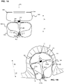
- FIGS 1A and 1B are illustrations of a profile of an example implant 100 that can have a predetermined shape as illustrated in Figure 1 and an implanted shape as illustrated in Figure 1B .
- the implant 100 can include a distal braided segment 140 and a proximal braided segment 120, where a distal direction 24 and a proximal direction 22 are defined in relation to a physician administering the treatment.
- the braided segments 120, 140 can each be separate braids that are joined by a band 130 or can be a contiguous braid constricted by the band 130.
- the braided segments 120, 140 can be joined or constructed by an adhesive, suture, or other suitable material or component.
- the band 130 preferably includes radiopaque material.
- the radiopaque material can allow the band 130 to function as fluoroscopic marker that can be visualized during implantation as an indication of the position of the implant 100.
- the distal braided segment 140 can have an open end 114.
- the proximal braided segment 120 can have a pinched end 112 attached to a detachment feature 150.
- the detachment feature 150 is illustrated as a flat key that can be used with a mechanical implant delivery system (not illustrated).
- the braided segments 120, 140 can include memory shape material that can be heat set to the predetermined shape, can be deformed for delivery through a catheter ( Figure 2A ), and can self-expand to the implanted shape ( Figure 1B ) that is based on the predetermined shape and confined by the anatomy of an aneurysm 10 in which it is implanted.
- Figure 1A illustrates the predetermined shape of the implant 100 in which the distal braided segment 140 extends in a distal direction 24 from the band 130 forming a bowl shape and the proximal braided segment 120 extends in the proximal direction 22 from the band 130 and includes two inversions 122, 124 separating three sections 142, 144, 148 which at least partially overlap each other.
- the pinched end 112 is affixed to an innermost section 148 of the three sections.
- the band 130 is affixed to an outermost section 142 of the three sections.
- a middle section 144 of the three sections extends between the two inversions 122, 124 and is positioned within outermost section 142 and around the innermost section 148.
- the entirety of the distal braided segment is positioned in the distal direction 24 from the entirety of the proximal braided segment 120.
- the band 130 and the pinched end 112 can be approximately aligned along a longitudinal axis (L-L).
- the distal braided segment 140 and the proximal braided segment 120 can be respectively approximately radially symmetrical with respect to the longitudinal axis (L-L).
- Figure 1B illustrates the distal braided segment 140 functioning as a dome feature pressing into walls 14 of the aneurysm 10 near a dome 15 or distal portion of the aneurysm walls 14.
- Figure 1B illustrates the proximal braided segment 120 extending across a neck 16 of the aneurysm 10 and anchoring to aneurysm's walls 14 at least in a proximal portion of the aneurysm sac 12.
- the implant 100 provides sufficient coverage across the aneurysm neck 16 to induce venous stasis in the aneurysm sac 12 and provides a low density of embolic material within the aneurysm sac 12 so that a majority of thrombotic mass within the aneurysm 10 following treatment is naturally formed.
- the distal braided segment 140 provides a force (F) in the proximal direction 22 to inhibit the proximal braided segment 120 from moving distally into the aneurysm sac 12.
- the proximal braided segment 120 can have an outer layer 142a contacting the aneurysm's wall 14, a sack 144a nested within the outer layer 142a, a proximal inversion 122a positioned at the aneurysm's neck 16, and a distal inversion 124a positioned near the band 130.
- An inner layer 148a of the proximal braided segment 120 can form a compaction resistant column extending from approximate the band 130 to approximate the aneurysm's neck 16 through the sack 144a.
- the proximal braided segment 120 can be constricted radially when implanted so that the outer layer 142a presses into the aneurysm walls 14 as it moves toward the predetermined shape ( Figure 1A ) and is inhibited from attaining the predetermined shape due to confinement within the aneurysm 10. Further, the sack 144a can press into the outer layer 142a to facilitate anchoring of the proximal braided segment 120.
- the outer layer 142a of the proximal braided segment 120 in the implanted shape can correspond to the outer layer 142 in the predetermined shape
- the proximal inversion 122a in the implanted shape can correspond to the inversion 122 adjacent to the outer layer 142 in the predetermined shape
- the sack 144a in the implanted shape can correspond to the middle section 144 in the predetermined shape
- the distal inversion 124a in the implanted shape can correspond to the inversion 124 adjacent to the innermost section 148 in the predetermined shape
- the inner layer 148a in the implanted shape can correspond to the innermost section 148 in the predetermined shape.
- the sack 144a can have a neck opening 126a corresponding to a neck opening 126 in the predetermined shape.
- the neck opening 126a is constricted around the inner layer 148a to inhibit blood from entering the sack 144a.
- Figures 2A through 2G are a sequence of illustrations depicting an example aneurysm treatment.
- Figure 2A illustrates the implant 100 positioned within a catheter 60.
- the implant 100 is collapsed for delivery through vasculature.
- the braided segments 120, 140 can be tubular.
- tubular and “tube” are to be construed broadly and are not limited to a structure that is a right cylinder or strictly circumferential in cross-section or of a uniform cross-section throughout its length.
- a tubular structure can have a tapered or curved outer surface without departing from the scope of the present invention.
- each of the braided segments 120, 140 are extended in respective tubular shapes respectively having a single layer of braid.
- the distal braided segment 140 preferably has a length L1 that is less than the length L2 of the proximal braided segment 120 when each are respectively collapsed to single layer tubular shapes having approximately equal diameter as illustrated in Figure 2A .
- a delivery system can be attached to the detachment feature 150 to move the implant 100 through the catheter 60.
- the implant 100 can be manipulated at the pinched end and the catheter 60 can be manipulated to move the implant 100 through the sequence of treatment steps illustrated in Figures 2B through 2G .
- Figure 2B illustrates the distal braided segment 140 being pushed from the catheter 60 into the sac 12 of the aneurysm 10.
- the distal braided segment 140 expands toward the bowl shape of the predetermined shape illustrated in Figure 1A and is inhibited from moving completely to the bowl shape by contacting walls 14 of the aneurysm 10.
- Figure 2C illustrates the distal braided segment 140 pressed into the dome 15 of the aneurysm wall 14, the band 130 being positioned in the aneurysm sac 12, and the proximal braided segment 120 beginning to be expelled from the catheter 60.
- the band 130 includes radiopaque material
- the band 130 can be visualized within the aneurysm sac 12 to confirm that the distal braided segment 140 is completely expelled from the catheter 60.
- a portion of the proximal braided segment 120 corresponding to the outer layer 142 in the predetermined shape is illustrated as expanding outwardly to move toward the predetermined shape of the outer layer 142.
- the expelled portion of the proximal braided segment 120 is inhibited from moving completely to the predetermined shape as it comes into contact with aneurysm walls 14 and neck opening 16.
- Figure 2D illustrates the distal braided segment 140 pressed further into the dome 15 and additional braid from the proximal braided segment 120 being expelled from the catheter 60.
- Figure 2E illustrates the proximal braided segment 120 expanding to conform to the aneurysm walls 14 and neck opening 16 as the proximal braided segment 120 is further expelled from the catheter 60.
- Figure 2F illustrates the proximal braided segment 120 beginning to invert near the neck opening 16 as the proximal braided segment 120 is further expelled from the catheter 60.
- Figure 2G illustrates the proximal braided segment 120 fully expelled so that the implant 100 is in an implanted shape similar to as illustrated in Figure 1B .
- the detachment feature 150 can be disengaged and the catheter 60 can be retracted to leave the implant 100 implanted as illustrated in Figure 1B .
- Figure 3A is an illustration of another example implant 200 in a predetermined shape.
- Figures 3B and 3C are illustrations of the example implant 200 in two stable implanted shapes.
- the implant 200 can treat a range of aneurysm sizes including a larger aneurysm 10a as illustrated in Figure 3B and a smaller aneurysm 10b as illustrated in Figure 3C .
- the implant 200 can have a first implanted shape ( Figure 3B ) that can be conducive for treating larger aneurysms 10a and a second implanted shape ( Figure 3C ) that can be conducive for treating smaller aneurysms 10b.
- the implant 200 can include a distal braided segment 240 having an open end 214 and a predetermined shape similar to that of the distal braided segment 140 of the implant 100 illustrated in Figure 1A .
- the implant 200 can include a proximal braided segment 220 having a pinched end 212 and two inversions 222, 224 similar to corresponding features 112, 122, 124 of the proximal braided segment 120 of the implant 100 illustrated in Figure 1A .
- the proximal braided segment 220 can have an outermost section 242 affixed to the band 130, a middle section 244 extending between the two inversions 222, 224, and an innermost section 246 surrounded by the middle section 244 and affixed to the detachment feature 150 at the pinched end 212.
- the middle section 244 of the implant 200 illustrated in Figure 3A can further include one or more bends 232, 234 to facilitate movement of the implant 200 into the implanted shape illustrated in Figure 3C .
- the innermost section 246 of the implant 200 illustrated in Figure 3A can be truncated so that the pinched end 112 (and thereby the detachment feature 150) is suspended within a sack formed by the middle section 244 when the implant 200 is in the predetermined shape.
- Figure 3B illustrates the implant 200 in a first implanted shape in the larger aneurysm 10a having a substantially spherical cavity that is larger than a substantially spherical cavity of the smaller aneurysm 10b illustrated in Figure 3C .
- the open end 214 is positioned approximate a distal wall, dome 15a of the larger aneurysm 10a, the band 130 is suspended within a sac 12a of the larger aneurysm 10a, and the proximal braided segment 220 has two inversions 222a, 224a separating three sections 242a, 244a, 246a which at least partially overlap each other.
- the two inversions 222a, 224a and the three sections 242a, 244a, 246a of the proximal braided segment 220 when the implant is in the first implanted shape correspond approximately to the two inversions 222, 224 and the three sections 242, 244, 246 of the proximal braided segment 220 when the implant 200 is in the predetermined shape as illustrated in Figure 3A .
- the proximal braided segment 220 is anchored into the aneurysm walls 14a at least in part by a force F in the proximal direction 22 from the distal braided segment 240 so that the proximal braided segment 220 remains in place across the aneurysm neck 16a.
- the sack 244a can have a neck opening 226a corresponding to a neck opening 226 in the predetermined shape.
- the first implanted shape of the implant 200 illustrated in Figure 3B can be similar to that of the implanted shape of the implant 100 illustrated in Figure 1B with an exception that the inner layer 246a of the implant 200 illustrated in Figure 3B is foreshortened compared to the inner layer 148a of the implant 100 illustrated in Figure 1B .
- the implant 200 can be implanted in the larger aneurysm 10a as illustrated in Figure 3B following steps similar to those illustrated in Figures 2A through 2G .
- Figure 3C illustrates the implant 200 in a second implanted shape in the smaller spherical cavity of the smaller aneurysm 10b.
- the open end 214 is positioned approximate a distal wall, dome 15b of the smaller aneurysm 10b, the band 130 is suspended within the smaller aneurysm 10b, and the second braided segment 220 has two inversions 222b, 224b separating three sections 242b, 244b, 246b which at least partially overlap each other.
- One of the two inversions 224b when the implant is in the second implanted shape, corresponds to a bend 232 in the middle section 244 when the implant 200 is in the predetermined shape illustrated in Figure 3A .
- the proximal braided segment 220 is anchored into the aneurysm walls 14b at least in part by a force F in the proximal direction 22 from the distal braided segment 240 so that the proximal braided segment 220 remains in place across the aneurysm neck 16b.
- the proximal braided segment 220 can be radially constricted so that an outer layer 242b presses into the aneurysm wall 14.
- a middle layer 244b can press into the outer layer 242b to further anchor the proximal braided segment 220.
- An inner layer 246b can press into the middle layer 244b to further anchor the proximal braided segment 220.
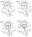
- Figures 4A through 4D are a sequence of illustrations depicting an example aneurysm treatment where the implant 100 is implanted in the second implanted shape illustrated in Figure 3C .
- the treatment sequence can begin following steps similar to as illustrated in Figures 2A through 2C .
- implants 100, 200 illustrated in Figures 1A and 3A have similar dimensions
- the second implanted shape of the implant 200 illustrated in Figure 3C allows that implant 200 to be implanted in a smaller aneurysm 10b compared to the aneurysm 10 illustrated in Figures 2B through 2G .
- the distal braided segment 240 of the implant 200 illustrated in Figures 4A through 4D therefore may occupy a greater percentage of the volume of the smaller aneurysm sac 12b compared to the treatment illustrated in Figures 2A through 2G .
- Figure 4A illustrates the distal braided segment 240 pressed into the dome 15b and braid from the proximal braided segment 220 being expelled from the catheter 60.
- Figure 4B illustrates the proximal braided segment 220 expanding to conform to the aneurysm walls 14b and neck opening 16b as the proximal braided segment 220 is further expelled from the catheter 60.
- Figure 4C illustrates the proximal braided segment 220 inverted to a shape similar to that of the first implanted shape illustrated in Figure 3B .
- the proximal braided segment 220 extends into the vasculature, impeding flow from a stem blood vessel 20 to branch blood vessels 22a, 22b. While it may be possible to leave the proximal braided segment 220 stabilized in this shape when implanted, it may not be desirable to do so.
- Figure 4D illustrates the proximal braided segment 220 collapsed to the second implanted shape similar to that illustrated in Figure 3C .
- Movement of the proximal braided segment 220 into the second implanted shape can be accomplished via manipulation of the catheter 60 and the pinched end 212.
- Bends 232, 234 in the middle section 244 of the proximal braided section 220 in the predetermined shape can promote movement of the proximal braided section 220 from the shape illustrated in Figure 4C to the second implanted shape illustrated in Figure 4D .
- the detachment feature 150 can be disengaged and the catheter 60 can be retracted to leave the implant 200 implanted as illustrated in Figure 3C .
- Figure 5A is an illustration of dimensions of an example implant in a predetermined shape.
- the proximal braided segment 120 has a height (H1) and a diameter (D1).
- the distal braided segment 140 has a height (H2) and a diameter (D2).
- the open end 114 of the distal braided segment 140 has a diameter (D3) about equal to that of the diameter (D2) of the distal braided segment 140.
- the implant 100 has a height H3 that is at least the sum of the height (H1) of the proximal braided segment 120 and the height (H2) of the distal braided segment 140.
- Predetermined shapes of other example implants illustrated and described herein, and variations thereof can have similar dimensions.
- Figure 5B is an illustration of height (HA), sac diameter (DA), and neck diameter (DN) measurements of an aneurysm 10.
- the location of the plane 18 defining a boundary between the aneurysm 10 and blood vessels is also illustrated.
- the diameter (D1) of the proximal braided segment 120 and the diameter (D2) of the distal braided segment 140 to be about equal to, or slightly greater than the sac diameter (DA) so that the distal braided segment 140 and proximal braided segment 120 press radially into the aneurysm walls 14.
- Figure 5C is an illustration of dimensions of an example implant in an implanted shape.
- the proximal braided segment 120 has a height (H1') and a diameter (D1').
- the diameter (D1') of the proximal braided segment 120 in the implanted shape can be collapsed compared to the diameter (D1) of the proximal braided segment 120 in the predetermined shape.
- the distal braided segment 140 has a height (H2') and a diameter (D2').
- a diameter (D3') of the open end 114 of the distal braided segment 140 in the implanted shape can be collapsed relative to the diameter (D3) of the open end 114 distal braided segment 140 in the predetermined shape.
- the implant 100 has a height (H3') that is at least the sum of the height (H1') of the proximal braided segment 120 and the height (H2') of the distal braided segment 140.
- the height (H3') of the implant 100 can be elongated or collapsed compared to the height (H3) of the implant when in the predetermined shape.
- Radial constriction of the diameter (D1') of the proximal section 120 can cause elongation of height (H1') of the proximal section, while collapse of the diameter (D3') of the open end 114 and longitudinal compression of the distal braided section 140 can cause foreshortening of the height (H2') of the distal braided section 140 and reduction or elimination of any gap between the distal and proximal braided sections 120, 140.
- Implanted shapes of other example implants illustrated and described herein, and variations thereof can have similar dimensions.
- Figure 6A is an illustration of an example implant 300 in another alternative predetermined shape.
- Figure 6B is an illustration of the example implant 300 in an implanted shape.
- the implant 300 includes a distal braided segment 340 and a proximal braided segment 320.
- the distal braided segment 340 can have an open end 314 and be shaped and implanted similarly to the distal braided segments 140, 240 in previous figures.
- the proximal braided segment 320 can have a pinched end 312 with a detachment feature 150 attached thereto.
- the implant 300 can be formed in the predetermined shape, collapsed for delivery through a microcatheter, attached to a delivery system at the detachment feature 150, and implanted in the implanted shape.
- Figure 6A illustrates proximal braided segment 320 having two inversions 322, 324, dividing the proximal braided segment 320 into three segments 342, 344, 346 in the predetermined shape.
- the proximal braided segment 320 can have an outermost section 342 extending from the band 130 to one of the inversions 322, an innermost section 346 extending from the pinched end 312 to the other of the inversions 324, and a middle section 344 extending between the two inversions 322, 324.
- the proximal braided segment 320 and distal braided segment 340 can each be substantially radially symmetrical about a central vertical axis.
- the outermost sections 142, 242, 342 are respectively similar to each other; the innermost section 346 of the implant 300 illustrated in Figure 6A can be elongated, foreshortened, or any length between the innermost sections 148, 246 of the previously illustrated implants 100, 200; and the middle section 344 of the proximal braided segment 320 illustrated in Figure 6A has an undulating pattern rather than the "S" shape of the middle section 144, 244 of previously illustrated implants 100, 200.
- the undulating middle section 344 can be radially symmetrical to form a honeycomb shape.
- the middle section 344 in the undulating pattern can provide a force pattern pressing outwardly to anchor the implant 300 within an aneurysm that is different from a force pattern that could be provided by the middle sections 144, 244 having the "S" shape.
- the pinched end 312 of the braid 310 in Figure 6A can be positioned near the inversion 324 adjacent the inner segment 346 as illustrated.
- the inner segment 346 can be shaped to extend to the inversion 322 adjacent the outer section 342 to provide a compaction resistant column.
- Figure 6B illustrates the proximal braided segment 320 having an outer layer 342a shaped to contact an aneurysm wall, compressed extensions of an undulating middle layer 344a nested within the outer layer 342a, a proximal inversion 322a positioned to be placed an aneurysm neck, and a distal inversion 324a positioned to be placed near the band 130.
- the detachment feature 150 and pinched end 312 of the proximal braided segment 320 can be positioned within the aneurysm sac, extending from an innermost layer 346a of proximal braided segment 320, either near the distal inversion 324a as illustrated, near the proximal inversion 322a, or at a position in between.
- the detachment feature 150 and pinched end 312 can be positioned to reduce the likelihood that the implant 300 becomes impacted.
- the distal braided segment 340 can provide a force F in the proximal direction 22 against the proximal braided segment 320 to anchor the implant 300 within an aneurysm or spherical cavity.
- the outer layer 342a and middle layer 344a can provide a radially outward force to anchor the implant 30 within an aneurysm or spherical cavity.
- Figure 7A is an illustration of an example implant 400 in another alternative predetermined shape.
- Figure 7B is an illustration of the example implant 400 in an implanted shape.
- the implant 400 has a distal braided segment 440 having an open end 414 and a proximal braided segment 420 having a pinched end 412.
- a detachment feature 150 can be attached to the proximal braided segment 420 at the pinched end 412.
- the implant 400 can be formed in the predetermined shape, collapsed for delivery through a microcatheter, attached to a delivery system at the detachment feature 150, and implanted in the implanted shape.
- Figure 7A illustrates the proximal braided segment 420 having two inversions 422, 424, dividing the proximal braided segment 420 into three sections 442, 444, 446.
- the proximal braided segment 420 can have an outermost section 442 extending from the band 130 to one of the inversions 422, an innermost section 446 extending from the pinched end 412 to the other of the inversions 424, and a middle section 444 extending between the two inversions 422, 424.
- the proximal braided segment 420 can be substantially radially symmetrical about a central vertical axis (L-L).
- the distal braided segment 440 can be shaped and implanted similar to the distal braided segment 140, 240, 340 of previously illustrated implants 100, 200, 300.
- the outermost sections 142, 242, 442 can be similar to each other, the middle section 444 of the proximal braided segment 420 illustrated in Figure 7A can have a less pronounced "S" shape compared to the "S" shaped middle section 144, 244 illustrated in Figures 1A and 3A , and the innermost section 446 can be conical or "V" shaped in profile with the pinched end 412 positioned near the proximal inversion 422. When implanted, the innermost section 446 can reshape to form a compaction resistant column.
- Figure 7B illustrates the proximal braided segment 420 in an implanted shape having an outer layer 442a shaped to contact an aneurysm wall, a tulip or heart shaped sack 444a nested within the outer layer 442a, a proximal inversion 422a positioned to be placed at an aneurysm neck, a distal inversion 424a positioned to be placed near the band 130, and a compaction resistant column 446a extending within the sack 444a.
- the detachment feature 150 and pinched end 412 can be positioned within the sack 444a near the proximal inversion 422a.
- the detachment feature 150 and pinched end 412 can be positioned to reduce the likelihood that the implant 400 becomes impacted.
- the distal braided segment 440 can provide a force F in the proximal direction 22 against the proximal braided segment 420 to anchor the implant 400 within an aneurysm or spherical cavity.
- the outer layer 442a and middle layer 444a can provide a radial force to anchor the implant 400 within an aneurysm or spherical cavity.
- Figure 8 is an illustration of a braid having closed looped ends 30.
- the braid can be positioned so that the closed looped ends 30 correspond to the open end 114, 214, 314, 414 of any of the previously illustrated implants 100, 200, 300, 400.
- FIG 9 is an illustration of another aneurysm treatment.
- embolic coils 32 can be implanted prior to the implant 100.
- the embolic coils 32 can be implanted by known methods. Any of the previously illustrated implants 100, 200, 300, 400 can be subsequently implanted following steps illustrated and described herein and variations thereof.
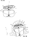
- FIGs 10A and 10B are illustrations of another example implant 500 in a predetermined shape ( Figure 10A ) and an implanted shape ( Figure 10B ).
- the implant 500 includes an embolic coil 552 formed in a spiraling predetermined shape.
- the embolic coil 552 can function as a dome feature configured to press into aneurysm walls near the aneurysm's dome, distal portion of the aneurysm sac.
- FIGs 11A and 11B are illustrations of another example implant in a predetermined shape ( Figure 11A ) and an implanted shape ( Figure 11B ).
- the implant 600 includes a wire frame 654 configured to anchor in an aneurysm dome, thereby functioning as a dome feature.
- the implants 500, 600 respectively illustrated in Figures 10A, 10B , 11A, and 11B can respectively further include a proximal braided segment 520, 620 configured to extend across the aneurysm neck and anchor to the aneurysm's walls at least in the proximal portion of the aneurysm sac 12.
- Each of the proximal braided segments 520, 620 can be respectively joined to the embolic coil 552 or wire frame 654 by the band 130.
- Any of the previously illustrated proximal braided segments 120, 220, 320, 420 and variations thereof can be used in place of either of the proximal braided segments 520, 620 illustrated in Figures 10A through 11B .
- the embolic coil 552 or the wire frame 654 can be elongated within a microcatheter and expelled from the microcatheter into an aneurysm or cavity.
- the respective proximal braided segment 520, 620 can subsequently be expelled from the catheter and implanted as described elsewhere herein.
- the terms “about” or “approximately” for any numerical values or ranges indicate a suitable dimensional tolerance that allows the part or collection of components to function for its intended purpose as described herein. More specifically, “about” or “approximately” may refer to the range of values ⁇ 20% of the recited value, e.g. "about 90%” may refer to the range of values from 71% to 99%.
Landscapes
- Health & Medical Sciences (AREA)
- Surgery (AREA)
- Life Sciences & Earth Sciences (AREA)
- Veterinary Medicine (AREA)
- Heart & Thoracic Surgery (AREA)
- Vascular Medicine (AREA)
- Public Health (AREA)
- General Health & Medical Sciences (AREA)
- Animal Behavior & Ethology (AREA)
- Biomedical Technology (AREA)
- Medical Informatics (AREA)
- Molecular Biology (AREA)
- Nuclear Medicine, Radiotherapy & Molecular Imaging (AREA)
- Engineering & Computer Science (AREA)
- Reproductive Health (AREA)
- Neurosurgery (AREA)
- Physics & Mathematics (AREA)
- Optics & Photonics (AREA)
- Epidemiology (AREA)
- Surgical Instruments (AREA)
- Prostheses (AREA)
Abstract
Description
- The present application claims the benefit of priority under 35 USC §119 of
U.S. Provisional Patent Application No. 63/082,013, filed on September 23, 2020 - The present invention generally relates to medical instruments, and more particularly, to embolic implants for aneurysm therapy.
- Cranial aneurysms can be complicated and difficult to treat due to their proximity to critical brain tissues. Current treatments can involve intravascularly delivering embolic coils that fill the sac of the aneurysm or block the entrance or neck of the aneurysm to prevent blood flow into the aneurysm. When filling an aneurysm sac, the embolic coils clots the blood, creating a thrombotic mass within the aneurysm. When treating the aneurysm neck, blood flow into the entrance of the aneurysm is inhibited, inducing venous stasis in the aneurysm and facilitating a natural formation of a thrombotic mass within the aneurysm. Naturally formed thrombotic masses can result in improved healing compared to aneurysm masses packed with embolic material because naturally formed thrombotic masses can reduce the likelihood of distention from arterial walls and facilitate reintegration into the original parent vessel shape along the neck plane. However, properly placing embolic coils across the aneurysm neck can be challenging. Embolic coils delivered to the neck of the aneurysm can potentially have the adverse effect of impeding the flow of blood in the adjoining blood vessel, particularly if the entrance is overpacked. Conversely, if the entrance is insufficiently packed, blood flow can persist into the aneurysm. Whether treating the aneurysm neck or packing the aneurysm with coils, treating certain aneurysm morphology (e.g. wide neck, bifurcation, etc.) can require ancillary devices such a stents or balloons to support the coil mass and obtain the desired packing density. Once implanted, the coils cannot easily be retracted or repositioned. Furthermore, embolic coils do not always effectively treat aneurysms as aneurysms treated with multiple coils often recanalize or compact because of poor coiling, lack of coverage across the aneurysm neck, blood flow, or large aneurysm size.
- Tubular braided implants have the potential to easily, accurately, and safely treat an aneurysm or other arterio-venous malformation in a parent vessel without blocking flow into perforator vessels communicating with the parent vessel. A tubular braided implant that can be used in addition to, or as an alternative to embolic coil treatments of aneurysms is disclosed in
U.S. Pat. No. 10,653,425 - Example implants presented herein can be implanted in an aneurysm to cause thrombogenesis within the aneurysm's sac. Example implants include a braid that can extend across the aneurysm neck and anchor to aneurysm's walls at least in the proximal portion of the aneurysm sac. Example implants can further include a dome feature configured to press into aneurysm walls near the aneurysm's dome at a distal portion of the aneurysm sac. The braid at the aneurysm's neck and the dome feature can be joined or constricted at a junction. The dome feature can facilitate proper anchoring of the braid across the aneurysm's neck. Various examples of implants having variations in dome features and variations in braided portions are presented herein. The dome features and braided portions are interchangeable between examples.
- An example implant can include a first braided segment, a second braided segment, and a band. The example implant can be shaped to have a predetermined shape. The first braided segment can include a distal open end. The second braided segment can include a proximal pinched end. The band can be positioned at a junction between the first braided segment and the second braided segment. The band can constrict the first braided segment and the second braided segment at the junction. The first braided segment can function as a dome feature and the second braided segment can be positioned across an aneurysm neck.
- In the predetermined shape, the first braided segment can extend in a distal direction from the band and form a bowl shape. In the predetermined shape, the second braided segment can extend in a proximal direction from the band. In the predetermined shape, the second braided segment can include two inversions separating three sections which at least partially overlap each other such that the pinched end is affixed to an innermost section of the three sections, the band is affixed to an outermost section of the three sections, and a middle section of the three sections extends between the two inversions and is positioned within outermost section and around the innermost section.
- In the predetermined shape, the entirety of the first braided segment of the implant can be positioned in the distal direction from the entirety of the second braided segment of the implant.
- In the predetermined shape, the band and the pinched end can be approximately aligned along a longitudinal axis. The first braided segment and the second braided segment can be respectively approximately radially symmetrical with respect to the longitudinal axis.
- The implant can be collapsible to a dimension sized to traverse a microcatheter within neurovasculature.
- The implant can be configured to be manipulated at the pinched end to position the implant in an implanted shape in a spherical cavity. The implanted shape can be based in part on the predetermined shape and based in part on the geometry of the spherical cavity.
- In the implanted shape, the first braided section can provide a force pressing the second braided section in the proximal direction due to compression of the first braided section against a dome of the spherical cavity.
- In the implanted shape, the open end can be positioned approximate a distal wall of the spherical cavity, the band can be suspended within the spherical cavity, and the second braided segment can include two inversions separating three sections which at least partially overlap each other.
- The two inversions and the three sections of the second braided segment when the implant is in the implanted shape can correspond approximately to the two inversions and the three sections of the second braided segment when the implant is in the predetermined shape.
- In the implanted shape, a diameter of the open end is collapsed in comparison to the diameter of the open end when the implant is in the predetermined shape. In the implanted shape, a height of the first segment is foreshortened in comparison to the height of the first segment when the implant is in the predetermined shape.
- The open end can include closed looped braid strands.
- The band can include radiopaque material.
- The implant can be stable in two different implanted shapes, where the stable shape that the implant takes can be selected during treatment to fit within a smaller or larger spherical cavity. The implant can be stable in a first implanted shape based on the predetermined shape when constrained by a first substantially spherical cavity. The implant can be stable in a second implanted shape based on the predetermined shape when constrained by a second substantially spherical cavity smaller than the first substantially spherical cavity,
- In the first implanted shape, the open end is positioned approximate a distal wall of the first substantially spherical cavity, the band is suspended within the first substantially spherical cavity, and the second braided segment includes two inversions separating three sections which at least partially overlap each other. The two inversions and the three sections of the second braided segment when the implant is in the first implanted shape correspond approximately to the two inversions and the three sections of the second braided segment when the implant is in the predetermined shape.
- In the second implanted shape, the open end is positioned approximate a distal wall of the second substantially spherical cavity, the band is suspended within the second substantially spherical cavity, and the second braided segment includes two inversions separating three sections which at least partially overlap each other. One of the two inversions, when the implant is in the second implanted shape, corresponds to a bend in the middle section when the implant is in the predetermined shape.
- An example method for constructing an implant can include one or more of the following steps presented in no particular order, and the method can include additional steps not included here. A band can be affixed between a first braided segment and a second braided segment, the first braided segment including a distal open end and the second braided segment including a proximal pinched end. The implant can be shaped to a predetermined shape to which the implant is capable of self-expanding. Shaping the implant to the predetermined shape can include: forming the first braided segment to a bowl shape extending in a distal direction from the band; inverting the second braided segment to form a proximal inversion folded toward the distal direction thereby defining an outermost section of the second braided segment; and inverting the second braided segment to form a distal inversion folded toward the proximal direction thereby defining a middle section between the proximal and distal inversions of the second braided segment that is at least partially surrounded by the outermost section and defining an innermost section between the distal inversion and the pinched end that is at least partially surrounded by the middle section.
- The method can further include shaping the implant to the predetermined shape such that when the implant is in the predetermined shape, the entirety of the first braided segment is positioned in the distal direction from the entirety of the second braided segment.
- The method can further include shaping the implant to the predetermined shape such that when the implant is in the predetermined shape, the band and the pinched end are approximately aligned along a longitudinal axis and the first braided segment and the second braided segment are respectively approximately radially symmetrical with respect to the longitudinal axis.
- The method can further include collapsing the implant and positioning the implant in a microcatheter sized to traverse neurovasculature.
- The method can further include affixing a delivery system to the implant approximate the pinched end so that the pinched end can be manipulated to move the implant from a distal end of the microcatheter.
- The method can further include forming a bend in the middle section of the second braided segment that is configured to fold to form an inversion when the implant is positioned, via manipulation of the pinched end, in a substantially spherical cavity.
- An example method of treating an aneurysm can include one or more of the following steps presented in no particular order, and the method can include additional steps not included here. An open end of a first braided segment of an implant can be pushed from a distal end of a microcatheter into a sac of an aneurysm. The first braided segment can be shaped to form a distal sack positioned against a dome of the aneurysm and extending centrally through the sac to a band affixed to the first braided segment. An outer section of a second braided segment of the implant can be shaped to form proximal sack extending centrally through the sac from the band, positioned against a portion of the aneurysm wall in a proximal direction from the distal sack, and extending across at least a portion of a neck opening of the aneurysm. The second braided segment can be inverted approximate the neck opening of the aneurysm. The second braided segment can be inverted within the proximal sack.
- The method can further include pressing the distal sack into the dome.
- The method can further include implanting embolic coils near a distal wall of the aneurysm.
- The method can further include pressing the distal sack into the embolic coils.
- The method can further include releasing the implant in an implanted configuration such that the first braided segment provides a force to press the second braided segment in the proximal direction.
- The implant can have a predetermined shape in which the second braided segment includes two inversions separating three sections which at least partially overlap each other such that the pinched end is affixed to an innermost section of the three sections, the band is affixed to an outermost section of the three sections which forms the proximal sack, a middle section of the three sections extends between the two inversions, the middle section is positioned within outermost section and around the innermost section, and the middle section includes a bend. The step of inverting the second braided segment within the proximal sack can include folding the middle section at the bend such that the bend forms an inversion of the second braided segment within the proximal sack.
- Another example implant can include an embolic coil, a braided segment, and a band positioned at a junction between the embolic coil and braided segment. The implant can have a predetermined shape in which the embolic coil extends in a distal direction from the band forming a spiral shape and the braided segment extends in a proximal direction from the band and comprises two inversions separating three sections. The three section can at least partially overlap each other. The braided segment can have a pinched end that is affixed to an innermost section of the three sections. The band can be affixed to an outermost section of the three sections. A middle section of the three sections can extend between the two inversions and can be positioned within the outermost section and around the innermost section. The braided segment can otherwise be configured similarly to the second braided segment or proximal braided segment of any example braided implant described herein.
- Another example method for constructing an implant can include one or more of the following steps presented in no particular order, and the method can include additional steps not included here. A band can be affixed at a junction between an embolic coil and a distal end of a braided segment. The implant can be shaped to a predetermined shape to which the implant is capable of self-expanding. The shaping can include forming the embolic coil to a spiral shape extending in a distal direction from the band; inverting the braided segment to form a proximal inversion folded toward the distal direction thereby defining an outermost section of the second braided segment; and inverting the braided segment to form a distal inversion folded toward the proximal direction thereby defining a middle section between the proximal and distal inversion of the second braided segment that is at least partially surrounded by the outermost section and defining an innermost section between the distal inversion and the pinched end that is at least partially surrounded by the middle section. The example method can further include any of the steps for shaping the braided segment as described in any other example method for constructing an implant presented herein as such methods relate to shaping a second braided segment or a proximal braided segment.
- Another method of treating an aneurysm can include one or more of the following steps presented in no particular order, and the method can include additional steps not included here. An embolic coil of an implant can be pushed from a distal end of a microcatheter into a sac of an aneurysm. The embolic coil can be positioned against a distal wall of the aneurysm. A band joining the embolic coil to the braided segment can be positioned within the aneurysm sac. The braided segment can be shaped to include two inversions. The braided segment can be released from a delivery system such that the braided segment remains anchored within the aneurysm sac. The example method can further include any of the steps for implanting the braided segment as described in any other example method of treatment presented herein as such methods relate to implanting a second braided segment or a proximal braided segment.
- Another example implant can include a wire frame, a braided segment, and a band positioned at a junction between the wire frame and the braided segment. The implant can have a predetermined shape in which the wire frame extends in a distal direction from the band forming a spiral shape and the braided segment extends in a proximal direction from the band and includes two inversions separating three sections which at least partially overlap each other. A pinched end of the braided segment can be is affixed to an innermost section of the three sections. The band can be affixed to an outermost section of the three sections. A middle section of the three sections can extend between the two inversions and can be positioned within the outermost section and around the innermost section. The braided segment can otherwise be configured similarly to the second braided segment or proximal braided segment of any example braided implant described herein.
- Another example method for constructing an implant can include one or more of the following steps presented in no particular order, and the method can include additional steps not included here. A band can be affixed at a junction between a wire frame and a distal end of a braided segment. The implant can be shaped to a predetermined shape to which the implant can be capable of self-expanding. The shaping can include forming the wire frame to a spiral shape extending in a distal direction from the band; inverting the braided segment to form a proximal inversion folded toward the distal direction thereby defining an outermost section of the second braided segment; and inverting the braided segment to form a distal inversion folded toward the proximal direction thereby defining a middle section between the proximal and distal inversion of the second braided segment that is at least partially surrounded by the outermost section and defining an innermost section between the distal inversion and a pinched end of the braided segment that is at least partially surrounded by the middle section. The example method can further include any of the steps for shaping the braided segment as described in any other example method for constructing an implant presented herein as such methods relate to shaping a second braided segment or a proximal braided segment.
- Another method of treating an aneurysm can include one or more of the following steps presented in no particular order, and the method can include additional steps not included here. A wire frame of an implant can be pushed from a distal end of a microcatheter into a sac of an aneurysm. The wire frame can be positioned against a distal wall of the aneurysm. A band joining the wire frame to a braided segment of the implant can be positioned within the aneurysm sac. The braided segment can be shaped to include two inversions. The braided segment can be released from a delivery system such that the braided segment remains anchored within the aneurysm sac. The example method can further include any of the steps for implanting the braided segment as described in any other example method of treatment presented herein as such methods relate to implanting a second braided segment or a proximal braided segment.
- The above and further aspects of this invention are further discussed with reference to the following description in conjunction with the accompanying drawings, in which like numerals indicate like structural elements and features in various figures. The drawings are not necessarily to scale, emphasis instead being placed upon illustrating principles of the invention. The figures depict one or more implementations of the inventive devices, by way of example only, not by way of limitation.
-
Figure 1A is an illustration of an example implant in a predetermined shape according to aspects of the present invention. -
Figure 1B is an illustration of the example implant illustrated inFigure 1A in an implanted shape according to aspects of the present invention. -
Figures 2A through 2G are a sequence of illustrations depicting an example aneurysm treatment according to aspects of the present invention. -
Figure 3A is an illustration of another example implant in a predetermined shape according to aspects of the present invention. -
Figures 3B and 3C are illustrations of the example implant illustrated inFigure 3A in two stable implanted shapes according to aspects of the present invention. -
Figures 4A through 4D are a sequence of illustrations depicting another example aneurysm treatment according to aspects of the present invention. -
Figure 5A is an illustration of dimensions of an example implant in a predetermined shape according to aspects of the present invention. -
Figure 5B is an illustration of dimensions of an example aneurysm having a substantially spherical cavity. -
Figure 5C is an illustration of dimensions of an example implant in an implanted shape according to aspects of the present invention. -
Figures 6A and 6B are illustrations of another example implant in a predetermined shape (Figure 6A ) and an implanted shape (Figure 6B ) according to aspects of the present invention. -
Figures 7A and 7B are illustrations of another example implant in a predetermined shape (Figure 7A ) and an implanted shape (Figure 7B ) according to aspects of the present invention. -
Figure 8 is an illustration of a braid having closed looped ends according to aspects of the present invention. -
Figure 9 is an illustration of another aneurysm treatment according to aspects of the present invention. -
Figures 10A and 10B are illustrations of another example implant in a predetermined shape (Figure 10A ) and an implanted shape (Figure 10B ) according to aspects of the present invention. -
Figures 11A and 11B are illustrations of another example implant in a predetermined shape (Figure 11A ) and an implanted shape (Figure 11B ) according to aspects of the present invention. -
Figures 1A and 1B are illustrations of a profile of anexample implant 100 that can have a predetermined shape as illustrated inFigure 1 and an implanted shape as illustrated inFigure 1B . Theimplant 100 can include adistal braided segment 140 and aproximal braided segment 120, where adistal direction 24 and aproximal direction 22 are defined in relation to a physician administering the treatment. The braidedsegments band 130 or can be a contiguous braid constricted by theband 130. Alternatively, the braidedsegments - The
band 130 preferably includes radiopaque material. The radiopaque material can allow theband 130 to function as fluoroscopic marker that can be visualized during implantation as an indication of the position of theimplant 100. - The
distal braided segment 140 can have anopen end 114. Theproximal braided segment 120 can have apinched end 112 attached to adetachment feature 150. Thedetachment feature 150 is illustrated as a flat key that can be used with a mechanical implant delivery system (not illustrated). - The braided
segments Figure 2A ), and can self-expand to the implanted shape (Figure 1B ) that is based on the predetermined shape and confined by the anatomy of ananeurysm 10 in which it is implanted. -
Figure 1A illustrates the predetermined shape of theimplant 100 in which thedistal braided segment 140 extends in adistal direction 24 from theband 130 forming a bowl shape and theproximal braided segment 120 extends in theproximal direction 22 from theband 130 and includes twoinversions sections pinched end 112 is affixed to aninnermost section 148 of the three sections. Theband 130 is affixed to anoutermost section 142 of the three sections. Amiddle section 144 of the three sections extends between the twoinversions outermost section 142 and around theinnermost section 148. - In the illustrated predetermined shape, the entirety of the distal braided segment is positioned in the
distal direction 24 from the entirety of theproximal braided segment 120. In the predetermined shape, theband 130 and thepinched end 112 can be approximately aligned along a longitudinal axis (L-L). Thedistal braided segment 140 and theproximal braided segment 120 can be respectively approximately radially symmetrical with respect to the longitudinal axis (L-L). -
Figure 1B illustrates thedistal braided segment 140 functioning as a dome feature pressing intowalls 14 of theaneurysm 10 near adome 15 or distal portion of theaneurysm walls 14.Figure 1B illustrates theproximal braided segment 120 extending across aneck 16 of theaneurysm 10 and anchoring to aneurysm'swalls 14 at least in a proximal portion of theaneurysm sac 12. Implanted as such, theimplant 100 provides sufficient coverage across theaneurysm neck 16 to induce venous stasis in theaneurysm sac 12 and provides a low density of embolic material within theaneurysm sac 12 so that a majority of thrombotic mass within theaneurysm 10 following treatment is naturally formed. Thedistal braided segment 140 provides a force (F) in theproximal direction 22 to inhibit theproximal braided segment 120 from moving distally into theaneurysm sac 12. - In the implanted shape, the
proximal braided segment 120 can have anouter layer 142a contacting the aneurysm'swall 14, asack 144a nested within theouter layer 142a, aproximal inversion 122a positioned at the aneurysm'sneck 16, and adistal inversion 124a positioned near theband 130. Aninner layer 148a of theproximal braided segment 120 can form a compaction resistant column extending from approximate theband 130 to approximate the aneurysm'sneck 16 through thesack 144a. Theproximal braided segment 120 can be constricted radially when implanted so that theouter layer 142a presses into theaneurysm walls 14 as it moves toward the predetermined shape (Figure 1A ) and is inhibited from attaining the predetermined shape due to confinement within theaneurysm 10. Further, thesack 144a can press into theouter layer 142a to facilitate anchoring of theproximal braided segment 120. - The
outer layer 142a of theproximal braided segment 120 in the implanted shape can correspond to theouter layer 142 in the predetermined shape, theproximal inversion 122a in the implanted shape can correspond to theinversion 122 adjacent to theouter layer 142 in the predetermined shape, thesack 144a in the implanted shape can correspond to themiddle section 144 in the predetermined shape, thedistal inversion 124a in the implanted shape can correspond to theinversion 124 adjacent to theinnermost section 148 in the predetermined shape, and theinner layer 148a in the implanted shape can correspond to theinnermost section 148 in the predetermined shape. In the implanted shape, thesack 144a can have a neck opening 126a corresponding to aneck opening 126 in the predetermined shape. Preferably, the neck opening 126a is constricted around theinner layer 148a to inhibit blood from entering thesack 144a. -
Figures 2A through 2G are a sequence of illustrations depicting an example aneurysm treatment.Figure 2A illustrates theimplant 100 positioned within acatheter 60. Theimplant 100 is collapsed for delivery through vasculature. The braidedsegments segments distal braided segment 140 preferably has a length L1 that is less than the length L2 of theproximal braided segment 120 when each are respectively collapsed to single layer tubular shapes having approximately equal diameter as illustrated inFigure 2A . A delivery system can be attached to thedetachment feature 150 to move theimplant 100 through thecatheter 60. Theimplant 100 can be manipulated at the pinched end and thecatheter 60 can be manipulated to move theimplant 100 through the sequence of treatment steps illustrated inFigures 2B through 2G . -
Figure 2B illustrates thedistal braided segment 140 being pushed from thecatheter 60 into thesac 12 of theaneurysm 10. Thedistal braided segment 140 expands toward the bowl shape of the predetermined shape illustrated inFigure 1A and is inhibited from moving completely to the bowl shape by contactingwalls 14 of theaneurysm 10. -
Figure 2C illustrates thedistal braided segment 140 pressed into thedome 15 of theaneurysm wall 14, theband 130 being positioned in theaneurysm sac 12, and theproximal braided segment 120 beginning to be expelled from thecatheter 60. When theband 130 includes radiopaque material, theband 130 can be visualized within theaneurysm sac 12 to confirm that thedistal braided segment 140 is completely expelled from thecatheter 60. A portion of theproximal braided segment 120 corresponding to theouter layer 142 in the predetermined shape is illustrated as expanding outwardly to move toward the predetermined shape of theouter layer 142. The expelled portion of theproximal braided segment 120 is inhibited from moving completely to the predetermined shape as it comes into contact withaneurysm walls 14 andneck opening 16. -
Figure 2D illustrates thedistal braided segment 140 pressed further into thedome 15 and additional braid from theproximal braided segment 120 being expelled from thecatheter 60. -
Figure 2E illustrates theproximal braided segment 120 expanding to conform to theaneurysm walls 14 and neck opening 16 as theproximal braided segment 120 is further expelled from thecatheter 60. -
Figure 2F illustrates theproximal braided segment 120 beginning to invert near theneck opening 16 as theproximal braided segment 120 is further expelled from thecatheter 60. -
Figure 2G illustrates theproximal braided segment 120 fully expelled so that theimplant 100 is in an implanted shape similar to as illustrated inFigure 1B . Thedetachment feature 150 can be disengaged and thecatheter 60 can be retracted to leave theimplant 100 implanted as illustrated inFigure 1B . -
Figure 3A is an illustration of anotherexample implant 200 in a predetermined shape.Figures 3B and 3C are illustrations of theexample implant 200 in two stable implanted shapes. Theimplant 200 can treat a range of aneurysm sizes including alarger aneurysm 10a as illustrated inFigure 3B and asmaller aneurysm 10b as illustrated inFigure 3C . Theimplant 200 can have a first implanted shape (Figure 3B ) that can be conducive for treatinglarger aneurysms 10a and a second implanted shape (Figure 3C ) that can be conducive for treatingsmaller aneurysms 10b. Theimplant 200 can include adistal braided segment 240 having anopen end 214 and a predetermined shape similar to that of thedistal braided segment 140 of theimplant 100 illustrated inFigure 1A . Theimplant 200 can include aproximal braided segment 220 having apinched end 212 and twoinversions corresponding features proximal braided segment 120 of theimplant 100 illustrated inFigure 1A . Theproximal braided segment 220 can have anoutermost section 242 affixed to theband 130, amiddle section 244 extending between the twoinversions innermost section 246 surrounded by themiddle section 244 and affixed to thedetachment feature 150 at thepinched end 212. Compared to themiddle section 144 of theimplant 100 illustrated inFigure 1A , themiddle section 244 of theimplant 200 illustrated inFigure 3A can further include one ormore bends implant 200 into the implanted shape illustrated inFigure 3C . Compared to theinnermost section 148 of theimplant 100 illustrated inFigure 1A , theinnermost section 246 of theimplant 200 illustrated inFigure 3A can be truncated so that the pinched end 112 (and thereby the detachment feature 150) is suspended within a sack formed by themiddle section 244 when theimplant 200 is in the predetermined shape. -
Figure 3B illustrates theimplant 200 in a first implanted shape in thelarger aneurysm 10a having a substantially spherical cavity that is larger than a substantially spherical cavity of thesmaller aneurysm 10b illustrated inFigure 3C . In the first implanted shape illustrated inFigure 3B , theopen end 214 is positioned approximate a distal wall,dome 15a of thelarger aneurysm 10a, theband 130 is suspended within asac 12a of thelarger aneurysm 10a, and theproximal braided segment 220 has twoinversions sections inversions sections proximal braided segment 220 when the implant is in the first implanted shape correspond approximately to the twoinversions sections proximal braided segment 220 when theimplant 200 is in the predetermined shape as illustrated inFigure 3A . Theproximal braided segment 220 is anchored into theaneurysm walls 14a at least in part by a force F in theproximal direction 22 from thedistal braided segment 240 so that theproximal braided segment 220 remains in place across theaneurysm neck 16a. In the implanted shape, thesack 244a can have aneck opening 226a corresponding to aneck opening 226 in the predetermined shape. - The first implanted shape of the
implant 200 illustrated inFigure 3B can be similar to that of the implanted shape of theimplant 100 illustrated inFigure 1B with an exception that theinner layer 246a of theimplant 200 illustrated inFigure 3B is foreshortened compared to theinner layer 148a of theimplant 100 illustrated inFigure 1B . As such, theimplant 200 can be implanted in thelarger aneurysm 10a as illustrated inFigure 3B following steps similar to those illustrated inFigures 2A through 2G . -
Figure 3C illustrates theimplant 200 in a second implanted shape in the smaller spherical cavity of thesmaller aneurysm 10b. In the second implanted shape, theopen end 214 is positioned approximate a distal wall,dome 15b of thesmaller aneurysm 10b, theband 130 is suspended within thesmaller aneurysm 10b, and thesecond braided segment 220 has twoinversions sections inversions 224b, when the implant is in the second implanted shape, corresponds to abend 232 in themiddle section 244 when theimplant 200 is in the predetermined shape illustrated inFigure 3A . Theproximal braided segment 220 is anchored into theaneurysm walls 14b at least in part by a force F in theproximal direction 22 from thedistal braided segment 240 so that theproximal braided segment 220 remains in place across theaneurysm neck 16b. Theproximal braided segment 220 can be radially constricted so that anouter layer 242b presses into theaneurysm wall 14. Amiddle layer 244b can press into theouter layer 242b to further anchor theproximal braided segment 220. Aninner layer 246b can press into themiddle layer 244b to further anchor theproximal braided segment 220. -
Figures 4A through 4D are a sequence of illustrations depicting an example aneurysm treatment where theimplant 100 is implanted in the second implanted shape illustrated inFigure 3C . The treatment sequence can begin following steps similar to as illustrated inFigures 2A through 2C . Although not drawn to scale, it should be noted that ifimplants Figures 1A and3A have similar dimensions, the second implanted shape of theimplant 200 illustrated inFigure 3C allows thatimplant 200 to be implanted in asmaller aneurysm 10b compared to theaneurysm 10 illustrated inFigures 2B through 2G . Thedistal braided segment 240 of theimplant 200 illustrated inFigures 4A through 4D therefore may occupy a greater percentage of the volume of thesmaller aneurysm sac 12b compared to the treatment illustrated inFigures 2A through 2G . -
Figure 4A illustrates thedistal braided segment 240 pressed into thedome 15b and braid from theproximal braided segment 220 being expelled from thecatheter 60. -
Figure 4B illustrates theproximal braided segment 220 expanding to conform to theaneurysm walls 14b andneck opening 16b as theproximal braided segment 220 is further expelled from thecatheter 60. -
Figure 4C illustrates theproximal braided segment 220 inverted to a shape similar to that of the first implanted shape illustrated inFigure 3B . In this shape, theproximal braided segment 220 extends into the vasculature, impeding flow from astem blood vessel 20 to branchblood vessels 22a, 22b. While it may be possible to leave theproximal braided segment 220 stabilized in this shape when implanted, it may not be desirable to do so. -
Figure 4D illustrates theproximal braided segment 220 collapsed to the second implanted shape similar to that illustrated inFigure 3C . Movement of theproximal braided segment 220 into the second implanted shape can be accomplished via manipulation of thecatheter 60 and thepinched end 212.Bends middle section 244 of theproximal braided section 220 in the predetermined shape (Figure 3A ) can promote movement of theproximal braided section 220 from the shape illustrated inFigure 4C to the second implanted shape illustrated inFigure 4D . Thedetachment feature 150 can be disengaged and thecatheter 60 can be retracted to leave theimplant 200 implanted as illustrated inFigure 3C . -
Figure 5A is an illustration of dimensions of an example implant in a predetermined shape. Theproximal braided segment 120 has a height (H1) and a diameter (D1). Thedistal braided segment 140 has a height (H2) and a diameter (D2). Theopen end 114 of thedistal braided segment 140 has a diameter (D3) about equal to that of the diameter (D2) of thedistal braided segment 140. Theimplant 100 has a height H3 that is at least the sum of the height (H1) of theproximal braided segment 120 and the height (H2) of thedistal braided segment 140. Predetermined shapes of other example implants illustrated and described herein, and variations thereof can have similar dimensions. -
Figure 5B is an illustration of height (HA), sac diameter (DA), and neck diameter (DN) measurements of ananeurysm 10. The location of theplane 18 defining a boundary between theaneurysm 10 and blood vessels is also illustrated. Generally, it is desirable for the diameter (D1) of theproximal braided segment 120 and the diameter (D2) of thedistal braided segment 140 to be about equal to, or slightly greater than the sac diameter (DA) so that thedistal braided segment 140 andproximal braided segment 120 press radially into theaneurysm walls 14. -
Figure 5C is an illustration of dimensions of an example implant in an implanted shape. Theproximal braided segment 120 has a height (H1') and a diameter (D1'). The diameter (D1') of theproximal braided segment 120 in the implanted shape can be collapsed compared to the diameter (D1) of theproximal braided segment 120 in the predetermined shape. Thedistal braided segment 140 has a height (H2') and a diameter (D2'). A diameter (D3') of theopen end 114 of thedistal braided segment 140 in the implanted shape can be collapsed relative to the diameter (D3) of theopen end 114distal braided segment 140 in the predetermined shape. In the implanted shape, theimplant 100 has a height (H3') that is at least the sum of the height (H1') of theproximal braided segment 120 and the height (H2') of thedistal braided segment 140. The height (H3') of theimplant 100 can be elongated or collapsed compared to the height (H3) of the implant when in the predetermined shape. Radial constriction of the diameter (D1') of theproximal section 120 can cause elongation of height (H1') of the proximal section, while collapse of the diameter (D3') of theopen end 114 and longitudinal compression of thedistal braided section 140 can cause foreshortening of the height (H2') of thedistal braided section 140 and reduction or elimination of any gap between the distal and proximal braidedsections -
Figure 6A is an illustration of anexample implant 300 in another alternative predetermined shape.Figure 6B is an illustration of theexample implant 300 in an implanted shape. Theimplant 300 includes adistal braided segment 340 and aproximal braided segment 320. Thedistal braided segment 340 can have anopen end 314 and be shaped and implanted similarly to thedistal braided segments proximal braided segment 320 can have apinched end 312 with adetachment feature 150 attached thereto. Theimplant 300 can be formed in the predetermined shape, collapsed for delivery through a microcatheter, attached to a delivery system at thedetachment feature 150, and implanted in the implanted shape. -
Figure 6A illustratesproximal braided segment 320 having twoinversions proximal braided segment 320 into threesegments proximal braided segment 320 can have anoutermost section 342 extending from theband 130 to one of theinversions 322, aninnermost section 346 extending from thepinched end 312 to the other of theinversions 324, and amiddle section 344 extending between the twoinversions proximal braided segment 320 anddistal braided segment 340 can each be substantially radially symmetrical about a central vertical axis. - Comparing the predetermined shape of the
proximal braided segment 320 illustrated inFigure 6A to that of the previously illustratedimplants outermost sections innermost section 346 of theimplant 300 illustrated inFigure 6A can be elongated, foreshortened, or any length between theinnermost sections implants middle section 344 of theproximal braided segment 320 illustrated inFigure 6A has an undulating pattern rather than the "S" shape of themiddle section implants middle section 344 can be radially symmetrical to form a honeycomb shape. When implanted, themiddle section 344 in the undulating pattern can provide a force pattern pressing outwardly to anchor theimplant 300 within an aneurysm that is different from a force pattern that could be provided by themiddle sections pinched end 312 of the braid 310 inFigure 6A can be positioned near theinversion 324 adjacent theinner segment 346 as illustrated. Alternatively, theinner segment 346 can be shaped to extend to theinversion 322 adjacent theouter section 342 to provide a compaction resistant column. -
Figure 6B illustrates theproximal braided segment 320 having anouter layer 342a shaped to contact an aneurysm wall, compressed extensions of an undulatingmiddle layer 344a nested within theouter layer 342a, aproximal inversion 322a positioned to be placed an aneurysm neck, and adistal inversion 324a positioned to be placed near theband 130. Thedetachment feature 150 andpinched end 312 of theproximal braided segment 320 can be positioned within the aneurysm sac, extending from aninnermost layer 346a ofproximal braided segment 320, either near thedistal inversion 324a as illustrated, near theproximal inversion 322a, or at a position in between. Thedetachment feature 150 andpinched end 312 can be positioned to reduce the likelihood that theimplant 300 becomes impacted. Thedistal braided segment 340 can provide a force F in theproximal direction 22 against theproximal braided segment 320 to anchor theimplant 300 within an aneurysm or spherical cavity. Theouter layer 342a andmiddle layer 344a can provide a radially outward force to anchor theimplant 30 within an aneurysm or spherical cavity. -
Figure 7A is an illustration of anexample implant 400 in another alternative predetermined shape.Figure 7B is an illustration of theexample implant 400 in an implanted shape. Theimplant 400 has adistal braided segment 440 having anopen end 414 and aproximal braided segment 420 having apinched end 412. Adetachment feature 150 can be attached to theproximal braided segment 420 at thepinched end 412. Theimplant 400 can be formed in the predetermined shape, collapsed for delivery through a microcatheter, attached to a delivery system at thedetachment feature 150, and implanted in the implanted shape. -
Figure 7A illustrates theproximal braided segment 420 having twoinversions proximal braided segment 420 into threesections proximal braided segment 420 can have anoutermost section 442 extending from theband 130 to one of theinversions 422, aninnermost section 446 extending from thepinched end 412 to the other of theinversions 424, and amiddle section 444 extending between the twoinversions proximal braided segment 420 can be substantially radially symmetrical about a central vertical axis (L-L). Thedistal braided segment 440 can be shaped and implanted similar to thedistal braided segment implants - Comparing the predetermined shape of the
proximal braided segment 420 illustrated inFigure 7A to that of theimplants Figures 1A and3A , theoutermost sections middle section 444 of theproximal braided segment 420 illustrated inFigure 7A can have a less pronounced "S" shape compared to the "S" shapedmiddle section Figures 1A and3A , and theinnermost section 446 can be conical or "V" shaped in profile with thepinched end 412 positioned near theproximal inversion 422. When implanted, theinnermost section 446 can reshape to form a compaction resistant column. -
Figure 7B illustrates theproximal braided segment 420 in an implanted shape having anouter layer 442a shaped to contact an aneurysm wall, a tulip or heart shapedsack 444a nested within theouter layer 442a, aproximal inversion 422a positioned to be placed at an aneurysm neck, adistal inversion 424a positioned to be placed near theband 130, and a compactionresistant column 446a extending within thesack 444a. Thedetachment feature 150 andpinched end 412 can be positioned within thesack 444a near theproximal inversion 422a. Thedetachment feature 150 andpinched end 412 can be positioned to reduce the likelihood that theimplant 400 becomes impacted. Thedistal braided segment 440 can provide a force F in theproximal direction 22 against theproximal braided segment 420 to anchor theimplant 400 within an aneurysm or spherical cavity. Theouter layer 442a andmiddle layer 444a can provide a radial force to anchor theimplant 400 within an aneurysm or spherical cavity. -
Figure 8 is an illustration of a braid having closed looped ends 30. The braid can be positioned so that the closed looped ends 30 correspond to theopen end implants -
Figure 9 is an illustration of another aneurysm treatment. For aneurysms having substantially non-spherical geometry,embolic coils 32 can be implanted prior to theimplant 100. The embolic coils 32 can be implanted by known methods. Any of the previously illustratedimplants -
Figures 10A and 10B are illustrations of anotherexample implant 500 in a predetermined shape (Figure 10A ) and an implanted shape (Figure 10B ). Theimplant 500 includes anembolic coil 552 formed in a spiraling predetermined shape. Theembolic coil 552 can function as a dome feature configured to press into aneurysm walls near the aneurysm's dome, distal portion of the aneurysm sac. -
Figures 11A and 11B are illustrations of another example implant in a predetermined shape (Figure 11A ) and an implanted shape (Figure 11B ). Theimplant 600 includes awire frame 654 configured to anchor in an aneurysm dome, thereby functioning as a dome feature. - The
implants Figures 10A, 10B ,11A, and 11B can respectively further include aproximal braided segment aneurysm sac 12. Each of theproximal braided segments embolic coil 552 orwire frame 654 by theband 130. Any of the previously illustrated proximalbraided segments proximal braided segments Figures 10A through 11B . During a treatment, theembolic coil 552 or thewire frame 654 can be elongated within a microcatheter and expelled from the microcatheter into an aneurysm or cavity. The respectiveproximal braided segment - As used herein, the terms "about" or "approximately" for any numerical values or ranges indicate a suitable dimensional tolerance that allows the part or collection of components to function for its intended purpose as described herein. More specifically, "about" or "approximately" may refer to the range of values ±20% of the recited value, e.g. "about 90%" may refer to the range of values from 71% to 99%.
- The descriptions contained herein are examples of embodiments of the invention and are not intended in any way to limit the scope of the invention. As described herein, the invention contemplates many variations and modifications of the implant and methods of constructing and use the same, including alternative materials, alternative geometries, alternative detachment features, alternative delivery systems, alternative means for forming a braid into a predetermined shape, alternative treatment methods, etc. Variations and modifications that are apparent to a person skilled in the pertinent art are intended to be within the scope of the claims which follow.
-
- 1. A method of treating an aneurysm, the method comprising:
- pushing an open end of a first braided segment of an implant from a distal end of a microcatheter into a sac of an aneurysm;
- positioning the open end near a distal wall of the aneurysm;
- shaping the first braided segment to form a distal sack positioned against a dome of the aneurysm and extending centrally through the sac to a band affixed to the first braided segment;
- shaping an outer section of a second braided segment of the implant to form proximal sack extending centrally through the sac from the band, positioned against a portion of an aneurysm wall in a proximal direction from the distal sack, and extending across at least a portion of a neck opening of the aneurysm;
- inverting the second braided segment approximate the neck opening; and
- inverting the second braided segment within the proximal sack.
- 2. The method of
aspect 1, further comprising:
pressing the distal sack into the dome. - 3. The method of
aspect 1, further comprising:- implanting embolic coils near a distal wall of the aneurysm; and
- pressing the distal sack into the embolic coils.
- 4. The method of
aspect 1, further comprising:
releasing the implant in an implanted configuration such that the first braided segment provides a force to press the second braided segment in the proximal direction. - 5. The method of
aspect 1,
wherein the implant comprises a predetermined shape in which the second braided segment comprises two inversions separating three sections which at least partially overlap each other such that a pinched end of the second braided segment is affixed to an innermost section of the three sections, the band is affixed to an outermost section of the three sections which forms the proximal sack, a middle section of the three sections extends between the two inversions, the middle section is positioned within outermost section and around the innermost section, and the middle section comprises a bend. - 6. The method of
aspect 1,
wherein inverting the second braided segment within the proximal sack comprises folding the middle section at the bend such that the bend forms an inversion of the second braided segment within the proximal sack.
Claims (14)
- An implant comprising:a first braided segment comprising a distal open end;a second braided segment comprising a proximal pinched end;a band positioned at a junction between the first braided segment and the second braided segment and constricting the first braided segment and the second braided segment at the junction; anda predetermined shape in which the first braided segment extends in a distal direction from the band forming a bowl shape and the second braided segment extends in a proximal direction from the band and comprises two inversions separating three sections which at least partially overlap each other such that the pinched end is affixed to an innermost section of the three sections, the band is affixed to an outermost section of the three sections, and a middle section of the three sections extends between the two inversions and is positioned within the outermost section and around the innermost section.
- The implant of claim 1, wherein, when the implant is in the predetermined shape, the entirety of the first braided segment is positioned in the distal direction from the entirety of the second braided segment.
- The implant of claim 1, wherein, when the implant is in the predetermined shape, the band and the pinched end are approximately aligned along a longitudinal axis and the first braided segment and the second braided segment are respectively approximately radially symmetrical with respect to the longitudinal axis.
- The implant of claim 1 being configured to be manipulated at the pinched end to position the implant in an implanted shape in a spherical cavity, the implanted shape being based in part on the predetermined shape and based in part on the geometry of the spherical cavity.
- The implant of claim 4, wherein, in the implanted shape, the first braided segment provides a force pressing the second braided segment in the proximal direction due to compression of the first braided section against a dome of the spherical cavity.
- The implant of claim 4, wherein, in the implanted shape, the open end is positioned approximate a distal wall of the spherical cavity, the band is suspended within the spherical cavity, and the second braided segment comprises two inversions separating three sections which at least partially overlap each other.
- The implant of claim 6, wherein the two inversions and the three sections of the second braided segment when the implant is in the implanted shape correspond approximately to the two inversions and the three sections of the second braided segment when the implant is in the predetermined shape.
- The implant of claim 4,wherein, in the implanted shape, a diameter of the open end is collapsed in comparison to the diameter of the open end when the implant is in the predetermined shape, andwherein, in the implanted shape, a height of the first segment is foreshortened in comparison to the height of the first segment when the implant is in the predetermined shape.
- The implant of claim 1,wherein the implant is stable in a first implanted shape based on the predetermined shape when constrained by a first substantially spherical cavity and the implant is stable in a second implanted shape based on the predetermined shape when constrained by a second substantially spherical cavity smaller than the first substantially spherical cavity,wherein, in the first implanted shape, the open end is positioned approximate a distal wall of the first substantially spherical cavity, the band is suspended within the first substantially spherical cavity, and the second braided segment comprises two inversions separating three sections which at least partially overlap each other such that the two inversions and the three sections of the second braided segment when the implant is in the first implanted shape correspond approximately to the two inversions and the three sections of the second braided segment when the implant is in the predetermined shape, andwherein, in the second implanted shape, the open end is positioned approximate a distal wall of the second substantially spherical cavity, the band is suspended within the second substantially spherical cavity, and the second braided segment comprises two inversions separating three sections which at least partially overlap each other such that one of the two inversions, when the implant is in the second implanted shape, corresponds to a bend in the middle section when the implant is in the predetermined shape.
- A method for constructing an implant, the method comprising:affixing a band at a junction between a first braided segment and a second braided segment, the first braided segment comprising a distal open end and the second braided segment comprising a proximal pinched end; andshaping, as follows, the implant to a predetermined shape to which the implant is capable of self-expanding:forming the first braided segment to a bowl shape extending in a distal direction from the band;inverting the second braided segment to form a proximal inversion folded toward the distal direction thereby defining an outermost section of the second braided segment; andinverting the second braided segment to form a distal inversion folded toward the proximal direction thereby defining a middle section between the proximal and distal inversions of the second braided segment that is at least partially surrounded by the outermost section and defining an innermost section 148, 246, 346, 446) between the distal inversion and the pinched end that is at least partially surrounded by the middle section.
- The method of claim 10, further comprising:
shaping the implant to the predetermined shape such that when the implant is in the predetermined shape, the entirety of the first braided segment is positioned in the distal direction from the entirety of the second braided segment. - The method of claim 10, further comprising:
shaping the implant to the predetermined shape such that when the implant is in the predetermined shape, the band and the pinched end are approximately aligned along a longitudinal axis and the first braided segment and the second braided segment are respectively approximately radially symmetrical with respect to the longitudinal axis. - The method of claim 10, further comprising:collapsing the implant;positioning the implant in a microcatheter sized to traverse neurovasculature; andaffixing a delivery system to the implant approximate the pinched end so that the pinched end can be manipulated to move the implant from a distal end of the microcatheter.
- The method of claim 10, further comprising:
forming a bend in the middle section of the second braided segment that is configured to fold to form an inversion when the implant is positioned, via manipulation of the pinched end, in a substantially spherical cavity.
Applications Claiming Priority (1)
| Application Number | Priority Date | Filing Date | Title |
|---|---|---|---|
| US202063082013P | 2020-09-23 | 2020-09-23 |
Publications (1)
| Publication Number | Publication Date |
|---|---|
| EP3973893A1 true EP3973893A1 (en) | 2022-03-30 |
Family
ID=77910692
Family Applications (1)
| Application Number | Title | Priority Date | Filing Date |
|---|---|---|---|
| EP21198510.6A Withdrawn EP3973893A1 (en) | 2020-09-23 | 2021-09-23 | Inverting braided aneurysm implant with dome feature |
Country Status (5)
| Country | Link |
|---|---|
| US (1) | US12127743B2 (en) |
| EP (1) | EP3973893A1 (en) |
| JP (1) | JP2022052766A (en) |
| KR (1) | KR20220040411A (en) |
| CN (1) | CN114246628A (en) |
Families Citing this family (5)
| Publication number | Priority date | Publication date | Assignee | Title |
|---|---|---|---|---|
| US12004750B2 (en) | 2008-05-01 | 2024-06-11 | Aneuclose Llc | Methods for creating an expandable two-part intrasacular aneurysm occlusion device from a tubular mesh |
| US12446886B2 (en) | 2019-05-21 | 2025-10-21 | DePuy Synthes Products, Inc. | Semispherical braided aneurysm treatment system and method |
| US20230404590A1 (en) * | 2022-06-15 | 2023-12-21 | DePuy Synthes Products, Inc. | Inverting braided aneurysm treatment system having a semi-frustoconically-shaped portion |
| CN115530907A (en) * | 2022-09-29 | 2022-12-30 | 珠海通桥医疗科技有限公司 | Interventional embolization treatment device for intracranial aneurysm |
| US20240108354A1 (en) * | 2022-10-03 | 2024-04-04 | DePuy Synthes Products, Inc. | Braided implant with integrated embolic coil |
Citations (3)
| Publication number | Priority date | Publication date | Assignee | Title |
|---|---|---|---|---|
| WO2019038293A1 (en) * | 2017-08-21 | 2019-02-28 | Cerus Endovascular Limited | Occlusion device |
| US20200069313A1 (en) * | 2018-05-25 | 2020-03-05 | DePuy Synthes Products, Inc. | Aneurysm device and delivery system |
| US10653425B1 (en) | 2019-05-21 | 2020-05-19 | DePuy Synthes Products, Inc. | Layered braided aneurysm treatment device |
Family Cites Families (173)
| Publication number | Priority date | Publication date | Assignee | Title |
|---|---|---|---|---|
| US4085757A (en) | 1976-04-29 | 1978-04-25 | P Pevsner | Miniature balloon catheter method and apparatus |
| US4282875A (en) | 1979-01-24 | 1981-08-11 | Serbinenko Fedor A | Occlusive device |
| US4517979A (en) | 1983-07-14 | 1985-05-21 | Cordis Corporation | Detachable balloon catheter |
| DK0791333T3 (en) | 1991-12-12 | 2000-05-01 | Target Therapeutics Inc | Several extruder-carocclusion coil construction with interlocking coupling |
| US5261916A (en) | 1991-12-12 | 1993-11-16 | Target Therapeutics | Detachable pusher-vasoocclusive coil assembly with interlocking ball and keyway coupling |
| US5814062A (en) | 1994-12-22 | 1998-09-29 | Target Therapeutics, Inc. | Implant delivery assembly with expandable coupling/decoupling mechanism |
| US6168622B1 (en) | 1996-01-24 | 2001-01-02 | Microvena Corporation | Method and apparatus for occluding aneurysms |
| US5964797A (en) | 1996-08-30 | 1999-10-12 | Target Therapeutics, Inc. | Electrolytically deployable braided vaso-occlusion device |
| US5941249A (en) | 1996-09-05 | 1999-08-24 | Maynard; Ronald S. | Distributed activator for a two-dimensional shape memory alloy |
| US5928260A (en) | 1997-07-10 | 1999-07-27 | Scimed Life Systems, Inc. | Removable occlusion system for aneurysm neck |
| WO1999008607A1 (en) | 1997-08-05 | 1999-02-25 | Boston Scientific Limited | Detachable aneurysm neck bridge |
| US6146373A (en) | 1997-10-17 | 2000-11-14 | Micro Therapeutics, Inc. | Catheter system and method for injection of a liquid embolic composition and a solidification agent |
| JP2003522550A (en) | 1998-02-10 | 2003-07-29 | アーテミス・メディカル・インコーポレイテッド | Occlusion, fixation, tensioning, and diverting devices and methods of use |
| US6063100A (en) | 1998-03-10 | 2000-05-16 | Cordis Corporation | Embolic coil deployment system with improved embolic coil |
| US6379374B1 (en) | 1998-10-22 | 2002-04-30 | Cordis Neurovascular, Inc. | Small diameter embolic coil hydraulic deployment system |
| US7410482B2 (en) | 1998-09-04 | 2008-08-12 | Boston Scientific-Scimed, Inc. | Detachable aneurysm neck bridge |
| US8016852B2 (en) | 1998-11-10 | 2011-09-13 | Stryker Corporation | Bioactive components for incorporation with vaso-occlusive members |
| EP1582178B1 (en) | 1999-02-01 | 2012-09-26 | Board Of Regents, The University Of Texas System | Woven intravascular devices and methods for making the same and apparatus for delivery of the same |
| US6375606B1 (en) | 1999-03-17 | 2002-04-23 | Stereotaxis, Inc. | Methods of and apparatus for treating vascular defects |
| US20020169473A1 (en) | 1999-06-02 | 2002-11-14 | Concentric Medical, Inc. | Devices and methods for treating vascular malformations |
| US6379329B1 (en) | 1999-06-02 | 2002-04-30 | Cordis Neurovascular, Inc. | Detachable balloon embolization device and method |
| US6350270B1 (en) | 2000-01-24 | 2002-02-26 | Scimed Life Systems, Inc. | Aneurysm liner |
| US6391037B1 (en) | 2000-03-02 | 2002-05-21 | Prodesco, Inc. | Bag for use in the intravascular treatment of saccular aneurysms |
| JP4939717B2 (en) | 2000-05-02 | 2012-05-30 | ウィルソン−クック メディカル インコーポレイテッド | Catheter with reversible sleeve O.D. T.A. Introducing device for L |
| US20020068974A1 (en) | 2000-07-21 | 2002-06-06 | Kuslich Stephen D. | Expandable porous mesh bag device and methods of use for reduction, filling, fixation and supporting of bone |
| WO2002069783A2 (en) | 2000-10-24 | 2002-09-12 | Concentric Medical, Inc. | Device and methods for treating vascular malformations |
| US20020147497A1 (en) | 2001-04-06 | 2002-10-10 | Integrated Vascular Systems, Inc. | Methods for treating spinal discs |
| US6454780B1 (en) | 2001-06-21 | 2002-09-24 | Scimed Life Systems, Inc. | Aneurysm neck obstruction device |
| US7572288B2 (en) | 2001-07-20 | 2009-08-11 | Microvention, Inc. | Aneurysm treatment device and method of use |
| US8715312B2 (en) | 2001-07-20 | 2014-05-06 | Microvention, Inc. | Aneurysm treatment device and method of use |
| AU2002352628B2 (en) | 2001-11-09 | 2006-06-29 | Rubicon Medical, Inc. | Stent delivery device with embolic protection |
| US20060292206A1 (en) | 2001-11-26 | 2006-12-28 | Kim Steven W | Devices and methods for treatment of vascular aneurysms |
| US6773448B2 (en) | 2002-03-08 | 2004-08-10 | Ev3 Inc. | Distal protection devices having controllable wire motion |
| US20030195553A1 (en) | 2002-04-12 | 2003-10-16 | Scimed Life Systems, Inc. | System and method for retaining vaso-occlusive devices within an aneurysm |
| US20040034386A1 (en) | 2002-08-19 | 2004-02-19 | Michael Fulton | Aneurysm stent |
| US20040044391A1 (en) | 2002-08-29 | 2004-03-04 | Stephen Porter | Device for closure of a vascular defect and method of treating the same |
| US7744583B2 (en) | 2003-02-03 | 2010-06-29 | Boston Scientific Scimed | Systems and methods of de-endothelialization |
| US7001369B2 (en) | 2003-03-27 | 2006-02-21 | Scimed Life Systems, Inc. | Medical device |
| TWI221091B (en) | 2003-04-18 | 2004-09-21 | A Spine Holding Group Corp | Spine filling device |
| US7803395B2 (en) | 2003-05-15 | 2010-09-28 | Biomerix Corporation | Reticulated elastomeric matrices, their manufacture and use in implantable devices |
| US7309345B2 (en) | 2003-07-25 | 2007-12-18 | Boston Scientific-Scimed, Inc. | Method and system for delivering an implant utilizing a lumen reducing member |
| US7735493B2 (en) | 2003-08-15 | 2010-06-15 | Atritech, Inc. | System and method for delivering a left atrial appendage containment device |
| US7232461B2 (en) | 2003-10-29 | 2007-06-19 | Cordis Neurovascular, Inc. | Neck covering device for an aneurysm |
| WO2005044142A2 (en) | 2003-11-10 | 2005-05-19 | Angiotech International Ag | Intravascular devices and fibrosis-inducing agents |
| WO2005074517A2 (en) | 2004-01-30 | 2005-08-18 | Nmt Medical, Inc. | Welding systems for closure of cardiac openings |
| US7678129B1 (en) | 2004-03-19 | 2010-03-16 | Advanced Cardiovascular Systems, Inc. | Locking component for an embolic filter assembly |
| US9039724B2 (en) | 2004-03-19 | 2015-05-26 | Aga Medical Corporation | Device for occluding vascular defects |
| US8777974B2 (en) | 2004-03-19 | 2014-07-15 | Aga Medical Corporation | Multi-layer braided structures for occluding vascular defects |
| US20050228434A1 (en) | 2004-03-19 | 2005-10-13 | Aga Medical Corporation | Multi-layer braided structures for occluding vascular defects |
| US8048145B2 (en) | 2004-07-22 | 2011-11-01 | Endologix, Inc. | Graft systems having filling structures supported by scaffolds and methods for their use |
| US20060052816A1 (en) | 2004-08-31 | 2006-03-09 | Cook Incorporated | Device for treating an aneurysm |
| JP2008513141A (en) | 2004-09-17 | 2008-05-01 | コーディス・ニューロバスキュラー・インコーポレイテッド | Thin-film metal instrument for plugging an aneurysm or blood vessel |
| CA2581272A1 (en) | 2004-09-22 | 2006-05-18 | Lee R. Guterman | Cranial aneurysm treatment arrangement |
| JP2008519613A (en) | 2004-11-09 | 2008-06-12 | ボストン サイエンティフィック リミテッド | Vascular occlusion device with composite shaped proximal portion and smaller diameter distal |
| US9545300B2 (en) | 2004-12-22 | 2017-01-17 | W. L. Gore & Associates, Inc. | Filament-wound implantable devices |
| US20060155323A1 (en) | 2005-01-07 | 2006-07-13 | Porter Stephen C | Intra-aneurysm devices |
| US7985238B2 (en) | 2005-06-02 | 2011-07-26 | Codman & Shurtleff, Inc. | Embolic coil delivery system with spring wire release mechanism |
| US7377932B2 (en) | 2005-06-02 | 2008-05-27 | Cordis Neurovascular, Inc. | Embolic coil delivery system with mechanical release mechanism |
| KR101334502B1 (en) | 2005-10-19 | 2013-12-05 | 펄사 배스큘러, 아이엔씨. | Method and systems for endovascularly clipping and repairing lumen and tissue defects |
| US8545530B2 (en) | 2005-10-19 | 2013-10-01 | Pulsar Vascular, Inc. | Implantable aneurysm closure systems and methods |
| WO2007076480A2 (en) | 2005-12-23 | 2007-07-05 | Levy Elad I | Bifurcated aneurysm treatment arrangement |
| US20070167876A1 (en) | 2006-01-17 | 2007-07-19 | Euteneuer Charles L | Occluding guidewire and methods |
| US9757260B2 (en) | 2006-03-30 | 2017-09-12 | Medtronic Vascular, Inc. | Prosthesis with guide lumen |
| US7763036B2 (en) | 2006-03-31 | 2010-07-27 | Ethicon Endo-Surgery, Inc. | Endoscopic instrument with secondary vacuum source |
| US8062325B2 (en) | 2006-07-31 | 2011-11-22 | Codman & Shurtleff, Inc. | Implantable medical device detachment system and methods of using the same |
| US20080097401A1 (en) | 2006-09-22 | 2008-04-24 | Trapp Benjamin M | Cerebral vasculature device |
| DE102006050385A1 (en) | 2006-10-05 | 2008-04-10 | pfm Produkte für die Medizin AG | Implantable mechanism for use in human and/or animal body for e.g. closing atrium septum defect, has partial piece that is folded back on another partial piece from primary form into secondary form of carrying structure |
| US20080103505A1 (en) | 2006-10-26 | 2008-05-01 | Hendrik Raoul Andre Fransen | Containment device for site-specific delivery of a therapeutic material and methods of use |
| ATE485013T1 (en) | 2006-11-20 | 2010-11-15 | Septrx Inc | DEVICE FOR PREVENTING THE UNDESIRABLE FLOW OF EMBOLIS FROM THE VEINS INTO THE ARTERIES |
| US20080281350A1 (en) | 2006-12-13 | 2008-11-13 | Biomerix Corporation | Aneurysm Occlusion Devices |
| US11166703B2 (en) | 2007-01-23 | 2021-11-09 | Cvdevices, Llc | Devices, systems, and methods for atrial appendage occlusion using light cure |
| EP2460476B1 (en) | 2007-04-16 | 2020-11-25 | Occlutech Holding AG | Occluder for closing a cardiac auricle and manufacturing method therefor |
| AU2008260629A1 (en) | 2007-05-31 | 2008-12-11 | Rex Medical, L.P. | Closure device for left atrial appendage |
| WO2008151204A1 (en) | 2007-06-04 | 2008-12-11 | Sequent Medical Inc. | Methods and devices for treatment of vascular defects |
| US8500773B2 (en) | 2007-08-01 | 2013-08-06 | Boston Scientific Scimed, Inc. | Spring detach joint for delivering a detachable implantable device |
| US9084589B2 (en) | 2007-08-02 | 2015-07-21 | Occlutech Holding Ag | Method of producing a medical implantable device and medical implantable device |
| US20090082803A1 (en) | 2007-09-26 | 2009-03-26 | Aga Medical Corporation | Braided vascular devices having no end clamps |
| US9414842B2 (en) | 2007-10-12 | 2016-08-16 | St. Jude Medical, Cardiology Division, Inc. | Multi-component vascular device |
| US8066757B2 (en) | 2007-10-17 | 2011-11-29 | Mindframe, Inc. | Blood flow restoration and thrombus management methods |
| US9259225B2 (en) | 2008-02-19 | 2016-02-16 | St. Jude Medical, Cardiology Division, Inc. | Medical devices for treating a target site and associated method |
| US9138213B2 (en) | 2008-03-07 | 2015-09-22 | W.L. Gore & Associates, Inc. | Heart occlusion devices |
| JP4719757B2 (en) | 2008-03-19 | 2011-07-06 | シスメックス株式会社 | Biological component analyzer, reaction cartridge of biological component analyzer, and extraction cartridge of biological component analyzer |
| DE102008015781B4 (en) | 2008-03-26 | 2011-09-29 | Malte Neuss | Device for sealing defects in the vascular system |
| JP5610542B2 (en) | 2008-04-21 | 2014-10-22 | コヴィディエン リミテッド パートナーシップ | Blade ball embolization device and delivery system |
| US11464518B2 (en) | 2008-05-01 | 2022-10-11 | Aneuclose Llc | Proximal concave neck bridge with central lumen and distal net for occluding cerebral aneurysms |
| WO2009135166A2 (en) | 2008-05-02 | 2009-11-05 | Sequent Medical Inc. | Filamentary devices for treatment of vascular defects |
| US9232992B2 (en) | 2008-07-24 | 2016-01-12 | Aga Medical Corporation | Multi-layered medical device for treating a target site and associated method |
| US20100069948A1 (en) | 2008-09-12 | 2010-03-18 | Micrus Endovascular Corporation | Self-expandable aneurysm filling device, system and method of placement |
| US8523902B2 (en) | 2009-01-30 | 2013-09-03 | Kfx Medical Corporation | System and method for attaching soft tissue to bone |
| US8758423B2 (en) | 2009-06-18 | 2014-06-24 | Graftcraft I Goteborg Ab | Device and method for treating ruptured aneurysms |
| US20120010644A1 (en) | 2009-07-09 | 2012-01-12 | Sideris Eleftherios B | Method and apparatus for occluding a physiological opening |
| EP2453940A2 (en) | 2009-07-13 | 2012-05-23 | Yissum Research Development Company of The Hebrew University of Jerusalem | Intraluminal polymeric devices for the treatment of aneurysms |
| CA2778639A1 (en) | 2009-11-05 | 2011-05-12 | Sequent Medical Inc. | Multiple layer filamentary devices or treatment of vascular defects |
| US9814562B2 (en) | 2009-11-09 | 2017-11-14 | Covidien Lp | Interference-relief type delivery detachment systems |
| US8226657B2 (en) | 2009-11-10 | 2012-07-24 | Carefusion 207, Inc. | Systems and methods for vertebral or other bone structure height restoration and stabilization |
| US8734458B2 (en) | 2009-12-07 | 2014-05-27 | Globus Medical, Inc. | Methods and apparatus for treating vertebral fractures |
| CN102188300B (en) | 2010-03-02 | 2014-05-28 | 上海微创医疗器械(集团)有限公司 | Aneurismal surgical device |
| KR20130054952A (en) | 2010-04-14 | 2013-05-27 | 마이크로벤션, 인코포레이티드 | Implant delivery device |
| EP2387950A1 (en) * | 2010-05-23 | 2011-11-23 | Occlutech Holding AG | Medical implant and manufacturing method thereof |
| US8998947B2 (en) | 2010-09-10 | 2015-04-07 | Medina Medical, Inc. | Devices and methods for the treatment of vascular defects |
| US8974512B2 (en) | 2010-09-10 | 2015-03-10 | Medina Medical, Inc. | Devices and methods for the treatment of vascular defects |
| US20120165732A1 (en) | 2010-12-23 | 2012-06-28 | Synthes Usa, Llc | Balloon catheter comprising a zero-profile tip |
| US8647358B2 (en) | 2011-01-21 | 2014-02-11 | Obalon Therapeutics Inc. | Intragastric device |
| US20120283768A1 (en) * | 2011-05-05 | 2012-11-08 | Sequent Medical Inc. | Method and apparatus for the treatment of large and giant vascular defects |
| CN103841905B (en) | 2011-05-23 | 2017-04-12 | 柯惠有限合伙公司 | Take out the system and how to use it |
| KR102019025B1 (en) | 2011-06-03 | 2019-09-06 | 펄사 배스큘라, 아이엔씨. | Systems and methods for enclosing an anatomical opening, including shock absorbing aneurysm devices |
| US8764787B2 (en) | 2011-06-17 | 2014-07-01 | Aga Medical Corporation | Occlusion device and associated deployment method |
| US9750565B2 (en) | 2011-09-30 | 2017-09-05 | Medtronic Advanced Energy Llc | Electrosurgical balloons |
| US9579104B2 (en) | 2011-11-30 | 2017-02-28 | Covidien Lp | Positioning and detaching implants |
| IN2014DN05897A (en) | 2012-01-06 | 2015-06-05 | Inceptus Medical LLC | |
| WO2013112944A1 (en) | 2012-01-26 | 2013-08-01 | Endoshape, Inc. | Systems, devices, and methods for delivering a lumen occlusion device using distal and/or proximal control |
| EP2809262A4 (en) | 2012-02-02 | 2015-10-07 | Inceptus Medical LLC | DEVICES AND METHODS FOR ANEVISM GRAFT |
| US9808255B2 (en) | 2012-03-30 | 2017-11-07 | DePuy Synthes Products, Inc. | Embolic coil detachment mechanism with flexible distal member, resistive electrical heating element and shape memory polymer element |
| EP2838444A4 (en) | 2012-04-20 | 2016-02-24 | Inceptus Medical LLC | EXPANDABLE OCCLUSION DEVICES AND METHODS OF USE |
| US9078659B2 (en) | 2012-04-23 | 2015-07-14 | Covidien Lp | Delivery system with hooks for resheathability |
| EP2668915A1 (en) | 2012-06-01 | 2013-12-04 | Acandis GmbH & Co. KG | System for delivering a stretch resistant vaso-occlusive device and a method of producing same |
| BR112014030123A8 (en) | 2012-06-04 | 2019-12-10 | Penumbra Inc | intravascular device; intracranial aneurysm treatment system; method for manufacturing an intravascular device; method for treating an aneurysm located in an individual's blood vessel |
| US20140135811A1 (en) | 2012-11-13 | 2014-05-15 | Covidien Lp | Occlusive devices |
| US10039536B2 (en) | 2012-11-16 | 2018-08-07 | W. L. Gore & Associates, Inc. | Implantable medical device deployment system |
| US9943313B2 (en) | 2013-01-03 | 2018-04-17 | Empirilon Technology Llc | Detachable coil release system and handle assembly |
| US10342546B2 (en) | 2013-01-14 | 2019-07-09 | Microvention, Inc. | Occlusive device |
| US10973523B2 (en) | 2013-03-08 | 2021-04-13 | Aga Medical Corporation | Medical device for treating a target site |
| US9943315B2 (en) | 2013-03-13 | 2018-04-17 | Conformal Medical, Inc. | Devices and methods for excluding the left atrial appendage |
| WO2014177935A2 (en) | 2013-03-14 | 2014-11-06 | Valve Medical Ltd. | Temporary valve and valve-filter |
| WO2014144980A1 (en) | 2013-03-15 | 2014-09-18 | Covidien Lp | Occlusive device |
| WO2014151123A1 (en) | 2013-03-15 | 2014-09-25 | Microvention, Inc. | Multi-component obstruction removal system and method |
| CA2901443A1 (en) | 2013-03-15 | 2014-09-25 | Insera Therapeutics, Inc. | Vascular treatment devices and methods |
| DE102013106031B4 (en) | 2013-06-11 | 2015-07-02 | Acandis Gmbh & Co. Kg | Medical implant and system with such an implant |
| US9078658B2 (en) | 2013-08-16 | 2015-07-14 | Sequent Medical, Inc. | Filamentary devices for treatment of vascular defects |
| US9955976B2 (en) | 2013-08-16 | 2018-05-01 | Sequent Medical, Inc. | Filamentary devices for treatment of vascular defects |
| EP4706730A3 (en) | 2013-08-20 | 2026-04-08 | Boston Scientific Scimed, Inc. | Braided hemostasis shaft for improved torsional response |
| US9808599B2 (en) | 2013-12-20 | 2017-11-07 | Microvention, Inc. | Device delivery system |
| WO2015141398A1 (en) | 2014-03-17 | 2015-09-24 | テルモ株式会社 | Stent delivery system and stent delivery method |
| US11154302B2 (en) | 2014-03-31 | 2021-10-26 | DePuy Synthes Products, Inc. | Aneurysm occlusion device |
| US9629635B2 (en) | 2014-04-14 | 2017-04-25 | Sequent Medical, Inc. | Devices for therapeutic vascular procedures |
| PL3142586T3 (en) | 2014-05-14 | 2021-05-31 | President And Fellows Of Harvard College | Catheter device for transmitting and reflecting light |
| US8900304B1 (en) | 2014-06-17 | 2014-12-02 | Abdulrazzaq Alobaid | Kyphoplasty cement encapsulation balloon |
| CN104605909A (en) | 2014-12-30 | 2015-05-13 | 先健科技(深圳)有限公司 | Plugging device, manufacturing method for plugging device and woven mesh pipe for manufacturing plugging device |
| EP3247285B1 (en) | 2015-01-20 | 2021-08-11 | Neurogami Medical, Inc. | Micrograft for the treatment of intracranial aneurysms |
| JP7001476B2 (en) | 2015-02-25 | 2022-02-03 | ギャラクシー セラピューティクス インコーポレイテッド | A device for treating an aneurysm |
| CN104958087B (en) | 2015-07-28 | 2018-09-25 | 杭州诺茂医疗科技有限公司 | A kind of occluder for left auricle |
| US10478194B2 (en) | 2015-09-23 | 2019-11-19 | Covidien Lp | Occlusive devices |
| US10314593B2 (en) | 2015-09-23 | 2019-06-11 | Covidien Lp | Occlusive devices |
| EP3416568A4 (en) | 2016-02-16 | 2019-10-16 | Insera Therapeutics, Inc. | Aspiration devices and anchored flow diverting devices |
| US10952739B2 (en) | 2016-03-11 | 2021-03-23 | Sequent Medical, Inc. | Systems and methods for delivery of stents and stent-like devices |
| EP3429479A4 (en) | 2016-03-17 | 2019-10-23 | Swaminathan Jayaraman | Occluding anatomical structures |
| US10940294B2 (en) | 2016-04-25 | 2021-03-09 | Medtronic Vascular, Inc. | Balloon catheter including a drug delivery sheath |
| US11147952B2 (en) | 2016-04-28 | 2021-10-19 | Medtronic Vascular, Inc. | Drug coated inflatable balloon having a thermal dependent release layer |
| US10406011B2 (en) | 2016-04-28 | 2019-09-10 | Medtronic Vascular, Inc. | Implantable medical device delivery system |
| US10191615B2 (en) | 2016-04-28 | 2019-01-29 | Medtronic Navigation, Inc. | Method and apparatus for image-based navigation |
| US10292844B2 (en) | 2016-05-17 | 2019-05-21 | Medtronic Vascular, Inc. | Method for compressing a stented prosthesis |
| US10786659B2 (en) | 2016-06-01 | 2020-09-29 | Microvention, Inc. | Reinforced balloon catheter |
| ES2924974T3 (en) | 2016-06-03 | 2022-10-13 | Stryker Corp | Reversal Thrombectomy Apparatus |
| US20180317933A1 (en) | 2016-08-03 | 2018-11-08 | Henry Nita LLC | Devices and Methods for Treatment of Endovascular and Non-Endovascular Defects in Humans |
| US20200000477A1 (en) | 2016-08-03 | 2020-01-02 | Henry Nita LLC | Embolization Plug |
| US11389169B2 (en) | 2016-09-01 | 2022-07-19 | Microvention, Inc. | Temporary aortic occlusion device |
| CN110545739A (en) | 2017-02-23 | 2019-12-06 | 德普伊新特斯产品公司 | aneurysm devices and delivery systems |
| US20180303531A1 (en) | 2017-04-24 | 2018-10-25 | Baxter International Inc. | Single-handed applicator |
| US10952740B2 (en) | 2017-05-25 | 2021-03-23 | Terumo Corporation | Adhesive occlusion systems |
| CN107374688A (en) | 2017-07-17 | 2017-11-24 | 湖南瑞康通科技发展有限公司 | Plugging device in a kind of tube chamber |
| US10806462B2 (en) | 2017-12-21 | 2020-10-20 | DePuy Synthes Products, Inc. | Implantable medical device detachment system with split tube and cylindrical coupling |
| US10716574B2 (en) * | 2017-12-22 | 2020-07-21 | DePuy Synthes Products, Inc. | Aneurysm device and delivery method |
| US10751065B2 (en) * | 2017-12-22 | 2020-08-25 | DePuy Synthes Products, Inc. | Aneurysm device and delivery system |
| US11103252B2 (en) | 2018-01-23 | 2021-08-31 | Swaminathan Jayaraman | Device to treat vascular defect and method of making the same |
| US10905430B2 (en) | 2018-01-24 | 2021-02-02 | DePuy Synthes Products, Inc. | Aneurysm device and delivery system |
| US10806461B2 (en) | 2018-04-27 | 2020-10-20 | DePuy Synthes Products, Inc. | Implantable medical device detachment system with split tube |
| US11058430B2 (en) | 2018-05-25 | 2021-07-13 | DePuy Synthes Products, Inc. | Aneurysm device and delivery system |
| EP3636171A1 (en) | 2018-10-11 | 2020-04-15 | National University of Ireland Galway | A device for implantation in a left atrial appendage of the heart |
| US11076861B2 (en) | 2018-10-12 | 2021-08-03 | DePuy Synthes Products, Inc. | Folded aneurysm treatment device and delivery method |
| US11672542B2 (en) | 2019-05-21 | 2023-06-13 | DePuy Synthes Products, Inc. | Aneurysm treatment with pushable ball segment |
| US11607226B2 (en) | 2019-05-21 | 2023-03-21 | DePuy Synthes Products, Inc. | Layered braided aneurysm treatment device with corrugations |
| US11166731B2 (en) * | 2019-05-25 | 2021-11-09 | Galaxy Therapeutics Inc. | Systems and methods for treating aneurysms |
| US12178439B2 (en) | 2019-11-11 | 2024-12-31 | Stryker Corporation | Embolic devices for occluding body lumens |
-
2021
- 2021-09-17 US US17/478,081 patent/US12127743B2/en active Active
- 2021-09-23 CN CN202111117150.7A patent/CN114246628A/en active Pending
- 2021-09-23 EP EP21198510.6A patent/EP3973893A1/en not_active Withdrawn
- 2021-09-23 KR KR1020210125580A patent/KR20220040411A/en not_active Withdrawn
- 2021-09-24 JP JP2021155307A patent/JP2022052766A/en active Pending
Patent Citations (3)
| Publication number | Priority date | Publication date | Assignee | Title |
|---|---|---|---|---|
| WO2019038293A1 (en) * | 2017-08-21 | 2019-02-28 | Cerus Endovascular Limited | Occlusion device |
| US20200069313A1 (en) * | 2018-05-25 | 2020-03-05 | DePuy Synthes Products, Inc. | Aneurysm device and delivery system |
| US10653425B1 (en) | 2019-05-21 | 2020-05-19 | DePuy Synthes Products, Inc. | Layered braided aneurysm treatment device |
Also Published As
| Publication number | Publication date |
|---|---|
| JP2022052766A (en) | 2022-04-04 |
| KR20220040411A (en) | 2022-03-30 |
| US20220087681A1 (en) | 2022-03-24 |
| CN114246628A (en) | 2022-03-29 |
| US12127743B2 (en) | 2024-10-29 |
Similar Documents
| Publication | Publication Date | Title |
|---|---|---|
| US11583282B2 (en) | Layered braided aneurysm treatment device | |
| US12127743B2 (en) | Inverting braided aneurysm implant with dome feature | |
| US11278292B2 (en) | Inverting braided aneurysm treatment system and method | |
| US11607226B2 (en) | Layered braided aneurysm treatment device with corrugations | |
| JP7618425B2 (en) | Intracapsular inverted braid with highly flexible filling material | |
| US20220225997A1 (en) | Aneurysm treatment device | |
| US20220323082A1 (en) | Layered braided aneurysm treatment device | |
| EP3718491A2 (en) | Aneurysm treatment device | |
| US12446886B2 (en) | Semispherical braided aneurysm treatment system and method | |
| EP3741313A1 (en) | Layered braided aneurysm treatment device | |
| CN116648201B (en) | Vascular occlusion device and method of manufacturing the same | |
| EP3984473A1 (en) | Inverting braided aneurysm treatment system | |
| EP3854320A1 (en) | Layered braided aneurysm treatment device | |
| WO2023175451A1 (en) | Semispherical braided aneurysm treatment system and method | |
| WO2024102366A1 (en) | Devices for treatment of vascular defects |
Legal Events
| Date | Code | Title | Description |
|---|---|---|---|
| PUAI | Public reference made under article 153(3) epc to a published international application that has entered the european phase |
Free format text: ORIGINAL CODE: 0009012 |
|
| STAA | Information on the status of an ep patent application or granted ep patent |
Free format text: STATUS: THE APPLICATION HAS BEEN PUBLISHED |
|
| AK | Designated contracting states |
Kind code of ref document: A1 Designated state(s): AL AT BE BG CH CY CZ DE DK EE ES FI FR GB GR HR HU IE IS IT LI LT LU LV MC MK MT NL NO PL PT RO RS SE SI SK SM TR |
|
| STAA | Information on the status of an ep patent application or granted ep patent |
Free format text: STATUS: REQUEST FOR EXAMINATION WAS MADE |
|
| 17P | Request for examination filed |
Effective date: 20220930 |
|
| RBV | Designated contracting states (corrected) |
Designated state(s): AL AT BE BG CH CY CZ DE DK EE ES FI FR GB GR HR HU IE IS IT LI LT LU LV MC MK MT NL NO PL PT RO RS SE SI SK SM TR |
|
| STAA | Information on the status of an ep patent application or granted ep patent |
Free format text: STATUS: THE APPLICATION HAS BEEN WITHDRAWN |
|
| 18W | Application withdrawn |
Effective date: 20230511 |