EP3973704B1 - Verlustfreie codierungsmodi zur videocodierung - Google Patents
Verlustfreie codierungsmodi zur videocodierung Download PDFInfo
- Publication number
- EP3973704B1 EP3973704B1 EP20831339.5A EP20831339A EP3973704B1 EP 3973704 B1 EP3973704 B1 EP 3973704B1 EP 20831339 A EP20831339 A EP 20831339A EP 3973704 B1 EP3973704 B1 EP 3973704B1
- Authority
- EP
- European Patent Office
- Prior art keywords
- flag
- coding
- current block
- coding scheme
- lossless
- Prior art date
- Legal status (The legal status is an assumption and is not a legal conclusion. Google has not performed a legal analysis and makes no representation as to the accuracy of the status listed.)
- Active
Links
Images


Classifications
-
- H—ELECTRICITY
- H04—ELECTRIC COMMUNICATION TECHNIQUE
- H04N—PICTORIAL COMMUNICATION, e.g. TELEVISION
- H04N19/00—Methods or arrangements for coding, decoding, compressing or decompressing digital video signals
- H04N19/10—Methods or arrangements for coding, decoding, compressing or decompressing digital video signals using adaptive coding
- H04N19/102—Methods or arrangements for coding, decoding, compressing or decompressing digital video signals using adaptive coding characterised by the element, parameter or selection affected or controlled by the adaptive coding
- H04N19/103—Selection of coding mode or of prediction mode
-
- H—ELECTRICITY
- H04—ELECTRIC COMMUNICATION TECHNIQUE
- H04N—PICTORIAL COMMUNICATION, e.g. TELEVISION
- H04N19/00—Methods or arrangements for coding, decoding, compressing or decompressing digital video signals
- H04N19/10—Methods or arrangements for coding, decoding, compressing or decompressing digital video signals using adaptive coding
- H04N19/102—Methods or arrangements for coding, decoding, compressing or decompressing digital video signals using adaptive coding characterised by the element, parameter or selection affected or controlled by the adaptive coding
- H04N19/119—Adaptive subdivision aspects, e.g. subdivision of a picture into rectangular or non-rectangular coding blocks
-
- H—ELECTRICITY
- H04—ELECTRIC COMMUNICATION TECHNIQUE
- H04N—PICTORIAL COMMUNICATION, e.g. TELEVISION
- H04N19/00—Methods or arrangements for coding, decoding, compressing or decompressing digital video signals
- H04N19/10—Methods or arrangements for coding, decoding, compressing or decompressing digital video signals using adaptive coding
- H04N19/102—Methods or arrangements for coding, decoding, compressing or decompressing digital video signals using adaptive coding characterised by the element, parameter or selection affected or controlled by the adaptive coding
- H04N19/12—Selection from among a plurality of transforms or standards, e.g. selection between discrete cosine transform [DCT] and sub-band transform or selection between H.263 and H.264
- H04N19/122—Selection of transform size, e.g. 8x8 or 2x4x8 DCT; Selection of sub-band transforms of varying structure or type
-
- H—ELECTRICITY
- H04—ELECTRIC COMMUNICATION TECHNIQUE
- H04N—PICTORIAL COMMUNICATION, e.g. TELEVISION
- H04N19/00—Methods or arrangements for coding, decoding, compressing or decompressing digital video signals
- H04N19/10—Methods or arrangements for coding, decoding, compressing or decompressing digital video signals using adaptive coding
- H04N19/134—Methods or arrangements for coding, decoding, compressing or decompressing digital video signals using adaptive coding characterised by the element, parameter or criterion affecting or controlling the adaptive coding
- H04N19/157—Assigned coding mode, i.e. the coding mode being predefined or preselected to be further used for selection of another element or parameter
-
- H—ELECTRICITY
- H04—ELECTRIC COMMUNICATION TECHNIQUE
- H04N—PICTORIAL COMMUNICATION, e.g. TELEVISION
- H04N19/00—Methods or arrangements for coding, decoding, compressing or decompressing digital video signals
- H04N19/10—Methods or arrangements for coding, decoding, compressing or decompressing digital video signals using adaptive coding
- H04N19/169—Methods or arrangements for coding, decoding, compressing or decompressing digital video signals using adaptive coding characterised by the coding unit, i.e. the structural portion or semantic portion of the video signal being the object or the subject of the adaptive coding
- H04N19/17—Methods or arrangements for coding, decoding, compressing or decompressing digital video signals using adaptive coding characterised by the coding unit, i.e. the structural portion or semantic portion of the video signal being the object or the subject of the adaptive coding the unit being an image region, e.g. an object
- H04N19/176—Methods or arrangements for coding, decoding, compressing or decompressing digital video signals using adaptive coding characterised by the coding unit, i.e. the structural portion or semantic portion of the video signal being the object or the subject of the adaptive coding the unit being an image region, e.g. an object the region being a block, e.g. a macroblock
-
- H—ELECTRICITY
- H04—ELECTRIC COMMUNICATION TECHNIQUE
- H04N—PICTORIAL COMMUNICATION, e.g. TELEVISION
- H04N19/00—Methods or arrangements for coding, decoding, compressing or decompressing digital video signals
- H04N19/70—Methods or arrangements for coding, decoding, compressing or decompressing digital video signals characterised by syntax aspects related to video coding, e.g. related to compression standards
Definitions
- the present application generally relates to video coding, video decoding and compression. More specifically, this disclosure relates to the improvements and simplifications of the lossless coding for video decoding.
- Video coding is performed according to one or more video coding standards.
- video coding standards include versatile video coding (VVC), joint exploration test model (JEM), high-efficiency video coding (H.265/HEVC), advanced video coding (H.264/AVC), moving picture expert group (MPEG) coding, or the like.
- Video coding generally utilizes prediction methods (e.g., inter-prediction, intra-prediction, or the like) that take advantage of redundancy present in video images or sequences.
- An important goal of video coding techniques is to compress video data into a form that uses a lower bit rate, while avoiding or minimizing degradations to video quality.
- the first version of the HEVC standard was finalized in October 2013, which offers approximately 50% bit-rate saving or equivalent perceptual quality compared to the prior generation video coding standard H.264/MPEG AVC.
- the HEVC standard provides significant coding improvements than its predecessor, there is evidence that superior coding efficiency can be achieved with additional coding tools over HEVC.
- both VCEG and MPEG started the exploration work of new coding technologies for future video coding standardization.
- JVET Joint Video Exploration Team
- JEM Joint exploration model
- JEM joint exploration model
- VVC test model VTM
- this disclosure describes examples of techniques relating to lossless coding modes in video decoding.
- a method for video decoding comprising: determining whether a current block is in a lossless mode based on a first indication in the bitstream which indicates whether the current block is coded lossless and in response to determining that the current block is in the lossless mode, determining whether a first residual coding scheme or a second residual coding scheme is applied for the current block in the lossless mode further based on a second indication in the bitstream which indicates which residual coding scheme is used, wherein the first residual coding scheme is a residual coding scheme which is pre-defined for a non-transform skip block, and the second residual coding scheme is a residual coding scheme which is pre-defined for a transform-skip block.
- an apparatus for video decoding comprising: one or more processors and a memory configured to store instructions executable by the one or more processors wherein the one or more processors, upon execution of the instructions, are configured to: determine whether a current block is in a lossless mode based on a first indication in the bitstream which indicates whether the current block is coded lossless and in response to determining that the current block is in the lossless mode, determine whether a first residual coding scheme or a second residual coding scheme is applied for the current block in the lossless mode further based on a second indication in the bitstream which indicates which residual coding scheme is used, wherein the first residual coding scheme is a residual coding scheme which is pre-defined for a non-transform skip block, and the second residual coding scheme is a residual coding scheme which is pre-defined for a transform-skip block.
- a non-transitory computer readable storage medium storing a plurality of programs for execution by a computing device having one or more processors, wherein the plurality of programs, when executed by the one or more processors, cause the computing device to perform the method for video decoding according to the first aspect to process a bitstream.
- first the terms “first,” “second,” “third,” etc. are all used as nomenclature only for references to relevant elements, e.g. devices, components, compositions, steps, etc., without implying any spatial or chronological orders, unless expressly specified otherwise.
- a “first device” and a “second device” may refer to two separately formed devices, or two parts, components or operational states of a same device, and may be named arbitrarily.
- the term “if” or “when” may be understood to mean “upon” or “in response to” depending on the context. These terms, if appear in a claim, may not indicate that the relevant limitations or features are conditional or optional.
- module may include memory (shared, dedicated, or group) that stores code or instructions that may be executed by one or more processors.
- a module may include one or more circuits with or without stored code or instructions.
- the module or circuit may include one or more components that are directly or indirectly connected. These components may or may not be physically attached to, or located adjacent to, one another.
- a unit or module may be implemented purely by software, purely by hardware, or by a combination of hardware and software.
- the unit or module may include functionally related code blocks or software components, that are directly or indirectly linked together, so as to perform a particular function.
- FIG. 1 shows a block diagram illustrating an exemplary block-based hybrid video encoder 100 which may be used in conjunction with many video coding standards using block-based processing.
- the VVC is built upon the block-based hybrid video coding framework.
- the input video signal is processed block by block, which may be called coding units (CUs).
- CU coding units
- VTM-1.0 coding units
- CU can be up to 128x128 pixels.
- one coding tree unit (CTU) is split into CUs to adapt to varying local characteristics based on quad/binary/ternary-tree.
- coding tree block is an NxN block of samples for some value of N such that the division of a component into CTBs is a partitioning.
- CTU includes a CTB of luma samples, two corresponding CTBs of chroma samples of a picture that has three sample arrays, or a CTB of samples of a monochrome picture or a picture that is coded using three separate colour planes and syntax structures used to code the samples.
- the concept of multiple partition unit type in the HEVC is removed, i.e., the separation of CU, prediction unit (PU) and transform unit (TU) does not exist in the VVC anymore; instead, each CU is always used as the basic unit for both prediction and transform without further partitions.
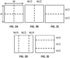
- each CTU is firstly partitioned by a quad-tree structure. Then, each quad-tree leaf node can be further partitioned by a binary and ternary tree structure. As shown in FIGS. 2A-2E , there are five splitting types, quaternary partitioning ( FIG. 2A ), horizontal binary partitioning ( FIG. 2B ), vertical binary partitioning ( FIG. 2C ), horizontal ternary partitioning ( FIG. 2D ), and vertical ternary partitioning ( FIG. 2E ).
- a prediction is formed based on either an inter prediction approach or an intra prediction approach.
- inter prediction one or more predictors are formed through motion estimation and motion compensation, based on pixels from previously reconstructed frames.
- intra prediction predictors are formed based on reconstructed pixels in a current frame. Through mode decision, a best predictor may be chosen to predict a current block.
- a prediction residual representing the difference between a current video block and its predictor, is sent to a Transform circuitry 102.
- Transform coefficients are then sent from the Transform circuitry 102 to a Quantization circuitry 104 for entropy reduction.
- Quantized coefficients are then fed to an Entropy Coding circuitry 106 to generate a compressed video bitstream.
- prediction-related information 110 from an inter prediction circuitry and/or an Intra Prediction circuitry 112 such as video block partition info, motion vectors, reference picture index, and intra prediction mode, are also fed through the Entropy Coding circuitry 106 and saved into a compressed video bitstream 114.
- decoder-related circuitries are also needed in order to reconstruct pixels for the purpose of prediction.
- a prediction residual is reconstructed through an Inverse Quantization 116 and an Inverse Transform circuitry 118.
- This reconstructed prediction residual is combined with a Block Predictor 120 to generate un-filtered reconstructed pixels for a current video block.
- Imaging prediction uses pixels from samples of already coded neighboring blocks (which are called reference samples) in the same video frame as the current video block to predict the current video block.
- Temporal prediction (also referred to as "inter prediction") uses reconstructed pixels from already-coded video pictures to predict the current video block. Temporal prediction reduces temporal redundancy inherent in the video signal.
- Temporal prediction signal for a given coding unit (CU) or coding block is usually signaled by one or more motion vectors (MVs) which indicate the amount and the direction of motion between the current CU and its temporal reference. Further, if multiple reference pictures are supported, one reference picture index is additionally sent, which is used to identify from which reference picture in the reference picture store the temporal prediction signal comes.
- MVs motion vectors
- an intra/inter mode decision circuitry 121 in the encoder 100 chooses the best prediction mode, for example based on the rate-distortion optimization method.
- the block predictor 120 is then subtracted from the current video block; and the resulting prediction residual is de-correlated using the transform circuitry 102 and the quantization circuitry 104.
- the resulting quantized residual coefficients are inverse quantized by the inverse quantization circuitry 116 and inverse transformed by the inverse transform circuitry 118 to form the reconstructed residual, which is then added back to the prediction block to form the reconstructed signal of the CU.
- in-loop filtering 115 such as a deblocking filter, a sample adaptive offset (SAO), and/or an adaptive in-loop filter (ALF) may be applied on the reconstructed CU before it is put in the reference picture store of the picture buffer 117 and used to code future video blocks.
- coding mode inter or intra
- prediction mode information motion information
- quantized residual coefficients are all sent to the entropy coding unit 106 to be further compressed and packed to form the bit-stream.
- a deblocking filter is available in AVC, HEVC as well as the now-current version of VVC.
- SAO sample adaptive offset
- SAO sample adaptive offset
- ALF adaptive loop filter
- These in-loop filter operations are optional. Performing these operations helps to improve coding efficiency and visual quality. They may also be turned off as a decision rendered by the encoder 100 to save computational complexity.
- intra prediction is usually based on unfiltered reconstructed pixels, while inter prediction is based on filtered reconstructed pixels if these filter options are turned on by the encoder 100.
- FIG. 3 is a block diagram illustrating an exemplary block-based video decoder 200 which may be used in conjunction with many video coding standards.
- This decoder 200 is similar to the reconstruction-related section residing in the encoder 100 of FIG. 1 .
- an incoming video bitstream 201 is first decoded through an Entropy Decoding 202 to derive quantized coefficient levels and prediction-related information.
- the quantized coefficient levels are then processed through an Inverse Quantization 204 and an Inverse Transform 206 to obtain a reconstructed prediction residual.
- a block predictor mechanism implemented in an Intra/inter Mode Selector 212, is configured to perform either an Intra Prediction 208, or a Motion Compensation 210, based on decoded prediction information.
- a set of unfiltered reconstructed pixels are obtained by summing up the reconstructed prediction residual from the Inverse Transform 206 and a predictive output generated by the block predictor mechanism, using a summer 214.
- the reconstructed block may further go through an In-Loop Filter 209 before it is stored in a Picture Buffer 213 which functions as a reference picture store.
- the reconstructed video in the Picture Buffer 213 may be sent to drive a display device, as well as used to predict future video blocks.
- a filtering operation is performed on these reconstructed pixels to derive a final reconstructed Video Output 222.
- the basic intra prediction scheme applied in the VVC is kept the same as that of the HEVC, except that several modules are further extended and/or improved, e.g., intra sub-partition (ISP) coding mode, extended intra prediction with wide-angle intra directions, position-dependent intra prediction combination (PDPC) and 4-tap intra interpolation.
- ISP intra sub-partition
- PDPC position-dependent intra prediction combination
- tile is defined as a rectangular region of CTUs within a particular tile column and a particular tile row in a picture.
- Tile group is a group of an integer number of tiles of a picture that are exclusively contained in a single NAL unit. Basically, the concept of tile group is the same as slice as defined in HEVC. For example, pictures are divided into tile groups and tiles.
- a tile is a sequence of CTUs that cover a rectangular region of a picture.
- a tile group contains a number of tiles of a picture.
- Two modes of tile groups are supported, namely the raster-scan tile group mode and the rectangular tile group mode.
- a tile group contains a sequence of tiles in tile raster scan of a picture.
- the rectangular tile group mode a tile group contains a number of tiles of a picture that collectively form a rectangular region of the picture.
- the tiles within a rectangular tile group are in the order of tile raster scan of the tile group.
- FIG. 4 shows an example of raster-scan tile group partitioning of a picture, where the picture is divided into 12 tiles and 3 raster-scan tile groups.
- FIG. 5 shows an example of rectangular tile group partitioning of a picture, where the picture is divided into 24 tiles (6 tile columns and 4 tile rows) and 9 rectangular tile groups.
- VTM4 large block-size transforms, up to 64 ⁇ 64 in size, are enabled, which is primarily useful for higher resolution video, e.g., 1080p and 4K sequences.
- High frequency transform coefficients are zeroed out for the transform blocks with size (width or height, or both width and height) equal to 64, so that only the lower-frequency coefficients are retained.
- M size
- N the block height
- transform skip mode is used for a large block, the entire block is used without zeroing out any values.
- VVC Virtual pipeline data units
- Virtual pipeline data units are defined as non-overlapping units in a picture.
- successive VPDUs are processed by multiple pipeline stages at the same time.
- the VPDU size is roughly proportional to the buffer size in most pipeline stages, so it is important to keep the VPDU size small.
- the VPDU size can be set to maximum transform block (TB) size.
- TB maximum transform block
- TT ternary tree
- BT binary tree
- VTM5 In order to keep the VPDU size as 64x64 luma samples, the following normative partition restrictions (with syntax signaling modification) are applied in VTM5, as shown in FIGS. 6A-6H .
- FIGS. 6A-6H For convenience, we label the examples in FIGS. 6A-6D from left to right for the upper examples, and FIGS. 6E-6H from left to right for the bottom examples.
- Transform coefficient coding refers to the coding process of transform coefficient quantization level values of a TU.
- transform coefficients of a coding block are coded using non-overlapped coefficient groups (or subblocks), and each CG contains the coefficients of a 4x4 block of a coding block.
- the CGs inside a coding block, and the transform coefficients within a CG, are coded according to pre-defined scan orders.
- the coding of transform coefficient levels of a CG with at least one non-zero transform coefficient may be separated into multiple scan passes. In the first pass, the first bin (denoted by bin0, also referred as significant_coeff_flag, which indicates the magnitude of the coefficient is greater than 0) is coded.
- the regular coded bins and the bypass coded bins are separated in coding order; first all regular coded bins for a subblock are transmitted and, thereafter, the bypass coded bins are transmitted.
- the transform coefficient levels of a subblock are coded in four passes over the scan positions as follows:
- the Rice parameter (ricePar) for coding the non-binary syntax element remainder (in Pass 3) is derived similar to HEVC. At the start of each subblock, ricePar is set equal to 0. After coding a syntax element remainder, the Rice parameter is modified according to predefined equation. For coding the non-binary syntax element absLevel (in Pass 4), the sum of absolute values sumAbs in a local template is determined. The variables ricePar and posZero are determined based on dependent quantization and sumAbs by a table look-up. The intermediate variable codeValue is derived as follows:
- transform coefficient coding is also referred as residual coding.
- Decoder-side Motion Vector Refinement is a technique for blocks coded in bi-prediction Merge mode and controlled by SPS signaling sps_dmvr_enabled_flag flag. Under this mode, the two motion vectors (MV) of the block can be further refined using bilateral matching (BM) prediction.
- BM bilateral matching
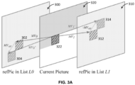
- FIG. 3A is a schematic diagram illustrating an example of decoder-side motion vector refinement (DMVR).
- the bilateral matching method is used to refine motion information of a current CU 322 in current picture 320 by searching the closest match between its two reference blocks 302, 312 along the motion trajectory of the current CU in its two associated reference pictures, i.e. refPic in List L0 300 and refPic in List L1 310.
- the patterned rectangular blocks 322, 302, and 312 indicate the current CU and its two reference blocks based on the initial motion information from Merge mode.
- the patterned rectangular blocks 304, 314 indicate one pair of reference blocks based on a MV candidate used in the motion refinement search process, i.e. motion vector refinement process.
- the MV differences between the MV candidate and the initial MV are MV diff and -MV diff , respectively.
- the MV candidate and the initial MV are both bi-directional motion vectors.
- a number of such MV candidates around the initial MV may be checked.
- its two associated reference blocks may be located from its reference pictures in List 0 and List 1 respectively, and the difference between them is calculated.
- Such block difference is usually measured in SAD (or sum of absolute difference), or row-subsampled SAD (i.e. the SAD calculated with every other row of the block involved).
- SAD sum of absolute difference
- SAD row-subsampled SAD
- the DMVR is applied to a CU that satisfies the following conditions:
- the refined MV derived by DMVR process is used to generate the inter prediction samples and also used in temporal motion vector prediction for future picture coding. While the original MV is used in deblocking process and also in spatial motion vector prediction for future CU coding.
- the bi-directional optical flow (BDOF) tool is included in VTM5.
- BDOF previously referred to as BIO, was included in the JEM.
- BIO was included in the JEM.
- the BDOF in VTM5 is a simpler version that requires much less computation, especially in terms of number of multiplications and the size of the multiplier.
- BDOF is controlling by SPS sps_bdof_enabled _flag flag.
- BDOF is used to refine the bi-prediction signal of a CU at the 4 ⁇ 4 sub-block level.
- BDOF is applied to a CU if it satisfies the following conditions: 1) the CU's height is not 4, and the CU is not in size of 4 ⁇ 8, 2) the CU is not coded using affine mode or the ATMVP merge mode; 3) the CU is coded using "true" bi-prediction mode, i.e., one of the two reference pictures is prior to the current picture in display order and the other is after the current picture in display order.
- BDOF is only applied to the luma component.
- the BDOF mode is based on the optical flow concept, which assumes that the motion of an object is smooth.
- the BDOF adjusts the prediction sample by calculated the gradient of current block to improve the coding efficiency.
- BDOF/DMVR are always applied if its SPS flag is enabled and some bi-prediction and size constrains are met for a regular merge candidate.
- DMVR is applied to a regular merge mode when all the following conditions are true:
- VTM5 allows the transform skip mode to be used for luma blocks of size up to 32x32 (inclusive).
- a CU When a CU is coded in transform skip mode, its prediction residual is quantized and coded using the transform skip residual coding process. This residual coding process is modified from the transform coefficient coding process described in the previous section.
- the residuals of a CU are also coded in units of non-overlapped subblocks of size 4x4. Different from the regular transform coefficient coding process, in transform skip mode, the last coefficient position is not signaled; instead, the coded_subblock_flag is signaled for all 4x4 subblocks in the CU in the forward scan order, i.e., from the top-left subblock to the last subblock.
- coded_subblock_flag 1 (i.e., there is at least one non-zero quantized residual in the subblock)
- coding of the quantized residual levels is performed in three scan passes:
- the bins in scan passes #1 and #2 are context coded until the maximum number of context coded bins in the CU have been exhausted.
- the maximum number of context coded bins in a residual block is limited to 2*block_width*block_height, or equivalently, 2 context coded bins per sample position on average.
- the bins in the last scan pass (the remainder scan pass) are bypass coded.
- the lossless coding mode in HEVC is achieved by simply bypassing transform, quantization, and in-loop filters (de-blocking filter, sample adaptive offset, and adaptive loop filter).
- the design is aimed to enable the lossless coding with minimum changes required to the regular HEVC encoder and decoder implementation for mainstream applications.
- the lossless coding mode can be turned on or off at the individual CU level. This is done through a syntax cutransquant_bypass_flag signaled at CU level.
- the cu_transquant_bypass _flag syntax is not always signaled. It is signaled only when another syntax called transquant_bypass_enabled_flag has a value of 1. In other words, the syntax transquant_bypass_enabled_flag is used to turn on the syntax signaling of cu_transquant_bypass_flag.
- the syntax _transquant_bypass_enabled_flag is signaled in the picture parameter set (PPS) to indicate whether the syntax cu_transquant_bypass_flag needs to be signaled for every CU inside a picture referring to the PPS. If this flag is set equal to 1, the syntax cu_transquant_bypass _flag is sent at the CU level to signal whether the current CU is coded with the lossless mode or not. If this flag is set equal to 0 in the PPS, cu_transquant_bypass_flag is not sent, and all the CUs in the picture are encoded with transform, quantization, and loop filters involved in the process, which will generally result in a certain level of video quality degradation.
- PPS picture parameter set
- the maximum CU size is 64x64 and the VPDU is also set as 64x64.
- the maximum block size for coefficients coding in VVC is 32x32 because of the coefficient zero-out mechanism for width/height greater than 32.
- current transform skip only supports up to 32x32 CU so that the maximum block size for residual coding can be aligned with the maximum block size for coefficient coding which is 32x32.
- the constraint for the block size of residual coding for a lossless CU is not defined. As a result, currently in VVC it is possible to generate a residual block under lossless coding mode with a size greater than 32x32, which would require the support of residual coding for blocks greater than 32x32. This is not preferred for the codec implementation. In this disclosure, several methods are proposed to address this issue.
- Another issue associated with lossless coding support in VVC is how to choose the residual (or referred as coefficient) coding scheme.
- the selection of residual coding scheme is based on the transform skip flag of a given block (or CU). Therefore, if under lossless mode the transform skip flag is assumed to be 1 in VVC as in HEVC, the residual coding scheme used under transform skip mode would be always used for a lossless mode CU.
- the current residual coding scheme used when the transform skip flag is true is designed mainly for screen content coding. It may not be optimal to be used for lossless coding of regular content (i.e. non-screen content). In this disclosure, several methods are proposed to select the residual coding for lossless CUs.
- the transform skip mode can only be enabled for a residual block whose width and height are both smaller than or equal to 32, which means the maximum residual coding block size under transform skip mode is 32x32.
- the maximum width and/or height of the residual block for a lossless CU is also set to be 32, with a maximum residual block size as 32x32.
- the CU residual block is divided into multiple smaller residual blocks with a size of 32xN and/or Nx32 so that the width or height of the smaller residual blocks are not greater than 32.
- a 128x32 lossless CU is divided into four 32x32 residual blocks for residual coding.
- a 64x64 lossless CU is divided into four 32x32 residual blocks.
- the width/height of maximum residual block for lossless CU is set to the VPDU size (e.g. 64x64 in current VVC).
- the CU residual block is divided into multiple smaller residual blocks with a size of 64xN and/or Nx64 so that the width or height of the smaller residual blocks are not greater than VPDU width and/or height.
- a 128x128 lossless CU is divided into four 64x64 residual blocks for residual coding.
- a 128x32 lossless CU is divided into two 64x32 residual blocks.
- a lossless CU uses the same residual coding scheme as the one used by the transform skip mode CUs.
- a lossless CU uses the same residual coding scheme as the one used by the non-transform skip mode CUs.
- the residual coding scheme for lossless CUs is selected adaptively from the existing residual coding schemes based on certain conditions and/or predefined procedures. Such conditions and/or predefined procedures are followed by both the encoder and decoder, so that there is no signaling needed in the bitstream to indicate the selection.
- a simple screen content detection scheme may be specified and utilized in both encoder and decoder. Based on the detection scheme, a current video block may be classified as screen content or regular content. In case it is screen content, the residual coding scheme used under transform skip mode is selected. Otherwise, the other residual coding scheme is selected.
- syntax is signaled in the bitstream to explicitly specify which residual coding scheme is used by a lossless CU.
- a syntax may be a binary flag, with each binary value indicating the selection of one of the two residual coding schemes.
- the syntax can be signaled at different levels. For example, it may be signaled in sequence parameter set (SPS), picture parameter set (PPS), slice header, tiles group header, or tile. It may also be signaled at CTU or CU level.
- SPS sequence parameter set
- PPS picture parameter set
- slice header tiles group header, or tile. It may also be signaled at CTU or CU level.
- all the lossless CUs at the same or lower level would use the same residual coding scheme indicated by the syntax.
- the syntax is signaled at SPS level, all the lossless CUs in the sequence would use the same residual coding scheme indicated.
- the syntax indicating residual coding scheme is conditionally signaled based on the lossless mode flag of the CU. For example, only when the lossless mode flag cu_transquant_bypass _flag indicates that the current CU is coded in lossless mode, the syntax indicating residual coding scheme is signaled for the CU.
- the residual coding scheme for each one of the plurality of CUs is selected based on the signaled first flag, where the residual coding scheme selected for the lossless CU is the residual coding scheme used by transform skip mode CUs or the non-transform skip mode CUs depending on the signaled flag at the slice header.
- a transform skip mode flag is signaled.
- the selection of residual coding scheme for the CU is based on its transform skip mode flag.
- the controlling of DMVR on/off is not defined for lossless coding mode.
- it is proposed to control turn on/off DMVR in slice level by a 1-bit signaling slice_disable_dmvr_flag flag.
- the slice_disable_dmvr_flag flag is needed to be signaled if sps_dmvr_enabled_flag is set equal to 1 and transquant_bypass_enabled_flag flag is set equal to 0. If slice_disable_dmvr_flag flag is not signaled, it is inferred to be 1. If slice_disable_dmvr_flag is equal to 1, DMVR is turned off.
- the signaling is as followed: if( sps_dmvr_enabled _flag && !transquant_bypass_enabled_flag) slice_disable_dmvr_flag u(1)
- DMVR is applied to a regular merge mode when all the following conditions are true:
- the controlling of BDOF on/off is not defined for lossless coding mode.
- it is proposed to control turn on/off BDOF by a 1-bit signaling slice_disable_bdof_flag flag.
- the slice_disable_bdof_flag flag is signaled if sps_bdof_enabled_flag is set equal to 1 or transquant_bypass_enabled_flag flag is set equal to 0. If slice_disable_bdof_flag flag is not signaled, it is inferred to be 1. If slice_disable_bdof_flag flag is equal to 1, BDOF is disable.
- the signaling is illustrated as follows: if( sps_bdof_enabled _flag && !transquant_bypass_enabled_flag) slice_disable_bdof_flag u(1)
- BDOF is applied to a regular merge mode when all the following conditions are true:
- both of BDOF and DMVR are always applied for decoder-side refinement to improve coding efficiency and controlled by each SPS flag and condition of some bi-prediction and size constrains are met for a regular merge candidate.
- slice_disable_bdof_dmvr_flag is signaled if following condition is met. if( (sps_bdof_enabled _flag ⁇ sps_dmvr_enabled _flag) && !transquant_bypass_enabled_flag ) slice_disable_bdof_dmvr_flag u(1)
- the above methods may be implemented using an apparatus that includes one or more circuitries, which include application specific integrated circuits (ASICs), digital signal processors (DSPs), digital signal processing devices (DSPDs), programmable logic devices (PLDs), field programmable gate arrays (FPGAs), controllers, micro-controllers, microprocessors, or other electronic components.
- the apparatus may use the circuitries in combination with the other hardware or software components for performing the above described methods.
- Each module, sub-module, unit, or sub-unit disclosed above may be implemented at least partially using the one or more circuitries.
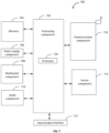
- FIG. 7 is a block diagram illustrating an apparatus for video coding in accordance with some implementations of the present disclosure.
- the apparatus 700 may be a terminal, such as a mobile phone, a tablet computer, a digital broadcast terminal, a tablet device, or a personal digital assistant.
- the apparatus 700 may include one or more of the following components: a processing component 702, a memory 704, a power supply component 706, a multimedia component 708, an audio component 710, an input/output (I/O) interface 712, a sensor component 714, and a communication component 716.
- the processing component 702 usually controls overall operations of the apparatus 700, such as operations relating to display, a telephone call, data communication, a camera operation and a recording operation.
- the processing component 702 may include one or more processors 720 for executing instructions to complete all or a part of steps of the above method.
- the processing component 702 may include one or more modules to facilitate interaction between the processing component 702 and other components.
- the processing component 702 may include a multimedia module to facilitate the interaction between the multimedia component 708 and the processing component 702.
- the memory 704 is configured to store different types of data to support operations of the apparatus 700. Examples of such data include instructions, contact data, phonebook data, messages, pictures, videos, and so on for any application or method that operates on the apparatus 700.
- the memory 704 may be implemented by any type of volatile or non-volatile storage devices or a combination thereof, and the memory 704 may be a Static Random Access Memory (SRAM), an Electrically Erasable Programmable Read-Only Memory (EEPROM), an Erasable Programmable Read-Only Memory (EPROM), a Programmable Read-Only Memory (PROM), a Read-Only Memory (ROM), a magnetic memory, a flash memory, a magnetic disk or a compact disk.
- SRAM Static Random Access Memory
- EEPROM Electrically Erasable Programmable Read-Only Memory
- EPROM Erasable Programmable Read-Only Memory
- PROM Programmable Read-Only Memory
- ROM Read-Only Memory
- the power supply component 706 supplies power for different components of the apparatus 700.
- the power supply component 706 may include a power supply management system, one or more power supplies, and other components associated with generating, managing and distributing power for the apparatus 700.
- the multimedia component 708 includes a screen providing an output interface between the apparatus 700 and a user.
- the screen may include a Liquid Crystal Display (LCD) and a Touch Panel (TP). If the screen includes a touch panel, the screen may be implemented as a touch screen receiving an input signal from a user.
- the touch panel may include one or more touch sensors for sensing a touch, a slide and a gesture on the touch panel. The touch sensor may not only sense a boundary of a touching or sliding actions, but also detect duration and pressure related to the touching or sliding operation.
- the multimedia component 708 may include a front camera and/or a rear camera. When the apparatus 700 is in an operation mode, such as a shooting mode or a video mode, the front camera and/or the rear camera may receive external multimedia data.
- the audio component 710 is configured to output and/or input an audio signal.
- the audio component 710 includes a microphone (MIC).
- the microphone When the apparatus 700 is in an operating mode, such as a call mode, a recording mode and a voice recognition mode, the microphone is configured to receive an external audio signal.
- the received audio signal may be further stored in the memory 704 or sent via the communication component 716.
- the audio component 710 further includes a speaker for outputting an audio signal.
- the I/O interface 712 provides an interface between the processing component 702 and a peripheral interface module.
- the above peripheral interface module may be a keyboard, a click wheel, a button, or the like. These buttons may include but not limited to, a home button, a volume button, a start button and a lock button.
- the sensor component 714 includes one or more sensors for providing a state assessment in different aspects for the apparatus 700.
- the sensor component 714 may detect an on/off state of the apparatus 700 and relative locations of components.
- the components are a display and a keypad of the apparatus 700.
- the sensor component 714 may also detect a position change of the apparatus 700 or a component of the apparatus 700, presence or absence of a contact of a user on the apparatus 700, an orientation or acceleration/deceleration of the apparatus 700, and a temperature change of apparatus 700.
- the sensor component 714 may include a proximity sensor configured to detect presence of a nearby object without any physical touch.
- the sensor component 714 may further include an optical sensor, such as a CMOS or CCD image sensor used in an imaging application.
- the sensor component 714 may further include an acceleration sensor, a gyroscope sensor, a magnetic sensor, a pressure sensor, or a temperature sensor.
- the communication component 716 is configured to facilitate wired or wireless communication between the apparatus 700 and other devices.
- the apparatus 700 may access a wireless network based on a communication standard, such as WiFi, 4G, or a combination thereof.
- the communication component 716 receives a broadcast signal or broadcast related information from an external broadcast management system via a broadcast channel.
- the communication component 716 may further include a Near Field Communication (NFC) module for promoting short-range communication.
- NFC Near Field Communication
- the NFC module may be implemented based on Radio Frequency Identification (RFID) technology, infrared data association (IrDA) technology, Ultra-Wide Band (UWB) technology, Bluetooth (BT) technology and other technology.
- RFID Radio Frequency Identification
- IrDA infrared data association
- UWB Ultra-Wide Band
- Bluetooth Bluetooth
- the apparatus 700 may be implemented by one or more of Application Specific Integrated Circuits (ASIC), Digital Signal Processors (DSP), Digital Signal Processing Devices (DSPD), Programmable Logic Devices (PLD), Field Programmable Gate Arrays (FPGA), controllers, microcontrollers, microprocessors or other electronic elements to perform the above method.
- ASIC Application Specific Integrated Circuits
- DSP Digital Signal Processors
- DSPD Digital Signal Processing Devices
- PLD Programmable Logic Devices
- FPGA Field Programmable Gate Arrays
- controllers microcontrollers, microprocessors or other electronic elements to perform the above method.
- a non-transitory computer readable storage medium may be, for example, a Hard Disk Drive (HDD), a Solid-State Drive (SSD), Flash memory, a Hybrid Drive or Solid-State Hybrid Drive (SSHD), a Read-Only Memory (ROM), a Compact Disc Read-Only Memory (CD-ROM), a magnetic tape, a floppy disk and etc.
- HDD Hard Disk Drive
- SSD Solid-State Drive
- SSHD Solid-State Hybrid Drive
- ROM Read-Only Memory
- CD-ROM Compact Disc Read-Only Memory
- magnetic tape a floppy disk and etc.
- FIG. 8 is a flowchart illustrating an exemplary process of techniques relating to lossless coding modes in video coding in accordance with some implementations of the present disclosure.
- step 801 the processor 720 partitions a video picture into a plurality of coding units (CUs), at least one of which is a lossless CU.
- CUs coding units
- step 802 the processor 720 determines a residual coding block size of the lossless CU.
- step 803 the processor 720 splits the residual coding block into two or more residual blocks for residual coding, in response to determining that the residual coding block size of the lossless CU is greater than a predefined maximum value.
- an apparatus for video coding includes a processor 720; and a memory 704 configured to store instructions executable by the processor; where the processor, upon execution of the instructions, is configured to perform a method as illustrated in FIG. 8 .
- a non-transitory computer readable storage medium 704 having instructions stored therein.
- the instructions When the instructions are executed by a processor 720, the instructions cause the processor to perform a method as illustrated in FIG. 8 .
- FIG. 9 is a flowchart illustrating an exemplary process of techniques relating to lossless coding modes in video coding in accordance with some implementations of the present disclosure.
- step 901 the processor 720 partitions a video picture into a plurality of coding units (CUs), at least one of which is a lossless CU.
- CUs coding units
- step 902 the processor 720 selects a residual coding scheme for the lossless CU, wherein the residual coding scheme selected for the lossless CU is same as the residual coding scheme used by non-transform skip mode CUs.
- an apparatus for video coding includes a processor 720; and a memory 704 configured to store instructions executable by the processor; where the processor, upon execution of the instructions, is configured to perform a method as illustrated in FIG. 9 .
- a non-transitory computer readable storage medium 704 having instructions stored therein.
- the instructions When the instructions are executed by a processor 720, the instructions cause the processor to perform a method as illustrated in FIG. 9 .
Landscapes
- Engineering & Computer Science (AREA)
- Multimedia (AREA)
- Signal Processing (AREA)
- Physics & Mathematics (AREA)
- Discrete Mathematics (AREA)
- General Physics & Mathematics (AREA)
- Compression Or Coding Systems Of Tv Signals (AREA)
Claims (12)
- Verfahren zur Videodecodierung, aufweisend die Schritte:Bestimmen, ob sich ein aktueller Block in einem verlustfreien Modus befindet, basierend auf einer ersten Anzeige im Bitstrom, die angibt, ob der aktuelle Block verlustfrei codiert ist;dadurch gekennzeichnet, dass als Reaktion auf die Feststellung, dass sich der aktuelle Block im verlustfreien Modus befindet, bestimmt wird, ob ein erstes Residualcodierungsverfahren oder ein zweites Residualcodierungsverfahren für den aktuellen Block im verlustfreien Modus angewendet wird, und zwar auf der Grundlage einer zweiten Anzeige im Bitstrom, die angibt, welches Residualcodierungsverfahren verwendet wird;wobei das erste Residualcodierungsverfahren ein Residualcodierungsverfahren ist, das für einen Nicht-Transform-Skip-Block vordefiniert ist, und das zweite Residualcodierungsverfahren ein Residualcodierungsverfahren ist, das für einen Transform-Skip-Block vordefiniert ist.
- Verfahren zur Videodecodierung nach Anspruch 1, weiterhin aufweisend:
Empfangen eines 1-Bit-Flags für den aktuellen Block zur Steuerung des Ein- und Ausschaltens der decoderseitigen Bewegungsvektorverfeinerung (DMVR) auf Scheiben- oder Bildebene. - Verfahren zur Videodecodierung nach einem von Anspruch 1, weiterhin aufweisend:
Empfangen eines 1-Bit-Flags für den aktuellen Block zur Steuerung des Ein- und Ausschaltens der decoderseitigen Bewegungsvektorverfeinerung (DMVR) auf einer Ebene der Codiereinheit (CU). - Verfahren zur Videodecodierung nach einem der vorhergehenden Ansprüche 1 bis 3, weiterhin aufweisend: Empfangen eines 1-Bit-Flags für den aktuellen Block zur Steuerung des Ein- und Ausschaltens des bidirektionalen optischen Flusses (BDOF) auf Scheiben- oder Bildebene.
- Verfahren zur Videodecodierung nach einem der vorhergehenden Ansprüche 1 bis 3, weiterhin aufweisend: Empfangen eines 1-Bit-Flags für den aktuellen Block zur Steuerung des Ein- und Ausschaltens des bidirektionalen optischen Flusses (BDOF) auf einer Ebene der Codiereinheit (CU).
- Verfahren zur Videodecodierung nach Anspruch 1, weiterhin aufweisend:
Empfangen eines 1-Bit-Flags für den aktuellen Block zur Steuerung des Ein- und Ausschaltens der decoderseitigen Bewegungsvektorverfeinerung (DMVR) und des bidirektionalen optischen Flusses (BDOF) auf Scheiben- oder Bildebene. - Vorrichtung (700) zur Videodecodierung, aufweisend:ein oder mehrere Prozessoren (720); undeinen Speicher (704), der ausgebildet ist, um Befehle zu speichern, die von einem oder mehreren Prozessoren (720) ausgeführt werden können; wobei der eine Prozessor oder die mehreren Prozessoren (720) nach Ausführung der Befehle für Folgendes ausgebildet sind:Bestimmen, ob sich ein aktueller Block in einem verlustfreien Modus befindet, basierend auf einer ersten Anzeige im Bitstrom, die angibt, ob der aktuelle Block verlustfrei codiert ist;dadurch gekennzeichnet, dass als Reaktion auf die Feststellung, dass sich der aktuelle Block im verlustfreien Modus befindet, bestimmt wird, ob ein erstes Residualcodierungsverfahren oder ein zweites Residualcodierungsverfahren für den aktuellen Block im verlustfreien Modus angewendet wird, und zwar auf der Grundlage einer zweiten Anzeige im Bitstrom, die angibt, welches Residualcodierungsverfahren verwendet wird;wobei das erste Residualcodierungsverfahren ein Residualcodierungsverfahren ist, das für einen Nicht-Transform-Skip-Block vordefiniert ist, und das zweite Residualcodierungsverfahren ein Residualcodierungsverfahren ist, das für einen Transform-Skip-Block vordefiniert ist.
- Vorrichtung (700) zur Videodecodierung nach Anspruch 7, wobei der eine Prozessor oder die mehreren Prozessoren (720) bei Ausführung der Anweisungen weiterhin für Folgendes ausgebildet sind:
Empfangen eines 1-Bit-Flags für den aktuellen Block, um das Ein- und Ausschalten der decoderseitigen Bewegungsvektorverfeinerung (DMVR) auf Scheiben- oder Bildebene zu steuern. - Vorrichtung (700) zur Videodecodierung nach einem der Ansprüche 7, wobei der eine Prozessor oder die mehreren Prozessoren (720) bei Ausführung der Anweisungen weiterhin für Folgendes ausgebildet sind:
Empfangen eines 1-Bit-Flags für den aktuellen Block, um das Ein- und Ausschalten der decoderseitigen Bewegungsvektorverfeinerung (DMVR) auf einer Ebene der Codiereinheit (CU) zu steuern. - Vorrichtung (700) zur Videodecodierung nach einem der vorhergehenden Ansprüche 7 bis 9, wobei der eine Prozessor oder die mehreren Prozessoren (720) bei Ausführung der Anweisungen weiterhin für Folgendes ausgebildet sind:
Empfangen eines 1-Bit-Flags für den aktuellen Block, um das Ein- und Ausschalten des bidirektionalen optischen Flusses (BDOF) auf Scheiben- oder Bildebene zu steuern. - Vorrichtung (700) zur Videodecodierung nach einem der vorhergehenden Ansprüche 7 bis 9, wobei der eine Prozessor oder die mehreren Prozessoren (720) bei Ausführung der Anweisungen weiterhin für Folgendes ausgebildet sind:
Empfangen eines 1-Bit-Flags für den aktuellen Block zur Steuerung des Ein- und Ausschaltens des bidirektionalen optischen Flusses (BDOF) auf einer Ebene der Codiereinheit (CU). - Nichtflüchtiges computerlesbares Speichermedium, das eine Vielzahl von Programmen zur Ausführung durch eine Rechenvorrichtung mit einem oder mehreren Prozessoren (720) speichert, wobei die Vielzahl von Programmen, wenn sie von einem oder mehreren Prozessoren (720) ausgeführt werden, die Rechenvorrichtung veranlasst, das Verfahren zur Videodecodierung nach einem der Ansprüche 1-6 auszuführen, um einen Bitstrom zu verarbeiten.
Applications Claiming Priority (3)
| Application Number | Priority Date | Filing Date | Title |
|---|---|---|---|
| US201962868857P | 2019-06-28 | 2019-06-28 | |
| US201962871134P | 2019-07-06 | 2019-07-06 | |
| PCT/US2020/040195 WO2020264529A1 (en) | 2019-06-28 | 2020-06-29 | Lossless coding modes for video coding |
Publications (4)
| Publication Number | Publication Date |
|---|---|
| EP3973704A1 EP3973704A1 (de) | 2022-03-30 |
| EP3973704A4 EP3973704A4 (de) | 2022-07-27 |
| EP3973704B1 true EP3973704B1 (de) | 2025-04-16 |
| EP3973704C0 EP3973704C0 (de) | 2025-04-16 |
Family
ID=74059652
Family Applications (1)
| Application Number | Title | Priority Date | Filing Date |
|---|---|---|---|
| EP20831339.5A Active EP3973704B1 (de) | 2019-06-28 | 2020-06-29 | Verlustfreie codierungsmodi zur videocodierung |
Country Status (8)
| Country | Link |
|---|---|
| US (2) | US12477121B2 (de) |
| EP (1) | EP3973704B1 (de) |
| JP (2) | JP7769547B2 (de) |
| KR (2) | KR102580875B1 (de) |
| CN (2) | CN115567708A (de) |
| ES (1) | ES3025961T3 (de) |
| MX (1) | MX2021015957A (de) |
| WO (1) | WO2020264529A1 (de) |
Families Citing this family (3)
| Publication number | Priority date | Publication date | Assignee | Title |
|---|---|---|---|---|
| FR3086485A1 (fr) * | 2018-09-21 | 2020-03-27 | Orange | Procedes et dispositifs de codage et de decodage d'un flux de donnees representatif d'au moins une image. |
| US20220256151A1 (en) * | 2019-08-23 | 2022-08-11 | Sony Group Corporation | Image processing device and method |
| KR102929853B1 (ko) | 2019-09-09 | 2026-02-23 | 두인 비전 컴퍼니 리미티드 | 인트라 블록 복제 코딩 및 디코딩 |
Family Cites Families (13)
| Publication number | Priority date | Publication date | Assignee | Title |
|---|---|---|---|---|
| KR100823287B1 (ko) * | 2007-01-03 | 2008-04-21 | 삼성전자주식회사 | 전역 차이 벡터를 이용한 다시점 영상의 부호화, 복호화방법 및 장치 |
| US10397577B2 (en) * | 2011-03-08 | 2019-08-27 | Velos Media, Llc | Inverse scan order for significance map coding of transform coefficients in video coding |
| CN104170385B (zh) * | 2012-02-06 | 2019-02-19 | 诺基亚技术有限公司 | 用于编码的方法和装置 |
| US20130294524A1 (en) * | 2012-05-04 | 2013-11-07 | Qualcomm Incorporated | Transform skipping and lossless coding unification |
| CN105122797A (zh) * | 2013-01-04 | 2015-12-02 | 三星电子株式会社 | 在无损编码下对视频进行编码的方法和设备以及在无损编码下对视频进行解码的方法和设备 |
| KR102013561B1 (ko) * | 2013-04-23 | 2019-08-23 | 퀄컴 인코포레이티드 | 비디오 코딩에서 예측 잔차 블록들의 재배치 |
| WO2015055111A1 (en) * | 2013-10-14 | 2015-04-23 | Mediatek Inc. | Method of lossless mode signaling for video system with lossless and lossy coding |
| EP4250727A3 (de) * | 2014-03-16 | 2023-12-06 | Vid Scale, Inc. | Verfahren und vorrichtung zur signalisierung von verlustfreier videocodierung |
| CN113170093B (zh) * | 2018-11-20 | 2023-05-02 | 北京字节跳动网络技术有限公司 | 视频处理中的细化帧间预测 |
| WO2020185842A1 (en) * | 2019-03-11 | 2020-09-17 | Vid Scale, Inc. | Methods and apparatus for sub-picture adaptive resolution change |
| US11451826B2 (en) * | 2019-04-15 | 2022-09-20 | Tencent America LLC | Lossless coding mode and switchable residual coding |
| CN120075432A (zh) * | 2019-06-18 | 2025-05-30 | 韩国电子通信研究院 | 视频编码/解码方法以及发送压缩视频数据的设备 |
| EP3987785A1 (de) * | 2019-06-20 | 2022-04-27 | InterDigital VC Holdings France, SAS | Verlustfreier modus zur vielseitigen videocodierung |
-
2020
- 2020-06-29 CN CN202210161569.0A patent/CN115567708A/zh active Pending
- 2020-06-29 EP EP20831339.5A patent/EP3973704B1/de active Active
- 2020-06-29 KR KR1020217043013A patent/KR102580875B1/ko active Active
- 2020-06-29 JP JP2021577674A patent/JP7769547B2/ja active Active
- 2020-06-29 ES ES20831339T patent/ES3025961T3/es active Active
- 2020-06-29 MX MX2021015957A patent/MX2021015957A/es unknown
- 2020-06-29 WO PCT/US2020/040195 patent/WO2020264529A1/en not_active Ceased
- 2020-06-29 CN CN202080043764.2A patent/CN113994673A/zh active Pending
- 2020-06-29 KR KR1020237031708A patent/KR20230135187A/ko active Pending
-
2021
- 2021-12-23 US US17/561,577 patent/US12477121B2/en active Active
-
2024
- 2024-03-07 JP JP2024034773A patent/JP7799730B2/ja active Active
-
2025
- 2025-10-23 US US19/367,184 patent/US20260059117A1/en active Pending
Also Published As
| Publication number | Publication date |
|---|---|
| CN115567708A (zh) | 2023-01-03 |
| JP7799730B2 (ja) | 2026-01-15 |
| US20260059117A1 (en) | 2026-02-26 |
| JP2024069342A (ja) | 2024-05-21 |
| KR20230135187A (ko) | 2023-09-22 |
| JP7769547B2 (ja) | 2025-11-13 |
| KR20220000962A (ko) | 2022-01-04 |
| US20220124347A1 (en) | 2022-04-21 |
| US12477121B2 (en) | 2025-11-18 |
| WO2020264529A1 (en) | 2020-12-30 |
| KR102580875B1 (ko) | 2023-09-20 |
| EP3973704A4 (de) | 2022-07-27 |
| JP2022538331A (ja) | 2022-09-01 |
| MX2021015957A (es) | 2022-02-03 |
| CN113994673A (zh) | 2022-01-28 |
| EP3973704A1 (de) | 2022-03-30 |
| ES3025961T3 (en) | 2025-06-10 |
| EP3973704C0 (de) | 2025-04-16 |
Similar Documents
| Publication | Publication Date | Title |
|---|---|---|
| CN113812148B (zh) | 用于视频译码的参考图片重采样和帧间译码工具 | |
| CN114128261B (zh) | 用于视频译码的组合的帧间和帧内预测模式 | |
| CN113940079B (zh) | 用于视频译码的基于梯度的预测细化 | |
| CN114731418B (zh) | 联合色度残差视频译码 | |
| CN113508594A (zh) | 视频编解码中三角形合并模式索引的信令 | |
| JP7691936B2 (ja) | ビデオコーディングのための勾配ベースの予測改良 | |
| US20260059117A1 (en) | Lossless coding modes for video coding | |
| CN113924776B (zh) | 使用不同的色度格式的具有未经滤波的参考样本的视频译码 | |
| CN112771860B (zh) | 针对视频译码中最差情况的带宽减少的仿射限制 | |
| US20250088658A1 (en) | Methods and apparatuses for signaling of syntax elements in video coding | |
| CN113170162B (zh) | 用于视频译码的共享候选列表和并行候选列表推导 | |
| CN113892264A (zh) | 使用非矩形预测模式来减少用于视频数据预测的运动场存储 | |
| CN113994674B (zh) | 增加经帧内译码的块的解码吞吐 | |
| KR20210088697A (ko) | 인코더, 디코더 및 대응하는 디블록킹 필터 적응의 방법 | |
| CN114827605A (zh) | 用于视频解码的方法和计算设备 | |
| WO2021072375A1 (en) | Methods and apparatuses for video coding using triangle partition | |
| CN116708802B (zh) | 用于针对视频编解码的预测相关残差缩放的方法和设备 | |
| HK40065522A (en) | Combined inter and intra prediction mode for video coding | |
| HK40062582A (en) | Gradient-based prediction refinement for video coding |
Legal Events
| Date | Code | Title | Description |
|---|---|---|---|
| STAA | Information on the status of an ep patent application or granted ep patent |
Free format text: STATUS: THE INTERNATIONAL PUBLICATION HAS BEEN MADE |
|
| PUAI | Public reference made under article 153(3) epc to a published international application that has entered the european phase |
Free format text: ORIGINAL CODE: 0009012 |
|
| STAA | Information on the status of an ep patent application or granted ep patent |
Free format text: STATUS: REQUEST FOR EXAMINATION WAS MADE |
|
| 17P | Request for examination filed |
Effective date: 20211224 |
|
| AK | Designated contracting states |
Kind code of ref document: A1 Designated state(s): AL AT BE BG CH CY CZ DE DK EE ES FI FR GB GR HR HU IE IS IT LI LT LU LV MC MK MT NL NO PL PT RO RS SE SI SK SM TR |
|
| RIN1 | Information on inventor provided before grant (corrected) |
Inventor name: XIU, XIAOYU Inventor name: WANG, XIANGLIN Inventor name: MA, TSUNG-CHUAN Inventor name: CHEN, YI-WEN |
|
| STAA | Information on the status of an ep patent application or granted ep patent |
Free format text: STATUS: EXAMINATION IS IN PROGRESS |
|
| A4 | Supplementary search report drawn up and despatched |
Effective date: 20220629 |
|
| RIC1 | Information provided on ipc code assigned before grant |
Ipc: H04N 19/513 20140101ALI20220623BHEP Ipc: H04N 19/573 20140101ALI20220623BHEP Ipc: H04N 19/70 20140101ALI20220623BHEP Ipc: H04N 19/122 20140101ALI20220623BHEP Ipc: H04N 19/119 20140101AFI20220623BHEP |
|
| 17Q | First examination report despatched |
Effective date: 20220704 |
|
| DAV | Request for validation of the european patent (deleted) | ||
| DAX | Request for extension of the european patent (deleted) | ||
| GRAP | Despatch of communication of intention to grant a patent |
Free format text: ORIGINAL CODE: EPIDOSNIGR1 |
|
| STAA | Information on the status of an ep patent application or granted ep patent |
Free format text: STATUS: GRANT OF PATENT IS INTENDED |
|
| INTG | Intention to grant announced |
Effective date: 20241111 |
|
| GRAS | Grant fee paid |
Free format text: ORIGINAL CODE: EPIDOSNIGR3 |
|
| GRAA | (expected) grant |
Free format text: ORIGINAL CODE: 0009210 |
|
| STAA | Information on the status of an ep patent application or granted ep patent |
Free format text: STATUS: THE PATENT HAS BEEN GRANTED |
|
| AK | Designated contracting states |
Kind code of ref document: B1 Designated state(s): AL AT BE BG CH CY CZ DE DK EE ES FI FR GB GR HR HU IE IS IT LI LT LU LV MC MK MT NL NO PL PT RO RS SE SI SK SM TR |
|
| REG | Reference to a national code |
Ref country code: GB Ref legal event code: FG4D |
|
| REG | Reference to a national code |
Ref country code: CH Ref legal event code: EP Ref country code: DE Ref legal event code: R096 Ref document number: 602020049659 Country of ref document: DE |
|
| REG | Reference to a national code |
Ref country code: IE Ref legal event code: FG4D |
|
| REG | Reference to a national code |
Ref country code: ES Ref legal event code: FG2A Ref document number: 3025961 Country of ref document: ES Kind code of ref document: T3 Effective date: 20250610 |
|
| U01 | Request for unitary effect filed |
Effective date: 20250508 |
|
| U07 | Unitary effect registered |
Designated state(s): AT BE BG DE DK EE FI FR IT LT LU LV MT NL PT RO SE SI Effective date: 20250516 |
|
| PGFP | Annual fee paid to national office [announced via postgrant information from national office to epo] |
Ref country code: GB Payment date: 20250618 Year of fee payment: 6 |
|
| U20 | Renewal fee for the european patent with unitary effect paid |
Year of fee payment: 6 Effective date: 20250627 |
|
| PGFP | Annual fee paid to national office [announced via postgrant information from national office to epo] |
Ref country code: ES Payment date: 20250731 Year of fee payment: 6 |
|
| PG25 | Lapsed in a contracting state [announced via postgrant information from national office to epo] |
Ref country code: GR Free format text: LAPSE BECAUSE OF FAILURE TO SUBMIT A TRANSLATION OF THE DESCRIPTION OR TO PAY THE FEE WITHIN THE PRESCRIBED TIME-LIMIT Effective date: 20250717 Ref country code: NO Free format text: LAPSE BECAUSE OF FAILURE TO SUBMIT A TRANSLATION OF THE DESCRIPTION OR TO PAY THE FEE WITHIN THE PRESCRIBED TIME-LIMIT Effective date: 20250716 |
|
| PG25 | Lapsed in a contracting state [announced via postgrant information from national office to epo] |
Ref country code: PL Free format text: LAPSE BECAUSE OF FAILURE TO SUBMIT A TRANSLATION OF THE DESCRIPTION OR TO PAY THE FEE WITHIN THE PRESCRIBED TIME-LIMIT Effective date: 20250416 |
|
| PG25 | Lapsed in a contracting state [announced via postgrant information from national office to epo] |
Ref country code: HR Free format text: LAPSE BECAUSE OF FAILURE TO SUBMIT A TRANSLATION OF THE DESCRIPTION OR TO PAY THE FEE WITHIN THE PRESCRIBED TIME-LIMIT Effective date: 20250416 |
|
| PG25 | Lapsed in a contracting state [announced via postgrant information from national office to epo] |
Ref country code: RS Free format text: LAPSE BECAUSE OF FAILURE TO SUBMIT A TRANSLATION OF THE DESCRIPTION OR TO PAY THE FEE WITHIN THE PRESCRIBED TIME-LIMIT Effective date: 20250716 |
|
| PG25 | Lapsed in a contracting state [announced via postgrant information from national office to epo] |
Ref country code: IS Free format text: LAPSE BECAUSE OF FAILURE TO SUBMIT A TRANSLATION OF THE DESCRIPTION OR TO PAY THE FEE WITHIN THE PRESCRIBED TIME-LIMIT Effective date: 20250816 |
|
| PG25 | Lapsed in a contracting state [announced via postgrant information from national office to epo] |
Ref country code: SM Free format text: LAPSE BECAUSE OF FAILURE TO SUBMIT A TRANSLATION OF THE DESCRIPTION OR TO PAY THE FEE WITHIN THE PRESCRIBED TIME-LIMIT Effective date: 20250416 |
|
| PG25 | Lapsed in a contracting state [announced via postgrant information from national office to epo] |
Ref country code: CZ Free format text: LAPSE BECAUSE OF FAILURE TO SUBMIT A TRANSLATION OF THE DESCRIPTION OR TO PAY THE FEE WITHIN THE PRESCRIBED TIME-LIMIT Effective date: 20250416 |
|
| PG25 | Lapsed in a contracting state [announced via postgrant information from national office to epo] |
Ref country code: SK Free format text: LAPSE BECAUSE OF FAILURE TO SUBMIT A TRANSLATION OF THE DESCRIPTION OR TO PAY THE FEE WITHIN THE PRESCRIBED TIME-LIMIT Effective date: 20250416 |
|
| REG | Reference to a national code |
Ref country code: CH Ref legal event code: H13 Free format text: ST27 STATUS EVENT CODE: U-0-0-H10-H13 (AS PROVIDED BY THE NATIONAL OFFICE) Effective date: 20260127 |
|
| PG25 | Lapsed in a contracting state [announced via postgrant information from national office to epo] |
Ref country code: MC Free format text: LAPSE BECAUSE OF FAILURE TO SUBMIT A TRANSLATION OF THE DESCRIPTION OR TO PAY THE FEE WITHIN THE PRESCRIBED TIME-LIMIT Effective date: 20250416 |
|
| PLBE | No opposition filed within time limit |
Free format text: ORIGINAL CODE: 0009261 |
|
| STAA | Information on the status of an ep patent application or granted ep patent |
Free format text: STATUS: NO OPPOSITION FILED WITHIN TIME LIMIT |
|
| REG | Reference to a national code |
Ref country code: CH Ref legal event code: L10 Free format text: ST27 STATUS EVENT CODE: U-0-0-L10-L00 (AS PROVIDED BY THE NATIONAL OFFICE) Effective date: 20260225 |
|
| 26N | No opposition filed |
Effective date: 20260119 |