EP3973667B1 - Netzwerktopologiebestimmung in einer unterstation - Google Patents
Netzwerktopologiebestimmung in einer unterstation Download PDFInfo
- Publication number
- EP3973667B1 EP3973667B1 EP19930033.6A EP19930033A EP3973667B1 EP 3973667 B1 EP3973667 B1 EP 3973667B1 EP 19930033 A EP19930033 A EP 19930033A EP 3973667 B1 EP3973667 B1 EP 3973667B1
- Authority
- EP
- European Patent Office
- Prior art keywords
- switches
- devices
- determining
- switch
- protocol
- Prior art date
- Legal status (The legal status is an assumption and is not a legal conclusion. Google has not performed a legal analysis and makes no representation as to the accuracy of the status listed.)
- Active
Links
Images


Classifications
-
- G—PHYSICS
- G05—CONTROLLING; REGULATING
- G05B—CONTROL OR REGULATING SYSTEMS IN GENERAL; FUNCTIONAL ELEMENTS OF SUCH SYSTEMS; MONITORING OR TESTING ARRANGEMENTS FOR SUCH SYSTEMS OR ELEMENTS
- G05B19/00—Programme-control systems
- G05B19/02—Programme-control systems electric
- G05B19/04—Programme control other than numerical control, i.e. in sequence controllers or logic controllers
- G05B19/042—Programme control other than numerical control, i.e. in sequence controllers or logic controllers using digital processors
-
- H—ELECTRICITY
- H04—ELECTRIC COMMUNICATION TECHNIQUE
- H04L—TRANSMISSION OF DIGITAL INFORMATION, e.g. TELEGRAPHIC COMMUNICATION
- H04L41/00—Arrangements for maintenance, administration or management of data switching networks, e.g. of packet switching networks
- H04L41/02—Standardisation; Integration
- H04L41/0213—Standardised network management protocols, e.g. simple network management protocol [SNMP]
-
- H—ELECTRICITY
- H04—ELECTRIC COMMUNICATION TECHNIQUE
- H04L—TRANSMISSION OF DIGITAL INFORMATION, e.g. TELEGRAPHIC COMMUNICATION
- H04L41/00—Arrangements for maintenance, administration or management of data switching networks, e.g. of packet switching networks
- H04L41/12—Discovery or management of network topologies
-
- H—ELECTRICITY
- H04—ELECTRIC COMMUNICATION TECHNIQUE
- H04L—TRANSMISSION OF DIGITAL INFORMATION, e.g. TELEGRAPHIC COMMUNICATION
- H04L41/00—Arrangements for maintenance, administration or management of data switching networks, e.g. of packet switching networks
- H04L41/22—Arrangements for maintenance, administration or management of data switching networks, e.g. of packet switching networks comprising specially adapted graphical user interfaces [GUI]
-
- H—ELECTRICITY
- H04—ELECTRIC COMMUNICATION TECHNIQUE
- H04L—TRANSMISSION OF DIGITAL INFORMATION, e.g. TELEGRAPHIC COMMUNICATION
- H04L43/00—Arrangements for monitoring or testing data switching networks
- H04L43/10—Active monitoring, e.g. heartbeat, ping or trace-route
Definitions
- Embodiments of the present disclosure generally relate to a power system, and in particular, to network topology discovery in a substation.
- the existing layout view of the devices in a substation becomes more and more complex and unclear with the augmentation of the devices and the connection relationship. For example, it is difficult to see the relationship of the connections between an end device and a switch or a host computer.
- CN108429637A describes a dynamic detection system and method of process layer network topology of smart substation; Yang Yi et al. describe "A dynamic topology discovery method for smart substation networks", in 2014 CHINA INTENRATIONAL CONFERENCE ON ELECTRICITY DISTRIBUTION (CICED), IEEE, 23 September 2014, pages 1070-1074, DOI: 10.1109/CICED.2014.6991869 ; WO 2015/131463A1 describes a dynamic recognition method for network device topology of intelligent transformer substation network device based on mac address matching.
- the invention provides an approach for topology discovery in a substation as defined in the appended claims.
- Fig. 1 is a block diagram illustrating a system 100 in which embodiments of the present disclosure can be implemented.
- the system 100 includes a substation system 102, also referred to as a network of substation.
- the substation system 102 includes host computers, switches, and end devices or final devices such as Intelligent Electronic Devices (IEDs) and time source devices.
- the system 100 further includes a backend 104 configured to perform topology discovery and generate a layout view in accordance with embodiments of the present disclosure.
- the system 100 can further include a frontend 106 configured to output the layout view and interact with user input in accordance with embodiments of the present disclosure.
- Fig. 2 is a flowchart illustrating a method 200 of topology discovery in a substation in accordance with some embodiments of the present disclosure.
- the method 200 can be implemented at the backend 104 and optionally the frontend 106.
- the method 200 will now be described with reference to the system 100, but can also be implemented in any other suitable system.
- the system can determine a plurality of devices in a networked state in a substation system.
- the plurality of devices comprising host computers, switches, and end devices such as IEDs and time source devices. This can also be referred as a device discovery process.
- discovery of network devices may include scanning IP addresses and generating the IP-MAC addresses corresponding table.
- the host computer can firstly send continuously "ping" requests to the network with each possible configured IP address in the range of the subnet mask by using the Internet Control Message Protocol (ICMP) protocol. If a certain online device responds to this request, the host computer will receive a response packet message and then the system will know that the status of this device is online and collect its value of IP address.
- ICMP Internet Control Message Protocol
- the system can obtain the MAC address of online device and generate the IP-MAC addresses corresponding table with assistance of querying the ARP IP-MAC addresses table of the host computers by using the ARP protocol.
- the inventors have identified a number of problems with the existing method of device discovery, which will be described below.
- the test indicates that if the subnet mask is configured with 255.255.0.0, the time-consuming of the IP scanning process is more than 4 hours, and meanwhile it appears the phenomenon of the "devices loss".
- the system may send a first echo request to each network address in the substation system.
- the echo request may be a ping request.
- the system can determine the network segments that are responsive to echo requests and then narrow down the range for device discovery.
- the system can send a second echo request to each network address in a network segment comprising the first device.
- the system can determine the second device as one of the plurality of devices.
- the system can send a socket client-server connecting request to the network address in the network segment. In this way, the system can discover devices with the echo request disabled. For example, if a third response to the socket client-server connecting request is received from a third device, determining the third device as one of the plurality of devices.
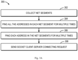
- Fig. 3A is a flowchart illustrating such a method 300 of scanning network addresses such as IP addresses.
- the system can collect net segments that are responsive to echo requests. For example, the system will scan each possible configured IP address in the range of the current subnet mask by "ping" one or more times, for example, 5 times. This phase focus on collecting the net segments with the purpose of narrowing the range of IP addresses need be scanned. For example, if the subnet mask is "255.255.0.0", in total, there are 65,334 IP addresses that need be scanned. However, perhaps all the real IP addresses of the online devices are in the range from 10.10.110.0 to 10.10.114.254. Therefore, the system will collect the net segments only from 10.10.110.XX to 10.10.114.XX.
- the system can scan each of the collected net segments for one or more rounds, for example, at most 5 rounds. More specifically during each round, the system will send asynchronously "ping" request from sub IP address 1 to 255 by using the multi-thread in each of the net segments. In order to optimize the overall time of the IP scan, the system will record the IP address as soon as it responses the "Ping" request, and this IP will not be "Pinged” again in the next round.
- the system always monitors the status of occupancy of the thread pool, if the thread pool approach to full-load, the system will be into the status of waiting until the resource of thread pool is released sufficiently.
- the system can ping each address in the collected net segments for multiple times in order to avoid the appearance of the phenomenon of device loss. For example, the system will continuously ping a single IP address by 5 times in a round, and in total 256 rounds.
- the system will send the "socket client-server" connecting requests to the IP addresses which are no response in the collected net segments by using the TCP protocol in order to discover some specific devices which disable the response of "Ping" request.
- the system can provide an entire functionality of identification for the major and interesting devices in the network of substation, including host computers, IEDs, switches and the time source devices.
- the system can support at least one of the text descriptions and the graphic presentation of devices identification information.
- the system can use one or more methods and protocols to implement the process of devices identification.
- the system can obtain the relevant information from the Substation Configuration Description (SCD) file, including technical key, IED series type, manufacturer, IP address, MAC address, Generic Object Oriented Substation Event (GOOSE) and Sample Value (SV) information.
- SCD Substation Configuration Description
- the system will query the MAC address table offered by IEEE committee to identify the device name, the manufacturer, the IP address and the MAC address.
- the system can determine the host computer identification by using the SNMP protocol. For example, the system can obtain the relevant information from the Management Information Base (MIB) in the host computers with the specific Object Identifier (OID), including mainboard configuration, Central Processing Unit (CPU) load, memory occupancy, and operation system etc. The system can obtain the manufacturer, the MAC address, the IP address information of the host computers.
- MIB Management Information Base
- OID Object Identifier
- the system can obtain the manufacturer, the MAC address, the IP address information of the host computers.
- the system can determine the switch identification by using the SNMP protocol. For example, the system can obtain the relevant information from the MIB in the switch by the specific OID, including the product name, type, manufacturer, IP address and the MAC address. Some types of switches support a common public OID, but some manufacturers only support the private OID. The system can not only support identification of all switches which support the common public OID, but also some switches which support the private OID.
- the system can determine identification information for time source devices. For the time source devices that only support the SNTP protocol, the system will send the clock synchronous request to the network of substation. If the value of time source in the response massage is not local, but is Global Positioning System (GPS) or others, the system will consider this device as a time source. For the time source devices which support the IEEE 1588 Precision Clock Synchronization Protocol, the system will capture the PTP announce packet in the network. After parsing the message, the system can obtain the MAC address of the device of time source, the type of master time source. Referring to the MAC address table offered by IEEE committee, the system can obtain the relevant information, including the manufacturer, MAC address and the IP address.
- GPS Global Positioning System
- the system can determine an inter-device connection relationship of the plurality of devices.
- Fig. 3B is a flowchart illustrating a method 350 of determining an inter-device connection relationship of the devices.
- the system can select the switches from the discovered devices list.
- the system can distinguish the switches from the discovered devices according to the proper property such as Network Bridge.
- the system can get the bridge network property information from the MIB in the switch with the OID 2.17.1.1.0.
- the common final devices e.g. like IEDs, using this OID cannot get any information. That means if the system send "Get" request with the OID 2.17.1.1.0 to a certain common final device, the response received by the system will be null. As a consequence, the switches can be selected from the discovered devices list.
- the system can obtain the AFTs (Address Forwarding Table) and relevant information.
- the system can obtain the completed AFT (Address Forwarding Table), the number of ports and the status of ports.
- the AFT contains all the destination MAC addresses, although there exits redundancy. For example, if port 1 of switch 1 is connected to port 2 of switch 2, the AFT of switch 1 contains not only the MAC address of the port 2 of switch 2, but also contains all the MAC addresses of the other ports of switch 2.
- the following steps can remove the redundant MAC addresses and obtain the accurate port-to-port connection relationship information.
- the system can discover the neighbor switches by using LLDP protocol. If the switch supports LLDP protocol, the system can obtain the connection relationship information from the MIB in the current switch by the specific OID, including IP address, MAC address and the ports which are connected between the current switch and its neighbor switches.
- the system can discover the connection relationship among switches by using RSTP protocol. If the switch does not support the LLDP protocol, the system will use the RSTP protocol to discover the connection relationship among the switch. Using the RSTP protocol, the system can obtain the STP table from the MIB in the current switch by the specific OID. Then the system can be aware of the root bridge port, the trunk ports and the blocking port. At last, the system can discover the connection relationship among the switches.
- the system can discover the connection relationship among the remaining switches based on the AFTs. For example, the system can use an AFT-based method to discover the connection relationship among the remaining switches and delete the redundant information in the Address Forwarding Table obtained from block 352.
- the system first obtains all the AFTs of the switches. Then, the system can review the status of ports and find out the ports that are connected to the other switch. The system can intersect the AFT of each switch with the AFTs of other switches one by one, and find out the switches which are directly connected.
- the system can update the information of connection relationship, delete the redundant information, and save the result.
- the system can discover the connection relationship between the switch and the other types of devices. By comparing the MAC address table of the discovered devices with the AFTs of switches, the system can discover the connection relationship between the switch and the devices of other types.
- the system can generate a layout view for the plurality of devices based on the inter-device connection relationship.
- the layout view comprising a host computer layer comprising representations of the host computers, a switch layer comprising bus lines representing the switches, and an end device layer comprising representations of the end devices. Each of the host computer layer and the end device layer is connected to the switch layer.
- Fig. 4 shows an illustrative layout view including host computers 402-406, switches 412-418, and end devices 421-452.
- the switch layer includes horizontal bus lines representing the switches 412-418 and the host computers 402-408 and the end devices 421-452 are connected to the bus lines.
- the existing layout view becomes more and more complex and unclear with the augmentation of the devices and the connection relationship.
- the three-layer layout can make the layout of the devices more clearly, even if the number of the devices substantially increases.
- an optimization method is proposed in order to reduce the connection lines as much as possible and avoid the phenomenon of the cross connection lines.
- the system can determine a first plurality of permutations of the switches that minimizes a total length of connection lines between the switches and the end devices. Then, the system can determine, from the first plurality of permutations of the switches, a second plurality of permutations of the switches that minimizes a total length of connection lines between the switches based on the first permutation of the switches. The system can then determine, from second plurality of permutations of the switches, a third permutation of the switches that minimizes a total length of connection lines between the host computers and the switches based on the second permutation of the switches. The third permutation of the switches can be used to generate the layout view.
- the first objective is to search the optimal layout which makes the total length of connection lines in the final device layer is the shortest.
- the kind of switch layout influences directly the length and the complexity of the connection lines between the final device and the switch bus line. For the reason that the amount of the final devices is the largest in the network of substation, the connection relationship in this layer is the most complex. Therefore, the first objective is to search a most optimal combination of switches so that the total length of connection lines in the final device layer is the shortest.
- the process of calculation is descripted as below.
- Step 2 Make full permutation of the switches and calculate the total length of the connection lines in the final device layer under the each kind of combination of the switches.
- CombineCnt switch represents the amount of the combinations of the switch
- Cnt switch represents the amount of switches
- TOTLength finalLayer ⁇ 1 N device Length device
- TOTLength finalLayer represents the total length of the connection lines in the final device layer
- Length device represents the length of the connection lines between the device and its corresponding switch
- N device represents the number of the devices.
- Array finalLayer represents the array of the total length of the connection lines in the final device layer with all the combinations of switches.
- TOTLength_n finalLayer represents the total length of the connection lines in the final device layer with the n combinations of switches.
- Step 3 Select the combinations of switches which make the total length of the connection lines in the final device layer is the shortest.
- the second objective is to search the optimal layout which makes the total length of connection lines in the switch layer is the shortest.
- it is desired to search the optimal layout which makes the total length of connection lines in the switch layer is the shortest.
- the detailed process of calculation is as below:
- the distance between the switch 412 and the switch 416 is two unit lengths and the distance between the switch 412 and the switch 414 is one unit length.
- Step 2 Calculate the total length of the connection line in the switch layer under each switch combination obtained from the process of achieving the 1st objective.
- TOTLength switchLayer ⁇ 1 N switch Length switch
- TOTLength switchLayer represents the total length of the connection lines in the switch layer
- Length switch represents the length of the connection lines between the device and its corresponding switch
- N switch represents the number of the devices.
- Array switchLayer TOTLength _ 1 switchLayer , TOTLength _ 2 switchLayer ... , TOTLength _ n switchLayer
- Array switchLayer represents the array of the total length of the connection lines in the switch layer with all the combinations of switches.
- TOTLength _n switchLayer represents the total length of the connection lines in the switch layer with the n combinations of switches.
- Step 3 select the combinations of switches which make the total length of the connection lines in the switch layer is the shortest.
- the third objective is to search the optimal layout which makes the total length of connection lines in the host computer layer is the shortest.
- it is desired to search the optimal layout which makes the total length of connection lines in the host computer layer is the shortest.
- the detailed process of calculation is as below:
- the distance between the host computer 404 and the switch 414 is a unit length and the distance between the host computer 406 and the switch 418 is three unit lengths.
- Step 2 Calculate the total length of the connection line in the host computer layer under each switch combinations obtained from the process of achieving the second objective.
- TOTLength PCLayer represents the total length of the connection lines in the host computer layer.
- Length PC represents the length of the connection lines between the device and its corresponding switch.
- N PC represents the number of the devices.
- Array PCLayer represents the array of the total length of the connection lines in the host computer layer with all the combinations of switches.
- TOTLength _n PCLayer represents the total length of the connection lines in the host computer layer with the n combination of switches.
- Step 3 Select the combinations of switches which make the total length of the connection lines in the host computer layer is the shortest. In fact, two most optimal combinations of switches can be obtained.
- the 2 combinations are inverse symmetrically, for example, the first combination is switch 1, switch 3, switch 4, switch 2; the second one is switch 2, switch 4, switch 3, switch 1.
- any of the combination can be as the result.
- the combination whose the first switch has the more final devices can be selected as the final optimal result.
- the time-consuming of the full permutation method will augment exponentially with the augmentation of the number of the elements.
- the test indicates that the time-consuming of the full permutation is approximately 0.7 second if the number of switches is 7, but this value augments to 4 hours when the number of switches is 10.
- the switches can be separated into two groups when the number of switches is beyond 7.
- Each group is made the full permutation and is applied the optimization method above. Then, two groups of the optimal combinations of switches can be obtained. Then, the full permutation can be applied to the two groups of the optimal combinations, and the most optimal combination of switches can be obtained.
- the maximal time consumed for 14 switches is about 4 seconds. If the number of the switches further increases, the switches can be separated into more than two groups.
- connection lines of the specific IEDs may traverse the other IEDs. As shown in Fig. 5 , a connection line of the IED 522 traverses the IED 532, and a connection line of the IED 523 traverses the IEDs 533 and 543. This illustration may cause confusion and difficulties for viewers.
- connection line for a first end device traverses at least one of other devices
- moving the representation of the first end device along the bus line such that the connection line does not traverse any of other devices.
- a method named "virtual lattice" is proposed to regular the position of the final device so that the generated final optimal layout can avoid thoroughly the situation mentioned above.
- Step 1 Generate a virtual lattice which can contain completely the zone of the final device layer, as shown Fig. 6 .
- the virtual lattice can be generated in the memory and not displayed on the interface.
- the size of each cell is the same and can contain completely the device and/or the connection line.
- Step 2 If a certain cell is filled with the device or the connection line, this cell will be noted with True. If the cell is null, it will be noted with False.
- Step 3 Move horizontally the objective device to the right. Each time, move by one cell, and then judge the status of the current cell which the objective device is in and the status of the cells which are traversed by the connection lines of the objective device, are noted with True or False. If all these status are False, the process of movement will stop, and the objective device is fixed at the best position where no other device is traversed by the connection lines of the objective device. If not, continue to move the objective device to the next cell, and repeat the judgment above until find out the best position.
- Step 4 If the objective device has been moved at the border of the current view and still there is no suitable position, the view will add automatically a new column which all the cells of this column are null, and simultaneously, the "virtual lattice" will add automatically a new null column. Because the new added column is null, it can adapt the objective device, as shown in Fig. 7 . For example, the devices 522 and 523 are moved to the new added columns.
- the system can identify the PC, switch, time source and IEDs.
- the IP address can serve as the label of devices.
- An icon of the device may be also displayed, such as a picture of its type.
- the identification and/or connectivity information can also be shown on the interface, or can be shown in response to an operation on the interface. In this way, the display can be informative and indicative to the users.
- the present invention may be a system, a method, and/or a computer program product at any possible technical detail level of integration
- the computer program product may include a computer readable storage medium (or media) having computer readable program instructions thereon for causing a processor to carry out aspects of the present invention
- the computer readable storage medium can be a tangible device that can retain and store instructions for use by an instruction execution device.
- the computer readable storage medium may be, for example, but is not limited to, an electronic storage device, a magnetic storage device, an optical storage device, an electromagnetic storage device, a semiconductor storage device, or any suitable combination of the foregoing.
- a non-exhaustive list of more specific examples of the computer readable storage medium includes the following: a portable computer diskette, a hard disk, a random access memory (RAM), a read-only memory (ROM), an erasable programmable read-only memory (EPROM or Flash memory), a static random access memory (SRAM), a portable compact disc read-only memory (CD-ROM), a digital versatile disk (DVD), a memory stick, a floppy disk, a mechanically encoded device such as punch-cards or raised structures in a groove having instructions recorded thereon, and any suitable combination of the foregoing.
- RAM random access memory
- ROM read-only memory
- EPROM or Flash memory erasable programmable read-only memory
- SRAM static random access memory
- CD-ROM compact disc read-only memory
- DVD digital versatile disk
- memory stick a floppy disk
- a mechanically encoded device such as punch-cards or raised structures in a groove having instructions recorded thereon
- a computer readable storage medium is not to be construed as being transitory signals per se, such as radio waves or other freely propagating electromagnetic waves, electromagnetic waves propagating through a waveguide or other transmission media (e.g., light pulses passing through a fiber-optic cable), or electrical signals transmitted through a wire.
- Computer readable program instructions described herein can be downloaded to respective computing/processing devices from a computer readable storage medium or to an external computer or external storage device via a network, for example, the Internet, a local area network, a wide area network and/or a wireless network.
- the network may comprise copper transmission cables, optical transmission fibers, wireless transmission, routers, firewalls, switches, gateway computers and/or edge servers.
- a network adapter card or network interface in each computing/processing device receives computer readable program instructions from the network and forwards the computer readable program instructions for storage in a computer readable storage medium within the respective computing/processing device.
- Computer readable program instructions for carrying out operations of the present invention may be assembler instructions, instruction-set-architecture (ISA) instructions, machine instructions, machine dependent instructions, microcode, firmware instructions, state-setting data, configuration data for integrated circuitry, or either source code or object code written in any combination of one or more programming languages, including an object oriented programming language such as Smalltalk, C++, or the like, and procedural programming languages, such as the "C" programming language or similar programming languages.
- the computer readable program instructions may execute entirely on the user's computer, partly on the user's computer, as a stand-alone software package, partly on the user's computer and partly on a remote computer or entirely on the remote computer or server.
- the remote computer may be connected to the user's computer through any type of network, including a local area network (LAN) or a wide area network (WAN), or the connection may be made to an external computer (for example, through the Internet using an Internet Service Provider).
- electronic circuitry including, for example, programmable logic circuitry, field-programmable gate arrays (FPGA), or programmable logic arrays (PLA) may execute the computer readable program instructions by utilizing state information of the computer readable program instructions to personalize the electronic circuitry, in order to perform aspects of the present invention.
- These computer readable program instructions may be provided to a processor of a general purpose computer, special purpose computer, or other programmable data processing apparatus to produce a machine, such that the instructions, which execute via the processor of the computer or other programmable data processing apparatus, create means for implementing the functions/acts specified in the flowchart and/or block diagram block or blocks.
- These computer readable program instructions may also be stored in a computer readable storage medium that can direct a computer, a programmable data processing apparatus, and/or other devices to function in a particular manner, such that the computer readable storage medium having instructions stored therein comprises an article of manufacture including instructions which implement aspects of the function/act specified in the flowchart and/or block diagram block or blocks.
- the computer readable program instructions may also be loaded onto a computer, other programmable data processing apparatus, or other device to cause a series of operational steps to be performed on the computer, other programmable apparatus or other device to produce a computer implemented process, such that the instructions which execute on the computer, other programmable apparatus, or other device implement the functions/acts specified in the flowchart and/or block diagram block or blocks.
- each block in the flowchart or block diagrams may represent a module, segment, or portion of instructions, which comprises one or more executable instructions for implementing the specified logical function(s).
- each block of the block diagrams and/or flowchart illustration, and combinations of blocks in the block diagrams and/or flowchart illustration can be implemented by special purpose hardware-based systems that perform the specified functions or acts or carry out combinations of special purpose hardware and computer instructions.
Landscapes
- Engineering & Computer Science (AREA)
- Computer Networks & Wireless Communication (AREA)
- Signal Processing (AREA)
- Human Computer Interaction (AREA)
- Physics & Mathematics (AREA)
- General Physics & Mathematics (AREA)
- Automation & Control Theory (AREA)
- Health & Medical Sciences (AREA)
- Cardiology (AREA)
- General Health & Medical Sciences (AREA)
- Data Exchanges In Wide-Area Networks (AREA)
Claims (12)
- Verfahren, umfassend:Bestimmen (202) einer Vielzahl von Geräten in einem vernetzten Zustand in einem Unterstationssystem, wobei die Vielzahl von Geräten Hostcomputer, Schalter und Endgeräte umfasst;Bestimmen (204) einer geräteübergreifenden Verbindungsbeziehung der Vielzahl von Geräten; undErzeugen (206) einer Layout-Ansicht für die Vielzahl von Geräten auf der Grundlage der geräteübergreifenden Verbindungsbeziehung wobei die Layout-Ansicht eine Hostcomputerschicht mit Darstellungen der Hostcomputer, eine Schalterschicht mit Busleitungen, die die Schalter darstellen, und eine Endgeräteschicht mit Darstellungen der Endgeräte umfasst, wobei sowohl die Hostcomputerschicht als auch die Endgeräteschicht mit der Schalterschicht verbunden sind;und wobei das Bestimmen der Vielzahl von Geräten umfasst:Senden einer ersten Echoanfrage an jede Netzwerkadresse in dem Unterstationssystem;als Reaktion auf den Empfang einer ersten Antwort auf die erste Echoanfrage von einer ersten Vorrichtung, Senden einer zweiten Echoanfrage an jede Netzwerkadresse in einem Netzwerksegment, das das erste Gerät umfasst; undals Reaktion auf den Empfang einer zweiten Antwort auf die zweite Echoanfrage von einem zweiten Gerät in dem Netzwerksegment, Bestimmen des zweiten Geräts als eines der Vielzahl von Geräten;und wobei das Bestimmen der Vielzahl von Geräten ferner umfasst:als Reaktion auf das Ausbleiben des Empfangs der zweiten Antwort auf die zweite Echoanfrage von einer Netzwerkadresse in dem Netzwerksegment, Senden einer Socket-Client-Server-Verbindungsanfrage an die Netzwerkadresse in dem Netzwerksegment; undals Reaktion auf den Empfang einer dritten Antwort auf die Socket-Client-Server-Verbindungsanfrage von einem dritten Gerät, Bestimmen des dritten Geräts als eines der Vielzahl von Geräten.
- Verfahren nach Anspruch 1, wobei die Endgeräte mindestens ein IED (Intelligent Electronic Device) und/oder einen Zeitgeber umfassen.
- Verfahren nach Anspruch 1, ferner umfassend:Erhalten von Identifikationsinformationen für die Vielzahl von Geräten; undwobei die Layout-Ansicht eine Darstellung der Identifikationsinformationen umfasst.
- Verfahren nach Anspruch 3, wobei die Endgeräte ein IED (Intelligent Electronic Device) und ein Zeitgeber umfassen, und wobei das Erhalten der Identifikationsinformationen umfasst:Bestimmen der Identifikationsinformationen für das IED auf der Grundlage von einer SCD-(Substation-Configuration-Description)-Datei und/oder einer IEEE-MAC-(Medium-Access-Control)-Adresstabelle; undBestimmen der Identifikationsinformationen für den Zeitgeber basierend auf mindestens einem von einem SNTP-(Simple-Network-Time Protocol)-Protokoll und einem IEEE 1588-Protokoll.
- Verfahren nach Anspruch 3, wobei das Erhalten der Identifikationsinformationen umfasst:
Bestimmen der Identifikationsinformationen für die Hostcomputer und Schalter basierend auf einem SNMP-(Simple-Network-Management-Protocol)-Protokoll. - Verfahren nach Anspruch 1, wobei das Bestimmen der geräteübergreifenden Verbindungsbeziehung umfasst:Bestimmen einer ersten Verbindungsbeziehung zwischen den Schaltern in der Vielzahl von Geräten als Teil der geräteübergreifenden Verbindungsbeziehung; undBestimmen, basierend auf einer IEEE-MAC-(Medium Access Control)-Adresstabelle und AFTs (Address Forwarding Tables) für die Schalter, einer zweiten Verbindungsbeziehung zwischen den Schaltern und den verbleibenden Geräten, die in der Vielzahl von Geräten umfasst sind, als weiterer Teil der geräteübergreifenden Verbindungsbeziehung.
- Verfahren nach Anspruch 6, wobei das Bestimmen der ersten Verbindungsbeziehung zwischen den Schaltern umfasst:Ermitteln eines oder mehrerer benachbarter Schalter aus den Schaltern auf der Grundlage von mindestens einem Ermittlungsprotokoll und einem RSTP-(Rapid Spanning Tree Protocol)-Protokoll;Erhalten der AFTs für die Schalter auf der Grundlage eines SNMP-(Simple Network Management Protocol)-Protokolls; undErmitteln einer Verbindungsbeziehung zwischen anderen Schaltern auf der Grundlage der AFTs.
- Verfahren nach Anspruch 1, wobei das Erzeugen der Layout-Ansicht umfasst:Bestimmen einer ersten Vielzahl von Permutationen der Schalter, die eine Gesamtlänge von Verbindungsleitungen zwischen den Schaltern und den Endgeräten minimiert;Bestimmen einer zweiten Vielzahl von Permutationen der Schalter aus der ersten Vielzahl von Permutationen der Schalter, die eine Gesamtlänge von Verbindungsleitungen zwischen den Schaltern basierend auf der ersten Permutation der Schalter minimiert; undBestimmen einer dritten Permutation der Schalter aus der zweiten Vielzahl von Permutationen der Schalter, die eine Gesamtlänge von Verbindungsleitungen zwischen den Hostcomputern und den Schaltern basierend auf der zweiten Permutation der Schalter minimiert; undErzeugen der Layout-Ansicht auf der Grundlage der dritten Permutation der Schalter.
- Verfahren nach Anspruch 1, wobei das Erzeugen der Layout-Ansicht umfasst:
als Reaktion darauf, dass eine Verbindungsleitung für ein erstes Endgerät der Endgeräte durch mindestens eines der anderen Geräte verläuft, Bewegen der Darstellung des ersten Endgeräts entlang der Busleitung, so dass die Verbindungsleitung durch keines der anderen Geräte verläuft. - Rechenvorrichtung, umfassend:einen Prozessor; undein computerlesbares Speichermedium, das Anweisungen speichert, die, wenn sie durch den Prozessor ausgeführt werden, den Prozessor veranlassen, das Verfahren nach einem der Ansprüche 1 bis 9 auszuführen.
- Unterstation, umfassend:Host-Computer;an die Host-Computer gekoppelte Schalter;an die Schalter gekoppelte Endgeräte; unddie Rechenvorrichtung nach Anspruch 10.
- Computerlesbares Speichermedium, das Anweisungen speichert, die bei Ausführung durch eine Rechenvorrichtung bewirken, dass die Rechenvorrichtung das Verfahren nach einem der Ansprüche 1 bis 9 ausführt.
Applications Claiming Priority (1)
| Application Number | Priority Date | Filing Date | Title |
|---|---|---|---|
| PCT/CN2019/087952 WO2020232667A1 (en) | 2019-05-22 | 2019-05-22 | Network topology discovery in substation |
Publications (4)
| Publication Number | Publication Date |
|---|---|
| EP3973667A1 EP3973667A1 (de) | 2022-03-30 |
| EP3973667A4 EP3973667A4 (de) | 2023-01-11 |
| EP3973667C0 EP3973667C0 (de) | 2025-05-14 |
| EP3973667B1 true EP3973667B1 (de) | 2025-05-14 |
Family
ID=73459410
Family Applications (1)
| Application Number | Title | Priority Date | Filing Date |
|---|---|---|---|
| EP19930033.6A Active EP3973667B1 (de) | 2019-05-22 | 2019-05-22 | Netzwerktopologiebestimmung in einer unterstation |
Country Status (4)
| Country | Link |
|---|---|
| US (1) | US11496369B2 (de) |
| EP (1) | EP3973667B1 (de) |
| CN (1) | CN113273135B (de) |
| WO (1) | WO2020232667A1 (de) |
Families Citing this family (4)
| Publication number | Priority date | Publication date | Assignee | Title |
|---|---|---|---|---|
| CN115589364A (zh) * | 2021-07-06 | 2023-01-10 | 华为技术有限公司 | 一种通信方法、系统和装置 |
| TWI821741B (zh) * | 2021-09-07 | 2023-11-11 | 四零四科技股份有限公司 | 處理資料流的裝置及方法 |
| CN114244758B (zh) * | 2021-12-13 | 2024-06-25 | 武汉斗鱼鱼乐网络科技有限公司 | 安卓平台的网络诊断方法、存储介质、电子设备及系统 |
| CN116827801B (zh) * | 2023-08-25 | 2023-12-15 | 武汉吧哒科技股份有限公司 | 网络拓扑构建方法、装置、计算机设备及可读存储介质 |
Family Cites Families (14)
| Publication number | Priority date | Publication date | Assignee | Title |
|---|---|---|---|---|
| US6504841B1 (en) * | 1998-04-06 | 2003-01-07 | Lockheed Martin Corporation | Three-dimensional interconnection geometries for multi-stage switching networks using flexible ribbon cable connection between multiple planes |
| US20030154306A1 (en) * | 2002-02-11 | 2003-08-14 | Perry Stephen Hastings | System and method to proxy inbound connections to privately addressed hosts |
| US7493562B2 (en) * | 2003-06-27 | 2009-02-17 | Computer Associates Think, Inc. | System and method for bridge port administration |
| WO2005024567A2 (en) * | 2003-08-18 | 2005-03-17 | Spearman Anthony C | Network communication security system, monitoring system and methods |
| US20120105249A1 (en) * | 2008-09-09 | 2012-05-03 | T-Systems International Gmbh | Method and Distributed System for Detecting and Managing Data from a Plurality of Measuring Devices |
| US9516451B2 (en) * | 2012-04-10 | 2016-12-06 | Mcafee, Inc. | Opportunistic system scanning |
| GB2502349B (en) * | 2012-05-25 | 2019-03-06 | Nidec Control Techniques Ltd | Method and system for communicating between devices |
| US20140282021A1 (en) * | 2013-03-15 | 2014-09-18 | Schweitzer Engineering Laboratories, Inc. | Visualization of Communication Between Devices in an Electric Power System |
| CN105264943A (zh) * | 2013-11-29 | 2016-01-20 | 华为技术有限公司 | 维护管理方法、设备及设备维护系统 |
| CN103716189B (zh) * | 2013-12-24 | 2017-01-04 | 深圳市共进电子股份有限公司 | 一种局域网终端网关设备配置管理方法 |
| CN103746840B (zh) * | 2013-12-30 | 2017-05-17 | 迈普通信技术股份有限公司 | 网络设备软件版本信息自动核对方法和系统 |
| CN103762591B (zh) * | 2014-01-16 | 2016-04-20 | 国家电网公司 | 一种配电网拓扑布图方法 |
| CN103856579B (zh) * | 2014-03-03 | 2017-01-25 | 国家电网公司 | 基于mac地址匹配的智能变电站网络设备拓扑动态识别方法 |
| CN108429637B (zh) * | 2018-02-05 | 2021-05-07 | 国电南瑞科技股份有限公司 | 一种智能变电站过程层网络拓扑动态探测系统及方法 |
-
2019
- 2019-05-22 US US17/415,185 patent/US11496369B2/en active Active
- 2019-05-22 WO PCT/CN2019/087952 patent/WO2020232667A1/en not_active Ceased
- 2019-05-22 EP EP19930033.6A patent/EP3973667B1/de active Active
- 2019-05-22 CN CN201980087452.9A patent/CN113273135B/zh active Active
Also Published As
| Publication number | Publication date |
|---|---|
| US11496369B2 (en) | 2022-11-08 |
| US20220060383A1 (en) | 2022-02-24 |
| WO2020232667A1 (en) | 2020-11-26 |
| EP3973667C0 (de) | 2025-05-14 |
| CN113273135A (zh) | 2021-08-17 |
| EP3973667A1 (de) | 2022-03-30 |
| EP3973667A4 (de) | 2023-01-11 |
| CN113273135B (zh) | 2023-08-01 |
Similar Documents
| Publication | Publication Date | Title |
|---|---|---|
| EP3973667B1 (de) | Netzwerktopologiebestimmung in einer unterstation | |
| CN110661669B (zh) | 一种基于icmp、tcp、udp协议的网络设备的网络拓扑自动发现方法 | |
| JP7108674B2 (ja) | 故障根本原因決定方法及び装置並びにコンピュータ記憶媒体 | |
| CN110247784B (zh) | 确定网络拓扑结构的方法和装置 | |
| KR102014433B1 (ko) | 미들웨어 머신 환경에서 기능이 저하된 팻-트리들을 디스커버링 및 라우팅하는 것을 지원하는 시스템 및 방법 | |
| CN114915561B (zh) | 网络拓扑图生成方法和装置 | |
| WO2020135575A1 (zh) | 一种获取网络拓扑的系统、方法和服务器 | |
| EP3304822A1 (de) | Verfahren und vorrichtung zur gruppierung von features in klassen mit ausgewählten klassengrenzen zur verwendung in der anomaliedetektion | |
| US20150074260A1 (en) | Auto discovery and topology rendering in substation networks | |
| CN109067569B (zh) | 一种工控网络拓扑结构可视化方法 | |
| CN107666493B (zh) | 一种数据库配置方法及其设备 | |
| CN113364681B (zh) | 网络路径确定方法、装置、电子设备、介质和程序产品 | |
| EP3857823A1 (de) | Automatische klassifikation von netzwerkvorrichtungen in einem netzwerk | |
| WO2019085975A1 (zh) | 一种网络拓扑显示方法及网络管理设备 | |
| CN116545861A (zh) | 网络拓扑图生成方法、装置和设备 | |
| CN102571416B (zh) | 一种虚拟机位置定位方法和装置 | |
| CN111988439B (zh) | 一种arp请求抑制系统、方法、设备及存储介质 | |
| KR20210147966A (ko) | 네트워크 토폴로지 발견 방법, 디바이스, 및 시스템 | |
| US20130042020A1 (en) | Quick Network Path Discovery | |
| CN109412851B (zh) | 链路层路径检测方法、装置及系统 | |
| US20040158780A1 (en) | Method and system for presenting neighbors of a device in a network via a graphical user interface | |
| CN104219100A (zh) | 一种信息采集方法和装置 | |
| JP5686188B2 (ja) | 経路探索プログラムおよび情報処理装置 | |
| CN119254753A (zh) | 智能计算中心的算力任务网络接入方法及相关设备 | |
| CN116248626A (zh) | 一种真实源地址通信方法、装置、电子设备和存储介质 |
Legal Events
| Date | Code | Title | Description |
|---|---|---|---|
| STAA | Information on the status of an ep patent application or granted ep patent |
Free format text: STATUS: THE INTERNATIONAL PUBLICATION HAS BEEN MADE |
|
| PUAI | Public reference made under article 153(3) epc to a published international application that has entered the european phase |
Free format text: ORIGINAL CODE: 0009012 |
|
| STAA | Information on the status of an ep patent application or granted ep patent |
Free format text: STATUS: REQUEST FOR EXAMINATION WAS MADE |
|
| 17P | Request for examination filed |
Effective date: 20210615 |
|
| AK | Designated contracting states |
Kind code of ref document: A1 Designated state(s): AL AT BE BG CH CY CZ DE DK EE ES FI FR GB GR HR HU IE IS IT LI LT LU LV MC MK MT NL NO PL PT RO RS SE SI SK SM TR |
|
| DAV | Request for validation of the european patent (deleted) | ||
| DAX | Request for extension of the european patent (deleted) | ||
| REG | Reference to a national code |
Ref country code: DE Ref legal event code: R079 Ipc: H04L0041120000 Ref country code: DE Ref legal event code: R079 Ref document number: 602019070114 Country of ref document: DE Free format text: PREVIOUS MAIN CLASS: H04L0012240000 Ipc: H04L0041120000 |
|
| A4 | Supplementary search report drawn up and despatched |
Effective date: 20221209 |
|
| RIC1 | Information provided on ipc code assigned before grant |
Ipc: H04L 43/10 20220101ALI20221205BHEP Ipc: H04L 41/22 20220101ALI20221205BHEP Ipc: H04L 41/12 20220101AFI20221205BHEP |
|
| STAA | Information on the status of an ep patent application or granted ep patent |
Free format text: STATUS: EXAMINATION IS IN PROGRESS |
|
| 17Q | First examination report despatched |
Effective date: 20230718 |
|
| GRAP | Despatch of communication of intention to grant a patent |
Free format text: ORIGINAL CODE: EPIDOSNIGR1 |
|
| STAA | Information on the status of an ep patent application or granted ep patent |
Free format text: STATUS: GRANT OF PATENT IS INTENDED |
|
| INTG | Intention to grant announced |
Effective date: 20241216 |
|
| GRAS | Grant fee paid |
Free format text: ORIGINAL CODE: EPIDOSNIGR3 |
|
| GRAA | (expected) grant |
Free format text: ORIGINAL CODE: 0009210 |
|
| STAA | Information on the status of an ep patent application or granted ep patent |
Free format text: STATUS: THE PATENT HAS BEEN GRANTED |
|
| AK | Designated contracting states |
Kind code of ref document: B1 Designated state(s): AL AT BE BG CH CY CZ DE DK EE ES FI FR GB GR HR HU IE IS IT LI LT LU LV MC MK MT NL NO PL PT RO RS SE SI SK SM TR |
|
| REG | Reference to a national code |
Ref country code: GB Ref legal event code: FG4D |
|
| REG | Reference to a national code |
Ref country code: CH Ref legal event code: EP |
|
| REG | Reference to a national code |
Ref country code: DE Ref legal event code: R096 Ref document number: 602019070114 Country of ref document: DE |
|
| REG | Reference to a national code |
Ref country code: IE Ref legal event code: FG4D |
|
| U01 | Request for unitary effect filed |
Effective date: 20250613 |
|
| U07 | Unitary effect registered |
Designated state(s): AT BE BG DE DK EE FI FR IT LT LU LV MT NL PT RO SE SI Effective date: 20250624 |
|
| U20 | Renewal fee for the european patent with unitary effect paid |
Year of fee payment: 7 Effective date: 20250728 |
|
| PG25 | Lapsed in a contracting state [announced via postgrant information from national office to epo] |
Ref country code: ES Free format text: LAPSE BECAUSE OF FAILURE TO SUBMIT A TRANSLATION OF THE DESCRIPTION OR TO PAY THE FEE WITHIN THE PRESCRIBED TIME-LIMIT Effective date: 20250514 |
|
| PG25 | Lapsed in a contracting state [announced via postgrant information from national office to epo] |
Ref country code: NO Free format text: LAPSE BECAUSE OF FAILURE TO SUBMIT A TRANSLATION OF THE DESCRIPTION OR TO PAY THE FEE WITHIN THE PRESCRIBED TIME-LIMIT Effective date: 20250814 Ref country code: GR Free format text: LAPSE BECAUSE OF FAILURE TO SUBMIT A TRANSLATION OF THE DESCRIPTION OR TO PAY THE FEE WITHIN THE PRESCRIBED TIME-LIMIT Effective date: 20250815 |
|
| PG25 | Lapsed in a contracting state [announced via postgrant information from national office to epo] |
Ref country code: PL Free format text: LAPSE BECAUSE OF FAILURE TO SUBMIT A TRANSLATION OF THE DESCRIPTION OR TO PAY THE FEE WITHIN THE PRESCRIBED TIME-LIMIT Effective date: 20250514 |
|
| PG25 | Lapsed in a contracting state [announced via postgrant information from national office to epo] |
Ref country code: HR Free format text: LAPSE BECAUSE OF FAILURE TO SUBMIT A TRANSLATION OF THE DESCRIPTION OR TO PAY THE FEE WITHIN THE PRESCRIBED TIME-LIMIT Effective date: 20250514 |
|
| PG25 | Lapsed in a contracting state [announced via postgrant information from national office to epo] |
Ref country code: RS Free format text: LAPSE BECAUSE OF FAILURE TO SUBMIT A TRANSLATION OF THE DESCRIPTION OR TO PAY THE FEE WITHIN THE PRESCRIBED TIME-LIMIT Effective date: 20250814 |
|
| PG25 | Lapsed in a contracting state [announced via postgrant information from national office to epo] |
Ref country code: IS Free format text: LAPSE BECAUSE OF FAILURE TO SUBMIT A TRANSLATION OF THE DESCRIPTION OR TO PAY THE FEE WITHIN THE PRESCRIBED TIME-LIMIT Effective date: 20250914 |
|
| REG | Reference to a national code |
Ref country code: CH Ref legal event code: H13 Free format text: ST27 STATUS EVENT CODE: U-0-0-H10-H13 (AS PROVIDED BY THE NATIONAL OFFICE) Effective date: 20251223 |
|
| PG25 | Lapsed in a contracting state [announced via postgrant information from national office to epo] |
Ref country code: SM Free format text: LAPSE BECAUSE OF FAILURE TO SUBMIT A TRANSLATION OF THE DESCRIPTION OR TO PAY THE FEE WITHIN THE PRESCRIBED TIME-LIMIT Effective date: 20250514 |
|
| PG25 | Lapsed in a contracting state [announced via postgrant information from national office to epo] |
Ref country code: CH Free format text: LAPSE BECAUSE OF NON-PAYMENT OF DUE FEES Effective date: 20250531 |
|
| PG25 | Lapsed in a contracting state [announced via postgrant information from national office to epo] |
Ref country code: CZ Free format text: LAPSE BECAUSE OF FAILURE TO SUBMIT A TRANSLATION OF THE DESCRIPTION OR TO PAY THE FEE WITHIN THE PRESCRIBED TIME-LIMIT Effective date: 20250514 |
|
| PG25 | Lapsed in a contracting state [announced via postgrant information from national office to epo] |
Ref country code: SK Free format text: LAPSE BECAUSE OF FAILURE TO SUBMIT A TRANSLATION OF THE DESCRIPTION OR TO PAY THE FEE WITHIN THE PRESCRIBED TIME-LIMIT Effective date: 20250514 |