EP3973640B1 - Verfahren und vorrichtung zur auslösung eines mehrstrahlberichts - Google Patents
Verfahren und vorrichtung zur auslösung eines mehrstrahlberichts Download PDFInfo
- Publication number
- EP3973640B1 EP3973640B1 EP20841177.7A EP20841177A EP3973640B1 EP 3973640 B1 EP3973640 B1 EP 3973640B1 EP 20841177 A EP20841177 A EP 20841177A EP 3973640 B1 EP3973640 B1 EP 3973640B1
- Authority
- EP
- European Patent Office
- Prior art keywords
- reporting
- resource
- csi
- gnb
- resources
- Prior art date
- Legal status (The legal status is an assumption and is not a legal conclusion. Google has not performed a legal analysis and makes no representation as to the accuracy of the status listed.)
- Active
Links
Images


Classifications
-
- H—ELECTRICITY
- H04—ELECTRIC COMMUNICATION TECHNIQUE
- H04B—TRANSMISSION
- H04B17/00—Monitoring; Testing
- H04B17/30—Monitoring; Testing of propagation channels
- H04B17/309—Measuring or estimating channel quality parameters
- H04B17/318—Received signal strength
- H04B17/327—Received signal code power [RSCP]
-
- H—ELECTRICITY
- H04—ELECTRIC COMMUNICATION TECHNIQUE
- H04B—TRANSMISSION
- H04B17/00—Monitoring; Testing
- H04B17/30—Monitoring; Testing of propagation channels
- H04B17/309—Measuring or estimating channel quality parameters
- H04B17/336—Signal-to-interference ratio [SIR] or carrier-to-interference ratio [CIR]
-
- H—ELECTRICITY
- H04—ELECTRIC COMMUNICATION TECHNIQUE
- H04B—TRANSMISSION
- H04B7/00—Radio transmission systems, i.e. using radiation field
- H04B7/02—Diversity systems; Multi-antenna system, i.e. transmission or reception using multiple antennas
- H04B7/04—Diversity systems; Multi-antenna system, i.e. transmission or reception using multiple antennas using two or more spaced independent antennas
- H04B7/06—Diversity systems; Multi-antenna system, i.e. transmission or reception using multiple antennas using two or more spaced independent antennas at the transmitting station
- H04B7/0613—Diversity systems; Multi-antenna system, i.e. transmission or reception using multiple antennas using two or more spaced independent antennas at the transmitting station using simultaneous transmission
- H04B7/0615—Diversity systems; Multi-antenna system, i.e. transmission or reception using multiple antennas using two or more spaced independent antennas at the transmitting station using simultaneous transmission of weighted versions of same signal
- H04B7/0617—Diversity systems; Multi-antenna system, i.e. transmission or reception using multiple antennas using two or more spaced independent antennas at the transmitting station using simultaneous transmission of weighted versions of same signal for beam forming
-
- H—ELECTRICITY
- H04—ELECTRIC COMMUNICATION TECHNIQUE
- H04B—TRANSMISSION
- H04B7/00—Radio transmission systems, i.e. using radiation field
- H04B7/02—Diversity systems; Multi-antenna system, i.e. transmission or reception using multiple antennas
- H04B7/04—Diversity systems; Multi-antenna system, i.e. transmission or reception using multiple antennas using two or more spaced independent antennas
- H04B7/06—Diversity systems; Multi-antenna system, i.e. transmission or reception using multiple antennas using two or more spaced independent antennas at the transmitting station
- H04B7/0613—Diversity systems; Multi-antenna system, i.e. transmission or reception using multiple antennas using two or more spaced independent antennas at the transmitting station using simultaneous transmission
- H04B7/0615—Diversity systems; Multi-antenna system, i.e. transmission or reception using multiple antennas using two or more spaced independent antennas at the transmitting station using simultaneous transmission of weighted versions of same signal
- H04B7/0619—Diversity systems; Multi-antenna system, i.e. transmission or reception using multiple antennas using two or more spaced independent antennas at the transmitting station using simultaneous transmission of weighted versions of same signal using feedback from receiving side
- H04B7/0621—Feedback content
- H04B7/0626—Channel coefficients, e.g. channel state information [CSI]
-
- H—ELECTRICITY
- H04—ELECTRIC COMMUNICATION TECHNIQUE
- H04B—TRANSMISSION
- H04B7/00—Radio transmission systems, i.e. using radiation field
- H04B7/02—Diversity systems; Multi-antenna system, i.e. transmission or reception using multiple antennas
- H04B7/04—Diversity systems; Multi-antenna system, i.e. transmission or reception using multiple antennas using two or more spaced independent antennas
- H04B7/06—Diversity systems; Multi-antenna system, i.e. transmission or reception using multiple antennas using two or more spaced independent antennas at the transmitting station
- H04B7/0686—Hybrid systems, i.e. switching and simultaneous transmission
- H04B7/0695—Hybrid systems, i.e. switching and simultaneous transmission using beam selection
- H04B7/06952—Selecting one or more beams from a plurality of beams, e.g. beam training, management or sweeping
- H04B7/0696—Determining beam pairs
-
- H—ELECTRICITY
- H04—ELECTRIC COMMUNICATION TECHNIQUE
- H04L—TRANSMISSION OF DIGITAL INFORMATION, e.g. TELEGRAPHIC COMMUNICATION
- H04L5/00—Arrangements affording multiple use of the transmission path
- H04L5/003—Arrangements for allocating sub-channels of the transmission path
- H04L5/0048—Allocation of pilot signals, i.e. of signals known to the receiver
- H04L5/0051—Allocation of pilot signals, i.e. of signals known to the receiver of dedicated pilots, i.e. pilots destined for a single user or terminal
-
- H—ELECTRICITY
- H04—ELECTRIC COMMUNICATION TECHNIQUE
- H04W—WIRELESS COMMUNICATION NETWORKS
- H04W24/00—Supervisory, monitoring or testing arrangements
- H04W24/10—Scheduling measurement reports ; Arrangements for measurement reports
-
- H—ELECTRICITY
- H04—ELECTRIC COMMUNICATION TECHNIQUE
- H04W—WIRELESS COMMUNICATION NETWORKS
- H04W72/00—Local resource management
- H04W72/20—Control channels or signalling for resource management
- H04W72/23—Control channels or signalling for resource management in the downlink direction of a wireless link, i.e. towards a terminal
Definitions
- the present disclosure relates generally to methods for wireless communication systems and, more specifically, reporting for multi-beam system.
- the 5G or pre-5G communication system is also called a ⁇ beyond 4G network' or a ⁇ post long term evolution (LTE) system'.
- the 5G communication system is considered to be implemented in higher frequency (mmWave) bands, e.g., 60 GHz bands, so as to accomplish higher data rates.
- mmWave e.g. 60 GHz bands
- beamforming massive multiple-input multiple-output (MIMO), full dimensional MIMO (FD-MIMO), array antenna, analog beamforming, and large scale antenna techniques are discussed with respect to 5G communication systems.
- RANs cloud radio access networks
- D2D device-to-device
- SWSC sliding window superposition coding
- ACM advanced coding modulation
- FBMC filter bank multi carrier
- NOMA non-orthogonal multiple access
- SCMA sparse code multiple access
- the Internet which is a human centered connectivity network where humans generate and consume information
- IoT Internet of things
- IoE Internet of everything
- technologies such as as As technonologyed connectivity network where humans generate and consume information
- IoT Internet of things
- ud server has emeIoT implementation
- M2M machine-to-machine
- MTC machine type communication
- IoT Internet technology services
- IoT may be applied to a variety of fields including smart home, smart building, smart city, smart car or connected cars, smart grid, health care, smart appliances and advanced medical services through convergence and combination between existing information technology (IT) and various industrial applications.
- IT information technology
- 5G communication systems to IoT networks.
- technologies such as a sensor network, MTC, and M2M communication may be implemented by beamforming, MIMO, and array antennas.
- Application of a cloud RAN as the above-described big data processing technology may also be considered to be as an example of convergence between the 5G technology and the IoT technology.
- XIAOMI "Enhancements on beam management", 3GPP DRAFT; R1-1813340, 3RD GENERATION PARTNERSHIP PROJECT (3GPP), MOBILE COMPETENCE CENTRE; 650, ROUTE DES LUCIOLES; F-06921 SOPHIA-ANTIPOLIS CEDEX; FRANCE, vol. RAN WG1, no. Spokane, USA; 20181112 - 20181116 2 November 2018 (2018-11-02), pages 1-4 , discloses a beam measurement procedure that starts after the RRC connection between UE and gNB and reuses the frame structure of CSI measurement and reporting configuration.
- NOKIA ET AL “On beam grouping and reporting", 3GPP DRAFT; R1-1708907, 3RD GENERATION PARTNERSHIP PROJECT (3GPP), MOBILE COMPETENCE CENTRE; 650, ROUTE DES LUCIOLES; F-06921 SOPHIA-ANTIPOLIS CEDEX; FRANCE, vol. RAN WG1, no. Hangzhou; 20170515 - 20170519 14 May 2017 (2017-05-14 ), discusses details of UE based beam grouping reporting schemes and related signalling aspects, and suggests to use MAC CE for the full scale beams reports and then update full scale beam reports with differential or partial beam reports with layer 1 control channel, i.e. PUCCH.
- PUCCH layer 1 control channel
- From US 2019/173534 A1 is known a method for uplink transmission from a user equipment including multiple transmission resources in a wireless communication system which includes selecting of PUSCH or PUCCH resources for transmission, based on the quality of a reference signal.
- Various embodiments of the present disclosure provide methods and apparatuses for beam reporting.
- the present disclosure relates to a pre-5th-Generation (5G) or 5G communication system to be provided for supporting higher data rates Beyond 4th-Generation (4G) communication system such as Long-Term Evolution (LTE).
- 5G pre-5th-Generation
- 4G 4th-Generation
- LTE Long-Term Evolution
- a user equipment (UE) according to claim 1 is provided.
- a base station (BS) according to claim 3 is provided.
- a method for operating a user equipment (UE) according to claim 4 and a method for operating a base station according to claim 6 are provided.
- Couple and its derivatives refer to any direct or indirect communication between two or more elements, whether or not those elements are in physical contact with one another.
- transmit and “communicate,” as well as derivatives thereof, encompass both direct and indirect communication.
- the term “or” is inclusive, meaning and/or.
- controller means any device, system or part thereof that controls at least one operation. Such a controller can be implemented in hardware or a combination of hardware and software and/or firmware. The functionality associated with any particular controller can be centralized or distributed, whether locally or remotely.
- phrases "at least one of,” when used with a list of items, means that different combinations of one or more of the listed items can be used, and only one item in the list can be needed.
- “at least one of: A, B, and C” includes any of the following combinations: A, B, C, A and B, A and C, B and C, and A and B and C.
- various functions described below can be implemented or supported by one or more computer programs, each of which is formed from computer readable program code and embodied in a computer readable medium.
- application and “program” refer to one or more computer programs, software components, sets of instructions, procedures, functions, objects, classes, instances, related data, or a portion thereof adapted for implementation in a suitable computer readable program code.
- computer readable program code includes any type of computer code, including source code, object code, and executable code.
- computer readable medium includes any type of medium capable of being accessed by a computer, such as read only memory (ROM), random access memory (RAM), a hard disk drive, a compact disc (CD), a digital video disc (DVD), or any other type of memory.
- ROM read only memory
- RAM random access memory
- CD compact disc
- DVD digital video disc
- a "non-transitory” computer readable medium excludes wired, wireless, optical, or other communication links that transport transitory electrical or other signals.
- a non-transitory computer readable medium includes media where data can be permanently stored and media where data can be stored and later overwritten, such as a rewritable optical disc or an erasable memory device.
- FIGURES 1 through 14 discussed below, and the various embodiments used to describe the principles of the present disclosure in this disclosure are by way of illustration only and should not be construed in any way to limit the scope of the disclosure. Those skilled in the art will understand that the principles of the present disclosure can be implemented in any suitably arranged wireless communication system.
- Wireless communication has been one of the most successful innovations in modern history.
- the demand of wireless data traffic is rapidly increasing due to the growing popularity among consumers and businesses of smart phones and other mobile data devices, such as tablets, "note pad” computers, net books, eBook readers, and machine type of devices.
- improvements in radio interface efficiency and coverage is of paramount importance.
- a mobile device or user equipment can measure the quality of the downlink channel and report this quality to a base station so that a determination can be made regarding whether or not various parameters should be adjusted during communication with the mobile device.
- Existing channel quality reporting processes in wireless communications systems do not sufficiently accommodate reporting of channel state information associated with large, two-dimensional array transmit antennas or, in general, antenna array geometry which accommodates a large number of antenna elements.
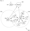
- FIGURE 1 illustrates an example wireless network 100 according to various embodiments of the present disclosure.
- the embodiment of the wireless network 100 shown in FIGURE 1 is for illustration only. Other embodiments of the wireless network 100 can be used without departing from the scope of the present disclosure.
- the wireless network 100 includes a BS 101, a BS 102, and a BS 103.
- the BS 101 communicates with the BS 102 and the BS 103.
- the BS 101 also communicates with at least one Internet Protocol (IP) network 130, such as the Internet, a proprietary IP network, or other data network.
- IP Internet Protocol
- eNB enhanced Node B
- gNB General Node B
- other well-known terms can be used instead of "gNB” or "BS,” such as “base station” or “access point.”
- gNB and BS are used in the present disclosure to refer to network infrastructure components that provide wireless access to remote terminals.
- UE user equipment
- mobile station such as a mobile telephone or smartphone
- remote terminal such as a desktop computer or vending machine
- the gNB 102 provides wireless broadband access to the network 130 for a first plurality of UEs within a coverage area 120 of the gNB 102.
- the first plurality of UEs includes a UE 111, which can be located in a small business; a UE 112, which can be located in an enterprise (E); a UE 113, which can be located in a WiFi hotspot (HS); a UE 114, which can be located in a first residence (R); a UE 115, which can be located in a second residence (R); and a UE 116, which can be a mobile device (M) like a cell phone, a wireless laptop, a wireless PDA, or the like.
- M mobile device
- the gNB 103 provides wireless broadband access to the network 130 for a second plurality of UEs within a coverage area 125 of the gNB 103.
- the second plurality of UEs includes the UE 115 and the UE 116.
- one or more of the gNBs 101-103 can communicate with each other and with the UEs 111-116 using 5G, LTE, LTE-A, WiMAX, or other advanced wireless communication techniques.
- Dotted lines show the approximate extents of the coverage areas 120 and 125, which are shown as approximately circular for the purposes of illustration and explanation only.
- the coverage areas associated with gNBs such as the coverage areas 120 and 125, can have other shapes, including irregular shapes, depending upon the configuration of the gNBs and variations in the radio environment associated with natural and man-made obstructions.
- one or more of gNB 101, gNB 102, and gNB 103 transmits beam reporting information to UEs 111-116 and configure UEs 111-116 for beam reporting as described in embodiments of the present disclosure.
- one or more of UEs 111-116 receive beam reporting information as described in embodiments of the present disclosure.
- FIGURE 1 illustrates one example of a wireless network 100
- the wireless network 100 can include any number of gNBs and any number of UEs in any suitable arrangement.
- the gNB 101 can communicate directly with any number of UEs and provide those UEs with wireless broadband access to the network 130.
- each gNB 102-103 can communicate directly with the network 130 and provide UEs with direct wireless broadband access to the network 130.
- the gNB 101, 102, and/or 103 can provide access to other or additional external networks, such as external telephone networks or other types of data networks.
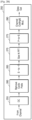
- FIGURES 2A and 2B illustrate example wireless transmit and receive paths according to the present disclosure.
- a transmit path 200 can be described as being implemented in a gNB (such as gNB 102), while a receive path 250 can be described as being implemented in a UE (such as UE 116).
- the receive path 250 can be implemented in a gNB and that the transmit path 200 can be implemented in a UE.
- the receive path 250 is configured to receive beam reporting information as described in embodiments of the present disclosure.
- the transmit path 200 includes a channel coding and modulation block 205, a serial-to-parallel (S-to-P) block 210, a size N Inverse Fast Fourier Transform (IFFT) block 215, a parallel-to-serial (P-to-S) block 220, an ⁇ add cyclic prefix' block 225, and an up-converter (UC) 230.
- S-to-P serial-to-parallel
- IFFT Inverse Fast Fourier Transform
- P-to-S parallel-to-serial
- UC up-converter
- the receive path 250 includes a down-converter (DC) 255, a ⁇ remove cyclic prefix' block 260, a serial-to-parallel (S-to-P) block 265, a size N Fast Fourier Transform (FFT) block 270, a parallel-to-serial (P-to-S) block 275, and a channel decoding and demodulation block 280.
- DC down-converter
- S-to-P serial-to-parallel
- FFT Fast Fourier Transform
- P-to-S parallel-to-serial
- the channel coding and modulation block 205 receives a set of information bits, applies coding (such as convolutional, Turbo, or low-density parity check (LDPC) coding), and modulates the input bits (such as with Quadrature Phase Shift Keying (QPSK) or Quadrature Amplitude Modulation (QAM)) to generate a sequence of frequency-domain modulation symbols.
- coding such as convolutional, Turbo, or low-density parity check (LDPC) coding
- modulates the input bits such as with Quadrature Phase Shift Keying (QPSK) or Quadrature Amplitude Modulation (QAM)
- QPSK Quadrature Phase Shift Keying
- QAM Quadrature Amplitude Modulation
- the S-to-P block 210 converts (such as de-multiplexes) the serial modulated symbols to parallel data in order to generate N parallel symbol streams, where N is the IFFT/FFT size used in the gNB 102 and the UE 116.
- the size N IFFT block 215 performs an IFFT operation on the N parallel symbol streams to generate time-domain output signals.
- the P-to-S block 220 converts (such as multiplexes) the parallel time-domain output symbols from the size N IFFT block 215 in order to generate a serial time-domain signal.
- the ⁇ add cyclic prefix' block 225 inserts a cyclic prefix to the time-domain signal.
- the UC 230 modulates (such as up-converts) the output of the ⁇ add cyclic prefix' block 225 to an RF frequency for transmission via a wireless channel.
- the signal can also be filtered at baseband before conversion to the RF frequency.
- a transmitted RF signal from the gNB 102 arrives at the UE 116 after passing through the wireless channel, and reverse operations to those at the gNB 102 are performed at the UE 116.
- the DC 255 down-converts the received signal to a baseband frequency
- the ⁇ remove cyclic prefix' block 260 removes the cyclic prefix to generate a serial time-domain baseband signal.
- the serial-to-parallel block 265 converts the time-domain baseband signal to parallel time domain signals.
- the size N FFT block 270 performs an FFT algorithm to generate N parallel frequency-domain signals.
- the parallel-to-serial block 275 converts the parallel frequency-domain signals to a sequence of modulated data symbols.
- the channel decoding and demodulation block 280 demodulates and decodes the modulated symbols to recover the original input data stream.
- the transmit path 200 or the receive path 250 can perform signaling for beam reporting.
- Each of the gNBs 101-103 can implement a transmit path 200 that is analogous to transmitting in the downlink to UEs 111-116 and can implement a receive path 250 that is analogous to receiving in the uplink from UEs 111-116.
- each of UEs 111-116 can implement a transmit path 200 for transmitting in the uplink to gNBs 101 103 and can implement a receive path 250 for receiving in the downlink from gNBs 101-103.
- Each of the components in FIGURES 2A and 2B can be implemented using only hardware or using a combination of hardware and software/firmware.
- at least some of the components in FIGURES 2A and 2B can be implemented in software, while other components can be implemented by configurable hardware or a mixture of software and configurable hardware.
- the size N FFT block 270 and the size N IFFT block 215 can be implemented as configurable software algorithms, where the value of size N can be modified according to the implementation.
- FIGURES 2A and 2B illustrate examples of wireless transmit and receive paths
- various changes can be made to FIGURES 2A and 2B .
- various components in FIGURES 2A and 2B can be combined, further subdivided, or omitted and additional components can be added according to particular needs.
- FIGURES 2A and 2B are meant to illustrate examples of the types of transmit and receive paths that can be used in a wireless network.
- Other suitable architectures can be used to support wireless communications in a wireless network.
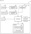
- FIGURE 3A illustrates an example UE 116 according to the present disclosure.
- the embodiment of the UE 116 illustrated in FIGURE 3A is for illustration only, and the UEs 111-115 of FIGURE 1 can have the same or similar configuration.
- UEs come in a wide variety of configurations, and FIGURE 3A does not limit the scope of the present disclosure to any particular implementation of a UE.
- the UE 116 includes an antenna 305, a radio frequency (RF) transceiver 310, transmit (TX) processing circuitry 315, a microphone 320, and receive (RX) processing circuitry 325.
- the UE 116 also includes a speaker 330, a processor 340, an input/output (I/O) interface 345, an input 350, a display 355, and a memory 360.
- the memory 360 includes an operating system (OS) program 361 and one or more applications 362. However, all of the illustrated components are not essential.
- the UE 116 may be implemented by more or less components than those illustrated in FIGURE 3A .
- the RF transceiver 310 receives, from the antenna 305, an incoming RF signal transmitted by a gNB of the wireless network 100 of FIGURE 1 .
- the RF transceiver 310 down-converts the incoming RF signal to generate an intermediate frequency (IF) or baseband signal.
- IF or baseband signal is sent to the RX processing circuitry 325, which generates a processed baseband signal by filtering, decoding, and/or digitizing the baseband or IF signal.
- the RX processing circuitry 325 transmits the processed baseband signal to the speaker 330 (such as for voice data) or to the processor 340 for further processing (such as for web browsing data).
- the TX processing circuitry 315 receives analog or digital voice data from the microphone 320 or other outgoing baseband data (such as web data, e-mail, or interactive video game data) from the processor 340.
- the TX processing circuitry 315 encodes, multiplexes, and/or digitizes the outgoing baseband data to generate a processed baseband or IF signal.
- the RF transceiver 310 receives the outgoing processed baseband or IF signal from the TX processing circuitry 315 and up-converts the baseband or IF signal to an RF signal that is transmitted via the antenna 305.
- the processor 340 can include one or more processors or other processing devices and execute the OS program 361 stored in the memory 360 in order to control the overall operation of the UE 116.
- the processor 340 can control the reception of forward channel signals and the transmission of reverse channel signals by the RF transceiver 310, the RX processing circuitry 325, and the TX processing circuitry 315 in accordance with well-known principles.
- the processor 340 includes at least one microprocessor or microcontroller.
- the processor 340 can execute other processes and programs resident in the memory 360, such as operations for NZP or ZP CSI-RS reception and measurement for systems described in embodiments of the present disclosure as described in embodiments of the present disclosure.
- the processor 340 can move data into or out of the memory 360 as part of an executing process.
- the processor 340 is configured to execute the applications 362 based on the OS program 361 or in response to signals received from gNBs or an operator.
- the processor 340 is also coupled to the I/O interface 345, which provides the UE 116 with the ability to connect to other devices such as laptop computers and handheld computers.
- the I/O interface 345 is the communication path between these accessories and the processor 340.
- the processor 340 is also coupled to the input 350 (e.g., keypad, touchscreen, button etc.) and the display 355.
- the operator of the UE 116 can use the input 350 to enter data into the UE 116.
- the display 355 can be a liquid crystal display or other display capable of rendering text and/or at least limited graphics, such as from web sites.
- the memory 360 is coupled to the processor 340.
- the memory 360 can include at least one of a random-access memory (RAM), Flash memory, or other read-only memory (ROM).
- RAM random-access memory
- ROM read-only memory
- the UE 116 can perform signaling and calculation for CSI reporting.
- FIGURE 3A illustrates one example of UE 116
- various changes can be made to FIGURE 3A .
- various components in FIGURE 3A can be combined, further subdivided, or omitted and additional components can be added according to particular needs.
- the processor 340 can be divided into multiple processors, such as one or more central processing units (CPUs) and one or more graphics processing units (GPUs).
- FIGURE 3A illustrates the UE 116 as a mobile telephone or smartphone, UEs can be configured to operate as other types of mobile or stationary devices.
- FIGURE 3B illustrates an example gNB 102 according to the present disclosure.
- the embodiment of the gNB 102 shown in FIGURE 3B is for illustration only, and other gNBs of FIGURE 1 can have the same or similar configuration.
- gNBs come in a wide variety of configurations, and FIGURE 3B does not limit the scope of the present disclosure to any particular implementation of a gNB.
- the gNB 101 and the gNB 103 can include the same or similar structure as the gNB 102.
- the terms "gNB" and "BS" are used in the present disclosure to refer to network infrastructure components that provide wireless access to remote terminals.
- the gNB 102 includes multiple antennas 370a-370n, multiple RF transceivers 372a-372n, transmit (TX) processing circuitry 374, and receive (RX) processing circuitry 376.
- one or more of the multiple antennas 370a 370n include 2D antenna arrays.
- the gNB 102 also includes a controller/processor 378, a memory 380, and a backhaul or network interface 382. However, all of the illustrated components are not essential. The gNB 102 may be implemented by more or less components than those illustrated in FIGURE 3B .
- the RF transceivers 372a-372n receive, from the antennas 370a-370n, incoming RF signals, such as signals transmitted by UEs or other gNBs.
- the RF transceivers 372a-372n down-convert the incoming RF signals to generate IF or baseband signals.
- the IF or baseband signals are sent to the RX processing circuitry 376, which generates processed baseband signals by filtering, decoding, and/or digitizing the baseband or IF signals.
- the RX processing circuitry 376 transmits the processed baseband signals to the controller/ processor 378 for further processing.
- the TX processing circuitry 374 receives analog or digital data (such as voice data, web data, e-mail, or interactive video game data) from the controller/processor 378.
- the TX processing circuitry 374 encodes, multiplexes, and/or digitizes the outgoing baseband data to generate processed baseband or IF signals.
- the RF transceivers 372a-372n receive the outgoing processed baseband or IF signals from the TX processing circuitry 374 and up-converts the baseband or IF signals to RF signals that are transmitted via the antennas 370a-370n.
- the controller/processor 378 can include one or more processors or other processing devices that control the overall operation of the gNB 102. For example, the controller/processor 378 can control the reception of forward channel signals and the transmission of reverse channel signals by the RF transceivers 372a-372n, the RX processing circuitry 376, and the TX processing circuitry 374 in accordance with well-known principles. The controller/processor 378 can support additional functions as well, such as more advanced wireless communication functions. In some embodiments, the controller/ processor 378 includes at least one microprocessor or microcontroller.
- the controller/processor 378 can execute programs and other processes resident in the memory 380, such as an OS.
- the controller/processor 378 can support channel quality measurement and reporting for systems having 2D antenna arrays as described in embodiments of the present disclosure.
- the controller/processor 378 supports communications between entities, such as web RTC.
- the controller/processor 378 can move data into or out of the memory 380 as part of an executing process.
- the controller/processor 378 is also coupled to the backhaul or network interface 382.
- the backhaul or network interface 382 allows the gNB 102 to communicate with other devices or systems over a backhaul connection or over a network.
- the backhaul or network interface 382 can support communications over any suitable wired or wireless connection(s).
- the gNB 102 is implemented as part of a cellular communication system (such as one supporting 5G or new radio access technology or NR, LTE, or LTE-A)
- the backhaul or network interface 382 can allow the gNB 102 to communicate with other gNBs over a wired or wireless backhaul connection.
- the backhaul or network interface 382 can allow the gNB 102 to communicate over a wired or wireless local area network or over a wired or wireless connection to a larger network (such as the Internet).
- the backhaul or network interface 382 includes any suitable structure supporting communications over a wired or wireless connection, such as an Ethernet or RF transceiver.
- the memory 380 is coupled to the controller/processor 378.
- the memory 380 can include at least one of a RAM, a Flash memory, or other ROM.
- a plurality of instructions such as a BIS algorithm, is stored in memory. The plurality of instructions, when executed, can cause the controller/processor 378 to perform the BIS process and to decode a received signal after subtracting out at least one interfering signal determined by the BIS algorithm.
- the transmit and receive paths of the gNB 102 (implemented using the RF transceivers 372a-372n, TX processing circuitry 374, and/or RX processing circuitry 376) transmits beam reporting information to a UE.
- FIGURE 3B illustrates one example of a gNB 102
- the gNB 102 can include any number of each component shown in FIGURE 3A .
- an access point can include a number of backhaul or network interfaces 382, and the controller/processor 378 can support routing functions to route data between different network addresses.
- the gNB 102 can include multiple instances of each (such as one per RF transceiver).
- Rel. 13 LTE supports up to 16 CSI-RS antenna ports which enable a gNB to be equipped with a large number of antenna elements (such as 64 or 128). In this case, a plurality of antenna elements is mapped onto one CSI-RS port. Furthermore, up to 32 CSI-RS ports will be supported in Rel.14 LTE and Rel.15 NR. For next generation cellular systems such as 5G, it is expected that the maximum number of CSI-RS ports remain more or less the same.
- transmitter 400 of 4 For mmWave bands, although the number of antenna elements can be larger for a given form factor, the number of CSI-RS ports - which can correspond to the number of digitally precoded ports - tends to be limited due to hardware constraints (such as the feasibility to install a large number of ADCs/DACs at mmWave frequencies) as illustrated by transmitter 400 of 4.
- this transmitter may be present in the gNB 102 or the UE 116 of FIGURE 1 .
- the embodiment of the transmitter 400 shown in FIGURE 4 is for illustration only, and other transmitters can have the same or similar configuration.
- one CSI-RS port is mapped onto a large number of antenna elements which can be controlled by a bank of analog phase shifters 401.
- One CSI-RS port can then correspond to one sub-array which produces a narrow analog beam through analog beamforming 405.
- This analog beam can be configured to sweep across a wider range of angles 420 by varying the phase shifter bank across symbols or subframes or slots (wherein a subframe or a slot comprises a collection of symbols and/or can comprise a transmission time interval).
- the number of sub-arrays (equal to the number of RF chains) is the same as the number of CSI-RS ports NCSI-PORT.
- a digital beamforming unit 410 performs a linear combination across NCSI-PORT analog beams to further increase precoding gain. While analog beams are wideband (hence not frequency-selective), digital precoding can be varied across frequency sub-bands or resource blocks. Receiver operation can be conceived analogously.
- multi-beam operation refers to the overall system aspect. This includes, for the purpose of illustration, indicating the assigned DL or UL transmit (TX) beam (also termed “beam indication”), measuring at least one reference signal for calculating and performing beam reporting (also termed “beam measurement” and “beam reporting", respectively), and receiving a DL or UL transmission via a selection of a corresponding receive (RX) beam.
- TX transmit
- RX receive
- multi-beam operation is designed primarily for single transmit-receive point (TRP) and single antenna panel. Therefore, the specification supports beam indication for one TX beam wherein a TX beam is associated with a reference RS.
- the reference RS can be NZP (non-zero power) CSI-RS and/or SSB (synchronization signal block, which includes primary synchronization signal, secondary synchronization signal, and PBCH).
- DL beam indication is done via the transmission configuration indicator (TCI) field in DL-related DCI which includes an index to one (e.g., only one) assigned reference RS.
- TCI transmission configuration indicator
- the reference RS can be NZP CSI-RS, SSB, and/or SRS.
- UL beam indication is done via the SRS resource indicator (SRI) field in UL-related DCI which is linked to one (e.g., only one) reference RS. This linkage is configured via higher-layer signaling using the SpatialRelationInfo RRC parameter. Essentially, only one TX beam may be indicated to the UE.
- SRI SRS resource indicator
- the most resource-efficient DL beam reporting mechanism is aperiodic (in conjunction with aperiodic CSI-RS).
- periodic beam reporting followsed by semi-persistent results in the lowest latency at the expense of resources.
- aperiodic beam reporting seems preferred from the overall operational perspective, in a few relevant scenarios the NW/gNB lacks knowledge on the DL channel condition - or, in other words, the UE knows the DL channel condition better. In this case, it is clearly beneficial if the UE can initiate its own aperiodic beam reporting.
- the loss of link due to beam failure can be avoided if the UE can transmit an aperiodic beam report without having to wait for a beam report (CSI) request/trigger from the NW/gNB.
- CSI beam report
- both FDD and TDD are considered as the duplex method for both DL and UL signaling.
- orthogonal frequency division multiplexing OFDM
- orthogonal frequency division multiple access OFDMA
- embodiments of the present disclosure can be extended to other OFDM-based transmission waveforms or multiple access schemes such as filtered OFDM (F-OFDM).
- F-OFDM filtered OFDM
- the present disclosure includes several components which can be used in conjunction or in combination with one another or can operate as standalone schemes.
- the term "activation" describes an operation wherein a UE receives and decodes a signal from the network (or gNB) that signifies a starting point in time.
- the starting point can be a present or a future slot/subframe or symbol - the exact location either implicitly or explicitly indicated, or otherwise fixed or higher-layer configured.
- the UE responds accordingly.
- the term “deactivation” describes an operation wherein a UE receives and decodes a signal from the network (or gNB) that signifies a stopping point in time.
- the stopping point can be a present or a future slot/subframe or symbol - the exact location either implicitly or explicitly indicated, or otherwise fixed or higher-layer configured.
- the UE responds accordingly.
- Terminology such as UL TX beam is used for illustrative purposes and therefore not normative.
- Other terms such as UL transmit spatial filter referring to a spatial filtering operation applied by the UE on a transmitted UL signal, can also be used to represent the same functions.
- a “reference RS” corresponds to a set of characteristics of UL TX beam (or UL transmit spatial filter), such as direction, precoding/beamforming, number of ports, etc. For instance, as the UE receives a reference RS index/ID in an UL grant, the UE applies the known characteristics of the reference RS to the granted UL transmission.
- the reference RS can be received and measured by the UE (in this case, the reference RS is a downlink signal such as NZP CSI-RS and/or SSB) with the result of the measurement used for calculating a beam report.
- the NW/gNB receives the beam report, the NW can be better equipped with information to assign a particular UL TX beam to the UE.
- the reference RS can be transmitted by the UE (in this case, the reference RS is a downlink signal such as SRS or DMRS).
- the NW/gNB can measure and calculate the information to assign a particular UL TX beam to the UE.
- the reference RS can be dynamically triggered by the NW/gNB (e.g. via DCI in case of aperiodic RS), preconfigured with a certain time-domain behavior (such as periodicity and offset, in case of periodic RS), or a combination of such pre-configuration and activation/deactivation (in case of semi-persistent RS).
- Beam reporting can be configured as CSI reporting with reporting metric for beam management switched ON.
- Some examples of beam management metric are L1-RSRP and L1-SINR (with various possible embodiments).
- the following embodiment is an example of DL multi-beam operation that utilizes DL beam indication after the network (NW) receives some transmission from the UE.
- NW network
- aperiodic CSI-RS is transmitted by the NW and measured by the UE.
- aperiodic RS is used in these two examples, periodic or semi-persistent RS can also be used.
- transmission-reception process includes the receiver to select a receive (RX) beam for a given TX beam.
- RX receive
- the UE selects a DL RX beam for every DL TX beam (which corresponds to a reference RS, represented by a TCI state). Therefore, the NW/gNB triggers or configures the UE to receive a DL RS (which is associated with a selection of DL TX beam).
- the UE upon receiving and measuring the DL RS, calculates a beam report and transmits it to the gNB/NW, which in turn selects a DL TX beam.
- the NW/gNB can perform this operation for all the configured reference RSs or TCI states (either per reference RS or "beam sweeping") and determine all the TX-RX beam pairs associated with the reference RSs (TCI states) configured to the UE.
- a DL multi-beam operation starts with the gNB/NW signaling to a UE an aperiodic CSI-RS (AP-CSI-RS) trigger or indication (step 501).
- This trigger or indication can be included in a DCI (either UL-related or DL-related, either separately or jointly signaled with an aperiodic CSI request/trigger) and indicate transmission of AP-CSI-RS in a same (zero time offset) or later slot/sub-frame (>0 time offset).
- the UE Upon receiving the AP-CSI-RS transmitted by the gNB/NW (step 502), the UE measures the AP-CSI-RS and, in turn, calculates and reports a "beam metric" (included in the CSI, indicating quality of a particular TX beam hypothesis) (step 503).
- beam reporting supported in Rel.15/16 NR
- beam reporting are CSI-RS resource indicator (CRI) or SSB resource indicator (SSB-RI) coupled with its associated L1-RSRP and/or L1-SINR.
- the NW/gNB can use the beam report to select a DL TX beam for the UE and indicate the DL TX beam selection (step 504) using the TCI field in the DL-related DCI (that carries the DL assignment, such as DCI format 1_1 in NR).
- the TCI state corresponds to a reference RS (in this case, an AP-CSI-RS) defined/configured via the TCI state definition (higher-layer/RRC configured, from which a subset is activated via MAC CE for the DCI-based selection).
- the UE Upon successfully decoding the DL-related DCI with the TCI field, the UE performs DL reception (such as data transmission on PDSCH) with the DL TX beam associated with the TCI field (step 505). In this example embodiment, only one DL TX beam is indicated to the UE.
- REI Resource Indicator
- CRI CSI-RS resource indicator
- SSB-RI SSB resource indicator
- Any other RS can also be used for signal/channel and/or interference measurement such as DMRS.
- a first component includes example embodiments of UE procedures for UE-initiated or UE-triggered aperiodic beam reporting.
- a second component includes example embodiments for reporting content.
- a third component includes example embodiments for UL control information (UCI) multiplexing (with and without data).
- UCI UL control information
- each of these components can be used either alone (without the other component) or in conjunction with at least one of the other components.
- each of these components includes a plurality of sub-components.
- Each of the sub-components can be used either alone (without any other sub-component) or in conjunction with at least one of the other sub-components.
- beam reporting can be included in or performed separately from CSI reporting.
- UE-initiated or UE-triggered reporting can be illustrated in an example flowchart 600 of FIGURE 6 wherein the UE is configured to report N_k ⁇ K_k beam metrics (for example, either L1-RSRP, L1-SINR, or CSI) accompanied with a set of N_k BIs ⁇ BI(0),BI(1),...,BI(N_k-1) ⁇ wherein the n-th beam metric corresponds to BI(n).
- the UE-k is configured to monitor/measure K_k beams (step 601) where beam measurement is performed on the RS associated with the beams (such as CSI-RS).
- UE-k initiatively reports the beam metric reporting indicator followed by the associated beam metric report (either N_k ⁇ K_k beam metrics along with the associated beam indices, or all the K_k beam metrics) to the network (step 602 and 603).
- the UE can report the beam metrics with the associated beam indices for Z_k out of N_k beams.
- the UE can also indicate the indices of Z_k beam reports in the last reported aperiodic beam reporting that are replaced/updated with these "new" Z_k beam reports.
- the value Z_k is either fixed or reported by the UE or configured (via higher layer or dynamic MAC CE or DCI based signaling).
- the UE-k recommends to the network a subset of N_k beams to be used for DL data transmission to UE-k (step 703, analogous to CSI-RS ports in NR).
- the value of N_k can be chosen by UE-k (either reported separately or included in the beam metric report) or configured/assigned by the network (dynamically, signaled via L1/L2 DL control signaling), or both (UE reporting a subset to the network, and the network assigns the subset based on or in response to UE reporting).
- the value of N_k is assigned by the network and signaled via L1 DL control signaling, it can be included in a DCI that requests/triggers UE-k to report aperiodic beam metric.
- the beam metrics are accompanied with the corresponding beam indices.
- the UE is configured to measure the RS associated with the M_k beams followed by CSI calculation and reporting (step 604, via an UL channel).
- This reporting can be performed aperiodically (network requesting the report via L1 DL control channel) or periodically/semi-persistently.
- the CSI reporting is used for the network to perform slot-by-slot link adaptation and scheduling. If the CSI includes RI, PMI, and CQI, the network can perform a precoded DL transmission wherein a precoder is applied across the M_k beams to generate a desired number of layers (transmission rank).
- the CQI is calculated conditioned on RI and PMI (where a codebook can be used).
- This precoding performs selection and/or combination of the M_k beams for UE-k wherein the selection refers to selecting a subset of the M_k beams and the combination refers to applying a precoder (or weights) to the selected subset of the M_k beams if the selected subset comprises a plurality of beams.
- the CSI includes at least one beam metric such as SS-RSRP or CSI-RSRP or SS-SINR or CSI-SINR, each potentially accompanied with the respective CRI or SSB-RI.
- the number of beams M_k is functionally analogous to the number of CSI-RS ports for NR.
- the network can select this number M_k based on the value of N_k reported by the UE.
- This value M_k is dynamically signaled to UE-k via a DL channel - either together with the aperiodic CSI request (for aperiodic CSI reporting, included in the associated DCI) or separately from CSI reporting (multiplexed with some other signaling either in time- or frequency-domain).
- the value M_k can also be selected by UE-k itself or reported by the UE-k but assigned by the network based on or in response to UE reporting.
- the number of beams used for that particular DL transmission M_k ( ⁇ K_k) is signaled, either separately from or together with the DL assignment (step 605).
- the M_k beams in step 604 can be a subset of the N_k beams in step 603.
- the set of M_k beams can be configured to the UE using a ⁇ log 2 N k M k ⁇ bits signaling or a size-N _k bitmap (via e.g. DCI).
- the M_k beams in step 704 can be identical to the N_k beams in step 603.
- Steps 604 and 605 can be repeated until UE-k initiates another aperiodic reporting (via, e.g. transmitting beam reporting indication) of N_k ⁇ K_k beam metrics (step 606). This is done, for instance, to ensure that UE-k is assigned a good set of N_k beams for the purpose of DL channel measurement for DL transmission.
- step 603 is repeated, followed by 604 and 605.
- step 603 and 604 yield the same type of report especially if M_k is set to be equal to N_k. In this case, step 603 and 604 can be merged especially when UE-k is configured to report aperiodic CSI.
- the core features pertaining to UE-initiated/triggered reporting are steps 602 (along with 603) and 606 in flowchart 600.
- UE-k initiates the beam reporting instead of waiting for the gNB/NW to request the report.
- Step 606 is basically the recurrence of 602 wherein UE-k keeps monitoring and measuring the pertinent measurement RS.
- the UE can initiate/trigger AP beam/CSI reporting can solely be up to the UE, or it can also be configured/indicated by the gNB/NW (e.g. via higher layer or dynamic MAC CE or/and DCI signaling). Or, optionally, it is based on the K_k value. For instance, if K_k>t, a certain threshold, then the UE can initiate/trigger beam/CSI reporting.
- At least one of the following goals can be used to design the scheme: 1) to enhance link reliability by reducing beam failure events; 2) to reduce overall latency of DL beam selection; 3) to reduce UL reporting overhead.
- a reference or baseline reporting scheme for improvement is P/SP beam reporting.
- a reference or baseline reporting scheme for improvement is AP beam/CSI reporting.
- the following example embodiments include at least one method for UL transmission that enables UE-initiated/triggered beam reporting.
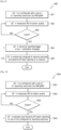
- UE-k is configured (by the NW/gNB) with Nk UL reporting resources (701), either PUCCH resources, PUSCH resources, or a combination between PUCCH and PUSCH.
- This configuration can be performed via higher-layer (RRC) signaling.
- the NW/gNB can signal the set of reserved resources dynamically via L1 and/or L2 DL control (PDCCH and/or MAC CE). These resources will be used for transmitting the AP beam/CSI report.
- UE-k is also configured with at least one measurement RS resource such as CSI-RS (NZP and/or ZP CSI-RS), SSB, or other RS types such as SRS (e.g. if beam correspondence holds).
- the measurement RSs are utilized to measure channel and/or beam quality such as CSI and/or beam metric.
- any of the measurement RSs can serve as a reference RS for beam indication (e.g. representing a TCI state).
- the beam metric can represent link quality associated with data (PDSCH) and/or dedicated control (PDCCH). Examples of such metric include L1-RSRP, L1-SINR, CQI, or hypothetical BLER, possibly accompanied with at least one measurement RS resource index/indicator.
- the UE As UE-k measures the RS to calculate beam quality (702), the UE, based on the calculated beam quality and/or other criteria, determines if the UE initiates an AP beam/CSI reporting (703).
- One of the criteria can be event-based. For example, if the beam quality metric is less than or equal to a threshold Y, UE-k will initiate AP beam/CSI reporting.
- This threshold Y can be fixed, pre-determined, configured via higher-layer (RRC) signaling, or dynamically signaled to the UE (via, e.g. PDCCH and/or MAC CE).
- the event can correspond to one particular TX beam candidate, a subset of possible TX beam candidates, or all the TX beam candidates (wherein one TX beam candidate is associated with one of the configured measurement RS resources).
- This measurement can be taken in one slot or over multiple slots (for instance, based on a pre-determined timing relationship and/or time-domain measurement restriction).
- the associated beam quality can correspond to beam metric such as L1-RSRP or L1-SINR or CQI or hypothetical BLER, measured on RS resources associated with data and/or control transmissions. It can also be associated with failure events such as beam failure detection (which represents the quality of the link used for PDCCH transmission).
- the UE transmits the AP beam/CSI reporting.
- This UE-initiated AP beam/CSI reporting can be transmitted over at least one of the configured or reserved Nk resources in slot n (704).
- step 603 is performed without 602.
- the UE can (autonomously) select a subset of the configured or reserved Nk resources.
- the gNB can infer the selected UL reporting resource(s) by decoding the AP beam/CSI reporting.
- the gNB can infer the selected UL reporting resource(s) from the rule(s).
- the gNB may be required to perform blind decoding across the Nk configured/reserved UL reporting resources. Such blind decoding involves first detecting the presence of UCI (via, e.g. CRC check). If the presence of UCI is detected, the content of UCI can be decoded.
- This embodiment results in the lowest latency since the AP beam/CSI reporting is performed in one step. However, missed detection or false alarm (on each of the Nk hypotheses) can occur more frequently.
- error detection mechanism is beneficial, e.g. CRC check on UCI (append CRC on UCI), or syndrome-based decoding for LDPC. Furthermore, it is beneficial to introduce a mechanism to differentiate UCI-only from UCI+data as well as data-only.
- the configured UL reporting resources whenever unused for AP beam/CSI reporting, can also be used for data transmission.
- content-dependent CRC or content-dependent error detection mechanism, such as scrambling
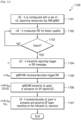
- UE-k is configured (by the NW/gNB) with Nk UL reporting resources (801), either PUCCH resources, PUSCH resources, or a combination between PUCCH and PUSCH.
- This configuration can be performed via higher-layer (RRC) signaling.
- the NW/gNB can signal the set of reserved resources dynamically via L1 and/or L2 DL control (PDCCH and/or MAC CE). These resources will be used for transmitting the AP beam/CSI report.
- UE-k is also configured with at least one measurement RS resource such as CSI-RS (NZP and/or ZP CSI-RS), SSB, or other RS types such as SRS (e.g. if beam correspondence holds).
- the measurement RSs are utilized to measure channel and/or beam quality such as CSI and/or beam metric.
- any of the measurement RSs can serve as a reference RS for beam indication (e.g. representing a TCI state).
- the beam metric can represent link quality associated with data (PDSCH) and/or dedicated control (PDCCH). Examples of such metric include L1-RSRP, L1-SINR, CQI, or hypothetical BLER, possibly accompanied with at least one measurement RS resource index/indicator.
- the UE As UE-k measures the RS to calculate beam quality (802), the UE, based on the calculated beam quality and/or other criteria, determines if the UE initiates an AP beam/CSI reporting (803).
- One of the criteria can be event-based. For example, if the beam quality metric is less than or equal to a threshold Y, UE-k will initiate AP beam/CSI reporting.
- This threshold Y can be fixed, pre-determined, configured via higher-layer (RRC) signaling, or dynamically signaled to the UE (via, e.g. PDCCH and/or MAC CE).
- the event can correspond to one particular TX beam candidate, a subset of possible TX beam candidates, or all the TX beam candidates (wherein one TX beam candidate is associated with one of the configured measurement RS resources).
- This measurement can be taken in one slot or over multiple slots (for instance, based on a pre-determined timing relationship and/or time-domain measurement restriction).
- the associated beam quality can correspond to beam metric such as L1-RSRP or L1-SINR or CQI or hypothetical BLER, measured on RS resources associated with data and/or control transmissions. It can also be associated with failure events such as beam failure detection (which represents the quality of the link used for PDCCH transmission).
- the UE first transmits a reporting trigger message to the NW/gNB to request for an UL grant (which includes AP CSI request) for transmitting the AP beam/CSI reporting (step 804) in slot n.
- the gNB/NW receives and decodes the reporting trigger message in slot n + X + ⁇ N (step 805)
- the gNB/NW transmits an UL grant (e.g. on PDCCH) to the UE which includes AP CSI request (step 806) in slot n + X + ⁇ N where X is the additional processing time.
- the UE receives and decodes the UL grant, the UE transmit the AP beam/CSI reporting on an UL reporting resource in slot n + X + ⁇ N + ⁇ U (807).
- step 602 is first performed, followed by 603.
- the UE can (autonomously) select a subset of the configured or reserved Nk resources.
- the UE can (autonomously) select a subset of the configured or reserved Nk resources.
- the AP beam/CSI reporting includes an indication of the selected UL reporting resource(s)
- the gNB can infer the selected UL reporting resource(s) by decoding the AP beam/CSI reporting.
- the NW/gNB can indicate the resource allocation for the AP beam/CSI reporting in the UL grant (step 806).
- the indication of the selected UL reporting resource(s) can also be included in the UE reporting trigger or SR (step 804).
- the NW/gNB can follow the UL resource selection from the UE without having to indicate the UL reporting resource(s) in in the UL grant, or the NW/gNB can still indicate the resource allocation for the AP beam/CSI reporting in the UL grant (this is beneficial if the UL reporting resource indication is not successfully received/decoded.
- the gNB can infer the selected UL reporting resource(s) from the rule(s).
- the gNB may be required to perform blind decoding across the Nk configured/reserved UL reporting resources.
- Such blind decoding involves first detecting the presence of UCI (via, e.g. CRC check). If the presence of UCI is detected, the content of UCI can be decoded.
- This embodiment does not require the NW/gNB to perform blind decoding thereby the least imposing one in terms of gNB baseband complexity. It is arguably the most efficient in terms of UL reporting resource. However, this embodiment results in increased latency (compared to 1.1, the latency increases by X + ⁇ N + ⁇ U ) . In addition, since this embodiment involves more steps, it may be more prone to error events especially if the gNB/NW fails to correctly receive the SR, either due to first-order DTX/missed detection (lost reporting request/opportunity, which could further cause the UE to expect an UL grant and thereby susceptible to a second-order false alarm) or first-order false alarm (which will cause increased DL interference, wasted UL resource allocation). This is likely since SR typically lacks error detection capability. On the other hand, missed detection of UL is less likely since UL grant is typically CRC protected.
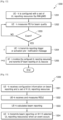
- UE-k is configured (by the NW/gNB) with Nk UL reporting resources (901), either PUCCH resources, PUSCH resources, or a combination between PUCCH and PUSCH.
- This configuration can be performed via higher-layer (RRC) signaling.
- the NW/gNB can signal the set of reserved resources dynamically via L1 and/or L2 DL control (PDCCH and/or MAC CE). These resources will be used for transmitting the AP beam/CSI report.
- UE-k is also configured with at least one measurement RS resource such as CSI-RS (NZP and/or ZP CSI-RS), SSB, or other RS types such as SRS (e.g. if beam correspondence holds).
- the measurement RSs are utilized to measure channel and/or beam quality such as CSI and/or beam metric.
- any of the measurement RSs can serve as a reference RS for beam indication (e.g. representing a TCI state).
- the beam metric can represent link quality associated with data (PDSCH) and/or dedicated control (PDCCH). Examples of such metric include L1-RSRP, L1-SINR, CQI, or hypothetical BLER, possibly accompanied with at least one measurement RS resource index/indicator.
- the UE As UE-k measures the RS to calculate beam quality (902), the UE, based on the calculated beam quality and/or other criteria, determines if the UE initiates an AP beam/CSI reporting (903).
- One of the criteria can be event-based. For example, if the beam quality metric is less than or equal to a threshold Y, UE-k will initiate AP beam/CSI reporting.
- This threshold Y can be fixed, pre-determined, configured via higher-layer (RRC) signaling, or dynamically signaled to the UE (via, e.g. PDCCH and/or MAC CE).
- the event can correspond to one particular TX beam candidate, a subset of possible TX beam candidates, or all the TX beam candidates (wherein one TX beam candidate is associated with one of the configured measurement RS resources).
- This measurement can be taken in one slot or over multiple slots (for instance, based on a pre-determined timing relationship and/or time-domain measurement restriction).
- the associated beam quality can correspond to beam metric such as L1-RSRP or L1-SINR measured on RS resources associated with data and/or control transmissions. It can also be associated with failure events such as beam failure detection (which represents the quality of the link used for PDCCH transmission).
- the UE first transmits a reporting trigger message or pre-notification message to the NW/gNB (step 904).
- this pre-notification message is transmitted as a notification to the NW/gNB that the UE is about to transmit an AP beam/CSI reporting ⁇ slots later. That is, UE-k does not wait for an UL grant to transmit the AP beam/CSI reporting. It simply gives the NW/gNB sometime to receive and process (decode) the pre-notification message so that the NW/gNB is aware that the report is coming.
- the indication of the selected UL reporting resource(s) can also be included in the pre-notification message.
- the offset ⁇ can be pre-determined/fixed, configured via higher-layer (RRC) signaling, or signaled to UE-k via L1 (PDCCH, either UE-specific or UE-group DCI) or L2 (MAC CE) DL control channel or a combination of the two.
- RRC higher-layer
- the pre-notification message can be transmitted on PUCCH (as a standalone message or multiplexed with other UCI or HARQ-ACK) or PUSCH (UCI-only or also multiplexed with data).
- UE-k can monitor PDCCH for the presence of an UL grant with resource allocation including any subset of the Nk pre-configured UL reporting resources.
- the UE can simply check if that is the case only in slot (n+ ⁇ -1) or (n+ ⁇ ). This is performed to see if any of the Nk pre-configured UL reporting resources is used for other purposes, i.e. "grant-based" UCI and/or data transmission.
- UE-k can select any subset of the Nk pre-configured UL reporting resources that are free (unused) for the purpose of the UE-triggered/initiated AP beam/CSI reporting in slot n+ ⁇ (step 905).
- UE-k can be expected to monitor the presence of UL grant(s) for itself (i.e. whether the UL reporting resource(s) pre-configured for UE-k are used for other UEs should not concern UE-k and is left to the NW/gNB).
- UE-k can choose any from the Nk pre-configured UL reporting resources. By doing so, if/when the NW/gNB receives the pre-notification message transmitted in slot n, the NW/gNB may know that the UL reporting resource(s) indicated in the pre-notification message cannot be used in any UL grant for UE-k in slot n+ ⁇ .
- step 602 is first performed, followed by 603.
- the UE can (autonomously) select a subset of the configured or reserved Nk resources.
- the UE can (autonomously) select a subset of the configured or reserved Nk resources.
- the AP beam/CSI reporting includes an indication of the selected UL reporting resource(s)
- the gNB can infer the selected UL reporting resource(s) by decoding the AP beam/CSI reporting.
- the indication of the selected UL reporting resource(s) is included in the pre-notification message
- the gNB can infer the selected UL reporting resource(s) by decoding the pre-notification message.
- the gNB can infer the selected UL reporting resource(s) from the rule(s).
- the gNB may be required to perform blind decoding across the Nk configured/reserved UL reporting resources. Such blind decoding involves first detecting the presence of UCI (via, e.g. CRC check). If the presence of UCI is detected, the content of UCI can be decoded.
- the pool for UL reporting resource selection the following possibilities exist. First, it can be done from all the pre-configured or reserved Nk resources. Second, optionally, it can be done from a subset of the pre-configured or reserved Nk resources not used in at least one UL grant as described in the previous paragraph, i.e. between slot n (transmission of pre-notification message) and n+ ⁇ (transmission of AP beam/CSI reporting), or slot (n+ ⁇ 1), or (n+ ⁇ ).
- This embodiment may require the NW/gNB to perform blind decoding if the selected UL reporting resource is not indicated. In terms of latency and resource usage efficiency, it is in between embodiments I.1 and I.2. While it does not involve as many steps as embodiment I.3, it is still susceptible to missed detection and false alarm in decoding the trigger/pre-notification message.
- the condition for transmitting AP beam/CSI reporting is based on at least one measurement-based event.
- Other conditions can also be used.
- the condition or event does not have to be specified. That is, the UE can initiate an AP beam/CSI reporting by itself without any specified condition. This can be relevant if a number of different link/channel conditions are expected to warrant UE-initiated/triggered AP beam/CSI reporting.
- the beam/CSI reporting is assumed to be aperiodic (AP) wherein the UE reports one reporting instance.
- AP aperiodic
- Any of the above embodiments can also be extended to semi-persistent (SP) beam/CSI reporting (which involves activation and deactivation of the SP report and, if SP CSI-RS is used, its corresponding measurements).
- SP semi-persistent
- Several options are possible. In a first option, when the condition for transmitting SP beam/CSI reporting is fulfilled, the UE activates the SP beam/CSI reporting and, depending on the scheme, starts to transmit the report.
- At least one of the periodicity, slot offset, and/or the number of reporting instances can be either pre-determined/fixed, configured via higher-layer (RRC) signaling, or signaled to the UE via L1 (PDCCH, either UE-specific or UE-group DCI) and/or L2 (MAC CE) DL control channel.
- RRC higher-layer
- a second option is similar to the first option except that at least one of the periodicity, slot offset, and/or the number of reporting instances can be chosen by the UE and reported to the NW/gNB either separately or together with the SP beam/CSI reporting.
- FIGURE 7 , 8 , and 9 for aperiodic reporting can be extended to those illustrated in FIGURE 10 , 11 , and 12 , respectively, for semi-persistent reporting as follows.
- deactivation of SP reporting is not shown.
- deactivation can be accomplished either implicitly (e.g. via gNB/NW configuration and UE selection of the number of reporting instances) or explicitly (the UE sending a deactivation request/notification to the gNB/NW which can be signaled separately or together with the SP beam/CSI reporting).
- the SP beam/CSI reporting can be performed either via PUCCH, PUSCH, or a combination of the two.
- the beam/CSI reporting can comprise a beam metric (such as L1-RSRP, L1-SINR, or a hypothetical BLER) that represents link quality for data and/or dedicated control. If data and control TX beams can be the same (unlike in Rel. 15/16), the same beam metric can be used to represent both data and control.
- a beam metric such as L1-RSRP, L1-SINR, or a hypothetical BLER
- the beam/CSI reporting can comprise a measure or status for beam failure event on dedicated control (PDCCH).
- the failure event can be defined in several options. In one option, beam failure event is declared when at least one of the candidate TX beams (associated with the configured CSI-RS or SSB resources for beam management) fails. In another option, beam failure is declared when all of the candidate TX beams (associated with the configured CSI-RS or SSB resources for beam management) fails. A failure for a TX beam candidate can correspond to the associated beam metric falling below a given threshold. If reported beam metric represents the quality of dedicated control reception, this may be unnecessary.
- the UCI can be reported alone or transmitted/multiplexed together with data.
- the associated beam/CSI reporting can be transmitted either via PUCCH or PUSCH.
- the associated beam/CSI reporting can be transmitted via PUSCH.
- the two-part UCI (comprising part 1 UCI and part 2 UCI, analogous to two-part UCI in Rel. 15) can be used, wherein the part 1 UCI indicates whether event is positive and negative, and if the event is positive, then the part 2 UCI including the AP beam/CSI using the configured/reserved UL reporting resources.
- the part 1 UCI can be reported using the first subset of the Nk resources, and the part 2 UCI can be reported using a second subset of the remaining resources (according to the three methods explained above).
- the AP beam/CSI reporting includes an indication of the selected UL reporting resource(s)
- this indication can also be included in part 1 UCI.
- the SP beam/CSI reporting includes an indication of the selected UL reporting resource(s) and/or (optionally) information on periodicity, slot offset, and/or the number of reporting instances, at least one of this information can be included in part 1 UCI.
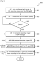
- FIGURE 13 illustrates a flowchart for an example method 1300 wherein a UE receives configuration information on beam reporting and UL reporting resource according to an embodiment of the present disclosure.
- the method 1300 can be performed by the UE 116.
- the embodiment of the method 1300 shown in FIGURE 13 is for illustration only.
- the method 1300 begins with the UE (termed UE-k) receiving, from a base station, configuration information on beam reporting and UL reporting resource wherein a set of K UL reporting resources are configured for UE-k (step 1301). UE-k also receives and measures at least one RS resource (step 1302) for calculating the beam reporting (1303). When an event occurs, UE-k transmits the beam reporting on a selected N-subset (i.e., N ⁇ K) of UL reporting resources (step 1304).
- N-subset i.e., N ⁇ K
- the beam reporting can include at least one beam metric (such as CSI-RSRP, CSI-SINR, SSB-RSRP, SSB-SINR, or any combination or modification thereof) or CQI, each accompanied by the respective CRI or SSB-RI. Consequently, any one of the RS resources can be CSI-RS or SSB or, if beam correspondence holds, SRS.
- the UL reporting resource can be allocated on PUCCH, PUSCH, or a combination of the two.
- the beam reporting includes beam metric
- the event can include at least one of the RSRP or SINR value smaller than a threshold. This indicates that the beam quality is degrading, and UE-k is to let the gNB/network know.
- UE-k can transmit a reporting trigger and, subsequently, wait for receiving an uplink grant prior to transmitting the beam reporting.
- UE-k can transmit a reporting pre-notification message prior to transmitting the beam reporting (that is, without waiting for receiving an uplink grant).
- the reporting pre-notification message includes an information on the N selected UL reporting resource(s).
- FIGURE 14 illustrates a flowchart for an example method 1400 wherein a BS generates configuration information on beam reporting and UL reporting resource to a UE (labeled as UE-k) according to an embodiment of the present disclosure.
- the method 1400 can be performed by the BS 102.
- the embodiment of the method 1400 shown in FIGURE 14 is for illustration only.
- the method 1400 begins with the BS generating and transmitting, to UE-k begins with the UE receiving, from a base station, configuration information on beam reporting and UL reporting resource wherein a set of K UL reporting resources are configured for UE-k (step 1401).
- the BS also generates and transmits at least one RS resource (step 1402) for UE-k to calculate the beam reporting.
- the BS receives the beam reporting on a selected N-subset (i.e., N ⁇ K) of UL reporting resources (step 1303).
- the beam reporting can include at least one beam metric (such as CSI-RSRP, CSI-SINR, SSB-RSRP, SSB-SINR, or any combination or modification thereof) or CQI, each accompanied by the respective CRI or SSB-RI. Consequently, any one of the RS resources can be CSI-RS or SSB or, if beam correspondence holds, SRS.
- the UL reporting resource can be allocated on PUCCH, PUSCH, or a combination of the two.
- the beam reporting includes beam metric
- the event can include at least one of the RSRP or SINR value smaller than a threshold. This indicates that the beam quality is degrading, and UE-k is to let the gNB/network know.
- the BS can wait for receiving a reporting trigger and, subsequently, transmits an uplink grant prior to receiving the beam reporting.
- the BS can wait for receiving a reporting pre-notification message prior to receiving the beam reporting (that is, without transmitting an uplink grant to UE-k).
- the reporting pre-notification message includes an information on the N selected UL reporting resource(s).
- FIGURES 13 and 14 illustrate examples of methods for receiving configuration information and configuring a UE, respectively, various changes can be made to FIGURES 13 and 14 .
- steps in each figure can overlap, occur in parallel, occur in a different order, occur multiple times, or not be performed in one or more embodiments.
- FIGURE 15 illustrates a base station according to embodiments of the present disclosure.
- the user equipment 1500 may include a processor 1510, a transceiver 1520 and a memory 1530. However, all of the illustrated components are not essential. The user equipment 1500 may be implemented by more or less components than those illustrated in FIGURE 15 . In addition, the processor 1510 and the transceiver 1520 and the memory 1530 may be implemented as a single chip according to another embodiment.
- the user equipment 1500 may correspond to UE described above.
- the user equipment 1500 may correspond to the UE 116 illustrated in FIGURE 3A .
- the processor 1510 may include one or more processors or other processing devices that control the proposed function, process, and/or method. Operation of the user equipment 1500 may be implemented by the processor 1510.
- the transceiver 1520 may include a RF transmitter for up-converting and amplifying a transmitted signal, and a RF receiver for down-converting a frequency of a received signal.
- the transceiver 1520 may be implemented by more or less components than those illustrated in components.
- the transceiver 1520 may be connected to the processor 1510 and transmit and/or receive a signal.
- the signal may include control information and data.
- the transceiver 1520 may receive the signal through a wireless channel and output the signal to the processor 1510.
- the transceiver 1520 may transmit a signal output from the processor 1510 through the wireless channel.
- the memory 1530 may store the control information or the data included in a signal obtained by the user equipment 1500.
- the memory 1530 may be connected to the processor 1510 and store at least one instruction or a protocol or a parameter for the proposed function, process, and/or method.
- the memory 1530 may include read-only memory (ROM) and/or random access memory (RAM) and/or hard disk and/or CD-ROM and/or DVD and/or other storage devices.
- FIGURE 16 illustrates a base station according to embodiments of the present disclosure.
- the base station 1600 may include a processor 1610, a transceiver 1620 and a memory 1630. However, all of the illustrated components are not essential. The base station 1600 may be implemented by more or less components than those illustrated in FIGURE 16 . In addition, the processor 1610 and the transceiver 1620 and the memory 1630 may be implemented as a single chip according to another embodiment.
- the base station 1600 may correspond to the gNB described above.
- the base station 1600 may correspond to gNB 102 illustrated in FIGURE 3B .
- the processor 1610 may include one or more processors or other processing devices that control the proposed function, process, and/or method. Operation of the base station 1600 may be implemented by the processor 1610.
- the transceiver 1620 may include a RF transmitter for up-converting and amplifying a transmitted signal, and a RF receiver for down-converting a frequency of a received signal.
- the transceiver 1620 may be implemented by more or less components than those illustrated in components.
- the transceiver 1620 may be connected to the processor 1610 and transmit and/or receive a signal.
- the signal may include control information and data.
- the transceiver 1620 may receive the signal through a wireless channel and output the signal to the processor 1610.
- the transceiver 1620 may transmit a signal output from the processor 1610 through the wireless channel.
- the memory 1630 may store the control information or the data included in a signal obtained by the base station 1600.
- the memory 1630 may be connected to the processor 1610 and store at least one instruction or a protocol or a parameter for the proposed function, process, and/or method.
- the memory 1630 may include read-only memory (ROM) and/or random access memory (RAM) and/or hard disk and/or CD-ROM and/or DVD and/or other storage devices.
Landscapes
- Engineering & Computer Science (AREA)
- Signal Processing (AREA)
- Computer Networks & Wireless Communication (AREA)
- Quality & Reliability (AREA)
- Physics & Mathematics (AREA)
- Electromagnetism (AREA)
- Mobile Radio Communication Systems (AREA)
Claims (6)
- Benutzergerät, UE (1500), Folgendes umfassend:einen Transceiver (1520); undeinen Prozessor (1510), der mit dem Transceiver (1520) gekoppelt ist und konfiguriert ist zum:Empfangen, von einer Basisstation, BS (1600), von Konfigurationsinformationen über einen Strahlenbericht,Empfangen von Konfigurationsinformationen über einen Satz von Uplink-, UL,-Berichtsressourcen,Empfangen von mindestens einer Referenzsignal-, RS,-Ressource,Messen der mindestens einen RS-Ressource zur Berechnung des Strahlenberichts,Übertragen einer Berichtsvorankündigungsnachricht auf der Grundlage des Auftretens eines Ereignisses, wobei die Berichtsvorankündigungsnachricht so konfiguriert ist, dass sie die BS (1600) darüber informiert, dass der Strahlenbericht von dem UE (1500) übertragen werden soll, undÜbertragen des Strahlenberichts auf mindestens einer UL-Berichtsressource aus dem Satz von UL-Berichtsressourcen nach dem Übertragen der Berichtsvorankündigungsnachricht,wobei die Berichtsvorankündigungsnachricht Informationen enthält, die die mindestens eine UL-Berichtsressource aus dem Satz von UL-Berichtsressourcen angeben, die für die Übertragung des Strahlenberichts verwendet werden soll.
- UE (1500) nach Anspruch 1, wobei der Prozessor (1510) ferner konfiguriert ist zum:Erkennen, dass das Ereignis eingetreten ist; undals Reaktion auf das Erkennen, dass das Ereignis eingetreten ist, Berechnen des Strahlenberichts und Veranlassen des Transceivers, den Strahlenbericht zu übertragen.
- Basisstation, BS (1600), umfassend:einen Transceiver (1620); undeinen Prozessor (1610), der mit dem Transceiver (1620) gekoppelt ist und konfiguriert ist zum:Erzeugen von Konfigurationsinformationen über einen Strahlenbericht und einen Satz von Uplink-, UL-, Berichtsressourcen;Übertragen der Konfigurationsinformationen für den Strahlenbericht und den Satz von UL-Berichtsressourcen an ein Benutzergerät, UE (1500),Übertragen mindestens einer Referenzsignal-, RS,-Ressource an das UE (1500),Empfangen einer Berichtsvorankündigungsnachricht auf der Grundlage des Auftretens eines Ereignisses, wobei die Berichtsvorankündigungsnachricht so konfiguriert ist, dass sie die BS (1600) darüber informiert, dass der Strahlenbericht von dem UE (1500) übertragen werden soll, undEmpfangen des Strahlenberichts auf mindestens einer UL-Berichtsressource aus dem Satz von UL-Berichtsressourcen nach dem Empfangen der Berichtsvorankündigungsnachricht,wobei die Berichtsvorankündigungsnachricht Informationen enthält, die die mindestens eine UL-Berichtsressource aus dem Satz von UL-Berichtsressourcen angeben, die für die Übertragung des Strahlenberichts verwendet werden soll.
- Verfahren zum Betreiben eines Benutzergeräts, UE (1500), wobei das Verfahren Folgendes umfasst:Empfangen von Konfigurationsinformationen über einen Strahlenbericht und einen Satz von Uplink-, UL,-Berichtsressourcen von einer Basisstation, BS (1600);Empfangen mindestens einer Referenzsignal-, RS,-Ressource,Messen der mindestens einen RS-Ressource zur Berechnung des Strahlenberichts;Übertragen einer Berichtsvorankündigungsnachricht auf der Grundlage des Auftretens eines Ereignisses, wobei die Berichtsvorankündigungsnachricht so konfiguriert ist, dass sie die BS (1600) darüber informiert, dass der Strahlenbericht von dem UE (1500) übertragen werden soll; undÜbertragen des Strahlenberichts auf mindestens einer UL-Berichtsressource aus dem Satz von UL-Berichtsressourcen nach dem Übertragen der Berichtsvorankündigungsnachricht,wobei die Berichtsvorankündigungsnachricht Informationen enthält, die die mindestens eine UL-Berichtsressource aus dem Satz von UL-Berichtsressourcen angeben, die für die Übertragung des Strahlenberichts verwendet werden soll.
- Verfahren nach Anspruch 4, ferner umfassend:Erkennen, dass das Ereignis aufgetreten ist; undBerechnen des Strahlenberichts als Reaktion auf die Erkennung, dass das Ereignis aufgetreten ist,wobei das Übertragen des Strahlenberichts das Übertragen des Strahlenberichts als Reaktion auf das Erkennen des Auftretens des Ereignisses umfasst.
- Verfahren zum Betreiben einer Basisstation, BS (1600), wobei das Verfahren Folgendes umfasst:Empfangen von Konfigurationsinformationen über einen Strahlenbericht und einen Satz von Uplink-, UL,-Berichtsressourcen von einer Basisstation, BS (1600);Übertragen der Konfigurationsinformationen für den Strahlenbericht und den Satz von UL-Berichtsressourcen an ein Benutzergerät, UE (1500),Übertragen mindestens einer Referenzsignal-, RS,-Ressource an das UE (1500),Empfangen einer Berichtsvorankündigungsnachricht auf der Grundlage des Auftretens eines Ereignisses, wobei die Berichtsvorankündigungsnachricht so konfiguriert ist, dass sie die BS (1600) darüber informiert, dass der Strahlenbericht von dem UE (1500) übertragen werden soll, undEmpfangen des Strahlenberichts auf mindestens einer UL-Berichtsressource aus dem Satz von UL-Berichtsressourcen nach dem Empfangen der Berichtsvorankündigungsnachricht,wobei die Berichtsvorankündigungsnachricht Informationen enthält, die die mindestens eine UL-Berichtsressource aus dem Satz von UL-Berichtsressourcen angeben, die für die Übertragung des Strahlenberichts verwendet werden soll.
Applications Claiming Priority (5)
| Application Number | Priority Date | Filing Date | Title |
|---|---|---|---|
| US201962875203P | 2019-07-17 | 2019-07-17 | |
| US201962875766P | 2019-07-18 | 2019-07-18 | |
| US202063019665P | 2020-05-04 | 2020-05-04 | |
| US15/929,912 US11510080B2 (en) | 2019-07-17 | 2020-05-28 | Method and apparatus for triggering multi-beam reporting |
| PCT/KR2020/009335 WO2021010751A1 (en) | 2019-07-17 | 2020-07-15 | Method and apparatus for triggering multi-beam report |
Publications (3)
| Publication Number | Publication Date |
|---|---|
| EP3973640A1 EP3973640A1 (de) | 2022-03-30 |
| EP3973640A4 EP3973640A4 (de) | 2022-08-03 |
| EP3973640B1 true EP3973640B1 (de) | 2024-10-09 |
Family
ID=74209929
Family Applications (1)
| Application Number | Title | Priority Date | Filing Date |
|---|---|---|---|
| EP20841177.7A Active EP3973640B1 (de) | 2019-07-17 | 2020-07-15 | Verfahren und vorrichtung zur auslösung eines mehrstrahlberichts |
Country Status (4)
| Country | Link |
|---|---|
| US (1) | US11510080B2 (de) |
| EP (1) | EP3973640B1 (de) |
| CN (1) | CN114128170A (de) |
| WO (1) | WO2021010751A1 (de) |
Families Citing this family (42)
| Publication number | Priority date | Publication date | Assignee | Title |
|---|---|---|---|---|
| FI3758426T3 (fi) * | 2018-02-20 | 2023-07-20 | Ntt Docomo Inc | Terminaali ja tukiasemalaite |
| EP4318972A3 (de) * | 2018-08-17 | 2024-04-03 | InterDigital Patent Holdings, Inc. | Strahlverwaltung für multi-trp |
| CN115885535B (zh) * | 2020-06-29 | 2026-03-24 | 株式会社Ntt都科摩 | 无线基站、终端以及通信方法 |
| CN116250195A (zh) * | 2020-09-29 | 2023-06-09 | 华为技术有限公司 | 干扰上报的方法与装置 |
| US20220311572A1 (en) * | 2021-03-25 | 2022-09-29 | Qualcomm Incorporated | Reference signal resource sets for subband measurements |
| WO2022213296A1 (en) * | 2021-04-07 | 2022-10-13 | Qualcomm Incorporated | Allocating channel state information (csi) processing unit (cpu) for user equipment (ue) -initiated csi feedback |
| US12068795B2 (en) * | 2021-11-03 | 2024-08-20 | Qualcomm Incorporated | Excessive interference indication |
| CN118511575A (zh) * | 2022-01-06 | 2024-08-16 | 高通股份有限公司 | 用于事件触发的波束组报告的技术 |
| WO2023205319A1 (en) * | 2022-04-22 | 2023-10-26 | Apple Inc. | User equipment configuration for sib and mib decoding |
| CN119096582A (zh) * | 2022-04-25 | 2024-12-06 | 苹果公司 | 半持久信道状态信息(sp-csi)增强 |
| US20240214851A1 (en) * | 2022-12-22 | 2024-06-27 | Samsung Electronics Co., Ltd. | Triggering of a report |
| US20240223340A1 (en) * | 2022-12-29 | 2024-07-04 | Samsung Electronics Co., Ltd. | Resource and reporting settings for ue initiated reporting |
| US20240224290A1 (en) * | 2023-01-03 | 2024-07-04 | Samsung Electronics Co., Ltd. | Ue-initiated csi measurement and reporting |
| US20250024294A1 (en) * | 2023-07-13 | 2025-01-16 | Samsung Electronics Co., Ltd. | Ue-initiated beam management |
| US20250158686A1 (en) * | 2023-11-13 | 2025-05-15 | Samsung Electronics Co., Ltd. | Systems and methods for user equipment (ue) initiated beam management |
| WO2025111873A1 (en) * | 2023-11-29 | 2025-06-05 | Zte Corporation | Event triggered beam reporting methods and apparatus |
| US20250203434A1 (en) * | 2023-12-13 | 2025-06-19 | Samsung Electronics Co., Ltd. | Beam reporting in a wireless communication system |
| WO2025146965A1 (en) * | 2024-01-01 | 2025-07-10 | Lg Electronics Inc. | Method and apparatus of transmitting ue initiated beam report in wireless communication system |
| WO2025152072A1 (en) * | 2024-01-17 | 2025-07-24 | Zte Corporation | Beam information report |
| WO2025152073A1 (en) * | 2024-01-17 | 2025-07-24 | Zte Corporation | Beam measurement and reporting techniques |
| WO2024260001A1 (en) * | 2024-02-06 | 2024-12-26 | Lenovo (Beijing) Limited | Performance monitoring for beam prediction |
| WO2025171558A1 (en) * | 2024-02-15 | 2025-08-21 | Apple Inc. | Control channel based user equipment (ue)-initiated beam reporting (uibr) by a ue for frequency range two (fr2) |
| WO2025175427A1 (en) * | 2024-02-19 | 2025-08-28 | Zte Corporation | Uplink control information |
| WO2025178452A1 (ko) * | 2024-02-19 | 2025-08-28 | 현대자동차주식회사 | 무선 통신 시스템에서 빔 보고를 수행하기 위한 방법 및 장치 |
| WO2025175977A1 (en) * | 2024-02-19 | 2025-08-28 | Guangdong Oppo Mobile Telecommunications Corp., Ltd. | Method of beam reporting and relevant devices |
| CN121080080A (zh) * | 2024-03-12 | 2025-12-05 | 北京小米移动软件有限公司 | 信息传输方法、终端、网络设备、通信系统及存储介质 |
| US20250294394A1 (en) * | 2024-03-15 | 2025-09-18 | Samsung Electronics Co., Ltd. | Event-driven measurement and reporting |
| WO2025199763A1 (en) * | 2024-03-26 | 2025-10-02 | Nec Corporation | Devices and methods of communication |
| WO2025156399A1 (en) * | 2024-03-27 | 2025-07-31 | Zte Corporation | Method, device and computer program product for wireless communication |
| KR20250146232A (ko) * | 2024-03-29 | 2025-10-13 | 한국전자통신연구원 | 통신 시스템에서 2단계 빔 보고의 방법 및 장치 |
| WO2025208551A1 (en) * | 2024-04-04 | 2025-10-09 | Apple Inc. | Methods for event-triggered beam management procedure to enable fast beam update in wireless communication |
| WO2025208582A1 (zh) * | 2024-04-04 | 2025-10-09 | 深圳Tcl新技术有限公司 | 波束上报的方法及无线通信设备 |
| WO2025215071A1 (en) * | 2024-04-11 | 2025-10-16 | Telefonaktiebolaget Lm Ericsson (Publ) | User equipment initiated beam reporting based on aperiodic downlink reference signals |
| WO2025039582A1 (en) * | 2024-04-12 | 2025-02-27 | Lenovo (Beijing) Limited | Method and apparatus of supporting beam reporting |
| WO2025230265A1 (en) * | 2024-04-30 | 2025-11-06 | Lg Electronics Inc. | Measurement report triggering based on quality of triggering cell and triggering cell set |
| WO2025231644A1 (en) * | 2024-05-08 | 2025-11-13 | Qualcomm Incorporated | Uplink configuration for beam reporting |
| WO2025241050A1 (en) * | 2024-05-20 | 2025-11-27 | Qualcomm Incorporated | Techniques for indicating event-based beam reporting |
| WO2025097818A1 (en) * | 2024-07-05 | 2025-05-15 | Lenovo (Beijing) Limited | Method and apparatus of supporting beam reporting |
| WO2025222644A1 (en) * | 2024-07-16 | 2025-10-30 | Zte Corporation | Control information transmission and reception |
| WO2025236395A1 (en) * | 2024-07-16 | 2025-11-20 | Zte Corporation | Procedures for user equipment-initiated or event-driven beam reporting in wireless networks |
| WO2025222645A1 (en) * | 2024-07-16 | 2025-10-30 | Zte Corporation | User equipment procedures for event-triggered beam information reporting |
| US20260040113A1 (en) * | 2024-08-05 | 2026-02-05 | Interdigital Patent Holdings, Inc. | Methods, architectures, apparatuses and systems for mobility reporting |
Family Cites Families (11)
| Publication number | Priority date | Publication date | Assignee | Title |
|---|---|---|---|---|
| WO2017070896A1 (zh) * | 2015-10-29 | 2017-05-04 | 华为技术有限公司 | 一种预测、上报小区信号强度的方法和用户设备 |
| CN106255209B (zh) * | 2016-02-04 | 2019-10-01 | 北京智谷睿拓技术服务有限公司 | 增强无线通信可靠性的方法、用户设备、基站和系统 |
| US20190173534A1 (en) * | 2016-08-11 | 2019-06-06 | Ntt Docomo, Inc. | Method for uplink transmisison |
| US10750569B2 (en) | 2017-03-03 | 2020-08-18 | Qualcomm Incorporated | Beam management for connected mode discontinuous reception operation |
| EP4048011B1 (de) | 2017-09-08 | 2025-11-12 | Samsung Electronics Co., Ltd. | Verfahren und vorrichtung zur ressourcenbestimmung, ressourcenkonfiguration, übertragung von direktzugriffspräambeln und direktzugriff |
| KR20190054978A (ko) | 2017-11-13 | 2019-05-22 | 주식회사 윌러스표준기술연구소 | 무선 통신 시스템의 통신을 위한 빔 운영 방법 및 이를 이용하는 장치 |
| WO2019136205A1 (en) | 2018-01-04 | 2019-07-11 | Ofinno, Llc | Semi-persistent channel state information report |
| EP3547564A4 (de) | 2018-01-11 | 2020-09-23 | LG Electronics Inc. -1- | Verfahren zur meldung von kanalstatusinformationen in einem drahtloskommunikationssystem und vorrichtung dafür |
| US20190296815A1 (en) | 2018-03-22 | 2019-09-26 | Samsung Electronics Co., Ltd. | Method and apparatus for high capacity access |
| US10897340B2 (en) * | 2018-04-25 | 2021-01-19 | Qualcomm Incorporated | Non-orthogonal multiple access (NOMA)-based channel quality indicator (CQI) reporting |
| US11196524B2 (en) * | 2018-07-18 | 2021-12-07 | Qualcomm Incorporated | Multi-beam CSI feedback |
-
2020
- 2020-05-28 US US15/929,912 patent/US11510080B2/en active Active
- 2020-07-15 EP EP20841177.7A patent/EP3973640B1/de active Active
- 2020-07-15 WO PCT/KR2020/009335 patent/WO2021010751A1/en not_active Ceased
- 2020-07-15 CN CN202080051708.3A patent/CN114128170A/zh active Pending
Also Published As
| Publication number | Publication date |
|---|---|
| US11510080B2 (en) | 2022-11-22 |
| CN114128170A (zh) | 2022-03-01 |
| EP3973640A4 (de) | 2022-08-03 |
| EP3973640A1 (de) | 2022-03-30 |
| WO2021010751A1 (en) | 2021-01-21 |
| US20210022026A1 (en) | 2021-01-21 |
Similar Documents
| Publication | Publication Date | Title |
|---|---|---|
| EP3973640B1 (de) | Verfahren und vorrichtung zur auslösung eines mehrstrahlberichts | |
| AU2022204501B2 (en) | Method and apparatus for multiplexing channel state information | |
| CN112956145B (zh) | 信道和干扰测量和报告的方法和装置 | |
| CN115516965B (zh) | 用于动态波束指示机制的方法和装置 | |
| US20230180259A1 (en) | Method and apparatus for beam management for multi-stream transmission | |
| CN114631386B (zh) | 用于快速波束管理的方法和装置 | |
| US11025385B2 (en) | Method and apparatus for channel state information reference signal (CSI-RS) | |
| US11206076B2 (en) | Method and apparatus for low-latency beam selection | |
| EP3998714B1 (de) | Verfahren und vorrichtung zur erfassung von kanalzustandsinformationen (csi) mit dl- und ul-referenzsignalen | |
| KR102799453B1 (ko) | 비면허 스펙트럼에서의 빔 관리 방법 및 장치 | |
| US10868604B2 (en) | Method and apparatus for reference signal for measurements | |
| EP3744121B1 (de) | Verfahren für funk-frontend-strahlverwaltung für 5g-endgeräte | |
| EP4162622B1 (de) | Verfahren und vorrichtung für uplink-übertragungsstrahlauswahlverfahren in einem drahtloskommunikationssystem | |
| CN110622459B (zh) | 信道状态信息参考信号的方法和设备 | |
| EP4373027A2 (de) | Verfahren und vorrichtung für ereignisbasierte uplink-übertragungsstrahlumschaltung | |
| US20190296815A1 (en) | Method and apparatus for high capacity access | |
| EP3782301B1 (de) | Verfahren zur endgerätespezifischen strahlformungsanpassung für fortgeschrittene drahtlose systeme | |
| CN115715456B (zh) | 用于上行链路发送波束选择的方法和装置 | |
| US20220014956A1 (en) | Uplink transmit beam selection based on downlink and uplink resource signal measurements |
Legal Events
| Date | Code | Title | Description |
|---|---|---|---|
| STAA | Information on the status of an ep patent application or granted ep patent |
Free format text: STATUS: THE INTERNATIONAL PUBLICATION HAS BEEN MADE |
|
| PUAI | Public reference made under article 153(3) epc to a published international application that has entered the european phase |
Free format text: ORIGINAL CODE: 0009012 |
|
| STAA | Information on the status of an ep patent application or granted ep patent |
Free format text: STATUS: REQUEST FOR EXAMINATION WAS MADE |
|
| 17P | Request for examination filed |
Effective date: 20211223 |
|
| AK | Designated contracting states |
Kind code of ref document: A1 Designated state(s): AL AT BE BG CH CY CZ DE DK EE ES FI FR GB GR HR HU IE IS IT LI LT LU LV MC MK MT NL NO PL PT RO RS SE SI SK SM TR |
|
| A4 | Supplementary search report drawn up and despatched |
Effective date: 20220705 |
|
| RIC1 | Information provided on ipc code assigned before grant |
Ipc: H04W 24/10 20090101ALI20220629BHEP Ipc: H04W 72/04 20090101ALI20220629BHEP Ipc: H04B 7/06 20060101ALI20220629BHEP Ipc: H04B 7/0417 20170101AFI20220629BHEP |
|
| DAV | Request for validation of the european patent (deleted) | ||
| DAX | Request for extension of the european patent (deleted) | ||
| GRAP | Despatch of communication of intention to grant a patent |
Free format text: ORIGINAL CODE: EPIDOSNIGR1 |
|
| STAA | Information on the status of an ep patent application or granted ep patent |
Free format text: STATUS: GRANT OF PATENT IS INTENDED |
|
| INTG | Intention to grant announced |
Effective date: 20240620 |
|
| GRAS | Grant fee paid |
Free format text: ORIGINAL CODE: EPIDOSNIGR3 |
|
| GRAA | (expected) grant |
Free format text: ORIGINAL CODE: 0009210 |
|
| STAA | Information on the status of an ep patent application or granted ep patent |
Free format text: STATUS: THE PATENT HAS BEEN GRANTED |
|
| AK | Designated contracting states |
Kind code of ref document: B1 Designated state(s): AL AT BE BG CH CY CZ DE DK EE ES FI FR GB GR HR HU IE IS IT LI LT LU LV MC MK MT NL NO PL PT RO RS SE SI SK SM TR |
|
| REG | Reference to a national code |
Ref country code: CH Ref legal event code: EP |
|
| REG | Reference to a national code |
Ref country code: DE Ref legal event code: R096 Ref document number: 602020039263 Country of ref document: DE |
|
| REG | Reference to a national code |
Ref country code: IE Ref legal event code: FG4D |
|
| REG | Reference to a national code |
Ref country code: LT Ref legal event code: MG9D |
|
| REG | Reference to a national code |
Ref country code: NL Ref legal event code: MP Effective date: 20241009 |
|
| REG | Reference to a national code |
Ref country code: AT Ref legal event code: MK05 Ref document number: 1731711 Country of ref document: AT Kind code of ref document: T Effective date: 20241009 |
|
| PG25 | Lapsed in a contracting state [announced via postgrant information from national office to epo] |
Ref country code: NL Free format text: LAPSE BECAUSE OF FAILURE TO SUBMIT A TRANSLATION OF THE DESCRIPTION OR TO PAY THE FEE WITHIN THE PRESCRIBED TIME-LIMIT Effective date: 20241009 |
|
| PG25 | Lapsed in a contracting state [announced via postgrant information from national office to epo] |
Ref country code: NL Free format text: LAPSE BECAUSE OF FAILURE TO SUBMIT A TRANSLATION OF THE DESCRIPTION OR TO PAY THE FEE WITHIN THE PRESCRIBED TIME-LIMIT Effective date: 20241009 |
|
| PG25 | Lapsed in a contracting state [announced via postgrant information from national office to epo] |
Ref country code: PT Free format text: LAPSE BECAUSE OF FAILURE TO SUBMIT A TRANSLATION OF THE DESCRIPTION OR TO PAY THE FEE WITHIN THE PRESCRIBED TIME-LIMIT Effective date: 20250210 Ref country code: IS Free format text: LAPSE BECAUSE OF FAILURE TO SUBMIT A TRANSLATION OF THE DESCRIPTION OR TO PAY THE FEE WITHIN THE PRESCRIBED TIME-LIMIT Effective date: 20250209 Ref country code: HR Free format text: LAPSE BECAUSE OF FAILURE TO SUBMIT A TRANSLATION OF THE DESCRIPTION OR TO PAY THE FEE WITHIN THE PRESCRIBED TIME-LIMIT Effective date: 20241009 |
|
| PG25 | Lapsed in a contracting state [announced via postgrant information from national office to epo] |
Ref country code: FI Free format text: LAPSE BECAUSE OF FAILURE TO SUBMIT A TRANSLATION OF THE DESCRIPTION OR TO PAY THE FEE WITHIN THE PRESCRIBED TIME-LIMIT Effective date: 20241009 |
|
| PG25 | Lapsed in a contracting state [announced via postgrant information from national office to epo] |
Ref country code: BG Free format text: LAPSE BECAUSE OF FAILURE TO SUBMIT A TRANSLATION OF THE DESCRIPTION OR TO PAY THE FEE WITHIN THE PRESCRIBED TIME-LIMIT Effective date: 20241009 |
|
| PG25 | Lapsed in a contracting state [announced via postgrant information from national office to epo] |
Ref country code: ES Free format text: LAPSE BECAUSE OF FAILURE TO SUBMIT A TRANSLATION OF THE DESCRIPTION OR TO PAY THE FEE WITHIN THE PRESCRIBED TIME-LIMIT Effective date: 20241009 |
|
| PG25 | Lapsed in a contracting state [announced via postgrant information from national office to epo] |
Ref country code: NO Free format text: LAPSE BECAUSE OF FAILURE TO SUBMIT A TRANSLATION OF THE DESCRIPTION OR TO PAY THE FEE WITHIN THE PRESCRIBED TIME-LIMIT Effective date: 20250109 |
|
| PG25 | Lapsed in a contracting state [announced via postgrant information from national office to epo] |
Ref country code: LV Free format text: LAPSE BECAUSE OF FAILURE TO SUBMIT A TRANSLATION OF THE DESCRIPTION OR TO PAY THE FEE WITHIN THE PRESCRIBED TIME-LIMIT Effective date: 20241009 Ref country code: GR Free format text: LAPSE BECAUSE OF FAILURE TO SUBMIT A TRANSLATION OF THE DESCRIPTION OR TO PAY THE FEE WITHIN THE PRESCRIBED TIME-LIMIT Effective date: 20250110 Ref country code: AT Free format text: LAPSE BECAUSE OF FAILURE TO SUBMIT A TRANSLATION OF THE DESCRIPTION OR TO PAY THE FEE WITHIN THE PRESCRIBED TIME-LIMIT Effective date: 20241009 |
|
| PG25 | Lapsed in a contracting state [announced via postgrant information from national office to epo] |
Ref country code: PL Free format text: LAPSE BECAUSE OF FAILURE TO SUBMIT A TRANSLATION OF THE DESCRIPTION OR TO PAY THE FEE WITHIN THE PRESCRIBED TIME-LIMIT Effective date: 20241009 |
|
| PG25 | Lapsed in a contracting state [announced via postgrant information from national office to epo] |
Ref country code: RS Free format text: LAPSE BECAUSE OF FAILURE TO SUBMIT A TRANSLATION OF THE DESCRIPTION OR TO PAY THE FEE WITHIN THE PRESCRIBED TIME-LIMIT Effective date: 20250109 |
|
| PG25 | Lapsed in a contracting state [announced via postgrant information from national office to epo] |
Ref country code: SM Free format text: LAPSE BECAUSE OF FAILURE TO SUBMIT A TRANSLATION OF THE DESCRIPTION OR TO PAY THE FEE WITHIN THE PRESCRIBED TIME-LIMIT Effective date: 20241009 |
|
| PG25 | Lapsed in a contracting state [announced via postgrant information from national office to epo] |
Ref country code: DK Free format text: LAPSE BECAUSE OF FAILURE TO SUBMIT A TRANSLATION OF THE DESCRIPTION OR TO PAY THE FEE WITHIN THE PRESCRIBED TIME-LIMIT Effective date: 20241009 |
|
| PGFP | Annual fee paid to national office [announced via postgrant information from national office to epo] |
Ref country code: GB Payment date: 20250624 Year of fee payment: 6 |
|
| REG | Reference to a national code |
Ref country code: DE Ref legal event code: R097 Ref document number: 602020039263 Country of ref document: DE |
|
| PG25 | Lapsed in a contracting state [announced via postgrant information from national office to epo] |
Ref country code: EE Free format text: LAPSE BECAUSE OF FAILURE TO SUBMIT A TRANSLATION OF THE DESCRIPTION OR TO PAY THE FEE WITHIN THE PRESCRIBED TIME-LIMIT Effective date: 20241009 |
|
| PGFP | Annual fee paid to national office [announced via postgrant information from national office to epo] |
Ref country code: FR Payment date: 20250624 Year of fee payment: 6 |
|
| PG25 | Lapsed in a contracting state [announced via postgrant information from national office to epo] |
Ref country code: RO Free format text: LAPSE BECAUSE OF FAILURE TO SUBMIT A TRANSLATION OF THE DESCRIPTION OR TO PAY THE FEE WITHIN THE PRESCRIBED TIME-LIMIT Effective date: 20241009 |
|
| PG25 | Lapsed in a contracting state [announced via postgrant information from national office to epo] |
Ref country code: SK Free format text: LAPSE BECAUSE OF FAILURE TO SUBMIT A TRANSLATION OF THE DESCRIPTION OR TO PAY THE FEE WITHIN THE PRESCRIBED TIME-LIMIT Effective date: 20241009 |
|
| PG25 | Lapsed in a contracting state [announced via postgrant information from national office to epo] |
Ref country code: CZ Free format text: LAPSE BECAUSE OF FAILURE TO SUBMIT A TRANSLATION OF THE DESCRIPTION OR TO PAY THE FEE WITHIN THE PRESCRIBED TIME-LIMIT Effective date: 20241009 |
|
| PG25 | Lapsed in a contracting state [announced via postgrant information from national office to epo] |
Ref country code: IT Free format text: LAPSE BECAUSE OF FAILURE TO SUBMIT A TRANSLATION OF THE DESCRIPTION OR TO PAY THE FEE WITHIN THE PRESCRIBED TIME-LIMIT Effective date: 20241009 |
|
| PLBE | No opposition filed within time limit |
Free format text: ORIGINAL CODE: 0009261 |
|
| STAA | Information on the status of an ep patent application or granted ep patent |
Free format text: STATUS: NO OPPOSITION FILED WITHIN TIME LIMIT |
|
| PG25 | Lapsed in a contracting state [announced via postgrant information from national office to epo] |
Ref country code: SE Free format text: LAPSE BECAUSE OF FAILURE TO SUBMIT A TRANSLATION OF THE DESCRIPTION OR TO PAY THE FEE WITHIN THE PRESCRIBED TIME-LIMIT Effective date: 20241009 |
|
| 26N | No opposition filed |
Effective date: 20250710 |
|
| PGFP | Annual fee paid to national office [announced via postgrant information from national office to epo] |
Ref country code: DE Payment date: 20250624 Year of fee payment: 6 |
|
| REG | Reference to a national code |
Ref country code: CH Ref legal event code: H13 Free format text: ST27 STATUS EVENT CODE: U-0-0-H10-H13 (AS PROVIDED BY THE NATIONAL OFFICE) Effective date: 20260224 |
|
| PG25 | Lapsed in a contracting state [announced via postgrant information from national office to epo] |
Ref country code: LU Free format text: LAPSE BECAUSE OF NON-PAYMENT OF DUE FEES Effective date: 20250715 |