EP3973513B1 - Zwischenspeicherung und aktualisierung von dichten 3d-rekonstruktionsdaten - Google Patents
Zwischenspeicherung und aktualisierung von dichten 3d-rekonstruktionsdaten Download PDFInfo
- Publication number
- EP3973513B1 EP3973513B1 EP20809014.2A EP20809014A EP3973513B1 EP 3973513 B1 EP3973513 B1 EP 3973513B1 EP 20809014 A EP20809014 A EP 20809014A EP 3973513 B1 EP3973513 B1 EP 3973513B1
- Authority
- EP
- European Patent Office
- Prior art keywords
- blocks
- data
- physical world
- mesh
- reconstruction
- Prior art date
- Legal status (The legal status is an assumption and is not a legal conclusion. Google has not performed a legal analysis and makes no representation as to the accuracy of the status listed.)
- Active
Links
Images


Classifications
-
- G—PHYSICS
- G06—COMPUTING OR CALCULATING; COUNTING
- G06T—IMAGE DATA PROCESSING OR GENERATION, IN GENERAL
- G06T19/00—Manipulating three-dimensional [3D] models or images for computer graphics
- G06T19/006—Mixed reality
-
- G—PHYSICS
- G06—COMPUTING OR CALCULATING; COUNTING
- G06F—ELECTRIC DIGITAL DATA PROCESSING
- G06F9/00—Arrangements for program control, e.g. control units
- G06F9/06—Arrangements for program control, e.g. control units using stored programs, i.e. using an internal store of processing equipment to receive or retain programs
- G06F9/44—Arrangements for executing specific programs
- G06F9/4401—Bootstrapping
- G06F9/4418—Suspend and resume; Hibernate and awake
-
- G—PHYSICS
- G06—COMPUTING OR CALCULATING; COUNTING
- G06T—IMAGE DATA PROCESSING OR GENERATION, IN GENERAL
- G06T15/00—Three-dimensional [3D] image rendering
- G06T15/10—Geometric effects
- G06T15/40—Hidden part removal
-
- G—PHYSICS
- G06—COMPUTING OR CALCULATING; COUNTING
- G06T—IMAGE DATA PROCESSING OR GENERATION, IN GENERAL
- G06T17/00—Three-dimensional [3D] modelling for computer graphics
- G06T17/20—Finite element generation, e.g. wire-frame surface description, tesselation
-
- H—ELECTRICITY
- H04—ELECTRIC COMMUNICATION TECHNIQUE
- H04N—PICTORIAL COMMUNICATION, e.g. TELEVISION
- H04N13/00—Stereoscopic video systems; Multi-view video systems; Details thereof
- H04N13/10—Processing, recording or transmission of stereoscopic or multi-view image signals
- H04N13/189—Recording image signals; Reproducing recorded image signals
-
- H—ELECTRICITY
- H04—ELECTRIC COMMUNICATION TECHNIQUE
- H04N—PICTORIAL COMMUNICATION, e.g. TELEVISION
- H04N13/00—Stereoscopic video systems; Multi-view video systems; Details thereof
- H04N13/20—Image signal generators
- H04N13/204—Image signal generators using stereoscopic image cameras
-
- H—ELECTRICITY
- H04—ELECTRIC COMMUNICATION TECHNIQUE
- H04N—PICTORIAL COMMUNICATION, e.g. TELEVISION
- H04N13/00—Stereoscopic video systems; Multi-view video systems; Details thereof
- H04N13/20—Image signal generators
- H04N13/204—Image signal generators using stereoscopic image cameras
- H04N13/239—Image signal generators using stereoscopic image cameras using two two-dimensional [2D] image sensors having a relative position equal to or related to the interocular distance
-
- H—ELECTRICITY
- H04—ELECTRIC COMMUNICATION TECHNIQUE
- H04N—PICTORIAL COMMUNICATION, e.g. TELEVISION
- H04N13/00—Stereoscopic video systems; Multi-view video systems; Details thereof
- H04N13/20—Image signal generators
- H04N13/271—Image signal generators wherein the generated image signals comprise depth maps or disparity maps
Definitions
- This application relates generally to cross reality systems that use a 3D world reconstruction to render scenes.
- Computers may control human user interfaces to create an X Reality (XR or cross reality) environment in which some or all of the XR environment, as perceived by the user, is generated by the computer.
- XR environments may be virtual reality (VR), augmented reality (AR), and mixed reality (MR) environments, in which some or all of an XR environment may be generated by computers using, in part, data that describes the environment.
- This data may describe, for example, virtual objects that may be rendered in a way that users sense or perceive as a part of a physical world and can interact with the virtual objects.
- the user may experience these virtual objects as a result of the data being rendered and presented through a user interface device, such as, for example, a head-mounted display device.
- the data may be displayed to the user to see, or may control audio that is played for the user to hear, or may control a tactile (or haptic) interface, enabling the user to experience touch sensations that the user senses or perceives as feeling the virtual object.
- XR systems may be useful for many applications, spanning the fields of scientific visualization, medical training, engineering design and prototyping, tele-manipulation and tele-presence, and personal entertainment.
- AR and MR in contrast to VR, include one or more virtual objects in relation to real objects of the physical world.
- the experience of virtual objects interacting with real objects greatly enhances the user's enjoyment in using the XR system, and also opens the door for a variety of applications that present realistic and readily understandable information about how the physical world might be altered.
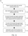
- US2019/045207 A1 discloses a portable electronic system comprising a sensor configured to capture three-dimensional (3D) information about objects in a physical world; an active memory; a local memory; a transceiver configured for communication over a computer network with remote memory; and a processor communicatively coupled to the sensor, the active memory, the local memory, and the transceiver, and configured to execute computer executable instructions to provide a 3D representation of a portion of the physical world based at least in part on the 3D information about the objects in the physical world, wherein the 3D representation of the portion of the physical world comprises a plurality of blocks, each block having values representing objects in a region of portion of the physical world at a point in time.
- the invention is directed to a portable electronic system according to claim 1.
- the invention is also directed to a method of operating a portable electronic system in an augmented reality system, according to claim 2.
- Described herein are methods and apparatus for creating and using a three-dimensional (3D) world reconstruction in an augmented reality (AR), mixed reality (MR), or virtual reality (VR) system.
- AR augmented reality
- MR mixed reality
- VR virtual reality
- the world reconstruction may be constructed from image and depth information about those physical surroundings that are collected with sensors that are part of the AR/MR/VR system.
- the world reconstruction may then be used by any of multiple components of such a system.
- the world reconstruction may be used by components that perform visual occlusion processing, compute physics-based interactions or perform environmental reasoning.
- computational resources may be reduced by simplifying the data representing the world reconstruction.
- a simpler representation may reduce resources for the processing, storage and/or management of that data as well as for its use.
- use of computational resources may be reduced by representing the physical world in blocks that may be stored and retrieved separately, but combined in a way that provides a realistic representation of the physical world.
- the blocks may be managed in memory to limit computational resources and may, in some embodiments, enable sharing of blocks across AR/MR/VR systems operating in the same physical space such that each AR/MR/VR system does less processing to construct a world reconstruction.
- blocks may be persisted across sessions of a portable user system in an AR/MR/VR system.
- blocks persisted from a prior session may be selectively used, reducing the time for the user system to have an adequate representation of the physical world while nonetheless enabling the system to render virtual content to a user in a realistic way that reflects interaction of the virtual content with the physical world.
- use of computational resources may be reduced by selecting from among different representations of the physical world when accessing information about the physical world.
- the world reconstruction may include information about the physical world captured from different sensors and/or stored in different formats. The data that is the simplest to consume or provide may be supplied to a component using the world reconstruction to render virtual objects. Where simpler data is unavailable, data acquired with a different sensor, which may generate a higher computation load, may be accessed.
- the world reconstruction may include a depth map collected with a depth sensor and a more fulsome representation of the 3D world, such as may be stored as a mesh computed from image information. Information about the physical world may be supplied to a component doing occlusion processing based on the depth map where it is available. Where there are holes in the depth map, information to fill those holes may be extracted from the mesh.
- the depth map may be "live," representing the physical world as captured by the depth sensor at the time the data is accessed.
- Techniques as described herein may be used together or separately with many types of devices and for many types of scenes, including wearable or portable devices with limited computations resources that provide an augmented reality scene.
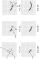
- FIGs. 1-2 illustrate such scenes.
- an AR system is used as an example of an XR system.
- FIGs. 3-8 illustrate an exemplary AR system, including one or more processors, memory, sensors and user interfaces that may operate according to the techniques described herein.
- an AR scene 4 is depicted wherein a user of an AR technology sees a physical world park-like setting 6, featuring people, trees, buildings in the background, and a concrete platform 8.
- the user of the AR technology also perceives that they "see” a robot statue 10 standing upon the physical world concrete platform 8, and a cartoon-like avatar character 2 flying by which seems to be a personification of a bumble bee, even though these elements (e.g., the avatar character 2, and the robot statue 10) do not exist in the physical world.
- Due to the extreme complexity of the human visual perception and nervous system it is challenging to produce an AR technology that facilitates a comfortable, natural-feeling, rich presentation of virtual image elements amongst other virtual or physical world imagery elements.
- Such an AR scene may be achieved with a system that include a world reconstruction component, which may build and update a representation of the physical world surfaces around the user. This representation may be used to occlude rendering, to place virtual objects, in physics based interactions, and for virtual character path planning and navigation, or for other operations in which information about the physical world is used.
- FIG. 2 depicts another example of an AR scene 200, showing exemplary world reconstruction use cases, including visual occlusion 202, physics-based interactions 204, and environment reasoning 206, according to some embodiments.
- the exemplary scene 200 is a living room having walls, a book shelf on one side of a wall, a floor lamp at a corner of the room, a floor, a sofa and coffee table on the floor.
- the user of the AR technology also perceives virtual objects such as images on the wall behind the sofa, birds flying through the door, a deer peeking out from the book shelf, and a decoration in the form of a windmill placed on the coffee table.
- the AR technology requires information about not only surfaces of the wall but also objects and surfaces in the room such as lamp shape, which are occluding the images to render the virtual objects correctly.
- the AR technology requires information about all the objects and surfaces around the room for rendering the birds with realistic physics to avoid the objects and surfaces or bounce off them if the birds collide.
- the AR technology requires information about the surfaces such as the floor or coffee table to compute where to place the deer.
- the system may identify that is an object separate from the table and may reason that it is movable, whereas corners of shelves or corners of the wall may be reasoned to be stationary. Such a distinction may be used in reasoning as to which portions of the scene are used or updated in each of various operations.
- a scene may be presented to the user via a system that includes multiple components, including a user interface that can stimulate one or more user senses, including sight sound and/or touch.
- the system may include one or more sensors that may measure parameters of the physical portions of the scene, including position and/or motion of the user within the physical portions of the scene.
- the system may include one or more computing devices, with associated computer hardware, such as memory. These components may be integrated into a single device or more be distributed across multiple interconnected devices. In some embodiments some or all of these components may be integrated into a wearable device.
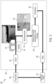
- FIG. 3 depicts an AR system 302 configured to provide an experience of AR contents interacting with a physical world 306, according to some embodiments.
- the AR system 302 may include a display 308.
- the display 308 may be worn by the user as part of a headset such that a user may wear the display over their eyes like a pair of goggles or glasses. At least a portion of the display may be transparent such that a user may observe a see-through reality 310.
- the see-through reality 310 may correspond to portions of the physical world 306 that are within a present viewpoint of the AR system 302, which may correspond to the viewpoint of the user in the case that the user is wearing a headset incorporating both the display and sensors of the AR system to acquire information about the physical world.
- AR contents may also be presented on the display 308, overlaid on the see-through reality 310.
- the AR system 302 may include sensors 322 configured to capture information about the physical world 306.
- the sensors 322 may include one or more depth sensors that output depth maps 312.
- Each depth map 312 may have multiple pixels, each of which may represent a distance to a surface in the physical world 306 in a particular direction relative to the depth sensor.
- Raw depth data may come from a depth sensor to create a depth map.
- Such depth maps may be updated as fast as the depth sensor can form a new image, which may be hundreds or thousands of times per second. However, that data may be noisy and incomplete, and have holes shown as black pixels on the illustrated depth map.
- the system may include other sensors, such as image sensors.
- the image sensors may acquire information that may be processed to represent the physical world in other ways.
- the images may be processed in world reconstruction component 316 to create a mesh, representing connected portions of objects in the physical world. Metadata about such objects, including for example, color and surface texture, may similarly be acquired with the sensors and stored as part of the world reconstruction.
- the system may also acquire information about the headpose of the user with respect to the physical world.
- sensors 310 may include inertial measurement units that may be used to compute and/or determine a headpose 314.
- a headpose 314 for a depth map may indicate a present viewpoint of a sensor capturing the depth map with six degrees of freedom (6DoF), for example, but the headpose 314 may be used for other purposes, such as to relate image information to a particular portion of the physical world or to relate the position of the display worn on the user's head to the physical world.
- the headpose information may be derived in other ways than from an IMU, such as from analyzing objects in an image.
- the world reconstruction component 316 may receive the depth maps 312 and headposes 314, and any other data from the sensors, and integrate that data into a reconstruction 318, which may at least appears to be a single, combined reconstruction.
- the reconstruction 318 may be more complete and less noisy than the sensor data.
- the world reconstruction component 316 may update the reconstruction 318 using spatial and temporal averaging of the sensor data from multiple viewpoints over time.
- the reconstruction 318 may include representations of the physical world in one or more data formats including, for example, voxels, meshes, planes, etc.
- the different formats may represent alternative representations of the same portions of the physical world or may represent different portions of the physical world.
- portions of the physical world are presented as a global surface; on the right side of the reconstruction 318, portions of the physical world are presented as meshes.
- the reconstruction 318 may be used for AR functions, such as producing a surface representation of the physical world for occlusion processing or physics-based processing. This surface representation may change as the user moves or objects in the physical world change. Aspects of the reconstruction 318 may be used, for example, by a component 320 that produces a changing global surface representation in world coordinates, which may be used by other components.
- the AR applications 304 may use this information to generate and update the AR contents.
- the virtual portion of the AR contents may be presented on the display 308 in combination with the see-through reality 310, creating a realistic user experience.
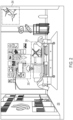
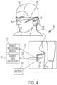
- the local data processing module 70 may include a processor, as well as digital memory, such as non-volatile memory (e.g., flash memory), both of which may be utilized to assist in the processing, caching, and storage of data.
- the data include data a) captured from sensors (which may be, e.g., operatively coupled to the frame 64) or otherwise attached to the user 60, such as image capture devices (such as cameras), microphones, inertial measurement units, accelerometers, compasses, GPS units, radio devices, and/or gyros; and/or b) acquired and/or processed using remote processing module 72 and/or remote data repository 74, possibly for passage to the display device 62 after such processing or retrieval.
- sensors which may be, e.g., operatively coupled to the frame 64
- image capture devices such as cameras
- microphones such as cameras
- inertial measurement units such as cameras
- accelerometers compasses
- GPS units GPS units
- radio devices radio devices
- the local data processing module 70 may include one or more processors (e.g., a graphics processing unit (GPU)) configured to analyze and process data and/or image information.
- the local data processing module 70 may include a single processor (e.g., a single-core or multi-core ARM processor), which would limit the module 70's compute budget but enable a more miniature device.
- the world reconstruction component 316 may use a compute budget less than a single ARM core to generate physical world representations in real-time on a non-predefined space such that the remaining compute budget of the single ARM core can be accessed for other uses such as, for example, extracting meshes.
- a model of the physical world is required so that characteristics of the virtual objects, which can be impacted by physical objects, including the shape, position, motion and visibility of the virtual object, can be correctly computed.
- the model may include the reconstruction of a physical world, for example, the reconstruction 318.
- That model may be created from data collected from sensors on a wearable device of the user. Though, in some embodiments, the model may be created from data collected by multiple users, which may be aggregated in a computing device remote from all of the users (and which may be "in the cloud”).
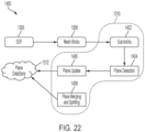
- the model may be created, at least in part, by a world reconstruction system, for example, the world reconstruction component 316 of FIG. 3 depicted in more detail in FIG. 6 .
- the world reconstruction component 316 may include a perception module 160 that may generate, update, and store representations for a portion of the physical world.
- the perception module 160 may represent the portion of the physical world within a reconstruction range of the sensors as multiple voxels. Each voxel may correspond to a 3D cube of a predetermined volume in the physical world, and include surface information, indicating whether there is a surface in the volume represented by the voxel.
- Voxels may be assigned values indicating whether their corresponding volumes have been determined to include surfaces of physical objects, determined to be empty or have not yet been measured with a sensor and so their value is unknown. It should be appreciated that values indicating that voxels that are determined to be empty or unknown need not be explicitly stored, as the values of voxels may be stored in computer memory in any suitable way, including storing no information for voxels that are determined to be empty or unknown.
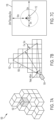
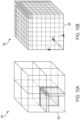
- FIG. 7A depicts an example of a 3D space 100 discretized into voxels 102.
- the perception module 160 may determine objects of interest and set the volume of a voxel in order to capture features of the objects of interest and avoid redundant information.
- the perception module 160 may be configured to identify larger objects and surfaces, such as walls, ceilings, floors, and large furniture. Accordingly, a volume of a voxel may be set to a relatively large size, for example, a cube of 4 cm 3 .
- the sensor 182 may be of any suitable type, such as a depth sensor. However, depth data may be derived from an image sensor(s) or in other ways.
- the perception module 160 may receive data from the sensor 182, and then set the values of multiple voxels 186 as illustrated in FIG. 8B to represent the portion 180 of the surface visible by the sensor 182 in the field of view 184.
- the sensor 182 may move to a second location and have a field of view 188.
- a further group of voxels become visible, and the values of these voxels may be set to indicate the location of the portion of the surface that has entered the field of view 188 of sensor 182.
- the values of these voxels may be added to the volumetric model for the surface
- the sensor 182 may further move to a third location and have a field of view 190.
- additional portions of the surface becomes visible in the field of view 190.
- a further group of voxels may become visible, and the values of these voxels may be set to indicate the location of the portion of the surface that has entered the field of view 190 of the sensor 182.
- the values of these voxels may be added to the volumetric model for the surface.
- this information may be stored as part of the persisted world as volumetric information 162a.
- Information about the surfaces may also be stored, such as color or texture. Such information may be stored, for example, as volumetric metadata 162b.
- the perception module 160 may identify and output indications of changes in a region around a user of a AR system. Indications of such changes may trigger updates to volumetric data stored as part of the persisted world, or trigger other functions, such as triggering components 304 that generate AR content to update the AR content.
- the perception module 160 may identify changes based on a signed distance function (SDF) model.
- the perception module 160 may be configured to receive sensor data such as, for example, depth maps 160a and headposes 160b, and then fuse the sensor data into a SDF model 160c.
- Depth maps 160a may provide SDF information directly, and images may be processed to arrive at SDF information.
- the SDF information represents distance from the sensors used to capture that information. As those sensors may be part of a wearable unit, the SDF information may represent the physical world from the perspective of wearable unit and therefore the perspective of the user.
- the headposes 160b may enable the SDF information to be related to a voxel in the physical world.
- the perception module 160 may generate, update, and store representations for the portion of the physical world that is within a perception range.
- the perception range may be determined based, at least in part, on a sensor's reconstruction range, which may be determined based, at least in part, on the limits of a sensor's observation range.
- an active depth sensor that operates using active IR pulses may be operate reliably over a range of distances, creating the observation range of the sensor, which may be from a few centimeters or tens of centimeters to a few meters.
- FIG. 7B depicts a reconstruction range with respect to a sensor 104 having a viewpoint 106.
- a reconstruction of 3D spaces within the viewpoint 106 may be built based on data captured by the sensor 104.
- the sensor 104 has an observation range of 40 cm to 5 m.
- a sensor's reconstruction range may be determined to be smaller than the observation range of the sensor because sensor outputs close to its observation limits may be more noisy, incomplete, and inaccurate.
- a corresponding reconstruction range may be set to be from 1 to 3 m, and data collected with the sensor indicating surfaces outside this range may not be used.
- the perception range may be larger than a sensor's reconstruction range. If components 164 that use data about the physical world require data about regions within the perception range that are outside the portions of the physical world that are within the current reconstruction range, that information may be provided from the persisted world 162. Accordingly, information about the physical world may be readily accessible by a query. In some examples, an API may be provided to respond to such a query, providing information about the current perception range of the user. Such technique may reduce time needed to access an existing reconstruction and provide an improved user experience.
- the perception range may be a 3D space corresponding to a bounding box centered around a user location.
- the portion of the physical world within the perception range which may be queriable by the components 164, may move with the user.
- FIG. 7C depicts a bounding box 110 centered around a location 112. It should be appreciated that the size of the bounding box 110 may be set to enclose a sensor's observation range with reasonable extensions because a user cannot move at an unreasonable speed. In the illustrated example, a sensor worn by the user has an observation limit of 5 m.
- the bounding box 110 is set as a cube of 20 m 3 .
- the world reconstruction component 316 may include additional modules that may interact with the perception module 160.
- a persisted world module 162 may receive representations for the physical world based on data acquired by the perception module 160.
- the persisted world module 162 also may include various formats of representations of the physical world. For example, volumetric metadata 162b such as voxels may be stored as well as meshes 162c and planes 162d. In some examples, other information, such as depth maps could be saved.
- these modules may operate on regions of the physical world, such as regions represented by blocks or tiles, as described below. Those modules may be triggered to update a block or tile, or other subregion of the physical world, when the perception module 160 detects a change in the physical world in that subregion. Such a change, for example, may be detected by detecting a new surface in the SDF model 160c or other criteria, such as changing the value of a sufficient number of voxels representing the subregion.
- the world reconstruction component 316 may include components 164 that may receive representations of the physical world from the perception module 160. Information about the physical world may be pulled by these components according to, for example, a use request from an application. In some examples, information may be pushed to the use components, such as via an indication of a change in a pre-identified region or a change of the physical world representation within the perception range.
- the components 164 may include, for example, game programs and other components that perform processing for visual occlusion, physics-based interactions, and environment reasoning.
- the perception module 160 may send representations for the physical world in one or more formats. For example, when the component 164 indicates that the use is for visual occlusion or physics-based interactions, the perception module 160 may send a representation of surfaces. When the component 164 indicates that the use is for environmental reasoning, the perception module 160 may send meshes, planes and semantics of the physical world.
- the perception module 160 may include components that format information to provide the component 164.
- An example of such a component may be raycasting component 160f.
- a use component e.g., component 164
- Raycasting component 160f may select from one or more representations of the physical world data within a field of view from that point of view.
- the depth image may have one or more pixels, each representing a distance to a surface in the scene. These distances can be related to a position relative to an image sensor, such that the data output from the image sensor may be selectively processed.
- Image data may be processed for those bricks representing portions of the 3D scene that contain surfaces that would be visible from the point of view (or "viewpoint") of the image sensor. Processing of some or all of the remaining bricks may be omitted.
- the selected bricks may be ones that are likely to contain new information, which may be arrived at by culling bricks about which the output of the image sensor is unlikely to provide useful information.
- the data output from the image sensor is unlikely to provide useful information about bricks that are either closer to or further from the image sensor than a surface indicated by the depth map because those bricks are either empty space or behind a surface and therefore not depicted in images from the image sensor.
- the culling/acceptance criteria may result in classifying some or all of the bricks accepted for further processing such that processing algorithms for the computationally volumetric reconstruction may be tailored for the characteristics of the brick.
- different processing may be selected based on whether the brick is classified as intersecting a surface, being in front of a solid surface or being in front of a holey surface.
- FIG. 9 shows a cross-sectional view of a scene 400 along a plane parallel to y-coordinate and z-coordinate.
- An XR system may represent the scene 400 by a grid of voxels 504.
- Conventional XR systems may update each voxel of the grid of voxels based on every new depth image captured by a sensor 406, which may be an image sensor or depth sensor, such that a 3D reconstruction generated from the grid of voxels can reflect changes in the scene. Updating in this fashion may consume significant computing resources and also cause artifacts at the output of an XR system due to, for example, time latency caused by heavy computing.
- the image sensor 406 captures a depth image (not shown) including a surface 402 of the scene 400.
- the depth image may be stored in computer memory in any convenient way that captures distance between some reference point and surfaces in the scene 400.
- the depth image may be represented as values in a plane parallel to an x-axis and y-axis, as illustrated in FIG. 9 , with the reference point being the origin of the coordinate system. Locations in the X-Y plane may correspond to directions relative to the reference point and values at those pixel locations may indicate distance from the reference point to the nearest surface in the direction indicated by the coordinate in the plane.
- Such a depth image may include a grid of pixels (not shown) in the plane parallel to the x-axis and y-axis.
- the reference point of the depth image may change. Such a configuration may allow the depth image to represent surfaces throughout an entire 3D scene, not limited to the portions having a predetermined and limited range of angles with respect to a particular point of reference.
- the depth image may indicate distance to surfaces as the image sensor 406 moves through six degree-of-freedom (6DOF) .
- the depth image may include a set of pixels for each of multiple reference points.
- a portion of the depth image may be selected based on a "camera pose," representing the direction and/or orientation in which the image sensor 406 is pointing at the time image data is captured.
- the image sensor 406 may have a field-of-view (FOV), which may be represented by the camera frustum 404.
- FOV field-of-view
- the infinite camera frustum depicted may be reduced to a finite 3D trapezoidal prism 408 by assuming a maximum depth 410 that the image sensor 406 can provide, and/or a minimum depth 412 that the image sensor 406 can provide.
- the 3D trapezoidal prism 408 may be a convex polyhedron delimited by at six planes.
- the method 600 may cull a portion of the one or more bricks against a camera frustum (e.g., the finite 3D trapezoidal prism 408 derived from the camera frustum 404) so as to produce a first one or more bricks, which is a reduced set of bricks from the one or more bricks.
- a camera frustum e.g., the finite 3D trapezoidal prism 408 derived from the camera frustum 404
- Such culling may eliminate bricks representing portions of the scene outside the field of view of the image sensor at the time image data being processed was acquired. That image data, therefore, is unlikely to contain information useful in creating or updating a brick.
- the method 600 may cull a portion of the first one or more bricks against the depth image so as to produce a second one or more bricks, which is a reduced set of bricks from the first one or more bricks.
- the method 600 may generate a 3D reconstruction of the scene based on the second one or more bricks.
- voxels between the image sensor 406 and the surface 402 may be empty.
- the degree of certainty may be represented by weight function, which weighs voxel updates based on the distance to the surface 402.
- weight function weighs voxel updates based on the distance to the surface 402.
- the voxel may get no update or a zero update (e.g., an update with zero changes).
- all voxels not falling into the camera frustum 404 may not be updated or investigated for this depth image.
- the method 600 may not only improve processing speed of volumetric depth image fusion, but also consume less memory storage, which allows the method 600 to run on wearable hardware. For example, a small reconstruction volume of 5m*5m*3m with 1 cm 3 voxel size and 8 bytes per voxel (4 bytes for the distance value and 4 bytes for the weight value) would already require about 600 MB.
- the method 600 can categorize bricks by their distance to a surface with respect to a truncated threshold. For example, the method 600 can identify empty bricks (e.g., the bricks that are culled, or the bricks that are away from the surface beyond the truncated threshold) so as to not allocate memory space for the empty bricks.
- the method 600 may allow flagging a brick during the voxel update as "does not contain any part of the surface," which can significantly speed up processing of a brick. That processing may include, for example, converting the image of the portion of the scene represented by a brick into a mesh.
- a desirable byproduct of this two-step test is that it may be known for each brick intersecting the camera frustum 404 whether it is completely or only partially inside the camera frustum 404. For the bricks completely inside the camera frustum 404, the test may be skipped for every voxel whether it lies inside the camera frustum 404 later at the individual voxel update.
- FIG. 14 shows an exemplary method 706 of conducting a camera frustum acceptance test, according to some examples.
- the method 706 may start by testing (act 802) each of the one or more sub-AABBs against each of planes delimiting the camera frustum 404.
- the method 706 may determine whether the tested sub-AABB is completely outside the camera frustum 404.
- the method 706 may cull all the bricks contained by this tested sub-AABB.
- the method 706 may determine whether the tested sub-AABB is completely inside the camera frustum 404.
- FIG. 15 shows an exemplary method 608 of culling a portion of the first one or more bricks against a depth image, according to some examples.
- the method 608 may start by conducting (act 902) a first depth image acceptance test for each of the first one or more bricks.
- the method 808 may determine whether a tested brick accepted by the first depth image acceptance test. If it is determined that the tested brick is accepted by the first depth image acceptance test, which may indicate the tested brick intersects with a surface in a scene, the method 608 may apply (act 906) varying increment to selected voxels, and add (act 914) the tested brick into the second one or more bricks.
- FIG. 16 shows an exemplary method 902 of conducting a first depth image acceptance test, according to some examples.
- the method 902 may start by determining (act 1002) a minimum brick value (bmin) and a maximum brick value (bmax) along a direction parallel to the z-coordinate.
- the bmin value and bmax value may be padded to account for an integration threshold, depth values beyond which indicate constant updates to voxels in a brick.
- the method 902 may compute 2D pixel positions of corners of the tested brick by projecting the corners of the brick into the depth image.
- the method 902 may compute a rectangle by building a convex hull of the 2D pixel positions of the corners of the brick.
- the method 902 may test each pixel in the rectangle against the bmin value and the bmax value.
- the method 902 may determine whether all pixels in the rectangle have a depth value between the bmin value and the bmax value. If it is determined that all the pixels in the rectangle have a depth value between the bmin value and the bmax value, the method 902 may accept (act 1012) the brick. If it is determined that not all the pixels in the rectangle have a depth value between the bmin value and the bmax value, the method 902 may conduct (act 908) a second depth image acceptance test for the brick.
- FIG. 17 shows an exemplary method 908 of conducting a second depth image acceptance test, according to some examples.
- the method 908 may start at act 1102 by categorizing all the pixels in the rectangle with respect to the bmin value and the bmax value.
- the method 908 may determine whether the tested brick is in front of a solid or holey background, for example, by using a table shown in FIG. 18 . If it is determined that the tested brick is in front of a solid or holey background, the method 908 may accept (act 1106) the brick. If it is determined that the tested brick is not in front of a solid or holey background, at act 916 the method 908 may cull the brick.
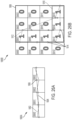
- FIGs. 19A-F depict an example of culling bricks representing a scene 190 against a camera frustum 192.
- the scene 190 is represented by a single AABB 194a, which includes 16x16 bricks in the illustrated example.
- the single AABB 194a is divided into four sub-AABBs 194b, each of which includes 8x8 bricks.
- a camera frustum acceptance test e.g., the method 706
- one of the four sub-AABBs 194b failed the camera frustum acceptance test and thus the 8x8 bricks in the failed sub-AABB 194b are culled and illustrated as white bricks.
- FIG. 1 the camera frustum acceptance test
- FIG. 20A depicts an example of further culling the 34 bricks 196f against a depth image including a surface 220 by conducting, for example, the method 608.
- FIG. 20B depicts the result of culling against the depth image, showing that 12 bricks 222a of the 34 bricks 196f passed the first depth image acceptance test (e.g., the method 904), 9 bricks 222b of the 34 bricks 196f passed the second depth image acceptance test (e.g., the method 910), and finally 13 bricks 222c of the 34 bricks 196f are culled after culling against the depth image comprising the surface 220.
- the first depth image acceptance test e.g., the method 904
- 9 bricks 222b of the 34 bricks 196f passed the second depth image acceptance test
- 13 bricks 222c of the 34 bricks 196f are culled after culling against the depth image comprising the surface 220.
- Geometries in a scene may be obtained in XR systems to support applications, for example, a wall to place a virtual screen, and/or a floor to navigate a virtual robot.
- a common representation of a scene's geometry is a mesh, which may comprise groups of connected triangles having vertices and edges.
- a geometry in a scene is obtained by generating a mesh for the scene and searching the geometry in the mesh, which takes time to process, e.g., a few seconds, and doesn't indicate relationships among geometries requested by different queries.
- a first query may be for a table plane.
- a system may find a table plane and leave a watch on the table plane.
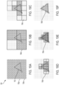
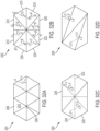
- FIG. 23 is a schematic diagram illustrating a scene 1500 represented by bricks [0000] - [0015] including voxels, and exemplary plane data including a brick plane 1502, global plane 1504, and surfel 1506 in the scene, according to some examples.
- FIG. 23 illustrates a brick [0011] being divided into four sub-brick 1508. It should be appreciated that a mesh brick may be divided into any suitable number of sub-bricks.
- the granularity of a plane detected by plane detection 1404 may be determined by the size of a sub-brick, while the size of a brick may be determined by the granularity of local/remote memories that stores the volumetric 3D reconstruction data.
- the plane detection 1404 may determine a brick plane (e.g., brick plane 1502) for each mesh brick based, at least in part, on the detected planes for each sub-bricks in the mesh brick.
- the plane detection 1404 may also determine global planes that extend more than one bricks (e.g., global plane 1504).
- plane extraction 1310 may further include plane merging and splitting 1408.
- the plane merging may merge multiple global planes into one big global plane, for example, when a brick plane is added and connects two global planes.
- Plane splitting may split one global plane into multiple global planes, for example, when a brick plane in the middle of a global plane is removed.
- FIG. 24 shows data structure in a plane data store 1312, according to some examples.
- Global planes 1614 indexed by plane IDs 1612 may be at the highest level of the data structure.
- Each global plane 1614 may include multiple brick planes and surfels of bricks adjacent to corresponding global planes, such that one brick plane may be persisted for each brick while a global plane can be accurately presented when edges of the global plane is not qualified as brick planes for corresponding bricks.
- surfels of bricks adjacent to a global plane are persisted instead of surfels of all bricks in a scene since it would be sufficient for accurately presenting a global plane.
- the global plane 1504 extends across brick [0008]-[0010] and [0006].
- the brick [0006] has the brick plane 1502, which is not part of the global plane 1504.
- the brick plane 1502 With the data structure in the plane data store 1312, when a plane query requests the global plane 1504, surfels of bricks [0006] and [0012] are checked to determine whether the global plane 1504 extends into the bricks [0006] and [0012]. In the illustrated example, surfels 1506 indicates that the global plane 1504 extends into the brick [0006].
- the global planes 1614 may be bi-directionally associated with corresponding brick planes 1610.
- Bricks may be identifiable by brick IDs 1602.
- Bricks may be divided into planar bricks 1604, which include at least one plane, and non-planar bricks 1606, which include no planes. Surfels for both planar bricks and non-planar bricks may be persisted, depending on whether a brick is adjacent a global plane but not whether the brick includes planes. It should be appreciated that planes may be continuously persisted in the plane data store 1312 while an XR system is observing a scene, regardless whether or not there is a plane query 1314.
- FIG. 25 shows planar geometry extraction 1702, which may extract planes for an application's usage, when the application sends the plane query 1314 to a plane data store 1312, according to some examples.
- the planar geometry extraction 1702 may be implemented as an API.
- the plane query 1314 may indicate requested planar geometry representation, for example, outer rectangular planes, inner rectangular planes, or polygon planes.
- plane search 1704 may search and obtain plane data in the plane data store 1312.
- rasterization from plane coverage points 1706 may generate plane coverage points.
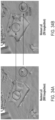
- An example is illustrated in FIG. 26A .
- Plane coverage points 1806 (or "rasterized points") are generated by projecting boundary points of the brick planes onto a global plane 1804.
- FIG. 26B An exemplary rasterized plane mask 1814 is illustrated in FIG. 26B .
- various planar geometry representations may be generated.
- a polygon 1812 is generated by connecting some of the plane coverage points of the rasterized plane mask such that none of the plane coverage pints in the mask is outside the polygon.
- An outer rectangle 1808 is generated such that the outer rectangle 1808 is the smallest rectangle surrounding the rasterized plane mask 1814.
- Inner rectangles 1810 are generated by assigning "1"s to bricks with two plane coverage points and "0"s to bricks without two plane coverage points to form a rasterized grid, determining groups of brick that are marked as "1" and aligned in a line parallel to an edge of a brick (e.g., bricks [0001], [0005], [0009], and [00013] as a group, bricks [0013]-[0015] as a group), and generating one inner rectangle for each determined group such that the inner rectangle is the smallest rectangle surrounding the respective group.
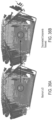
- FIG. 29 illustrated a less noisy 3D representation of the scene 1900, which is obtained by planarizing the mesh shown in FIG. 27 based on extracted plane data, for example, planes illustrated in FIGs. 28A-C .
- processing may be employed to reduce the complexity of a representation of an XR environment before that representation is stored or used in rendering functions, such as occlusion processing or computing physics of interactions among objects in the XR environment.
- meshing component 160d may simplify a mesh, or portion of a mesh, before storing it in persisted world 162 as a mesh 162c.
- Such processing may entail performing operations in stages on a representation of an XR environment. Those stages may include simplification operations that precede and follow a region-based operation.
- the region-based operation may, like the simplification operation, reduce the complexity of the representation of the XR environment.
- the total processing to produce a simplified representation of the XR environment may be reduced while maintaining the quality of the representation of the XR environment.
- a simplified high-quality representation may be updated frequently such that an XR environment may be frequently updated, improving the performance of the XR system, such as by presenting a more realistic environment to a user.
- a second simplification operation that follows the region-based operation may further simplify the representation of the environment, such as by further reducing the number of polygons in the representation.
- the second simplification operation may focus on reducing the number of polygons within each region detected by the region-based operation.
- three-dimensional (3D) mesh data is often used for multiple purposes including, for example, occluding virtual content in a graphics/game engine based on physical objects in the environment, or computing the effect rigid body collisions for virtual objects in a physics engine of a game engine.
- requirements for the mesh may differ for different uses of the mesh, and a simplified mesh may be suitable for many such uses, with some simplification techniques being better suited for some uses than others.
- Mesh simplification methods as described herein may provide real-time performance (e.g., low latency to support on the fly (real-time) environment changes), local update capability (e.g., renewing parts of a mesh that changed since last update), and planarized surfaces (e.g., flattened planar surfaces to support robust physics simulation).
- real-time performance e.g., low latency to support on the fly (real-time) environment changes
- local update capability e.g., renewing parts of a mesh that changed since last update
- planarized surfaces e.g., flattened planar surfaces to support robust physics simulation.
- a representation of an XR environment may be segmented into multiple blocks, some or all of which may be processed in parallel.
- the resulting blocks may then be recombined.
- the blocks may be defined with "skirts" that overlap adjacent blocks. The skirts enable recombination of the blocks with fewer and/or less noticeable discontinuities at the interfaces of the reassembled blocks.
- a mesh simplification method may include mesh block segmentation, pre-simplification, mesh planarization, and post-simplification.
- a global mesh may first be segmented into blocks of component meshes such that mesh blocks could be handled (e.g., processed) parallel. Then mesh blocks may be extended with skirts over boundaries between adjacent blocks. With skirted mesh blocks, simplification may be conducted on individual mesh block, while the global mesh may be visually seamless although topologically disconnected.
- a mesh simplification method may be suited for use by an application that uses the simplified mesh to represent interactions of objects in the XR environment, such as by making the simplification processing plane-aware.
- a three-step simplification process may be implemented.
- a mesh may be first pre-simplified moderately using a relatively high target triangle count.
- plane areas may be detected by a region growing algorithm.
- the mesh may be planarized by projecting corresponding triangles to the detected planes.
- the mesh may be regularized by adjusting plane (or primitive) normals to substantially vertical and parallel to the detected planes.
- a post-simplification process may be run over the planarized mesh.
- the post-simplification processing may focus more on the detected plane areas, for example, simplify the mesh of each detected plane area to reach a desired level of complexity (e.g., metric complexity), such as might be indicated by a target value of one or more metrics.
- a desired level of complexity e.g., metric complexity
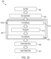
- FIG. 30 illustrates a method 3000 of generating a model of an environment represented by a mesh, according to some embodiments.
- the method 3000 may be performed on a meshing service on an XR platform.
- the method 3000 may start from an input mesh representing the environment at act 3002.
- the input mesh may have a high resolution, which may be indicated by the number of triangles.
- the input mesh may be generated by a reconstruction system (e.g., a volumetric 3D reconstruction system) and the input mesh may include 3D reconstruction data.
- a reconstruction system e.g., a volumetric 3D reconstruction system
- the reconstruction system may generate a volumetric 3D representation of the environment, which may create a data hierarchy of 3D information of the environment captured by one or more sensors.
- a sensor may be a depth camera, which may capture 3D information of the environment, for example, a stream of depth images with respective poses of the depth camera (i.e. camera poses).
- the 3D information of the environment may be processed into a voxel grid.
- Each voxel may contain one or more signed distance functions (SDFs) that describe whether the voxel lies inside or outside the geometries of objects in the environment.
- the voxels may be grouped into "bricks.”
- Each brick may include multiple voxels, for example, in cubic volumes such as 8 3 voxels.
- the bricks may be further grouped into "tiles.”
- Each tile may include multiple bricks.
- the size of a tile may be selected to facilitate memory operations in a computing device.
- the size may be selected based on the amount of information about the environment that is maintained in active memory of a device that is processing such data.
- the system may pass tiles between active memory, which is usually local to the device, and other memory that has more latency, such as non-volatile memory or remote memory in a cloud.
- One or more whole or partial tiles may contain information representing a "block" in a mesh or other representation of an environment.
- the volumetric 3D reconstruction system may generate the input mesh 3002 as a topologically-connected global mesh. In some embodiments, the volumetric 3D reconstruction system may generate the input mesh 3002 as a global mesh that is visually seamless although topologically-disconnected. For example, a topologically-disconnected global mesh may be comprised of multiple mesh blocks, each of which is generated from a block.
- a reconstruction system may be configured to capture substantial detail of an environment, which enables the system to distinguish between adjacent portions of the representation that have relatively small differences in their characteristics. Adjacent regions of different properties may be identified as different surfaces, resulting in the system identifying a large number of surfaces in the environment. However, such a system may capture details that are unnecessary for many applications, but are nonetheless processed. For example, a reconstruction system may unnecessarily present bumps on a wall with many triangles when two triangles making a rectangle would be a sufficient representation of the wall for a client application requesting meshes from the meshing service.
- an application when requesting a mesh from the meshing service, may specify a target simplification level of the requested mesh. That target simplification level may be expressed as a degree of compression, a number of triangles per unit area, or in any other suitable way.
- the method 3000 may efficiently generate a model of the environment, which is sufficient for the client application, from the input mesh.
- the input mesh may be segmented into one or more first mesh blocks, each of which may correspond to a block in the data hierarchy of the volumetric 3D representation of the environment.
- Each first mesh block may represent a portion of the environment and may have a first value of a metric of complexity (e.g., mesh resolution).
- a metric of complexity of a mesh block indicates a number of triangles in the mesh block.
- processing may be performed on mesh blocks sequentially and/or in parallel. However, simplification processing as described herein may be applied to the entire mesh or any suitable portion (e.g., one or more mesh blocks).
- Act 3006 represents a sub-process that is performed on each of multiple mesh blocks.
- the sub-processing may be performed on multiple mesh blocks independently, such that the processing may be readily performed in parallel for some or all of the mesh blocks.
- the sub-process may be performed on all mesh blocks or a subset of the mesh blocks selected for further processing.
- the subset of the mesh blocks may be selected based, at least in part, on a field-of-view of a device on which an application requesting the simplified mesh is executing.
- some of the first mesh blocks may be selected based on, for example, objects described in the first mesh blocks or locations of the first mesh blocks.
- a multi-stage simplification may be performed for each of the selected first mesh blocks.
- the multi-stage simplifications on the selected first mesh blocks may be performed in parallel and, as a result, the simplifications on the selected first mesh blocks may be completed approximately at a same point of time, though this may depend on the metric of complexity of each mesh block of the selected first mesh blocks.
- the multi-stage simplification may include a pre-simplification operation, a region-based operation (e.g., a planarization operation), and a post-simplification operation.
- the multi-stage simplification may be performed based on an input value from the client application.
- the input value may indicate required mesh complexity by the client application (e.g., mesh resolution).
- the input value from the client application may be the same or different for each of the selected first mesh blocks.
- the target value may be provided in any suitable way.
- An instance of the method 3000 may be pre-configured with a target value.
- the target value may be supplied through an API by an application requesting a mesh from the meshing service performing the method 3000.
- the target value for act 3012 may be a final target requested by a rendering function (e.g., the requesting application).
- the target value provided as an input may be adjusted or overridden to ensure that sufficient data remains in the mesh for subsequent processing.
- processing in act 3014 may require a minimum number of triangles and a target value provided by an application may be replaced by that minimum value if the target value is below the minimum number of triangles.
- the pre-simplified mesh may have values of one or more metrics such that the pre-simplified mesh can be processed faster during the region-based operation than the original block segmented input mesh, while still containing all or most of the regions of the original block segmented input mesh.
- the simplified mesh may be too coarse, unevenly distributed, and/or lose many regions of the original block segmented input mesh that are required in the following region-based operation.
- the second mesh block produced in act 3012 may have a second value of the metric of complexity, which may be less than the first value of the metric complexity.
- the pre-simplification operation of act 3012 may be performed using a triangle reduction algorithm.
- the planarization operation may include detecting planar areas in the second mesh block, for example, using a region growing algorithm, projecting meshes of the detected planar areas to corresponding planes, adjusting plane normals of the detected planar areas to be substantially perpendicular to the corresponding planes, and simplifying the projected meshes on each of the corresponding planes based on, for example, a target triangle count.
- plane normals of the detected planar areas may be adjusted before projecting meshes of the detected planar areas to the corresponding planes.
- a post-simplification operation may be performed on the third mesh block to generate a fourth mesh block.
- processing at act 3014 may desirably be performed on a mesh with more resolution than is required in the simplified mesh that is to be output from method 3000.
- processing at act 3016 may simplify the entire mesh block to reach a desired level of complexity (e.g., metric complexity), such as might be indicated by a target value of one or more metrics, which may be the same or different target than was supplied to act 3012.
- the post-simplification operation at act 3016 may focus on reducing the number of polygons within each plane detected by the planarization operation at act 3014.
- the fourth mesh block may have a fourth value of the metric of complexity, which may be less than the third value of the metric complexity.
- a percentage reduction between the third value of the metric complexity and the fourth value of the metric complexity may be greater than a percentage reduction between the first value of the metric complexity and the second value of the metric complexity.
- the percentage reduction between the third value of the metric complexity and the fourth value of the metric complexity may be at least two times greater than the percentage reduction between the first value of the metric complexity and the second value of the metric complexity.
- the post-simplification operation of act 3016 may be performed using a triangle reduction algorithm.
- the post-simplification operation of act 3016 may be performed using the same simplification algorithm as the pre-simplification operation of act 3012.
- these techniques may be used in an AR and/or a MR "platform," which receives and processes data from sensors worn by one or more users.
- This sensor data may be used to create and update 3D reconstruction data, representative of portions of the physical world encountered by the user(s).
- a reconstruction service may continually reconstruct a 3D representation of the physical world when the sensors are capturing and updating data.
- One or more techniques may be used to determine the blocks impacted by changes in the physical world and those blocks may be updated.
- This 3D reconstruction data may then be provided to applications that use the 3D reconstruction data to render scenes to depict virtual reality objects positioned in or interacting with objects in the physical world.
- This data may be provided to applications through an application programming interface (API).
- the API may be a push or pull interface, either pushing data to the application when relevant portions change or responding to a request from the application for up-to-date information.
- an application e.g., graphics/game engine
- its internal block e.g., block stored in active memory and/or local cache
- a reconstruction service may know which blocks the application has, and can therefore calculate which other (e.g., neighboring) blocks need to be updated in the engine to maintain correct overlap with the skirt/zipper as the in-view blocks update.
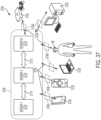
- Servers 3710 each include, for example, working memory and storage for storing data and software programs, microprocessors for executing program instructions, graphics processors and other special processors for rendering and generating graphics, images, video, audio and multi-media files.
- Computing network 3705 may also include devices for storing data that is accessed, used or created by the servers 3710.
- computing network 3705 may include remote processing module 72 and remote data repository 74.
- a digital world is represented by data and processes that describe and/or define virtual, non-existent entities, environments, and conditions that can be presented to a user through the device 3720 for users to experience and interact with.
- some type of object, entity or item that will appear to be physically present when instantiated in a scene being viewed or experienced by a user may include a description of its appearance, its behavior, how a user is permitted to interact with it, and other characteristics.
- Data used to create an environment of a virtual world may include, for example, atmospheric data, terrain data, weather data, temperature data, location data, and other data used to define and/or describe a virtual environment. Additionally, data defining various conditions that govern the operation of a virtual world may include, for example, laws of physics, time, spatial relationships and other data that may be used to define and/or create various conditions that govern the operation of a virtual world (including virtual objects).
- the entity, object, condition, characteristic, behavior or other feature of a digital world will be generically referred to herein, unless the context indicates otherwise, as an object (e.g., digital object, virtual object, rendered physical object, etc.).
- Objects may be any type of animate or inanimate object, including but not limited to, buildings, plants, vehicles, people, animals, creatures, machines, data, video, text, pictures, and other users. Objects may also be defined in a digital world for storing information about items, behaviors, or conditions actually present in the physical world.
- the data that describes or defines the entity, object or item, or that stores its current state, is generally referred to herein as object data. This data is processed by the servers 3710 or, depending on the implementation, by a gateway 3740 or the device 3720, to instantiate an instance of the object and render the object in an appropriate manner for the user to experience through the device 3720.
- a digital world Programmers who develop and/or curate a digital world create or define objects, and the conditions under which they are instantiated. However, a digital world can allow for others to create or modify objects. Once an object is instantiated, the state of the object may be permitted to be altered, controlled or manipulated by one or more users experiencing a digital world.
- development, production, and administration of a digital world is generally provided by one or more system administrative programmers.
- this may include development, design, and/or execution of story lines, themes, and events in the digital worlds as well as distribution of narratives through various forms of events and media such as, for example, film, digital, network, mobile, augmented reality, and live entertainment.
- the system administrative programmers may also handle technical administration, moderation, and curation of the digital worlds and user communities associated therewith, as well as other tasks typically performed by network administrative personnel.
- the device 3720 Users interact with one or more digital worlds using some type of a local computing device, which is generally designated as the device 3720.
- a local computing device which is generally designated as the device 3720.
- the device 3720 may include, or communicate with, local peripheral or input/output components such as, for example, a keyboard, mouse, joystick, gaming controller, haptic interface device, motion capture controller, audio equipment, voice equipment, projector system, 3D display, and holographic 3D contact lens.
- FIG. 38 is a schematic diagram, illustrating an electronic system 3800, according to some embodiments.
- the system 3800 may be a part of the system 3700 of FIG. 37 .
- the system 3800 may include a first device 3810 (e.g., a first portable device of a first user) and a second device 3820 (e.g., a second portable device of a second user).
- the devices 3810 and 3820 may be the devices 3720 and AR display system 80 of FIG. 37 .
- the devices 3810 and 3820 may communicate with a cloud cache 3802 through networks 3804a and 3804b, respectively.
- the cloud cache 3802 may be implemented in a memory of one or more servers 3710 of FIG. 37 .
- the networks 3804a and 3804b may be an example of data network 3730 and/or local gateway 3740 of FIG. 37 .
- the devices 3810 and 3820 may be individual AR systems (e.g., the devices 3720). In some embodiments, the devices 3810 and 3820 may include AR display systems worn by their respective users. In some embodiments, one of the devices 3810 and 3820 may be an AR display system worn by a user; the other may be a smartphone held by a user. Although two devices 3810 and 3820 are illustrated in the example, it should be appreciated that system 3800 may include one or more devices, and the one or more devices may be operating the same type of AR systems or different types of AR systems.
- the devices 3810 and 3820 may be portable computing devices.
- the first device 3810 may include a processor 3812, a local cache 3814, and one or more AR applications 3816.
- the processor 3812 may include a computing portion 3812a configured to execute computer executable instructions to provide a 3D representation (e.g., 3D reconstruction data) of a portion of a physical world based at least in part on data collected with one or more sensors (e.g., depth sensor 51, world camera 52, and/or inertial measurement units 57 of FIG. 3B).
- a 3D representation e.g., 3D reconstruction data
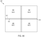
- the computing portion 3812a may represent the physical world as one or more blocks. Each block may represent objects in a different region of the physical world. Each region may have a corresponding volume. In some embodiments, the blocks may represent regions with a same volume. In some embodiments, the blocks may represent regions with different volumes. For example, when the physical world is an office room, the office room may be divided into cubes, each of which may be one cubic foot. One block may include a 3D representation (e.g., 3D reconstruction data) of one cube of the office room. In some embodiments, the office room may be divided into regions with various volumes, and each volume may include a similar amount of 3D information (e.g., 3D reconstruction data) such that the data size of a 3D representation of each region may be similar.
- 3D representation e.g., 3D reconstruction data
- Each block may have one or more versions, with each version containing data (e.g., volumetric 3D reconstruction data such as voxels, and/or mesh that may represent surfaces in a region represented by a respective block) representing its corresponding region based on data from a point in time.
- the computing portion 3812a may create new versions of a block as additional data becomes available, such as data indicating that objects in the physical world have changed or additional data from which a more accurate representation of the physical world may be created.
- Additional data may come from sensors on the device (e.g., the device 3810 and/or 3820). In some embodiments, additional data may come from remote sensors, and may be obtained, for example, over a network connection.
- the cloud cache (e.g., remote cache) 3802, accessed through the network 3804a, is an example of a remote cache.
- the processor 3812 may manage when blocks are moved between the local cache 3814 and the cloud cache 3802. For example, when the local cache 3814 is full, the processor 3812 may page out blocks to the cloud cache 3802 through the network 3804a. As blocks in the local cache 3814 are accessible for rendering a scene with lower latency than blocks in a cloud cache, the processor 3812 may select blocks to be paged out of the local cache 3814 using an algorithm intended to keep in the local cache 3814 blocks most likely to become active. Such an algorithm may be based on time of access. In some embodiments, the algorithm may be based on a prediction of motion of the device that will change the field of view of the device.
- Applications that render scenes may obtain information representing the portions of the physical world that impact the scene to be rendered.
- An application 3816 may obtain active blocks from the active memory 3812b through a local gateway 3818a.
- the local gateway 3818a may be implemented as an application programming interface (API), such that the processor 3812 implements a "service" for the application 3816.
- API application programming interface
- the API may be implemented as a push or a pull interface, or may have attributes of both.
- the application 3816 may indicate portions of the physical world for which it requires data and the service may supply data of those portions.
- the service may supply data about portions of the physical world when such data changes or becomes available.
- the portions of the physical world about which data is supplied may be limited to portions that an application 3816 has indicated are relevant, such as data within the field of view of the device or data representing portions of the physical world that is within a threshold distance of the field of view of the device.
- the application 3816 may request data for a portion of the physical world and the service may supply data on the requested portion plus any adjacent portions in which data has changed.
- the service may, in addition to maintaining the blocks that described the physical world, track which versions of the blocks were provided to each of the applications 3816.
- the operations to determine which portion of a representation of a physical world is to be updated and where that update occurs may be partitioned between applications 3816 and a service in any suitable way. Similarly, where updated data is incorporated into a representation of the physical world can be partitioned in any suitable ways.
- an application 3816 may operate on a mesh representation of a portion of the physical world constituting a 45 degree viewing angle for a distance of 10 meters relative to an origin defined by a current location of a device and a direction in which the device is facing. As this region changes or data indicates physical changes within this region becomes available, a mesh may be computed to represent this area. That mesh may be computed in the application 3816 based on data supplied by the service or may be computed in the service and provided to the application 3816. In either case, the service may store information in the physical world simplifying computation of the mesh.
- Blocks with zippers, skirts or implemented with other techniques to facilitate "papering over” cracks between adjacent blocks, as described herein, may be used so as to enable processing of only changed portions of the representation of the physical world.
- the changed portions of the representation of the physical world may then replace corresponding portions in a previous representation of the physical world.
- gateway 3818a is a pull interface.
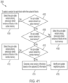
- the processor 3812 may search blocks persisted in the local cache 3814. If the processor 3812 cannot find a block in both the active memory 3812b and the local cache 3814, the processor 3812 may search blocks persisted in the cloud cache 3802.
- the processor may provide information based on the selected versions of blocks to the application. Processing at act 3910 may entail simply providing the blocks to the application, which may be appropriate when the application uses blocks directly. Where the application receives a mesh, processing at act 3910 may entail generating a mesh from the blocks and/or the subset of blocks, and providing the mesh, or any suitable portion of the mesh, to the application.
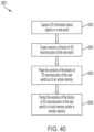
- a processor e.g., processor 3812 or 3822 of the system may create versions of blocks including 3D reconstruction data of the physical world based on the 3D information captured by the one or more sensors.
- each block may be formatted as one or more portions of a mesh.
- other representations of the physical world may be used.
- the blocks may have versions, such that each time information about a region of the physical world is captured by any device, a new version of the block may be stored.
- Each version of the block may have 3D reconstruction data including values representing objects in a region of the physical world at a point in time.
- processing may be performed locally on the device, resulting in new versions of blocks being stored in active memory.
- similar processing may be performed in a server (e.g., server 3710 of FIG. 37 ), which may manage versions of the blocks such that the most recent version of each block available in its remote cache is supplied when requested by any device.
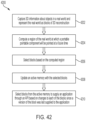
- a new version of a block may not necessarily be created when new 3D reconstruction data representing the corresponding region of the physical world is available. Rather, managing versions of the blocks may entail processing of the 3D reconstruction data representing the physical world to determine whether there have been sufficient changes since the last version of the blocks representing those regions of the physical world to warrant changes. In some examples, sufficient changes may be indicated by a magnitude of a block metric becoming above a threshold value since the last version has been stored.
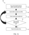
- One or more techniques may be used to manage the versions of a block available to a service on each device. If, for example, there is an acceptable version of the block already computed, rather than create a new version of the block from the sensor data, a processor may access a previously stored block. Such access may be performed efficiently by managing the storage of versions of the blocks.
- the processor of the device may page the versions of the blocks of 3D reconstruction data of the physical world out of an active memory (e.g., active memory 3812b or 3822b).
- the paging may include the processor accessing sensor data so as to continuously update the blocks in active memory/local cache/cloud cache, for example, as a function of the field of view of that device.
- blocks corresponding to the new field of view may be transferred (e.g., paged) from the local cache and/or the cloud cache into the active memory, and blocks corresponding to areas just outside the new field of view (e.g., blocks adjacent to the blocks in the new field of view) may be transferred (e.g., paged) from the active memory and/or the cloud cache to the local cache.
- the versions of the blocks paged out by the processor may be persisted in a local memory (e.g., local cache 3814 or 3824) and/or a remote memory (e.g., cloud cache 3802).
- a remote memory e.g., cloud cache 3802
- FIG. 41 is a flow chart illustrating an exemplary process for performing selecting versions of blocks representing a subset of blocks, according to some examples.
- FIG. 41 is a flow chart illustrating details of act 3908 of FIG. 39 .
- a processor e.g., processor 3812 or 3822
- processing proceeds to act 4104, where the up-to-date version is selected. If no up-to-date version is stored in the active memory, processing proceeds to act 4106, where the processor may query whether an up-to-date version is stored in a local memory (e.g., local cache 3814 or 3824). That query may be performed using criteria described above as in connection with act 4102, or any other suitable criteria. If an up-to-date version is stored in the local memory, at act 4108, the up-to-date version is selected.
- a local memory e.g., local cache 3814 or 3824
- the processor may query whether an up-to-date version is stored in a remote memory (e.g., cloud cache 3802). That query also may be performed using criteria described above as in connection with act 4102, or any other suitable criteria. If an up-to-date version is stored in the remote memory, at act 4112, the up-to-date version is selected.
- a remote memory e.g., cloud cache 3802
- FIG. 42 is a flow chart, illustrating a method 4200 of operating a system, according to some examples.
- paging may be managed based on projections of the field of view of the device based on device motion.
- sensors on a device may capture 3D information about a physical world including objects in the physical world and represent the physical world as blocks including 3D reconstruction data.
- a processor may compute, based at least in part on an output of the sensor, a region of the physical world at which a portable pointable component (e.g., depth sensor 51, world camera 52, and/or inertial measurement units 57) will be pointed at a future time.
- the processor may compute based on motion data from inertial sensors or analysis results of captured images. In a simple calculation, for example, to get a fast result, the processor may compute based on translation and rotation of the head of a user.
- the processor may compute based on objects in the scene. For example, the algorithms may consider a user walking towards a wall or table is unlikely to walk through the wall or table.
- the processor may select blocks based on the computed region.
- the processor may update an active memory (e.g., active memory 3812b or 3822b) with the selected blocks.
- the processor may select blocks based on the flow chart of FIG. 41 .
- the processor may select blocks from the active memory to supply an application (e.g., application 3816 or 3826), for example, through an API, based on changes to each of the blocks since a version of the block was last supplied to the application.
- a device may communicate with a cloud service that shares blocks with multiple devices to determine the latest version of a block representing a portion of the physical world. If the device has persisted the latest version of the block, it may continue to use it.
- a time stamp reflecting the time of creation of the block, may be used. For example, a persisted block may be used when its time stamp is less than a threshold amount of time prior to the current time.
- Block-based processing as described above may be based on blocks that allow portions of a 3D representation to be processed separately and then combined with other blocks.
- the blocks may be formatted such that, when a block is changed, the changed representation largely or wholly maintains the values of the block at the interfaces to other blocks.
- Such processing enables the changed version of a block to be used with versions of adjacent blocks that were not changed, without creating unacceptable artifacts in a scene rendered based on changed and unchanged blocks.
- FIGs. 43A-48 illustrate such blocks.
- a 3D representation of a physical world may be provided by a volumetric 3D reconstruction, which may create a 3D reconstruction data hierarchy of 3D information of the physical world captured by a sensor.
- the sensor may be a depth camera, which may capture 3D information of the physical world, for example, a stream of depth images with respective poses of the depth camera (i.e. camera poses).
- the 3D information of the physical world may be processed into a voxel grid.
- Each voxel may contain one or more signed distance functions (SDFs) that describe whether the voxel lies inside or outside the geometries of objects in the physical world.
- the voxels may be grouped into "bricks.”
- Each brick may include multiple voxels, for example, in cubic volumes such as 8 3 voxels.
- the bricks may be further grouped into "tiles.”
- Each tile may include multiple bricks.
- the voxel grid may be mapped to conform to a memory structure.
- a tile may correspond to a memory page of a storage medium.
- the size of a tile may be variable, for example, depending on the size of a memory page of a storage medium in use.
- the 3D reconstruction data may be transmitted among storage mediums (e.g., an active memory and/or local memory of a device, and/or a remote memory in a cloud), on the basis of tiles.
- one or more tiles may be processed to generate a block.
- a block may be updated, for example, when at least one voxel in the one or more tiles changes.
- a block may not necessarily be limited to corresponding to tiles.
- a block may be generated from one or more bricks, one or more voxels, or one or more SDF samples, and the like.
- a block may be any suitable partition of a physical world.
- a block may not necessarily limited to be in the format of a mesh.
- a block may be in any suitable format of 3D reconstruction data.
- FIG. 43B is a simplified schematic diagram illustrating a mesh block, according to some examples.
- a mesh block internally may have a fully connected mesh, which means that vertices are shared by multiple triangles.
- FIG. 43C is a simplified schematic diagram illustrating a crack, which may exist at edges of two adjacent mesh blocks, according to some examples.
- FIG. 44D is a simplified schematic diagram illustrating the crack in FIG. 43C being papered over by implementing mesh skirts that overlap an adjacent mesh blocks, according to some examples.
- FIG. 44 is a schematic diagram, illustrating in 2D segmenting a representation 4400 of a portion of a physical world, according to some examples.
- the 2D representation 4400 may be obtained by connecting a set of four blocks: Blocks A-D.
- the representation 4400 may be segmented into four blocks: Blocks 4402, 4404, 4406, and 4408, for example, illustrated by solid lines 4410.
- Blocks 4402, 4404, 4406, and 4408 may be designated as Blocks A-D respectively.
- Applications may desire 3D reconstruction data in the format of meshes for further processing such as occlusion testing, and generating physical effects in physical engines.
- the set of blocks may be in the format of meshes, which may be generated by a device (e.g., the devices 3810, 3820), a network (e.g., a cloud that includes cloud cache 3802), or a discrete application (e.g., the applications 3816, 3826).
- a device e.g., the devices 3810, 3820
- a network e.g., a cloud that includes cloud cache 3802
- a discrete application e.g., the applications 3816, 3826.
- regions at the boundaries of Blocks 4402, 4404, 4406, and 4408 may be skirts, for example, illustrated by dashed lines 4412.
- each of Blocks A-D may include a block and a corresponding skirt.
- Block B may include Block 4404 and a skirt 4414 that overlaps with boundary parts of Block B's neighboring blocks A, C, and D such that cracks between the blocks may be papered over when the blocks are connected into a global mesh.
- Blocks A, C, and D may also include corresponding skirts. Accordingly before returning blocks including 3D reconstruction data to an application, a processor may paper over any cracks between the blocks.
- the global mesh may be a topologically-connected global mesh.
- adjacent blocks in the set of blocks may share mesh vertices at block boundaries such as lines 4410.
- the global mesh may be visually seamless although topologically-disconnected using any suitable techniques such as skirts and zippers.
- 3D representation 4500 includes versions of Blocks A-H: version 4502 of Block A, version 4504 of Block B, version 4514 of Block C, version 4512 of Block D, version 4534 of Block E, version 4506 of Block F, version 4508 of Block G, and version 4510 of Block H.
- FIG. 46 is a schematic diagram, illustrating a 3D representation 4600 of a portion of a physical world obtained by updating the 3D representation 4500, according to some examples.
- 3D representation 4600 may have a new version 4610 of Block H that includes information 4630.
- Information 4630 may be different from information 4530.
- a first device may persist version 4510 of Block H in a remote memory.
- Version 4510 of Block H may include information 4530 corresponding to a table with an empty surface.
- a second device may place a virtual and/or physical box on the table's surface and then persist version 4610 of Block H in the remote memory.
- FIG. 47 is a schematic diagram, illustrating an augmented world 4700 viewable by a first device 4702 (e.g., device 3810) and a second device 4712 (e.g., device 3820).
- First and second devices may include AR display systems 4704 and 4714 (e.g., AR display system 80) operating in an augmented mode.
- An augmented world 4700 may be obtained by connecting four blocks: Blocks A-D.
- the augmented world 4700 includes versions of Blocks A-D: version 4702A of Block A, version 4702B of Block B, version 4702C of Block C, and version 4702D of Block D.
- the first device 4702 may be looking at a first direction 4706 and have a first field of view (FOV) 4708.
- FOV first field of view
- the processor of the first device 4702 may include computer-executable instructions for determining which of versions 4702C, 4802C, 4702D, and 4802D to provide to an application based on, for example, the change of FOV and/or information collected with a sensor of the first device 4702.
- the processor of the first device 4702 may include computer executable instructions for generating version 4802C of Block C and version 4802D of Block D when there are no corresponding up-to-date versions of Blocks C and D in a local memory (e.g., local cache 3814, 3824) or a remote memory (e.g., cloud cache 3802).
- the realism with which AR and MR scenes are presented to a user may be enhanced by providing occlusion data to applications generating such scenes, where the occlusion data is derived from a combination of one or more depth data sources.
- the occlusion data may represent surfaces of physical objects in the scene and may be formatted in any suitable way, such as by depth data indicating a distance from a point of view from which the scene is to be rendered and a surface.
- use components 164 may receive occlusion data from perception module 160 ( FIG. 6 ).
- one data source may be one or more depth cameras that directly sense and capture position between the depth cameras and real objects in a physical world. Data from depth cameras may be provided directly to use components 164 or may be provided indirectly, such as through perception module 160.
- the one or more depth cameras may provide an immediate view of the physical world at frame rate that is sufficiently high to capture changes in the physical world, but low enough not to burden processing.
- the frame rate may be 5 frames per second, 10 frames per second, 12 frames per second, 15 frames per second, 20 frames per second, 24 frames per second, 30 frames per second, and the like.
- the frame rate may be less than 5 frames per second.
- the frame rate may be more than 30 frames per second. Accordingly, in some examples, the frame rate may be in the range of 1-5 frames per second, 5-10 frames per second, 10-15 frames per second, 15-20 frames per second, or 20-30 frames per second, and the like.
- the system may include a filter that identifies which portions of a 3D region are represented by data from each of multiple depth data sources.
- the filter may apply one or more criteria to identify portions of the region, for which data from a second data source is to be collected. These criteria may be indications of the reliability of the depth data. Another criteria may be changes detected in the portion of the region since depth data was collected.
- Selecting between multiple depth data sources to provide data for different portions of a representation of a 3D region may reduce processing time. For example, when less processing is required to derive occlusion data from data collected with the first data source than with a second data source, the selection may favor data from the first data source, but use data from the second source when data from the first source is not available or acceptable.
- the first data source may be a depth camera and the second data source may be a stereoscopic visual camera.
- the data from the stereoscopic camera may be formatted as a 3D reconstruction of the physical world.
- the 3D reconstruction may be computed before occlusion data is required. Alternatively, or additionally, the 3D reconstruction may be re-computed when occlusion data is required. In some examples, criteria may be applied to determine whether the 3D reconstruction should be recomputed.
- this occlusion data is computed by a service, providing occlusion data through an application programming interface (API) to applications executing on a computing device that will render XR scenes.
- the service may execute on the same computing device as the applications or may execute on a remote computer.
- the service may include one or more of the components discussed herein, such as the filter for data from a first data source, and/or an engine to selectively fetch data from a second data source based on the filtered data from the first data source.
- the service may also include a component to combine the filtered data from the first data source and the selected data from the second data source to generate occlusion data.
- the occlusion data may be formatted in any suitable way that represents surfaces in the physical world.
- the occlusion data may be formatted as depth buffers of surfaces, storing data identifying locations of the surfaces in the physical world. This occlusion data may then be used in any suitable way.
- the occlusion data may be provided to one or more applications wanting to have virtual objects occluded by real objects.
- the occlusion data may be formatted as a depth filter created by the system for an application requesting an occlusion service for occlusion data for rendering virtual objects at one or more locations. The depth filter may identify locations for which the application should not render image information for the virtual object because virtual objects in those locations would be occluded by surfaces in the physical world.
- occlusion data may be in a suitable format to provide information about surfaces in the physical world and need not be used for occlusion processing. In some examples, occlusion data may be used in any application performing processing based on a representation of surfaces in a scene of the physical world.
- the mesh data may be obtained by processing geometrical data extracted by an image sensor with multiple time or cost intensive steps including, marching cube algorithms, mesh simplification, and applying triangle count limits.
- the mesh data may take from hundreds of milliseconds to seconds to calculate, and a delay in having an up-to-date mesh may lead to visible artifacts when the environment is dynamically changing and an application renders a scene using an outdated mesh.
- real-time depth maps of a physical environment may be obtained from depth sensors (e.g., depth cameras). Each pixel in a depth map may correspond to a discrete distance measurement captured from a 3D point in the environment. In some examples, these depth cameras may provide depth maps including a set of points at real-time rates. However, depth maps may have holes, which may result from the depth camera being unable to acquire sensor data representing a region or acquiring incorrect or unreliable data representing a region. In some examples, if the depth sensor uses infrared (IR) light, the holes may result, for example, from materials or structures in the physical environment that do not reflect IR light very well or at all.
- IR infrared
- the holes may result, for example, from very thin structures or surfaces at glancing incidence angles that do not reflect light toward the depth sensor.
- the depth sensor may also experience motion blur when moving fast, which may also lead to missing data.
- "holes" in the depth map represent regions of the depth map that for any other reason are not suitable for use in occlusion processing.
- Such holes may be detected using any suitable processing, such as processing the depth map to detect lack of connectivity between points or regions in the depth map.
- holes may be detected using processing that computes quality metrics for regions of the depth map and processing regions with low quality metrics as holes.
- One such metric may be image to image variation for pixels in a depth map representing the same location in the physical world. Pixels with such a variation exceeding a threshold may be classified as a hole.
- holes may be identified by pixels meeting predefined statistical criteria for a cluster of pixels in which the quality metric(s) is below a threshold.
- the rays may have a same pose an eye gaze of a user.
- the depth map may similarly be acquired with the same eye gaze of the user, because the depth sensor may be worn by the user, and it may be mounted on the user's head near the eyes.
- a visual camera used to form the 3D reconstruction data may similarly be worn by a user such that the images, and data derived from those images, may be related to a coordinate system that enables rays, defined with respect to the depth map, to be cast into the 3D reconstruction computed from the visual images.
- An inertial measurement unit and/or other sensors may provide data to perform coordinate transformations to add data to the 3D representation regardless of the pose of the visual camera and to relate rays, defined with respect to the depth map, to the 3D reconstruction.
- Processing as described above may be performed in hardware processors of many suitable forms on data acquired with many suitable sensors and presented on many suitable interfaces. Examples of suitable systems, including sensors, processing and user interfaces, are presented below.
- a "service" may be implemented as part of an XR system with computer executable instructions. Execution of those instructions may control one or more processors to access to sensor data and then generate and supply depth information to applications executing on the XR system. Those instructions may be executed on the same processor or same device that executes the application presenting XR scenes to a user or may be on a remote device, accessed by the user device over a computer network.
- the reconstruction filter 4902 may include computer executable instructions for producing a depth map based on the depth information 4904.
- the depth map may include one or more pixels. Each pixel may indicate a distance to a point of a surface in a physical world.
- the reconstruction filter 4902 may composite depth information 4904 and data from the raycast engine 4906.
- the reconstruction filter 4902 may reduce or remove noise from the depth information 4904 based, at least in part, on the data from the raycast engine 4902 and/or from the composite of the depth information 4904 and the data from the raycast engine 4906.
- the reconstruction filter 4902 may up-sample the depth information 4904 using deep-learning techniques.
Landscapes
- Engineering & Computer Science (AREA)
- Software Systems (AREA)
- Physics & Mathematics (AREA)
- Theoretical Computer Science (AREA)
- General Physics & Mathematics (AREA)
- Signal Processing (AREA)
- Multimedia (AREA)
- Computer Graphics (AREA)
- General Engineering & Computer Science (AREA)
- Geometry (AREA)
- Computer Security & Cryptography (AREA)
- Computer Hardware Design (AREA)
- Processing Or Creating Images (AREA)
- User Interface Of Digital Computer (AREA)
- Image Generation (AREA)
Claims (15)
- Ein tragbares elektronisches System (3810), umfassend:einen Sensor (51, 52), der konfiguriert ist, dreidimensionale (3D) Informationen über Objekte in einer physischen Welt zu erfassen;einen aktiven Speicher (3812b);einen lokalen Speicher (3814);einen Transceiver, der für die Kommunikation über ein Computernetzwerk (3804a) mit einem entfernten Speicher (3802) konfiguriert ist; undeinen Prozessor (3812), der mit dem Sensor (51, 52), dem aktiven Speicher (3812b), dem lokalen Speicher (3814) und dem Transceiver kommunikationsmäßig gekoppelt ist und konfiguriert ist, Computer ausführbare Anweisungen auszuführen, um eine 3D-Darstellung eines Teils der physischen Welt basierend zumindest teilweise auf den 3D-Informationen über die Objekte in der physischen Welt bereitzustellen, wobei:
die 3D-Darstellung des Teils der physischen Welt eine Vielzahl von Blöcken (3102, 3104, 3106, 23108) umfasst, wobei jeder Block Werte aufweist, die Objekte in einem Bereich des Teils der physischen Welt zu einem bestimmten Zeitpunkt darstellen, einschließlich Standortinformationen in Bezug auf die physische Welt; unddie Computer ausführbaren Anweisungen umfassen für:das Persistieren der Vielzahl von Blöcken (3102, 3104, 3106, 23108) in mindestens einem der aktiven Speicher (3812b), des lokalen Speichers (3814) und des entfernten Speichers (3802), wenn das tragbare elektronische System zu einem ersten Zeitpunkt in einen inaktiven Betriebsstatus wechselt;bei einem Übergang zu einem aktiven Status zu einem zweiten Zeitpunkt, nach dem ersten Zeitpunkt, das Auswählen von den persistierten Blöcken, die Teile der physischen Welt um das tragbare elektronische System (3810) zu dem zweiten Zeitpunkt darstellen; unddas Rendern, basierend zumindest teilweise auf den ausgewählten Blöcken, von virtuellen Inhalten für einen Benutzer des tragbaren elektronischen Systems (3810). - Ein Verfahren zum Betreiben eines tragbaren elektronischen Systems (3810) in einem erweiterten Realitätssystem, wobei das Verfahren umfasst:
mit mindestens einem Prozessor (3812):das Erhalten einer Vielzahl von Blöcken (3102, 3104, 3106, 23108), die dreidimensionale (3D) Informationen über Oberflächen in einer physischen Welt einschließlich Standortinformationen umfassen;das Speichern von mindestens einem der Vielzahl von Blöcken (3102, 3104, 3106, 23108) in einem aktiven Speicher (3812b);das Verwenden von Blöcken (3102, 3104, 3106, 23108) aus dem aktiven Speicher (3812b) zum Rendern von virtuellen Inhalten für einen Benutzer des tragbaren elektronischen Systems (3810);das Persistieren der Blöcke (3102, 3104, 3106, 23108) im aktiven Speicher (3812b) bei einem Übergang zu einem inaktiven Betriebsstatus zu einem ersten Zeitpunkt; undbei einem Übergang zu einem aktiven Betriebsstatus zu einem zweiten Zeitpunkt, nach dem ersten Zeitpunkt, das Auswählen von den persistierten Blöcken, die Teile der physischen Welt um das tragbare elektronische System (3810) zu dem zweiten Zeitpunkt darstellen; unddas Rendern, basierend zumindest teilweise auf den ausgewählten Blöcken, von virtuellen Inhalten für einen Benutzer des tragbaren elektronischen Systems (3810). - Das tragbare elektronische System (3810) nach Anspruch 1 oder das Verfahren nach Anspruch 2, wobei der inaktive Betriebsstatus Herunterfahren oder Schlafen ist und jeder Block (3102, 3104, 3106, 23108) eine volumetrische Darstellung des Bereichs des Teils der physischen Welt zu einem bestimmten Zeitpunkt umfasst.
- Das tragbare elektronische System (3810) nach Anspruch 3, wobei das Persistieren der Vielzahl von Blöcken (3102, 3104, 3106, 23108) in mindestens einem der aktiven Speicher (3812b), des lokalen Speichers (3814) und des entfernten Speichers (3802) umfasst,
wenn der inaktive Betriebsstatus Schlafen ist, das Persistieren der Vielzahl von Blöcken in den jeweiligen Speichern, in denen die Vielzahl von Blöcken derzeit existiert, sodass die Vielzahl von Blöcken vom tragbaren elektronischen System zugänglich ist, wenn das tragbare elektronische System aufwacht. - Das tragbare elektronische System (3810) nach Anspruch 3 oder Anspruch 4, wobei das Persistieren der Vielzahl von Blöcken (3102, 3104, 3106, 23108) in mindestens einem der aktiven Speicher (3812b), des lokalen Speichers (3814) und des entfernten Speichers (3802) umfasst,
wenn der inaktive Betriebsstatus Herunterfahren ist, das Persistieren von mindestens einem Teil der Blöcke im lokalen Speicher in den entfernten Speicher und das Persistieren von Blöcken im aktiven Speicher in den lokalen Speicher und/oder den entfernten Speicher. - Das tragbare elektronische System (3810) nach einem der Ansprüche 1 und 3-5, wobei die Computer ausführbaren Anweisungen umfassen für:das Berechnen eines oder mehrerer neuer Blöcke basierend zumindest teilweise auf eingehenden 3D-Informationen über Objekte in der physischen Welt unddas Auswählen von den persistierten Blöcken, die zumindest teilweise mit den ein oder mehreren neuen Blöcken überlappen, sodass persistierte Blöcke um das tragbare elektronische System abgerufen werden können.
- Das tragbare elektronische System (3810) nach Anspruch 6, wobei das Auswählen von den persistierten Blöcken, die Blöcke zumindest teilweise mit den ein oder mehreren neuen Blöcken überlappen, das Vergleichen der ein oder mehreren neuen Blöcke mit den persistierten Blöcken umfasst.
- Das tragbare elektronische System (3810) nach Anspruch 7, wobei das Vergleichen der ein oder mehreren neuen Blöcke mit den persistierten Blöcken das Vergleichen der ein oder mehreren neuen Blöcke mit Blöcken umfasst, die im aktiven Speicher persistiert sind.
- Das tragbare elektronische System (3810) nach Anspruch 8, wobei das Vergleichen der ein oder mehreren neuen Blöcke mit den persistierten Blöcken umfasst,
wenn der aktive Speicher keinen Block aufweist, der zumindest teilweise mit den ein oder mehreren neuen Blöcken überlappt, das Vergleichen der ein oder mehreren neuen Blöcke mit Blöcken, die im lokalen Speicher persistiert sind. - Das tragbare elektronische System (3810) nach Anspruch 9, wobei das Vergleichen der ein oder mehreren neuen Blöcke mit den persistierten Blöcken umfasst,
wenn der lokale Speicher keinen Block aufweist, der zumindest teilweise mit den ein oder mehreren neuen Blöcken überlappt, das Vergleichen der ein oder mehreren neuen Blöcke mit Blöcken, die im entfernten Speicher persistiert sind. - Das tragbare elektronische System (3810) nach Anspruch 6, wobei die Computer ausführbaren Anweisungen umfassen für:
das Aktualisieren der Vielzahl von Blöcken mit den ein oder mehreren neuen Blöcken. - Das tragbare elektronische System (3810) nach Anspruch 1 oder das Verfahren nach Anspruch 2, wobei die Blöcke Mesh-Blöcke sind und
die Vielzahl von Blöcken Räumen eines gleichen Volumens entspricht. - Das Verfahren nach einem der Ansprüche 2, 3 und 12, umfassend:
das Paging von Blöcken zwischen dem aktiven Speicher und einem lokalen Speicher basierend auf dem aktuellen oder projizierten Sichtfeld eines Benutzers des tragbaren elektronischen Systems. - Das Verfahren nach einem der Ansprüche 2, 3, 12 und 13, weiter umfassend, bei einem Übergang zu einem inaktiven Betriebsstatus, das Persistieren der Blöcke im lokalen Speicher.
- Das Verfahren nach einem der Ansprüche 2, 3 und 12-14, wobei das Verwenden von Blöcken aus dem aktiven Speicher zum Rendern von virtuellen Inhalten für den Benutzer das Verwenden der Blöcke für die visuelle Okklusionsverarbeitung und das Berechnen von physikbasierten Interaktionen und/oder Umweltüberlegungen umfasst.
Applications Claiming Priority (2)
| Application Number | Priority Date | Filing Date | Title |
|---|---|---|---|
| US201962850900P | 2019-05-21 | 2019-05-21 | |
| PCT/US2020/034068 WO2020237089A1 (en) | 2019-05-21 | 2020-05-21 | Caching and updating of dense 3d reconstruction data |
Publications (3)
| Publication Number | Publication Date |
|---|---|
| EP3973513A1 EP3973513A1 (de) | 2022-03-30 |
| EP3973513A4 EP3973513A4 (de) | 2023-06-28 |
| EP3973513B1 true EP3973513B1 (de) | 2025-04-09 |
Family
ID=73457250
Family Applications (1)
| Application Number | Title | Priority Date | Filing Date |
|---|---|---|---|
| EP20809014.2A Active EP3973513B1 (de) | 2019-05-21 | 2020-05-21 | Zwischenspeicherung und aktualisierung von dichten 3d-rekonstruktionsdaten |
Country Status (5)
| Country | Link |
|---|---|
| US (2) | US11302081B2 (de) |
| EP (1) | EP3973513B1 (de) |
| JP (1) | JP7636348B2 (de) |
| CN (1) | CN114245909B (de) |
| WO (1) | WO2020237089A1 (de) |
Families Citing this family (19)
| Publication number | Priority date | Publication date | Assignee | Title |
|---|---|---|---|---|
| US20200137380A1 (en) * | 2018-10-31 | 2020-04-30 | Intel Corporation | Multi-plane display image synthesis mechanism |
| EP3973513B1 (de) | 2019-05-21 | 2025-04-09 | Magic Leap, Inc. | Zwischenspeicherung und aktualisierung von dichten 3d-rekonstruktionsdaten |
| WO2020263471A1 (en) | 2019-06-26 | 2020-12-30 | Magic Leap, Inc. | Caching and updating of dense 3d reconstruction data |
| US11315326B2 (en) * | 2019-10-15 | 2022-04-26 | At&T Intellectual Property I, L.P. | Extended reality anchor caching based on viewport prediction |
| US11816757B1 (en) * | 2019-12-11 | 2023-11-14 | Meta Platforms Technologies, Llc | Device-side capture of data representative of an artificial reality environment |
| US11354867B2 (en) * | 2020-03-04 | 2022-06-07 | Apple Inc. | Environment application model |
| US12219118B1 (en) | 2021-03-10 | 2025-02-04 | Apple Inc. | Method and device for generating a 3D reconstruction of a scene with a hybrid camera rig |
| US11853100B2 (en) * | 2021-04-12 | 2023-12-26 | EMC IP Holding Company LLC | Automated delivery of cloud native application updates using one or more user-connection gateways |
| CN114237720B (zh) * | 2021-11-12 | 2025-01-07 | 深圳市普渡科技有限公司 | 深度相机的加载设备、装置、方法及存储介质 |
| US12062145B2 (en) * | 2022-02-01 | 2024-08-13 | Samsung Electronics Co., Ltd. | System and method for three-dimensional scene reconstruction and understanding in extended reality (XR) applications |
| US12423938B2 (en) | 2022-07-25 | 2025-09-23 | Dell Products L.P. | System and method for identifying auxiliary areas of interest for image based on focus indicators |
| US12288331B2 (en) | 2022-07-25 | 2025-04-29 | Dell Products L.P. | System and method for procedural reconstruction of synthesized images |
| US12249070B2 (en) * | 2022-07-25 | 2025-03-11 | Dell Products L.P. | System and method for image exploration using areas of interest |
| US12373955B2 (en) | 2022-07-25 | 2025-07-29 | Dell Products L.P. | System and method for storage management of images |
| US12361661B1 (en) | 2022-12-21 | 2025-07-15 | Meta Platforms Technologies, Llc | Artificial reality (XR) location-based displays and interactions |
| CN116524157B (zh) * | 2023-04-28 | 2024-05-14 | 神力视界(深圳)文化科技有限公司 | 扩展现实合成方法、装置、电子设备及存储介质 |
| US12353784B1 (en) * | 2024-03-04 | 2025-07-08 | Curio XR (VR EDU) | Modified views for an extended reality environment |
| CN118200510B (zh) * | 2024-04-08 | 2024-11-26 | 深圳职业技术大学 | 一种xr组合场景自动组合方法、系统及介质 |
| CN119006737B (zh) * | 2024-10-25 | 2024-12-20 | 江苏省地质测绘大队 | 基于地理空间边界约束的实景三维场景模型更新管理方法 |
Family Cites Families (46)
| Publication number | Priority date | Publication date | Assignee | Title |
|---|---|---|---|---|
| US5886702A (en) | 1996-10-16 | 1999-03-23 | Real-Time Geometry Corporation | System and method for computer modeling of 3D objects or surfaces by mesh constructions having optimal quality characteristics and dynamic resolution capabilities |
| US6879324B1 (en) | 1998-07-14 | 2005-04-12 | Microsoft Corporation | Regional progressive meshes |
| GB2386811B (en) * | 2000-12-18 | 2005-06-08 | Schlumberger Holdings | Method and apparatus for visualization of 3D voxel data using lit opacity volumes with shading |
| US7330528B2 (en) * | 2003-08-19 | 2008-02-12 | Agilent Technologies, Inc. | System and method for parallel image reconstruction of multiple depth layers of an object under inspection from radiographic images |
| US7644239B2 (en) * | 2004-05-03 | 2010-01-05 | Microsoft Corporation | Non-volatile memory cache performance improvement |
| US7961186B2 (en) | 2005-09-26 | 2011-06-14 | Siemens Medical Solutions Usa, Inc. | Brick-based fusion renderer |
| FR2897455A1 (fr) | 2006-02-13 | 2007-08-17 | Univ Hokkaido Nat Univ Corp | Dispositif, procede et programme de segmentation de donnees de modele en treillis |
| US20090225074A1 (en) * | 2008-03-06 | 2009-09-10 | Bates Cary L | Reconstruction of Virtual Environments Using Cached Data |
| US8774512B2 (en) | 2009-02-11 | 2014-07-08 | Thomson Licensing | Filling holes in depth maps |
| US8933925B2 (en) | 2009-06-15 | 2015-01-13 | Microsoft Corporation | Piecewise planar reconstruction of three-dimensional scenes |
| US8547374B1 (en) * | 2009-07-24 | 2013-10-01 | Lockheed Martin Corporation | Detection and reconstruction of 3D objects with passive imaging sensors |
| US9110194B2 (en) | 2009-09-14 | 2015-08-18 | Exxonmobil Upstream Research Company | System and method for providing a time-based representation of data |
| US8682053B2 (en) * | 2010-01-08 | 2014-03-25 | Siemens Aktiengesellschaft | Method for sampling volume data of an object in an imaging device |
| US20120154400A1 (en) | 2010-12-20 | 2012-06-21 | General Electric Company | Method of reducing noise in a volume-rendered image |
| US8587583B2 (en) | 2011-01-31 | 2013-11-19 | Microsoft Corporation | Three-dimensional environment reconstruction |
| US8840466B2 (en) | 2011-04-25 | 2014-09-23 | Aquifi, Inc. | Method and system to create three-dimensional mapping in a two-dimensional game |
| US8879828B2 (en) | 2011-06-29 | 2014-11-04 | Matterport, Inc. | Capturing and aligning multiple 3-dimensional scenes |
| CN115167675A (zh) * | 2011-09-19 | 2022-10-11 | 视力移动技术有限公司 | 增强现实设备 |
| US9255813B2 (en) | 2011-10-14 | 2016-02-09 | Microsoft Technology Licensing, Llc | User controlled real object disappearance in a mixed reality display |
| US9367959B2 (en) | 2012-06-05 | 2016-06-14 | Apple Inc. | Mapping application with 3D presentation |
| US10127722B2 (en) * | 2015-06-30 | 2018-11-13 | Matterport, Inc. | Mobile capture visualization incorporating three-dimensional and two-dimensional imagery |
| US9645394B2 (en) | 2012-06-25 | 2017-05-09 | Microsoft Technology Licensing, Llc | Configured virtual environments |
| JP2014149712A (ja) | 2013-02-01 | 2014-08-21 | Sony Corp | 情報処理装置、端末装置、情報処理方法及びプログラム |
| US11156464B2 (en) | 2013-03-14 | 2021-10-26 | Trx Systems, Inc. | Crowd sourced mapping with robust structural features |
| US20150024337A1 (en) | 2013-07-18 | 2015-01-22 | A.Tron3D Gmbh | Voxel level new information updates using intelligent weighting |
| US9996974B2 (en) | 2013-08-30 | 2018-06-12 | Qualcomm Incorporated | Method and apparatus for representing a physical scene |
| KR102184766B1 (ko) | 2013-10-17 | 2020-11-30 | 삼성전자주식회사 | 3차원 모델 복원 시스템 및 방법 |
| US9171403B2 (en) * | 2014-02-13 | 2015-10-27 | Microsoft Technology Licensing, Llc | Contour completion for augmenting surface reconstructions |
| US10203762B2 (en) | 2014-03-11 | 2019-02-12 | Magic Leap, Inc. | Methods and systems for creating virtual and augmented reality |
| US9865089B2 (en) | 2014-07-25 | 2018-01-09 | Microsoft Technology Licensing, Llc | Virtual reality environment with real world objects |
| US9488481B2 (en) | 2014-10-14 | 2016-11-08 | General Electric Company | Map presentation for multi-floor buildings |
| WO2016077798A1 (en) | 2014-11-16 | 2016-05-19 | Eonite Perception Inc. | Systems and methods for augmented reality preparation, processing, and application |
| US10018719B2 (en) * | 2015-03-05 | 2018-07-10 | Navico Holding As | Systems and associated methods for producing a 3D sonar image |
| US20160379410A1 (en) * | 2015-06-25 | 2016-12-29 | Stmicroelectronics International N.V. | Enhanced augmented reality multimedia system |
| US20170078593A1 (en) | 2015-09-16 | 2017-03-16 | Indoor Reality | 3d spherical image system |
| US10043309B2 (en) | 2015-12-14 | 2018-08-07 | Microsoft Technology Licensing, Llc | Maintaining consistent boundaries in parallel mesh simplification |
| US10061655B2 (en) * | 2016-05-11 | 2018-08-28 | Seagate Technology Llc | Volatile cache reconstruction after power failure |
| US10251011B2 (en) | 2017-04-24 | 2019-04-02 | Intel Corporation | Augmented reality virtual reality ray tracing sensory enhancement system, apparatus and method |
| CN107396077B (zh) * | 2017-08-23 | 2022-04-08 | 深圳看到科技有限公司 | 虚拟现实全景视频流投影方法和设备 |
| CN114332332B (zh) | 2017-12-22 | 2023-08-18 | 奇跃公司 | 用于生成场景中的表面的三维重建的方法和设备 |
| US20200250003A1 (en) | 2017-12-28 | 2020-08-06 | Intel Corporation | Visual fog |
| EP3861387B1 (de) | 2018-10-05 | 2025-05-21 | Magic Leap, Inc. | Darstellung eines ortsspezifischen virtuellen inhalts an einem beliebigen ort |
| US11004255B2 (en) * | 2019-04-24 | 2021-05-11 | Microsoft Technology Licensing, Llc | Efficient rendering of high-density meshes |
| EP3973513B1 (de) | 2019-05-21 | 2025-04-09 | Magic Leap, Inc. | Zwischenspeicherung und aktualisierung von dichten 3d-rekonstruktionsdaten |
| WO2020263471A1 (en) | 2019-06-26 | 2020-12-30 | Magic Leap, Inc. | Caching and updating of dense 3d reconstruction data |
| EP4052086A4 (de) | 2019-10-31 | 2023-11-15 | Magic Leap, Inc. | Realitätsübergreifendes system mit qualitätsinformation über persistente koordinatenrahmen |
-
2020
- 2020-05-21 EP EP20809014.2A patent/EP3973513B1/de active Active
- 2020-05-21 US US16/880,779 patent/US11302081B2/en active Active
- 2020-05-21 WO PCT/US2020/034068 patent/WO2020237089A1/en not_active Ceased
- 2020-05-21 CN CN202080053567.9A patent/CN114245909B/zh active Active
- 2020-05-21 JP JP2021568892A patent/JP7636348B2/ja active Active
-
2022
- 2022-02-25 US US17/681,242 patent/US11587298B2/en active Active
Also Published As
| Publication number | Publication date |
|---|---|
| CN114245909B (zh) | 2025-12-09 |
| US20220277529A1 (en) | 2022-09-01 |
| EP3973513A1 (de) | 2022-03-30 |
| US20200372718A1 (en) | 2020-11-26 |
| JP7636348B2 (ja) | 2025-02-26 |
| US11302081B2 (en) | 2022-04-12 |
| WO2020237089A1 (en) | 2020-11-26 |
| JP2022533207A (ja) | 2022-07-21 |
| EP3973513A4 (de) | 2023-06-28 |
| US11587298B2 (en) | 2023-02-21 |
| CN114245909A (zh) | 2022-03-25 |
Similar Documents
| Publication | Publication Date | Title |
|---|---|---|
| US11580705B2 (en) | Viewpoint dependent brick selection for fast volumetric reconstruction | |
| US11587298B2 (en) | Caching and updating of dense 3D reconstruction data | |
| US11238659B2 (en) | Caching and updating of dense 3D reconstruction data | |
| US12299828B2 (en) | Viewpoint dependent brick selection for fast volumetric reconstruction |
Legal Events
| Date | Code | Title | Description |
|---|---|---|---|
| STAA | Information on the status of an ep patent application or granted ep patent |
Free format text: STATUS: THE INTERNATIONAL PUBLICATION HAS BEEN MADE |
|
| PUAI | Public reference made under article 153(3) epc to a published international application that has entered the european phase |
Free format text: ORIGINAL CODE: 0009012 |
|
| STAA | Information on the status of an ep patent application or granted ep patent |
Free format text: STATUS: REQUEST FOR EXAMINATION WAS MADE |
|
| 17P | Request for examination filed |
Effective date: 20211216 |
|
| AK | Designated contracting states |
Kind code of ref document: A1 Designated state(s): AL AT BE BG CH CY CZ DE DK EE ES FI FR GB GR HR HU IE IS IT LI LT LU LV MC MK MT NL NO PL PT RO RS SE SI SK SM TR |
|
| DAV | Request for validation of the european patent (deleted) | ||
| DAX | Request for extension of the european patent (deleted) | ||
| A4 | Supplementary search report drawn up and despatched |
Effective date: 20230526 |
|
| RIC1 | Information provided on ipc code assigned before grant |
Ipc: H04N 13/239 20180101ALI20230522BHEP Ipc: H04N 13/271 20180101ALI20230522BHEP Ipc: H04N 13/189 20180101ALI20230522BHEP Ipc: G06F 9/4401 20180101ALI20230522BHEP Ipc: G06T 7/00 20170101ALI20230522BHEP Ipc: G06T 19/00 20110101AFI20230522BHEP |
|
| GRAP | Despatch of communication of intention to grant a patent |
Free format text: ORIGINAL CODE: EPIDOSNIGR1 |
|
| STAA | Information on the status of an ep patent application or granted ep patent |
Free format text: STATUS: GRANT OF PATENT IS INTENDED |
|
| INTG | Intention to grant announced |
Effective date: 20241106 |
|
| GRAS | Grant fee paid |
Free format text: ORIGINAL CODE: EPIDOSNIGR3 |
|
| GRAA | (expected) grant |
Free format text: ORIGINAL CODE: 0009210 |
|
| STAA | Information on the status of an ep patent application or granted ep patent |
Free format text: STATUS: THE PATENT HAS BEEN GRANTED |
|
| AK | Designated contracting states |
Kind code of ref document: B1 Designated state(s): AL AT BE BG CH CY CZ DE DK EE ES FI FR GB GR HR HU IE IS IT LI LT LU LV MC MK MT NL NO PL PT RO RS SE SI SK SM TR |
|
| REG | Reference to a national code |
Ref country code: GB Ref legal event code: FG4D |
|
| REG | Reference to a national code |
Ref country code: CH Ref legal event code: EP |
|
| REG | Reference to a national code |
Ref country code: DE Ref legal event code: R096 Ref document number: 602020049206 Country of ref document: DE |
|
| REG | Reference to a national code |
Ref country code: IE Ref legal event code: FG4D |
|
| P01 | Opt-out of the competence of the unified patent court (upc) registered |
Free format text: CASE NUMBER: APP_18602/2025 Effective date: 20250416 |
|
| REG | Reference to a national code |
Ref country code: NL Ref legal event code: FP |
|
| PGFP | Annual fee paid to national office [announced via postgrant information from national office to epo] |
Ref country code: NL Payment date: 20250520 Year of fee payment: 6 |
|
| PGFP | Annual fee paid to national office [announced via postgrant information from national office to epo] |
Ref country code: DE Payment date: 20250423 Year of fee payment: 6 |
|
| PGFP | Annual fee paid to national office [announced via postgrant information from national office to epo] |
Ref country code: GB Payment date: 20250520 Year of fee payment: 6 |
|
| PGFP | Annual fee paid to national office [announced via postgrant information from national office to epo] |
Ref country code: BE Payment date: 20250516 Year of fee payment: 6 |
|
| PGFP | Annual fee paid to national office [announced via postgrant information from national office to epo] |
Ref country code: FR Payment date: 20250520 Year of fee payment: 6 |
|
| REG | Reference to a national code |
Ref country code: AT Ref legal event code: MK05 Ref document number: 1784238 Country of ref document: AT Kind code of ref document: T Effective date: 20250409 |
|
| PG25 | Lapsed in a contracting state [announced via postgrant information from national office to epo] |
Ref country code: FI Free format text: LAPSE BECAUSE OF FAILURE TO SUBMIT A TRANSLATION OF THE DESCRIPTION OR TO PAY THE FEE WITHIN THE PRESCRIBED TIME-LIMIT Effective date: 20250409 Ref country code: ES Free format text: LAPSE BECAUSE OF FAILURE TO SUBMIT A TRANSLATION OF THE DESCRIPTION OR TO PAY THE FEE WITHIN THE PRESCRIBED TIME-LIMIT Effective date: 20250409 Ref country code: PT Free format text: LAPSE BECAUSE OF FAILURE TO SUBMIT A TRANSLATION OF THE DESCRIPTION OR TO PAY THE FEE WITHIN THE PRESCRIBED TIME-LIMIT Effective date: 20250811 |
|
| REG | Reference to a national code |
Ref country code: LT Ref legal event code: MG9D |
|
| PG25 | Lapsed in a contracting state [announced via postgrant information from national office to epo] |
Ref country code: NO Free format text: LAPSE BECAUSE OF FAILURE TO SUBMIT A TRANSLATION OF THE DESCRIPTION OR TO PAY THE FEE WITHIN THE PRESCRIBED TIME-LIMIT Effective date: 20250709 Ref country code: GR Free format text: LAPSE BECAUSE OF FAILURE TO SUBMIT A TRANSLATION OF THE DESCRIPTION OR TO PAY THE FEE WITHIN THE PRESCRIBED TIME-LIMIT Effective date: 20250710 |
|
| PG25 | Lapsed in a contracting state [announced via postgrant information from national office to epo] |
Ref country code: PL Free format text: LAPSE BECAUSE OF FAILURE TO SUBMIT A TRANSLATION OF THE DESCRIPTION OR TO PAY THE FEE WITHIN THE PRESCRIBED TIME-LIMIT Effective date: 20250409 |
|
| PG25 | Lapsed in a contracting state [announced via postgrant information from national office to epo] |
Ref country code: BG Free format text: LAPSE BECAUSE OF FAILURE TO SUBMIT A TRANSLATION OF THE DESCRIPTION OR TO PAY THE FEE WITHIN THE PRESCRIBED TIME-LIMIT Effective date: 20250409 |
|
| PG25 | Lapsed in a contracting state [announced via postgrant information from national office to epo] |
Ref country code: HR Free format text: LAPSE BECAUSE OF FAILURE TO SUBMIT A TRANSLATION OF THE DESCRIPTION OR TO PAY THE FEE WITHIN THE PRESCRIBED TIME-LIMIT Effective date: 20250409 |
|
| PG25 | Lapsed in a contracting state [announced via postgrant information from national office to epo] |
Ref country code: AT Free format text: LAPSE BECAUSE OF FAILURE TO SUBMIT A TRANSLATION OF THE DESCRIPTION OR TO PAY THE FEE WITHIN THE PRESCRIBED TIME-LIMIT Effective date: 20250409 |
|
| PG25 | Lapsed in a contracting state [announced via postgrant information from national office to epo] |
Ref country code: RS Free format text: LAPSE BECAUSE OF FAILURE TO SUBMIT A TRANSLATION OF THE DESCRIPTION OR TO PAY THE FEE WITHIN THE PRESCRIBED TIME-LIMIT Effective date: 20250709 |
|
| PG25 | Lapsed in a contracting state [announced via postgrant information from national office to epo] |
Ref country code: IS Free format text: LAPSE BECAUSE OF FAILURE TO SUBMIT A TRANSLATION OF THE DESCRIPTION OR TO PAY THE FEE WITHIN THE PRESCRIBED TIME-LIMIT Effective date: 20250809 |
|
| PG25 | Lapsed in a contracting state [announced via postgrant information from national office to epo] |
Ref country code: LV Free format text: LAPSE BECAUSE OF FAILURE TO SUBMIT A TRANSLATION OF THE DESCRIPTION OR TO PAY THE FEE WITHIN THE PRESCRIBED TIME-LIMIT Effective date: 20250409 |
|
| REG | Reference to a national code |
Ref country code: CH Ref legal event code: H13 Free format text: ST27 STATUS EVENT CODE: U-0-0-H10-H13 (AS PROVIDED BY THE NATIONAL OFFICE) Effective date: 20251223 |
|
| REG | Reference to a national code |
Ref country code: DE Ref legal event code: R097 Ref document number: 602020049206 Country of ref document: DE |
|
| PG25 | Lapsed in a contracting state [announced via postgrant information from national office to epo] |
Ref country code: SM Free format text: LAPSE BECAUSE OF FAILURE TO SUBMIT A TRANSLATION OF THE DESCRIPTION OR TO PAY THE FEE WITHIN THE PRESCRIBED TIME-LIMIT Effective date: 20250409 Ref country code: DK Free format text: LAPSE BECAUSE OF FAILURE TO SUBMIT A TRANSLATION OF THE DESCRIPTION OR TO PAY THE FEE WITHIN THE PRESCRIBED TIME-LIMIT Effective date: 20250409 |
|
| PG25 | Lapsed in a contracting state [announced via postgrant information from national office to epo] |
Ref country code: LU Free format text: LAPSE BECAUSE OF NON-PAYMENT OF DUE FEES Effective date: 20250521 |
|
| PG25 | Lapsed in a contracting state [announced via postgrant information from national office to epo] |
Ref country code: CH Free format text: LAPSE BECAUSE OF NON-PAYMENT OF DUE FEES Effective date: 20250531 |
|
| PG25 | Lapsed in a contracting state [announced via postgrant information from national office to epo] |
Ref country code: CZ Free format text: LAPSE BECAUSE OF FAILURE TO SUBMIT A TRANSLATION OF THE DESCRIPTION OR TO PAY THE FEE WITHIN THE PRESCRIBED TIME-LIMIT Effective date: 20250409 |
|
| PG25 | Lapsed in a contracting state [announced via postgrant information from national office to epo] |
Ref country code: EE Free format text: LAPSE BECAUSE OF FAILURE TO SUBMIT A TRANSLATION OF THE DESCRIPTION OR TO PAY THE FEE WITHIN THE PRESCRIBED TIME-LIMIT Effective date: 20250409 |
|
| PG25 | Lapsed in a contracting state [announced via postgrant information from national office to epo] |
Ref country code: RO Free format text: LAPSE BECAUSE OF FAILURE TO SUBMIT A TRANSLATION OF THE DESCRIPTION OR TO PAY THE FEE WITHIN THE PRESCRIBED TIME-LIMIT Effective date: 20250409 Ref country code: SK Free format text: LAPSE BECAUSE OF FAILURE TO SUBMIT A TRANSLATION OF THE DESCRIPTION OR TO PAY THE FEE WITHIN THE PRESCRIBED TIME-LIMIT Effective date: 20250409 |
|
| PG25 | Lapsed in a contracting state [announced via postgrant information from national office to epo] |
Ref country code: IT Free format text: LAPSE BECAUSE OF FAILURE TO SUBMIT A TRANSLATION OF THE DESCRIPTION OR TO PAY THE FEE WITHIN THE PRESCRIBED TIME-LIMIT Effective date: 20250409 |
|
| PG25 | Lapsed in a contracting state [announced via postgrant information from national office to epo] |
Ref country code: MC Free format text: LAPSE BECAUSE OF FAILURE TO SUBMIT A TRANSLATION OF THE DESCRIPTION OR TO PAY THE FEE WITHIN THE PRESCRIBED TIME-LIMIT Effective date: 20250409 |
|
| PLBE | No opposition filed within time limit |
Free format text: ORIGINAL CODE: 0009261 |
|
| STAA | Information on the status of an ep patent application or granted ep patent |
Free format text: STATUS: NO OPPOSITION FILED WITHIN TIME LIMIT |
|
| REG | Reference to a national code |
Ref country code: CH Ref legal event code: L10 Free format text: ST27 STATUS EVENT CODE: U-0-0-L10-L00 (AS PROVIDED BY THE NATIONAL OFFICE) Effective date: 20260218 |
|
| 26N | No opposition filed |
Effective date: 20260112 |
|
| PG25 | Lapsed in a contracting state [announced via postgrant information from national office to epo] |
Ref country code: IE Free format text: LAPSE BECAUSE OF NON-PAYMENT OF DUE FEES Effective date: 20250521 |