EP3973494B1 - System and method for optimization of power consumption and power storage - Google Patents
System and method for optimization of power consumption and power storage Download PDFInfo
- Publication number
- EP3973494B1 EP3973494B1 EP20809731.1A EP20809731A EP3973494B1 EP 3973494 B1 EP3973494 B1 EP 3973494B1 EP 20809731 A EP20809731 A EP 20809731A EP 3973494 B1 EP3973494 B1 EP 3973494B1
- Authority
- EP
- European Patent Office
- Prior art keywords
- power
- power consumption
- grid
- power grid
- consumer
- Prior art date
- Legal status (The legal status is an assumption and is not a legal conclusion. Google has not performed a legal analysis and makes no representation as to the accuracy of the status listed.)
- Active
Links
Images


Classifications
-
- H—ELECTRICITY
- H02—GENERATION; CONVERSION OR DISTRIBUTION OF ELECTRIC POWER
- H02J—ELECTRIC POWER NETWORKS; CIRCUIT ARRANGEMENTS OR SYSTEMS FOR SUPPLYING OR DISTRIBUTING ELECTRIC POWER; SYSTEMS FOR STORING ELECTRIC ENERGY
- H02J3/00—Circuit arrangements for AC mains or AC distribution networks
- H02J3/003—Load forecast, e.g. methods or systems for forecasting future load demand
-
- G—PHYSICS
- G06—COMPUTING OR CALCULATING; COUNTING
- G06Q—INFORMATION AND COMMUNICATION TECHNOLOGY [ICT] SPECIALLY ADAPTED FOR ADMINISTRATIVE, COMMERCIAL, FINANCIAL, MANAGERIAL OR SUPERVISORY PURPOSES; SYSTEMS OR METHODS SPECIALLY ADAPTED FOR ADMINISTRATIVE, COMMERCIAL, FINANCIAL, MANAGERIAL OR SUPERVISORY PURPOSES, NOT OTHERWISE PROVIDED FOR
- G06Q10/00—Administration; Management
- G06Q10/06—Resources, workflows, human or project management; Enterprise or organisation planning; Enterprise or organisation modelling
-
- G—PHYSICS
- G06—COMPUTING OR CALCULATING; COUNTING
- G06Q—INFORMATION AND COMMUNICATION TECHNOLOGY [ICT] SPECIALLY ADAPTED FOR ADMINISTRATIVE, COMMERCIAL, FINANCIAL, MANAGERIAL OR SUPERVISORY PURPOSES; SYSTEMS OR METHODS SPECIALLY ADAPTED FOR ADMINISTRATIVE, COMMERCIAL, FINANCIAL, MANAGERIAL OR SUPERVISORY PURPOSES, NOT OTHERWISE PROVIDED FOR
- G06Q50/00—Information and communication technology [ICT] specially adapted for implementation of business processes of specific business sectors, e.g. utilities or tourism
- G06Q50/06—Energy or water supply
-
- H—ELECTRICITY
- H02—GENERATION; CONVERSION OR DISTRIBUTION OF ELECTRIC POWER
- H02J—ELECTRIC POWER NETWORKS; CIRCUIT ARRANGEMENTS OR SYSTEMS FOR SUPPLYING OR DISTRIBUTING ELECTRIC POWER; SYSTEMS FOR STORING ELECTRIC ENERGY
- H02J13/00—Circuit arrangements for providing remote monitoring or remote control of equipment in a power distribution network
- H02J13/13—Circuit arrangements for providing remote monitoring or remote control of equipment in a power distribution network characterised by the transmission of data to equipment in the power network
-
- H—ELECTRICITY
- H02—GENERATION; CONVERSION OR DISTRIBUTION OF ELECTRIC POWER
- H02J—ELECTRIC POWER NETWORKS; CIRCUIT ARRANGEMENTS OR SYSTEMS FOR SUPPLYING OR DISTRIBUTING ELECTRIC POWER; SYSTEMS FOR STORING ELECTRIC ENERGY
- H02J3/00—Circuit arrangements for AC mains or AC distribution networks
- H02J3/004—Generation forecast, e.g. methods or systems for forecasting future energy generation
-
- H—ELECTRICITY
- H02—GENERATION; CONVERSION OR DISTRIBUTION OF ELECTRIC POWER
- H02J—ELECTRIC POWER NETWORKS; CIRCUIT ARRANGEMENTS OR SYSTEMS FOR SUPPLYING OR DISTRIBUTING ELECTRIC POWER; SYSTEMS FOR STORING ELECTRIC ENERGY
- H02J3/00—Circuit arrangements for AC mains or AC distribution networks
- H02J3/17—Demand-responsive operation of AC power transmission or distribution networks
-
- H—ELECTRICITY
- H02—GENERATION; CONVERSION OR DISTRIBUTION OF ELECTRIC POWER
- H02J—ELECTRIC POWER NETWORKS; CIRCUIT ARRANGEMENTS OR SYSTEMS FOR SUPPLYING OR DISTRIBUTING ELECTRIC POWER; SYSTEMS FOR STORING ELECTRIC ENERGY
- H02J3/00—Circuit arrangements for AC mains or AC distribution networks
- H02J3/28—Arrangements for balancing of the load in networks by storage of energy
-
- H—ELECTRICITY
- H02—GENERATION; CONVERSION OR DISTRIBUTION OF ELECTRIC POWER
- H02J—ELECTRIC POWER NETWORKS; CIRCUIT ARRANGEMENTS OR SYSTEMS FOR SUPPLYING OR DISTRIBUTING ELECTRIC POWER; SYSTEMS FOR STORING ELECTRIC ENERGY
- H02J3/00—Circuit arrangements for AC mains or AC distribution networks
- H02J3/38—Arrangements for feeding a single network from two or more generators or sources in parallel; Arrangements for feeding already energised networks from additional generators or sources in parallel
- H02J3/381—Dispersed generators
-
- H—ELECTRICITY
- H02—GENERATION; CONVERSION OR DISTRIBUTION OF ELECTRIC POWER
- H02J—ELECTRIC POWER NETWORKS; CIRCUIT ARRANGEMENTS OR SYSTEMS FOR SUPPLYING OR DISTRIBUTING ELECTRIC POWER; SYSTEMS FOR STORING ELECTRIC ENERGY
- H02J2101/00—Supply or distribution of decentralised, dispersed or local electric power generation
- H02J2101/20—Dispersed power generation using renewable energy sources
- H02J2101/22—Solar energy
-
- H—ELECTRICITY
- H02—GENERATION; CONVERSION OR DISTRIBUTION OF ELECTRIC POWER
- H02J—ELECTRIC POWER NETWORKS; CIRCUIT ARRANGEMENTS OR SYSTEMS FOR SUPPLYING OR DISTRIBUTING ELECTRIC POWER; SYSTEMS FOR STORING ELECTRIC ENERGY
- H02J2105/00—Networks for supplying or distributing electric power characterised by their spatial reach or by the load
- H02J2105/10—Local stationary networks having a local or delimited stationary reach
- H02J2105/12—Local stationary networks having a local or delimited stationary reach supplying households or buildings
-
- H—ELECTRICITY
- H02—GENERATION; CONVERSION OR DISTRIBUTION OF ELECTRIC POWER
- H02J—ELECTRIC POWER NETWORKS; CIRCUIT ARRANGEMENTS OR SYSTEMS FOR SUPPLYING OR DISTRIBUTING ELECTRIC POWER; SYSTEMS FOR STORING ELECTRIC ENERGY
- H02J2105/00—Networks for supplying or distributing electric power characterised by their spatial reach or by the load
- H02J2105/50—Networks for supplying or distributing electric power characterised by their spatial reach or by the load for selectively controlling the operation of the loads
- H02J2105/51—Networks for supplying or distributing electric power characterised by their spatial reach or by the load for selectively controlling the operation of the loads according to a condition being electrical
-
- H—ELECTRICITY
- H02—GENERATION; CONVERSION OR DISTRIBUTION OF ELECTRIC POWER
- H02J—ELECTRIC POWER NETWORKS; CIRCUIT ARRANGEMENTS OR SYSTEMS FOR SUPPLYING OR DISTRIBUTING ELECTRIC POWER; SYSTEMS FOR STORING ELECTRIC ENERGY
- H02J2105/00—Networks for supplying or distributing electric power characterised by their spatial reach or by the load
- H02J2105/50—Networks for supplying or distributing electric power characterised by their spatial reach or by the load for selectively controlling the operation of the loads
- H02J2105/54—Networks for supplying or distributing electric power characterised by their spatial reach or by the load for selectively controlling the operation of the loads according to a non-electrical condition, e.g. temperature
- H02J2105/55—Networks for supplying or distributing electric power characterised by their spatial reach or by the load for selectively controlling the operation of the loads according to a non-electrical condition, e.g. temperature according to an economic condition, e.g. tariff-based load management
-
- Y—GENERAL TAGGING OF NEW TECHNOLOGICAL DEVELOPMENTS; GENERAL TAGGING OF CROSS-SECTIONAL TECHNOLOGIES SPANNING OVER SEVERAL SECTIONS OF THE IPC; TECHNICAL SUBJECTS COVERED BY FORMER USPC CROSS-REFERENCE ART COLLECTIONS [XRACs] AND DIGESTS
- Y04—INFORMATION OR COMMUNICATION TECHNOLOGIES HAVING AN IMPACT ON OTHER TECHNOLOGY AREAS
- Y04S—SYSTEMS INTEGRATING TECHNOLOGIES RELATED TO POWER NETWORK OPERATION, COMMUNICATION OR INFORMATION TECHNOLOGIES FOR IMPROVING THE ELECTRICAL POWER GENERATION, TRANSMISSION, DISTRIBUTION, MANAGEMENT OR USAGE, i.e. SMART GRIDS
- Y04S40/00—Systems for electrical power generation, transmission, distribution or end-user application management characterised by the use of communication or information technologies, or communication or information technology specific aspects supporting them
- Y04S40/12—Systems for electrical power generation, transmission, distribution or end-user application management characterised by the use of communication or information technologies, or communication or information technology specific aspects supporting them characterised by data transport means between the monitoring, controlling or managing units and monitored, controlled or operated electrical equipment
-
- Y—GENERAL TAGGING OF NEW TECHNOLOGICAL DEVELOPMENTS; GENERAL TAGGING OF CROSS-SECTIONAL TECHNOLOGIES SPANNING OVER SEVERAL SECTIONS OF THE IPC; TECHNICAL SUBJECTS COVERED BY FORMER USPC CROSS-REFERENCE ART COLLECTIONS [XRACs] AND DIGESTS
- Y04—INFORMATION OR COMMUNICATION TECHNOLOGIES HAVING AN IMPACT ON OTHER TECHNOLOGY AREAS
- Y04S—SYSTEMS INTEGRATING TECHNOLOGIES RELATED TO POWER NETWORK OPERATION, COMMUNICATION OR INFORMATION TECHNOLOGIES FOR IMPROVING THE ELECTRICAL POWER GENERATION, TRANSMISSION, DISTRIBUTION, MANAGEMENT OR USAGE, i.e. SMART GRIDS
- Y04S50/00—Market activities related to the operation of systems integrating technologies related to power network operation or related to communication or information technologies
- Y04S50/10—Energy trading, including energy flowing from end-user application to grid
Definitions
- the present invention generally relates to electric power systems. More particularly, the present invention relates to systems and methods for optimization of power consumption and/or optimization of power storage.
- Computing device 100 may include a controller or processor 105 (e.g., a central processing unit processor (CPU), a graphics processing unit (GPU), a chip or any suitable computing or computational device), an operating system 115, memory 120, executable code 125, storage 130, input devices 135 (e.g. a keyboard or touchscreen), and output devices 140 (e.g., a display), a communication unit 145 (e.g., a cellular transmitter or modem, a Wi-Fi communication unit, or the like) for communicating with remote devices via a communication network, such as, for example, the Internet.
- Controller 105 may be configured to execute program code to perform operations described herein.
- the system described herein may include one or more computing device(s) 100.
- Memory 120 may be or may include, for example, a Random Access Memory (RAM), a read only memory (ROM), a Dynamic RAM (DRAM), a Synchronous DRAM (SD-RAM), a double data rate (DDR) memory chip, a Flash memory, a volatile memory, a non-volatile memory, a cache memory, a buffer, a short term memory unit, a long term memory unit, or other suitable memory units or storage units.
- Memory 120 may be or may include a plurality of, possibly different memory units.
- Memory 120 may be a computer or processor non-transitory readable medium, or a computer non-transitory storage medium, e.g., a RAM.
- Storage 130 may be or may include, for example, a hard disk drive, a universal serial bus (USB) device or other suitable removable and/or fixed storage unit. In some embodiments, some of the components shown in Fig. 1 may be omitted.
- memory 120 may be a non-volatile memory having the storage capacity of storage 130. Accordingly, although shown as a separate component, storage 130 may be embedded or included in memory 120.
- Input devices 135 may be or may include a keyboard, a touch screen or pad, one or more sensors or any other or additional suitable input device. Any suitable number of input devices 135 may be operatively connected to computing device 100.
- Output devices 140 may include one or more displays or monitors and/or any other suitable output devices. Any suitable number of output devices 140 may be operatively connected to computing device 100.
- Any applicable input/output (I/O) devices may be connected to computing device 100 as shown by blocks 135 and 140.
- NIC network interface card
- USB universal serial bus
- external hard drive may be included in input devices 135 and/or output devices 140.
- Embodiments of the invention may include an article such as a computer or processor non-transitory readable medium, or a computer or processor non-transitory storage medium, such as for example a memory, a disk drive, or a USB flash memory, encoding, including or storing instructions, e.g., computer-executable instructions, which, when executed by a processor or controller, carry out methods disclosed herein.
- an article may include a storage medium such as memory 120, computer-executable instructions such as executable code 125 and a controller such as controller 105.
- non-transitory computer readable medium may be for example a memory, a disk drive, or a USB flash memory, encoding, including or storing instructions, e.g., computer-executable instructions, which when executed by a processor or controller, carry out methods disclosed herein.
- the storage medium may include, but is not limited to, any type of disk including, semiconductor devices such as read-only memories (ROMs) and/or random access memories (RAMs), flash memories, electrically erasable programmable read-only memories (EEPROMs) or any type of media suitable for storing electronic instructions, including programmable storage devices.
- ROMs read-only memories
- RAMs random access memories
- EEPROMs electrically erasable programmable read-only memories
- memory 120 is a non-transitory machine-readable medium.
- a system may include components such as, but not limited to, a plurality of central processing units (CPU), GPUs, or any other suitable multi-purpose or specific processors or controllers (e.g., controllers similar to controller 105), a plurality of input units, a plurality of output units, a plurality of memory units, and a plurality of storage units.
- a system may additionally include other suitable hardware components and/or software components.
- a system may include or may be, for example, a personal computer, a desktop computer, a laptop computer, a workstation, a server computer, a network device, or any other suitable computing device.
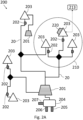
- Fig. 2A shows a block diagram of a power management system 200 for managing power distribution in an electrical power grid, according to some embodiments.
- the power management system 200 may allow management of power distribution, for instance manage power consumption and/or power production, in at least a portion of an electrical power grid 20.
- Management of power consumption and/or power production may include automatic enforcement of change to power consumption and/or power production in a power grid (e.g., allocate all power produced in the power grid to a dedicated power storage instead of using for power consumption).
- the power grid 20 may include a plurality of nodes where at least one power storage facility 201 may be coupled to at least one node managed by the power management system 200.
- At least one power storage facility 201 may be coupled to a consumer (e.g., a household) that consumes electrical power, and/or the at least one power storage facility 201 may be coupled to a power production facility (e.g., a renewable energy device, such as solar panels).
- a consumer e.g., a household
- a power production facility e.g., a renewable energy device, such as solar panels.
- the at least one power consumption rule 213 may include the user preferences for user defined life style or "comfort” (e.g., limiting minimal production facility charging rate, allowed flexibility of smart air conditioner temperature, etc.), and with increased flexibility on the "comfort" of the consumer (e.g., flexibility on ranges/thresholds of the at least one power consumption rule), the efficiency of the optimization of power consumption may be increased as well since there may be fewer restrictions on the optimization algorithm to reduce total costs.
- user preferences for user defined life style or "comfort” e.g., limiting minimal production facility charging rate, allowed flexibility of smart air conditioner temperature, etc.
- flexibility on ranges/thresholds of the at least one power consumption rule e.g., flexibility on ranges/thresholds of the at least one power consumption rule
- the computerized device 204 may apply the at least one power consumption rule 213 on power consumption data that have been analyzed by the computerized device 204, for instance applying the rule based on forecasted power consumption and/or forecasted power production and/or forecasted energy price and/or data received from the power consumption database 205 and/or the ambient condition database 206 and/or the renewable energy source database 207.
- the application of the at least one power consumption rule may be based on forecasted data.
- the power management system 200 automatically manages power consumption for the at least one consumer 203 within at least a portion of the power grid 20, based on the result of the application of the at least one power consumption rule 213, and also based on a power capacity status of the at least one power storage facility 201. Such management of power consumption produces optimization of power consumption that cannot be achieved by a human deciding on its own when and/or how to consume electrical power.
- the power management system 200 may send instructions to electrical appliances and/or the at least one power storage facility 201 to consume power from the power grid 20.
- the power grid 20 (e.g., defined geographically or physically based on nodes location in the power grid) may be regarded as a separate (e.g., self-sustaining) system, and the computerized device 204 analyzes influence of managing power consumption for the at least one consumer 203 on power distribution of the entire power grid 20 and update the at least one power consumption rule 213 to maintain power distribution of the power grid 20 below a first predefined threshold of total power consumption.
- the first predefined threshold may be based on power consumption data from consumers 203 that are geographically adjacent to the at least one consumer 203 (e.g., within the geographical area 210).
- the management system 200 manages power consumption in at least a portion of the power grid 20 for at least one consumer 203 coupled to the at least one power storage facility 201. In some embodiments, the management system 200 manages power consumption in at least a portion of the power grid 20 for at least one consumer 203 coupled to the at least one power storage facility 201 and also coupled to the at least one production facility 220.
- the management system 200 manages power consumption in at least a portion of the power grid 20 for at least one production facility 220 coupled to the at least one power storage facility 201, for instance a renewable energy power production facility that manages times when to store the power to the at least one power storage facility 201 and when to distribute the power to the power grid 20.
- the result of the application of the at least one power consumption rule is calculated based on a machine learning algorithm configured to increase power distribution of the power grid 20 towards a second predefined threshold.
- the machine learning algorithm may include a decision tree generated based on a consumer feedback loop.
- the computerized device 204 carries out at least one of: allocating power resources to the at least one power storage 201, retrieving power from the power grid 20, consuming power from the at least one power storage 201 instead of the power grid 20, and reallocating power resources to a different consumer 203 of the power grid 20.
- Fig. 2B shows a block diagram of a power management system 250 for managing power distribution without an electrical power grid, according to some embodiments.
- the power management system 250 manages power consumption for at least one consumer 203 coupled to the production facility 220 and also coupled to the at least one power storage facility 201. It should be noted that in case a consumer 203 wishes to manage power (e.g., in a closed community or a farm) without any connection to a power grid, the power management system 250 may automatically manage power for the consumer 203 based on the result of the application of at least one power consumption rule 213. Such management of power consumption produces optimization of power consumption that cannot be achieved by a human deciding on its own when and/or how to consume electrical power.
- the computerized device 204 carries out at least one of: allocating power resources from the at least one power production facility to the at least one power storage, and allocating power resources from the at least one power production facility to the power grid.
- the at least one power consumption rule 213 is applied 303 on the analyzed power consumption data, for instance based on forecasted power consumption and/or forecasted power production and/or forecasted energy price such that power consumption is automatically managed 304 for the at least one consumer 203, based on the result of the application of the at least one power consumption rule 213, and also based on a power capacity status (e.g., empty or 70% full) of the at least one power storage facility 201.
- a power capacity status e.g., empty or 70% full
- Such management of power consumption produces optimization of power consumption that cannot be achieved by a human deciding on its own when and/or how to consume electrical power.
- the power management system may automatically distribute power between the power grid and/or the power storage facility and/or individual electric appliances with the washing machine may be automatically operated at night by the power management system.
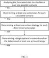
- the power management system may determine optimal management of power for the at least one consumer 203, taking as input at least one of forecasted power consumption and/or forecasted power production and/or forecasted energy costs. Multiple possible scenarios may be calculated based on the forecasted input and at least one (deterministic) action plan may be determined for each such scenario.
- the forecasted data may be analyzed 401 to calculate at least one possible scenario and determine 402 at least one action plan for each calculated scenario.
- At least one (conditional) action strategy may be determined 403 for each determined action plan, and a single optimal scenario may be determined 404 based on the determined at least one action strategy. For instance, a single optimal scenario may be determined using the at least one power consumption rule 213.
- determination of the optimal scenario is carried out using a hidden Markov model and/or using a Monte-Carlo evaluator.
- a power management system as described above may have an advantage for managing power over a plurality of consumers, compared to power consumption management for a single consumer (e.g., a single household).
- At least some of the reasons for the advantages may include: learning the relation between the user preferences (indicated in the at least one power consumption rule 213) and the corresponding effect on the power distribution within the power grid may be achieved faster when the learning is performed on multiple users, additionally a group of multiple users may share a common goal (e.g., reduce consumption from the power grid 20) and thereby automatically manage their power consumption based on that goal, with corresponding power consumption rules.
- a common goal e.g., reduce consumption from the power grid 20
- most households may have common hardware (electrical infrastructure, appliances, solar panels, etc.), these consumers may share similar constraints and thereby benefit from a system that manages power for a plurality of consumers.
- a group of users/consumers working for a "common goal" shares power therebetween, for instance if at least one user of the group has a production facility 220 then other users may buy/sell power produced within the group instead of consuming power from the power grid 20.
- the power management system maintains power consumption within a predefined range in order to prevent sharp changes, for instance with a predefined set of rules for each power grid. For example, in case that electrical power price forecast indicates low prices the power management system may prevent all users consuming at the same time, thereby possibly damaging the power grid and/or cause increase of the price due to the high consumption.
Landscapes
- Engineering & Computer Science (AREA)
- Power Engineering (AREA)
- Business, Economics & Management (AREA)
- Economics (AREA)
- Health & Medical Sciences (AREA)
- Human Resources & Organizations (AREA)
- Strategic Management (AREA)
- Theoretical Computer Science (AREA)
- Physics & Mathematics (AREA)
- General Physics & Mathematics (AREA)
- Marketing (AREA)
- General Business, Economics & Management (AREA)
- Tourism & Hospitality (AREA)
- Water Supply & Treatment (AREA)
- Primary Health Care (AREA)
- General Health & Medical Sciences (AREA)
- Public Health (AREA)
- Entrepreneurship & Innovation (AREA)
- Development Economics (AREA)
- Educational Administration (AREA)
- Game Theory and Decision Science (AREA)
- Operations Research (AREA)
- Quality & Reliability (AREA)
- Supply And Distribution Of Alternating Current (AREA)
- Management, Administration, Business Operations System, And Electronic Commerce (AREA)
Description
- The present invention generally relates to electric power systems. More particularly, the present invention relates to systems and methods for optimization of power consumption and/or optimization of power storage.
- In recent years, power consumption data has become available to providers (e.g. power plants) utilizing" smart" power consumption meters. These power consumption meters are usually directly coupled to a consumer, for instance coupled to a power grid of a private household, such that the power provider may at any time retrieve data from the meters, for instance retrieve power consumption data via a communication network.
- While a vast amount of power consumption data is available, there is still a need for a way to manage all of this data to determine power consumption data and/or power production data in electrical power grids.
- Problems of optimizing the power consumption in the grid with the help of available power consumption data have been recognized in the conventional art and various techniques have been developed to provide solutions, for example:
The publication "Multi-agent Autonomous Decision Making in Smart Micro-Grids' Energy Management: A Decentralized Approach", Ghorbani Sajad et al. (18TH International Conference, Austin, TX, USA, September 24-27, 2015) discloses a multi-agent based decentralized algorithm for a residential grid-connected micro-grid. As the fluctuating nature of renewable energy systems make the energy demand control very complex, one of the challenges in micro-grid energy control and management is to handle deviation from the prior forecasted power generation/consumption by optimizing the usage of storage and backup generation units in a way that preserves the users' convenience level. The publication is focused is on how to handle possible power imbalance situations with the help of an Autonomous Decentralized Multi-agent approach consisting of user agents, storage agent, and grid agent considering the users' consumption preferences as an important factor in the decision making.
Korean Patent Publication No.KR 2014/0075614 - The invention is set out by the appended claims.
- The subject matter regarded as the invention is set out by the appended claims. The invention, however, both as to organization and method of operation, together with objects, features, and advantages thereof, may best be understood by reference to the following detailed description when read with the accompanying drawings in which:
-
Fig. 1 shows a block diagram of an examplary computing device, according to some embodiments of the invention; -
Figs. 2A-2B show block diagrams of a power management system for managing power distribution in an electrical power grid, according to some embodiments of the invention; -
Fig. 3 which shows a flowchart of a method of managing power distribution in a portion of an electrical power grid, according to some embodiments of the invention; and -
Fig. 4 shows a which shows a flowchart of a method of determining optimal power consumption scenario, according to some embodiments of the invention. - It will be appreciated that for simplicity and clarity of illustration, elements shown in the figures have not necessarily been drawn to scale. For example, the dimensions of some of the elements may be exaggerated relative to other elements for clarity. Further, where considered appropriate, reference numerals may be repeated among the figures to indicate corresponding or analogous elements.
- In the following detailed description, numerous specific details are set forth in order to provide a thorough understanding of the invention. However, it will be understood by those skilled in the art that the present invention may be practiced without these specific details. In other instances, well-known methods, procedures, and components, modules, units and/or circuits have not been described in detail so as not to obscure the invention. Some features or elements described with respect to one embodiment may be combined with features or elements described with respect to other embodiments. For the sake of clarity, discussion of same or similar features or elements may not be repeated.
- Although embodiments of the invention are not limited in this regard, discussions utilizing terms such as, for example, "processing", "computing", "calculating", "determining", "establishing", "analyzing", "checking", or the like, may refer to operation(s) and/or process(es) of a computer, a computing platform, a computing system, or other electronic computing device, that manipulates and/or transforms data represented as physical (e.g., electronic) quantities within the computer's registers and/or memories into other data similarly represented as physical quantities within the computer's registers and/or memories or other information non-transitory storage medium that may store instructions to perform operations and/or processes. Although embodiments of the invention are not limited in this regard, the terms "plurality" and "a plurality" as used herein may include, for example, "multiple" or "two or more". The terms "plurality" or "a plurality" may be used throughout the specification to describe two or more components, devices, elements, units, parameters, or the like. The term set when used herein may include one or more items. Unless explicitly stated, the method embodiments described herein are not constrained to a particular order or sequence. Additionally, some of the described method embodiments or elements thereof can occur or be performed simultaneously, at the same point in time, or concurrently.
- Reference is made to
Fig. 1 , which is a schematic block diagram of an example of a computing device, according to some embodiments of the invention.Computing device 100 may include a controller or processor 105 (e.g., a central processing unit processor (CPU), a graphics processing unit (GPU), a chip or any suitable computing or computational device), anoperating system 115,memory 120,executable code 125,storage 130, input devices 135 (e.g. a keyboard or touchscreen), and output devices 140 (e.g., a display), a communication unit 145 (e.g., a cellular transmitter or modem, a Wi-Fi communication unit, or the like) for communicating with remote devices via a communication network, such as, for example, the Internet.Controller 105 may be configured to execute program code to perform operations described herein. The system described herein may include one or more computing device(s) 100. -
Operating system 115 may be or may include any code segment (e.g., one similar toexecutable code 125 described herein) designed and/or configured to perform tasks involving coordinating, scheduling, arbitrating, supervising, controlling or otherwise managing operation ofcomputing device 100, for example, scheduling execution of software programs or enabling software programs or other modules or units to communicate. -
Memory 120 may be or may include, for example, a Random Access Memory (RAM), a read only memory (ROM), a Dynamic RAM (DRAM), a Synchronous DRAM (SD-RAM), a double data rate (DDR) memory chip, a Flash memory, a volatile memory, a non-volatile memory, a cache memory, a buffer, a short term memory unit, a long term memory unit, or other suitable memory units or storage units.Memory 120 may be or may include a plurality of, possibly different memory units.Memory 120 may be a computer or processor non-transitory readable medium, or a computer non-transitory storage medium, e.g., a RAM. -
Executable code 125 may be any executable code, e.g., an application, a program, a process, task or script.Executable code 125 may be executed bycontroller 105 possibly under control ofoperating system 115. For example,executable code 125 may be a software application that performs methods as further described herein. Although, for the sake of clarity, a single item ofexecutable code 125 is shown inFig. 1 , a system according to embodiments of the invention may include a plurality of executable code segments similar toexecutable code 125 that may be stored intomemory 120 and causecontroller 105 to carry out methods described herein. -
Storage 130 may be or may include, for example, a hard disk drive, a universal serial bus (USB) device or other suitable removable and/or fixed storage unit. In some embodiments, some of the components shown inFig. 1 may be omitted. For example,memory 120 may be a non-volatile memory having the storage capacity ofstorage 130. Accordingly, although shown as a separate component,storage 130 may be embedded or included inmemory 120. -
Input devices 135 may be or may include a keyboard, a touch screen or pad, one or more sensors or any other or additional suitable input device. Any suitable number ofinput devices 135 may be operatively connected tocomputing device 100.Output devices 140 may include one or more displays or monitors and/or any other suitable output devices. Any suitable number ofoutput devices 140 may be operatively connected tocomputing device 100. Any applicable input/output (I/O) devices may be connected tocomputing device 100 as shown byblocks input devices 135 and/oroutput devices 140. - Embodiments of the invention may include an article such as a computer or processor non-transitory readable medium, or a computer or processor non-transitory storage medium, such as for example a memory, a disk drive, or a USB flash memory, encoding, including or storing instructions, e.g., computer-executable instructions, which, when executed by a processor or controller, carry out methods disclosed herein. For example, an article may include a storage medium such as
memory 120, computer-executable instructions such asexecutable code 125 and a controller such ascontroller 105. Such a non-transitory computer readable medium may be for example a memory, a disk drive, or a USB flash memory, encoding, including or storing instructions, e.g., computer-executable instructions, which when executed by a processor or controller, carry out methods disclosed herein. The storage medium may include, but is not limited to, any type of disk including, semiconductor devices such as read-only memories (ROMs) and/or random access memories (RAMs), flash memories, electrically erasable programmable read-only memories (EEPROMs) or any type of media suitable for storing electronic instructions, including programmable storage devices. For example, in some embodiments,memory 120 is a non-transitory machine-readable medium. - A system according to embodiments of the invention may include components such as, but not limited to, a plurality of central processing units (CPU), GPUs, or any other suitable multi-purpose or specific processors or controllers (e.g., controllers similar to controller 105), a plurality of input units, a plurality of output units, a plurality of memory units, and a plurality of storage units. A system may additionally include other suitable hardware components and/or software components. In some embodiments, a system may include or may be, for example, a personal computer, a desktop computer, a laptop computer, a workstation, a server computer, a network device, or any other suitable computing device.
- Reference is now made to
Fig. 2A , which shows a block diagram of apower management system 200 for managing power distribution in an electrical power grid, according to some embodiments. Thepower management system 200 may allow management of power distribution, for instance manage power consumption and/or power production, in at least a portion of anelectrical power grid 20. Management of power consumption and/or power production may include automatic enforcement of change to power consumption and/or power production in a power grid (e.g., allocate all power produced in the power grid to a dedicated power storage instead of using for power consumption). Thepower grid 20 may include a plurality of nodes where at least onepower storage facility 201 may be coupled to at least one node managed by thepower management system 200. For instance, at least onepower storage facility 201 may be coupled to a consumer (e.g., a household) that consumes electrical power, and/or the at least onepower storage facility 201 may be coupled to a power production facility (e.g., a renewable energy device, such as solar panels). - The
power management system 200 may include (e.g., smart)power consumption meters 202, to measure power consumption of at least oneconsumer 203 that is coupled thereto, so as to allow monitoring of the power consumption ofconsumers 203. In some embodiments, thepower consumption meters 202 are configured to allow communication with at least one analysis computerized device 204 (or central processor). In some embodiments, the computerized device (or processor) 204 is a computing device 100 (such as shown inFig. 1 ) with corresponding processing and memory elements configured to allow analyzing and processing of aggregated data from allconsumers 203. In some embodiments, thepower consumption meters 202 monitor power consumption of at least one electrical device of theconsumers 203. - It should be noted that communication with the
computerized device 204 may be carried out via a wireless network and/or via communication cables (for instance adjacent to electrical power grid 20). In some embodiments, differentpower consumption meters 202 communicate with thecomputerized device 204 via different networks, for instance a wired network and a cellular network. - According to some embodiments, the
power management system 200 includes a dedicatedpower consumption database 205, operably coupled to thecomputerized device 204, including data for the at least oneconsumer 203. In some embodiments, eachconsumer 203 has a user profile indicating typical power consumption of that user, for instance based on previous power consumption records from thepower consumption database 205. Thus, data received for that consumer 203 (e.g., from consumption meters 202) may be compared to the user profile in order to detect changes in power consumption. In some embodiments, thepower consumption database 205 maintains information regarding time-based events (e.g., annual events, holidays, weekends, etc.), also referred to herein as calendar data, for example, when people are on national holiday, for instance, they may use more electrical devices compared to weekdays where people are usually at work during the day. In some embodiments, calendar data is stored in a separate dedicated database. - According to some embodiments, the
computerized device 204 analyzes power consumption data from at least onepower consumption meter 202 connected to thepower grid 20, wherein the received power consumption data corresponds to consumption of the at least oneconsumer 203. In some embodiments, historical data may be analyzed as well. - In some embodiments, the
power management system 200 includes a dedicatedambient condition database 206 and a renewableenergy source database 207, operably coupled to thecomputerized device 204. For example, on a cold day, more heaters may be turned on, thereby increasing overall power consumption. Theambient condition database 206 may include information for weather conditions in a predefined geographical area 210 (indicated with a dashed line) corresponding to theelectrical power grid 20. In some embodiments, weather data fromambient condition database 206 includes values corresponding to prospective or future production of electrical power from a renewable energy source. For example, specific solar illumination intensity may correspond to a known power production level with solar panels (e.g., determined during calibration). In some embodiments, theambient condition database 206 includes information used for generation of a power production or power consumption forecast. It should be noted that, in an area having smart power consumption meters within a predetermined geographical zone, neighboring consumers may present similar power consumption behavior), such that these consumers may be grouped based on their power consumption, for instance grouped within a street, a portion of a street, a neighborhood or even within a city in order to consider the grouped consumers as a single cluster with substantially similar averaged power consumption for forecasting and managing power consumption in the grid. - According to some embodiments, the
power management system 200 includes at least one power production facility 220 (e.g., solar panels) coupled to thepower grid 20, such that saving power from theproduction facility 220 and by thepower storage facility 201 may be managed by thepower management system 200. For example, thecomputerized device 204 may analyze (e.g., using machine learning algorithms), for a particular time, the costs of consuming electrical power from thepower grid 20 compared to predicted costs at a later time (e.g., during the night when costs are lower) and send a command to a controlling device that would cause consumption (e.g., automatically operate a washing machine at household of consumer 203) to consume power from thepower grid 20 and/or consume power from thepower storage facility 201 and/or consume power generated from theproduction facility 220 at particular time periods such that the costs of consuming electrical power may be lower. - In some embodiments, a user of the
power grid 20, such as aconsumer 203 and/or an owner of aproduction facility 220 and/or a community of households trying to manage their power consumption within a predetermined range (e.g., a self-sustained community), creates at least onepower consumption rule 213 to be enforced on the power consumption. The at least onepower consumption rule 213 may include parameters (e.g., for time, costs, power usage, etc.), or ranges of parameters, that when these parameters occur the at least onepower consumption rule 213 may be enforced or applied to alter the power consumption. For example, enforcement of the at least onepower consumption rule 213 cause a particular result when a predefined condition occurs. If at least one parameter occurs in the system (e.g., if power consumption exceeds a predefined threshold), then a predefined change to the power consumption is enforced. The at least onepower consumption rule 213 may include preferences of the user of thepower grid 20 for power consumption behavior, for instance preferences for dates or time periods in which certain electrical appliances need to operate and/or maximal cost of power consumption from thepower grid 20 and/or minimal power to be stored by thepower storage facility 201 from the production facility 220 (e.g., as some users may desire to reduce their "ecological footprint"). If the at least onepower consumption rule 213 is enforced by thepower management system 200, the power consumption by the user of thepower grid 20 may be accordingly modified. For instance, if a first power consumption preference of the user of thepower grid 20 is applied the power consumption may be modified by a particular selected action. - For example, the at least one
power consumption rule 213 may include the user preferences for user defined life style or "comfort" (e.g., limiting minimal production facility charging rate, allowed flexibility of smart air conditioner temperature, etc.), and with increased flexibility on the "comfort" of the consumer (e.g., flexibility on ranges/thresholds of the at least one power consumption rule), the efficiency of the optimization of power consumption may be increased as well since there may be fewer restrictions on the optimization algorithm to reduce total costs. - According to some embodiments, the optimization algorithm may include a gradient search algorithm (or steepest descent algorithm). The gradient search algorithm may examine the status at each step all possible directions and chooses the direction with larger negative gradient, stopping at the local minimum (e.g., with minimum cost). For example, in the case of a nonlinear power production, paths may not be refined or analyzed since small change in the middle impacts the entire chain of events. In order to overcome computational complexity of the search algorithm, at least one of the following features may be introduced: "pruning of paths" to save only best N(t) paths for the next time; "post optimization refining" to partially evaluate pruned paths to check if they may lead to the better local minimum; and "price unification" to unify timestamps with similar electricity prices and thereby reduce substantially the number timestamps to optimize.
- In some embodiments, the optimization algorithm may be used with a generated set of predefined actions for the
system 200 with power production and/or power storage to minimize cost and/or maximize profit on the base of the consumption, production forecast and prices. For nonlinear power production, the gradient search driven algorithm may be used with pruning and/or refining. Thus, using the optimization algorithm, it may be possible to look up to for instance ten days ahead for optimal power storage operation windows in variable spot market environment. - The
computerized device 204 may apply the at least onepower consumption rule 213 on power consumption data that have been analyzed by thecomputerized device 204, for instance applying the rule based on forecasted power consumption and/or forecasted power production and/or forecasted energy price and/or data received from thepower consumption database 205 and/or theambient condition database 206 and/or the renewableenergy source database 207. In some embodiments, the application of the at least one power consumption rule may be based on forecasted data. For example, if the at least onepower consumption rule 213 states that for certain hours of the day the power consumption is to be carried out from thepower storage facility 201 instead of being carried out from thepower grid 20 in case that a threshold of power consumption costs is reached, then the rule may be applied on the analyzed power consumption data such that thepower management system 200 may generate a recommendation (or result of the application of the at least one rule) for how to manage the power consumption in accordance with the preferences of the user (based on the at least one power consumption rule 213). In some embodiments, the at least onepower consumption rule 213 includes preferences for power consumption based on the power capacity status of the at least onepower storage facility 201, for instance if the at least onepower storage facility 201 has less than forty percent capacity then the rule may indicate that power is to be consumed from thepower grid 20. - In some embodiments, the
power management system 200 automatically manages power consumption for the at least oneconsumer 203 within at least a portion of thepower grid 20, based on the result of the application of the at least onepower consumption rule 213, and also based on a power capacity status of the at least onepower storage facility 201. Such management of power consumption produces optimization of power consumption that cannot be achieved by a human deciding on its own when and/or how to consume electrical power. For example, thepower management system 200 may send instructions to electrical appliances and/or the at least onepower storage facility 201 to consume power from thepower grid 20. - In some embodiments, the power grid 20 (e.g., defined geographically or physically based on nodes location in the power grid) may be regarded as a separate (e.g., self-sustaining) system, and the
computerized device 204 analyzes influence of managing power consumption for the at least oneconsumer 203 on power distribution of theentire power grid 20 and update the at least onepower consumption rule 213 to maintain power distribution of thepower grid 20 below a first predefined threshold of total power consumption. The first predefined threshold may be based on power consumption data fromconsumers 203 that are geographically adjacent to the at least one consumer 203 (e.g., within the geographical area 210). - It should be noted that while multiple elements of the
power management system 200 shown inFig. 2A , some of these elements may be omitted according to the requirements of the user of the system. In some embodiments, themanagement system 200 manages power consumption in at least a portion of thepower grid 20 for at least oneconsumer 203 coupled to the at least onepower storage facility 201. In some embodiments, themanagement system 200 manages power consumption in at least a portion of thepower grid 20 for at least oneconsumer 203 coupled to the at least onepower storage facility 201 and also coupled to the at least oneproduction facility 220. - According to some embodiments, the
management system 200 manages power consumption in at least a portion of thepower grid 20 for at least oneproduction facility 220 coupled to the at least onepower storage facility 201, for instance a renewable energy power production facility that manages times when to store the power to the at least onepower storage facility 201 and when to distribute the power to thepower grid 20. - In some embodiments, the result of the application of the at least one power consumption rule is calculated based on a machine learning algorithm configured to increase power distribution of the
power grid 20 towards a second predefined threshold. The machine learning algorithm may include a decision tree generated based on a consumer feedback loop. - In some embodiments, the
computerized device 204 carries out at least one of: allocating power resources to the at least onepower storage 201, retrieving power from thepower grid 20, consuming power from the at least onepower storage 201 instead of thepower grid 20, and reallocating power resources to adifferent consumer 203 of thepower grid 20. - Reference is now made to
Fig. 2B , which shows a block diagram of apower management system 250 for managing power distribution without an electrical power grid, according to some embodiments. Thepower management system 250 manages power consumption for at least oneconsumer 203 coupled to theproduction facility 220 and also coupled to the at least onepower storage facility 201. It should be noted that in case aconsumer 203 wishes to manage power (e.g., in a closed community or a farm) without any connection to a power grid, thepower management system 250 may automatically manage power for theconsumer 203 based on the result of the application of at least onepower consumption rule 213. Such management of power consumption produces optimization of power consumption that cannot be achieved by a human deciding on its own when and/or how to consume electrical power. - In some embodiments, the
computerized device 204 carries out at least one of: allocating power resources from the at least one power production facility to the at least one power storage, and allocating power resources from the at least one power production facility to the power grid. - Reference is now made to
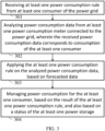
Fig. 3 , which shows a flowchart of a method of managing power distribution in a portion of anelectrical power grid 20, wherein thepower grid 20 includes at least onepower storage facility 201, according to some embodiments. At least onepower consumption rule 213 may be received 213 from at least oneconsumer 203 of thepower grid 20 such that power consumption data from at least onepower consumption meter 202 connected to thepower grid 20 may be analyzed 302 (e.g., by the computerized device 204), wherein the received power consumption data may correspond to consumption of the at least oneconsumer 203. In some embodiments, the at least onepower consumption rule 213 is applied 303 on the analyzed power consumption data, for instance based on forecasted power consumption and/or forecasted power production and/or forecasted energy price such that power consumption is automatically managed 304 for the at least oneconsumer 203, based on the result of the application of the at least onepower consumption rule 213, and also based on a power capacity status (e.g., empty or 70% full) of the at least onepower storage facility 201. Such management of power consumption produces optimization of power consumption that cannot be achieved by a human deciding on its own when and/or how to consume electrical power. For example, upon analysis of the received power consumption data, the power management system may automatically distribute power between the power grid and/or the power storage facility and/or individual electric appliances with the washing machine may be automatically operated at night by the power management system. - Reference is now made to
Fig. 4 , which shows a flowchart of a method of determining optimal power consumption scenario, according to some embodiments. The power management system may determine optimal management of power for the at least oneconsumer 203, taking as input at least one of forecasted power consumption and/or forecasted power production and/or forecasted energy costs. Multiple possible scenarios may be calculated based on the forecasted input and at least one (deterministic) action plan may be determined for each such scenario. The forecasted data may be analyzed 401 to calculate at least one possible scenario and determine 402 at least one action plan for each calculated scenario. At least one (conditional) action strategy may be determined 403 for each determined action plan, and a single optimal scenario may be determined 404 based on the determined at least one action strategy. For instance, a single optimal scenario may be determined using the at least onepower consumption rule 213. In some embodiments, determination of the optimal scenario is carried out using a hidden Markov model and/or using a Monte-Carlo evaluator. - It should be noted that a power management system as described above may have an advantage for managing power over a plurality of consumers, compared to power consumption management for a single consumer (e.g., a single household). At least some of the reasons for the advantages may include: learning the relation between the user preferences (indicated in the at least one power consumption rule 213) and the corresponding effect on the power distribution within the power grid may be achieved faster when the learning is performed on multiple users, additionally a group of multiple users may share a common goal (e.g., reduce consumption from the power grid 20) and thereby automatically manage their power consumption based on that goal, with corresponding power consumption rules. Since most households may have common hardware (electrical infrastructure, appliances, solar panels, etc.), these consumers may share similar constraints and thereby benefit from a system that manages power for a plurality of consumers.
- In some embodiments, a group of users/consumers working for a "common goal" shares power therebetween, for instance if at least one user of the group has a
production facility 220 then other users may buy/sell power produced within the group instead of consuming power from thepower grid 20. - In some embodiments, the power management system maintains power consumption within a predefined range in order to prevent sharp changes, for instance with a predefined set of rules for each power grid. For example, in case that electrical power price forecast indicates low prices the power management system may prevent all users consuming at the same time, thereby possibly damaging the power grid and/or cause increase of the price due to the high consumption.
- Various embodiments have been presented. Each of these embodiments may of course include features from other embodiments presented, and embodiments not specifically described may include various features described herein.
Claims (14)
- A method of managing power distribution in a portion of an electrical power grid, wherein the power grid (20) comprises at least one power storage (201), the method comprising:receiving at least one power consumption rule (213) from at least one consumer (203) of the power grid (20), wherein the at least one power consumption rule to be enforced to alter the power consumption when a predefined condition occurs;analyzing power consumption data from at least one power consumption meter (202) connected to the power grid (20), wherein the received power consumption data corresponds to consumption of the at least one consumer (203);receiving forecasted power consumption data selected from the group consisting of forecasted power consumption, forecasted power production, and forecasted energy prices;applying the at least one power consumption rule (213) on the analyzed power consumption data, wherein the applying the at least one power consumption rule is also based on forecasted power consumption data; andmanaging power consumption for the at least one consumer (203), based on the result of the applying the at least one power consumption rule (213), and also based on a power capacity status of the at least one power storage (201),analyzing influence of the managing power consumption for the at least one consumer (203) on power distribution of the power grid (20); andupdating the at least one power consumption rule (213) to maintain power distribution of the power grid (20) below a first predefined threshold of total power consumption.
- The method of claim 1, wherein the managing power consumption comprises one or more operations selected from the group consisting of: allocating power resources to the at least one power storage (201), retrieving power from the power grid (20), consuming power from the at least one power storage (201) instead of the power grid (20), and reallocating power resources to a different consumer of the power grid.
- The method of claims 1 or 2, wherein the managing power consumption comprises consuming power by an electrical appliance connected to the power grid (20).
- The method of any one of claims 1-3, wherein the power grid (20) further comprises at least one power production facility (220), and wherein the managing power consumption comprises at least one operation selected of: allocating power resources from the at least one power production facility (220) to the at least one power storage (201), and allocating power resources from the at least one power production facility (220) to the power grid (20).
- The method of claim 1, wherein the first predefined threshold is based on power consumption data from consumers that are geographically adjacent to the at least one consumer (203).
- The method of any one of claims 1-5, wherein the result of applying the at least one power consumption rule (213) is calculated based on a machine learning algorithm configured to increase power distribution of the power grid (20) towards a second predefined threshold.
- The method of claim 6, wherein the machine learning algorithm comprises a decision tree generated based on a consumer feedback loop.
- The method of any one of claims 1-7, further comprising:analyzing the forecasted data to calculate at least one possible scenario;determining at least one action plan for each calculated scenario;determining at least one action strategy for each determined action plan; anddetermining a single optimal scenario based on the determined at least one action strategy.
- The method of claim 8, wherein the at least one action plan is deterministic.
- The method of claim 8, wherein the at least one action strategy is conditional.
- The method of claim 8, wherein the single optimal scenario is determined based on the at least one power consumption rule.
- The method of claim 8, wherein the single optimal scenario is determined based on at least one of hidden Markov model and a Monte-Carlo evaluator.
- A system for managing power distribution in an electrical power grid (20), wherein the power grid (20) comprises at least one power storage (201), the system (200) comprising:at least one power consumption meter (202) connected to the power grid (20); anda processor (204), coupled to the at least one power consumption meter (202), and configured to implement the steps of a method according to any preceding claim.
- A non-transitory computer-readable medium comprising instructions that, when executed by a computing system comprising a memory (120) storing a plurality of program components executable by the computing system, cause the computing system to to carry out the steps of the method of any one of Claims 1-12.
Applications Claiming Priority (2)
| Application Number | Priority Date | Filing Date | Title |
|---|---|---|---|
| US201962851643P | 2019-05-23 | 2019-05-23 | |
| PCT/IL2020/050564 WO2020234887A1 (en) | 2019-05-23 | 2020-05-21 | System and method for optimization of power consumption and power storage |
Publications (4)
| Publication Number | Publication Date |
|---|---|
| EP3973494A1 EP3973494A1 (en) | 2022-03-30 |
| EP3973494A4 EP3973494A4 (en) | 2023-04-12 |
| EP3973494C0 EP3973494C0 (en) | 2025-07-02 |
| EP3973494B1 true EP3973494B1 (en) | 2025-07-02 |
Family
ID=73458447
Family Applications (1)
| Application Number | Title | Priority Date | Filing Date |
|---|---|---|---|
| EP20809731.1A Active EP3973494B1 (en) | 2019-05-23 | 2020-05-21 | System and method for optimization of power consumption and power storage |
Country Status (3)
| Country | Link |
|---|---|
| US (1) | US12046899B2 (en) |
| EP (1) | EP3973494B1 (en) |
| WO (1) | WO2020234887A1 (en) |
Families Citing this family (2)
| Publication number | Priority date | Publication date | Assignee | Title |
|---|---|---|---|---|
| WO2021129955A1 (en) * | 2019-12-27 | 2021-07-01 | Eaton Intelligent Power Limited | System and method for load and source forecasting for increasing electrical grid component longevity |
| IL308466B2 (en) | 2023-11-09 | 2025-05-01 | Foresight Energy Ltd | System and method of managing an electrical power grid with alternative power generation |
Family Cites Families (12)
| Publication number | Priority date | Publication date | Assignee | Title |
|---|---|---|---|---|
| US7274975B2 (en) | 2005-06-06 | 2007-09-25 | Gridpoint, Inc. | Optimized energy management system |
| WO2010083334A1 (en) * | 2009-01-14 | 2010-07-22 | Integral Analytics, Inc. | Optimization of microgrid energy use and distribution |
| US20110015797A1 (en) | 2009-07-14 | 2011-01-20 | Daniel Gilstrap | Method and apparatus for home automation and energy conservation |
| EP2460247A1 (en) | 2009-07-31 | 2012-06-06 | Gridmanager A/S | Method and apparatus for managing transmission of power in a power transmission network |
| US8676394B2 (en) | 2010-06-30 | 2014-03-18 | Siemens Aktiengesellschaft | Integrated demand response for energy utilization |
| US20120323382A1 (en) | 2011-06-15 | 2012-12-20 | Expanergy, Llc | Systems and methods to assess and optimize energy usage for a facility |
| US9563215B2 (en) * | 2012-07-14 | 2017-02-07 | Causam Energy, Inc. | Method and apparatus for actively managing electric power supply for an electric power grid |
| DE102012108065A1 (en) | 2012-08-30 | 2014-03-06 | EnBW Energie Baden-Württemberg AG | Energy consumer control method and control device based on an energy consumption profile |
| KR20140075614A (en) * | 2012-12-10 | 2014-06-19 | 주식회사 케이티 | Method for making smart energy consumption indicator |
| US10559044B2 (en) * | 2015-11-20 | 2020-02-11 | Opower, Inc. | Identification of peak days |
| US9645596B1 (en) * | 2016-11-23 | 2017-05-09 | Advanced Microgrid Solutions, Inc. | Method and apparatus for facilitating the operation of an on-site energy storage system to co-optimize battery dispatch |
| US20180225779A1 (en) * | 2017-02-07 | 2018-08-09 | Foresight Energy Ltd | System and method for determining power production in an electrical power grid |
-
2020
- 2020-05-21 EP EP20809731.1A patent/EP3973494B1/en active Active
- 2020-05-21 WO PCT/IL2020/050564 patent/WO2020234887A1/en not_active Ceased
- 2020-05-21 US US17/613,372 patent/US12046899B2/en active Active
Also Published As
| Publication number | Publication date |
|---|---|
| WO2020234887A1 (en) | 2020-11-26 |
| US12046899B2 (en) | 2024-07-23 |
| EP3973494A1 (en) | 2022-03-30 |
| EP3973494C0 (en) | 2025-07-02 |
| US20220209531A1 (en) | 2022-06-30 |
| EP3973494A4 (en) | 2023-04-12 |
Similar Documents
| Publication | Publication Date | Title |
|---|---|---|
| CN111492559B (en) | System and method for optimal control of an energy storage system | |
| JP7051856B2 (en) | Systems and methods for controlling dynamic energy storage systems | |
| Rokonuzzaman et al. | Levenberg-Marquardt algorithm-based solar PV energy integrated internet of home energy management system | |
| Jiang et al. | Dynamic residential demand response and distributed generation management in smart microgrid with hierarchical agents | |
| Dridi et al. | A novel deep reinforcement approach for IIoT microgrid energy management systems | |
| Nematirad et al. | Optimization of residential demand response program cost with consideration for occupants thermal comfort and privacy | |
| KR102343339B1 (en) | Method and apparatus for scheduling home appliance | |
| US10931107B2 (en) | System and method for management of an electricity distribution grid | |
| US20180225779A1 (en) | System and method for determining power production in an electrical power grid | |
| EP3973494B1 (en) | System and method for optimization of power consumption and power storage | |
| Razghandi et al. | Smart home energy management: sequence-to-sequence load forecasting and Q-learning | |
| US20140365023A1 (en) | Systems and Methods for Computer Implemented Energy Management | |
| Yassine et al. | Cooperative distributed multi-agent system for carbon-aware iiot in smart grids | |
| Ramos et al. | Selection of features in reinforcement learning applied to energy consumption forecast in buildings according to different contexts | |
| Raghavan et al. | Cost-optimal residential energy scheduling via a zero-shot LLM agent and model predictive control | |
| Al et al. | Smart home energy optimization system | |
| Al-Ani et al. | Optimal operation of water pumping stations | |
| Aguilar et al. | Analysis of data generated by an automated platform for aggregation of distributed energy resources | |
| Torriti | Flexibility | |
| Baliyan et al. | Predictive analytics for energy forecasting and optimization | |
| Solea et al. | A Comparative Study on Prosumers Load Demand and Production Forecasting Using Machine Learning and Time Series Techniques | |
| Tripathy et al. | Smart Green Cities Using IoT-Based Deep Reinforcement Learning Energy Management | |
| Kampars et al. | Predictive and optimisation models for AI driven electricity balancing platform | |
| Kyrtsilas et al. | Integrating industry 4.0 technologies for smart energy management in the industrial sector: trends and challenges | |
| Liu et al. | Fusing Decision Tree and Deep Reinforcement Learning for Demand Response Optimization of Variable Volume Water Heaters |
Legal Events
| Date | Code | Title | Description |
|---|---|---|---|
| STAA | Information on the status of an ep patent application or granted ep patent |
Free format text: STATUS: THE INTERNATIONAL PUBLICATION HAS BEEN MADE |
|
| PUAI | Public reference made under article 153(3) epc to a published international application that has entered the european phase |
Free format text: ORIGINAL CODE: 0009012 |
|
| STAA | Information on the status of an ep patent application or granted ep patent |
Free format text: STATUS: REQUEST FOR EXAMINATION WAS MADE |
|
| 17P | Request for examination filed |
Effective date: 20211202 |
|
| AK | Designated contracting states |
Kind code of ref document: A1 Designated state(s): AL AT BE BG CH CY CZ DE DK EE ES FI FR GB GR HR HU IE IS IT LI LT LU LV MC MK MT NL NO PL PT RO RS SE SI SK SM TR |
|
| DAV | Request for validation of the european patent (deleted) | ||
| DAX | Request for extension of the european patent (deleted) | ||
| A4 | Supplementary search report drawn up and despatched |
Effective date: 20230315 |
|
| RIC1 | Information provided on ipc code assigned before grant |
Ipc: H02J 3/38 20060101ALI20230309BHEP Ipc: H02J 3/28 20060101ALI20230309BHEP Ipc: H02J 3/14 20060101ALI20230309BHEP Ipc: H02J 3/00 20060101ALI20230309BHEP Ipc: G06Q 10/06 20120101ALI20230309BHEP Ipc: G05F 1/66 20060101ALI20230309BHEP Ipc: H02J 13/00 20060101ALI20230309BHEP Ipc: G06Q 50/06 20120101AFI20230309BHEP |
|
| GRAP | Despatch of communication of intention to grant a patent |
Free format text: ORIGINAL CODE: EPIDOSNIGR1 |
|
| STAA | Information on the status of an ep patent application or granted ep patent |
Free format text: STATUS: GRANT OF PATENT IS INTENDED |
|
| INTG | Intention to grant announced |
Effective date: 20250130 |
|
| GRAS | Grant fee paid |
Free format text: ORIGINAL CODE: EPIDOSNIGR3 |
|
| GRAA | (expected) grant |
Free format text: ORIGINAL CODE: 0009210 |
|
| STAA | Information on the status of an ep patent application or granted ep patent |
Free format text: STATUS: THE PATENT HAS BEEN GRANTED |
|
| RAP3 | Party data changed (applicant data changed or rights of an application transferred) |
Owner name: TIGO ENERGY AI LTD |
|
| AK | Designated contracting states |
Kind code of ref document: B1 Designated state(s): AL AT BE BG CH CY CZ DE DK EE ES FI FR GB GR HR HU IE IS IT LI LT LU LV MC MK MT NL NO PL PT RO RS SE SI SK SM TR |
|
| REG | Reference to a national code |
Ref country code: GB Ref legal event code: FG4D |
|
| REG | Reference to a national code |
Ref country code: CH Ref legal event code: EP |
|
| REG | Reference to a national code |
Ref country code: DE Ref legal event code: R096 Ref document number: 602020053908 Country of ref document: DE |
|
| REG | Reference to a national code |
Ref country code: IE Ref legal event code: FG4D |
|
| U01 | Request for unitary effect filed |
Effective date: 20250804 |
|
| U07 | Unitary effect registered |
Designated state(s): AT BE BG DE DK EE FI FR IT LT LU LV MT NL PT RO SE SI Effective date: 20250812 |
|
| PG25 | Lapsed in a contracting state [announced via postgrant information from national office to epo] |
Ref country code: IS Free format text: LAPSE BECAUSE OF FAILURE TO SUBMIT A TRANSLATION OF THE DESCRIPTION OR TO PAY THE FEE WITHIN THE PRESCRIBED TIME-LIMIT Effective date: 20251102 |
|
| PG25 | Lapsed in a contracting state [announced via postgrant information from national office to epo] |
Ref country code: NO Free format text: LAPSE BECAUSE OF FAILURE TO SUBMIT A TRANSLATION OF THE DESCRIPTION OR TO PAY THE FEE WITHIN THE PRESCRIBED TIME-LIMIT Effective date: 20251002 |
|
| PG25 | Lapsed in a contracting state [announced via postgrant information from national office to epo] |
Ref country code: HR Free format text: LAPSE BECAUSE OF FAILURE TO SUBMIT A TRANSLATION OF THE DESCRIPTION OR TO PAY THE FEE WITHIN THE PRESCRIBED TIME-LIMIT Effective date: 20250702 |
|
| PG25 | Lapsed in a contracting state [announced via postgrant information from national office to epo] |
Ref country code: GR Free format text: LAPSE BECAUSE OF FAILURE TO SUBMIT A TRANSLATION OF THE DESCRIPTION OR TO PAY THE FEE WITHIN THE PRESCRIBED TIME-LIMIT Effective date: 20251003 |
|
| PG25 | Lapsed in a contracting state [announced via postgrant information from national office to epo] |
Ref country code: CZ Free format text: LAPSE BECAUSE OF FAILURE TO SUBMIT A TRANSLATION OF THE DESCRIPTION OR TO PAY THE FEE WITHIN THE PRESCRIBED TIME-LIMIT Effective date: 20250702 |
|
| PG25 | Lapsed in a contracting state [announced via postgrant information from national office to epo] |
Ref country code: PL Free format text: LAPSE BECAUSE OF FAILURE TO SUBMIT A TRANSLATION OF THE DESCRIPTION OR TO PAY THE FEE WITHIN THE PRESCRIBED TIME-LIMIT Effective date: 20250702 |
|
| PG25 | Lapsed in a contracting state [announced via postgrant information from national office to epo] |
Ref country code: RS Free format text: LAPSE BECAUSE OF FAILURE TO SUBMIT A TRANSLATION OF THE DESCRIPTION OR TO PAY THE FEE WITHIN THE PRESCRIBED TIME-LIMIT Effective date: 20251002 |
|
| PG25 | Lapsed in a contracting state [announced via postgrant information from national office to epo] |
Ref country code: ES Free format text: LAPSE BECAUSE OF FAILURE TO SUBMIT A TRANSLATION OF THE DESCRIPTION OR TO PAY THE FEE WITHIN THE PRESCRIBED TIME-LIMIT Effective date: 20250702 |
|
| PG25 | Lapsed in a contracting state [announced via postgrant information from national office to epo] |
Ref country code: SM Free format text: LAPSE BECAUSE OF FAILURE TO SUBMIT A TRANSLATION OF THE DESCRIPTION OR TO PAY THE FEE WITHIN THE PRESCRIBED TIME-LIMIT Effective date: 20250702 |
|
| PG25 | Lapsed in a contracting state [announced via postgrant information from national office to epo] |
Ref country code: SK Free format text: LAPSE BECAUSE OF FAILURE TO SUBMIT A TRANSLATION OF THE DESCRIPTION OR TO PAY THE FEE WITHIN THE PRESCRIBED TIME-LIMIT Effective date: 20250702 |
|
| U1N | Appointed representative for the unitary patent procedure changed after the registration of the unitary effect |
Representative=s name: MARKS & CLERK LLP; GB |