EP3973348B1 - Kopfmontierte anzeigen - Google Patents
Kopfmontierte anzeigen Download PDFInfo
- Publication number
- EP3973348B1 EP3973348B1 EP19939604.5A EP19939604A EP3973348B1 EP 3973348 B1 EP3973348 B1 EP 3973348B1 EP 19939604 A EP19939604 A EP 19939604A EP 3973348 B1 EP3973348 B1 EP 3973348B1
- Authority
- EP
- European Patent Office
- Prior art keywords
- lens
- display
- module
- hmd device
- hmd
- Prior art date
- Legal status (The legal status is an assumption and is not a legal conclusion. Google has not performed a legal analysis and makes no representation as to the accuracy of the status listed.)
- Active
Links
Images


Classifications
-
- G—PHYSICS
- G02—OPTICS
- G02B—OPTICAL ELEMENTS, SYSTEMS OR APPARATUS
- G02B27/00—Optical systems or apparatus not provided for by any of the groups G02B1/00 - G02B26/00, G02B30/00
- G02B27/01—Head-up displays
- G02B27/017—Head mounted
- G02B27/0172—Head mounted characterised by optical features
-
- G—PHYSICS
- G02—OPTICS
- G02B—OPTICAL ELEMENTS, SYSTEMS OR APPARATUS
- G02B27/00—Optical systems or apparatus not provided for by any of the groups G02B1/00 - G02B26/00, G02B30/00
- G02B27/01—Head-up displays
- G02B27/0101—Head-up displays characterised by optical features
- G02B2027/011—Head-up displays characterised by optical features comprising device for correcting geometrical aberrations, distortion
-
- G—PHYSICS
- G02—OPTICS
- G02B—OPTICAL ELEMENTS, SYSTEMS OR APPARATUS
- G02B27/00—Optical systems or apparatus not provided for by any of the groups G02B1/00 - G02B26/00, G02B30/00
- G02B27/01—Head-up displays
- G02B27/0101—Head-up displays characterised by optical features
- G02B2027/014—Head-up displays characterised by optical features comprising information/image processing systems
Definitions
- Head-mounted display (HMD) devices are display systems worn on a user's head that include an electronic display and optics to enable the user to experience video and other multimedia data being streamed or otherwise transmitted to the display.
- HMD devices allow users to immerse themselves in a wide variety of extended reality (XR) environments that can include, for example, virtual and augmented reality (VR, AR) experiences ranging from entertainment to real-world applications.
- XR extended reality
- VR, AR virtual and augmented reality
- HMD technology continues to evolve as the number of different applications and use scenarios for HMD devices continue to increase.
- Documents US2018157043A1 and KR20160014507A disclose examples of HMD devices.
- Document WO2018126117A2 discloses an example of wearable imaging device to capture images or videos.
- Head-mounted display (HMD) technology continues to evolve as the number of different applications and use scenarios for HMD devices (also referred to as “headsets") continue to increase.
- the user experience can be optimized for a given HMD application or use scenario when the HMD device being used is produced with specific characteristics that are better suited for that application or scenario.
- HMD devices are manufactured with fixed eye cup designs that can accommodate a particular type of lens and display. While lens types can vary between different HMD device manufacturers, the types of lenses often used in HMD device designs are those with focal lengths that can provide good performance and a quality user experience over a range of applications.
- the eye cup geometry of an HMD device e.g., the size of the eye cup opening, and/or distances between the lens, the display, and the user's eye
- the type of lens i.e., the focal length
- each lens regardless of its type (i.e., focal length), comprises its own “lens profile” that defines optical characteristics such as chromatic aberrations and lens distortion (e.g., pincushion distortion).
- the optical characteristics can be associated with, and they can vary between, different manufacturers, makes, models, materials, and so on. Accordingly, for most HMD devices that come assembled with a fixed lens as noted above, an imaging system incorporates the lens profile of the fixed lens into an image calibration process that applies pre-distortions to images prior to rendering the images to the HMD display. The applied image pre-distortions are then neutralized as the images pass through the fixed lens so the images look correct to the user's eye.
- lenses can be replaced with corrective lenses that are designed for users who wear glasses.
- the corrective lens replacements create image artifacts such as the chromatic aberrations and distortion noted above, which can be corrected through a proper re-calibration.
- the imaging system is unaware that a lens has been replaced, and it is unable to apply the underlying lens profile associated with the replacement corrective lens. Therefore, re-calibration to correct for these image artifacts involves a tedious, manual re-calibration using the lens profile associated with the corrective lens.
- the manual re-calibration is often further complicated due to there being a different corrective lens for each of the user's eyes. Alleviating the artifacts therefore involves a distinct manual calibration for each lens.
- Optimizing experiences in these different use cases may call for using different lens types (e.g., different focal length lenses) and adjusting eye cup geometries, as well as re-calibrations of the HMD device according to specific lens profiles in order to provide images on the display that have appropriate corrective pre-distortions.
- users may also want to optimize certain display screen characteristics to enhance their experience with a given HMD application or use case. For example, in a particular application a user may want the display screen to provide brighter images, while in another application the user may want a higher contrast ratio from the display.
- optimizing the user experience with brighter images may involve using an HMD device assembled with an LCD display.
- optimizing the user experience with a higher contrast ratio may involve using an HMD device assembled with an OLED display.
- an example head-mounted display (HMD) device and methods described herein implement self-identifying, interchangeable lenses and displays to enable dynamic eye cup adjustment and device calibration.
- interchangeable lens and/or displays can provide self-identification through the HMD device to enable the device's imaging system to apply the correct calibration for the lens and/or displays.
- interchangeable lens and displays can be configured as interchangeable 'modules', where the modules can store and provide lens and display self-identification information.
- a module can comprise a structure such as a frame in which a lens and/or display is housed or integrated.
- a module can comprise a particular form factor that corresponds with the form factor of a module receiver or receptacle of an HMD device.
- Identification information stored on a module can include and/or enable the HMD device to access calibration profiles that are associated with an inserted lens and/or display so that an imaging system can correct for distortion, chromatic aberration, projection and lens centering, and other factors when displaying images on the display.
- the identification information also indicates a lens type (e.g., lens focal length) to enable a controller to make mechanical adjustments to the HMD eye cup shape based on the lens type.
- An example HMD device can include a variable lens and display receptacle that enables the insertion of lens and/or display modules containing different lenses and displays.
- a module can include stored identification information about an integrated lens or display, and the HMD device and/or receptacle can include a sensor to sense the identification information on the module, or the lens and display.
- a controller uses the identification information to determine a lens type and calibration profile, and controls mechanical adjustments to the HMD eye cup and makes distortion adjustments to images prior to displaying images on the HMD display.
- An actuator performs the mechanical adjustments based on geometric information from the controller, such as an applied distance between the lens at one end of the eye cup and a display panel at the opposite end of the eye cup.
- an HMD device includes a display, a variable lens receptacle to receive an interchangeable lens, a sensor to retrieve lens information from the lens, and a controller to obtain images that are pre-distorted according to the lens information, the controller to display the pre-distorted images on the display.
- the interchangeable lens can be housed in or integrated into a module having a form factor corresponding with the receptacle.
- the lens information comprises a lens calibration profile
- obtaining the pre-distorted images comprises the controller applying image pre-distortions based on the lens calibration profile prior to displaying the pre-distorted images on the display.
- a method of operating an HMD device includes receiving a lens module in the HMD device, retrieving lens information from the lens module, determining a lens type and a lens profile from the lens information, adjusting the shape of the HMD device eye cup based on the lens type, and calibrating the HMD device imaging system based on the lens profile.
- a head-mounted display (HMD) device includes a lens receptacle to receive a self-identifying, interchangeable lens module, a reading device to retrieve lens identification information stored on the lens module when the lens module is inserted into the lens receptacle, and a controller to calibrate the HMD device based on the lens identification information.
- HMD head-mounted display
- FIG. 1A shows a perspective view and block diagram view of an example head-mounted display (HMD) device 100 suitable for implementing self-identifying, interchangeable lenses and displays to enable dynamic eye cup adjustment and device calibration.
- the example HMD device 100 includes a strap 102 or other attachment mechanism such as a helmet that enables a user to mount the device 100 on the user's head.
- the HMD device 100 also includes an eye cup 104 and lens and display receptacles 106, 108, positioned near opposite ends of the eye cup 104.
- the receptacles can comprise, for example, a frame structure with a particular form factor that enables the insertion of HMD device components having a corresponding form factor.
- Such components can include interchangeable lenses 110 and electronic displays 112, or corresponding modules containing interchangeable lenses and/or electronic displays for insertion into a receptacle 106 or 108. While lenses 110 and displays 112 are discussed and shown in the figures as being housed, packaged, or otherwise integrated within modules, other examples are possible, such as having the lenses and displays themselves manufactured with appropriate form factors for insertion into the HMD device receptacles 106 and 108.
- an example HMD device 100 can also include a controller 118 and a mechanical actuator 120.
- An example controller 118 can include a processor (CPU) 122, memory 124, and other electronics (not shown) for communicating with and controlling components of the HMD device 100.
- a memory 124 can include both volatile and nonvolatile memory components comprising non-transitory, machine-readable (e.g., computer/processor-readable) media that can provide for the storage of machine-readable coded program instructions, data structures, program instruction modules, and other data and/or instructions executable by a processor 122 of the HMD device 100.
- Such instructions, data structures, and modules can include, for example, a lens profile 130, a display profile 132, an eye cup adjustment instruction module 134, and an image pre-distortion instruction module 136, which are discussed in more detail herein below.
- the example HMD device 100 illustrated in FIG. 1A is configured as an "all-in-one" device. That is, the HMD device 100 shown in FIG. 1A not only operates as an image displaying device, but it also operates as an image processing device that processes images before they are displayed, for example, in accordance with a lens profile 130 and instructions from image pre-distortion module 136. In some examples of an "all-in-one" HMD device 100, images can be generated remotely and processed with pre-distortion on the HMD device 100. In other examples of an "all-in-one" HMD device 100, images can be both generated and processed with pre-distortion on the HMD device 100.
- an HMD device 100 may not be configured as an "all-in-one" device, but instead may be configured so that some or all of the image processing can be performed on a remote device prior to images being displayed on the HMD device 100.
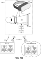
- FIG. 1B shows an example HMD device 100 that illustrates a number of different configurations in which image processing and other processing (eye cup adjustments implementing instructions from module 134) can occur on a device that is remote from the HMD device 100.
- an HMD device 100 can be coupled to a remote PC 121 or other processing device through a tethered or wired connection 123, such as through an HDMI cable.
- a tethered or wired connection 123 such as through an HDMI cable.
- an HMD device 100 can be coupled to a remote PC 121 or other processing device through a wireless connection 125.
- a wireless connection 125 can include any suitable wireless communication protocol such as Bluetooth TM , ZigBee TM , Z-Wave TM , and the like.
- an HMD device 100 can be coupled to a remote computing device such as a server 127 in a cloud network 129.
- Cloud network 129 can represent any of a variety of network topologies and types (including optical, wired and/or wireless networks), employing any of a variety of network protocols (including public and/or proprietary protocols).
- a cloud network 129 may include, for example, a home network, a corporate network, and the Internet, as well as one or multiple local area networks (LANs) and/or wide area networks (WANs) and combinations thereof.
- processing components including lens profile 130, display profile 132, eye cup adjustment instruction module 134, and image pre-distortion instruction module 136 can be implemented on remote computing devices to provide image processing for an example HMD device 100 in the same or similar manner as described herein with respect to the "all-in-one" HMD device shown in FIG. 1A .
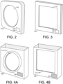
- FIG. 2 shows an example of an interchangeable lens 110 integrated into a lens module 114.
- FIG. 3 shows an example of an electronic display 112 integrated into a display module 116.
- the modules 114 and 116 comprise a form factor that facilitates their insertion and extraction with different lenses 110 and displays 112 into HMD device receptacles 106 and 108.
- FIGs. 4A and 4B show examples of HMD device receptacles 106 and 108, respectively.
- FIG. 4A shows an example of a lens receptacle 106 with a lens 110 and lens module 114 inserted into the receptacle 106
- FIG. 4B shows an example of a display receptacle 108 with a display 112 and display module 116 inserted into the receptacle 108.
- an interchangeable lens 110 can include any of a variety of different types of lenses that have associated lens calibration profiles. Therefore, an interchangeable lens 110 can include a lens with a different focal length and/or different optical center, a prescription lens to address problems such as astigmatism, myopia or hyperopia, a lens made from different materials including glass, plastic, and other materials, a Fresnel lens, a lens stack, and so on.
- appropriate interchangeable lenses provided by different manufacturers can have varying levels of optical quality based on levels of refined materials, chemicals, and processes used to manufacture the lenses.
- a lens calibration profile 130 associated with such interchangeable lenses 110 enables the HMD device controller 118 (discussed below) to provide appropriate pre-distortions to images.
- An interchangeable display 112 can include different types of display panels such as OLED display panels or LCD display panels. Displays can have different display screen characteristics such as the display resolution, the refresh rate, the contrast ratio, and the brightness level. Similar to the lens profile 130 discussed above, an interchangeable display 112 can include an associated display profile 132 that enables the HMD device controller 118 to provide appropriate image calibrations to help optimize images based on the display characteristics.
- a lens module 114 can store lens information 126 that is readable by a reader 128 or sensor 128 on the HMD device 100 or on the lens receptacle 106 in the device 100.
- a display module 116 can store display information 141 that is readable by a reader/sensor 129.
- Lens and display information 126, 141 can be stored on modules 114, 116 using various types of storage devices 131, 133, including, for example, an RFID tag or microchip, a QR code, an IR code, or an onboard memory accessible by electrical connections.
- Such electrical connections can include, for example, multiple electrical connectors to make contact with corresponding connections on a PC board or set of conductors on the lens module 114.
- connections can be pre-wired, pre-routed, or otherwise configured to provide short or open electrical connections that can identify the lens without the involvement of active electronics or a power source.
- the readers 128 and 129 can comprise an RFID reader, a QR code reader, an IR reader, or the controller 118 that reads a memory 131, 133 onboard the modules 114, 116 when the modules are inserted into the receptacles 106, 108.
- Lens information 126 can include lens identification information that identifies the lens type (e.g., lens focal length), as well as the manufacturer, model, materials, manufacturing processes, and so on.
- the controller 118 can access the lens information 126 from storage 131 through the reader 128.
- the controller 118 can access the lens focal length and other lens characteristics.
- Controller 118 can execute instructions from an eye cup adjustment instruction module 134 stored in memory 124 in order to determine an amount of mechanical adjustment to apply to the eye cup 104 to optimize the field of view for the inserted lens.
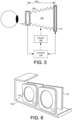
- FIG. 5 shows an example eye cup 104 formed from a flexible material 138 (e.g., accordion style material) to accommodate such mechanical adjustments that can expand and contract the size of the eye cup 104, varying the distance 140 between the lens 110 and display 112.
- Controller 118 can control mechanical actuator 120 to adjust the geometry of the eye cup 104.
- other geometries of the eye cup 104 can also be adjusted, such as the size of the eye cup opening.
- the controller 118 or other local or remote processing device can also match the lens information 126 with a lens profile 130, and can use the lens profile 130 in an image pre-distortion calibration process (e.g., executing instructions from image pre-distortion instruction module 136) to apply appropriate pre-distortions to images prior to their being displayed on the display.
- a lens profile 130 can be stored in an onboard memory 131 of the lens module 114 and can be accessed by the controller 118 or remote processing device through the reader 128.
- Display information 141 can include display identification information that identifies the display type (e.g., OLED, LCD), as well as the manufacturer, model, display resolution, screen refresh rate, contrast ratio, brightness levels, and other characteristics.
- the controller 118 can access the display information 141 from storage 133 through the reader 143.
- the controller 118 can determine a display profile 132 that can be used in an image pre-distortion calibration process (e.g., executing instructions from image pre-distortion instruction module 136) to apply appropriate pre-distortions to images prior to their being displayed on the display.
- a display profile 132 can be stored in an onboard memory 133 of the display module 116 and can be accessed by the controller 118 through the reader 143.
- FIG. 6 shows an example of a dual lens and display module 142 that accommodates two lenses and two display panels.
- the lens and displays can be in fixed relative positions.
- such a dual module 142 can comprise expandable and contractible components that enable the distance between the lenses and displays to be varied in a manner similar to that discussed above with regard to FIG. 3 .
- FIGs. 7 and 8 are flow diagrams showing example methods 700 and 800 of operating a head-mounted display (HMD) device.
- Method 800 comprises extensions of method 700 and incorporates additional details of method 700.
- Methods 700 and 800 are associated with examples discussed above with regard to FIGs. 1A , 1B - 6 , and details of the operations shown in methods 700 and 800 can be found in the related discussion of such examples.
- the operations of methods 700 and 800 may be embodied as programming instructions stored on a non-transitory, machine-readable (e.g., computer/processor-readable) medium, such as memory/storage 124 shown in FIG. 1A .
- implementing the operations of methods 700 and 800 can be achieved by a controller with a processor, such as a controller 118 with a processor 122 of FIG. 1A , reading and executing programming instructions stored in a memory 124. In some examples, implementing the operations of methods 700 and 800 can be achieved using an ASIC and/or other hardware components alone or in combination with programming instructions executable by a processor 122.
- the methods 700 and 800 may include more than one implementation, and different implementations of methods 700 and 800 may not employ every operation presented in the respective flow diagrams of FIGs. 7 and 8 . Therefore, while the operations of methods 700 and 800 are presented in a particular order within their respective flow diagrams, the order of their presentations is not intended to be a limitation as to the order in which the operations may actually be implemented, or as to whether all of the operations may be implemented. For example, one implementation of method 800 might be achieved through the performance of a number of initial operations, without performing other subsequent operations, while another implementation of method 800 might be achieved through the performance of all of the operations.
- an example method 700 of operating a head-mounted display (HMD) device begins at block 702 with receiving a lens module in the HMD device, where the lens module comprises an interchangeable lens.
- the method continues with retrieving lens information from the lens module (block 704), and determining a lens type and a lens profile from the lens information (block 706).
- the method further includes adjusting an eye cup shape of the HMD device based on the lens type (block 708), and calibrating images with pre-distortion based on the lens profile (block 710).
- method 800 comprises extensions of method 700 and incorporates additional details of method 700. Accordingly, method 800 begins at block 802 with receiving a lens module in the HMD device, where the lens module comprises an interchangeable lens. The method can continue with retrieving lens information from the lens module (block 804), determining a lens type and a lens profile from the lens information (block 806), adjusting an eye cup shape of the HMD device based on the lens type (block 808), and calibrating images with pre-distortion based on the lens profile (block 810).
- adjusting an eye cup shape can include changing a distance between the lens module and a display panel of the head-mounted display, and/or changing the size of the eye cup opening (block 812).
- calibrating images with pre-distortion can include applying barrel distortion and chromatic distortion to the images (block 814).
- retrieving lens information from the lens module can include reading the lens information from a storage device on the lens module (block 816).
- determining a lens profile can include reading the lens profile from a memory on the lens module (block 818).
- the method can also include receiving a display module in the HMD device, where the display module includes an interchangeable display (block 820).
- the method can also include retrieving display information from the display module (block 822), and calibrating images with pre-distortion based on the display information (block 824).
Landscapes
- Physics & Mathematics (AREA)
- General Physics & Mathematics (AREA)
- Optics & Photonics (AREA)
Claims (14)
- Kopfmontierte Anzeige(Head-Mounted Display - HMD)-Vorrichtung (100), die umfasst:eine Anzeige (112);eine variable Linsenaufnahme (106), um eine austauschbare Linse (110) aufzunehmen;einen Sensor (128), um Linseninformationen von der Linse zu erlangen;eine Steuerung (118), um Bilder zu erhalten, die gemäß den Linseninformationen vorverzerrt sind, wobei die Steuerung die vorverzerrten Bilder auf der Anzeige anzeigt;dadurch gekennzeichnet, dass es ferner umfasst:eine Augenmuschel (104), die ein flexibles Material (138) umfasst, um eine Anpassung an die Augenmuschelform zu ermöglichen, wobei die Augenmuschel ein erstes und ein zweites entgegengesetztes Ende umfasst, wobei die Linsenaufnahme an dem ersten Ende positioniert ist und die Anzeige an dem zweiten Ende positioniert ist;ein Bedienungselement (120), um die Form der Augenmuschel zu variieren;wobei die Steuerung dazu dient, einen Linsentyp von den Linseninformationen zu bestimmen und das Bedienungselement zu steuern, um die Form der Augenmuschel auf der Basis von dem Linsentyp anzupassen.
- HMD-Vorrichtung nach Anspruch 1, wobei:die Linseninformationen (126) ein Linsenkalibrierungsprofil (130) umfassen; unddas Erhalten der vorverzerrten Bilder umfasst, dass die Steuerung (118) Bildvorverzerrungen auf der Basis von dem Linsenkalibrierungsprofil anwendet, bevor die vorverzerrten Bilder auf der Anzeige angezeigt werden.
- HMD-Vorrichtung nach Anspruch 1, wobei der Sensor (128) ausgewählt ist aus einem RFID-Leser, einem QR-Code-Leser, einem IR-Transceiver und einer elektrischen Verbindung zu einem Speicher (131) an Bord der Linse.
- HMD-Vorrichtung nach Anspruch 1, wobei die Anzeige eine austauschbare Anzeige umfasst, wobei die HMD-Vorrichtung ferner umfasst:eine variable Anzeigenaufnahme (108), um austauschbare Anzeigen (112) aufzunehmen;einen Sensor (129) auf der variable Anzeigenaufnahme, um Anzeigeinformationen von einer austauschbaren Anzeige, die in die variable Anzeigenaufnahme eingesetzt ist, zu erlangen; undwobei die Steuerung (118) dazu dient, ein Anzeigeprofil (132) von den Anzeigeinformationen zu bestimmen und Vorverzerrungen auf die Bilder auf der Basis von dem Anzeigeprofil anzuwenden, bevor die Bilder an die austauschbare Anzeige gesendet werden.
- Kopfmontierte Anzeige(HMD)-Vorrichtung nach Anspruch 1, wobei:die variable Linsenaufnahme (106) dazu dient, ein selbstidentifizierendes, austauschbares Linsenmodul (114) aufzunehmen;der Sensor (128) Teil einer Lesevorrichtung ist, um Linsenidentifikationsinformationen, die auf dem Linsenmodul (114) gespeichert sind, zu erlangen, wenn das Linsenmodul in die Linsenaufnahme eingesetzt ist; unddie Steuerung dazu dient, die HMD-Vorrichtung auf der Basis von den Linsenidentifikationsinformationen zu kalibrieren.
- HMD-Vorrichtung nach Anspruch 5, wobei das Bedienungselement ein mechanisches Bedienungselement (120) ist, das durch die Steuerung (118) gesteuert wird, um die Form der Augenmuschel (104) auf der Basis von den Linsenidentifikationsinformationen anzupassen.
- HMD-Vorrichtung nach Anspruch 5, wobei die Linsenidentifikationsinformationen ein Linsenkalibrierungsprofil (130) umfassen und dass die Steuerung (118) die HMD-Vorrichtung (100) kalibriert, das Vorverzerren von Bildern auf der Basis des Linsenkalibrierungsprofils vor dem Senden der Bilder an die Anzeige umfasst.
- HMD-Vorrichtung nach Anspruch 5, wobeidie Anzeigeaufnahme dazu dient, ein selbstidentifizierendes, austauschbares Anzeigemodul (116) aufzunehmen;wobei die HMD-Vorrichtung (100) ferner eine zweite Lesevorrichtung (129) auf der Anzeigeaufnahme umfasst, um Anzeigeidentifikationsinformationen, die auf dem Anzeigemodul gespeichert sind, abzurufen, wenn das Anzeigemodul in die Anzeigeaufnahme eingesetzt ist; undwobei die Steuerung ferner dazu dient, die HMD-Vorrichtung auf der Basis von den Anzeigeidentifikationsinformationen zu kalibrieren.
- Verfahren zum Bedienen einer kopfmontierten Anzeige(HMD)-Vorrichtung (100), das umfasst:Empfangen (702, 802) eines Linsenmoduls (114) in der HMD-Vorrichtung, wobei das Objektivmodul eine austauschbare Linse (110) umfasst;Erlangen (704, 804) von Linseninformationen von dem Linsenmodul;Bestimmen (706, 806) eines Linsentyps und eines Linsenprofils von den Linseninformationen;dadurch gekennzeichnet, dass es ferner umfasst:Anpassen (708, 808) einer Augenmuschelform der HMD-Vorrichtung auf der Basis von dem Linsentyp; undKalibrieren (710, 810) von Bildern mit Vorverzerrung auf der Basis von dem Linsenprofil.
- Verfahren nach Anspruch 9, wobei das Anpassen einer Augenmuschelform ein Ändern (812) eines Abstands (140) zwischen dem Linsenmodul und einem Anzeigefeld der kopfmontierten Anzeige umfasst.
- Verfahren nach Anspruch 9, wobei das Kalibrieren von Bildern mit Vorverzerrung das Anwenden (814) einer Tonnenverzerrung und einer chromatischen Verzerrung auf die Bilder umfasst.
- Verfahren nach Anspruch 9, wobei das Erlangen von Linseninformationen von dem Linsenmodul das Lesen (816) der Linseninformationen von einer Speichervorrichtung auf dem Linsenmodul umfasst.
- Verfahren nach Anspruch 9, wobei das Bestimmen eines Linsenprofils das Lesen (818) des Linsenprofils von einem Speicher auf dem Linsenmodul umfasst.
- Verfahren nach Anspruch 9, das ferner umfasst:Empfangen (820) eines Anzeigemoduls in der HMD-Vorrichtung, wobei das Anzeigemodul eine austauschbare Anzeige umfasst;Erlangen (822) von Anzeigeinformationen von dem Anzeigemodul; undKalibrieren (824) von Bildern mit Vorverzerrung auf der Basis von den Anzeigeinformationen.
Applications Claiming Priority (1)
| Application Number | Priority Date | Filing Date | Title |
|---|---|---|---|
| PCT/US2019/044325 WO2021021155A1 (en) | 2019-07-31 | 2019-07-31 | Head-mounted displays |
Publications (3)
| Publication Number | Publication Date |
|---|---|
| EP3973348A1 EP3973348A1 (de) | 2022-03-30 |
| EP3973348A4 EP3973348A4 (de) | 2023-02-15 |
| EP3973348B1 true EP3973348B1 (de) | 2025-04-02 |
Family
ID=74230466
Family Applications (1)
| Application Number | Title | Priority Date | Filing Date |
|---|---|---|---|
| EP19939604.5A Active EP3973348B1 (de) | 2019-07-31 | 2019-07-31 | Kopfmontierte anzeigen |
Country Status (4)
| Country | Link |
|---|---|
| US (1) | US12025803B2 (de) |
| EP (1) | EP3973348B1 (de) |
| CN (1) | CN114270243B (de) |
| WO (1) | WO2021021155A1 (de) |
Families Citing this family (5)
| Publication number | Priority date | Publication date | Assignee | Title |
|---|---|---|---|---|
| JP7562700B2 (ja) * | 2020-05-20 | 2024-10-07 | マジック リープ, インコーポレイテッド | コヒーレントコンテキストを用いた、ピース毎の漸次的かつ持続的な較正 |
| JP7788470B2 (ja) * | 2021-05-18 | 2025-12-18 | グーグル エルエルシー | 統合された処方レンズを含むウェアラブルヘッドアップディスプレイを較正して整列および色補正された画像を生成するための方法ならびにシステム |
| US12585114B2 (en) | 2021-05-18 | 2026-03-24 | Google Llc | Method and system for calibrating a wearable heads-up display including integrated prescription lenses to produce aligned and color corrected images |
| US20240280818A1 (en) * | 2021-06-16 | 2024-08-22 | Apple Inc. | Head-mountable devices with connectable lens assemblies |
| US20240369843A1 (en) * | 2021-09-22 | 2024-11-07 | Apple Inc. | A head mountable device comprising adjustable and modular lenses |
Citations (1)
| Publication number | Priority date | Publication date | Assignee | Title |
|---|---|---|---|---|
| US20190369402A1 (en) * | 2016-12-30 | 2019-12-05 | Gopro, Inc. | Wearable imaging device |
Family Cites Families (26)
| Publication number | Priority date | Publication date | Assignee | Title |
|---|---|---|---|---|
| US5642221A (en) | 1994-03-09 | 1997-06-24 | Optics 1, Inc. | Head mounted display system |
| US7501996B2 (en) | 2004-06-03 | 2009-03-10 | United States Of America As Represented By The Secretary Of The Navy | Immersive input display apparatus |
| US8028350B2 (en) | 2007-12-31 | 2011-10-04 | Pan-Optx, Inc. | Adjustable eyecup eyewear and methods of use |
| US8957835B2 (en) * | 2008-09-30 | 2015-02-17 | Apple Inc. | Head-mounted display apparatus for retaining a portable electronic device with display |
| FR2943797B1 (fr) | 2009-03-27 | 2011-03-18 | Thales Sa | Systeme d'imagerie a afficheur actif et muni d'une bonnette |
| AU2011227042B2 (en) | 2010-03-19 | 2014-03-06 | Oakley, Inc. | Goggle |
| US9116337B1 (en) | 2012-03-21 | 2015-08-25 | Google Inc. | Increasing effective eyebox size of an HMD |
| EP3058418B1 (de) | 2013-10-16 | 2023-10-04 | Magic Leap, Inc. | Kopfhörer für virtuelle oder erweiterte realität mit einstellbarem zwischenpupillenabstand |
| KR102298200B1 (ko) * | 2013-11-21 | 2021-09-07 | 삼성전자 주식회사 | 헤드 마운트 디스플레이 장치 |
| WO2015126987A1 (en) | 2014-02-18 | 2015-08-27 | Merge Labs, Inc. | Head mounted display goggles for use with mobile computing devices |
| US10228562B2 (en) * | 2014-02-21 | 2019-03-12 | Sony Interactive Entertainment Inc. | Realtime lens aberration correction from eye tracking |
| US20150253574A1 (en) | 2014-03-10 | 2015-09-10 | Ion Virtual Technology Corporation | Modular and Convertible Virtual Reality Headset System |
| US9551873B2 (en) | 2014-05-30 | 2017-01-24 | Sony Interactive Entertainment America Llc | Head mounted device (HMD) system having interface with mobile computing device for rendering virtual reality content |
| KR102321362B1 (ko) | 2014-07-29 | 2021-11-04 | 삼성전자주식회사 | 헤드 마운트 디스플레이 디바이스가 영상을 디스플레이하는 방법 및 그 헤드 마운트 디스플레이 디바이스 |
| US10261579B2 (en) | 2014-09-01 | 2019-04-16 | Samsung Electronics Co., Ltd. | Head-mounted display apparatus |
| KR102230076B1 (ko) | 2014-09-01 | 2021-03-19 | 삼성전자 주식회사 | 헤드 마운트 디스플레이 장치 |
| US9472025B2 (en) | 2015-01-21 | 2016-10-18 | Oculus Vr, Llc | Compressible eyecup assemblies in a virtual reality headset |
| KR101726676B1 (ko) * | 2015-05-20 | 2017-04-14 | 엘지전자 주식회사 | 헤드 마운티드 디스플레이 |
| US9880441B1 (en) * | 2016-09-08 | 2018-01-30 | Osterhout Group, Inc. | Electrochromic systems for head-worn computer systems |
| EP3343268A4 (de) | 2016-03-31 | 2018-10-10 | Shenzhen Royole Technologies Co., Ltd. | Gasschirm und wearable-vorrichtung |
| JP6551285B2 (ja) | 2016-04-12 | 2019-07-31 | ブラザー工業株式会社 | アイカップ付ヘッドマウントディスプレイ |
| US10156723B2 (en) | 2016-05-12 | 2018-12-18 | Google Llc | Display pre-distortion methods and apparatus for head-mounted displays |
| WO2018044584A1 (en) * | 2016-08-31 | 2018-03-08 | Nextvr Inc. | Methods and apparatus related to capturing and/or rendering images |
| US10444512B2 (en) | 2017-02-27 | 2019-10-15 | Facebook Technologies, Llc | Optical characterization system for lenses |
| US10261324B2 (en) | 2017-08-10 | 2019-04-16 | Facebook Technologies, Llc | Removable lens assembly for a head-mounted display |
| US10663738B2 (en) | 2017-12-04 | 2020-05-26 | Samsung Electronics Co., Ltd. | System and method for HMD configurable for various mobile device sizes |
-
2019
- 2019-07-31 CN CN201980099076.5A patent/CN114270243B/zh active Active
- 2019-07-31 US US17/414,338 patent/US12025803B2/en active Active
- 2019-07-31 EP EP19939604.5A patent/EP3973348B1/de active Active
- 2019-07-31 WO PCT/US2019/044325 patent/WO2021021155A1/en not_active Ceased
Patent Citations (1)
| Publication number | Priority date | Publication date | Assignee | Title |
|---|---|---|---|---|
| US20190369402A1 (en) * | 2016-12-30 | 2019-12-05 | Gopro, Inc. | Wearable imaging device |
Also Published As
| Publication number | Publication date |
|---|---|
| CN114270243B (zh) | 2024-08-09 |
| US20220350144A1 (en) | 2022-11-03 |
| EP3973348A1 (de) | 2022-03-30 |
| WO2021021155A1 (en) | 2021-02-04 |
| CN114270243A (zh) | 2022-04-01 |
| EP3973348A4 (de) | 2023-02-15 |
| US12025803B2 (en) | 2024-07-02 |
Similar Documents
| Publication | Publication Date | Title |
|---|---|---|
| EP3973348B1 (de) | Kopfmontierte anzeigen | |
| US9710215B2 (en) | Maximizing native capability across multiple monitors | |
| CN110322818B (zh) | 显示装置及操作方法 | |
| CN108700740B (zh) | 用于头戴式显示器的显示预失真方法和装置 | |
| CN114063302B (zh) | 光学像差校正的方法和装置 | |
| CN100399326C (zh) | 在信息终端显示图像用的信息处理系统 | |
| US10712563B2 (en) | Methods for near-to-eye displays exploiting optical focus and depth information extraction | |
| KR20200130359A (ko) | 주변 이미지 영역에서의 실시간 압축을 통한 이미지 디스플레이의 제어 | |
| US10338410B1 (en) | Eyeglass prescription correction for optics blocks in head-mounted displays | |
| US20210255462A1 (en) | Method, Computer Program Product and Binocular Headset Controller | |
| WO2013148702A1 (en) | Techniques for user profiles for viewing devices | |
| WO2018046892A1 (en) | Adjusting display data | |
| US20180225878A1 (en) | Apparatus and method for augmented reality presentation | |
| WO2019217260A1 (en) | Dynamic foveated display | |
| US20130127821A1 (en) | Method and system for adjusting a display to account for the users' corrective lenses or preferred display settings | |
| US20250299367A1 (en) | Online calibration with convolutional neural network or other machine learning model for video see-through extended reality | |
| US20240346779A1 (en) | Dynamic alignment between see-through cameras and eye viewpoints in video see-through (vst) extended reality (xr) | |
| US20230127083A1 (en) | Optical link system for head mounted display and method of controlling the same | |
| US12458466B2 (en) | Flexible and tensioned camera apparatus with electronic module system for enabling maneuverable stereoscopic field of view | |
| US20150243248A1 (en) | Image processing apparatus, display apparatus, and image processing system and method, for displaying image data | |
| US20240288892A1 (en) | Technique to reduce voltage regulator output noise in phase modulated high speed interface | |
| US20220414828A1 (en) | Electronic apparatus, control method thereof and electronic system | |
| CN106933359A (zh) | 一种vr一体机及其图像调整方法 | |
| US12272278B2 (en) | Head-mounted display and method for image processing based on diopter adjustment | |
| US12620072B2 (en) | Distortion combination and correction for final views in video see-through (VST) augmented reality (AR) |
Legal Events
| Date | Code | Title | Description |
|---|---|---|---|
| STAA | Information on the status of an ep patent application or granted ep patent |
Free format text: STATUS: THE INTERNATIONAL PUBLICATION HAS BEEN MADE |
|
| PUAI | Public reference made under article 153(3) epc to a published international application that has entered the european phase |
Free format text: ORIGINAL CODE: 0009012 |
|
| STAA | Information on the status of an ep patent application or granted ep patent |
Free format text: STATUS: REQUEST FOR EXAMINATION WAS MADE |
|
| 17P | Request for examination filed |
Effective date: 20211223 |
|
| AK | Designated contracting states |
Kind code of ref document: A1 Designated state(s): AL AT BE BG CH CY CZ DE DK EE ES FI FR GB GR HR HU IE IS IT LI LT LU LV MC MK MT NL NO PL PT RO RS SE SI SK SM TR |
|
| DAV | Request for validation of the european patent (deleted) | ||
| DAX | Request for extension of the european patent (deleted) | ||
| A4 | Supplementary search report drawn up and despatched |
Effective date: 20230118 |
|
| RIC1 | Information provided on ipc code assigned before grant |
Ipc: G02B 27/01 19950101AFI20230112BHEP |
|
| GRAP | Despatch of communication of intention to grant a patent |
Free format text: ORIGINAL CODE: EPIDOSNIGR1 |
|
| STAA | Information on the status of an ep patent application or granted ep patent |
Free format text: STATUS: GRANT OF PATENT IS INTENDED |
|
| INTG | Intention to grant announced |
Effective date: 20250103 |
|
| GRAS | Grant fee paid |
Free format text: ORIGINAL CODE: EPIDOSNIGR3 |
|
| GRAA | (expected) grant |
Free format text: ORIGINAL CODE: 0009210 |
|
| STAA | Information on the status of an ep patent application or granted ep patent |
Free format text: STATUS: THE PATENT HAS BEEN GRANTED |
|
| AK | Designated contracting states |
Kind code of ref document: B1 Designated state(s): AL AT BE BG CH CY CZ DE DK EE ES FI FR GB GR HR HU IE IS IT LI LT LU LV MC MK MT NL NO PL PT RO RS SE SI SK SM TR |
|
| REG | Reference to a national code |
Ref country code: GB Ref legal event code: FG4D |
|
| REG | Reference to a national code |
Ref country code: CH Ref legal event code: EP |
|
| REG | Reference to a national code |
Ref country code: IE Ref legal event code: FG4D |
|
| REG | Reference to a national code |
Ref country code: DE Ref legal event code: R096 Ref document number: 602019068288 Country of ref document: DE |
|
| REG | Reference to a national code |
Ref country code: NL Ref legal event code: MP Effective date: 20250402 |
|
| PG25 | Lapsed in a contracting state [announced via postgrant information from national office to epo] |
Ref country code: NL Free format text: LAPSE BECAUSE OF FAILURE TO SUBMIT A TRANSLATION OF THE DESCRIPTION OR TO PAY THE FEE WITHIN THE PRESCRIBED TIME-LIMIT Effective date: 20250402 |
|
| REG | Reference to a national code |
Ref country code: AT Ref legal event code: MK05 Ref document number: 1781826 Country of ref document: AT Kind code of ref document: T Effective date: 20250402 |
|
| PG25 | Lapsed in a contracting state [announced via postgrant information from national office to epo] |
Ref country code: FI Free format text: LAPSE BECAUSE OF FAILURE TO SUBMIT A TRANSLATION OF THE DESCRIPTION OR TO PAY THE FEE WITHIN THE PRESCRIBED TIME-LIMIT Effective date: 20250402 Ref country code: PT Free format text: LAPSE BECAUSE OF FAILURE TO SUBMIT A TRANSLATION OF THE DESCRIPTION OR TO PAY THE FEE WITHIN THE PRESCRIBED TIME-LIMIT Effective date: 20250804 Ref country code: ES Free format text: LAPSE BECAUSE OF FAILURE TO SUBMIT A TRANSLATION OF THE DESCRIPTION OR TO PAY THE FEE WITHIN THE PRESCRIBED TIME-LIMIT Effective date: 20250402 |
|
| PGFP | Annual fee paid to national office [announced via postgrant information from national office to epo] |
Ref country code: DE Payment date: 20250620 Year of fee payment: 7 |
|
| REG | Reference to a national code |
Ref country code: LT Ref legal event code: MG9D |
|
| PG25 | Lapsed in a contracting state [announced via postgrant information from national office to epo] |
Ref country code: GR Free format text: LAPSE BECAUSE OF FAILURE TO SUBMIT A TRANSLATION OF THE DESCRIPTION OR TO PAY THE FEE WITHIN THE PRESCRIBED TIME-LIMIT Effective date: 20250703 Ref country code: NO Free format text: LAPSE BECAUSE OF FAILURE TO SUBMIT A TRANSLATION OF THE DESCRIPTION OR TO PAY THE FEE WITHIN THE PRESCRIBED TIME-LIMIT Effective date: 20250702 |
|
| PG25 | Lapsed in a contracting state [announced via postgrant information from national office to epo] |
Ref country code: PL Free format text: LAPSE BECAUSE OF FAILURE TO SUBMIT A TRANSLATION OF THE DESCRIPTION OR TO PAY THE FEE WITHIN THE PRESCRIBED TIME-LIMIT Effective date: 20250402 |
|
| PG25 | Lapsed in a contracting state [announced via postgrant information from national office to epo] |
Ref country code: BG Free format text: LAPSE BECAUSE OF FAILURE TO SUBMIT A TRANSLATION OF THE DESCRIPTION OR TO PAY THE FEE WITHIN THE PRESCRIBED TIME-LIMIT Effective date: 20250402 |
|
| PG25 | Lapsed in a contracting state [announced via postgrant information from national office to epo] |
Ref country code: HR Free format text: LAPSE BECAUSE OF FAILURE TO SUBMIT A TRANSLATION OF THE DESCRIPTION OR TO PAY THE FEE WITHIN THE PRESCRIBED TIME-LIMIT Effective date: 20250402 |
|
| PG25 | Lapsed in a contracting state [announced via postgrant information from national office to epo] |
Ref country code: AT Free format text: LAPSE BECAUSE OF FAILURE TO SUBMIT A TRANSLATION OF THE DESCRIPTION OR TO PAY THE FEE WITHIN THE PRESCRIBED TIME-LIMIT Effective date: 20250402 |
|
| PG25 | Lapsed in a contracting state [announced via postgrant information from national office to epo] |
Ref country code: RS Free format text: LAPSE BECAUSE OF FAILURE TO SUBMIT A TRANSLATION OF THE DESCRIPTION OR TO PAY THE FEE WITHIN THE PRESCRIBED TIME-LIMIT Effective date: 20250702 |
|
| PG25 | Lapsed in a contracting state [announced via postgrant information from national office to epo] |
Ref country code: IS Free format text: LAPSE BECAUSE OF FAILURE TO SUBMIT A TRANSLATION OF THE DESCRIPTION OR TO PAY THE FEE WITHIN THE PRESCRIBED TIME-LIMIT Effective date: 20250802 |
|
| PG25 | Lapsed in a contracting state [announced via postgrant information from national office to epo] |
Ref country code: LV Free format text: LAPSE BECAUSE OF FAILURE TO SUBMIT A TRANSLATION OF THE DESCRIPTION OR TO PAY THE FEE WITHIN THE PRESCRIBED TIME-LIMIT Effective date: 20250402 |
|
| REG | Reference to a national code |
Ref country code: DE Ref legal event code: R097 Ref document number: 602019068288 Country of ref document: DE |
|
| PG25 | Lapsed in a contracting state [announced via postgrant information from national office to epo] |
Ref country code: DK Free format text: LAPSE BECAUSE OF FAILURE TO SUBMIT A TRANSLATION OF THE DESCRIPTION OR TO PAY THE FEE WITHIN THE PRESCRIBED TIME-LIMIT Effective date: 20250402 Ref country code: SM Free format text: LAPSE BECAUSE OF FAILURE TO SUBMIT A TRANSLATION OF THE DESCRIPTION OR TO PAY THE FEE WITHIN THE PRESCRIBED TIME-LIMIT Effective date: 20250402 |
|
| PG25 | Lapsed in a contracting state [announced via postgrant information from national office to epo] |
Ref country code: CZ Free format text: LAPSE BECAUSE OF FAILURE TO SUBMIT A TRANSLATION OF THE DESCRIPTION OR TO PAY THE FEE WITHIN THE PRESCRIBED TIME-LIMIT Effective date: 20250402 |
|
| PG25 | Lapsed in a contracting state [announced via postgrant information from national office to epo] |
Ref country code: EE Free format text: LAPSE BECAUSE OF FAILURE TO SUBMIT A TRANSLATION OF THE DESCRIPTION OR TO PAY THE FEE WITHIN THE PRESCRIBED TIME-LIMIT Effective date: 20250402 |
|
| PG25 | Lapsed in a contracting state [announced via postgrant information from national office to epo] |
Ref country code: RO Free format text: LAPSE BECAUSE OF FAILURE TO SUBMIT A TRANSLATION OF THE DESCRIPTION OR TO PAY THE FEE WITHIN THE PRESCRIBED TIME-LIMIT Effective date: 20250402 Ref country code: SK Free format text: LAPSE BECAUSE OF FAILURE TO SUBMIT A TRANSLATION OF THE DESCRIPTION OR TO PAY THE FEE WITHIN THE PRESCRIBED TIME-LIMIT Effective date: 20250402 |
|
| PG25 | Lapsed in a contracting state [announced via postgrant information from national office to epo] |
Ref country code: IT Free format text: LAPSE BECAUSE OF FAILURE TO SUBMIT A TRANSLATION OF THE DESCRIPTION OR TO PAY THE FEE WITHIN THE PRESCRIBED TIME-LIMIT Effective date: 20250402 |
|
| PLBE | No opposition filed within time limit |
Free format text: ORIGINAL CODE: 0009261 |
|
| STAA | Information on the status of an ep patent application or granted ep patent |
Free format text: STATUS: NO OPPOSITION FILED WITHIN TIME LIMIT |
|
| REG | Reference to a national code |
Ref country code: CH Ref legal event code: L10 Free format text: ST27 STATUS EVENT CODE: U-0-0-L10-L00 (AS PROVIDED BY THE NATIONAL OFFICE) Effective date: 20260211 |
|
| REG | Reference to a national code |
Ref country code: CH Ref legal event code: H13 Free format text: ST27 STATUS EVENT CODE: U-0-0-H10-H13 (AS PROVIDED BY THE NATIONAL OFFICE) Effective date: 20260224 |
|
| 26N | No opposition filed |
Effective date: 20260105 |
|
| PG25 | Lapsed in a contracting state [announced via postgrant information from national office to epo] |
Ref country code: LU Free format text: LAPSE BECAUSE OF NON-PAYMENT OF DUE FEES Effective date: 20250731 |
|
| GBPC | Gb: european patent ceased through non-payment of renewal fee |
Effective date: 20250731 |
|
| REG | Reference to a national code |
Ref country code: BE Ref legal event code: MM Effective date: 20250731 |
|
| PG25 | Lapsed in a contracting state [announced via postgrant information from national office to epo] |
Ref country code: GB Free format text: LAPSE BECAUSE OF NON-PAYMENT OF DUE FEES Effective date: 20250731 |
|
| PG25 | Lapsed in a contracting state [announced via postgrant information from national office to epo] |
Ref country code: BE Free format text: LAPSE BECAUSE OF NON-PAYMENT OF DUE FEES Effective date: 20250731 |
|
| PG25 | Lapsed in a contracting state [announced via postgrant information from national office to epo] |
Ref country code: FR Free format text: LAPSE BECAUSE OF NON-PAYMENT OF DUE FEES Effective date: 20250731 |
|
| PG25 | Lapsed in a contracting state [announced via postgrant information from national office to epo] |
Ref country code: CH Free format text: LAPSE BECAUSE OF NON-PAYMENT OF DUE FEES Effective date: 20250731 |