EP3973068B1 - Improvements in and relating to effluent - Google Patents
Improvements in and relating to effluent Download PDFInfo
- Publication number
- EP3973068B1 EP3973068B1 EP20873360.0A EP20873360A EP3973068B1 EP 3973068 B1 EP3973068 B1 EP 3973068B1 EP 20873360 A EP20873360 A EP 20873360A EP 3973068 B1 EP3973068 B1 EP 3973068B1
- Authority
- EP
- European Patent Office
- Prior art keywords
- effluent
- sulphate
- pfs
- methane
- fde
- Prior art date
- Legal status (The legal status is an assumption and is not a legal conclusion. Google has not performed a legal analysis and makes no representation as to the accuracy of the status listed.)
- Active
Links
Images





Classifications
-
- C—CHEMISTRY; METALLURGY
- C02—TREATMENT OF WATER, WASTE WATER, SEWAGE, OR SLUDGE
- C02F—TREATMENT OF WATER, WASTE WATER, SEWAGE, OR SLUDGE
- C02F3/00—Biological treatment of water, waste water, or sewage
- C02F3/28—Anaerobic digestion processes
-
- C—CHEMISTRY; METALLURGY
- C02—TREATMENT OF WATER, WASTE WATER, SEWAGE, OR SLUDGE
- C02F—TREATMENT OF WATER, WASTE WATER, SEWAGE, OR SLUDGE
- C02F1/00—Treatment of water, waste water, or sewage
- C02F1/52—Treatment of water, waste water, or sewage by flocculation or precipitation of suspended impurities
- C02F1/5236—Treatment of water, waste water, or sewage by flocculation or precipitation of suspended impurities using inorganic agents
- C02F1/5245—Treatment of water, waste water, or sewage by flocculation or precipitation of suspended impurities using inorganic agents using basic salts, e.g. of aluminium and iron
-
- C—CHEMISTRY; METALLURGY
- C02—TREATMENT OF WATER, WASTE WATER, SEWAGE, OR SLUDGE
- C02F—TREATMENT OF WATER, WASTE WATER, SEWAGE, OR SLUDGE
- C02F11/00—Treatment of sludge; Devices therefor
-
- C—CHEMISTRY; METALLURGY
- C02—TREATMENT OF WATER, WASTE WATER, SEWAGE, OR SLUDGE
- C02F—TREATMENT OF WATER, WASTE WATER, SEWAGE, OR SLUDGE
- C02F1/00—Treatment of water, waste water, or sewage
- C02F1/52—Treatment of water, waste water, or sewage by flocculation or precipitation of suspended impurities
- C02F1/5281—Installations for water purification using chemical agents
-
- C—CHEMISTRY; METALLURGY
- C02—TREATMENT OF WATER, WASTE WATER, SEWAGE, OR SLUDGE
- C02F—TREATMENT OF WATER, WASTE WATER, SEWAGE, OR SLUDGE
- C02F2101/00—Nature of the contaminant
- C02F2101/10—Inorganic compounds
- C02F2101/101—Sulfur compounds
-
- C—CHEMISTRY; METALLURGY
- C02—TREATMENT OF WATER, WASTE WATER, SEWAGE, OR SLUDGE
- C02F—TREATMENT OF WATER, WASTE WATER, SEWAGE, OR SLUDGE
- C02F2101/00—Nature of the contaminant
- C02F2101/30—Organic compounds
- C02F2101/32—Hydrocarbons, e.g. oil
- C02F2101/322—Volatile compounds, e.g. benzene
-
- C—CHEMISTRY; METALLURGY
- C02—TREATMENT OF WATER, WASTE WATER, SEWAGE, OR SLUDGE
- C02F—TREATMENT OF WATER, WASTE WATER, SEWAGE, OR SLUDGE
- C02F2103/00—Nature of the water, waste water, sewage or sludge to be treated
- C02F2103/007—Contaminated open waterways, rivers, lakes or ponds
-
- C—CHEMISTRY; METALLURGY
- C02—TREATMENT OF WATER, WASTE WATER, SEWAGE, OR SLUDGE
- C02F—TREATMENT OF WATER, WASTE WATER, SEWAGE, OR SLUDGE
- C02F2103/00—Nature of the water, waste water, sewage or sludge to be treated
- C02F2103/20—Nature of the water, waste water, sewage or sludge to be treated from animal husbandry
-
- C—CHEMISTRY; METALLURGY
- C02—TREATMENT OF WATER, WASTE WATER, SEWAGE, OR SLUDGE
- C02F—TREATMENT OF WATER, WASTE WATER, SEWAGE, OR SLUDGE
- C02F2103/00—Nature of the water, waste water, sewage or sludge to be treated
- C02F2103/22—Nature of the water, waste water, sewage or sludge to be treated from the processing of animals, e.g. poultry, fish, or parts thereof
-
- C—CHEMISTRY; METALLURGY
- C02—TREATMENT OF WATER, WASTE WATER, SEWAGE, OR SLUDGE
- C02F—TREATMENT OF WATER, WASTE WATER, SEWAGE, OR SLUDGE
- C02F2209/00—Controlling or monitoring parameters in water treatment
- C02F2209/005—Processes using a programmable logic controller [PLC]
-
- C—CHEMISTRY; METALLURGY
- C02—TREATMENT OF WATER, WASTE WATER, SEWAGE, OR SLUDGE
- C02F—TREATMENT OF WATER, WASTE WATER, SEWAGE, OR SLUDGE
- C02F2209/00—Controlling or monitoring parameters in water treatment
- C02F2209/11—Turbidity
-
- C—CHEMISTRY; METALLURGY
- C02—TREATMENT OF WATER, WASTE WATER, SEWAGE, OR SLUDGE
- C02F—TREATMENT OF WATER, WASTE WATER, SEWAGE, OR SLUDGE
- C02F2303/00—Specific treatment goals
- C02F2303/02—Odour removal or prevention of malodour
-
- C—CHEMISTRY; METALLURGY
- C02—TREATMENT OF WATER, WASTE WATER, SEWAGE, OR SLUDGE
- C02F—TREATMENT OF WATER, WASTE WATER, SEWAGE, OR SLUDGE
- C02F2305/00—Use of specific compounds during water treatment
- C02F2305/02—Specific form of oxidant
-
- C—CHEMISTRY; METALLURGY
- C02—TREATMENT OF WATER, WASTE WATER, SEWAGE, OR SLUDGE
- C02F—TREATMENT OF WATER, WASTE WATER, SEWAGE, OR SLUDGE
- C02F2307/00—Location of water treatment or water treatment device
- C02F2307/08—Treatment of wastewater in the sewer, e.g. to reduce grease, odour
-
- C—CHEMISTRY; METALLURGY
- C12—BIOCHEMISTRY; BEER; SPIRITS; WINE; VINEGAR; MICROBIOLOGY; ENZYMOLOGY; MUTATION OR GENETIC ENGINEERING
- C12P—FERMENTATION OR ENZYME-USING PROCESSES TO SYNTHESISE A DESIRED CHEMICAL COMPOUND OR COMPOSITION OR TO SEPARATE OPTICAL ISOMERS FROM A RACEMIC MIXTURE
- C12P5/00—Preparation of hydrocarbons or halogenated hydrocarbons
- C12P5/02—Preparation of hydrocarbons or halogenated hydrocarbons acyclic
- C12P5/023—Methane
-
- Y—GENERAL TAGGING OF NEW TECHNOLOGICAL DEVELOPMENTS; GENERAL TAGGING OF CROSS-SECTIONAL TECHNOLOGIES SPANNING OVER SEVERAL SECTIONS OF THE IPC; TECHNICAL SUBJECTS COVERED BY FORMER USPC CROSS-REFERENCE ART COLLECTIONS [XRACs] AND DIGESTS
- Y02—TECHNOLOGIES OR APPLICATIONS FOR MITIGATION OR ADAPTATION AGAINST CLIMATE CHANGE
- Y02E—REDUCTION OF GREENHOUSE GAS [GHG] EMISSIONS, RELATED TO ENERGY GENERATION, TRANSMISSION OR DISTRIBUTION
- Y02E50/00—Technologies for the production of fuel of non-fossil origin
- Y02E50/30—Fuel from waste, e.g. synthetic alcohol or diesel
-
- Y—GENERAL TAGGING OF NEW TECHNOLOGICAL DEVELOPMENTS; GENERAL TAGGING OF CROSS-SECTIONAL TECHNOLOGIES SPANNING OVER SEVERAL SECTIONS OF THE IPC; TECHNICAL SUBJECTS COVERED BY FORMER USPC CROSS-REFERENCE ART COLLECTIONS [XRACs] AND DIGESTS
- Y02—TECHNOLOGIES OR APPLICATIONS FOR MITIGATION OR ADAPTATION AGAINST CLIMATE CHANGE
- Y02P—CLIMATE CHANGE MITIGATION TECHNOLOGIES IN THE PRODUCTION OR PROCESSING OF GOODS
- Y02P60/00—Technologies relating to agriculture, livestock or agroalimentary industries
- Y02P60/20—Reduction of greenhouse gas [GHG] emissions in agriculture, e.g. CO2
- Y02P60/22—Methane [CH4], e.g. from rice paddies
Definitions
- the present invention relates to improvements in and relating to effluent.
- improvements in, and relating to, methane reduction in relation to animal effluent are particularly advantageous.
- the present invention will now primarily for ease of reference be described in relation to a dairy farm effluent treatment system. However, it is envisaged the present invention may well have application to other sources of animal effluent so any such discussion should not necessarily be seen as limiting.
- the vast majority (> 92%) of the greenhouse gas emissions from the Manure Management category are in the form of methane gas produced during storage and management of farm dairy effluent. When effluent is stored in ponds, the organic matter in the effluent decomposes anaerobically producing methane gas.
- methane emissions from the manure management contributed 1,475.1 kt CO 2 -e; which represents 92.4% of the Manure Management category (MFE, 2019a).
- the remainder 121.6 kt CO 2 -e (7.2 %) is nitrous oxide produced by nitrification and denitrification processes (i.e. ⁇ 8% of the manure management category).
- Manure Management contributed 4.1% of greenhouse gas emissions from the total New Zealand agricultural sector making it the third largest GHG category after Enteric Fermentation and Agricultural Soils categories.
- Manure Management accounts for about 10% of the methane emissions from dairy farms (MPI, 2012; Laubach et al., 2015).
- the New Zealand Ministry for the Environment Interactive GHG Inventory states that in 2017 the amount of methane emitted from dairy cattle manure ponds was equivalent to 1,255 kt CO 2 -e and that dairy cattle enteric fermentation emissions of methane was equivalent to 13,560 kt CO 2 -e. Thus, the total amount of methane emitted from New Zealand dairy farms was equivalent to 14,815 kt CO 2 -e and 8.5% of this total amount came from manure management (i.e. ponds).
- an animal effluent treatment system could be devised which could reduce the risk of methane emissions from animal effluent and especially from animal effluent storage ponds or the like.
- this review teaches away from using a treatment solution, such as polyferric sulphate or ferric sulphate, because it only lists the following options to reduce methane emissions: (i) covering the effluent pond and flaring of CH 4 , with or without energy recovery; (ii) bio-filter cover, comprising CH 4 consuming bacteria, on the pond surface; (iii) effluent acidification; (iv) conversion of anaerobic to aerobic or facultative ponds; (v) solids separation to physically prevent solids from entering anaerobic ponds and depositing them in aerobic conditions on pastures instead; and (vi) reduce the time of effluent storage in anaerobic ponds (MPI, 2014).
- a treatment solution such as polyferric sulphate or ferric sulphate
- WANG X M ET AL "Effect of treated farm dairy effluent covered a field lysimeter study", JOURNAL OF SOILS AND SEDIMENTS, SPRINGER, DE, vol. 19, n. 5, 05-01-2019, p. 2303-2312 ; CAMERON KEITH C ET AL: "A new method to treat farm dairy effluent extended land application of effluent", JOURNAL OF SOILS AND SEDIMENTS, SPRINGER, DE, vol. 19, n. 5, 03-01-2019, p. 2290-2302 ; NZ 743 564 A and US 2006/005784 A1 relate to the treatment of animal effluents through addition of ferric sulphate or polyferric sulphate (PFS).
- PFS ferric sulphate or polyferric sulphate
- 'farm dairy effluent (FDE)' and 'liquid farm effluent' and 'liquid animal effluent' and 'effluent' and 'dirty water' and 'slurry' all refer to animal urine and fecal matter which has been rinsed from a yard or other animal containment area and contains liquid (i.e. water) as well as solid matter mixed therein.
- treated effluent' refers to the effluent derived from the treatment of the liquid animal effluent.
- ferric sulphate or polyferric sulphate to treat liquid animal effluent collected and/or stored in:
- ferric sulphate or polyferric sulphate to treat liquid animal effluent collected from a source of liquid effluent to reduce methane emissions.
- ferric sulphate or polyferric sulphate to reduce methane emissions from liquid animal effluent via a dose calculated from the measurement of the turbidity (NTU) of the effluent to be treated.
- NTU turbidity
- ferric sulphate and polyferric sulphate substantially as described above wherein the ferric sulphate and polyferric sulphate can also treat the liquid animal effluent to reduce hydrogen sulphide emissions therefrom.
- a method to reduce methane emissions from animal effluent by adding ferric sulphate or polyferric sulphate including the steps of:
- a farm effluent treatment system to reduce methane emissions from liquid animal effluent by the addition of ferric sulphate or polyferric sulphate into a sump tank; wherein the system includes:
- the prescribed amount of effluent to be pumped out may be substantially the full volume of the sump tank or some other known volume that will be replaced to fill the sump tank prior to treating.
- the prescribed amount may be substantially 5000L which is an adjustable proportion of the volume of the sump tank.
- the 'methane emission flux' i.e. the mass of methane emitted per unit area per unit time
- the ' total amount of methane emitted' over the measurement period is expressed in units of ⁇ kg CO 2 -e/ha'.
- the maximum rate of PFS or FS used in each experiment was the rate calculated to achieve a 90% or greater reduction in the amount of methane emitted (as explained below).
- the rate of PFS required to achieve this reduction depends on the content of solid material (including organic matter) in the FDE (turbidity being used as a measurement/indicator thereof).Therefore the maximum rate of PFS or FS used in each experiment varies depending on the turbidity/solids content of the effluent. Lower rates of PFS were also used in some experiments to examine the effectiveness of lower rates of PFS to reduce methane emissions.
- a simulated animal effluent pond column study was conducted to determine the effect of adding a coagulant solution (polyferric sulphate) to treat farm dairy effluent collected from a farm.
- the study consisted of PVC pipes (1000 mm high x 150 mm in diameter) with endcaps at the base and detachable gas collection caps at the top of each column. These columns represented the physical dimensions of a column of effluent found in a typical farm dairy effluent pond.
- There were two treatments untreated farm dairy effluent (FDE) vs. treated effluent (TE)
- Farm dairy effluent was collected from the Lincoln University Dairy Farm and treated with a polyferric sulphate solution at a rate of 200 mg Fe/L of farm dairy effluent.
- Gas sampling was conducted once a day (during the working week) using a standard procedure for gas sampling (Di et al., 2007).
- the gas lids were then removed until the next gas sampling occasion.
- the concentration of CH 4 gas in each sample was determined using a gas chromatograph (GC) (Model 8610C, SRI Instruments, CA, USA) with an automated Gilson GX-271 auto sampler (Gilson Inc., MI, USA) coupled to a flame ionized detector (FID).
- GC gas chromatograph
- the GC used three HayeSep D packed pre-columns, and two HayeSep D analytical columns.
- the carrier gases were H 2 and air and the detector temperature setting was 370 °C.
- Hourly GHG emissions were calculated based on the rate of increase in GHG concentration in the chamber corrected for temperature and the ratio of surface area to headspace volume (Richards et al. 2014).
- Experiment 2 The objective of Experiment 2 was to determine if there was a relationship between the rate of PFS treatment of FDE and the amount of methane emitted.
- the experiment was conducted using 1.5 L glass jars which were filled with 1 L of farm dairy effluent collected from the Lincoln University Dairy Farm. Eleven rates of PFS were applied in 25 mg Fe/L increments, ranging from 0 up to 250 mg Fe/L. There were four replicates of each treatment set out in a randomised block design in the laboratory.
- Each glass jar had a detachable screw cap with rubber septum that allowed gas samples to be collected from the headspace above the effluent using a standard procedure for gas sampling (Di et al. 2007) (as described above in Experiment 1).
- Experiment 3 was to determine the effect of four different rates of PFS treatment of FDE on methane emissions under simulated effluent pond conditions.
- the experiment used the same microcosm equipment and gas sampling procedures described above for Experiment1. Farm dairy effluent was collected from the Lincoln University Dairy Farm each day (excluding weekends). The average amount of PFS added to each batch of effluent was 210 ⁇ 14 mg Fe/L of FDE.
- Experiment 4 was to 'scale up' the measurements to determine the effect of PFS treatment of FDE on CH 4 emissions using larger (3.5 m deep x 0.5 m diameter) PVC pipes installed on a farm. These large columns represent vertical 'mesocosms' of effluent that would be present in a typical farm dairy effluent pond; with the advantage that replicated treatments could be compared.
- Each column had an end cap glued onto the bottom and a water trough collar attached to the top.
- the gas capture equipment was identical to that used for gas capture in nitrous oxide measurement research (Di et al. 2007) and involved placing an insulated gas capture chamber over the column with the edge of the chamber inserted into the water trough (thus giving an airtight gas seal). Each gas collection chamber had a small fan which circulated the gas within the sealed head space of the column.
- the objective of experiment 5 was to determine the effect of adding PFS on CH 4 emissions during, and after, sequential additions of effluent into the mesocosm columns (i.e. simulating standard practice on a farm where effluent is treated each day and pumped into the effluent storage pond).
- effluent i.e. simulating standard practice on a farm where effluent is treated each day and pumped into the effluent storage pond.
- MIX treated effluent and clarified water
- Experiment 6 was to compare the effectiveness of ferric sulphate (FS) versus polyferric sulphate (PFS) to reduce methane emissions from treated effluent.
- FS ferric sulphate
- PFS polyferric sulphate
- Experiment 6 was conducted using the same large (3.5 m deep x 0.5 m diameter) PVC pipes described in Experiment 5.
- the gas capture equipment and measurement process were also identical to that described in Experiment 5.
- the same rate of PFS and FS was used (200 mg Fe/L of FDE).
- the PFS and FS solution was mixed into the effluent for two minutes using a handheld electric drill fitted with a paddle stirrer.
- Experiment 7 was to measure the effect of different sulphate and/or iron compounds on emissions of methane and hydrogen sulphide gases from treated effluent. The experiment was conducted using the same 1.5 L glass jars and methods of measurement described in Experiment 2 above.
- iron sulphate the divalent form of iron sulphate
- FeSO 4 ferric chloride
- FeCl 3 ferric chloride
- FeCl 2 ferrous chloride
- the sulphate treatment chemicals were all used at the same rate of sulphate as applied in the PFS treatment (326 mg SO 4 /L) and the iron treatment chemicals were all used at the same rate of iron as applied in the PFS treatment (133 mg Fe/L).
- ferrous sulphate i.e. the divalent form of iron sulphate: FeSO 4
- ferric chloride FeCl 3
- ferrous chloride FeCl 2
- Experiment 8 was to increase the scale of measurements to represent farm scale conditions. This was achieved by measuring the effect of PFS treatment of FDE on CH 4 emissions from effluent stored in typical effluent storage tanks used on a dairy farm. Two commercially available 100,000 L effluent storage tanks were constructed on the Lincoln University Research Dairy Farm. One tank was used to store untreated FDE and the other tank used to store treated effluent (TE). A gas tight roof (with vents) was installed over the top of each tank which allowed the gas emissions to be captured and sampled when the vents were closed. During the time period between sampling events, the vents were left open to ensure that typical effluent tank storage conditions occurred.
- FIG 16 there is shown an animal effluent methane mitigation treatment system where the effluent is pumped from an effluent catchment area through a pipe 1 into an existing or new sump tank 2 which has a mixer 3 for mixing the treatment chemical (FS or PFS) into the effluent.
- the FS or PFS is stored in a chemical storage tank 4 and the treatment solution is delivered into the mixing tank by a pump 5.
- the treatment system is controlled by a PLC 10 that has data/control cables 11 to the electronic component parts of the treatment system.
- the amount of PFS or FS that is required to achieve a specific reduction in the amount of methane emitted is computed by the PLC based on the data presented in Figure 4b and in Table 1 (shown above).
- FIG 17 there is shown an animal effluent methane mitigation treatment system where the treatment chemical (FS or PFS) is delivered by a pump 1 from a chemical storage tank 2 through a pipe 3 directly into an effluent storage pond/tank 4, with a or without a stirrer 5, and the amount of FS or PFS delivered is controlled by a PLC 6 connected to a flow meter 7 in the effluent pond delivery pipe 8, or another sensor 9 in the pond, that detects the volume of the latest batch of fresh effluent added into the pond and sends data to the PLC by data cable 10 to control the delivery of FS or PFS to treat the measured volume of fresh effluent added into the pond/tank.
- the amount of PFS or FS that is required to achieve a specific reduction in the amount of methane emitted is computed by the PLC based on the data presented in Figure 4b and in Table 1 (shown above).
- FIG. 18 there is shown an animal effluent methane mitigation treatment system where the effluent is transferred via a pipe 1 from an effluent catchment area (e.g. yard) into a sump tank 2 where the treatment chemical (FS or PFS) is added from a chemical storage tank 3 via a pump 4 and delivery pipe 5.
- the chemical is mixed into the effluent using a mixer 6 in the sump tank and the treated effluent is transferred by a pump 7 from the sump tank through a pipe 8 to an effluent storage pond(s)/tank(s) 9.
- turbidity sensor 10 in the pipe to measure the turbidity of the effluent and this data can be used by the PLC 11 to control the amount of treatment chemical added to the effluent.
- the amount of PFS or FS that is required to achieve a specific reduction in the amount of methane emitted is computed by the PLC based on the data presented in Figure 4b and in Table 1 (shown above).
- ferric sulphate or polyferric sulphate is added into the sump tank when a prescribed amount of effluent (e.g. 5,000 L) has been pumped out of the sump tank into the storage pond(s)/tank(s), so that the ferric sulphate or polyferric sulphate can react with an equivalent amount of fresh effluent that drains into, or is pumped into, the sump tank.
- a prescribed amount of effluent e.g. 5,000 L
- the present invention has application to cattle, in particular, but not limited to, dairy cows.
- the present invention can also be used in relation to other agricultural animals, which are grouped in areas where liquid effluent is going to be collected and needs to be stored or disposed.
- the present invention concerns the surprising discovery that adding ferric sulphate or polyferric sulphate into liquid animal effluent - which is contrary to the art of human municipal wastewater treatment which wants to reduce the ionic sulphur content in effluent to prevent hydrogen sulphide production (HulshoffPol et al., 1998, Metcalf and Eddy, 2014), can significantly reduce methane emissions.
- the main reason that the wastewater treatment plant engineers would not want large amounts of sulphate in the anaerobic treatment plant is that it inhibits the full anaerobic breakdown of organic matter in the sewage water.
- wastewater treatment plants do not want to add sulphates including ferric sulphate or polyferric sulphate to the sewage water.
- HulshoffPol et al. (1998) specifically states that the presence of sulphate "can cause severe problems when sulphate containing organic wastewater is treated anaerobically". This is of the utmost importance, because free hydrogen sulphide (H 2 S) concentrations can cause wastewater treatment process failure due to sulphide toxicity.
- Zub et al. (2008) also provide a list of strategies to remove sulphur containing compounds from wastewater prior to treatment in order to ensure that the biological process of wastewater treatment is not adversely affected.
- Treating animal effluent with polyferric sulphate on a farm is different to treating sewage wastewater because the treated animal effluent is generally applied onto the land; where there is much less risk of impact in terms of Biochemical Oxygen Demand (BOD) compared with human effluent which is discharged into surface water as discussed earlier..
- BOD Biochemical Oxygen Demand
- the present invention provides a previously unforeseen opportunity to inhibit the anaerobic breakdown process in animal effluent before methane gets produced whilst the sewage wastewater engineers cannot interfere with the anaerobic process by adding ferric sulphate or polyferric sulphate.
- the present invention also provides an opportunity to return more carbon to the soil if we inhibit the anaerobic process before it produces methane (i.e. rather than allow the carbon to be lost to the atmosphere as methane causing greenhouse gas emissions).
- the treated effluent/ sludge has organic matter therein containing a large amount of readily available carbon (in the form of simple organic compounds such as acetic acid) which can be applied to the land. Why lose the carbon into the atmosphere if we can recycle it back into the soil?
- the PFS or FS may be added to the FDE as in a powder or liquid form.
- ferric sulphate or polyferric sulphate that is added to the liquid animal effluent will depend on:
- the polyferric sulphate or ferric sulphate may be added to the liquid animal effluent either whilst in transit to, or once delivered to:
- the source of liquid animal effluent may generally be a cattle yard, or a milking shed/parlor for dairy cows.
- the source of liquid animal effluent should not be limited and may include one or more of the following:
Landscapes
- Chemical & Material Sciences (AREA)
- Life Sciences & Earth Sciences (AREA)
- Water Supply & Treatment (AREA)
- Hydrology & Water Resources (AREA)
- Engineering & Computer Science (AREA)
- Environmental & Geological Engineering (AREA)
- Organic Chemistry (AREA)
- Inorganic Chemistry (AREA)
- Microbiology (AREA)
- Biodiversity & Conservation Biology (AREA)
- Treating Waste Gases (AREA)
- Removal Of Specific Substances (AREA)
- Separation Of Suspended Particles By Flocculating Agents (AREA)
- Physical Water Treatments (AREA)
Description
- The present invention relates to improvements in and relating to effluent. In particular, improvements in, and relating to, methane reduction in relation to animal effluent.
- The present invention will now primarily for ease of reference be described in relation to a dairy farm effluent treatment system. However, it is envisaged the present invention may well have application to other sources of animal effluent so any such discussion should not necessarily be seen as limiting.
- Animal effluent storage on dairy farms presents a number of critical problems which include emissions of methane gas (CH4), which is a powerful greenhouse gas with a 100-year
global warming potential 28 times that of carbon dioxide. - There has been an increase in proportion of New Zealand dairy farms using animal effluent storage ponds for manure management; from c. 5% in 1990 to c. 81% in 2017 (MPI 2017). This increase in the use of storage ponds has occurred in order to:
- (i) capture and store effluent from off-paddock structures (e.g. milking shed, feed pads, stand-off pads); and
- (ii) enable irrigation of the effluent onto land to be deferred until the risk of ponding and/or runoff into rivers and lakes is avoided (commonly called 'deferred irrigation').
- Regional authorities (regional councils) have been encouraging/requiring dairy farmers to construct effluent ponds that provide a large storage capacity (in some cases up to 3 months of storage) in order to reduce the risk of effluent having to be applied onto land during wet conditions.
- However, an `unintended consequence' of increasing the number and size of animal effluent storage ponds is that there is a greater risk of methane emissions contributing to climate change.
- Data published in New Zealand's Greenhouse Gas Inventory states that greenhouse gas emissions from Manure Management increased by 121% from 720.7 kt CO2-e in 1990 to 1,596.8 kt CO2-e in 2017 (MFE, 2019a).
- The vast majority (> 92%) of the greenhouse gas emissions from the Manure Management category are in the form of methane gas produced during storage and management of farm dairy effluent. When effluent is stored in ponds, the organic matter in the effluent decomposes anaerobically producing methane gas. In 2017, methane emissions from the manure management contributed 1,475.1 kt CO2-e; which represents 92.4% of the Manure Management category (MFE, 2019a). The remainder 121.6 kt CO2-e (7.2 %) is nitrous oxide produced by nitrification and denitrification processes (i.e. < 8% of the manure management category).
- In 2017, Manure Management contributed 4.1% of greenhouse gas emissions from the total New Zealand agricultural sector making it the third largest GHG category after Enteric Fermentation and Agricultural Soils categories. However, since the vast majority of effluent storage ponds are constructed on dairy farms it has been estimated that Manure Management accounts for about 10% of the methane emissions from dairy farms (MPI, 2012; Laubach et al., 2015).
- The New Zealand Ministry for the Environment Interactive GHG Inventory (MFE, 2019a) states that in 2017 the amount of methane emitted from dairy cattle manure ponds was equivalent to 1,255 kt CO2-e and that dairy cattle enteric fermentation emissions of methane was equivalent to 13,560 kt CO2-e. Thus, the total amount of methane emitted from New Zealand dairy farms was equivalent to 14,815 kt CO2-e and 8.5% of this total amount came from manure management (i.e. ponds).
- Therefore, it would be useful if an animal effluent treatment system could be devised which could reduce the risk of methane emissions from animal effluent and especially from animal effluent storage ponds or the like.
- A recently published expert review of mitigation options to reduce methane emissions from New Zealand farm dairy effluent ponds does not mention the use of a treatment solution such as polyferric sulphate or ferric sulphate to reduce methane emissions (MPI, 2014). In fact, this review teaches away from using a treatment solution, such as polyferric sulphate or ferric sulphate, because it only lists the following options to reduce methane emissions: (i) covering the effluent pond and flaring of CH4, with or without energy recovery; (ii) bio-filter cover, comprising CH4 consuming bacteria, on the pond surface; (iii) effluent acidification; (iv) conversion of anaerobic to aerobic or facultative ponds; (v) solids separation to physically prevent solids from entering anaerobic ponds and depositing them in aerobic conditions on pastures instead; and (vi) reduce the time of effluent storage in anaerobic ponds (MPI, 2014).
- Similarly, the New Zealand Prime Minister's Chief Scientific Advisor (CSA) has recently advised the Prime Minister that methane emissions can only be mitigated by the following strategies employed during storage, namely:
- (i) covering effluent storage ponds for energy recovery;
- (ii) keeping effluent aerobic by mechanical mixing;
- (iii) carrying out solids separation to prevent solids from entering anaerobic ponds;
- (iv) using a biofilter cover on the pond surface (Gluckman, 2018).
- The report does not mention using polyferric sulphate or ferric sulphate, to reduce methane emissions (Gluckman, 2018).
- These mitigation options cited above have not been widely adopted throughout New Zealand dairy farms to mitigate methane emissions, either they are not practical, not economical, or not effective. Significantly, no other methane mitigation options are proffered by the Chief Scientific Advisor.
- WANG X M ET AL: "Effect of treated farm dairy effluent (...) a field lysimeter study", JOURNAL OF SOILS AND SEDIMENTS, SPRINGER, DE, vol. 19, n. 5, 05-01-2019, p. 2303-2312; CAMERON KEITH C ET AL: "A new method to treat farm dairy effluent (...) land application of effluent", JOURNAL OF SOILS AND SEDIMENTS, SPRINGER, DE, vol. 19, n. 5, 03-01-2019, p. 2290-2302;
NZ 743 564 A US 2006/005784 A1 relate to the treatment of animal effluents through addition of ferric sulphate or polyferric sulphate (PFS). - It is an object of the present invention to address the foregoing problems of methane gas emissions or at least to provide the public with a useful choice.
- No admission is made that any reference constitutes prior art. Throughout this specification, the word "comprise", or variations thereof such as "comprises" or "comprising", will be understood to imply the inclusion of a stated element, integer or step, or group of elements integers or steps, but not the exclusion of any other element, integer or step, or group of elements, integers or steps.
- Further aspects and advantages of the present invention will become apparent from the ensuing description which is given by way of example only.
- The terms 'farm dairy effluent (FDE)' and 'liquid farm effluent' and 'liquid animal effluent' and 'effluent' and 'dirty water' and 'slurry' all refer to animal urine and fecal matter which has been rinsed from a yard or other animal containment area and contains liquid (i.e. water) as well as solid matter mixed therein.
- The term 'treated effluent' as used herein refers to the effluent derived from the treatment of the liquid animal effluent.
- According to the present invention there is provided a method according to
claim 1. - Disclosed herein there is provided the use of ferric sulphate or polyferric sulphate to treat liquid animal effluent collected and/or stored in:
- ponds;
- lagoons;
- tanks; or
- storage or transportation vessels
- Disclosed herein there is provided the use of ferric sulphate or polyferric sulphate to treat liquid animal effluent collected from a source of liquid effluent to reduce methane emissions.
- According to the present invention there is provided the use of ferric sulphate or polyferric sulphate to reduce methane emissions from liquid animal effluent via a dose calculated from the measurement of the turbidity (NTU) of the effluent to be treated. According to the present invention there is provided the use of a selected dose of FS or PFS (mg Fe/L effluent) to achieve a desired percentage reduction in the amount of methane emitted, wherein the dose required for a desired percentage reduction is determined by the formulae detailed in Table 1.
- To achieve a >95%reduction the dosage of FS or PFS in mg/Fe/L of effluent is:

- To achieve a 90%-95% reduction the dosage of FS or PFS in mg/Fe/L of effluent is:

- To achieve a 80%- 89% reduction the dosage of FS or PFS in mg/Fe/L of effluent is:

- To achieve a 60%-79% reduction the dosage of FS or PFS in mg/Fe/L of effluent is:

- To achieve a 40%-59% reduction the dosage of FS or PFS in mg/Fe/L of effluent is:

- To achieve a 20%-39% reduction the dosage of FS or PFS in mg/Fe/L of effluent is:

- Disclosed herein there is provided the use of ferric sulphate and polyferric sulphate substantially as described above wherein the ferric sulphate and polyferric sulphate can also treat the liquid animal effluent to reduce hydrogen sulphide emissions therefrom.
- Disclosed herein there is provided a method to reduce methane emissions from animal effluent by adding ferric sulphate or polyferric sulphate including the steps of:
- a) capturing liquid effluent from an animal containment area in a treatment tank;
- b) measuring the turbidity of the effluent to determine the right dosage of PFS or FS to achieve a desired reduction in the amount of methane emitted;
- d) treating the captured effluent directly with ferric sulphate or polyferric sulphate;
- e) directing the treated effluent to one or more on-farm effluent storage pond(s)/tank(s).
- Disclosed herein there is provided a method to reduce methane emissions from liquid animal effluent by adding ferric sulphate or polyferric sulphate directly into an effluent storage pond/tank.
- Disclosed herein there is a farm effluent treatment system to reduce methane emissions from liquid animal effluent by the addition of ferric sulphate or polyferric sulphate into a sump tank; wherein the system includes:
- a mixer in the sump tank to mix the ferric sulphate or polyferric sulphate with the effluent;
- a pump to transfer the treated effluent into a storage pond(s)/tank(s);
- Preferably, the prescribed amount of effluent to be pumped out may be substantially the full volume of the sump tank or some other known volume that will be replaced to fill the sump tank prior to treating. For example, the prescribed amount may be substantially 5000L which is an adjustable proportion of the volume of the sump tank.
- Disclosed herein there is provided the use of the measured solids content of liquid animal effluent to determine the dosage of polyferric sulphate or ferric sulphate required to treat the liquid animal effluent to achieve the desired reduction in methane emissions.
- Further aspects of the present invention will become apparent from the ensuing description which is given by way of example only and with reference to the accompanying drawings.
- In the drawings, the units for methane gas emissions are presented in carbon dioxide equivalents because these are the standard units used in New Zealand's national inventory of greenhouse gas emissions (MFE, 2019b) and these units account for the fact that methane has a global warming potential that is 28 times that of carbon dioxide.
- Therefore the 'methane emission flux' (i.e. the mass of methane emitted per unit area per unit time) is expressed in units of `mg CO2-e/m2/h'; and the 'total amount of methane emitted' over the measurement period is expressed in units of `kg CO2-e/ha'.
- The maximum rate of PFS or FS used in each experiment was the rate calculated to achieve a 90% or greater reduction in the amount of methane emitted (as explained below). The rate of PFS required to achieve this reduction depends on the content of solid material (including organic matter) in the FDE (turbidity being used as a measurement/indicator thereof).Therefore the maximum rate of PFS or FS used in each experiment varies depending on the turbidity/solids content of the effluent. Lower rates of PFS were also used in some experiments to examine the effectiveness of lower rates of PFS to reduce methane emissions.
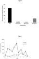
- Figure 1
- shows how polyferric sulphate treatment solution applied at an average rate of 200 mg Fe/L of farm dairy effluent can reduce the methane emission flux from treated effluent (TE) compared to untreated farm dairy effluent (FDE);
- Figure 2
- shows how polyferric sulphate treatment solution applied at an average rate of 200 mg Fe/L of farm dairy effluent can reduce the total amount of methane emitted over the 58-day period from treated effluent (TE) compared to untreated farm dairy effluent (FDE);
- Figure 3
- shows that polyferric sulphate applied at an average rate of 200 mg Fe/L of farm dairy effluent can reduce methane emissions (as shown in
Figures 1 and 2 ) without increasing hydrogen sulphide (H2S) emissions (in fact PFS significantly reduced the H2S emissions). - Figure 4a
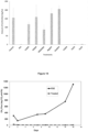
- shows that, in general, the total amount of methane emitted from farm dairy effluent (FDE) is inversely related to the rate of polyferric sulphate (PFS) used in the treatment. The statistically determined R2 value (i.e. 'the coefficient of determination') shown in the drawing is 0.9733; which is very close to the maximum value of 1.0 proving that there is a very strong relationship between the amount of methane emitted and the rate of polyferric sulphate applied in this experiment. The statistically fitted line shows that, in general, the higher the rate of PFS application then the lower the amount of methane emitted.
- Figure 4b
- shows the relationship between the rate of polyferric sulphate used and the percentage (%) reduction in the amount of methane emitted at that rate compared with the methane emissions in the untreated effluent. This relationship can be used to calculate the rate of PFS (or FS) that is required to achieve a desired percentage reduction in the amount of methane emitted.
- Figure 5
- shows that the methane emission flux from untreated farm dairy effluent (FDE) is reduced when polyferric sulphate is applied to treat the effluent at three different rates: (i) 210 mg Fe/L of FDE (i.e. the rate required to reduce the amount of methane emitted by > 90% from this effluent)), (ii) 105 mg Fe/L of FDE (i.e. 50% of the initial rate), and (iii) 53 mg Fe/L of FDE (i.e. 25% of the initial rate). Error bars are ± standard errors of the mean.
- Figure 6
- shows that the total amount of methane emitted from untreated FDE is reduced when the effluent is treated with PFS at all three rates: (i) 210 mg Fe/L of FDE (ii) 105 mg Fe/L of FDE, and (iii) 53 mg Fe/L of FDE. Error bars are ± standard errors of the mean.
- Figure 7
- shows that a single PFS treatment at a rate of 200 mg Fe/L of farm dairy effluent (FDE) on
day 1 can reduce the methane emission flux from the treated effluent (TE) for 36 days. Error bars are ± standard errors of the mean. - Figure 8
- shows that a single PFS treatment at a rate of 200 mg Fe/L of farm dairy effluent (FDE) on
day 1 can reduce the total amount of methane emitted from the treated effluent (TE) over the 36-day period. Error bars are ± standard errors of the mean. - Figure 9
- shows that multiple inputs of PFS at an average rate of 300 mg Fe/L of FDE over a 28 day period reduced the methane emission flux from the treated effluent (TE) and a mix of treated effluent and clarified water (MIX) for a further 28 days after the PFS treatment ceased. Error bars are ± standard errors of the mean.
- Figure 10
- shows that multiple inputs of PFS at an average rate of 300 mg Fe/L of FDE over a 28 day period reduced the total amount of methane emitted from the treated effluent (TE) and a mix of treated effluent and clarified water (MIX) over a 56 day period. Error bars are ± standard errors of the mean.
- Figure 11
- shows that treatment of FDE with ferric sulphate (FS) (i.e. the trivalent form of iron sulphate; Fe2(SO4)3) at a rate of 200 mg Fe/L of FDE is equally as effective in reducing the methane emission flux as treating FDE with polyferric sulphate (PFS) at a rate of 200 mg Fe/L of FDE. Error bars are ± standard errors of the mean.
- Figure 12
- shows that treatment of FDE with ferric sulphate (FS) (i.e. the trivalent form of iron sulphate; Fe2(SO4)3) at a rate of 200 mg Fe/L of FDE is equally as effective in reducing the total amount of methane emitted as treating FDE with polyferric sulphate (PFS) at a rate of 200 mg Fe/L of FDE. Error bars are ± standard errors of the mean.
- Figures 13a and 13b
- show that although the amount of methane emitted from FDE can be reduced by treating the FDE with calcium sulphate (CaSO4), potassium sulphate (K2SO4), aluminium sulphate (Al2(SO4)3), magnesium sulphate (MgSO4), and sodium sulphate (Na2SO4) (
Figure 13a ), none of these chemicals are as effective as PFS, and all these alternative sulphate chemicals continued to produce, or enhanced the production of, the toxic gas hydrogen sulphide (H2S), whilst PFS stopped the emission of hydrogen sulphide gasFigure 13b ); and the alternative iron chemical treatments of ferrous sulphate (i.e. the divalent form of iron sulphate; FeSO4), ferric chloride (FeCl3) and ferrous chloride (FeCl2) were not nearly as effective as polyferric sulphate (PFS) in reducing methane emission from treated effluent (Figure 13a ). - Figure 14
- shows that PFS is highly effective in reducing the methane emission flux from treated effluent (TE) compared to untreated FDE transferred to, and stored in, large 100,000 litre effluent storage tanks on a dairy farm. Average rate of PFS addition was 150 mg Fe/L of FDE.
- Figure 15
- shows that PFS is highly effective in reducing the total amount of methane emitted from treated effluent (TE) compared to untreated FDE transferred to, and stored in, large 100,000 litre effluent storage tanks on a dairy farm. Average rate of PFS addition was 150 mg Fe/L of FDE. The PFS treatment reduced the total amount of methane emitted by 98%.
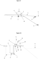
- Figure 16
- shows a schematic side view of an effluent methane mitigation treatment system where the effluent is pumped into a tank where it can be treated and mixed with FS or PFS before the mixture is transferred into a storage pond(s)/tank(s).
- Figure 17
- shows a schematic side view of an effluent methane mitigation treatment system where the ferric sulphate or polyferric sulphate is added directly into an effluent storage pond(s)/tank(s).
- Figure 18
- shows a schematic side view of an effluent methane mitigation treatment system where the ferric sulphate or polyferric sulphate is added into a sump tank where it is mixed with the effluent prior to delivery of the treated effluent into an effluent storage pond(s)/tank(s). The treatment system shown in this figure is considered likely to be the most effective and efficient system because of the effectiveness of the mixing system and the minimal amount of infrastructure required.
- A simulated animal effluent pond column study was conducted to determine the effect of adding a coagulant solution (polyferric sulphate) to treat farm dairy effluent collected from a farm. The study consisted of PVC pipes (1000 mm high x 150 mm in diameter) with endcaps at the base and detachable gas collection caps at the top of each column. These columns represented the physical dimensions of a column of effluent found in a typical farm dairy effluent pond. There were two treatments (untreated farm dairy effluent (FDE) vs. treated effluent (TE)) and seven replicate columns for each treatment. Farm dairy effluent was collected from the Lincoln University Dairy Farm and treated with a polyferric sulphate solution at a rate of 200 mg Fe/L of farm dairy effluent.
- Five hundred milliliters of untreated effluent (FDE), or treated effluent (TE), respectively were added to the replicate treatment columns every workday for one month (i.e. excluding weekends). Each addition raised the height of the liquid in the column by 25 mm and after one month the height of effluent in each column was 500mm. After one month, no more additions were made to the effluent columns, however, measurements continued for another 4 weeks.
- Gas sampling was conducted once a day (during the working week) using a standard procedure for gas sampling (Di et al., 2007). The gas caps were attached to each column and three gas samples were taken with 30-minute intervals between each sampling (i.e. at time = 0 mins, time = 30 mins and time = 60 mins). The gas lids were then removed until the next gas sampling occasion.
- The concentration of CH4 gas in each sample was determined using a gas chromatograph (GC) (Model 8610C, SRI Instruments, CA, USA) with an automated Gilson GX-271 auto sampler (Gilson Inc., MI, USA) coupled to a flame ionized detector (FID). The GC used three HayeSep D packed pre-columns, and two HayeSep D analytical columns. The carrier gases were H2 and air and the detector temperature setting was 370 °C. Hourly GHG emissions were calculated based on the rate of increase in GHG concentration in the chamber corrected for temperature and the ratio of surface area to headspace volume (Richards et al. 2014). The rate of gas emission was calculated using the slope of headspace gas concentration change from the samples collected on each sampling occasion (Hutchinson & Mosier 1981) and the methane emission flux (i.e. gas emission rate per unit area) was calculated using this data . Cumulative emissions were calculated by integrating the measured daily fluxes for the whole experimental measurement period.The results surprisingly showed that treating FDE with polyferric sulphate solution to produce treated effluent (TE) unexpectedly reduced the methane emission flux from the TE compared to the untreated FDE over the 58-day period of the trial (
Figure 1 ). - The results showed that treating farm dairy effluent with a polyferric sulphate solution reduced the total amount of methane emitted over a 58-day period by around 90% compared to the untreated farm dairy effluent (
Figure 2 ). This reduction in methane emission can be achieved without increasing hydrogen sulphide (H2S) emissions (in fact PFS significantly reduced H2S emissions) (Figure 3 ). - Following on from this surprising discovery, the inventors conducted a series of additional experiments to verify the results of
Experiment # 1 and to test the effectiveness of PFS and ferric sulphate (FS) to reduce methane emissions from FDE at a larger scale and on a dairy farm. - The objective of
Experiment 2 was to determine if there was a relationship between the rate of PFS treatment of FDE and the amount of methane emitted. The experiment was conducted using 1.5 L glass jars which were filled with 1 L of farm dairy effluent collected from the Lincoln University Dairy Farm. Eleven rates of PFS were applied in 25 mg Fe/L increments, ranging from 0 up to 250 mg Fe/L. There were four replicates of each treatment set out in a randomised block design in the laboratory. - Each glass jar had a detachable screw cap with rubber septum that allowed gas samples to be collected from the headspace above the effluent using a standard procedure for gas sampling (Di et al. 2007) (as described above in Experiment 1).
- The results show that there is a strong inverse relationship between the amount of methane (CH4) emitted and the rate of polyferric sulphate (PFS) treatment (i.e. the higher the rate of PFS application the lower the amount of CH4 emitted (
Figure 4a ). - The relationship of the data shown in
Figure 4b can be used to calculate the rate of PFS (or FS) required to achieve a specific percentage reduction in the total amount of methane emitted. In this experiment, the original turbidity of the effluent was measured to be approximately 2,500 NTU and this information can be used in combination with the data inFigure 4b to calculate the rate of FS (or FS) required, as shown by way of example in Table 1 below):Table 1 Desired percentage reduction in the amount of methane emitted (%) Formulae for determining dosage of FS or PFS that needs to be added to the effluent (mg Fe/L effluent) >95% reduction Dosage = 0.1 x NTU value of effluent 90 to 95% reduction Dosage= 0.08 x NTU value of effluent 80 to 89% reduction Dosage = 0.06 x NTU value of effluent 60 to 79% reduction Dosage= 0.04 x NTU value of effluent 40 to 59% reduction Dosage= 0.024 x NTU value of effluent 20 to 39% reduction Dosage = 0.013 x NTU value of effluent - The objective of
Experiment 3 was to determine the effect of four different rates of PFS treatment of FDE on methane emissions under simulated effluent pond conditions. The experiment used the same microcosm equipment and gas sampling procedures described above for Experiment1. Farm dairy effluent was collected from the Lincoln University Dairy Farm each day (excluding weekends).The average amount of PFS added to each batch of effluent was 210 ± 14 mg Fe/L of FDE. There were four treatments: (i) untreated FDE, (ii) effluent treated with PFS at the rate calculated to be required to achieve > 90% reduction in the total amount of methane emitted (210 mg Fe/L), (iii) effluent treated at half the initial rate (105 mg Fe/L), and (iv) effluent treated at quarter the initial rate (52 mg Fe/L). There were three replicate columns per treatment set out in a randomised block design. Two litres of each treated effluent batch were added to the replicated columns twice per week for one month. Gas samples were collected twice per week for 28 days. The concentration of CH4 gas was determined using gas chromatography (as described above). - The results of this laboratory microcosm study shows that the methane emission flux from untreated farm dairy effluent (FDE) was reduced when the effluent was treated with polyferric sulphate (TE) at all three rates and that the size of the reduction depended on the rate of PFS applied in the treatment (
Figure 5 ). The results of the experiment also shows that the total amount of methane emitted from untreated FDE was reduced when the effluent was treated with PFS (TE) at all three rates and that the size of the reduction depended on the rate of PFS applied in the treatment (Figure 6 ). - The objective of
Experiment 4 was to 'scale up' the measurements to determine the effect of PFS treatment of FDE on CH4 emissions using larger (3.5 m deep x 0.5 m diameter) PVC pipes installed on a farm. These large columns represent vertical 'mesocosms' of effluent that would be present in a typical farm dairy effluent pond; with the advantage that replicated treatments could be compared. Each column had an end cap glued onto the bottom and a water trough collar attached to the top. The gas capture equipment was identical to that used for gas capture in nitrous oxide measurement research (Di et al. 2007) and involved placing an insulated gas capture chamber over the column with the edge of the chamber inserted into the water trough (thus giving an airtight gas seal). Each gas collection chamber had a small fan which circulated the gas within the sealed head space of the column. - There were two treatments: (i) untreated FDE and (ii) FDE treated with PFS (TE). There were seven replicates of each treatment set out in a randomised block design. Five hundred and sixty litres of farm dairy effluent were pumped from the FDE storage pond on Lincoln University Dairy Farm into each column leaving a head space height of c. 10 cm. The turbidity of the FDE was measured to be approximately 2,200 NTU and therefore, based on the formula given in Table 1, the PFS solution was added at a rate of 200 mg Fe/L of FDE. The PFS treatment was mixed into the effluent in the PVC pipe for two minutes using a hand-held electric drill fitted with a paddle stirrer.
- The results show that a single PFS treatment of farm dairy effluent (FDE) on
day 1 can reduce the methane emission flux from the treated effluent (TE) for 36 days (Figure 7 ). - The results also show that a single PFS treatment of farm dairy effluent (FDE) on
day 1 can significantly reduce the total amount of methane emitted from the treated effluent (TE) for 36 days (Figure 8 ). - The objective of
experiment 5 was to determine the effect of adding PFS on CH4 emissions during, and after, sequential additions of effluent into the mesocosm columns (i.e. simulating standard practice on a farm where effluent is treated each day and pumped into the effluent storage pond). There were three treatments: (i) untreated FDE, (ii) treated effluent (TE) and, (iii) a mixture of treated effluent and clarified water (MIX) that was collected immediately after the PFS was mixed into the effluent but before settling of the TE had occurred. There were four replicates of each treatment set out in a randomised block design. - Fifty-six litres of each effluent treatment were transferred into each replicated treatment column twice per week for five weeks, until the columns were nearly full (560 L). Untreated FDE was pumped into the mesocosm columns from the effluent sump at the dairy shed on the farm.The PFS solution was added automatically by acomputer-controlled pump (the average rate used for the ten batches was 300 ± 14 mg Fe/L). After mixing for 15 minutes, 56 L of the mixture (MIX) was then pumped into each treatment replicate column. The mixing tank was then allowed to settle for three hours to enable the flocculated particles in the treated effluent to settle to the bottom of the tank; 56 L of TE was then pumped from the bottom of the tank into each replicated treatment column.
- Gas sampling was conducted twice per week using the standard procedure for gas sampling described earlier. Once the gas caps were attached to each column, three gas samples were taken with 30-minute intervals between each sampling (i.e. at time = 0 minutes, time = 30 minutes, and time = 60 minutes). The gas caps were then removed until the next gas sampling occasion. The concentration of CH4 gas was determined using gas chromatography (as described earlier).
- The results of
Experiment 5 show that multiple inputs of PFS over a 28 day period reduced the methane emission flux from the treated effluent (TE) and a mix of treated effluent and clarified water (MIX) for a further 28 day without any further input of PFS being required (Figure 9 ). - The results of
field mesocosm Experiment 5 also show that multiple inputs of PFS over a 28 day period significantly reduced the total amount of methane emitted from the treated effluent (TE) and a mix of treated effluent and clarified water (MIX) by > 90% over a 56 day period (Figure 10 ). - The objective of
Experiment 6 was to compare the effectiveness of ferric sulphate (FS) versus polyferric sulphate (PFS) to reduce methane emissions from treated effluent.Experiment 6 was conducted using the same large (3.5 m deep x 0.5 m diameter) PVC pipes described inExperiment 5. The gas capture equipment and measurement process were also identical to that described inExperiment 5. - There were three treatments: (i) untreated FDE; (ii) TE produced using PFS and (iii) TE produced using FS. There were four replicates of each treatment set out in a randomised block design. Five hundred and sixty litres of farm dairy effluent were pumped from the FDE storage pond on Lincoln University Dairy Farm into each column leaving a head space height of 10 cm.
- The same rate of PFS and FS was used (200 mg Fe/L of FDE). The PFS and FS solution was mixed into the effluent for two minutes using a handheld electric drill fitted with a paddle stirrer.
- Results of
Experiment 6 show that treatment of FDE with ferric sulphate (FS) (i.e. the trivalent form of iron sulphate: Fe2(SO4)3) is equally as effective in reducing the methane emission flux as treating FDE with polyferric sulphate (PFS) (Figure 11 ). - Results of
Experiment 6 show that treatment of FDE with ferric sulphate (FS) (i.e. the trivalent form of iron sulphate; Fe2(SO4)3) is equally as effective in reducing the total amount of methane emitted as treating FDE with polyferric sulphate (PFS) (Figure 12 ). - The objective of
Experiment 7 was to measure the effect of different sulphate and/or iron compounds on emissions of methane and hydrogen sulphide gases from treated effluent. The experiment was conducted using the same 1.5 L glass jars and methods of measurement described inExperiment 2 above. There were 10 treatments: (i) untreated FDE, (ii) PFS treated effluent, (iii) calcium sulphate (CaSO4) treated effluent, (iv) potassium sulphate (K2SO4) treated effluent, (v) aluminium sulphate (Al2(SO4)3) treated effluent, (vi) magnesium sulphate (MgSO4) treated effluent, (vii) sodium sulphate (Na2SO4) treated effluent, (viii), ferrous sulphate (i.e. the divalent form of iron sulphate) (FeSO4) treated effluent, (ix) ferric chloride (FeCl3) treated effluent, and (x) ferrous chloride (FeCl2) treated effluent. The sulphate treatment chemicals were all used at the same rate of sulphate as applied in the PFS treatment (326 mg SO4/L) and the iron treatment chemicals were all used at the same rate of iron as applied in the PFS treatment (133 mg Fe/L). - The results show that although the amount of methane emitted from FDE can be reduced by treating the FDE with calcium sulphate (CaSO4), potassium sulphate (K2SO4), aluminium sulphate (Al2(SO4)3), magnesium sulphate (MgSO4), sodium sulphate (Na2SO4), (
Figure 13 a) none of these chemicals were as effective as PFS and all these sulphate treatment chemicals continued to produce, or enhanced the production of, the toxic gas hydrogen sulphide (H2S), whilst PFS reduced the emission of hydrogen sulphide (Figure 13 b) . - The results also show that the alternative iron treatments; ferrous sulphate (i.e. the divalent form of iron sulphate: FeSO4), ferric chloride (FeCl3) and ferrous chloride (FeCl2) were not nearly as effective as polyferric sulphate (PFS) in reducing methane emission from treated effluent (
Figure 13 a) . - The objective of
Experiment 8 was to increase the scale of measurements to represent farm scale conditions. This was achieved by measuring the effect of PFS treatment of FDE on CH4 emissions from effluent stored in typical effluent storage tanks used on a dairy farm. Two commercially available 100,000 L effluent storage tanks were constructed on the Lincoln University Research Dairy Farm. One tank was used to store untreated FDE and the other tank used to store treated effluent (TE). A gas tight roof (with vents) was installed over the top of each tank which allowed the gas emissions to be captured and sampled when the vents were closed. During the time period between sampling events, the vents were left open to ensure that typical effluent tank storage conditions occurred. - These 100,000 litre storage tanks were filled by transferring five batches of approximately 20,000 L of untreated FDE directly from the existing farm effluent sump into the 'untreated FDE tank' and by transferring five batches of approximately 20,000 L of treated effluent into the TE tank. The tanks were filled in sequential batches to ensure that, as far as possible, the effluent composition was similar between the untreated batch and the treated batch produced each day on the farm. The average turbidity of the effluent was 1,400 NTU and the average rate of PFS treatment for each 20,000 L batch was therefore calculated (according to Table 1) to be 150 mg Fe/L of FDE.
- Gas sampling was conducted twice per week by closing the vents on the top of each tank allowing the gas emissions to be captured and sampled. Once the vents were closed, three gas samples were taken with 90-minute intervals between each sampling (i.e. at time = 0 minutes, time = 90 minutes, and time = 180 minutes). The vents were then left open until the next gas sampling occasion. The concentration of CH4 gas was determined using gas chromatography (as described earlier).
- The results of
Experiment 8 show that PFS is highly effective in reducing the methane emission flux from treated effluent (TE) compared to untreated FDE transferred to, and stored in, large 100,000 litre effluent storage tanks on a dairy farm (Figure 14 ). - The results of
Experiment 8 also show that PFS is highly effective in reducing the total amount of methane emitted from treated effluent (TE) compared to untreated FDE transferred to, and stored in, large 100,000 litre effluent storage tanks on a dairy farm (Figure. 15 ).The PFS treatment reduced the total amount of methane emitted from the effluent by around 98% (Figure 15 ). - In
Figure 16 there is shown an animal effluent methane mitigation treatment system where the effluent is pumped from an effluent catchment area through apipe 1 into an existing ornew sump tank 2 which has amixer 3 for mixing the treatment chemical (FS or PFS) into the effluent. The FS or PFS is stored in achemical storage tank 4 and the treatment solution is delivered into the mixing tank by apump 5. There is aturbidity sensor 6 in the mixing tank to measure the turbidity of the effluent and apipe 7 that directs all of the treated effluent from the mixing tank into an effluent storage pond(s)/tank(s) 8 via anoptional pump 9 or through gravity. The treatment system is controlled by aPLC 10 that has data/control cables 11 to the electronic component parts of the treatment system. The amount of PFS or FS that is required to achieve a specific reduction in the amount of methane emitted is computed by the PLC based on the data presented inFigure 4b and in Table 1 (shown above). - In
Figure 17 there is shown an animal effluent methane mitigation treatment system where the treatment chemical (FS or PFS) is delivered by apump 1 from achemical storage tank 2 through apipe 3 directly into an effluent storage pond/tank 4, with a or without astirrer 5, and the amount of FS or PFS delivered is controlled by aPLC 6 connected to aflow meter 7 in the effluentpond delivery pipe 8, or anothersensor 9 in the pond, that detects the volume of the latest batch of fresh effluent added into the pond and sends data to the PLC bydata cable 10 to control the delivery of FS or PFS to treat the measured volume of fresh effluent added into the pond/tank. The amount of PFS or FS that is required to achieve a specific reduction in the amount of methane emitted is computed by the PLC based on the data presented inFigure 4b and in Table 1 (shown above). - In
Figure 18 there is shown an animal effluent methane mitigation treatment system where the effluent is transferred via apipe 1 from an effluent catchment area (e.g. yard) into asump tank 2 where the treatment chemical (FS or PFS) is added from achemical storage tank 3 via apump 4 anddelivery pipe 5. The chemical is mixed into the effluent using amixer 6 in the sump tank and the treated effluent is transferred by apump 7 from the sump tank through apipe 8 to an effluent storage pond(s)/tank(s) 9. There is aturbidity sensor 10 in the pipe to measure the turbidity of the effluent and this data can be used by thePLC 11 to control the amount of treatment chemical added to the effluent. The amount of PFS or FS that is required to achieve a specific reduction in the amount of methane emitted is computed by the PLC based on the data presented inFigure 4b and in Table 1 (shown above). - There is a
flow meter 12 in the pipe to measure the amount of effluent pumped to the pond and this data is sent bydata cable 13 to the PLC to control the amount of FS or PFS added to the effluent sump tank. The ferric sulphate or polyferric sulphate is added into the sump tank when a prescribed amount of effluent (e.g. 5,000 L) has been pumped out of the sump tank into the storage pond(s)/tank(s), so that the ferric sulphate or polyferric sulphate can react with an equivalent amount of fresh effluent that drains into, or is pumped into, the sump tank. - The present invention has application to cattle, in particular, but not limited to, dairy cows.
- However, it should be appreciated, that the present invention can also be used in relation to other agricultural animals, which are grouped in areas where liquid effluent is going to be collected and needs to be stored or disposed.
- The present invention concerns the surprising discovery that adding ferric sulphate or polyferric sulphate into liquid animal effluent - which is contrary to the art of human municipal wastewater treatment which wants to reduce the ionic sulphur content in effluent to prevent hydrogen sulphide production (HulshoffPol et al., 1998, Metcalf and Eddy, 2014), can significantly reduce methane emissions.
- It is important, however, to note that the (human) wastewater treatment engineering literature actually teaches that sulphate can cause the 'failure' of the anaerobic process of organic matter digestion used in many wastewater treatment facilities (HulshoffPol et al., 1998, Metcalf and Eddy, 2014)). Therefore, it was not expected that adding ferric sulphate or polyferric sulphate could be used to reduce methane emissions from animal effluent - whilst not compromising the effective treatment of effluent.
- The main reason that the wastewater treatment plant engineers would not want large amounts of sulphate in the anaerobic treatment plant is that it inhibits the full anaerobic breakdown of organic matter in the sewage water.
- This is important because the predominant method of disposal of treated wastewater effluent is to discharge it into surface water (rivers, lakes or the ocean) (e.g. Christchurch City Council, 2019; Brittania, 2019). When treated sewage wastewater eventually goes into rivers, lakes or the ocean, any organic matter remaining in the wastewater will deplete the river, lake or ocean of oxygen (due to the Biochemical Oxygen Demand (BOD) of the organic material) causing death of fish and other aquatic life (MFE, 2019b). The BOD of the treated effluent must be kept low to avoid adverse impacts on the receiving water (MFE 2019b) thus the anaerobic process must not be inhibited by the presence of sulphate.
- Thus, wastewater treatment plants do not want to add sulphates including ferric sulphate or polyferric sulphate to the sewage water.
- HulshoffPol et al. (1998) specifically states that the presence of sulphate "can cause severe problems when sulphate containing organic wastewater is treated anaerobically". This is of the utmost importance, because free hydrogen sulphide (H2S) concentrations can cause wastewater treatment process failure due to sulphide toxicity.
- According to HulshoffPol et al. (1998) gaseous and dissolved sulphides cause physical-chemical (corrosion, odour, increased effluent chemical oxygen demand) or biological (toxicity) constraints, which may lead to process failure.
- Therefore, attempts have been made to remove, or suppress, the effects of sulphate in wastewater treatment plants. For example, the strategies currently available to do this include: i) removal of the organic matter, ii) removal of sulphate or iii) removal of both - (HulshofPol et al. 1998).
- Zub et al. (2008) also provide a list of strategies to remove sulphur containing compounds from wastewater prior to treatment in order to ensure that the biological process of wastewater treatment is not adversely affected.
- The results of our experiments show that adding polyferric sulphate or ferric sulphate can reduce methane emissions from animal effluent without increasing hydrogen sulphide emissions (
Figures 3 and13b ). In fact, the experimental data show that the hydrogen sulphide emissions are significantly reduced when animal effluent is treated with polyferric sulphate. This demonstrates the utility of the invention because polyferric sulphate or ferric sulphate can be used to reduce methane emissions from the animal effluent without the risk of increasing hydrogen sulphide emissions. - Treating animal effluent with polyferric sulphate on a farm is different to treating sewage wastewater because the treated animal effluent is generally applied onto the land; where there is much less risk of impact in terms of Biochemical Oxygen Demand (BOD) compared with human effluent which is discharged into surface water as discussed earlier..
- So, the present invention provides a previously unforeseen opportunity to inhibit the anaerobic breakdown process in animal effluent before methane gets produced whilst the sewage wastewater engineers cannot interfere with the anaerobic process by adding ferric sulphate or polyferric sulphate.
- The present invention also provides an opportunity to return more carbon to the soil if we inhibit the anaerobic process before it produces methane (i.e. rather than allow the carbon to be lost to the atmosphere as methane causing greenhouse gas emissions). As the treated effluent/ sludge has organic matter therein containing a large amount of readily available carbon (in the form of simple organic compounds such as acetic acid) which can be applied to the land. Why lose the carbon into the atmosphere if we can recycle it back into the soil?
- The PFS or FS may be added to the FDE as in a powder or liquid form.
- The amount of ferric sulphate or polyferric sulphate that is added to the liquid animal effluent will depend on:
- the type of animal effluent; and
- the solids content (especially the organic matter content) of the effluent (turbidity being used as a measurement/indicator thereof).
- The polyferric sulphate or ferric sulphate may be added to the liquid animal effluent either whilst in transit to, or once delivered to:
- a pond,
- lagoon,
- tank,
- storage or transportation vessel.
- The source of liquid animal effluent may generally be a cattle yard, or a milking shed/parlor for dairy cows.
- However, the source of liquid animal effluent should not be limited and may include one or more of the following:
- stock lanes (or stock races);
- stock feed pads
- stock housing facilities;
- cattle trucks;
- sheep trucks;
- effluent disposal tanks (e.g. sheep/cattle trucks); and
- animal holding pens or yards.
- Aspects of the present invention have been described by way of example only and it should be appreciated that modifications and additions may be made thereto without departing from the scope thereof as defined in the appended claims.
- Brittania (2019). Wastewater treatment for pollution control.
- https://www.britannica.com/explore/savingearth/wastewater-treatment/
- Christchurch City Council (2019). Christchurch City Council Waste Water Treatment Plant Discharge Consent. https://www.ccc.govt.nz/services/water-and-drainage/wastewater/treatment-plants/christchurch-wastewater-treatment-plant/discharge-consent-monitoring .
- Di, H.J., Cameron, K.C., Sherlock, R.R. (2007). Comparison of the effectiveness of a nitrification inhibitor, dicyandiamide, in reducing nitrous oxide emissions in four different soils under different climatic and management conditions. Soil Use and Management, 23: 1-9.
- Gluckman, P. (2018). Mitigating agricultural greenhouse gas emissions: Strategies for meeting New Zealand's goals. https://www.pmcsa.org.nz/wp-content/uploads/Mitigating-agricultural-GHG-emissions-Strategies-for-meeting-NZs-goals.pdf
- HulshoffPol, L.W., Lens, P., Stams, A., Lettinga, G. (1998). Anaerobic treatment of sulphate-rich wastewaters. Biodegradation, 9: 213-224.
- Hutchinson GL, Mosier AR. (1981). Improved soil cover method for field measurement of nitrous oxide fluxes. Soil Use and Management. 2:311-315.
- Laubach, J., Heubeck, S., Pratt, C., Woodward, K.B., Guieysse, B., van der weerden, T.J., Chung, M.L., Shilton, A.N., Craggs, R.J. (2015). Review of greenhouse gas emissions for the storage and land application of farm dairy effluent. New Zealand Journal of Agricultural Research, 58 (2): 203-233.
- Metcalf and Eddy. (2014). Wastewater Engineering. McGraw-Hill, New York.
- MFE (2019a). New Zealand's Greenhouse Gas Inventory 1990 - 2017. Ministry for the Environment, Wellington, New Zealand. https://www.mfe.govt.nz/climate-chanqe/state-of-our-atmosphere-and-climate/new-zealands-greenhouse-gas-inventory
- MFE (2019b). Sustainable wastewater management.
- https://www.mfe.govt.nz/publications/waste/sustainable-wastewater-management-handbook-smaller-communities-part-1-0
- MPI (2012). Revised methane emission factors and parameters for dairy effluent ponds. Final Report Contract: 12215 (IR-H 13). Prepared by Pratt, C., Walcroft, A. (Landcare Research);
- Shilton, A., Guieysse, B., Chung, M. (Massey University); Craggs, R., Heubeck, S. (National Institute of Atmospheric Research). https://www.mpi.govt.nz/dmsdocument/14506/direct
- MPI (2014). Review of gaseous emissions of methane, nitrous oxide and ammonia, and nitrate leaching to water, from farm dairy effluent storage and application to land. MPI Technical Paper No: 2018/39. https://www.agriculture.govt.nz/dmsdocument/30131/direct
- MPI (2017). Trends in Dairy Effluent Management Final report. Ministry for Primary Industries Technical Paper Number 2018/70. Prepared by Rollo, M., Ledgard, S., Longhurst, B., AgResearch. http://www.mpi.govt.nz/news-and-resources/publications
- CZub, S., Kurrisso, Y., Menert, A. Blonskaja, V. (2008). Combined biological treatment of high-sulphate wastewater from yeast production. Water and Environment Journal 22, 274-286.
Claims (1)
- A method to reduce methane emissions from liquid animal effluent relative to untreated liquid animal effluent using ferric sulphate or polyferric sulphate via a dose of ferric sulphate or polyferric sulphate, expressed in mg Fe/L effluent, calculated from the measurement of the turbidity, expressed in NTU, of the effluent to be treated to achieve a desired percentage reduction in the amount of methane emitted, wherein the dose required for a desired percentage reduction is determined by the formulae detailed in the following table:
Desired percentage reduction in the amount of methane emitted (%) Formulae for determining dosage of FS or PFS that needs to be added to the effluent (mg Fe/L effluent) >95% reduction Dosage = 0.1 x NTU value of effluent 90 to 95% reduction Dosage= 0.08 x NTU value of effluent 80 to 89% reduction Dosage = 0.06 x NTU value of effluent 60 to 79% reduction Dosage= 0.04 x NTU value of effluent 40 to 59% reduction Dosage= 0.024 x NTU value of effluent 20 to 39% reduction Dosage = 0.013 x NTU value of effluent
Applications Claiming Priority (2)
| Application Number | Priority Date | Filing Date | Title |
|---|---|---|---|
| NZ75781719 | 2019-10-10 | ||
| PCT/NZ2020/050123 WO2021071367A1 (en) | 2019-10-10 | 2020-10-12 | Improvements in and relating to effluent |
Publications (3)
| Publication Number | Publication Date |
|---|---|
| EP3973068A1 EP3973068A1 (en) | 2022-03-30 |
| EP3973068A4 EP3973068A4 (en) | 2023-06-07 |
| EP3973068B1 true EP3973068B1 (en) | 2024-07-17 |
Family
ID=75436758
Family Applications (1)
| Application Number | Title | Priority Date | Filing Date |
|---|---|---|---|
| EP20873360.0A Active EP3973068B1 (en) | 2019-10-10 | 2020-10-12 | Improvements in and relating to effluent |
Country Status (12)
| Country | Link |
|---|---|
| US (1) | US12209038B2 (en) |
| EP (1) | EP3973068B1 (en) |
| AU (1) | AU2020364915B2 (en) |
| CA (1) | CA3143955C (en) |
| DK (1) | DK3973068T3 (en) |
| ES (1) | ES2993180T3 (en) |
| GB (2) | GB2598256A (en) |
| HU (1) | HUE067570T2 (en) |
| IE (2) | IE20200300A1 (en) |
| PL (1) | PL3973068T3 (en) |
| PT (1) | PT3973068T (en) |
| WO (1) | WO2021071367A1 (en) |
Families Citing this family (1)
| Publication number | Priority date | Publication date | Assignee | Title |
|---|---|---|---|---|
| AU2024216848B2 (en) * | 2023-02-07 | 2025-10-16 | Lincoln University | Improvements in and relating to effluent and treatment of same |
Citations (1)
| Publication number | Priority date | Publication date | Assignee | Title |
|---|---|---|---|---|
| RU2644749C1 (en) * | 2017-06-19 | 2018-02-13 | Михаил Иванович Голубенко | Lysimeter |
Family Cites Families (8)
| Publication number | Priority date | Publication date | Assignee | Title |
|---|---|---|---|---|
| DE2638957C3 (en) * | 1976-08-28 | 1980-02-14 | Hoechst Ag, 6000 Frankfurt | Odor inhibitor |
| KR100407554B1 (en) * | 1999-05-29 | 2003-12-01 | 최주식 | A disposal method of pig ordure |
| KR100523338B1 (en) * | 2003-09-09 | 2005-10-24 | 한국과학기술연구원 | Method for treating and reusing high-strength organic wastewater |
| US20060005784A1 (en) * | 2004-07-08 | 2006-01-12 | Lind Christopher B | Environmental control of confined animal rearing facilities with liquid iron compounds |
| US20110044927A1 (en) * | 2004-08-26 | 2011-02-24 | Aceto Corporation | Odor abatement of organic waste |
| US20160076057A1 (en) * | 2014-09-17 | 2016-03-17 | Innovative Environmental Technologies, Inc. | Inhibition of methane and hydrogen sulfide production in anaerobic digester animal farms, landfills, sediments and sewer systems |
| NZ743564A (en) * | 2016-06-20 | 2019-07-26 | Ravensdown Ltd | Improvements in and relating to animal effluent treatment system |
| CN107055723A (en) * | 2017-04-25 | 2017-08-18 | 四川蓉泰环保技术有限公司 | Livestock breeding wastewater treatment agent and the equipment using the medicament |
-
2020
- 2020-10-12 AU AU2020364915A patent/AU2020364915B2/en active Active
- 2020-10-12 WO PCT/NZ2020/050123 patent/WO2021071367A1/en not_active Ceased
- 2020-10-12 PT PT208733600T patent/PT3973068T/en unknown
- 2020-10-12 EP EP20873360.0A patent/EP3973068B1/en active Active
- 2020-10-12 CA CA3143955A patent/CA3143955C/en active Active
- 2020-10-12 HU HUE20873360A patent/HUE067570T2/en unknown
- 2020-10-12 IE IE20200300A patent/IE20200300A1/en unknown
- 2020-10-12 IE IE20200304A patent/IE20200304A2/en not_active IP Right Cessation
- 2020-10-12 ES ES20873360T patent/ES2993180T3/en active Active
- 2020-10-12 US US17/596,672 patent/US12209038B2/en active Active
- 2020-10-12 GB GB2117425.5A patent/GB2598256A/en not_active Withdrawn
- 2020-10-12 PL PL20873360.0T patent/PL3973068T3/en unknown
- 2020-10-12 DK DK20873360.0T patent/DK3973068T3/en active
- 2020-10-12 GB GBGB2117425.5D patent/GB202117425D0/en active Pending
Patent Citations (1)
| Publication number | Priority date | Publication date | Assignee | Title |
|---|---|---|---|---|
| RU2644749C1 (en) * | 2017-06-19 | 2018-02-13 | Михаил Иванович Голубенко | Lysimeter |
Also Published As
| Publication number | Publication date |
|---|---|
| US12209038B2 (en) | 2025-01-28 |
| EP3973068A1 (en) | 2022-03-30 |
| IE20200304A2 (en) | 2022-11-09 |
| ES2993180T3 (en) | 2024-12-23 |
| CA3143955A1 (en) | 2021-04-15 |
| WO2021071367A1 (en) | 2021-04-15 |
| AU2020364915B2 (en) | 2021-12-23 |
| DK3973068T3 (en) | 2024-08-05 |
| PL3973068T3 (en) | 2024-11-12 |
| PT3973068T (en) | 2024-07-26 |
| IE20200300A1 (en) | 2022-08-03 |
| GB202117425D0 (en) | 2022-01-19 |
| GB2598256A (en) | 2022-02-23 |
| EP3973068A4 (en) | 2023-06-07 |
| US20230183109A1 (en) | 2023-06-15 |
| CA3143955C (en) | 2023-02-07 |
| HUE067570T2 (en) | 2024-10-28 |
| AU2020364915A1 (en) | 2021-11-11 |
Similar Documents
| Publication | Publication Date | Title |
|---|---|---|
| KR20130103550A (en) | Biological purification agent, biological purification system and biological purification method for water to be treated | |
| Cameron et al. | Discovery of a new method to reduce methane emissions from farm dairy effluent | |
| US12209038B2 (en) | Effluent | |
| CN114262128A (en) | Treatment of Black and Smelly Inland River by Encapsulating Microorganisms and Compound Functional Minerals | |
| US11767248B2 (en) | Process and apparatus for the treatment of organic feedstock | |
| Bawa et al. | Water Quality Assessment of Godavari River at Nashik, India: Impact of Sewage and Industrial Wastewater. | |
| NZ791413A (en) | Improvements in and relating to effluent | |
| Zhu et al. | Raising pH by low–level aeration for soluble phosphorus removal of swine manure | |
| NZ769237A (en) | Improvements in and relating to effluent | |
| US20250178944A1 (en) | Improvements in and relating to effluent and treatment of same | |
| Ngare et al. | The Quality of Kiserian Slaughterhouses’ Effluent and Its Implication on Kiserian Dam Water in Kajiado County, Kenya | |
| Moșneang et al. | An analysis of water samples surrounding swine farms in Timiș County-a practical guide. | |
| Popa et al. | Types of treatment plants for livestock wastewater | |
| Abdalla Mohamed | Optimizing dairy farmyard infrastructure for the management and treatment of dairy soiled water | |
| NEAGU | Degree of water eutrophication in the terminal basin of the Danube. Case study. | |
| Abba et al. | EFFECTS OF POULTRY CONCENTRATED ANIMAL FEEDING OPERATIONS ON SOIL, WATER AND AIR: A CASE OF YEPWA FARM LTD YOLA, ADAMAWA STATE | |
| Shi | Mineral fertiliser equivalence value of dairy processing waste and derived strubias products | |
| Iyama et al. | Assessment of Nutri-Chemical Concentration Levels of Wastewater from Drains Adjacent Cement and Associated Factories in Port Harcourt, Nigeria | |
| Duerschner | Effect of Swine Manure Pit Additives and Facility Disinfectants on the Fate of Antibiotics and Manure Composition During Simulated Swine Manure Slurry Storage | |
| Murnane | Combined zeolite and chemical amendments mixed with agricultural wastes to reduce surface and leaching losses of nutrients and greenhouse gas emissions, and biofilter treatment of dairy soiled water | |
| Mahimainathan | A study on the vermicomposting of dewatered dairy waste | |
| STR4TEGIES | B. Sc., University of Calgary, 1996 | |
| Graham | Phosphorus Transport from a Field Receiving Long-Term Liquid Dairy Manure Application in a Karst Landscape. | |
| Neagu | Degree of charge with nutrients of waste water from a meat industrialization unit. Case study. | |
| Kostadinova et al. | Agroecological assessment of wastewater and sludge from Municipal Wastewater Treatment Plant by content of nutrient inputs. |
Legal Events
| Date | Code | Title | Description |
|---|---|---|---|
| STAA | Information on the status of an ep patent application or granted ep patent |
Free format text: STATUS: UNKNOWN |
|
| STAA | Information on the status of an ep patent application or granted ep patent |
Free format text: STATUS: THE INTERNATIONAL PUBLICATION HAS BEEN MADE |
|
| PUAI | Public reference made under article 153(3) epc to a published international application that has entered the european phase |
Free format text: ORIGINAL CODE: 0009012 |
|
| STAA | Information on the status of an ep patent application or granted ep patent |
Free format text: STATUS: REQUEST FOR EXAMINATION WAS MADE |
|
| 17P | Request for examination filed |
Effective date: 20211215 |
|
| AK | Designated contracting states |
Kind code of ref document: A1 Designated state(s): AL AT BE BG CH CY CZ DE DK EE ES FI FR GB GR HR HU IE IS IT LI LT LU LV MC MK MT NL NO PL PT RO RS SE SI SK SM TR |
|
| DAV | Request for validation of the european patent (deleted) | ||
| DAX | Request for extension of the european patent (deleted) | ||
| REG | Reference to a national code |
Ref legal event code: R079 Ipc: C02F0001520000 Ref country code: DE Ref document number: 602020034286 Country of ref document: DE Free format text: PREVIOUS MAIN CLASS: C12P0005020000 |
|
| A4 | Supplementary search report drawn up and despatched |
Effective date: 20230510 |
|
| RIC1 | Information provided on ipc code assigned before grant |
Ipc: C02F 101/10 20060101ALN20230503BHEP Ipc: C02F 101/32 20060101ALN20230503BHEP Ipc: C02F 103/20 20060101ALN20230503BHEP Ipc: A01C 3/02 20060101ALN20230503BHEP Ipc: A01K 1/01 20060101ALN20230503BHEP Ipc: C02F 11/00 20060101ALI20230503BHEP Ipc: C12P 5/02 20060101ALI20230503BHEP Ipc: C02F 1/52 20060101AFI20230503BHEP |
|
| P01 | Opt-out of the competence of the unified patent court (upc) registered |
Effective date: 20230419 |
|
| STAA | Information on the status of an ep patent application or granted ep patent |
Free format text: STATUS: EXAMINATION IS IN PROGRESS |
|
| 17Q | First examination report despatched |
Effective date: 20230929 |
|
| GRAP | Despatch of communication of intention to grant a patent |
Free format text: ORIGINAL CODE: EPIDOSNIGR1 |
|
| STAA | Information on the status of an ep patent application or granted ep patent |
Free format text: STATUS: GRANT OF PATENT IS INTENDED |
|
| RIC1 | Information provided on ipc code assigned before grant |
Ipc: C02F 101/10 20060101ALN20240328BHEP Ipc: C02F 101/32 20060101ALN20240328BHEP Ipc: C02F 103/20 20060101ALN20240328BHEP Ipc: A01C 3/02 20060101ALN20240328BHEP Ipc: A01K 1/01 20060101ALN20240328BHEP Ipc: C02F 11/00 20060101ALI20240328BHEP Ipc: C12P 5/02 20060101ALI20240328BHEP Ipc: C02F 1/52 20060101AFI20240328BHEP |
|
| INTG | Intention to grant announced |
Effective date: 20240416 |
|
| GRAS | Grant fee paid |
Free format text: ORIGINAL CODE: EPIDOSNIGR3 |
|
| GRAA | (expected) grant |
Free format text: ORIGINAL CODE: 0009210 |
|
| STAA | Information on the status of an ep patent application or granted ep patent |
Free format text: STATUS: THE PATENT HAS BEEN GRANTED |
|
| AK | Designated contracting states |
Kind code of ref document: B1 Designated state(s): AL AT BE BG CH CY CZ DE DK EE ES FI FR GB GR HR HU IE IS IT LI LT LU LV MC MK MT NL NO PL PT RO RS SE SI SK SM TR |
|
| REG | Reference to a national code |
Ref country code: PT Ref legal event code: SC4A Ref document number: 3973068 Country of ref document: PT Date of ref document: 20240726 Kind code of ref document: T Free format text: AVAILABILITY OF NATIONAL TRANSLATION Effective date: 20240722 |
|
| REG | Reference to a national code |
Ref country code: CH Ref legal event code: EP |
|
| REG | Reference to a national code |
Ref country code: DE Ref legal event code: R096 Ref document number: 602020034286 Country of ref document: DE |
|
| REG | Reference to a national code |
Ref country code: DK Ref legal event code: T3 Effective date: 20240730 |
|
| REG | Reference to a national code |
Ref country code: IE Ref legal event code: FG4D |
|
| REG | Reference to a national code |
Ref country code: NL Ref legal event code: FP |
|
| REG | Reference to a national code |
Ref country code: GR Ref legal event code: EP Ref document number: 20240401769 Country of ref document: GR Effective date: 20241007 |
|
| REG | Reference to a national code |
Ref country code: HU Ref legal event code: AG4A Ref document number: E067570 Country of ref document: HU |
|
| REG | Reference to a national code |
Ref country code: LT Ref legal event code: MG9D |
|
| REG | Reference to a national code |
Ref country code: AT Ref legal event code: UEP Ref document number: 1703994 Country of ref document: AT Kind code of ref document: T Effective date: 20240717 |
|
| REG | Reference to a national code |
Ref country code: ES Ref legal event code: FG2A Ref document number: 2993180 Country of ref document: ES Kind code of ref document: T3 Effective date: 20241223 |
|
| PG25 | Lapsed in a contracting state [announced via postgrant information from national office to epo] |
Ref country code: NO Free format text: LAPSE BECAUSE OF FAILURE TO SUBMIT A TRANSLATION OF THE DESCRIPTION OR TO PAY THE FEE WITHIN THE PRESCRIBED TIME-LIMIT Effective date: 20241017 |
|
| PG25 | Lapsed in a contracting state [announced via postgrant information from national office to epo] |
Ref country code: FI Free format text: LAPSE BECAUSE OF FAILURE TO SUBMIT A TRANSLATION OF THE DESCRIPTION OR TO PAY THE FEE WITHIN THE PRESCRIBED TIME-LIMIT Effective date: 20240717 |
|
| PG25 | Lapsed in a contracting state [announced via postgrant information from national office to epo] |
Ref country code: BG Free format text: LAPSE BECAUSE OF FAILURE TO SUBMIT A TRANSLATION OF THE DESCRIPTION OR TO PAY THE FEE WITHIN THE PRESCRIBED TIME-LIMIT Effective date: 20240717 |
|
| PG25 | Lapsed in a contracting state [announced via postgrant information from national office to epo] |
Ref country code: LV Free format text: LAPSE BECAUSE OF FAILURE TO SUBMIT A TRANSLATION OF THE DESCRIPTION OR TO PAY THE FEE WITHIN THE PRESCRIBED TIME-LIMIT Effective date: 20240717 |
|
| PG25 | Lapsed in a contracting state [announced via postgrant information from national office to epo] |
Ref country code: IS Free format text: LAPSE BECAUSE OF FAILURE TO SUBMIT A TRANSLATION OF THE DESCRIPTION OR TO PAY THE FEE WITHIN THE PRESCRIBED TIME-LIMIT Effective date: 20241117 |
|
| PG25 | Lapsed in a contracting state [announced via postgrant information from national office to epo] |
Ref country code: HR Free format text: LAPSE BECAUSE OF FAILURE TO SUBMIT A TRANSLATION OF THE DESCRIPTION OR TO PAY THE FEE WITHIN THE PRESCRIBED TIME-LIMIT Effective date: 20240717 |
|
| PG25 | Lapsed in a contracting state [announced via postgrant information from national office to epo] |
Ref country code: RS Free format text: LAPSE BECAUSE OF FAILURE TO SUBMIT A TRANSLATION OF THE DESCRIPTION OR TO PAY THE FEE WITHIN THE PRESCRIBED TIME-LIMIT Effective date: 20241017 |
|
| PG25 | Lapsed in a contracting state [announced via postgrant information from national office to epo] |
Ref country code: RS Free format text: LAPSE BECAUSE OF FAILURE TO SUBMIT A TRANSLATION OF THE DESCRIPTION OR TO PAY THE FEE WITHIN THE PRESCRIBED TIME-LIMIT Effective date: 20241017 Ref country code: NO Free format text: LAPSE BECAUSE OF FAILURE TO SUBMIT A TRANSLATION OF THE DESCRIPTION OR TO PAY THE FEE WITHIN THE PRESCRIBED TIME-LIMIT Effective date: 20241017 Ref country code: LV Free format text: LAPSE BECAUSE OF FAILURE TO SUBMIT A TRANSLATION OF THE DESCRIPTION OR TO PAY THE FEE WITHIN THE PRESCRIBED TIME-LIMIT Effective date: 20240717 Ref country code: IS Free format text: LAPSE BECAUSE OF FAILURE TO SUBMIT A TRANSLATION OF THE DESCRIPTION OR TO PAY THE FEE WITHIN THE PRESCRIBED TIME-LIMIT Effective date: 20241117 Ref country code: HR Free format text: LAPSE BECAUSE OF FAILURE TO SUBMIT A TRANSLATION OF THE DESCRIPTION OR TO PAY THE FEE WITHIN THE PRESCRIBED TIME-LIMIT Effective date: 20240717 Ref country code: FI Free format text: LAPSE BECAUSE OF FAILURE TO SUBMIT A TRANSLATION OF THE DESCRIPTION OR TO PAY THE FEE WITHIN THE PRESCRIBED TIME-LIMIT Effective date: 20240717 Ref country code: BG Free format text: LAPSE BECAUSE OF FAILURE TO SUBMIT A TRANSLATION OF THE DESCRIPTION OR TO PAY THE FEE WITHIN THE PRESCRIBED TIME-LIMIT Effective date: 20240717 |
|
| PG25 | Lapsed in a contracting state [announced via postgrant information from national office to epo] |
Ref country code: SM Free format text: LAPSE BECAUSE OF FAILURE TO SUBMIT A TRANSLATION OF THE DESCRIPTION OR TO PAY THE FEE WITHIN THE PRESCRIBED TIME-LIMIT Effective date: 20240717 Ref country code: RO Free format text: LAPSE BECAUSE OF FAILURE TO SUBMIT A TRANSLATION OF THE DESCRIPTION OR TO PAY THE FEE WITHIN THE PRESCRIBED TIME-LIMIT Effective date: 20240717 |
|
| REG | Reference to a national code |
Ref country code: DE Ref legal event code: R097 Ref document number: 602020034286 Country of ref document: DE |
|
| PG25 | Lapsed in a contracting state [announced via postgrant information from national office to epo] |
Ref country code: EE Free format text: LAPSE BECAUSE OF FAILURE TO SUBMIT A TRANSLATION OF THE DESCRIPTION OR TO PAY THE FEE WITHIN THE PRESCRIBED TIME-LIMIT Effective date: 20240717 |
|
| PG25 | Lapsed in a contracting state [announced via postgrant information from national office to epo] |
Ref country code: CZ Free format text: LAPSE BECAUSE OF FAILURE TO SUBMIT A TRANSLATION OF THE DESCRIPTION OR TO PAY THE FEE WITHIN THE PRESCRIBED TIME-LIMIT Effective date: 20240717 |
|
| PG25 | Lapsed in a contracting state [announced via postgrant information from national office to epo] |
Ref country code: SK Free format text: LAPSE BECAUSE OF FAILURE TO SUBMIT A TRANSLATION OF THE DESCRIPTION OR TO PAY THE FEE WITHIN THE PRESCRIBED TIME-LIMIT Effective date: 20240717 |
|
| PLBE | No opposition filed within time limit |
Free format text: ORIGINAL CODE: 0009261 |
|
| STAA | Information on the status of an ep patent application or granted ep patent |
Free format text: STATUS: NO OPPOSITION FILED WITHIN TIME LIMIT |
|
| 26N | No opposition filed |
Effective date: 20250422 |
|
| PG25 | Lapsed in a contracting state [announced via postgrant information from national office to epo] |
Ref country code: MC Free format text: LAPSE BECAUSE OF FAILURE TO SUBMIT A TRANSLATION OF THE DESCRIPTION OR TO PAY THE FEE WITHIN THE PRESCRIBED TIME-LIMIT Effective date: 20240717 |
|
| PG25 | Lapsed in a contracting state [announced via postgrant information from national office to epo] |
Ref country code: LU Free format text: LAPSE BECAUSE OF NON-PAYMENT OF DUE FEES Effective date: 20241012 |
|
| PG25 | Lapsed in a contracting state [announced via postgrant information from national office to epo] |
Ref country code: SE Free format text: LAPSE BECAUSE OF FAILURE TO SUBMIT A TRANSLATION OF THE DESCRIPTION OR TO PAY THE FEE WITHIN THE PRESCRIBED TIME-LIMIT Effective date: 20240717 |
|
| REG | Reference to a national code |
Ref country code: CH Ref legal event code: U11 Free format text: ST27 STATUS EVENT CODE: U-0-0-U10-U11 (AS PROVIDED BY THE NATIONAL OFFICE) Effective date: 20251101 |
|
| PGFP | Annual fee paid to national office [announced via postgrant information from national office to epo] |
Ref country code: HU Payment date: 20251021 Year of fee payment: 6 |
|
| PGFP | Annual fee paid to national office [announced via postgrant information from national office to epo] |
Ref country code: NL Payment date: 20251024 Year of fee payment: 6 |
|
| PGFP | Annual fee paid to national office [announced via postgrant information from national office to epo] |
Ref country code: PT Payment date: 20251006 Year of fee payment: 6 |
|
| PGFP | Annual fee paid to national office [announced via postgrant information from national office to epo] |
Ref country code: DE Payment date: 20251028 Year of fee payment: 6 |
|
| PGFP | Annual fee paid to national office [announced via postgrant information from national office to epo] |
Ref country code: GB Payment date: 20251023 Year of fee payment: 6 |
|
| PGFP | Annual fee paid to national office [announced via postgrant information from national office to epo] |
Ref country code: AT Payment date: 20251020 Year of fee payment: 6 |
|
| PGFP | Annual fee paid to national office [announced via postgrant information from national office to epo] |
Ref country code: DK Payment date: 20251024 Year of fee payment: 6 Ref country code: IT Payment date: 20251022 Year of fee payment: 6 |
|
| PGFP | Annual fee paid to national office [announced via postgrant information from national office to epo] |
Ref country code: FR Payment date: 20251027 Year of fee payment: 6 |
|
| PGFP | Annual fee paid to national office [announced via postgrant information from national office to epo] |
Ref country code: GR Payment date: 20251020 Year of fee payment: 6 Ref country code: BE Payment date: 20251024 Year of fee payment: 6 |
|
| PGFP | Annual fee paid to national office [announced via postgrant information from national office to epo] |
Ref country code: CH Payment date: 20251101 Year of fee payment: 6 |
|
| PGFP | Annual fee paid to national office [announced via postgrant information from national office to epo] |
Ref country code: IE Payment date: 20251020 Year of fee payment: 6 |
|
| PGFP | Annual fee paid to national office [announced via postgrant information from national office to epo] |
Ref country code: PL Payment date: 20251006 Year of fee payment: 6 |
|
| PG25 | Lapsed in a contracting state [announced via postgrant information from national office to epo] |
Ref country code: CY Free format text: LAPSE BECAUSE OF FAILURE TO SUBMIT A TRANSLATION OF THE DESCRIPTION OR TO PAY THE FEE WITHIN THE PRESCRIBED TIME-LIMIT; INVALID AB INITIO Effective date: 20201012 |
|
| PGFP | Annual fee paid to national office [announced via postgrant information from national office to epo] |
Ref country code: ES Payment date: 20251118 Year of fee payment: 6 |