EP3972939B1 - Verfahren zur durchführung einer verbrennung in einem ofen mit thermochemischer regeneration - Google Patents
Verfahren zur durchführung einer verbrennung in einem ofen mit thermochemischer regeneration Download PDFInfo
- Publication number
- EP3972939B1 EP3972939B1 EP20723737.1A EP20723737A EP3972939B1 EP 3972939 B1 EP3972939 B1 EP 3972939B1 EP 20723737 A EP20723737 A EP 20723737A EP 3972939 B1 EP3972939 B1 EP 3972939B1
- Authority
- EP
- European Patent Office
- Prior art keywords
- furnace
- duct
- syngas
- regenerator
- fuel
- Prior art date
- Legal status (The legal status is an assumption and is not a legal conclusion. Google has not performed a legal analysis and makes no representation as to the accuracy of the status listed.)
- Active
Links
Images


Classifications
-
- F—MECHANICAL ENGINEERING; LIGHTING; HEATING; WEAPONS; BLASTING
- F27—FURNACES; KILNS; OVENS; RETORTS
- F27D—DETAILS OR ACCESSORIES OF FURNACES, KILNS, OVENS OR RETORTS, IN SO FAR AS THEY ARE OF KINDS OCCURRING IN MORE THAN ONE KIND OF FURNACE
- F27D17/00—Arrangements for using waste heat; Arrangements for using, or disposing of, waste gases
- F27D17/10—Arrangements for using waste heat
-
- C—CHEMISTRY; METALLURGY
- C03—GLASS; MINERAL OR SLAG WOOL
- C03B—MANUFACTURE, SHAPING, OR SUPPLEMENTARY PROCESSES
- C03B5/00—Melting in furnaces; Furnaces so far as specially adapted for glass manufacture
- C03B5/16—Special features of the melting process; Auxiliary means specially adapted for glass-melting furnaces
- C03B5/235—Heating the glass
- C03B5/2353—Heating the glass by combustion with pure oxygen or oxygen-enriched air, e.g. using oxy-fuel burners or oxygen lances
-
- C—CHEMISTRY; METALLURGY
- C03—GLASS; MINERAL OR SLAG WOOL
- C03B—MANUFACTURE, SHAPING, OR SUPPLEMENTARY PROCESSES
- C03B5/00—Melting in furnaces; Furnaces so far as specially adapted for glass manufacture
- C03B5/16—Special features of the melting process; Auxiliary means specially adapted for glass-melting furnaces
- C03B5/235—Heating the glass
- C03B5/237—Regenerators or recuperators specially adapted for glass-melting furnaces
-
- F—MECHANICAL ENGINEERING; LIGHTING; HEATING; WEAPONS; BLASTING
- F23—COMBUSTION APPARATUS; COMBUSTION PROCESSES
- F23C—METHODS OR APPARATUS FOR COMBUSTION USING FLUID FUEL OR SOLID FUEL SUSPENDED IN A CARRIER GAS OR AIR
- F23C9/00—Combustion apparatus characterised by arrangements for returning combustion products or flue gases to the combustion chamber
-
- F—MECHANICAL ENGINEERING; LIGHTING; HEATING; WEAPONS; BLASTING
- F23—COMBUSTION APPARATUS; COMBUSTION PROCESSES
- F23L—SUPPLYING AIR OR NON-COMBUSTIBLE LIQUIDS OR GASES TO COMBUSTION APPARATUS IN GENERAL ; VALVES OR DAMPERS SPECIALLY ADAPTED FOR CONTROLLING AIR SUPPLY OR DRAUGHT IN COMBUSTION APPARATUS; INDUCING DRAUGHT IN COMBUSTION APPARATUS; TOPS FOR CHIMNEYS OR VENTILATING SHAFTS; TERMINALS FOR FLUES
- F23L15/00—Heating of air supplied for combustion
- F23L15/02—Arrangements of regenerators
-
- F—MECHANICAL ENGINEERING; LIGHTING; HEATING; WEAPONS; BLASTING
- F23—COMBUSTION APPARATUS; COMBUSTION PROCESSES
- F23L—SUPPLYING AIR OR NON-COMBUSTIBLE LIQUIDS OR GASES TO COMBUSTION APPARATUS IN GENERAL ; VALVES OR DAMPERS SPECIALLY ADAPTED FOR CONTROLLING AIR SUPPLY OR DRAUGHT IN COMBUSTION APPARATUS; INDUCING DRAUGHT IN COMBUSTION APPARATUS; TOPS FOR CHIMNEYS OR VENTILATING SHAFTS; TERMINALS FOR FLUES
- F23L7/00—Supplying non-combustible liquids or gases, other than air, to the fire, e.g. oxygen, steam
- F23L7/007—Supplying oxygen or oxygen-enriched air
-
- C—CHEMISTRY; METALLURGY
- C03—GLASS; MINERAL OR SLAG WOOL
- C03B—MANUFACTURE, SHAPING, OR SUPPLEMENTARY PROCESSES
- C03B5/00—Melting in furnaces; Furnaces so far as specially adapted for glass manufacture
- C03B5/16—Special features of the melting process; Auxiliary means specially adapted for glass-melting furnaces
- C03B5/235—Heating the glass
-
- C—CHEMISTRY; METALLURGY
- C10—PETROLEUM, GAS OR COKE INDUSTRIES; TECHNICAL GASES CONTAINING CARBON MONOXIDE; FUELS; LUBRICANTS; PEAT
- C10J—PRODUCTION OF PRODUCER GAS, WATER-GAS, SYNTHESIS GAS FROM SOLID CARBONACEOUS MATERIAL, OR MIXTURES CONTAINING THESE GASES; CARBURETTING AIR OR OTHER GASES
- C10J2300/00—Details of gasification processes
- C10J2300/16—Integration of gasification processes with another plant or parts within the plant
- C10J2300/1603—Integration of gasification processes with another plant or parts within the plant with gas treatment
- C10J2300/1606—Combustion processes
-
- C—CHEMISTRY; METALLURGY
- C10—PETROLEUM, GAS OR COKE INDUSTRIES; TECHNICAL GASES CONTAINING CARBON MONOXIDE; FUELS; LUBRICANTS; PEAT
- C10J—PRODUCTION OF PRODUCER GAS, WATER-GAS, SYNTHESIS GAS FROM SOLID CARBONACEOUS MATERIAL, OR MIXTURES CONTAINING THESE GASES; CARBURETTING AIR OR OTHER GASES
- C10J3/00—Production of combustible gases containing carbon monoxide from solid carbonaceous fuels
- C10J3/72—Other features
-
- F—MECHANICAL ENGINEERING; LIGHTING; HEATING; WEAPONS; BLASTING
- F23—COMBUSTION APPARATUS; COMBUSTION PROCESSES
- F23C—METHODS OR APPARATUS FOR COMBUSTION USING FLUID FUEL OR SOLID FUEL SUSPENDED IN A CARRIER GAS OR AIR
- F23C2202/00—Fluegas recirculation
- F23C2202/20—Premixing fluegas with fuel
-
- F—MECHANICAL ENGINEERING; LIGHTING; HEATING; WEAPONS; BLASTING
- F23—COMBUSTION APPARATUS; COMBUSTION PROCESSES
- F23C—METHODS OR APPARATUS FOR COMBUSTION USING FLUID FUEL OR SOLID FUEL SUSPENDED IN A CARRIER GAS OR AIR
- F23C2900/00—Special features of, or arrangements for combustion apparatus using fluid fuels or solid fuels suspended in air; Combustion processes therefor
- F23C2900/06041—Staged supply of oxidant
-
- F—MECHANICAL ENGINEERING; LIGHTING; HEATING; WEAPONS; BLASTING
- F23—COMBUSTION APPARATUS; COMBUSTION PROCESSES
- F23C—METHODS OR APPARATUS FOR COMBUSTION USING FLUID FUEL OR SOLID FUEL SUSPENDED IN A CARRIER GAS OR AIR
- F23C2900/00—Special features of, or arrangements for combustion apparatus using fluid fuels or solid fuels suspended in air; Combustion processes therefor
- F23C2900/99011—Combustion process using synthetic gas as a fuel, i.e. a mixture of CO and H2
-
- F—MECHANICAL ENGINEERING; LIGHTING; HEATING; WEAPONS; BLASTING
- F23—COMBUSTION APPARATUS; COMBUSTION PROCESSES
- F23D—BURNERS
- F23D14/00—Burners for combustion of a gas, e.g. of a gas stored under pressure as a liquid
- F23D14/02—Premix gas burners, i.e. in which gaseous fuel is mixed with combustion air upstream of the combustion zone
-
- F—MECHANICAL ENGINEERING; LIGHTING; HEATING; WEAPONS; BLASTING
- F23—COMBUSTION APPARATUS; COMBUSTION PROCESSES
- F23D—BURNERS
- F23D14/00—Burners for combustion of a gas, e.g. of a gas stored under pressure as a liquid
- F23D14/46—Details
-
- F—MECHANICAL ENGINEERING; LIGHTING; HEATING; WEAPONS; BLASTING
- F23—COMBUSTION APPARATUS; COMBUSTION PROCESSES
- F23D—BURNERS
- F23D14/00—Burners for combustion of a gas, e.g. of a gas stored under pressure as a liquid
- F23D14/46—Details
- F23D14/62—Mixing devices; Mixing tubes
- F23D14/64—Mixing devices; Mixing tubes with injectors
-
- F—MECHANICAL ENGINEERING; LIGHTING; HEATING; WEAPONS; BLASTING
- F23—COMBUSTION APPARATUS; COMBUSTION PROCESSES
- F23D—BURNERS
- F23D14/00—Burners for combustion of a gas, e.g. of a gas stored under pressure as a liquid
- F23D14/46—Details
- F23D14/66—Preheating the combustion air or gas
-
- F—MECHANICAL ENGINEERING; LIGHTING; HEATING; WEAPONS; BLASTING
- F27—FURNACES; KILNS; OVENS; RETORTS
- F27D—DETAILS OR ACCESSORIES OF FURNACES, KILNS, OVENS OR RETORTS, IN SO FAR AS THEY ARE OF KINDS OCCURRING IN MORE THAN ONE KIND OF FURNACE
- F27D17/00—Arrangements for using waste heat; Arrangements for using, or disposing of, waste gases
- F27D17/10—Arrangements for using waste heat
- F27D17/12—Arrangements for using waste heat using heat storage
- F27D17/13—Arrangements for using waste heat using heat storage using regenerative heat exchangers
-
- F—MECHANICAL ENGINEERING; LIGHTING; HEATING; WEAPONS; BLASTING
- F27—FURNACES; KILNS; OVENS; RETORTS
- F27D—DETAILS OR ACCESSORIES OF FURNACES, KILNS, OVENS OR RETORTS, IN SO FAR AS THEY ARE OF KINDS OCCURRING IN MORE THAN ONE KIND OF FURNACE
- F27D7/00—Forming, maintaining or circulating atmospheres in heating chambers
- F27D7/02—Supplying steam, vapour, gases or liquids
-
- Y—GENERAL TAGGING OF NEW TECHNOLOGICAL DEVELOPMENTS; GENERAL TAGGING OF CROSS-SECTIONAL TECHNOLOGIES SPANNING OVER SEVERAL SECTIONS OF THE IPC; TECHNICAL SUBJECTS COVERED BY FORMER USPC CROSS-REFERENCE ART COLLECTIONS [XRACs] AND DIGESTS
- Y02—TECHNOLOGIES OR APPLICATIONS FOR MITIGATION OR ADAPTATION AGAINST CLIMATE CHANGE
- Y02E—REDUCTION OF GREENHOUSE GAS [GHG] EMISSIONS, RELATED TO ENERGY GENERATION, TRANSMISSION OR DISTRIBUTION
- Y02E20/00—Combustion technologies with mitigation potential
- Y02E20/32—Direct CO2 mitigation
-
- Y—GENERAL TAGGING OF NEW TECHNOLOGICAL DEVELOPMENTS; GENERAL TAGGING OF CROSS-SECTIONAL TECHNOLOGIES SPANNING OVER SEVERAL SECTIONS OF THE IPC; TECHNICAL SUBJECTS COVERED BY FORMER USPC CROSS-REFERENCE ART COLLECTIONS [XRACs] AND DIGESTS
- Y02—TECHNOLOGIES OR APPLICATIONS FOR MITIGATION OR ADAPTATION AGAINST CLIMATE CHANGE
- Y02P—CLIMATE CHANGE MITIGATION TECHNOLOGIES IN THE PRODUCTION OR PROCESSING OF GOODS
- Y02P40/00—Technologies relating to the processing of minerals
- Y02P40/50—Glass production, e.g. reusing waste heat during processing or shaping
Definitions
- the present invention relates to combustion methods in which at least one of the reactants for combustion is introduced at a low velocity into furnaces such as glassmelting furnaces, wherein material is fed into the furnace to be heated and/or melted by the heat of combustion that occurs within the furnace.
- thermochemical regeneration for utilizing the heat in flue gases that are produced in furnaces such as glassmelting furnaces is described in U.S. Patent No. 6,113,874 .
- flue gas is passed through a regenerator which is heated by the flue gas.
- a portion of the flue gas that emerges from this regenerator is mixed with gaseous fuel and the resulting mixture is fed into another regenerator which has been heated sufficiently so that the mixture is converted into syngas by virtue of an endothermic reaction of components in the mixture.
- the resulting syngas is then fed from the regenerator in which it formed, into the furnace to be combusted.
- the regenerators in which the operations are performed are reversed.
- WO 2016/168443 A1 discloses a method of carrying out combustion in a furnace, comprising:
- one aspect of the present invention is a method of carrying out combustion in a furnace, comprising
- the preferred conditions for carrying out the methods of this invention include the following:
- the invention includes preferred embodiments defined by reference to the relative momentum of the gas flows.
- thermochemical regenerators with a firing port through which heated syngas can enter the furnace, one or more oxidant ports through which oxidant can be injected into the furnace, and an exhaust port which is connected to the furnace and through which gaseous combustion products can exit from the furnace, comprising
- Another such embodiment is a method of carrying out combustion in a furnace equipped with thermochemical regenerators with a firing port through which heated syngas can enter the furnace, one or more oxidant ports through which oxidant can be injected into the furnace, and an exhaust port which is connected to the furnace and through which gaseous combustion products can exit from the furnace, comprising
- the momentum values F, M, O and X should all be expressed in the same units, such as (pounds/hour) times (feet/second).
- preferred conditions include:
- the oxygen content of the mixture of motive gas and fuel gas is less than the stoichiometric requirement for complete combustion of the fuel gas or syngas in the mixture, and one or more secondary streams of gaseous oxidant comprising oxygen is injected into the furnace to combust with the remainder of the fuel gas or syngas in the mixture.
- thermochemical regeneration apparatus and method, and then the implementation of the motive gas and the implementation of combustion, at the location of the motive gas, during the purging of a regenerator between each cycle of the thermochemical regeneration.
- the present invention is generally applicable for a combustion process in which either fuel or oxidant enters a furnace with a low velocity (by which is meant that one or both fuel and oxidant may enter a furnace with low velocities).
- the motive gas stream described herein, and the use of the motive gas stream to entrain fuel gas such as syngas, provide useful advantages with any furnace having the fuel stream or the oxidant stream injected at low velocity.
- the invention is described herein in particular detail with respect to a preferred type of furnace, namely one that employs a heat recovery process which recaptures usable heat from high temperature flue gas exhaust streams.
- This heat recovery process proceeds in two cycles, which are referred to herein as the flue cycle and the reforming cycle. These two cycles are performed alternatingly in two or more checker-filled regenerators.
- the heat recovery process is preferably carried out in association with furnaces and other combustion devices which employ "oxy-fuel" combustion processes, i.e.
- gaseous oxidant comprising an oxygen content of at least 50 vol.% oxygen, and preferably at least 75 or 80 vol.% oxygen, more preferably at least 90 vol.% oxygen, and even at least 99 vol.% oxygen, because the flue gases produced by oxy-fuel combustion have higher H2O and CO2 concentrations, both of which promote the endothermic reforming reactions that are utilized in the method of this invention.
- the checkers in a first regenerator extract and store heat from a high temperature flue gas which is fed from the furnace into and through this regenerator.
- Reforming Fuel a stream of fuel (referred to herein as Reforming Fuel or RF).
- pure methane CH4
- Other satisfactory fuels include any combustible gas, gas mixture, or vaporized liquid fuels including, but not limited to, natural gas, propane, and LPG (liquefied petroleum gas).
- the RFG/Reforming Fuel mixture enters the second regenerator in which the checker has already been heated, as described herein, and flows through it towards the furnace.
- the temperature of the RFG/RF mixture passing through the second regenerator continues to increase by extracting heat from the already pre-heated checker. Some of the fuel may crack endothermically upon heating as it passes through the checker and form H2, other hydrocarbons and soot.
- the RGF/RF mixture passes through the second regenerator, it reaches a temperature at which reforming reactions begin to occur and continue to occur, producing products including H2 and CO.
- the reforming reactions are endothermic and the heat needed to promote the reforming reactions is absorbed from the heated checker.
- the gaseous composition that is produced by the reforming reactions typically comprises one or more components such as such as H2, CO, unreacted gases comprising H2O, CO2, CH4, other hydrocarbons and soot.
- the gaseous composition thus produced may also be called “syngas” herein.
- the syngas emerges from the second regenerator into the furnace and is combusted in the furnace with oxidant to provide thermal energy for heating and/or melting material in the furnace.
- the operation of the two regenerators is reversed, i.e., the regenerator that was used in the flue cycle is switched to the reforming cycle, and the regenerator that was used in the reforming cycle is switched to the flue cycle. After a further period of time, the operation of the two regenerators is reversed again.
- the timing of the reversals can be determined by elapsed time, or by other criteria such as the temperature of the flue gas exiting from the first regenerator that is in flue cycle.
- the reversal process is carried out according to a predetermined mechanism and plan, wherein valves are sequenced to open and close based on specific timings, to provide purging of the interior of the regenerator that had been used to generate syngas.
- fuel is fed and combusted at the exit of that regenerator (as described in more detail below), to provide heat to the contents of the furnace that helps to replace the heat from the combustion of the syngas that is no longer flowing out of that regenerator.
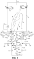
- end-port glass furnace (10) has side walls (11) and (12) and a feed station (20) where feed material (30) comprising solid glassmaking materials (known as batch and/or cullet) are charged into the furnace to be heated and melted.
- feed material (30) comprising solid glassmaking materials (known as batch and/or cullet) are charged into the furnace to be heated and melted.
- the flow of molten glass out of furnace (10) is represented as (90).
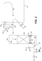
- the furnace (10) is equipped with first regenerator (100) on the furnace left side and second regenerator (200) on the furnace right side. Vertical cross-sectional views of the two regenerators are displayed in more detail in Figs. 2 and 3 . Pairs of regenerators (100) and (200) that are positioned as shown in Figs. 1a or 1b are connected to each other, and are operated, as described below with reference to Figs. 1-3 , 4-4a , 5-5a , 6-7, and 7a-7c .
- regenerator (200) is in the flue cycle wherein flue gas stream (50) from the interior of furnace (10) enters port neck (240) and then flows to the top space (530) of regenerator (200) past an oxygen analyzer (250).
- the flue gas stream heats checkers (represented as (520)) as it flows through passages between the checkers within regenerator (200), and enters chamber bottom space (500) through gas passages (515) supported on arch (510) which also supports the weight of the whole bed of checkers.
- checkers represented as (520)
- a portion (52) of the flue gases produced in furnace (10) may be by-passed to conduit (70) through a partially opened valve (350) then enters stack (340) to exhaust, by which is meant that it does not re-enter the furnace but instead is discharged to the atmosphere and/or conveyed to one or more other stations for storage and/or further treatment or any combination of such destinations.
- valve (350) is closed so that essentially all the furnace flue gas goes to regenerator (200) as flue gas stream (50).
- the cooled flue gas stream (201) exits the regenerator (200) in conduit (260), passes through an open valve (210) and oxygen sensor (310), and then enters the suction-side of blower (300).
- the majority of the flue gas (301) leaving the pressure-side of the blower passes through a damper (330) then a flow meter (332), and finally is directed into stack (340) through which this flue gas leaves the system to exhaust as defined herein.
- a portion (303) of the flue gas is recycled to the bottom of regenerator (100) by passing through conduit (320) and valve (360).
- the reforming fuel (RF) from stream (130) intersects and mixes with the RFG (303) at location (127) in conduit (128) which also communicates with the bottom space (400) of regenerator (100).
- This RFG/RF mixture enters the already pre-heated checker pack (420) of regenerator (100) through gas passages (415) on arch (410).
- Regenerator (100) has already been heated in a previous cycle by passage of flue gas from the furnace into and through the regenerator (100).
- the temperature of the RFG/RF mixture increases as it flows through the checker pack of regenerator (100).
- Some of the fuel may crack endothermically upon heating as it passes through the checker and form H2, other hydrocarbons and soot.
- the resulting mixed stream (143) of syngas and motive gas passes into furnace (10) and is combusted in furnace (10) to generate additional heat of combustion useful for heating and/or melting material in the furnace, such as glassmaking materials.
- Oxidant for combustion of the syngas is supplied by a conduit (135) with an opened valve (115). This oxidant can be air, or it can have an oxygen content higher than that of air, i.e.
- regenerator (200) is in the cycle of producing syngas.
- Fuel stream (942) is located to provide fuel to this location, when valve (944) is open, as described below.
- the heat recovery process proceeds with one regenerator in the flue cycle and one regenerator in the reforming cycle, as seen in Fig. 1 , for about 20 to 40 minutes or until the checkers in the reforming regenerator are too cold to provide sufficient heat to promote the desired endothermic chemical reactions.
- regenerator (200) was in the flue cycle and regenerator (100) was in the reforming cycle
- furnace (10) undergoes reversal in which regenerator (200) is transitioned to the reforming cycle for heat recovery and regenerator (100) is transitioned into the flue cycle for heat accumulation.
- regenerator (100) Before the reversal, remaining syngas in regenerator (100) is to be purged to furnace (10).
- reforming fuel supply to the regenerator is terminated by closing valve (120) while letting the flow of RFG from the other regenerator into the regenerator being purged continue, such as via blower (300).
- Valve (844) is opened so that fuel gas (842) (such as natural gas, methane, or any other combustible gaseous hydrocarbon product or composition) flows to the nozzle from which the motive gas was injected.
- fuel gas (842) such as natural gas, methane, or any other combustible gaseous hydrocarbon product or composition
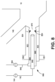
- fuel gas is flowed from (842) through nozzle (670) (which is seen in Figure 8 ) so that for a period typically of about 10 to 25 seconds fuel gas and oxidant motive gas are both flowing out of the nozzle (670).
- the flow of fuel gas does not necessarily impart motive force to the gas that is flowing at this point in time through the regenerator that is being purged.
- the flow of fuel gas is typically continued up to typically about 120 seconds after termination of the flow of reforming fuel was terminated.
- the fuel gas (842) is combusted at the nozzle, to provide heat to the charge that is in furnace (10).
- recycled flue gas continues to flow (typically at about double the previous flow rate) through the regenerator (100) to purge remaining syngas and residual fuel gas from this regenerator, into furnace (10).
- Remaining syngas in regenerator (100) is purged by the RFG for a specified amount of time so that nearly all the syngas in the regenerator is expelled to the furnace and combusted to completion.
- the combustion of fuel gas at the nozzle from which motive gas passes provides heat to the furnace even during the purging in which syngas is not being produced in the regenerator that is being purged.
- the combustion at the motive gas nozzle can be used to supplement and even to replace combustion of syngas from the regenerator, for instance at times when the TCR operation is shut down for maintenance or other reasons.
- regenerator After the regenerator has been sufficiently purged of syngas, the combustion of the fuel from (842) is stopped by closing valve (844), the flow of oxygen from the motive gas lance is stopped, stage oxidant flow is stopped, and valve positions are reversed so that RFG and fuel are fed to regenerator (200) to make syngas therein, and flue gas is flowed through regenerator (100) to heat it.
- the flows of fuel and oxidant gas are stopped for about 10 seconds to allow time for the affected valves to actuate and change positions.
- regenerator (100) Upon reversal following the purging, the flue gas from the furnace passes through regenerator (100), and a portion thereof passes to exhaust (as defined herein) while a portion or the balance is mixed with fuel and the mixture is passed through regenerator (200) and into the furnace.
- Valve (110) which had been closed is opened, valve (210) is closed, and valve (360) is closed and valve (380) is opened, to permit heated flue gas to pass from regenerator (100) toward and through blower (300), and to permit a portion (303) of this flue gas to pass into regenerator (200) after it is mixed with reforming fuel (230) which enters through valve (220) which had been closed but now is opened.
- Valve (115) which had been open is closed, as no combustion aided by oxidant through valve (115) occurs in this phase, and valve (225) is opened.
- the resulting mixture of reforming fuel and recycled flue gas undergoes in regenerator (200) the endothermic reactions which had occurred in regenerator (100) in the previous cycle as described herein, to produce syngas (425) which passes into furnace (10) where it is combusted with oxidant (235) that is fed through valve (225).
- valve (144) Upon the reversal, valve (144) is also closed and valve (244) is opened, so that motive gas stream (242) mixes with syngas emerging from regenerator (200) and the resulting mixture enters furnace (10) for combustion. Then, when production of syngas in regenerator (200) has proceeded sufficiently, the cycles are reversed again, but only after regenerator (200) is purged of syngas in the manner analogous to how regenerator (100) had been purged prior to the cycle that is now ending.
- furnace (10) may be co-fired with other burners such as (60) and (65) such that both syngas flame (40) and burner flames (62) and (64) co-exist.
- burners (60) and (65) may or may not be firing during the reversal process when the reforming regenerator (100) or (200) as the case may be is undergoing the purging sequence described above.
- the motive jet in the present invention employs two different general approaches to prevent the uncontrolled fuel flowing condition (i.e., uncontrolled flame shape) which has been recognized as being caused by the very low velocity of hot syngas entering the furnace through the TCR port.
- the first approach is to transform the low velocity syngas into a well-defined higher velocity gas stream using a motive gas within the syngas stream.
- the second approach is to place a sufficient number of high velocity jets around the syngas port to entrain syngas into multiple oxidant jets together with surrounding furnace gas to control both the flame shape and the flame temperature.
- the method can form a long oxy-fuel flame projecting from the firing wall toward the opposite wall of the furnace for the low velocity syngas fuel stream issuing from a firing port located in the firing wall.
- the motive gas stream in this invention can be employed (especially with oxy-fuel combustion) to produce a well-contoured flame with a low peak flame temperature in a furnace or other combustion chamber from a low velocity stream of fuel or oxygen of less than 15,2 m/s (50 ft/sec) and more preferably less than 7,6 m/s (25 ft/sec) wherein at least one high momentum motive gas stream (142) with a low mass flow rate is introduced into the low velocity stream in the gas supply passages (ducts) (alternately, (140) and (240)) connected to a furnace to form a higher velocity mixed stream in the direction of port exit (143) which is fed into the furnace.
- ducts gas supply passages
- ducts alternatively, (140) and (240)
- the velocity of the motive gas stream should be at least 30,5 m/s (100 ft/sec) and is preferably at least 121,9 m/s (400 ft/sec), more preferably at least 243,8 m/s (800 ft/sec).
- the mixed streams as they enter the furnace, after mixing, have gas velocities greater than 15,2 m/s (50 ft/sec) and more preferably greater than 30,5 m/s (100 ft/sec).
- This invention is particularly useful when either the fuel or the oxygen stream into which the motive gas stream is fed has a low gas density and a velocity in the passage of less than 9,1 m/s (30 ft/sec) or even less than 4,6 m/s (15 ft/sec).
- this invention it has been discovered that the risk of the flame (formed by combustion of the syngas or other fuel gas) lofting or rising toward the crown of the furnace is avoided, which avoids the risk of damage to the crown because of the very high flame temperature.
- the invention is particularly useful where the density of the fuel gas or syngas which is entrained into the motive gas as described herein, is lower than the density of the gaseous combustion products formed by the combustion in the furnace.
- the injection points of the mixed stream, and of any secondary streams such as oxidant, entering the furnace may be spaced apart to prevent rapid local mixing which could form a high temperature flame with high NOx emissions.
- the velocity of the mixed stream is defined as the average velocity of the motive gas stream and of the original low velocity stream into which the motive gas stream is fed.
- it is preferred that at least one of the streams entering the furnace has a velocity greater than 30,5 m/s (100 ft/sec), and preferably all streams have gas velocities greater than 30,5 m/s (100 ft/sec).
- the total mass flow rate of all motive gas streams is less than 60%, preferably less than 30%, and most preferably less than 20%, or even 15%, of the mass flow rate of the low velocity fuel stream into which the motive gas is fed.
- each motive gas stream is composed of fuel or oxidant that is combusted in the furnace.
- the motive gas most preferably comprises oxygen to be combusted in the furnace. It is especially preferable for the motive gas stream to comprise at least 75 vol.% oxygen and preferably at least 90 vol.% oxygen, especially in use with combustion of syngas from the thermo-chemical regenerator methods described herein.
- the mass flow rate of the motive gas injected into the fuel gas or syngas provides between 10% (or even 5%) to 35%, preferably between 10% to 25% (or even 10% to 20%), of the stoichiometric mass flow rate of oxygen required for complete combustion of the fuel gas or syngas into which the motive gas is injected.
- the motive gas stream is preferably comprised of a portion (that is, less than 100% of the stoichiometric requirement) of the oxidant used for combustion of the fuel that is in the stream into which the motive gas stream is fed. Any other gases such as compressed RFG, steam, fuel gas and air can be used as the motive gas.
- the motive gas stream comprising this portion of the combustion oxidant is supplied through a nozzle or multiple nozzles installed inside the fuel supply duct through which the low-velocity fuel stream passes from the regenerator to the furnace.
- This motive gas stream, comprising the portion of the combustion oxidant is at high velocity with very high momentum produced by use of suitable injection nozzles.
- the high momentum of the motive gas stream not only entrains, mixes, and combusts part of the surrounding low velocity fuel, but also entrains, propels and directs the remaining un-combusted low velocity fuel into the combustion enclosure (furnace) towards desired locations through momentum exchange between the fuel and the motive gas stream.
- At least 50 vol.%, preferably at least 70 vol.% and more preferably at least 90 vol.% of the fuel gas or syngas is entrained into the motive gas stream in the low velocity fuel gas duct before entering the furnace, forming the mixed stream that passes into the furnace.
- the ratio of the mass flow rate of fuel gas entrained to the mass flow rate of the motive gas injected is approximately proportional to the ratio of the recess distance L and the diameter D of the nozzle end through which the motive gas stream is fed into the duct, that is, L divided by D, wherein the recess distance L is defined as the distance between the injection point into the duct (at the end of nozzle (670)) to the duct exit to the furnace, i.e., to the inner surface of the furnace interior where the duct ends (L is the space shown as (690) in Fig. 5 ).
- the preferred range of L/D that provides a desired amount of syngas entrainment into the motive gas stream can be defined for any given apparatus by conducting tests with the specific geometries of the fuel supply duct and the motive gas nozzle, using the relationships described herein.
- a stream of secondary oxidant (also referred to herein as "2 nd oxidant”) can be introduced into the combustion enclosure from one or more injection points spaced apart from the duct that carries the mixed stream, for completing combustion of the remaining fuel which has been propelled into the furnace in the mixed stream.
- the secondary oxygen is injected from two to four injection points below the center line of the syngas duct. More preferably the secondary oxygen is injected from two to four injection points below the syngas duct so as to maintain an oxidizing atmosphere in at least the portion of the atmosphere within the lower part of the furnace that is in contact with material contained in the furnace.
- the momentums of the motive gas stream and of any secondary oxidant streams are much larger than the momentum of the stream into which the motive gas is fed. Therefore, flow field characteristics in the furnaces (such as flow directions, velocity magnitudes, and the location of the flow recirculation zones) are strongly influenced and mostly determined by the directions (i.e., vector angles) and the magnitude of the momentums designed for these two oxidant streams.
- This additional capability of being able to alter or modify furnace flow characteristics during the said combustion process is particularly advantageous for achieving optimized thermal performance and a desired temperature distribution in the furnace.
- Additional advantages include reduced NOx emissions, reduced particulate carry-over into the flue gas, and increased energy utilization efficiency in a glass furnace, and the ability to adjust the redox state (i.e. more oxidizing or less oxidizing, more reducing or less reducing) of the gaseous atmosphere near the molten glassmaking materials or other materials in the furnace.
- this aspect of the present invention permits establishing an oxidizing atmosphere over the charge in the furnace, which is often an aid in improving the properties of the product being produced.
- the location at which the motive gas stream is fed into the duct to mix with the low-velocity stream is recessed into the duct away from the hot interior walls of the furnace itself, so as to entrain most of the low velocity fuel stream and to limit or minimize entrainment of furnace flue gases into the duct.
- the combustion method of the present invention can also be implemented to influence the overall flow patterns in the furnace so that optimum furnace thermal performance is achieved. This is different from burners which use a high velocity jet to entrain a low velocity jet for combustion purposes only but not to significantly influence the overall furnace flow patterns.
- the motive gas stream and the 2 nd oxidant stream in the practice of this invention can be designed so that preferred furnace flow fields are obtained in order to avoid overheating of furnace refractory walls or crown, and to have low local gas velocities near the glass surfaces to minimize alkali volatilization. This method of controlling the overall furnace flow field is further described in more details below.
- both flue gas exhaust and pre-heated fuel gas supply share the same duct passage (i.e., regenerator port neck) alternately.
- the flue gas velocity at the port entrance is typically designed in the range of 6,1 m/s (20 ft/sec) up to 15,24 m/s (50 feet per second) or even up to 18,29 m/s (60 ft/sec) to prevent batch particle carry over and to facilitate a uniform flow distribution over a large cross-sectional area of the checker pack in the regenerator.
- the flue gas velocity is also restricted by the power of the exhaust blower, and by wear conditions resulting from high velocity at the internal surfaces of the refractory lined high temperature duct.
- the fuel gas has a resulting lower velocity through the shared duct.
- the present invention improves the discharge velocity of the lower velocity fuel gas stream into the combustion space, by imparting a higher momentum and higher velocity vector to the fuel gas stream in combination with the motive gas stream comprising oxidant. This is important for carrying out efficient combustion where the momentum of the fuel gas without the motive gas jet at the entrance to the combustion space is too low to maintain its own flow direction.
- the fuel gas will follow the natural circulation pattern of the existing convection cells within the combustion space, directing the fuel gas to contact wall and crown refractory surfaces in high concentration, prior to mixing with the oxidant for combustion.
- This condition is highly undesirable and can result in refractory damage, local overheating, unburned fuel escaping through the flue exit, and poor heat distribution to the process charge.
- the motive gas feature of the present invention solves all these undesirable conditions by imparting both momentum and direction to the fuel gas stream as it enters the combustion space, allowing the resulting mixture to be directed in a way that completes combustion within the available volume, and providing a favorable heat release pattern, low NOx and CO emissions, as well as controlled velocity at the glass surface to prevent excessive volatile generation from the melt surface.
- Low pressure fuels may be compressed to higher pressures in order to increase the momentum and velocity of the fuel jets for industrial applications.
- this method in general requires a great deal of safety measures and redundancies to attain safe operations, which increases the fuel compression costs quickly.
- Fuel compression is also limited by available engineering materials and is subjected to maximum fuel temperatures allowed.
- a high temperature and low pressure syngas fuel at a supply pressure of about 0,498 kPa (two inches of water column (i.e., 2"-H2O)) and its composition comprises CO, H2, CH4, and soot would be very costly to compress even at a moderate temperature of less than 260 °C (500 F).
- the pressure of the motive gas stream is utilized to direct and deliver low velocity fuels into a combustion enclosure with the use of nozzles to create high velocity streams of the motive gas, especially where the motive gas is oxidant.
- These nozzles can be made of high temperature refractory materials and, optionally, be mounted on the tips of water- or air-cooled metal lances for use. Since oxygen can be provided from commercially available sources such as VPSA apparatus or liquid oxygen supply at sufficiently high pressures to serve as the first and second oxidant streams, the present invention does not require costly fuel compression equipment and is easy, safe and very economical to apply.
- the current method and apparatus for low-velocity fuel combustion also has the added benefits of lowering NOx emissions and reducing peak flame temperatures, because the low velocity fuel is converted to a higher velocity mixed stream and combusted by at least two oxidants supplied to the combustion enclosure in a staged combustion manner, as described in U.S. Patent No. 6,394,790 and 5,601,425 .
- furnace overall flow patterns and flow characteristics can be altered or modified through distinct nozzle designs so that adequate amounts of flow momentum and stream flow angles are provided to the motive gas stream and the secondary oxidant stream.
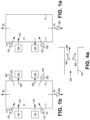
- regenerator (100) on the left side of wall (3) of the furnace and regenerator (200) on the right side of wall (3).
- regenerators (100) and (200) are each connected to ducts, also referred to herein as port necks (140) and (240) respectively, which connect to the interior of glass furnace (10).
- regenerator (100) is shown in the reforming cycle in which syngas (425) is produced by thermochemical reforming of fuel and recycled furnace flue gas in checker pack (420). This syngas stream (425) is usually comprised of CO, H2, CH4, CO2, N2, other hydrocarbon species and soot.
- Syngas stream (425) enters port neck (140) through a plane (630) and exits into the furnace for combustion through plane (640) which is the plane of the interior surface of wall (3).
- motive gas stream (142) passes through valve (144) to a metal lance (660) which has refractory nozzle (670).
- Lance (660) is described with reference to Fig. 8 , which includes motive gas stream (142), valve (144), fuel feed line (842), valve (844), port neck (140), and furnace (10), which are described in other drawing figures as well.
- Central passageway (848) and annular passageway (846) are provided, preferably concentric with each other.
- motive gas is fed through central passageway (848) and fuel is provided through annular passageway (846).
- annular passageway (846) is provided a jacket (853) of cooling air which enters through air inlet (851) and exits through air outlet (852). Openings (854) are provided in jacket (853) so that some of the cooling air can pass from jacket (853) to help keep nozzle (846A) at the end of passageway (846), and nozzle (848A), at the end of passageway (848), cooled and clean as when passage of fuel resumes the fuel will have a lesser tendency to crack and form soot which could foul the nozzle and deflect the axis of the flame whose base would be at the nozzle.
- the end (848A) of passageway (848) is preferably recessed by up to two refractory fuel port inside diameters from the end of nozzle (670), and the end of nozzle (670) is preferably recessed by up to two fuel port inside diameters from the opening into port neck (140).
- the motive gas stream (142) can be a portion of the combustion oxidant that is used to combust the syngas or other fuel gas which is being fed to the furnace.
- the refractory nozzle (670) is preferably designed to have a throughput of 10% of the total combustion oxidant flow and the oxidant injection velocity was choked at sonic velocity of about 299 m/s (980 ft/sec).
- the lance and the nozzle assembly are installed inside port neck (duct) (140) with the discharge end of nozzle (670) recessed a distance (690) from the plane (640) which is defined above.
- the nozzle (670) can comprise numerous holes (not shown) in its discharge end which when are preferably designed so that oxidant flows through the holes in direction(s) to avoid overheating of refractories inside port neck (140).
- the motive gas stream (142) passes out of nozzle (670) as a high velocity stream that entrains much of the low velocity syngas (425) thereby forming a mixed fuel stream (600) in the port neck (duct) (140).
- the mixed stream (600) passes from inside duct (140) out into furnace (10).
- the mixed fuel stream has a sufficient momentum to resist lofting upwards toward the top (crown) of furnace (10) and to instead penetrate into the interior of furnace (10) in a preferred direction (630) aided by the design of the refractory nozzle (670) to minimize or avoid the flame touching or impinging on the interior walls and crown of the furnace.
- Figure 4a illustrates an embodiment in which there are two nozzles (660) which are positioned at a diverging angle with respect to each other. Streams of motive gas pass out of both nozzles (660) inside the duct (140) to mix with stream (425) inside duct (140) and the resulting mixed stream (600) passes from the duct into the interior of furnace (10).
- regenerators (100) and (200) have lances (660) to be used to inject motive gas when the regenerator is operated in the reforming cycle, motive gas is fed from only the lance (660) that is associated with the regenerator which is operating in the reforming cycle.
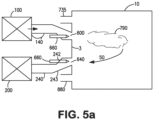
- One or more secondary oxidant streams (750) can be supplied to the furnace interior, each through its own lance (760) and nozzle (770) assembly inside a refractory block (735) for the injection of the balance of the combustion oxidant for complete combustion of the syngas or fuel gas.
- Low velocity syngas (620) that was not entrained into the motive gas stream (142) can be entrained into the secondary oxidant stream (785) that passes into the furnace for combustion.
- Injection holes in nozzle(s) (770) are designed so that the secondary oxidant entrains surrounding furnace gases before mixing with the unburned syngas or fuel gas stream propelled by the motive gas stream (142) so that a desired main flame (790) is formed for heating a charge in the furnace, such as for glass melting.
- the main flame (790) provides radiative and convective heat energy to the charge (800 and 810) in the furnace which may include solids (800) (such as batch and/or cullet materials for glassmaking) and molten liquid (810).
- Flue gas (50) from the furnace interior is directed to regenerator (200) to preheat checkers therein as described above.
- Figure 6 is a view looking at a portion of wall (3) from inside the furnace. As seen in Figure 6 , nozzles (770) are located below the horizontal center line of the outlet (140A) of duct (140), and are preferably below the duct outlet (140A). While two nozzles (770) are depicted, there are preferably two to four such nozzles (770) at each outlet (140A).
- FIG. 2 In actual preferred practice as represented in Fig. 2 , additional injectors for fuel gas or syngas, for a motive gas stream and for secondary oxidant streams, functionally equivalent to those described above, would also be installed in port neck (duct) (240) and refractory block(s) (835) on the furnace right side, though not shown in Figures 4 and 5 . Fuel (942) is also shown in Fig. 2 . These injection devices would be used when the TCR process has undergone a reversal to a cycle in which syngas is produced in regenerator (200) and the furnace flue gas is directed to regenerator (100) to preheat checker pack (420).
- Yet another advantage of the present invention is that the use of the motive gases allows proper distribution of low velocity reactants into a furnace under which the ducts connecting to the furnace and regenerators are not straight but angled in vertical or horizontal directions with respect to the direction of a regenerator.
- port neck (140) is shown to have a sharp angle with respect to the upward direction of regenerator (100).
- the height of the regenerator crown (432) is about 2,29 m (7.5 ft) higher than the glass surface (811) in furnace (10). This unusually large difference in height is because the regenerator was installed on the existing basement levels without excavation.
- the high momentum motive gas issues from lance (660) also provides a "pumping" effect to draw the low velocity, low density, and highly buoyant syngas (425) from the higher elevation regenerator top space toward the lower elevation furnace combustion space.
- This pumping effect beneficially reduces the pressure requirement that the blower (300, Fig 1 ) has to develop on the pressure side, thus reduces process operating costs.
- port neck (240) is also sharply angled like port neck (140), flame (790) and hot walls in furnace (10) have no direct views on the colder regenerator top space (530, Fig 2 ) of the regenerator (200) that is in the flue cycle.
- This obstructed view from the hot furnace to the colder regenerator top space reduces direct radiation heat transfer from the furnace (10) to the regenerator (200), which reduces port radiation losses to the furnace ambient and increases the TCR heat recovery efficiency.
- the present invention can also be applied to for example glass furnaces where port necks are angled in horizontal directions and connected to the regenerators.
- This application of motive lances may occur when the top course of the checker pack (420) is almost at the same elevation of the glass surface (811), thus the elevation of the regenerator crown is approximately at the same level as the furnace crown.
- Figure 5a illustrates such a TCR heat recovery arrangement viewed from above where port necks (140, 240) are angled in the horizontal directions and motive lance (660) is installed in port neck (140) of the reforming regenerator (100).
- Each oxidant stream should have an oxygen concentration greater than 50% by volume, preferably greater than 75% by volume.
- Each motive gas stream as fed into the duct to mix with a fuel stream or other stream should have a velocity of 61,0 m/s (200 ft/sec) up to sonic velocity or even supersonic velocity at the nozzle exit.
- the pressure of the combustion enclosure is 101 kPa (1 atm)
- the sonic velocity for O2 (21 °C (70F) inlet) at a nozzle exit is 299 m/s (980 ft/sec); for 21 °C (70F) air, sonic velocity at a nozzle exit is 314 m/s (1030 ft/sec))
- a motive gas that is fed into a given fuel stream should preferably comprise (by volume) 1% to 50% (more preferably 5% to 30%, and even more preferably 5% to 15%) of the total combustion oxygen that is fed into the furnace for combustion of the fuel in that fuel stream.
- At least 50 vol.%, preferably 70 vol.% and more preferably at least 90 vol.% of the fuel gas or syngas is entrained into the motive gas stream in the fuel duct, forming the mixed stream that passes into the furnace.
- the ratio of the mass flow rate of the syngas or other fuel gas that is entrained, to the mass flow rate of the motive gas injected is approximately proportional to the ratio of L and D, that is, the recess distance L divided by the diameter D of the motive gas nozzle, wherein the recess distance L is defined as the distance (690) along the axis of the lance (660) between the injection point in the duct to the duct exit plane to the furnace, i.e., to the interior surface of the furnace interior where the duct ends.
- the preferred range of the L/D ratio for the duct depends on the number of streams of motive gas fed into the duct, N, and the ratio R of the total mass flow rate of syngas passing through the duct to the total mass flow rate of motive gas stream being fed into the duct.
- N the number of streams of motive gas fed into the duct
- R the ratio of the total mass flow rate of syngas passing through the duct to the total mass flow rate of motive gas stream being fed into the duct.
- L can be provided by positioning of each nozzle (670) within the duct
- D can be provided by providing a nozzle (670) with the desired diameter
- an appropriate number N of lances (660) and nozzles (670) can be provided in the duct wherein each lance (660) is fed motive gas as described herein
- the value of R can be provided by implementing appropriate total mass flow rates of the syngas and of the motive gas.
- the motive gas that is fed into a given duct is fed through one or more lances (660) (i.e. a total of N lances) positioned in the duct.
- the preferred number of motive gas streams in a duct, N is determined by the size and shape of the cross-sectional area of the duct and the desired flame shape in the furnace.
- the cross-sectional area of the duct is large two to four, or even six or more, motive gas streams, each fed through its own lance (660), may be appropriate to achieve 50 to 90% (preferably 70 to 90%) entrainment of syngas into the motive gas within the duct space available.
- the direction of each motive gas stream can be adjusted to form different flame shapes in combination with the direction and number of secondary oxidant streams.
- Fig. 6 illustrates an embodiment in which there is one nozzle (670) corresponding to one lance (660) for the duct, that is, N equals one.
- N the expression (L/D) x (N/R) is determined with N being the total number of nozzles feeding motive gas into the duct and with R being determined on the basis of the total mass flow rate of syngas passing through the duct and the total mass flow rate of motive gas being fed through all N of the nozzles.
- Suitable dimensions L and D and suitable mass flow rates for the syngas and the motive gas that may be employed in practice will depend on factors including the overall size and firing rate per port of the furnace with which the invention is employed.
- representative non-limiting values of L can be 25,4 to 203,2 cm (10 to 80 inches); of D, 0,64 2,54 cm (1 ⁇ 4-inch to 1 inch); of syngas mass flow rate, 453,6 to 1814,4 kg/h (1000 to 4000 pounds per hour (lbs/hr)); and with the motive gas mass flow rate selected as described herein with reference to values including the mass flow rate ratios, oxygen contents, and velocities described herein.
- the present invention can also be practiced in embodiments in which the motive gas does not have to contain oxygen.
- the motive gas can be any gas, including steam, compressed air, natural gas, carbon dioxide, compressed recycled flue gas, or any other gaseous composition that is compatible with the furnace.
- Multiple motive gas streams may be used to regulate the shape of a flame in the furnace so that the flame is wide and also has suitable length and directions for applications use.
- the need for wider flames is especially critical in a so-called cross-fired furnace when the furnace length in the longitudinal direction is large.
- a so-called cross-fired furnace when the furnace length in the longitudinal direction is large.
- five to seven pairs of regenerator ports are placed on the side walls of the furnace. Each flame projects cross-wise from one side wall to the opposite side wall and the multiple flames provide good flame coverage over a large surface area of the furnace where melting of the batch/cullet and fining of glassmelt occur continuously.
- each orifice may or may not be the same.
- These motive lances can be located and staggered in a vertical or horizontal direction or any appropriate locations of a duct cross-section area where the low velocity fuel or oxidant flows through then enters the furnace. It is expected that the arrangement of these lances which house multiple motive gas streams for creating a wide flame may depend on the shape and the cross-section area of the duct. It is also important to note that the number of these motive lances applicable in a duct may be limited by the available duct cross-section area.
- each motive lance (660) may need sufficient separation distance from the other lances in the same duct so that the mixed streams (600) from each nozzle orifices are not interfering with each other for the ongoing development of a wide flame at the duct exit (640) and in the furnace (10).
- the values for the momentum of the oxidant, motive gas, and fuel (syngas) streams fed into a furnace, and for the momentum of the gaseous combustion products (flue gas) that exits the furnace depend on the firing rate of the furnace.
- the typical firing rates can be on the order of 2,28 to 63,31 million kJ (5 million to 60 million BTU) per hour per firing port (i.e. the ports at which combustion occurs in the furnace).
- typical values for the respective momentums are on the order of 16590 to 207385 kg/h*m/s (120,000 to 1,500,000 pounds/hour times feet per second (lb/hr* ft/sec)) for the momentum of the oxidant (referred to herein as "O"); on the order of 12443 to 152083 kg/h*m/s (90,000 to 1,100,000 (lb/hr*ft/sec)) for the momentum of the motive gas (referred to herein as "M”); on the order of 1382 to 16590 kg/h*m/s (10,000 to 120,000 (lb/hr*ft/sec)) for the momentum of the fuel gas (referred to herein as "F”); and on the order of 8295 to 96780 kg/h*m/s (60,000 to 700,000 (lb/hr*ft/sec)) for the momentum of the gaseous combustion products (referred to herein as "X").
- the oxygen jets are placed close to the nearest side wall and injected toward the front wall, parallel to the side walls, the oxygen jets would bend toward the side wall due to the Coanda effect, resulting in fuel rich flame touching the side wall. This condition can be avoided by angling the oxygen jets away from the side wall.
- the optimum angle of oxygen jets depends on the furnace configuration and the placement of oxygen jets.
- the momentum of each oxidant stream is preferably larger than that of the fuel stream. Therefore, flow field characteristics in the furnaces, such as flow directions, velocity magnitudes, and the location of the flow recirculation zones, are strongly influenced and mostly determined by the directions (i.e., vector angles) and the magnitude of the momentums designed for each oxidant stream.
- the capability to modify furnace flow characteristics by varying the flow condition of each oxidant stream is particularly advantageous for creating a desired flame shape, achieving optimized thermal performance and a desired temperature distribution in the furnace. Furthermore it helps to design a flame to minimize NOx emissions and particulate carry-over, and to achieve the highest fuel energy utilization efficiency in a glass furnace.
- the overall flow pattern in the furnace was found to be different from that of an air fired regenerative furnace.
- the conventional air flame design was applied to the TCR flame design, some of the low velocity reformed fuel coming out of the firing port was short-circuited to the exhaust port and created an undesirable heating pattern in the furnace.
- the present inventors found that the key flow parameters preventing short-circuiting of either fuel or oxygen flow to the exhaust port is to make the total momentum of oxygen and fuel flows injected into the furnace is at least 100%, preferably 150% of the momentum of flue gas flow exiting the exhaust port. Furthermore if either fuel of oxygen flow has less than 30% of the momentum of the flue gas exiting the exhaust port, the weaker flow must be quickly entrained into the stronger flow near the injection port and projected toward the front wall.
- the present invention can also be practiced in embodiments in which the second oxidant may not provide the balance of the oxygen required to completely combust the fuel entering the furnace. It can be advantageous to provide the amount of oxygen required to completely combust the fuel (after the mixed stream including the motive gas has propelled the fuel into the furnace) from two or more oxidant streams that have significantly different injection locations. For example, a second oxidant stream is injected in close proximity to the location where the mixed fuel stream enters the furnace, while a third oxidant stream is fed after the second oxidant stream has been substantially consumed in the flame. A typical location for this third oxidant stream is closer to the opening where the flue gas exits the furnace.
- the advantage of this arrangement of oxidant streams is the reduction of NOx formation by the combustion process. This method of staging the combustion process to reduce NOx emissions is well known, but the combination with the combustion process for a very low momentum fuel stream is new.
Landscapes
- Engineering & Computer Science (AREA)
- Chemical & Material Sciences (AREA)
- Mechanical Engineering (AREA)
- General Engineering & Computer Science (AREA)
- Combustion & Propulsion (AREA)
- Materials Engineering (AREA)
- Organic Chemistry (AREA)
- Environmental & Geological Engineering (AREA)
- Hydrogen, Water And Hydrids (AREA)
Claims (16)
- Verfahren zum Ausführen einer Verbrennung in einem Ofen (10), umfassend(A) Verbrennen von Brennstoff in einem Ofen, um gasförmige Verbrennungsprodukte herzustellen; und(B) Ausführen der folgenden Abfolge von Schritten (1) bis einschließlich (4):(1)(i) Leiten eines Anteils der gasförmigen Verbrennungsprodukte in und durch einen gekühlten ersten Regenerator, um den ersten Regenerator zu erhitzen und den Anteil der gasförmigen Verbrennungsprodukte abzukühlen,(ii) Leiten von mindestens einem Teil des gekühlten Anteils der gasförmigen Verbrennungsprodukte aus dem ersten Regenerator und des gasförmigen Brennstoffs in einen beheizten zweiten Regenerator und, in dem zweiten Regenerator, Reagieren der gasförmigen Verbrennungsprodukte und des gasförmigen Brennstoffs in einer endothermen Reaktion in dem zweiten Regenerator, um Synthesegas auszubilden, umfassend Wasserstoff und CO,(iii) Leiten des Synthesegases, das in dem zweiten Regenerator ausgebildet wird, mit einer Geschwindigkeit von weniger als 15,24 m/s (50 Fuß pro Sekunde) in einen ersten Kanal, der einen Auslass aufweist, der mit dem Inneren des Ofens verbunden ist,(iv) Einspritzen von mindestens einem Treibgasstrom, der eine Geschwindigkeit von mindestens 30,48 m/s (100 Fuß pro Sekunde) aufweist, aus einer ersten Düse in dem ersten Kanal in das Synthesegas in dem ersten Kanal stromaufwärts von dem Inneren des Ofens, wobei dadurch das Synthesegas in den Treibgasstrom in dem ersten Kanal mitgerissen wird und in dem ersten Kanal ein Mischstrom ausgebildet wird, umfassend eine Mischung aus dem Synthesegas und dem Treibgas und der eine Geschwindigkeit von mehr als 15,24 m/s (50 Fuß pro Sekunde) aufweist, und(v) Leiten des Mischstroms mit einer Geschwindigkeit von mehr als 15,24 m/s (50 Fuß pro Sekunde) aus dem ersten Kanal in den Ofen und Verbrennen des Mischstroms mit einem oder mehreren Oxidationsmittelströmen, die in den Ofen eingespritzt werden; und dann(2)(i) Unterbrechen der Leitung von gasförmigem Brennstoff in den zweiten Regenerator, Fortsetzen des Leitens gekühlter gasförmiger Verbrennungsprodukte in und durch den zweiten Regenerator, wobei dadurch Brennstoff und Synthesegas aus dem zweiten Regenerator entfernt werden und die Konzentration von Brennstoff und Synthesegas in dem zweiten Regenerator gesenkt wird, Zuführen von Brennstoff und gasförmigem Oxidationsmittel aus der ersten Düse in dem ersten Kanal und Verbrennen dieser, um Verbrennungshitze zu erzeugen, die das Innere des Ofens erhitzt, und anschließend Unterbrechen der Einspritzung des gasförmigen Oxidationsmittels aus der ersten Düse in dem ersten Kanal, so dass nur Brennstoff aus der ersten Düse herausgeleitet wird, und Verbrennen des Brennstoffs mit einem oder mehreren Oxidationsmittelströmen, die in den Ofen eingespritzt werden; und anschließend(ii) Unterbrechen des Brennstoffstroms aus der ersten Düse in den ersten Kanal und Unterbrechen der Verbrennung von Brennstoff aus der ersten Düse und Unterbrechen der Leitung von gasförmigen Verbrennungsprodukten aus dem Ofen durch den ersten Regenerator; und dann(3)(i) Leiten eines Anteils der gasförmigen Verbrennungsprodukte in und durch einen gekühlten zweiten Regenerator, um den zweiten Regenerator zu erhitzen und den Anteil der gasförmigen Verbrennungsprodukte abzukühlen,(ii) Leiten von mindestens einem Teil des gekühlten Anteils der gasförmigen Verbrennungsprodukte aus dem zweiten Regenerator und des gasförmigen Brennstoffs in einen ersten zweiten Regenerator und, in dem ersten Regenerator, Reagieren der gasförmigen Verbrennungsprodukte und des gasförmigen Brennstoffs in einer endothermen Reaktion in dem ersten Regenerator, um Synthesegas auszubilden, umfassend Wasserstoff und CO,(iii) Leiten des Synthesegases, das in dem ersten Regenerator ausgebildet wird, mit einer Geschwindigkeit von weniger als 15,24 m/s (50 Fuß pro Sekunde) in einen zweiten Kanal, der einen Auslass aufweist, der mit dem Inneren des Ofens verbunden ist,(iv) Einspritzen von mindestens einem Treibgasstrom, der eine Geschwindigkeit von mindestens 30,48 m/s (100 Fuß pro Sekunde) aufweist, aus einer zweiten Düse in dem zweiten Kanal in das Synthesegas in dem zweiten Kanal stromaufwärts von dem Inneren des Ofens, wobei dadurch das Synthesegas in den Treibgasstrom in dem zweiten Kanal mitgerissen wird und in dem zweiten Kanal ein Mischstrom ausgebildet wird, umfassend eine Mischung aus dem Synthesegas und dem Treibgas und der eine Geschwindigkeit von mehr als 15,24 m/s (50 Fuß pro Sekunde) aufweist, und(v) Leiten des Mischstroms mit einer Geschwindigkeit von mehr als 15,24 m/s (50 Fuß pro Sekunde) aus dem zweiten Kanal in den Ofen und Verbrennen des Mischstroms mit einem oder mehreren Oxidationsmittelströmen, die in den Ofen eingespritzt werden; und dann(4)(i) Unterbrechen der Leitung von gasförmigem Brennstoff in den ersten Regenerator, Fortsetzen des Leitens von gekühlten gasförmigen Verbrennungsprodukten in und durch den ersten Regenerator, wobei dadurch Brennstoff und Synthesegas aus dem ersten Regenerator entfernt werden und die Konzentration von Brennstoff und Synthesegas in dem ersten Regenerator gesenkt wird, Zuführen von Brennstoff und gasförmigem Oxidationsmittel aus der zweiten Düse in dem zweiten Kanal und Verbrennen dieser, um Verbrennungshitze zu erzeugen, die das Innere des Ofens erhitzt, und anschließend Unterbrechen der Einspritzung des gasförmigen Oxidationsmittels aus der zweiten Düse in dem zweiten Kanal, so dass nur Brennstoff aus der zweiten Düse heraus geleitet wird, und Verbrennen des Brennstoffs mit dem einen oder den mehreren Oxidationsmittelströmen, die in den Ofen eingespritzt werden; und anschließend(ii) Unterbrechen des Brennstoffstroms aus der zweiten Düse in den zweiten Kanal und Unterbrechen der Verbrennung von Brennstoff aus der zweiten Düse und Unterbrechen der Leitung von gasförmigen Verbrennungsprodukten aus dem Ofen durch den zweiten Regenerator; und dann(C) Wiederholen von Schritt (B) mindestens einmal.
- Verfahren nach Anspruch 1, wobei jede Treibstrahldüse einen Innendurchmesser D aufweist und sich in einem Abstand L stromaufwärts von der Innenwand des Ofens befindet, und der Wert von (L/D) x (N/R) von 4 bis 25 liegt, wobei N die Anzahl der Treibgasströme ist, die in das Synthesegas in dem Kanal eingespritzt werden, und R das Verhältnis der gesamten Massenströmungsrate des Synthesegases, das in den Kanal geleitet wird, zu der gesamten Massenströmungsrate des Stroms oder aller Ströme des Treibgases ist, die in den Kanal eingespritzt werden.
- Verfahren nach Anspruch 1, wobei das Treibgas Sauerstoff oder Luft umfasst.
- Verfahren nach Anspruch 1, wobei das Treibgas einen Sauerstoffgehalt von mindestens 75 Vol.-% Sauerstoff aufweist.
- Verfahren nach Anspruch 1, wobei der Sauerstoffgehalt der Mischung aus Treibgas und Synthesegas weniger als der stöchiometrische Bedarf für eine vollständige Verbrennung des Synthesegases in der Mischung ist, und wobei ein oder mehrere sekundäre Ströme des gasförmigen Oxidationsmittels, umfassend Sauerstoff, in den Ofen eingespritzt werden, um mit dem restlichen Synthesegas in der Mischung zu verbrennen.
- Verfahren nach Anspruch 5, wobei der eine oder die mehreren sekundären Ströme des gasförmigen Oxidationsmittels von unterhalb der Mittellinie des Auslasses oder von unterhalb des Auslasses aus dem ersten oder dem zweiten Kanal in den Ofen eingespritzt werden.
- Verfahren nach Anspruch 1, wobei der Brennstoff und das Synthesegas in dem Ofen mit dem Oxidationsmittel verbrannt werden, umfassend mindestens 75 Vol.-% Sauerstoff.
- Verfahren nach Anspruch 1, wobei das Synthesegas, das in den ersten Kanal geleitet wird, und das Synthesegas, das in den zweiten Kanal geleitet wird, mit einer Geschwindigkeit von weniger als 15,24 m/s (50 Fuß pro Sekunde) geleitet werden.
- Verfahren nach Anspruch 1, wobei der mindestens eine Strom von Treibgas, der in das Synthesegas in dem ersten Kanal eingespritzt wird, eine Geschwindigkeit von mindestens 121,92 m/s (400 Fuß pro Sekunde) aufweist und der mindestens eine Strom von Treibgas, der in das Synthesegas in dem zweiten Kanal eingespritzt wird, eine Geschwindigkeit von mindestens 121,92 m/s (400 Fuß pro Sekunde) aufweist.
- Verfahren nach Anspruch 1, wobei die Massenströmungsrate des Treibgases, das in das Synthesegas in dem ersten Kanal und in das Synthesegas in dem zweiten Kanal eingespritzt wird, weniger als 30 %, optional weniger als 15 % der Massenströmungsrate des Synthesegases beträgt, in das das Treibgas eingespritzt wird.
- Verfahren nach Anspruch 1, wobei das Treibgas, das in den ersten Kanal und in den zweiten Kanal eingespritzt wird, Sauerstoff umfasst und die Massenströmungsrate des Treibgases, das in das Synthesegas in jedem Kanal eingespritzt wird, zwischen 5 % und 35 % der stöchiometrischen Massenströmungsrate von Sauerstoff beträgt, der für die vollständige Verbrennung des Synthesegases erforderlich ist, in das das Treibgas eingespritzt wird.
- Verfahren nach Anspruch 1, wobei der Mischstrom, der aus dem ersten Kanal in den Ofen geleitet wird, und der Mischstrom, der aus dem zweiten Kanal in den Ofen geleitet wird, mit einer Geschwindigkeit von mehr als 30,48 m/s (100 Fuß pro Sekunde) geleitet werden.
- Verfahren nach Anspruch 1, wobei mindestens 70 Vol.-% des Synthesegases in den Treibgasstrom in den ersten und zweiten Leitungen mitgerissen werden, um dadurch in den Leitungen mindestens einen Mischstrom auszubilden.
- Verfahren nach Anspruch 1, wobei die Dichte des Synthesegases, das in dem Treibgas mitgerissen wird, geringer als die Dichte der gasförmigen Produkte ist, die durch die Verbrennung des Mischstroms entstehen.
- Verfahren nach Anspruch 1, wobei der Ofen eine Ladung enthält, die durch Verbrennung des Brennstoffgases in dem Ofen erhitzt werden soll, wobei durch die Verbrennung eine oxidierende Atmosphäre über der Ladung in dem Ofen erzeugt wird.
- Verfahren nach Anspruch 1, wobei bei der Verbrennung des Mischstroms mit einem oder mehreren Oxidationsmittelströmen, die in den Ofen eingespritzt werden, eine Flamme ausbildet, die die Innenwände oder die Decke des Ofens sichtbar nicht berührt.
Applications Claiming Priority (2)
| Application Number | Priority Date | Filing Date | Title |
|---|---|---|---|
| US201962850079P | 2019-05-20 | 2019-05-20 | |
| PCT/US2020/028177 WO2020236348A1 (en) | 2019-05-20 | 2020-04-15 | Method of carrying out combustion in a furnace with thermochemical regeneration |
Publications (3)
| Publication Number | Publication Date |
|---|---|
| EP3972939A1 EP3972939A1 (de) | 2022-03-30 |
| EP3972939C0 EP3972939C0 (de) | 2025-01-08 |
| EP3972939B1 true EP3972939B1 (de) | 2025-01-08 |
Family
ID=70482909
Family Applications (1)
| Application Number | Title | Priority Date | Filing Date |
|---|---|---|---|
| EP20723737.1A Active EP3972939B1 (de) | 2019-05-20 | 2020-04-15 | Verfahren zur durchführung einer verbrennung in einem ofen mit thermochemischer regeneration |
Country Status (10)
| Country | Link |
|---|---|
| US (1) | US12203705B2 (de) |
| EP (1) | EP3972939B1 (de) |
| CN (1) | CN113841021B (de) |
| AU (1) | AU2020279576B2 (de) |
| CA (1) | CA3139133A1 (de) |
| ES (1) | ES3010723T3 (de) |
| MX (1) | MX2021013199A (de) |
| MY (1) | MY196207A (de) |
| PL (1) | PL3972939T3 (de) |
| WO (1) | WO2020236348A1 (de) |
Families Citing this family (4)
| Publication number | Priority date | Publication date | Assignee | Title |
|---|---|---|---|---|
| US12460814B2 (en) * | 2021-12-31 | 2025-11-04 | Honeywell International Inc. | Low NOx gas burner with cooled flue gas recycle |
| CN115611237A (zh) * | 2022-11-03 | 2023-01-17 | 玻璃新材料创新中心(安徽)有限公司 | 一种全氧燃烧玻璃窑炉热化学再生燃烧方法 |
| JPWO2024111440A1 (de) * | 2022-11-25 | 2024-05-30 | ||
| WO2024111441A1 (ja) * | 2022-11-25 | 2024-05-30 | Agc株式会社 | ガラス製造方法、及びガラス製造装置 |
Family Cites Families (9)
| Publication number | Priority date | Publication date | Assignee | Title |
|---|---|---|---|---|
| US4761132A (en) * | 1987-03-04 | 1988-08-02 | Combustion Tec, Inc. | Oxygen enriched combustion |
| BR9404470A (pt) | 1993-11-17 | 1997-03-11 | Praxair Technology Inc | Processo para conduçao de combustao com simultânea geraçao reduzida de oxidos de nitrogênio |
| US5601425A (en) | 1994-06-13 | 1997-02-11 | Praxair Technology, Inc. | Staged combustion for reducing nitrogen oxides |
| US6113874A (en) | 1998-04-29 | 2000-09-05 | Praxair Technology, Inc. | Thermochemical regenerative heat recovery process |
| US10184659B2 (en) * | 2015-04-15 | 2019-01-22 | Praxair Technology, Inc. | Low-NOx combustion method |
| PT3283823T (pt) * | 2015-04-16 | 2019-11-29 | Praxair Technology Inc | Métodos de combustão para corrente de combustível de baixa velocidade |
| US10458712B2 (en) * | 2015-08-28 | 2019-10-29 | Praxair Technology, Inc. | Thermochemical regeneration with oxidant preheating |
| US10059615B2 (en) * | 2015-10-29 | 2018-08-28 | Praxair Technology, Inc. | Thermochemical regeneration and heat recovery in glass furnaces |
| MX2018007098A (es) * | 2015-12-23 | 2018-09-07 | Praxair Technology Inc | Horno de vidrio con índice de producción mejorado. |
-
2020
- 2020-04-15 AU AU2020279576A patent/AU2020279576B2/en active Active
- 2020-04-15 ES ES20723737T patent/ES3010723T3/es active Active
- 2020-04-15 MX MX2021013199A patent/MX2021013199A/es unknown
- 2020-04-15 US US17/435,611 patent/US12203705B2/en active Active
- 2020-04-15 EP EP20723737.1A patent/EP3972939B1/de active Active
- 2020-04-15 WO PCT/US2020/028177 patent/WO2020236348A1/en not_active Ceased
- 2020-04-15 CA CA3139133A patent/CA3139133A1/en active Pending
- 2020-04-15 PL PL20723737.1T patent/PL3972939T3/pl unknown
- 2020-04-15 MY MYPI2021006420A patent/MY196207A/en unknown
- 2020-04-15 CN CN202080036452.9A patent/CN113841021B/zh active Active
Also Published As
| Publication number | Publication date |
|---|---|
| US12203705B2 (en) | 2025-01-21 |
| EP3972939A1 (de) | 2022-03-30 |
| EP3972939C0 (de) | 2025-01-08 |
| BR112021020949A2 (pt) | 2021-12-14 |
| CN113841021A (zh) | 2021-12-24 |
| MX2021013199A (es) | 2021-12-10 |
| US20220146202A1 (en) | 2022-05-12 |
| AU2020279576B2 (en) | 2023-11-30 |
| PL3972939T3 (pl) | 2025-03-10 |
| ES3010723T3 (en) | 2025-04-04 |
| CA3139133A1 (en) | 2020-11-26 |
| WO2020236348A1 (en) | 2020-11-26 |
| AU2020279576A1 (en) | 2021-12-16 |
| CN113841021B (zh) | 2023-07-28 |
| MY196207A (en) | 2023-03-23 |
Similar Documents
| Publication | Publication Date | Title |
|---|---|---|
| EP3283823B1 (de) | Verfahren zur verbrennung mit brennstoffstrom mit niedriger geschwindigkeit | |
| EP3972939B1 (de) | Verfahren zur durchführung einer verbrennung in einem ofen mit thermochemischer regeneration | |
| KR20060051175A (ko) | 산화제 분사 방법 | |
| US10112860B1 (en) | Thermochemical regeneration with fuel additions | |
| EP3984967B1 (de) | Verfahren zur rückführung von rauchgas zur thermochemischen regeneration | |
| BR112021020949B1 (pt) | Método de realização de combustão em um forno |
Legal Events
| Date | Code | Title | Description |
|---|---|---|---|
| STAA | Information on the status of an ep patent application or granted ep patent |
Free format text: STATUS: UNKNOWN |
|
| STAA | Information on the status of an ep patent application or granted ep patent |
Free format text: STATUS: THE INTERNATIONAL PUBLICATION HAS BEEN MADE |
|
| PUAI | Public reference made under article 153(3) epc to a published international application that has entered the european phase |
Free format text: ORIGINAL CODE: 0009012 |
|
| STAA | Information on the status of an ep patent application or granted ep patent |
Free format text: STATUS: REQUEST FOR EXAMINATION WAS MADE |
|
| 17P | Request for examination filed |
Effective date: 20211119 |
|
| AK | Designated contracting states |
Kind code of ref document: A1 Designated state(s): AL AT BE BG CH CY CZ DE DK EE ES FI FR GB GR HR HU IE IS IT LI LT LU LV MC MK MT NL NO PL PT RO RS SE SI SK SM TR |
|
| DAV | Request for validation of the european patent (deleted) | ||
| DAX | Request for extension of the european patent (deleted) | ||
| STAA | Information on the status of an ep patent application or granted ep patent |
Free format text: STATUS: EXAMINATION IS IN PROGRESS |
|
| 17Q | First examination report despatched |
Effective date: 20221212 |
|
| GRAP | Despatch of communication of intention to grant a patent |
Free format text: ORIGINAL CODE: EPIDOSNIGR1 |
|
| STAA | Information on the status of an ep patent application or granted ep patent |
Free format text: STATUS: GRANT OF PATENT IS INTENDED |
|
| INTG | Intention to grant announced |
Effective date: 20240508 |
|
| GRAJ | Information related to disapproval of communication of intention to grant by the applicant or resumption of examination proceedings by the epo deleted |
Free format text: ORIGINAL CODE: EPIDOSDIGR1 |
|
| STAA | Information on the status of an ep patent application or granted ep patent |
Free format text: STATUS: EXAMINATION IS IN PROGRESS |
|
| GRAP | Despatch of communication of intention to grant a patent |
Free format text: ORIGINAL CODE: EPIDOSNIGR1 |
|
| STAA | Information on the status of an ep patent application or granted ep patent |
Free format text: STATUS: GRANT OF PATENT IS INTENDED |
|
| INTC | Intention to grant announced (deleted) | ||
| INTG | Intention to grant announced |
Effective date: 20240809 |
|
| GRAS | Grant fee paid |
Free format text: ORIGINAL CODE: EPIDOSNIGR3 |
|
| GRAA | (expected) grant |
Free format text: ORIGINAL CODE: 0009210 |
|
| STAA | Information on the status of an ep patent application or granted ep patent |
Free format text: STATUS: THE PATENT HAS BEEN GRANTED |
|
| AK | Designated contracting states |
Kind code of ref document: B1 Designated state(s): AL AT BE BG CH CY CZ DE DK EE ES FI FR GB GR HR HU IE IS IT LI LT LU LV MC MK MT NL NO PL PT RO RS SE SI SK SM TR |
|
| REG | Reference to a national code |
Ref country code: GB Ref legal event code: FG4D |
|
| REG | Reference to a national code |
Ref country code: CH Ref legal event code: EP |
|
| REG | Reference to a national code |
Ref country code: DE Ref legal event code: R096 Ref document number: 602020044478 Country of ref document: DE |
|
| REG | Reference to a national code |
Ref country code: IE Ref legal event code: FG4D |
|
| U01 | Request for unitary effect filed |
Effective date: 20250128 |
|
| U07 | Unitary effect registered |
Designated state(s): AT BE BG DE DK EE FI FR IT LT LU LV MT NL PT RO SE SI Effective date: 20250203 |
|
| REG | Reference to a national code |
Ref country code: ES Ref legal event code: FG2A Ref document number: 3010723 Country of ref document: ES Kind code of ref document: T3 Effective date: 20250404 |
|
| U20 | Renewal fee for the european patent with unitary effect paid |
Year of fee payment: 6 Effective date: 20250424 |
|
| PG25 | Lapsed in a contracting state [announced via postgrant information from national office to epo] |
Ref country code: RS Free format text: LAPSE BECAUSE OF FAILURE TO SUBMIT A TRANSLATION OF THE DESCRIPTION OR TO PAY THE FEE WITHIN THE PRESCRIBED TIME-LIMIT Effective date: 20250408 |
|
| PGFP | Annual fee paid to national office [announced via postgrant information from national office to epo] |
Ref country code: PL Payment date: 20250402 Year of fee payment: 6 |
|
| PGFP | Annual fee paid to national office [announced via postgrant information from national office to epo] |
Ref country code: GB Payment date: 20250423 Year of fee payment: 6 Ref country code: ES Payment date: 20250519 Year of fee payment: 6 |
|
| PG25 | Lapsed in a contracting state [announced via postgrant information from national office to epo] |
Ref country code: IS Free format text: LAPSE BECAUSE OF FAILURE TO SUBMIT A TRANSLATION OF THE DESCRIPTION OR TO PAY THE FEE WITHIN THE PRESCRIBED TIME-LIMIT Effective date: 20250508 Ref country code: NO Free format text: LAPSE BECAUSE OF FAILURE TO SUBMIT A TRANSLATION OF THE DESCRIPTION OR TO PAY THE FEE WITHIN THE PRESCRIBED TIME-LIMIT Effective date: 20250408 |
|
| PG25 | Lapsed in a contracting state [announced via postgrant information from national office to epo] |
Ref country code: HR Free format text: LAPSE BECAUSE OF FAILURE TO SUBMIT A TRANSLATION OF THE DESCRIPTION OR TO PAY THE FEE WITHIN THE PRESCRIBED TIME-LIMIT Effective date: 20250108 |
|
| PG25 | Lapsed in a contracting state [announced via postgrant information from national office to epo] |
Ref country code: GR Free format text: LAPSE BECAUSE OF FAILURE TO SUBMIT A TRANSLATION OF THE DESCRIPTION OR TO PAY THE FEE WITHIN THE PRESCRIBED TIME-LIMIT Effective date: 20250409 |
|
| PGFP | Annual fee paid to national office [announced via postgrant information from national office to epo] |
Ref country code: TR Payment date: 20250407 Year of fee payment: 6 |
|
| PGFP | Annual fee paid to national office [announced via postgrant information from national office to epo] |
Ref country code: CZ Payment date: 20250402 Year of fee payment: 6 |
|
| PG25 | Lapsed in a contracting state [announced via postgrant information from national office to epo] |
Ref country code: SM Free format text: LAPSE BECAUSE OF FAILURE TO SUBMIT A TRANSLATION OF THE DESCRIPTION OR TO PAY THE FEE WITHIN THE PRESCRIBED TIME-LIMIT Effective date: 20250108 |
|
| PG25 | Lapsed in a contracting state [announced via postgrant information from national office to epo] |
Ref country code: SK Free format text: LAPSE BECAUSE OF FAILURE TO SUBMIT A TRANSLATION OF THE DESCRIPTION OR TO PAY THE FEE WITHIN THE PRESCRIBED TIME-LIMIT Effective date: 20250108 |
|
| PLBE | No opposition filed within time limit |
Free format text: ORIGINAL CODE: 0009261 |
|
| STAA | Information on the status of an ep patent application or granted ep patent |
Free format text: STATUS: NO OPPOSITION FILED WITHIN TIME LIMIT |
|
| REG | Reference to a national code |
Ref country code: CH Ref legal event code: L10 Free format text: ST27 STATUS EVENT CODE: U-0-0-L10-L00 (AS PROVIDED BY THE NATIONAL OFFICE) Effective date: 20251119 |
|
| REG | Reference to a national code |
Ref country code: CH Ref legal event code: H13 Free format text: ST27 STATUS EVENT CODE: U-0-0-H10-H13 (AS PROVIDED BY THE NATIONAL OFFICE) Effective date: 20251125 |