EP3972524B1 - Method of manufacturing an intraoral device - Google Patents
Method of manufacturing an intraoral device Download PDFInfo
- Publication number
- EP3972524B1 EP3972524B1 EP20814818.9A EP20814818A EP3972524B1 EP 3972524 B1 EP3972524 B1 EP 3972524B1 EP 20814818 A EP20814818 A EP 20814818A EP 3972524 B1 EP3972524 B1 EP 3972524B1
- Authority
- EP
- European Patent Office
- Prior art keywords
- cavity
- impression
- milling
- blank
- filling
- Prior art date
- Legal status (The legal status is an assumption and is not a legal conclusion. Google has not performed a legal analysis and makes no representation as to the accuracy of the status listed.)
- Active
Links
Images




Classifications
-
- A—HUMAN NECESSITIES
- A61—MEDICAL OR VETERINARY SCIENCE; HYGIENE
- A61F—FILTERS IMPLANTABLE INTO BLOOD VESSELS; PROSTHESES; DEVICES PROVIDING PATENCY TO, OR PREVENTING COLLAPSING OF, TUBULAR STRUCTURES OF THE BODY, e.g. STENTS; ORTHOPAEDIC, NURSING OR CONTRACEPTIVE DEVICES; FOMENTATION; TREATMENT OR PROTECTION OF EYES OR EARS; BANDAGES, DRESSINGS OR ABSORBENT PADS; FIRST-AID KITS
- A61F5/00—Orthopaedic methods or devices for non-surgical treatment of bones or joints; Nursing devices ; Anti-rape devices
- A61F5/56—Devices for preventing snoring
- A61F5/566—Intra-oral devices
-
- A—HUMAN NECESSITIES
- A61—MEDICAL OR VETERINARY SCIENCE; HYGIENE
- A61C—DENTISTRY; APPARATUS OR METHODS FOR ORAL OR DENTAL HYGIENE
- A61C7/00—Orthodontics, i.e. obtaining or maintaining the desired position of teeth, e.g. by straightening, evening, regulating, separating, or by correcting malocclusions
- A61C7/002—Orthodontic computer assisted systems
-
- A—HUMAN NECESSITIES
- A61—MEDICAL OR VETERINARY SCIENCE; HYGIENE
- A61C—DENTISTRY; APPARATUS OR METHODS FOR ORAL OR DENTAL HYGIENE
- A61C7/00—Orthodontics, i.e. obtaining or maintaining the desired position of teeth, e.g. by straightening, evening, regulating, separating, or by correcting malocclusions
- A61C7/08—Mouthpiece-type retainers or positioners, e.g. for both the lower and upper arch
-
- A—HUMAN NECESSITIES
- A61—MEDICAL OR VETERINARY SCIENCE; HYGIENE
- A61C—DENTISTRY; APPARATUS OR METHODS FOR ORAL OR DENTAL HYGIENE
- A61C9/00—Impression cups, i.e. impression trays; Impression methods
- A61C9/004—Means or methods for taking digitized impressions
-
- B—PERFORMING OPERATIONS; TRANSPORTING
- B33—ADDITIVE MANUFACTURING TECHNOLOGY
- B33Y—ADDITIVE MANUFACTURING, i.e. MANUFACTURING OF THREE-DIMENSIONAL [3D] OBJECTS BY ADDITIVE DEPOSITION, ADDITIVE AGGLOMERATION OR ADDITIVE LAYERING, e.g. BY 3D PRINTING, STEREOLITHOGRAPHY OR SELECTIVE LASER SINTERING
- B33Y10/00—Processes of additive manufacturing
-
- A—HUMAN NECESSITIES
- A63—SPORTS; GAMES; AMUSEMENTS
- A63B—APPARATUS FOR PHYSICAL TRAINING, GYMNASTICS, SWIMMING, CLIMBING, OR FENCING; BALL GAMES; TRAINING EQUIPMENT
- A63B2209/00—Characteristics of used materials
-
- A—HUMAN NECESSITIES
- A63—SPORTS; GAMES; AMUSEMENTS
- A63B—APPARATUS FOR PHYSICAL TRAINING, GYMNASTICS, SWIMMING, CLIMBING, OR FENCING; BALL GAMES; TRAINING EQUIPMENT
- A63B71/00—Games or sports accessories not covered in groups A63B1/00 - A63B69/00
- A63B71/08—Body-protectors for players or sportsmen, i.e. body-protecting accessories affording protection of body parts against blows or collisions
- A63B71/085—Mouth or teeth protectors
-
- B—PERFORMING OPERATIONS; TRANSPORTING
- B23—MACHINE TOOLS; METAL-WORKING NOT OTHERWISE PROVIDED FOR
- B23C—MILLING
- B23C1/00—Milling machines not designed for particular work or special operations
-
- B—PERFORMING OPERATIONS; TRANSPORTING
- B29—WORKING OF PLASTICS; WORKING OF SUBSTANCES IN A PLASTIC STATE IN GENERAL
- B29L—INDEXING SCHEME ASSOCIATED WITH SUBCLASS B29C, RELATING TO PARTICULAR ARTICLES
- B29L2031/00—Other particular articles
- B29L2031/753—Medical equipment; Accessories therefor
- B29L2031/7532—Artificial members, protheses
-
- B—PERFORMING OPERATIONS; TRANSPORTING
- B33—ADDITIVE MANUFACTURING TECHNOLOGY
- B33Y—ADDITIVE MANUFACTURING, i.e. MANUFACTURING OF THREE-DIMENSIONAL [3D] OBJECTS BY ADDITIVE DEPOSITION, ADDITIVE AGGLOMERATION OR ADDITIVE LAYERING, e.g. BY 3D PRINTING, STEREOLITHOGRAPHY OR SELECTIVE LASER SINTERING
- B33Y80/00—Products made by additive manufacturing
Definitions
- WO2017/007962A1 discloses systems, methods and devices for producing orthodontic appliances.
- WO2006/096558A2 discloses dental appliances for producing corrective movement in a subject's teeth.
- the invention relates to a method of manufacturing an intraoral device and is defined by the appended independent claim.
- a typical intraoral device 1 includes a body 5 formed from a relatively rigid material such as acrylic, polyamide, polycarbonate or the like.
- the body 5 is adapted to be fitted in the oral cavity of a patient.
- the body 5 typically includes a front central portion 7 and a pair of longitudinally extending arms 8, 9.
- a cavity 11 extends along the central portion and arms and includes a base 12 and upwardly extending walls 13 as best seen in Figure 2 .
- the base 12 is adapted to be moulded to the shape of the patient's teeth.
- An impression of a patient's teeth can be acquired from a physical record taken with polyvinyl siloxane (PVS) or similar material that is then poured up and digitised.
- PVS polyvinyl siloxane
- the physical record is acquired digitally using an intraoral scan of the teeth or a cone beam computed tomography (CBCT) scan of the teeth.
- CBCT cone beam computed tomography
- the dentist may use a bite gauge tool to capture a protrusive relationship.
- CAD computer-aided design
- STL file type
- processors may be utilised during the process.
- CNC computer numerical control
- the technician would take a blank 20 of suitable, preferably rigid and/or hard structural material (such as PMMA or polyamide) and mill (or otherwise remove material from the blank as shown in Figure 1 ), using a milling machine, the cavity 11 in the general form of teeth.
- the milled cavity 11 would be offset from the accurate impression by 0.5 to 1.5mm. This may also be known as a first general milling run.
- the walls 13 of the cavity 11 include a shelf 22 to accommodate a flange 25 of a soft lining or insert 26.
- the soft lining or insert 26 is adapted to fill the cavity 11.
- the soft lining or insert 26 may be an elastomeric material such as silicone, plasticized acrylic, thermoplastic polyurethane, or vinyl copolymers.
- the soft lining or insert 26 may alternatively be a heat formable material such as polycaprolactone. It will be understood that the soft lining or insert 26 is soft relative to the material of the blank 20.
- the filled in blank 20 can be held up to the light to check for air pockets.
- the filled in blank 20, along with the soft lining or insert 26, as shown in Figure 8 is then cured at relevant processing conditions for the soft lining or insert 26. This may involve water, heat, light and/or pressure as per supplier instructions.
- the soft lining material 26 is then milled or machined to the desired dimensions of the impression using a specialised cutter.
- a specialised cutter would change depending upon the type of soft lining material 26 that is being utilised.
- the cutter may, for example, have a ball head geometry with a plurality of blades extending radially from the ball head.
- the full shape of the body 5 of the device 1 is obtained by milling the blank 20.
- the soft lining or insert 11 is then added to the cavity 11, and subsequently milled or machined to the desired impression.
- the body 5 of the device 1 could be 3D printed using acrylic, polyamide, polycarbonate using technology such as FDM, SLS, DLP as generally shown.
- the offset of 0.5mm to 1.5mm may still be provided, and the 3D printer could also include a locator 30 (see Figure 11 ) for assistance to the technicians.
- the cavity 11 could then be packed with the soft lining material 26 or sucked down.
- the device 1 could then follow the usual steps of the milling, locating using the fixtures 30 and mill the fit surface 14.
- a suckdown method could also be used using a suitable structural material such as PMMA or polyamide with an offset to accommodate the soft lining as mentioned above.
- a suitable structural material such as PMMA or polyamide with an offset to accommodate the soft lining as mentioned above.
- one or more air holes would be used at the central portion 7 and arms 8 and 9 for air to escape.
- a primer would then be applied along with a bonding agent then the suckdown dual laminate would occur.
- the method may also provide a lower risk of delamination than traditional suckdown methods due to the shelf/lip design and lancing technique, which provides a longer life device. There is a reduced need for remakes, and no physical working model is required, thus saving costs and by-products.
- Alternative embodiments could include using dry ice CO 2 blasting to remove the burrs left on a fit surface, instead of manually doing the same with a micro motor and brush burr and also applying the technique to 3D printed parts as mentioned above.
- the soft lining material can be deposited/dispensed by CNC robotic dispensing systems, thus providing less waste instead of packing the cavity with greater control dispensing amount of material required on marginally more than required. Greater control equals fewer errors as the process is automated, and new materials may also become available for use, instead of only acrylic or polyamide. Plasma surface treatment or sand blasting may also improve the soft lining bond strength. The milling of the soft lining material is particularly advantageous.
- the present invention at least in the preferred embodiment may at least provide an extremely precise fitting of a dual material device fabricated digitally and automatically.
- the arrangement may at least remove most (if not all) human errors and remove inherent errors from the expansion and contraction of materials which are characteristics of traditional processes.
- the highly desirable characteristics of dual laminate materials may at least provide a balance of flexibility and comfort including strength and durability.
- the device could, in a preferred form, be a sleep apnea device. However, the device could also be a bruxism splint, mouthguard, denture, hearing aid or the like.
Landscapes
- Health & Medical Sciences (AREA)
- General Health & Medical Sciences (AREA)
- Public Health (AREA)
- Veterinary Medicine (AREA)
- Life Sciences & Earth Sciences (AREA)
- Animal Behavior & Ethology (AREA)
- Oral & Maxillofacial Surgery (AREA)
- Engineering & Computer Science (AREA)
- Dentistry (AREA)
- Epidemiology (AREA)
- Nursing (AREA)
- Manufacturing & Machinery (AREA)
- Materials Engineering (AREA)
- Otolaryngology (AREA)
- Pulmonology (AREA)
- Chemical & Material Sciences (AREA)
- Orthopedic Medicine & Surgery (AREA)
- Biomedical Technology (AREA)
- Heart & Thoracic Surgery (AREA)
- Vascular Medicine (AREA)
- Physical Education & Sports Medicine (AREA)
- General Engineering & Computer Science (AREA)
- Dental Tools And Instruments Or Auxiliary Dental Instruments (AREA)
Description
- The present invention relates to a method of manufacturing an intraoral device, and more particularly to a multiple (i.e. at least two) material intraoral device having a soft lining.
- Various forms of intraoral devices are known. One known form of an intraoral device is a mandibular advancement device that has application in the treatment of sleep disorders such as snoring or obstructive sleep apnoea (OSA), or certain temporomandibular joint disorders. Another known form of an intraoral device is a mouthguard for the protection of the teeth from impact injury (for example, a mouthguard for use during contact sports). Yet another known form of an intraoral device is a retainer or plate-type device for orthodontic applications, such as the adjustment of a patient's bite or the realignment of teeth.
- The effectiveness of such devices often relies on the patient using the device as directed and the accuracy of manufacturing the device to fit the teeth and jaw of the patient. Typical known devices are made by hand and are subject to human errors and use materials that are proned to expansion and contraction problems. Such techniques include the lost wax technique, relining press technique, injection mould techniques and milling a single material. Known methods are also disadvantageous because they produce large amounts of scrap and waste.
- Whilst digitally produced devices are known, they are typically formed from a single material. Such materials are typically selected for the balance of mechanical properties such as flexural strength, flexural modulus, fracture toughness and water sorption. However, they are not optimised for properties that result in higher patient comfort such as shore A hardness or elongation at break, and due to their stiffness are difficult to optimise retention (seating on the teeth), resulting in frequent device remakes.
- There is a need for an intraoral device having a soft lining for patient comfort. There are handmade devices that use soft linings using the lost wax technique, thermofoil suck-down or injection system. However, the manufacturing process of these devices is not suitable with automated and digital manufacturing methods.
- Accordingly, there is a need for an at least two material milled intraoral device with a soft lining. Having the soft lining milled may at least ensure dimensional precision (CNC type accuracy), resulting in an intimate and comfortable fit for the patient, while the harder base may at least provide structural integrity.
-
WO2017/007962A1 discloses systems, methods and devices for producing orthodontic appliances.WO2006/096558A2 discloses dental appliances for producing corrective movement in a subject's teeth. - It is an object of the present invention to substantially overcome, or at least ameliorate one or more of the disadvantages of existing arrangements, or at least provide a useful alternative to the existing arrangements.
- The invention relates to a method of manufacturing an intraoral device and is defined by the appended independent claim.
- Preferred embodiments of the invention will now be described, by way of an example only, with reference to the accompanying drawings, in which:
-
Figure 1 shows an intraoral device blank after the first initial milling; -
Figure 2 shows a simple cross-section view of the final product layers of the intraoral device of an embodiment of the present invention; -
Figure 3 shows the application of the lining material to the blank ofFigure 1 ; -
Figure 4 shows the device ofFigure 3 manually pressed to remove air pockets; -
Figure 5 shows the device ofFigure 3 filled and cured; -
Figure 6 shows the device ofFigure 5 with the air pockets being lanced; -
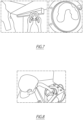
Figure 7 shows the device ofFigure 5 being inspected for air pockets; -
Figure 8 shows the device ofFigure 5 being placed in a curing flask; -
Figure 9 shows the device ofFigure 5 after the soft lining has been milled; -
Figure 10 shows the device ofFigure 9 after milling with burs being removed by dry ice; -
Figure 11 shows a 3D printed version of the device ofFigure 1 ; -
Figure 12 shows another cross-section view of an intraoral device; and -
Figure 13 shows another cross-section view of an intraoral device. - One form of a known intraoral device is disclosed in International Patent Publication No.
WO2017/106896 . This publication relates to a form of intraoral device known as a mandibular advancement splint (MAS) or mandibular advancement device for the treatment of snoring and obstructive sleep apnoea (OSA). This mandibular advancement device includes a lower part and an upper part, which are adapted to be fitted to the respective upper and lower jaw of a patient for use in sleep. The various parts of this mandibular advancement device are designed to advance the lower jaw of a patient in an anterior direction, thereby carrying the tongue forward and reducing the likelihood of the tongue impacting on the airway of the patient. The present invention could be used to make such a device. - Referring to
Figures 2 ,11, 12 and 13 , for example, a typical intraoral device 1 includes abody 5 formed from a relatively rigid material such as acrylic, polyamide, polycarbonate or the like. Thebody 5 is adapted to be fitted in the oral cavity of a patient. Thebody 5 typically includes a front central portion 7 and a pair of longitudinally extending arms 8, 9. Acavity 11 extends along the central portion and arms and includes abase 12 and upwardly extendingwalls 13 as best seen inFigure 2 . Thebase 12 is adapted to be moulded to the shape of the patient's teeth. - The manufacturing of the intraoral device 1 will now be described with reference to the drawings and images.
- An impression of a patient's teeth can be acquired from a physical record taken with polyvinyl siloxane (PVS) or similar material that is then poured up and digitised. Preferably, the physical record is acquired digitally using an intraoral scan of the teeth or a cone beam computed tomography (CBCT) scan of the teeth. For mandibular advancement splints (MAS) or devices, the dentist may use a bite gauge tool to capture a protrusive relationship. Once the impression of the patient's teeth is obtained in a digital form, the impression is uploaded to a repository of cases to be processed. The files are inspected for defects such as incomplete scan, warps or defects. Assuming that these files pass the requirements, computer-aided design (CAD) software is used to design at least two bodies, formed from a hard and a soft material. These CAD files are exported as STL or similar file type and then imported into milling software. One or more of the processors may be utilised during the process. The multiple milling stages are calculated in computer numerical control (CNC) software at a similar time, taking care to ensure that the files are not misaligned. Referring to
Figure 1 , for example, the technician would take a blank 20 of suitable, preferably rigid and/or hard structural material (such as PMMA or polyamide) and mill (or otherwise remove material from the blank as shown inFigure 1 ), using a milling machine, thecavity 11 in the general form of teeth. Themilled cavity 11 would be offset from the accurate impression by 0.5 to 1.5mm. This may also be known as a first general milling run. - As best seen in
Figure 2 , thewalls 13 of thecavity 11 include ashelf 22 to accommodate aflange 25 of a soft lining or insert 26. In other words, the soft lining or insert 26 is adapted to fill thecavity 11. The soft lining or insert 26 may be an elastomeric material such as silicone, plasticized acrylic, thermoplastic polyurethane, or vinyl copolymers. The soft lining or insert 26 may alternatively be a heat formable material such as polycaprolactone. It will be understood that the soft lining or insert 26 is soft relative to the material of the blank 20. Theflange 25 may at least increase the surface area of the soft lining or insert 26 and mitigate failure of the bonding of the twomaterials soft lining 26 and the hard surface (body) 5. This arrangement may also prevent the problem of delamination during the milling process.Multiple shelves 22 formingretention grooves 40 may be present, for example, as seen inFigure 12 . The soft lining or insert 26 at the base 12 facing thecavity 11 has afit surface 14 that is cleaned (or prepared with a primer, bond agent, plasma surface treatment, sand blasting treatment or the like) and thecavity 11 is packed completely or partially, manually or with the aid of a machine as see inFigure 3 . At this step care must be taken while applying thesoft lining material 26 to remove air pockets, particularly when thesoft lining material 26 is viscous to facilitate the filling of thecavity 11. If air pockets exist, they can be lanced/pierced using a probe or the like as shown inFigure 6 providing a path for air to escape before being recompressed (Figure 8 ). The soft lining or insert 26 may alternately be pressed under forces using pneumatic press, vacuum chambers or other like pressurised application methods (mechanical or hydraulic) as shown inFigures 4 and8 . The shelf orshelves 22 could also be milled in the reverse configuration as shown inFigure 13 . - As seen in
Figure 7 , the filled in blank 20 can be held up to the light to check for air pockets. The filled in blank 20, along with the soft lining orinsert 26, as shown inFigure 8 is then cured at relevant processing conditions for the soft lining orinsert 26. This may involve water, heat, light and/or pressure as per supplier instructions. - As seen in
Figure 9 , thesoft lining material 26 is then milled or machined to the desired dimensions of the impression using a specialised cutter. A specialised cutter would change depending upon the type ofsoft lining material 26 that is being utilised. The cutter may, for example, have a ball head geometry with a plurality of blades extending radially from the ball head. - The blank 20 is then rotated and the excess hard material is removed to form the
body 5, thus obtaining the shape of the device 1. Any minor burrs remaining after milling may be removed (thereby cleaning the device) using a micro motor hand piece or the like with a brush burr, or alternatively may be removed using dry ice CO2 blasting or the like, as shown inFigure 10 . The blank 20 and/or thebody 5 may have a thickness of between 0.5 to 4.0mm and/or a flexural modulus of between 1000 MPa and 4000 MPa. Thesoft lining material 26 may have a Shore A hardness of between 55 and 99. - It will be appreciated that a method of manufacturing an intraoral device may include (and is not limited to) any one or more of the following steps:
- obtaining an impression of at least one row of a patient's teeth;
- transferring said impression into a processor;
- said processor communicating with a milling machine;
- milling a blank of a first material to form a cavity in said blank substantially
- corresponding to said impression, said cavity being milled to include an offset;
- filling said cavity with at least a second material and allowing said second material to cure;
- milling said second material to correspond to said impression;
- milling said first material to obtain a device shape;
- cleaning said device; and wherein
said first and second materials are comparatively hard and soft. - In alternate embodiments, the full shape of the
body 5 of the device 1 is obtained by milling the blank 20. The soft lining or insert 11 is then added to thecavity 11, and subsequently milled or machined to the desired impression. In further alternate embodiments, instead of using a blank and milling, thebody 5 of the device 1 could be 3D printed using acrylic, polyamide, polycarbonate using technology such as FDM, SLS, DLP as generally shown. The offset of 0.5mm to 1.5mm may still be provided, and the 3D printer could also include a locator 30 (seeFigure 11 ) for assistance to the technicians. Thecavity 11 could then be packed with thesoft lining material 26 or sucked down. The device 1 could then follow the usual steps of the milling, locating using thefixtures 30 and mill thefit surface 14. - As mentioned above, a suckdown method could also be used using a suitable structural material such as PMMA or polyamide with an offset to accommodate the soft lining as mentioned above. In this case one or more air holes would be used at the central portion 7 and arms 8 and 9 for air to escape. A primer would then be applied along with a bonding agent then the suckdown dual laminate would occur.
- The present invention at least in a preferred embodiment has significant advantages over the prior art. For example, it may at least provide comfort for the patient (soft lining plus strength) with greater compliance to the patient's teeth and fewer breakages. The method may also provide enhanced accuracy of fit, which may again lead to greater patient comfort, fewer areas of high contact pressure and more even pressure across the teeth. Due to the enhanced accuracy, there is also less tooth movement.
- The method may also provide a lower risk of delamination than traditional suckdown methods due to the shelf/lip design and lancing technique, which provides a longer life device. There is a reduced need for remakes, and no physical working model is required, thus saving costs and by-products.
- Alternative embodiments could include using dry ice CO2 blasting to remove the burrs left on a fit surface, instead of manually doing the same with a micro motor and brush burr and also applying the technique to 3D printed parts as mentioned above. Further, the soft lining material can be deposited/dispensed by CNC robotic dispensing systems, thus providing less waste instead of packing the cavity with greater control dispensing amount of material required on marginally more than required. Greater control equals fewer errors as the process is automated, and new materials may also become available for use, instead of only acrylic or polyamide. Plasma surface treatment or sand blasting may also improve the soft lining bond strength. The milling of the soft lining material is particularly advantageous.
- Accordingly, the present invention at least in the preferred embodiment may at least provide an extremely precise fitting of a dual material device fabricated digitally and automatically. The arrangement may at least remove most (if not all) human errors and remove inherent errors from the expansion and contraction of materials which are characteristics of traditional processes. The highly desirable characteristics of dual laminate materials may at least provide a balance of flexibility and comfort including strength and durability. The device could, in a preferred form, be a sleep apnea device. However, the device could also be a bruxism splint, mouthguard, denture, hearing aid or the like.
- Although the invention has been described with reference to preferred embodiments, it will be appreciated by those persons skilled in the art that the invention may be embodied in many other forms.
Claims (22)
- A method of manufacturing an intraoral device (1) including:obtaining an impression of at least one row of a patient's teeth;transferring said impression into a processor;said processor either:a) communicating with a milling machine; and
milling a blank (20) of a first material to form a cavity (11) in said blank (20) substantially corresponding to said impression, said cavity (11) being milled to include an offset from the impression; ORb) communicating with a 3D printing machine and a milling machine; and 3D printing a first material to form a cavity (11) with an offset substantially corresponding to said impression;the method further including filling said cavity (11) with at least a second material and allowing said second material to cure;milling said second material to correspond to said impression;milling said first material to obtain a device shape; and whereinsaid first and second materials are comparatively hard and soft. - The method of claim 1, wherein the method further comprises cleaning said device (1).
- The method of claim 1, whereinsaid processor communicates with the milling machine; and the milling machine mills the blank (20) of the first material to form the cavity (11) in said blank (20) substantially corresponding to said impression, said cavity (11) being milled to include the offset; wherein the method further comprisesforming by pressure and/or heat a foil over the cavity (11);then milling the cavity (11);placing the foil over the blank (20) to form a closed volume;then filling volume closed with the second material and allowing said second material to cure.
- The method of any one of claims 1 to 3, wherein said offset is 0.5mm to 1.5mm.
- The method of any one of claims 1 to 4, wherein said cavity (11) includes a base (12), upwardly extending side walls (13) to a lip, said lip including one or more shelves.
- The method of any one of claims 1 to 5, wherein said first material is a relatively rigid polymer such as acrylic, polyamide or polycarbonate.
- The method of any one of claims 1 to 6, wherein the cavity surface is sandblasted.
- The method of any one of claims 1 to 7, wherein a primer or bonding agent is applied to the cavity surface.
- The method of any one of claims 1 to 8, wherein said second material is an elastomeric material such as silicone, plasticized acrylic, thermoplastic polyurethane or vinyl copolymers.
- The method of any one of claims 1 to 9, wherein said second material is a heat formable material such as polycaprolactone.
- The method of any one of claims 1 to 10, wherein said device is CNC milled.
- The method of any one of claims 1 to 11, wherein the filling of the second material is a partial filling of the cavity, to reduce material wastage.
- The method of any one of claims 1 to 12, wherein the second material is viscous, and after filling, any air pockets located within said second material is removed prior to curing.
- The method of any one of claims 1 to 13, wherein the second material is formed by thermoforming.
- The method of any one of claims 1 to 14, wherein said device (1) is cleaned using a micromotor tool.
- The method of any one of claims 1 to 15, wherein said device is cleaned using dry ice.
- The method of any one of claims 1 to 16, wherein the thickness of the first material is between 0.5mm and 4.0mm.
- The method of any one of claims 1 to 17, wherein the thickness of the second material is between 0.5 and 1.5mm.
- The method of any one of claims 1 to 18, wherein the flexural modulus of the first material is between 1000 MPa and 4000MPa.
- The method of any one of claims 1 to 19, wherein the Shore A hardness of the second material is between 55 and 99.
- The method of any one of claims 1 to 20, wherein the device (1) is a mouthguard.
- The method of any one of claims 1 to 21, where a cutter used to mill or machine the second material has a ball head geometry with a plurality of blades radially extending from the ball.
Applications Claiming Priority (2)
| Application Number | Priority Date | Filing Date | Title |
|---|---|---|---|
| AU2019901867A AU2019901867A0 (en) | 2019-05-30 | A method of manufacturing an intraoral device | |
| PCT/AU2020/050542 WO2020237316A1 (en) | 2019-05-30 | 2020-05-29 | A method of manufacturing an intraoral device |
Publications (4)
| Publication Number | Publication Date |
|---|---|
| EP3972524A1 EP3972524A1 (en) | 2022-03-30 |
| EP3972524A4 EP3972524A4 (en) | 2023-05-10 |
| EP3972524C0 EP3972524C0 (en) | 2024-08-28 |
| EP3972524B1 true EP3972524B1 (en) | 2024-08-28 |
Family
ID=73551932
Family Applications (1)
| Application Number | Title | Priority Date | Filing Date |
|---|---|---|---|
| EP20814818.9A Active EP3972524B1 (en) | 2019-05-30 | 2020-05-29 | Method of manufacturing an intraoral device |
Country Status (4)
| Country | Link |
|---|---|
| US (1) | US12558255B2 (en) |
| EP (1) | EP3972524B1 (en) |
| ES (1) | ES2994837T3 (en) |
| WO (1) | WO2020237316A1 (en) |
Families Citing this family (1)
| Publication number | Priority date | Publication date | Assignee | Title |
|---|---|---|---|---|
| US12558255B2 (en) | 2019-05-30 | 2026-02-24 | Somnomed Limited | Method of manufacturing an intraoral device |
Family Cites Families (18)
| Publication number | Priority date | Publication date | Assignee | Title |
|---|---|---|---|---|
| US7293988B2 (en) * | 2004-12-14 | 2007-11-13 | Align Technology, Inc. | Accurately predicting and preventing interference between tooth models |
| AU2006220803A1 (en) * | 2005-03-07 | 2006-09-14 | Align Technology, Inc. | Variations of dental aligners |
| US20070183572A1 (en) * | 2006-01-13 | 2007-08-09 | Arielle Drummond | Apparatus and method for manufacturing a mandibular advancement device |
| GB201216230D0 (en) * | 2012-09-12 | 2012-10-24 | Nobel Biocare Services Ag | An improved surgical template |
| GB201216214D0 (en) * | 2012-09-12 | 2012-10-24 | Nobel Biocare Services Ag | A digital splint |
| US11207207B2 (en) * | 2013-12-30 | 2021-12-28 | Prosomnus Sleep Technologies Inc. | Mandibular advancement device |
| MX2017006456A (en) * | 2014-11-17 | 2018-03-12 | D Williams Edward | Low profile articulation jaw joint stabilizer device. |
| US10874483B2 (en) | 2015-07-07 | 2020-12-29 | Align Technology, Inc. | Direct fabrication of attachment templates with adhesive |
| US20170007442A1 (en) * | 2015-07-11 | 2017-01-12 | Thermal Fit, LLC | Intraoral Orthosis Device and Method for Manufacturing |
| US9655695B2 (en) * | 2015-08-06 | 2017-05-23 | Gregory K. Ross | Oral apparatuses and methods for mandibular jaw manipulation |
| US9744006B2 (en) * | 2015-08-06 | 2017-08-29 | Gregory K. Ross | Oral apparatuses and methods for mandibular jaw manipulation |
| DE102015222821B4 (en) * | 2015-11-19 | 2026-05-07 | Sirona Dental Systems Gmbh | Method and apparatus for operating a dental diagnostic imaging system |
| WO2017106896A1 (en) | 2015-12-22 | 2017-06-29 | Somnomed Limited | A mandibular advancement device |
| WO2018017488A1 (en) * | 2016-07-22 | 2018-01-25 | ProSomnus Sleep Technologies, Inc. | Computer aided design matrix for the manufacture of dental devices |
| EP3496656B1 (en) * | 2016-08-10 | 2020-06-10 | Ivoclar Vivadent AG | Method for producing a prosthesis or partial prosthesis |
| WO2018218229A2 (en) * | 2017-05-26 | 2018-11-29 | Diamond Orthotic Laboratory | Systems, methods and oral appliance devices |
| US11224500B2 (en) * | 2018-03-14 | 2022-01-18 | James R. Glidewell Dental Ceramics, Inc. | Oral device, manufacturing apparatus and methods of making the same |
| US12558255B2 (en) | 2019-05-30 | 2026-02-24 | Somnomed Limited | Method of manufacturing an intraoral device |
-
2020
- 2020-05-29 US US17/595,933 patent/US12558255B2/en active Active
- 2020-05-29 WO PCT/AU2020/050542 patent/WO2020237316A1/en not_active Ceased
- 2020-05-29 EP EP20814818.9A patent/EP3972524B1/en active Active
- 2020-05-29 ES ES20814818T patent/ES2994837T3/en active Active
Also Published As
| Publication number | Publication date |
|---|---|
| ES2994837T3 (en) | 2025-02-03 |
| US20220226146A1 (en) | 2022-07-21 |
| EP3972524A1 (en) | 2022-03-30 |
| EP3972524C0 (en) | 2024-08-28 |
| WO2020237316A1 (en) | 2020-12-03 |
| US12558255B2 (en) | 2026-02-24 |
| EP3972524A4 (en) | 2023-05-10 |
Similar Documents
| Publication | Publication Date | Title |
|---|---|---|
| US12383377B2 (en) | Methods for designing attachment placement appliances | |
| EP3853011B1 (en) | Devices and method for removing a shell from a mould | |
| US7831322B2 (en) | Producing wrinkled dental aligner for dental treatment | |
| US20060199142A1 (en) | Dental aligner for providing accurate dental treatment | |
| US20220031426A1 (en) | Direct fabrication of mixed metal and polymer orthodontic devices | |
| US20060199140A1 (en) | Disposable dental aligner | |
| JP2016509907A (en) | Retainer and method for manufacturing the retainer | |
| US11337780B1 (en) | Clear aligner attachment system and method | |
| JP2014133134A (en) | Direct manufacture of orthodontic aligner appliance | |
| US12251276B2 (en) | Additively manufactured denture base with bracing body | |
| CN106137416A (en) | Combined orthodontic system and manufacture method thereof | |
| CN111182851B (en) | Removable dental appliance including a jumper wire | |
| US12558255B2 (en) | Method of manufacturing an intraoral device | |
| EP4512362A1 (en) | Splints for injected veneers | |
| US20220323180A1 (en) | Method for making hard clear aligner set for stepwise orthodontic treatment | |
| CN117838339A (en) | Method for manufacturing shell-shaped dental appliance, shell-shaped dental appliance and dental model |
Legal Events
| Date | Code | Title | Description |
|---|---|---|---|
| STAA | Information on the status of an ep patent application or granted ep patent |
Free format text: STATUS: THE INTERNATIONAL PUBLICATION HAS BEEN MADE |
|
| PUAI | Public reference made under article 153(3) epc to a published international application that has entered the european phase |
Free format text: ORIGINAL CODE: 0009012 |
|
| STAA | Information on the status of an ep patent application or granted ep patent |
Free format text: STATUS: REQUEST FOR EXAMINATION WAS MADE |
|
| 17P | Request for examination filed |
Effective date: 20211220 |
|
| AK | Designated contracting states |
Kind code of ref document: A1 Designated state(s): AL AT BE BG CH CY CZ DE DK EE ES FI FR GB GR HR HU IE IS IT LI LT LU LV MC MK MT NL NO PL PT RO RS SE SI SK SM TR |
|
| DAV | Request for validation of the european patent (deleted) | ||
| DAX | Request for extension of the european patent (deleted) | ||
| A4 | Supplementary search report drawn up and despatched |
Effective date: 20230412 |
|
| RIC1 | Information provided on ipc code assigned before grant |
Ipc: A61C 7/08 20060101AFI20230404BHEP |
|
| GRAP | Despatch of communication of intention to grant a patent |
Free format text: ORIGINAL CODE: EPIDOSNIGR1 |
|
| STAA | Information on the status of an ep patent application or granted ep patent |
Free format text: STATUS: GRANT OF PATENT IS INTENDED |
|
| INTG | Intention to grant announced |
Effective date: 20240319 |
|
| GRAS | Grant fee paid |
Free format text: ORIGINAL CODE: EPIDOSNIGR3 |
|
| GRAA | (expected) grant |
Free format text: ORIGINAL CODE: 0009210 |
|
| STAA | Information on the status of an ep patent application or granted ep patent |
Free format text: STATUS: THE PATENT HAS BEEN GRANTED |
|
| AK | Designated contracting states |
Kind code of ref document: B1 Designated state(s): AL AT BE BG CH CY CZ DE DK EE ES FI FR GB GR HR HU IE IS IT LI LT LU LV MC MK MT NL NO PL PT RO RS SE SI SK SM TR |
|
| REG | Reference to a national code |
Ref country code: CH Ref legal event code: EP |
|
| REG | Reference to a national code |
Ref country code: DE Ref legal event code: R096 Ref document number: 602020036784 Country of ref document: DE |
|
| REG | Reference to a national code |
Ref country code: IE Ref legal event code: FG4D |
|
| U01 | Request for unitary effect filed |
Effective date: 20240925 |
|
| U07 | Unitary effect registered |
Designated state(s): AT BE BG DE DK EE FI FR IT LT LU LV MT NL PT RO SE SI Effective date: 20241018 |
|
| PG25 | Lapsed in a contracting state [announced via postgrant information from national office to epo] |
Ref country code: PL Free format text: LAPSE BECAUSE OF FAILURE TO SUBMIT A TRANSLATION OF THE DESCRIPTION OR TO PAY THE FEE WITHIN THE PRESCRIBED TIME-LIMIT Effective date: 20240828 Ref country code: GR Free format text: LAPSE BECAUSE OF FAILURE TO SUBMIT A TRANSLATION OF THE DESCRIPTION OR TO PAY THE FEE WITHIN THE PRESCRIBED TIME-LIMIT Effective date: 20241129 |
|
| PG25 | Lapsed in a contracting state [announced via postgrant information from national office to epo] |
Ref country code: IS Free format text: LAPSE BECAUSE OF FAILURE TO SUBMIT A TRANSLATION OF THE DESCRIPTION OR TO PAY THE FEE WITHIN THE PRESCRIBED TIME-LIMIT Effective date: 20241228 |
|
| PG25 | Lapsed in a contracting state [announced via postgrant information from national office to epo] |
Ref country code: HR Free format text: LAPSE BECAUSE OF FAILURE TO SUBMIT A TRANSLATION OF THE DESCRIPTION OR TO PAY THE FEE WITHIN THE PRESCRIBED TIME-LIMIT Effective date: 20240828 |
|
| PG25 | Lapsed in a contracting state [announced via postgrant information from national office to epo] |
Ref country code: RS Free format text: LAPSE BECAUSE OF FAILURE TO SUBMIT A TRANSLATION OF THE DESCRIPTION OR TO PAY THE FEE WITHIN THE PRESCRIBED TIME-LIMIT Effective date: 20241128 |
|
| PG25 | Lapsed in a contracting state [announced via postgrant information from national office to epo] |
Ref country code: RS Free format text: LAPSE BECAUSE OF FAILURE TO SUBMIT A TRANSLATION OF THE DESCRIPTION OR TO PAY THE FEE WITHIN THE PRESCRIBED TIME-LIMIT Effective date: 20241128 Ref country code: PL Free format text: LAPSE BECAUSE OF FAILURE TO SUBMIT A TRANSLATION OF THE DESCRIPTION OR TO PAY THE FEE WITHIN THE PRESCRIBED TIME-LIMIT Effective date: 20240828 Ref country code: IS Free format text: LAPSE BECAUSE OF FAILURE TO SUBMIT A TRANSLATION OF THE DESCRIPTION OR TO PAY THE FEE WITHIN THE PRESCRIBED TIME-LIMIT Effective date: 20241228 Ref country code: HR Free format text: LAPSE BECAUSE OF FAILURE TO SUBMIT A TRANSLATION OF THE DESCRIPTION OR TO PAY THE FEE WITHIN THE PRESCRIBED TIME-LIMIT Effective date: 20240828 Ref country code: GR Free format text: LAPSE BECAUSE OF FAILURE TO SUBMIT A TRANSLATION OF THE DESCRIPTION OR TO PAY THE FEE WITHIN THE PRESCRIBED TIME-LIMIT Effective date: 20241129 |
|
| REG | Reference to a national code |
Ref country code: ES Ref legal event code: FG2A Ref document number: 2994837 Country of ref document: ES Kind code of ref document: T3 Effective date: 20250203 |
|
| PG25 | Lapsed in a contracting state [announced via postgrant information from national office to epo] |
Ref country code: SM Free format text: LAPSE BECAUSE OF FAILURE TO SUBMIT A TRANSLATION OF THE DESCRIPTION OR TO PAY THE FEE WITHIN THE PRESCRIBED TIME-LIMIT Effective date: 20240828 |
|
| PG25 | Lapsed in a contracting state [announced via postgrant information from national office to epo] |
Ref country code: CZ Free format text: LAPSE BECAUSE OF FAILURE TO SUBMIT A TRANSLATION OF THE DESCRIPTION OR TO PAY THE FEE WITHIN THE PRESCRIBED TIME-LIMIT Effective date: 20240828 |
|
| PG25 | Lapsed in a contracting state [announced via postgrant information from national office to epo] |
Ref country code: SK Free format text: LAPSE BECAUSE OF FAILURE TO SUBMIT A TRANSLATION OF THE DESCRIPTION OR TO PAY THE FEE WITHIN THE PRESCRIBED TIME-LIMIT Effective date: 20240828 |
|
| U20 | Renewal fee for the european patent with unitary effect paid |
Year of fee payment: 6 Effective date: 20250424 |
|
| PLBE | No opposition filed within time limit |
Free format text: ORIGINAL CODE: 0009261 |
|
| STAA | Information on the status of an ep patent application or granted ep patent |
Free format text: STATUS: NO OPPOSITION FILED WITHIN TIME LIMIT |
|
| PGFP | Annual fee paid to national office [announced via postgrant information from national office to epo] |
Ref country code: GB Payment date: 20250401 Year of fee payment: 6 Ref country code: ES Payment date: 20250606 Year of fee payment: 6 |
|
| PGFP | Annual fee paid to national office [announced via postgrant information from national office to epo] |
Ref country code: NO Payment date: 20250509 Year of fee payment: 6 |
|
| PGFP | Annual fee paid to national office [announced via postgrant information from national office to epo] |
Ref country code: CH Payment date: 20250601 Year of fee payment: 6 |
|
| PGFP | Annual fee paid to national office [announced via postgrant information from national office to epo] |
Ref country code: IE Payment date: 20250402 Year of fee payment: 6 |
|
| 26N | No opposition filed |
Effective date: 20250530 |
|
| PG25 | Lapsed in a contracting state [announced via postgrant information from national office to epo] |
Ref country code: MC Free format text: LAPSE BECAUSE OF FAILURE TO SUBMIT A TRANSLATION OF THE DESCRIPTION OR TO PAY THE FEE WITHIN THE PRESCRIBED TIME-LIMIT Effective date: 20240828 |