EP3972403B1 - Landwirtschaftliches scheibenmesser mit kerbenkante auf stufenebene - Google Patents
Landwirtschaftliches scheibenmesser mit kerbenkante auf stufenebene Download PDFInfo
- Publication number
- EP3972403B1 EP3972403B1 EP19929358.0A EP19929358A EP3972403B1 EP 3972403 B1 EP3972403 B1 EP 3972403B1 EP 19929358 A EP19929358 A EP 19929358A EP 3972403 B1 EP3972403 B1 EP 3972403B1
- Authority
- EP
- European Patent Office
- Prior art keywords
- disc
- blade
- agricultural tillage
- hub
- agricultural
- Prior art date
- Legal status (The legal status is an assumption and is not a legal conclusion. Google has not performed a legal analysis and makes no representation as to the accuracy of the status listed.)
- Active
Links
Images


Classifications
-
- A—HUMAN NECESSITIES
- A01—AGRICULTURE; FORESTRY; ANIMAL HUSBANDRY; HUNTING; TRAPPING; FISHING
- A01B—SOIL WORKING IN AGRICULTURE OR FORESTRY; PARTS, DETAILS, OR ACCESSORIES OF AGRICULTURAL MACHINES OR IMPLEMENTS, IN GENERAL
- A01B7/00—Disc-like soil-working implements usable either as ploughs or as harrows, or the like
-
- A—HUMAN NECESSITIES
- A01—AGRICULTURE; FORESTRY; ANIMAL HUSBANDRY; HUNTING; TRAPPING; FISHING
- A01B—SOIL WORKING IN AGRICULTURE OR FORESTRY; PARTS, DETAILS, OR ACCESSORIES OF AGRICULTURAL MACHINES OR IMPLEMENTS, IN GENERAL
- A01B15/00—Elements, tools, or details of ploughs
- A01B15/16—Discs; Scrapers for cleaning discs; Sharpening attachments
-
- A—HUMAN NECESSITIES
- A01—AGRICULTURE; FORESTRY; ANIMAL HUSBANDRY; HUNTING; TRAPPING; FISHING
- A01B—SOIL WORKING IN AGRICULTURE OR FORESTRY; PARTS, DETAILS, OR ACCESSORIES OF AGRICULTURAL MACHINES OR IMPLEMENTS, IN GENERAL
- A01B15/00—Elements, tools, or details of ploughs
- A01B15/18—Coulters
-
- A—HUMAN NECESSITIES
- A01—AGRICULTURE; FORESTRY; ANIMAL HUSBANDRY; HUNTING; TRAPPING; FISHING
- A01C—PLANTING; SOWING; FERTILISING
- A01C5/00—Making or covering furrows or holes for sowing, planting or manuring
- A01C5/06—Machines for making or covering drills or furrows for sowing or planting
- A01C5/062—Devices for making drills or furrows
- A01C5/064—Devices for making drills or furrows with rotating tools
-
- A—HUMAN NECESSITIES
- A01—AGRICULTURE; FORESTRY; ANIMAL HUSBANDRY; HUNTING; TRAPPING; FISHING
- A01B—SOIL WORKING IN AGRICULTURE OR FORESTRY; PARTS, DETAILS, OR ACCESSORIES OF AGRICULTURAL MACHINES OR IMPLEMENTS, IN GENERAL
- A01B21/00—Harrows with rotary non-driven tools
- A01B21/08—Harrows with rotary non-driven tools with disc-like tools
Definitions
- This disclosure relates generally to an improved ground engaging blade for an agricultural implement such as a tillage disc or coulter, drill or planter, and more particularly to such a blade that, due to this shape, resists throwing and provides a consistent cut.
- Coulters are presently used ahead of no-till implements-such as a planter---to fracture a narrow band of soil to prepare the soil to receive the no-till implement.
- U.S. Pat. No. 7,497,270 to Bruce shows coulters and one way of how they are used to till and open the soil.
- a disc can be a flat coulter that is deformed to a convex shape on one side and concave shape on the other side so it will throw soil in one direction as it moves forwardly through the ground.
- Discs are most often used with a plurality of them side by side in "gangs" or rows as shown in U.S. Pat. No. 6,554,079 to Bruce .
- US 2015/289433 A1 discloses a wavy disc blade including a first side, a second side, a central portion having at least one opening, and a wavy portion adjacent to, extending radially from and circumferentially about the central portion.
- the wavy portion includes a plurality of waves extending from the central portion to an edge portion, the waves forming a plurality of crests and valleys between the central portion and the edge portion.
- the wavy disc blade also includes a plurality of teeth formed along the edge portion. At least one of a first beveled portion may be formed on the first side at and along the edge portion and a second beveled portion may be formed on the second side at and along the edge portion.
- US 2021/103642 A1 discloses a disc for an agricultural implement comprising an annular, outside a predetermined centre diameter defined, soil-cultivating portion, a central, inside a predetermined centre diameter defined, dish-shaped portion, with a boss-receiving, inner side and between these portions an existing, annular connection portion with fastening screw holes.
- the connection portion is a truncated conical portion, the inner mantle surface of which is mainly straight or double-bowed with the convex side facing said inner side and a line through the opening plane in the hole opening of each fastening screw hole on said inner side forms an angle ⁇ with a plane that is perpendicular to the centre line of the disc, wherein the angle ⁇ is 5°-10°.
- US 2 749 649 A discloses a reversible disc harrow for detachable attachment to a tractor and comprising the combination of an implement frame, means for detachably connecting said implement frame to the tractor, a pair of disc gangs adapted to be reversed between an outthrow and an inthrow position, hinge means disposed between said implement frame and each said gang providing bodily tilt of the latter about a generally horizontal axis spaced below said implement frame and also providing swivel movement of each said gang from an outthrow to an inthrow position about a generally upright axis offset rearwardly from the rotational axis of the individual discs in said gang, a first positive locking means for maintaining each said gang in a selected condition of tilt with said gang in its outthrow as well as its inthrow position, and a second positive locking means for maintaining each said gang in a selected condition of angling adjustment with said gang in outthrow as well as in inthrow position, said second positive locking means including a pair of
- US 2016/00001 A1 discloses an agricultural tillage blade having a central opening is adapted to be disposed on a shaft for rotation to cut trash and penetrate into the soil.
- the blade has an outer periphery substantially in the shape of a sine curve formed about a circle. The outer periphery of the blade is sharpened to more easily penetrate the soil and cut trash.
- CN 109 451 885 A discloses an independent plough coulter arm assembly, which comprises a notch harrow blade, a plough coulter arm, a hub unit, V-shaped plates and a rubber suspension; the hub unit is arranged at the central hole of the notch harrow blade; one end of the plough coulter arm is fixedly connected with a shaft of the hub unit, and the other end of the plow coulter arm is provided with a V-shaped opening; the two V-shaped plates are connected into a whole in the opposite direction of the V-shaped opening, one of the V-shaped plates is embedded and welded on the V-shaped opening of theplough coulter arm, a machine square pipe penetrates through the space between the two V-shaped plates, and the rubber is suspended is filled in the gap between the machine square pipe and the two V-shaped plates.
- each coulter head works independently, and the depth of cultivated land is adjusted through the buffering action when the coulter head cultivates on the ground with different heights, so that the maintenance in the use process is achieved, and the time is effectively saved; the independent plough coulter arm has higher strength and impact resistance, can provide a perfect working state even under the worst environment, and improves the tillage effect and efficiency.
- a ground engaging agricultural tillage blade according to the subject-matter of claim 1 is provided. Further embodiments are disclosed according to the subject-matter of the dependent claims.
- the disclosure also relates to an apparatus for an agricultural implement blade.
- the blade is a disc or coulter that is generally circular with an outer periphery.
- a plurality of step plane notches are disposed in the outer periphery of the disc, each of the plurality of step plane notches tapering from a predetermined thickness on a radial inside to a thinner generally sharped edge at the radially outermost part thereof.
- each step plane notch has a uniformly deep and sharpened edge so as to provide consistent penetration and residue sizing of the ground with a reduced amount of soil throwing.
- the disc can be generally curved, a flat coulter, or a disc that is convex on one side and concave on the other side.
- the present disclosure provides a ground engaging agricultural tillage blade comprising: a disc having a central opening adapted to be attached to an implement for rotation about an axis of rotation; the disc having an outer periphery; and characterized by further comprising: a plurality of step plane notches in the disc from a location substantially at the outer periphery to the central opening; wherein each of the plurality of step plane notches comprises a depth and a width, wherein the depth is 50% or less than the width, and wherein the step plane notches are of uniform depth.
- the present disclosure provides a ground engaging agricultural tillage blade apparatus characterized by comprising: a ground engaging agricultural tillage blade according to the first aspect; and a hub being attached to the disc around the central opening.
- the present disclosure provides a ground engaging agricultural tillage blade apparatus characterized by comprising: at least two ground engaging agricultural tillage blades according to the first aspect; and wherein a spacer spool is disposed on a shaft between the discs of the at least two ground engaging agricultural tillage blades, the spacer spool extending radially outwardly from the center opening of each disc.
- the agricultural blade apparatus comprises an agricultural blade 10.
- Each blade 10 may be of any diameter and thickness and may be constructed out of any suitable material.
- the blade 10 is of a diameter that is preferably 43.18 cm to 101.6 cm (17 inches to 40 inches).
- the blade 10 is preferably 4.572 mm to 12.7 mm (0.180 inches to 0.5 inches) in thickness.
- the agricultural blade may be of any diameter and thickness without departing from the scope of the appended claims.
- the blade 10 is constructed out of any suitable material, including, but not limited to, metal, steel, hard plastics, and the like.
- Each blade 10 further comprises an outer periphery 18.
- the agricultural blade apparatus comprises an agricultural blade 10.
- the agricultural blade 10 is a disc 12, which may be convex on one side and concave on the other side.
- Each disc 12 may be of any diameter and thickness and may be constructed out of any suitable material.
- the disc 12 is of a diameter that is preferably 43.18 cm to 101.6 cm (17 inches to 40 inches).
- the disc 12 is preferably 4.572 mm to 12.7 mm (0.180 inches to 0.5 inches) in thickness.
- the disc may be of any diameter and thickness without departing from the scope of the appended claims.
- the disc 12 is constructed out of any suitable material, including, but not limited to, metal, steel, hard plastics, and the like.
- Each disc 12 further comprises an outer periphery 18.
- the agricultural blade apparatus comprises an agricultural blade 10.
- the agricultural blade 10 is a coulter 14, which is substantially flat.
- Each coulter 14 may be of any diameter and thickness and may be constructed out of any suitable material.
- the coulter 14 is of a diameter that is preferably 43.18 cm to 101.6 cm (17 inches to 40 inches).
- the coulter 14 is preferably 3.175 mm to 12.7 mm (0.125 inches to 0.5 inches) in thickness.
- the coulter 14 is constructed out of any suitable material, including, but not limited to, metal, steel, hard plastics, and the like.
- Each coulter 14 further comprises an outer periphery 18.
- the agricultural blade apparatus comprises an agricultural blade 10.
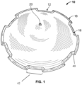
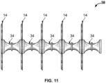
- the agricultural blade 10 further comprises a step plane notch 16, and preferably a plurality of step plane notches 16 disposed in the outer periphery 18 of the agricultural blade 10.
- the agricultural blade comprises at least five step plane notches 16.
- the angle of opening of each notch 16 disposed in the outer periphery 18 is preferably 80 degrees to 135 degrees, or any angle which is suitable for reduction of throwing and promotion of consistent cuts.
- the notches 16 can be of other shapes and sizes. It is preferable that each notch 16 be the same shape to promote uniform wear. Further, it is preferable that the plurality of notches 16 are equally spaced in the outer periphery 18. In a preferred embodiment, spacing should be provided such that each third of the agricultural blade 10 contains at least one notch, preferably at least one and half notches, and preferably at least two notches.
- the agricultural blade apparatus comprises an agricultural blade 10 wherein the agricultural blade 10 comprises a step plane notch 16, and preferably a plurality of step plane notches 16 disposed in the outer periphery 18 of the agricultural blade 10.
- the agricultural blade 10 comprises a plurality of step plane notches 16 wherein every other step plane notch 16 is sharpened on the opposite side.
- the agricultural blade 10 comprises a plurality of step plane notches 16 wherein every step plane notch 16 is sharpened on both sides.
- the agricultural blade 10 comprises a plurality of step plane notches 16 wherein every step plane notch 16 is sharpened on the same side.
- step plane notches 16 Any variation of sharpening the step plane notches 16 including, but not limited to, every step plane notch 16 being sharpened alike or each step plane notch 16 being sharpened in its own unique manner (i.e., being sharpened on one side, being sharpened on both sides, etc.) may be utilized by the agricultural blade apparatus without departing from the scope of the appended claims. Furthermore, the step plane notches 16 remain sharp longer than other blades.
- the agricultural blade 10 comprises a plurality of step plane notches 16 which may be uniform in depth 40 and sharpness so that any forces applied to the outer periphery 18 will be transmitted evenly so as to avoid inconsistency in the cut made by the blade 10, whether it is a disc or a coulter.
- the agricultural blade 10 comprises a plurality of step plane notches 16 that may vary in depth 40 and sharpness.
- the agricultural blade 10 comprises a plurality of step plane notches 16 wherein each step plane notch 16 comprises a depth 40 which is 50% or less of the width 42 of the notch 16.
- the agricultural blade 10 comprises a plurality of step plane notches 16 of varying depths, but each step plane notch 16 comprises a depth 40 which is 50% or less of the width 42 of the respective notch 16.
- Each of the agricultural blades 10 is provided with a central opening 20 which receives the shaft 32.
- each of the agricultural blades 10 is provided with a central opening 20 which receives the axle 22.
- the central opening 20 may be of any suitable size, shape, and design, so as to accommodate receipt of the shaft 32.
- the shaft 32 and axle 22 may be of any suitable size, shape, and design.
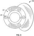
- Each of the agricultural blades 10 is provided with a hub 24 which facilitates receipt of the shaft 32 or axle 22.
- the hub may be of any suitable size, shape, and design.
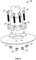
- Spacer spool 34 is formed of any suitable size, shape, and design, and is configured to be positioned between adjacent agricultural blades 10 to facilitate proper spacing of the cuts made by the agricultural implement in the soil.
- Each of the spacer spools 34 comprises a center section and opposite end portions.
- a shaft opening extends through each of the spacer spools 34.
- the end portion can be provided with an annular rim or peripheral portion which is slightly convex so as to be complimentary to the inside curvature of the adjacent disc blade 12 or substantially flat so as to be complimentary to the adjacent coulter blade 14.
- the opposite end portion is also provided with an annular rim or peripheral portion which is slightly concave so as to be complimentary to the outside curvature of the adjacent disc blade 12 or substantially flat so as to be complimentary to the adjacent coulter blade 14.
- one end portion may be slightly smaller in diameter than the opposite end portion since it has been found through experience that the agricultural blades 10 suffer less breakage if spools of different diameters are positioned on opposite sides thereof.
- Threaded fastener 26 is formed of any suitable size, shape, and design, and is configured to tighten against the surface of the hub 24 while also pulling the agricultural blade 10 into firm engagement with the hub 24. The use of a threaded fastener 26 ensures that a seal is formed with the hub 24 and the agricultural blade 10.
- the threaded fastener 26 is a generally cylindrical elongated member having a first threaded end and a head.
- First threaded end and head are in coaxial alignment with one another. That is, the center axis of rotation of the first threaded end and head are in alignment with one another, despite the fact that the diameters or shapes or features of the first threaded end and the head may differ.
- First threaded end and head may have the same diameter or different diameters.
- head positioned in the end of the threaded fastener 26.
- Head is any feature or device that allows for the threaded fastener 26 to be grasped and rotation to be imparted on the threaded fastener 26.
- head is generally cylindrical in shape and has a diameter slightly larger than the diameter of the first threaded end.
- This head includes a plurality of flat surfaces on opposing sides of the head. These flat surfaces allow for a wrench or other tool to grasp the head and impart torque there on. This can be useful during the installation process.
- head can take on any other form, such as a hex-head member, a square head member, a recessed hexagonal socket, a recessed square socket, a recessed flat head feature that receives a flat head screw driver, a recessed Philips head feature that receives a Phillips head screw driver, a slot, a pair of crossed slots, or any other feature that can be used to impart rotation.
- a tool grasps the head thereby imparting rotation on threaded fastener 26 or preventing rotation of the threaded fastener 26.
- a nut 30 positioned in the end of the threaded fastener 26 opposite the head and in coaxial alignment with the head.
- the nut 30 is any feature or device that allows for the threaded fastener 26 to be grasped and rotation to be imparted on the threaded fastener 26 and remain in firm engagement with the hub 24 and agricultural blade 10.
- the nut 30 is generally cylindrical in shape and has a diameter slightly larger than the diameter of the first threaded end.
- the nut 30 includes a plurality of flat surfaces on opposing sides of the nut 30. These flat surfaces allow for a wrench or other tool to grasp the nut 30 and impart torque there on. This can be useful during the installation process.
- nut 30 can take on any other form, such as a hex-head member, a square head member, or any other feature that can be used to impart rotation.
- a tool grasps the nut 30 thereby imparting rotation on nut 30 or preventing rotation of the threaded fastener 26.
- an agricultural blade 10 has a plurality of step plane notches 16 disposed in the outer periphery 18 of the disc 12 or coulter 14.
- the cross section shown in FIG. 12 shows a cross section of the disc 12 and step plane notches 16.
- the step plane notches 16 are uniform in depth and sharpness so that any forces applied to the outer periphery 18, will be transmitted evenly so as to avoid inconsistency in the cut made by the blade, whether it is a disc or a coulter.
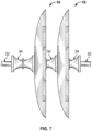
- the disc 12 or coulter 14 is connected to a mounting apparatus such as hub 24 ( FIGS. 4-6 ) on bent axle 22 or a spacer spool 34 ( FIGS. 7 and 8 ) that separate and hold in place the discs 12 along a shaft 32 which provides rotation about an axis of rotation.
- the axis of rotation is substantially horizontal.
- a spacer spool 34 is disposed on a shaft 32 between two of the discs 12 or between two of the coulters 14 and the spacer spool 34 extends radially outwardly by a distance.
- FIG. 1 is a perspective view of a concave/convex disc made in accordance with the disclosure.
- the side shown of the disc in FIG. 1 may be concave without departing from the disclosure.
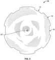
- FIG. 2 is a perspective view of a concave/convex disc.
- the side shown of the disc in FIG. 2 may be convex without departing from the scope of the appended claims.
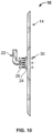
- FIG. 6 shows that the hub 24 is preferably attached to the disc 12 around a central opening 20 by placing threaded fasteners 26, such as bolts, through substantially aligned holes 28 in the hub 24, through substantially aligned holes 28 extending through the disc 12 or coulter 14 to make sure that the hub 24 is securely fastened to the disc 12. Nuts 30 are threadably attached to the ends of the threaded fasteners 26 to hold the hub 24 to the disc 12.
- FIGS. 4-6 show that the hub 24 conforms to the surface of the disc 12.
- the hub 24 shown in FIG. 10 is preferably of the same configuration as that shown in FIGS. 4-6 .
- the central opening is adapted to be attached to an agricultural implement, such as a disc harrow, disc seeder, or planter.
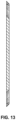
- a second embodiment of the disclosure is a coulter 14 shown in FIGS. 9-11 and 13 .
- the only difference between the coulter 14 of FIGS. 9-11 and 13 and the disc 12 of FIGS. 1-3 is that the coulter 14 is primarily flat, whereas the disc 12 may be convex on one side and concave on the other side.
Landscapes
- Life Sciences & Earth Sciences (AREA)
- Soil Sciences (AREA)
- Environmental Sciences (AREA)
- Engineering & Computer Science (AREA)
- Mechanical Engineering (AREA)
- Soil Working Implements (AREA)
- Threshing Machine Elements (AREA)
Claims (13)
- In den Boden eingreifende landwirtschaftliche Bodenbearbeitungsschar (10, 14) umfassend:eine Scheibe (12) mit einer mittigen Öffnung (20), die zur Befestigung an einem Gerät zur Drehung um eine Drehachse angepasst ist;wobei die Scheibe einen Außenumfang (18) aufweist; unddadurch gekennzeichnet, dass sie ferner umfasst:eine Vielzahl von Kerben (16) auf Stufenebene in der Scheibe von einer Stelle im Wesentlichen am Außenumfang hin zu der mittigen Öffnung;wobei jede der Vielzahl von Kerben auf Stufenebene eine Tiefe (40) und eine Breite (42) umfasst,wobei die Tiefe 50 % oder weniger als die Breite beträgt, undwobei die Kerben auf Stufenebene eine gleichmäßige Tiefe aufweisen.
- Landwirtschaftliche Bodenbearbeitungsschar nach Anspruch 1, wobei die Scheibe auf der einen Seite konvex und auf der anderen konkav ist.
- Landwirtschaftliche Bodenbearbeitungsschar nach Anspruch 1, wobei die Scheibe im Wesentlichen flach ist.
- Landwirtschaftliche Bodenbearbeitungsschar nach den Ansprüchen 1 bis 3, wobei eine Nabe (24) um die mittige Öffnung herum an der Scheibe befestigt ist.
- Landwirtschaftliche Bodenbearbeitungsschar nach den Ansprüchen 1 bis 4, wobei im Wesentlichen ausgerichtete Löcher (28) durch die Schar und durch die Nabe verlaufen und Gewindebefestigungen (26) sich durch die ausgerichteten Löcher erstrecken, um die Nabe an der Schar befestigt zu halten.
- Landwirtschaftliche Bodenbearbeitungsschar nach den Ansprüchen 1 bis 5, wobei eine Abstandshalterspule (34) auf einer Welle (32) zwischen zwei der Scheiben angeordnet ist und die Abstandshalterspule sich um einen Abstand radial nach außen erstreckt.
- In den Boden eingreifende landwirtschaftliche Bodenbearbeitungsschareinrichtung, dadurch gekennzeichnet, dass sie umfasst:
eine in den Boden eingreifende landwirtschaftliche Bodenbearbeitungsschar nach einem der Ansprüche 1 bis 3; und eine Nabe (24), die um die mittige Öffnung herum an der Scheibe angebracht ist. - Landwirtschaftliche Bodenbearbeitungsschareinrichtung nach Anspruch 7, wobei im Wesentlichen ausgerichtete Löcher (28) durch die Schar und durch die Nabe angeordnet sind und Gewindebefestigungen (26) sich durch die ausgerichteten Löcher erstrecken, um die Nabe an der Schar befestigt zu halten.
- Landwirtschaftliche Bodenbearbeitungsschareinrichtung nach den Ansprüchen 7 bis 8, die ferner mindestens zwei Scheiben umfasst.
- Landwirtschaftliche Bodenbearbeitungsschareinrichtung nach den Ansprüchen 7 bis 9, wobei eine Abstandshalterspule (34) auf einer Welle (32) zwischen zwei der Scheiben angeordnet ist und die Abstandshalterspule sich um einen Abstand radial nach außen erstreckt.
- In den Boden eingreifende landwirtschaftliche Bodenbearbeitungsschareinrichtung, dadurch gekennzeichnet, dass sie umfasst:mindestens zwei in den Boden eingreifende landwirtschaftliche Bodenbearbeitungsscharen nach einem der Ansprüche 1 bis 3; undwobei eine Abstandshalterspule (34) auf einer Welle (32) zwischen den Scheiben der mindestens zwei in den Boden eingreifenden landwirtschaftlichen Bodenbearbeitungsscharen angeordnet ist, wobei die Abstandshalterspule sich von der mittigen Öffnung jeder Scheibe radial nach außen erstreckt.
- Landwirtschaftliche Bodenbearbeitungsschareinrichtung nach den Ansprüchen 11, wobei eine Nabe (24) um die mittige Öffnung herum an der Scheibe angebracht ist.
- Landwirtschaftliche Bodenbearbeitungsschareinrichtung nach Anspruch 12, wobei im Wesentlichen ausgerichtete Löcher (28) durch jede Schreibe und durch die Nabe angeordnet sind und Gewindebefestigungen (26) sich durch die ausgerichteten Löcher erstrecken, um die Nabe an der Schar befestigt zu halten.
Priority Applications (1)
| Application Number | Priority Date | Filing Date | Title |
|---|---|---|---|
| EP24213883.2A EP4508956A3 (de) | 2019-05-22 | 2019-05-22 | Landwirtschaftliches scheibenmesser mit kerbenkante auf stufenebene |
Applications Claiming Priority (1)
| Application Number | Priority Date | Filing Date | Title |
|---|---|---|---|
| PCT/US2019/033533 WO2020236172A1 (en) | 2019-05-22 | 2019-05-22 | Agricultural disc blade with step plane notch edge |
Related Child Applications (1)
| Application Number | Title | Priority Date | Filing Date |
|---|---|---|---|
| EP24213883.2A Division EP4508956A3 (de) | 2019-05-22 | 2019-05-22 | Landwirtschaftliches scheibenmesser mit kerbenkante auf stufenebene |
Publications (3)
| Publication Number | Publication Date |
|---|---|
| EP3972403A1 EP3972403A1 (de) | 2022-03-30 |
| EP3972403A4 EP3972403A4 (de) | 2022-12-28 |
| EP3972403B1 true EP3972403B1 (de) | 2024-11-20 |
Family
ID=73458830
Family Applications (2)
| Application Number | Title | Priority Date | Filing Date |
|---|---|---|---|
| EP19929358.0A Active EP3972403B1 (de) | 2019-05-22 | 2019-05-22 | Landwirtschaftliches scheibenmesser mit kerbenkante auf stufenebene |
| EP24213883.2A Pending EP4508956A3 (de) | 2019-05-22 | 2019-05-22 | Landwirtschaftliches scheibenmesser mit kerbenkante auf stufenebene |
Family Applications After (1)
| Application Number | Title | Priority Date | Filing Date |
|---|---|---|---|
| EP24213883.2A Pending EP4508956A3 (de) | 2019-05-22 | 2019-05-22 | Landwirtschaftliches scheibenmesser mit kerbenkante auf stufenebene |
Country Status (8)
| Country | Link |
|---|---|
| US (1) | US20220210961A1 (de) |
| EP (2) | EP3972403B1 (de) |
| AU (1) | AU2019446575A1 (de) |
| CA (1) | CA3141528A1 (de) |
| ES (1) | ES3006115T3 (de) |
| MX (2) | MX2021014108A (de) |
| PL (1) | PL3972403T3 (de) |
| WO (1) | WO2020236172A1 (de) |
Family Cites Families (18)
| Publication number | Priority date | Publication date | Assignee | Title |
|---|---|---|---|---|
| US2749694A (en) * | 1952-01-02 | 1956-06-12 | Ferguson Harry Inc | Reversible heavy duty disc harrow |
| US2749649A (en) | 1952-12-30 | 1956-06-12 | Archie L Fitzsimmons | Trolling ballast |
| US4246971A (en) * | 1977-11-22 | 1981-01-27 | Ralph Mckay Limited | Tillage discs |
| US4420048A (en) * | 1981-12-10 | 1983-12-13 | Deere & Company | Disk gang assembly |
| US6425445B1 (en) * | 1996-03-28 | 2002-07-30 | Tarver, Iii Sam A. | Enhanced minimum tillage planter/renovator system |
| US6554079B2 (en) | 2001-02-14 | 2003-04-29 | Douglas G. Bruce | Earth working disc with large notches |
| US7497270B2 (en) | 2005-09-28 | 2009-03-03 | Bruce Douglas G | Variable wave coulter |
| US20210103642A9 (en) | 2005-12-14 | 2021-04-08 | Michael H. Wigler | Determining a probabilistic diagnosis of cancer by analysis of genomic copy number variations |
| US7721815B2 (en) * | 2007-04-30 | 2010-05-25 | Cnh America Llc | Cushion standard shield system |
| SE533877C2 (sv) * | 2009-05-29 | 2011-02-15 | Vaederstad Verken Ab | Tallrik för ett lantbruksredskap |
| US7878262B1 (en) | 2009-07-09 | 2011-02-01 | Douglas G Bruce | Notched coulter/disc and method of making same |
| US20110147018A1 (en) * | 2009-12-23 | 2011-06-23 | Bruce Douglas G | Tillage blade configured to stay sharp longer |
| US20110220375A1 (en) * | 2010-03-12 | 2011-09-15 | Connell Jr Richard Joseph | Shaft Alighment And Anti-Corrosion Liner For A Disk Gang |
| US9392737B2 (en) * | 2013-07-26 | 2016-07-19 | Natt Tolls Group Inc. | Wavy disc blade with notches |
| US9775274B2 (en) * | 2014-03-26 | 2017-10-03 | Deere & Company | Adjustable disk mounting assembly |
| US10390471B2 (en) | 2014-07-07 | 2019-08-27 | Douglas G. Bruce | Agricultural drill/planter/coulter/disc blade with sine wave edge |
| US10827662B2 (en) * | 2018-04-05 | 2020-11-10 | Deere & Company | Disk blade with sharpened edge and relief portion and method of manufacturing the same |
| CN109451885A (zh) | 2018-12-19 | 2019-03-12 | 常熟得美零部件有限公司 | 独立型犁刀臂组件 |
-
2019
- 2019-05-22 US US17/613,338 patent/US20220210961A1/en active Pending
- 2019-05-22 AU AU2019446575A patent/AU2019446575A1/en active Pending
- 2019-05-22 PL PL19929358.0T patent/PL3972403T3/pl unknown
- 2019-05-22 MX MX2021014108A patent/MX2021014108A/es unknown
- 2019-05-22 ES ES19929358T patent/ES3006115T3/es active Active
- 2019-05-22 CA CA3141528A patent/CA3141528A1/en active Pending
- 2019-05-22 EP EP19929358.0A patent/EP3972403B1/de active Active
- 2019-05-22 EP EP24213883.2A patent/EP4508956A3/de active Pending
- 2019-05-22 WO PCT/US2019/033533 patent/WO2020236172A1/en not_active Ceased
-
2021
- 2021-11-17 MX MX2025014239A patent/MX2025014239A/es unknown
Also Published As
| Publication number | Publication date |
|---|---|
| EP4508956A2 (de) | 2025-02-19 |
| CA3141528A1 (en) | 2020-11-26 |
| MX2025014239A (es) | 2026-01-07 |
| WO2020236172A1 (en) | 2020-11-26 |
| AU2019446575A1 (en) | 2021-12-23 |
| MX2021014108A (es) | 2022-02-11 |
| US20220210961A1 (en) | 2022-07-07 |
| EP3972403A4 (de) | 2022-12-28 |
| EP3972403A1 (de) | 2022-03-30 |
| ES3006115T3 (en) | 2025-03-17 |
| PL3972403T3 (pl) | 2025-02-24 |
| EP4508956A3 (de) | 2025-05-14 |
Similar Documents
| Publication | Publication Date | Title |
|---|---|---|
| EP3672387B1 (de) | Landwirtschaftliche bodenbearbeitungsanordnung und bauteile | |
| US8794345B2 (en) | Strip-till no build-up berm builder blade for strip-till farm implement | |
| US20110155401A1 (en) | Vertical Tine Tillage Tandem Frame And Inter-related Secondary Tillage, Planting and Fertilizing Machine | |
| US10555452B2 (en) | Row cleaner/closing wheel | |
| US12446481B2 (en) | Agricultural drill/planter/coulter/disc blade with step plane notch edge | |
| US7497270B2 (en) | Variable wave coulter | |
| CN102918945A (zh) | 变曲率轮齿式破茬松土器 | |
| EP3972403B1 (de) | Landwirtschaftliches scheibenmesser mit kerbenkante auf stufenebene | |
| EP3096597B1 (de) | Verfahren und arbeitsgerätregulierungsvorrichtung für eine landwirtschaftliche maschine | |
| RU2799085C2 (ru) | Сельскохозяйственный дисковый нож c кромкой со ступенчатыми плоскими выемками (варианты) | |
| CA2561846C (en) | Variable wave coulter | |
| RU2011104096A (ru) | Комплект универсального почвообрабатывающего сменного орудия, стоечно-корпусного микровибрационного привода с рабочими частями "викост" | |
| AU2023360034A1 (en) | Agricultural tillage implement and assemblies | |
| AU2017276303B2 (en) | A Vertical Cultivation Tool |
Legal Events
| Date | Code | Title | Description |
|---|---|---|---|
| STAA | Information on the status of an ep patent application or granted ep patent |
Free format text: STATUS: THE INTERNATIONAL PUBLICATION HAS BEEN MADE |
|
| PUAI | Public reference made under article 153(3) epc to a published international application that has entered the european phase |
Free format text: ORIGINAL CODE: 0009012 |
|
| STAA | Information on the status of an ep patent application or granted ep patent |
Free format text: STATUS: REQUEST FOR EXAMINATION WAS MADE |
|
| 17P | Request for examination filed |
Effective date: 20211116 |
|
| AK | Designated contracting states |
Kind code of ref document: A1 Designated state(s): AL AT BE BG CH CY CZ DE DK EE ES FI FR GB GR HR HU IE IS IT LI LT LU LV MC MK MT NL NO PL PT RO RS SE SI SK SM TR |
|
| DAV | Request for validation of the european patent (deleted) | ||
| DAX | Request for extension of the european patent (deleted) | ||
| A4 | Supplementary search report drawn up and despatched |
Effective date: 20221128 |
|
| RIC1 | Information provided on ipc code assigned before grant |
Ipc: A01B 21/08 20060101ALI20221123BHEP Ipc: A01B 15/16 20060101ALI20221123BHEP Ipc: A01B 7/00 20060101AFI20221123BHEP |
|
| GRAP | Despatch of communication of intention to grant a patent |
Free format text: ORIGINAL CODE: EPIDOSNIGR1 |
|
| STAA | Information on the status of an ep patent application or granted ep patent |
Free format text: STATUS: GRANT OF PATENT IS INTENDED |
|
| INTG | Intention to grant announced |
Effective date: 20240516 |
|
| GRAS | Grant fee paid |
Free format text: ORIGINAL CODE: EPIDOSNIGR3 |
|
| GRAA | (expected) grant |
Free format text: ORIGINAL CODE: 0009210 |
|
| STAA | Information on the status of an ep patent application or granted ep patent |
Free format text: STATUS: THE PATENT HAS BEEN GRANTED |
|
| AK | Designated contracting states |
Kind code of ref document: B1 Designated state(s): AL AT BE BG CH CY CZ DE DK EE ES FI FR GB GR HR HU IE IS IT LI LT LU LV MC MK MT NL NO PL PT RO RS SE SI SK SM TR |
|
| RAP1 | Party data changed (applicant data changed or rights of an application transferred) |
Owner name: OSMUNDSON MFG.CO. |
|
| REG | Reference to a national code |
Ref country code: GB Ref legal event code: FG4D |
|
| RIN1 | Information on inventor provided before grant (corrected) |
Inventor name: BRUCE, DOUGLAS, G. |
|
| REG | Reference to a national code |
Ref country code: CH Ref legal event code: EP |
|
| REG | Reference to a national code |
Ref country code: DE Ref legal event code: R096 Ref document number: 602019062433 Country of ref document: DE |
|
| REG | Reference to a national code |
Ref country code: IE Ref legal event code: FG4D |
|
| P01 | Opt-out of the competence of the unified patent court (upc) registered |
Free format text: CASE NUMBER: APP_63701/2024 Effective date: 20241201 |
|
| REG | Reference to a national code |
Ref country code: ES Ref legal event code: FG2A Ref document number: 3006115 Country of ref document: ES Kind code of ref document: T3 Effective date: 20250317 |
|
| REG | Reference to a national code |
Ref country code: LT Ref legal event code: MG9D |
|
| REG | Reference to a national code |
Ref country code: NL Ref legal event code: MP Effective date: 20241120 |
|
| PG25 | Lapsed in a contracting state [announced via postgrant information from national office to epo] |
Ref country code: PT Free format text: LAPSE BECAUSE OF FAILURE TO SUBMIT A TRANSLATION OF THE DESCRIPTION OR TO PAY THE FEE WITHIN THE PRESCRIBED TIME-LIMIT Effective date: 20250320 Ref country code: HR Free format text: LAPSE BECAUSE OF FAILURE TO SUBMIT A TRANSLATION OF THE DESCRIPTION OR TO PAY THE FEE WITHIN THE PRESCRIBED TIME-LIMIT Effective date: 20241120 Ref country code: IS Free format text: LAPSE BECAUSE OF FAILURE TO SUBMIT A TRANSLATION OF THE DESCRIPTION OR TO PAY THE FEE WITHIN THE PRESCRIBED TIME-LIMIT Effective date: 20250320 |
|
| PG25 | Lapsed in a contracting state [announced via postgrant information from national office to epo] |
Ref country code: FI Free format text: LAPSE BECAUSE OF FAILURE TO SUBMIT A TRANSLATION OF THE DESCRIPTION OR TO PAY THE FEE WITHIN THE PRESCRIBED TIME-LIMIT Effective date: 20241120 Ref country code: NL Free format text: LAPSE BECAUSE OF FAILURE TO SUBMIT A TRANSLATION OF THE DESCRIPTION OR TO PAY THE FEE WITHIN THE PRESCRIBED TIME-LIMIT Effective date: 20241120 |
|
| REG | Reference to a national code |
Ref country code: AT Ref legal event code: MK05 Ref document number: 1742655 Country of ref document: AT Kind code of ref document: T Effective date: 20241120 |
|
| PG25 | Lapsed in a contracting state [announced via postgrant information from national office to epo] |
Ref country code: BG Free format text: LAPSE BECAUSE OF FAILURE TO SUBMIT A TRANSLATION OF THE DESCRIPTION OR TO PAY THE FEE WITHIN THE PRESCRIBED TIME-LIMIT Effective date: 20241120 |
|
| PG25 | Lapsed in a contracting state [announced via postgrant information from national office to epo] |
Ref country code: NO Free format text: LAPSE BECAUSE OF FAILURE TO SUBMIT A TRANSLATION OF THE DESCRIPTION OR TO PAY THE FEE WITHIN THE PRESCRIBED TIME-LIMIT Effective date: 20250220 |
|
| PG25 | Lapsed in a contracting state [announced via postgrant information from national office to epo] |
Ref country code: AT Free format text: LAPSE BECAUSE OF FAILURE TO SUBMIT A TRANSLATION OF THE DESCRIPTION OR TO PAY THE FEE WITHIN THE PRESCRIBED TIME-LIMIT Effective date: 20241120 Ref country code: GR Free format text: LAPSE BECAUSE OF FAILURE TO SUBMIT A TRANSLATION OF THE DESCRIPTION OR TO PAY THE FEE WITHIN THE PRESCRIBED TIME-LIMIT Effective date: 20250221 Ref country code: LV Free format text: LAPSE BECAUSE OF FAILURE TO SUBMIT A TRANSLATION OF THE DESCRIPTION OR TO PAY THE FEE WITHIN THE PRESCRIBED TIME-LIMIT Effective date: 20241120 |
|
| PG25 | Lapsed in a contracting state [announced via postgrant information from national office to epo] |
Ref country code: RS Free format text: LAPSE BECAUSE OF FAILURE TO SUBMIT A TRANSLATION OF THE DESCRIPTION OR TO PAY THE FEE WITHIN THE PRESCRIBED TIME-LIMIT Effective date: 20250220 |
|
| PG25 | Lapsed in a contracting state [announced via postgrant information from national office to epo] |
Ref country code: SM Free format text: LAPSE BECAUSE OF FAILURE TO SUBMIT A TRANSLATION OF THE DESCRIPTION OR TO PAY THE FEE WITHIN THE PRESCRIBED TIME-LIMIT Effective date: 20241120 |
|
| PGFP | Annual fee paid to national office [announced via postgrant information from national office to epo] |
Ref country code: PL Payment date: 20250526 Year of fee payment: 7 Ref country code: DE Payment date: 20250528 Year of fee payment: 7 |
|
| PG25 | Lapsed in a contracting state [announced via postgrant information from national office to epo] |
Ref country code: DK Free format text: LAPSE BECAUSE OF FAILURE TO SUBMIT A TRANSLATION OF THE DESCRIPTION OR TO PAY THE FEE WITHIN THE PRESCRIBED TIME-LIMIT Effective date: 20241120 |
|
| PGFP | Annual fee paid to national office [announced via postgrant information from national office to epo] |
Ref country code: GB Payment date: 20250522 Year of fee payment: 7 Ref country code: ES Payment date: 20250605 Year of fee payment: 7 |
|
| PGFP | Annual fee paid to national office [announced via postgrant information from national office to epo] |
Ref country code: IT Payment date: 20250528 Year of fee payment: 7 |
|
| PG25 | Lapsed in a contracting state [announced via postgrant information from national office to epo] |
Ref country code: EE Free format text: LAPSE BECAUSE OF FAILURE TO SUBMIT A TRANSLATION OF THE DESCRIPTION OR TO PAY THE FEE WITHIN THE PRESCRIBED TIME-LIMIT Effective date: 20241120 |
|
| PGFP | Annual fee paid to national office [announced via postgrant information from national office to epo] |
Ref country code: FR Payment date: 20250523 Year of fee payment: 7 |
|
| PG25 | Lapsed in a contracting state [announced via postgrant information from national office to epo] |
Ref country code: RO Free format text: LAPSE BECAUSE OF FAILURE TO SUBMIT A TRANSLATION OF THE DESCRIPTION OR TO PAY THE FEE WITHIN THE PRESCRIBED TIME-LIMIT Effective date: 20241120 |
|
| PG25 | Lapsed in a contracting state [announced via postgrant information from national office to epo] |
Ref country code: SK Free format text: LAPSE BECAUSE OF FAILURE TO SUBMIT A TRANSLATION OF THE DESCRIPTION OR TO PAY THE FEE WITHIN THE PRESCRIBED TIME-LIMIT Effective date: 20241120 |
|
| PGFP | Annual fee paid to national office [announced via postgrant information from national office to epo] |
Ref country code: CZ Payment date: 20250521 Year of fee payment: 7 |
|
| REG | Reference to a national code |
Ref country code: DE Ref legal event code: R097 Ref document number: 602019062433 Country of ref document: DE |
|
| PG25 | Lapsed in a contracting state [announced via postgrant information from national office to epo] |
Ref country code: SE Free format text: LAPSE BECAUSE OF FAILURE TO SUBMIT A TRANSLATION OF THE DESCRIPTION OR TO PAY THE FEE WITHIN THE PRESCRIBED TIME-LIMIT Effective date: 20241120 |
|
| PLBE | No opposition filed within time limit |
Free format text: ORIGINAL CODE: 0009261 |
|
| STAA | Information on the status of an ep patent application or granted ep patent |
Free format text: STATUS: NO OPPOSITION FILED WITHIN TIME LIMIT |
|
| 26N | No opposition filed |
Effective date: 20250821 |
|
| REG | Reference to a national code |
Ref country code: CH Ref legal event code: H13 Free format text: ST27 STATUS EVENT CODE: U-0-0-H10-H13 (AS PROVIDED BY THE NATIONAL OFFICE) Effective date: 20251223 |
|
| PG25 | Lapsed in a contracting state [announced via postgrant information from national office to epo] |
Ref country code: LU Free format text: LAPSE BECAUSE OF NON-PAYMENT OF DUE FEES Effective date: 20250522 |
|
| PG25 | Lapsed in a contracting state [announced via postgrant information from national office to epo] |
Ref country code: CH Free format text: LAPSE BECAUSE OF NON-PAYMENT OF DUE FEES Effective date: 20250531 |
|
| PG25 | Lapsed in a contracting state [announced via postgrant information from national office to epo] |
Ref country code: MC Free format text: LAPSE BECAUSE OF FAILURE TO SUBMIT A TRANSLATION OF THE DESCRIPTION OR TO PAY THE FEE WITHIN THE PRESCRIBED TIME-LIMIT Effective date: 20241120 |