EP3972377A2 - Method and system for user information management - Google Patents
Method and system for user information management Download PDFInfo
- Publication number
- EP3972377A2 EP3972377A2 EP21197984.4A EP21197984A EP3972377A2 EP 3972377 A2 EP3972377 A2 EP 3972377A2 EP 21197984 A EP21197984 A EP 21197984A EP 3972377 A2 EP3972377 A2 EP 3972377A2
- Authority
- EP
- European Patent Office
- Prior art keywords
- network element
- allocated
- radio bearer
- bearer context
- uniquely identify
- Prior art date
- Legal status (The legal status is an assumption and is not a legal conclusion. Google has not performed a legal analysis and makes no representation as to the accuracy of the status listed.)
- Granted
Links
- 238000000034 method Methods 0.000 title claims abstract description 86
- 230000004044 response Effects 0.000 claims abstract description 51
- 230000011664 signaling Effects 0.000 claims abstract description 16
- 238000004891 communication Methods 0.000 claims description 7
- 238000012217 deletion Methods 0.000 claims description 3
- 230000037430 deletion Effects 0.000 claims description 3
- 230000005540 biological transmission Effects 0.000 abstract description 114
- 238000012986 modification Methods 0.000 abstract description 17
- 230000004048 modification Effects 0.000 abstract description 17
- 238000007726 management method Methods 0.000 description 40
- 230000006870 function Effects 0.000 description 20
- CSRZQMIRAZTJOY-UHFFFAOYSA-N trimethylsilyl iodide Substances C[Si](C)(C)I CSRZQMIRAZTJOY-UHFFFAOYSA-N 0.000 description 18
- 238000010586 diagram Methods 0.000 description 4
- 101001055444 Homo sapiens Mediator of RNA polymerase II transcription subunit 20 Proteins 0.000 description 1
- 102100026165 Mediator of RNA polymerase II transcription subunit 20 Human genes 0.000 description 1
- 108091005487 SCARB1 Proteins 0.000 description 1
- 102100037118 Scavenger receptor class B member 1 Human genes 0.000 description 1
- 230000009977 dual effect Effects 0.000 description 1
- 230000007774 longterm Effects 0.000 description 1
- 238000010295 mobile communication Methods 0.000 description 1
- 238000012545 processing Methods 0.000 description 1
- 230000001960 triggered effect Effects 0.000 description 1
- 230000005641 tunneling Effects 0.000 description 1
Images


Classifications
-
- H—ELECTRICITY
- H04—ELECTRIC COMMUNICATION TECHNIQUE
- H04W—WIRELESS COMMUNICATION NETWORKS
- H04W72/00—Local resource management
- H04W72/04—Wireless resource allocation
- H04W72/044—Wireless resource allocation based on the type of the allocated resource
- H04W72/0453—Resources in frequency domain, e.g. a carrier in FDMA
-
- H—ELECTRICITY
- H04—ELECTRIC COMMUNICATION TECHNIQUE
- H04W—WIRELESS COMMUNICATION NETWORKS
- H04W76/00—Connection management
- H04W76/10—Connection setup
-
- H—ELECTRICITY
- H04—ELECTRIC COMMUNICATION TECHNIQUE
- H04W—WIRELESS COMMUNICATION NETWORKS
- H04W76/00—Connection management
- H04W76/10—Connection setup
- H04W76/11—Allocation or use of connection identifiers
-
- H—ELECTRICITY
- H04—ELECTRIC COMMUNICATION TECHNIQUE
- H04W—WIRELESS COMMUNICATION NETWORKS
- H04W76/00—Connection management
- H04W76/10—Connection setup
- H04W76/12—Setup of transport tunnels
-
- H—ELECTRICITY
- H04—ELECTRIC COMMUNICATION TECHNIQUE
- H04W—WIRELESS COMMUNICATION NETWORKS
- H04W76/00—Connection management
- H04W76/10—Connection setup
- H04W76/18—Management of setup rejection or failure
-
- H—ELECTRICITY
- H04—ELECTRIC COMMUNICATION TECHNIQUE
- H04W—WIRELESS COMMUNICATION NETWORKS
- H04W8/00—Network data management
- H04W8/22—Processing or transfer of terminal data, e.g. status or physical capabilities
-
- H—ELECTRICITY
- H04—ELECTRIC COMMUNICATION TECHNIQUE
- H04W—WIRELESS COMMUNICATION NETWORKS
- H04W8/00—Network data management
- H04W8/26—Network addressing or numbering for mobility support
-
- H—ELECTRICITY
- H04—ELECTRIC COMMUNICATION TECHNIQUE
- H04W—WIRELESS COMMUNICATION NETWORKS
- H04W80/00—Wireless network protocols or protocol adaptations to wireless operation
- H04W80/08—Upper layer protocols
- H04W80/10—Upper layer protocols adapted for application session management, e.g. SIP [Session Initiation Protocol]
-
- H—ELECTRICITY
- H04—ELECTRIC COMMUNICATION TECHNIQUE
- H04W—WIRELESS COMMUNICATION NETWORKS
- H04W88/00—Devices specially adapted for wireless communication networks, e.g. terminals, base stations or access point devices
- H04W88/08—Access point devices
- H04W88/085—Access point devices with remote components
-
- H—ELECTRICITY
- H04—ELECTRIC COMMUNICATION TECHNIQUE
- H04W—WIRELESS COMMUNICATION NETWORKS
- H04W88/00—Devices specially adapted for wireless communication networks, e.g. terminals, base stations or access point devices
- H04W88/02—Terminal devices
-
- H—ELECTRICITY
- H04—ELECTRIC COMMUNICATION TECHNIQUE
- H04W—WIRELESS COMMUNICATION NETWORKS
- H04W88/00—Devices specially adapted for wireless communication networks, e.g. terminals, base stations or access point devices
- H04W88/08—Access point devices
Definitions
- the disclosure relates to the technical field of wireless communication systems, for example, to a method and system for user information management.
- a fronthaul interface i.e., common public radio interface (CPRI)
- BBU baseband processing unit
- RRU radio remote unit
- I in-phase
- Q quadrature
- a method of user information management that includes:
- a system for user information management includes: a first network element and a second network element, wherein a fronthaul interface exists between the first network element and the second network element;
- a system for user information management includes:
- a computer readable storage medium stores computer readable instructions, which are configured to perform the methods as described above.
- the air interface rate in the 5G system is increased to tens of giga bits per second (Gbps), the traffic demand of the CPRI interface will rise to an order of tera bits per second (Tbps).
- Gbps giga bits per second
- Tbps tera bits per second
- the increase in traffic demand brings tremendous pressure on the network deployment cost and deployment difficulty. Therefore, in the 5G system, it is necessary to redefine the division mode of the fronthaul interface.
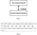
- the division mode of the fronthaul interface consideration is made in terms of transmission capacity, transmission delay, and convenience of deployment. For example, considering non-ideal fronthaul transmission, a network function that is not sensitive to delay is placed in the first network element (for example, a Centralized Unit (CU)), a delay-sensitive network function is placed in a second network element (such as a distributed unit (DU)).
- CU Centralized Unit
- DU distributed unit
- Data between the first network element and the second network element is transmitted through at least one of an ideal fronthaul and a non-ideal fronthaul.
- the transmission interface is referred to as a fronthaul interface, and the fronthaul interface between the first network element and the second network element is shown in FIG. 1 .
- the first protocol entity includes radio resource control (RRC), the second protocol entity includes packet data convergence protocol (PDCP), the third protocol entity includes radio link control (RLC), and the fourth protocol entity includes media access control (MAC), a physical layer, and a radio frequency unit.
- RRC radio resource control
- PDCP packet data convergence protocol
- RLC radio link control
- MAC media access control
- the first network element and the second network element include different protocol entities, for example, the first network element includes a first protocol entity and a second protocol entity, and the second network element includes other protocol entities as described above.
- the first network element communicates with the second network element through the fronthaul interface.
- the method and system for managing user information provided by the following embodiments can implement user information management on a fronthaul interface between the first network element and the second network element.
- the first network element and the second network element exchange information through the fronthaul interface.
- the fronthaul is an ideal fronthaul.
- the fronthaul is a non-ideal fronthaul.
- the transmission delay of the ideal fronthaul is relatively small, for example, dozens of microseconds to hundreds of microseconds, and the transmission delay of the non-ideal fronthaul is relatively large, for example, in an order of milliseconds.
- the first network element and the second network element have different functional divisions.
- the first network element is a CU and the second network element is a DU, the CU and the DU are separated from each other, and functions included in the CU and functions included in the DU are shown in FIG. 2 .
- RRC and PDCP are separated from each other, similar to the 1A structure in Dual Connectivity (DC). That is, RRC is located in the CU, and PDCP, RLC, Ethernet MAC, physical layer (PHY), and radio frequency (RF) and other functions are located in the DU. That is, the entire user plane (UP) is located in the DU.
- DC Dual Connectivity
- PDCP and RLC are separated from each other, similar to the 3C structure in DC. That is, RRC and PDCP are located within the CU, and RLC, MAC, PHY, and RF functions are located in the DU.
- a high layer of RLC is separated from a low layer of RLC.
- the lower layer of RLC (partial function of RLC), MAC, PHY, and RF part are located in the DU, and RRC, PDCP, and the upper layer of RLC (partial functions of RLC) functions are located in the CU.
- RLC and MAC are separated from each other, MAC, PHY, and RF are located in the DU, and RRC, PDCP, and RLC functions are located in the CU.
- MAC In Option 5, internal functions of MAC are separated. Some MAC functions (such as Hybrid Automatic Repeat ReQuest (HARQ)), PHY, and RF are located in the DU. The other upper layer functions in FIG. 2 are located in the CU.
- HARQ Hybrid Automatic Repeat ReQuest
- MAC and PHY are separated from each other, MAC, PHY, and RF are located in the DU, and RRC, PDCP, and RLC functions are located in the CU.
- PHY and RF are separated, the RF function is located in the DU, and other upper layer functions are located in the CU.
- user information includes UE radio bearer context.
- the process of implementing the user information management will be illustrated in detail from the following aspects: a process of establishing user context information at the second network element through a UE radio bearer context establishing process between the first network element (CU) and the second network element (DU), a process of reconfiguring user context information at the second network element through a UE radio bearer context reconfiguration process, and a process of deleting user context information at the second network element through a UE radio bearer context release process.
- the user context information includes UE radio bearer information.
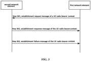
- An embodiment provides a method for user information management. As shown in FIG. 3 , the method includes the following steps.
- step 301 the first network element transmits a setup request message of the UE radio bearer context to the second network element.
- the setup request message includes one or more of the following information: a first UE association flag, configuration information about signaling radio bearers (SRBs), and information about SRB transmission channel uplink address (e.g., address of the first network element).
- SRBs signaling radio bearers
- the first UE association flag includes: an application-layer protocol (AP) identifier (ID) allocated by the first network element to uniquely identify the UE, or a temporary mobile subscriber identity (S-TMSI), or a unique ID for identifying UE by a radio access network.
- AP application-layer protocol
- S-TMSI temporary mobile subscriber identity
- configuration information about the SRBs is configuration information of SRB1 (for example, used for RRC signaling transmission through the air interface) and SRB2 (for example, used for measuring signaling) allocated by the first network element.
- the SRB is transmitted by using the stream control transmission protocol (SCTP).
- SCTP stream control transmission protocol
- the SRB is transmitted by using a user plane general packet radio service (GPRS) tunneling protocol-user (GTP-U), and similar to data radio bearer (DRB) transmission
- the second network element allocates a GPT-U address to the SRB
- the GPT-U address includes a transport network layer (TNL) address and a tunnel endpoint identifier (TE ID).
- TNL transport network layer
- TE ID tunnel endpoint identifier
- the first network element determines that information of the UE radio bearer context is established by the second network element.
- the setup response message includes one or more of the following information: a second UE association flag, configuration information about the SRBs, information about SRB transmission channel downlink address (e.g., second network element address), and a cause value.
- the second UE association flag includes: an interface AP ID that is allocated by the first network element to uniquely identify the UE, and an interface AP ID that is allocated by the second network element to uniquely identify the UE; or S-TMSI; or RAN UE ID.
- configuration information about the SRBs includes configuration information about the SRBs that are set up by the second network element or configuration information about the modified SRBs.
- the configuration information about the modified SRBs is the SRB configuration information after the DU modifies the SRB configuration according to resource occupation.
- the cause value is a cause for which the second network element modifies the configuration.
- step 302 after the first network element transmits the setup request message of the UE radio bearer context to the second network element, the second network element feeds back a setup failure message of the UE radio bearer context to the first network element when failing to establish information of the UE radio bearer context.
- the first network element receives the setup failure message of the UE radio bearer context fed back by the second network element, the first network element determines that the second network element fails to establish the information of the UE radio bearer context.
- the setup failure message includes one or more of the following information: the second UE association flag and a cause of failure.
- the second UE association flag includes an interface AP ID that is allocated by the first network element CU to uniquely identify the UE, and an interface AP ID that is uniquely allocated by the second network element to the UE.
- the second UE association flag includes an S-TMSI.
- the second UE association flag includes a RAN UE ID.
- the first network element and the second network element can establish user context information at the second network element, so as to implement user information management on the fronthaul interface between the network elements.
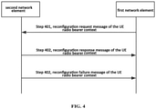
- An embodiment provides a method for managing user information. After the method for establishing information of the UE radio bearer context, the method further includes a process for modifying the UE radio bearer context. As shown in FIG. 4 , the reconfiguration process includes the following steps.
- the first network element transmits a reconfiguration request message of the UE radio bearer context to the second network element, upon determining that information of the UE radio bearer context is required to be reconfigured at the second network element.
- the reconfiguration request message includes one or more of the following information: a second UE association flag, configuration information about data radio bearers (DRBs), information about DRB transmission channel uplink address, configuration information about the modified SRBs, or UE capability coordination information.
- DRBs data radio bearers
- the second UE association flag includes an interface AP ID that is allocated by the first network element to uniquely identify the UE, and an interface AP ID that is allocated by the second network element to uniquely identify the UE.
- the second UE association flag includes an S-TMSI.
- the second UE association flag includes a RAN UE ID.
- configuration information about the DRBs is configuration information related to one or more DRBs allocated by the first network element.
- the information about DRB transmission channel uplink address is in one of the following forms: transmission channel uplink address of each UE, transmission channel uplink address of each PDU session (SESSION), transmission channel uplink address of each service flow (FLOW), or transmission channel uplink address of each DRB.
- the information about DRB transmission channel uplink address is in one of the following forms: UE-based transmission channel uplink address, PDU-SESSION-based transmission channel uplink address, service-flow-based transmission channel uplink address, or DRB-based transmission channel uplink address.
- the PDU-SESSION-based transmission channel uplink address is DRB transmission channel uplink address established by the UE.
- the PDU-SESSION-based transmission channel uplink address is transmission channel uplink address of one of the one or more PDU sessions that are currently supported by the UE.
- the service-flow-based transmission channel uplink address is transmission channel uplink address of at least one service flow that is being processed by the UE.
- the DRB-based transmission channel uplink address is transmission channel uplink address of one or more DRBs that the UE is to establish or modify.
- the allocated channel being closer to the upper layer results in more information that can be exchanged between the first network element and the second network element.
- the reconfiguration request message includes transmission channel uplink address of each DRB or transmission channel uplink address of each UE.
- the PDU process level can be considered.
- the UE capability coordination information is information about how to allocate UE capabilities among multiple second network elements in a multi-connection scenario. In an embodiment, UE capability coordination is re-executed when there are multiple PDU sessions.
- the first network element determines, after receiving the reconfiguration response message of the UE radio bearer context fed back by the second network element, that the second network element completes the reconfiguration of information of the UE radio bearer context; wherein the reconfiguration response message includes one or more of the following information: a second UE association flag, configuration information about DRBs, information about DRB transmission channel downlink address, configuration information about the modified SRBs, and UE capability coordination information.
- the second UE association flag includes an interface AP ID that is allocated by the first network element to uniquely identify the UE, and an interface AP ID that is uniquely allocated for the UE by the second network element; or S-TMSI; or RAN UE ID.
- configuration information about the DRBs includes a list of DRBs set up by the second network element or a list of modified DRBs.
- the second network element accepts or rejects one or more DRBs according to resource conditions.
- the information about DRB transmission channel downlink address is in one of the following forms: transmission channel downlink address of each UE, transmission channel downlink address of each protocol data unit PDU session (SESSION), transmission channel downlink address of each service flow, or transmission channel downlink address of each DRB.
- step 402 after the first network element transmits the reconfiguration request message of the UE radio bearer context, if the second network element fails in the reconfiguration, the second network element feeds back the reconfiguration failure message of the UE radio bearer context to the first network element.
- the first network element determines that the second network element fails to reconfigure information of the UE radio bearer context.
- the reconfiguration failure message includes the following one or more of the information: a second UE association flag and a cause of the failure.
- the second UE association flag is: the interface AP ID allocated by the first network element to uniquely identify the UE and an interface AP ID allocated by the second network element to uniquely identify the UE, or the S-TMSI, or the RAN UE ID.
- the first network element and the second network element can implement reconfiguration of user context information at the second network element, so as to implement user information management on the fronthaul interface between the network elements.
- An embodiment provides a method for user information management, after establishing the information of the UE radio bearer context, the method further includes a process of releasing the UE radio bearer context. As shown in FIG. 5 , the release process includes the following steps.
- step 501 upon determining that the information of the UE radio bearer context at the second network element is required to be released, the first network element transmits a release command message of the UE radio bearer context to the second network element.
- the release command message includes at least one of the following information: the second UE association flag and a cause of failure.
- the second UE association flag includes: the interface AP ID allocated by the first network element to uniquely identify the UE and an interface AP ID allocated by the second network element to uniquely identify the UE, or the S-TMSI, or the RAN UE ID.
- step 502 upon reception of a release completion message of the UE radio bearer context from the second network element, the first network element determines that the information of UE radio bearer context at the second network element is released.
- the release completion message includes the second UE association flag.
- the second UE association flag includes an interface AP ID allocated by the first network element to uniquely identify the UE and an interface AP ID allocated by the second network element to uniquely identify the UE; or S-TMSI; or RAN UE ID.
- the first network element and the second network element can delete the user context information at the second network element, so as to implement user information management on the fronthaul interface between the network elements.
- An embodiment provides a method for managing user information.
- the process of managing user information is described in conjunction with an application scenario.
- the first network element is a CU
- the second network element is a DU.
- the method includes the following steps.
- step 601 the CU receives an RRC connection request message of a UE, with which the UE requests to access a RAN.
- step 602 the CU and the DU complete the process of establishing information of the UE radio bearer context at the DU according to the foregoing embodiment.
- step 603 the CU transmits an RRC connection setup message to the UE.
- step 604 after completing the RRC connection setup, the UE returns an RRC connection setup complete message to complete the RRC connection setup of the UE.
- step 605 the CU transmits an initial UE message to 5G core network (NextGen Core, NGC).
- NGC NextGen Core
- step 606 the NGC transmits an initial context setup request message to the CU.
- step 607 upon reception of the initial context setup request message of the UE, the CU completes the process of reconfiguring the UE radio bearer context at the DU as described in the foregoing embodiment according to the carried PDU session (SESSION) information.
- SESSION carried PDU session
- the process of the CU's reconfiguring the UE radio bearer context for DU triggered by the PDU session setup process is the same as the above process.
- step 608 the CU transmits an RRC Connection Reconfiguration message to the UE.
- step 609 after completing the RRC connection reconfiguration, the UE returns an RRC connection reconfiguration complete message to the CU.
- step 610 the CU transmits an initial context setup response message to the NGC, and the process ends.
- the method in the embodiment shown in FIG. 6 can implement user information management on the fronthaul interface between the CU and the DU, and enable user access and management in an architecture in which the first network element and the second network element are separated from each other.
- An embodiment provides a method for managing user information management. This embodiment describes a PDU session modification process in conjunction with an application scenario. As shown in FIG. 7 , the method includes the following steps.
- step 701 the NGC transmits a PDU Session modification request message to the CU.
- step 702 upon reception of the PDU session modification request message, the CU completes the modification of information of the UE radio bearer context at the DU according to the carried PDU session information.
- step 703 the DU feeds back a modification response message of the radio bearer context of the UE to the CU when the modification succeeds.
- step 704 the CU transmits an RRC connection reconfiguration message to the UE.
- step 705 after completing the connection reconfiguration, the UE returns an RRC connection reconfiguration complete message to the CU.
- step 706 the CU transmits a PDU session modification complete message to the NGC, and the process ends.
- An embodiment provides a method for user information management. This embodiment describes a user context release process in conjunction with an application scenario. As shown in FIG. 8 , the method includes the following steps.
- step 801 the NGC transmits a UE context release request message (UE context release command) to the CU.
- UE context release command UE context release command
- step 802 after receiving the UE context release request message, the CU transmits an RRC connection release message to the UE.
- step 803 after completing the RRC connection release, the UE transmits an RRC connection release complete message to the CU through the DU.
- step 804 the CU completes the release of the UE radio bearer context at the DU as described in the foregoing embodiment according to the carried user information.
- step 805 the DU transmits a UE radio bearer context release complete message to the CU.
- step 806 the CU transmits a UE context deletion complete message to the NGC, and the process ends.
- the UE supports merely one PDU session.
- the CU may also trigger the UE radio bearer context release process between the CU and the DU.
- the CU if the UE supports multiple PDU sessions, the CU does not trigger the UE radio bearer context release process between the CU and the DU when receiving the PDU session release process, and reuses the UE radio bearer context reconfiguration process.
- user information management on the fronthaul interface between the CU and the DU can be implemented, enabling user access and management in an architecture in which the first network element and the second network element are separated from each other.
- An embodiment provides a system for user information management.
- the system for user information management includes: a first network element 910 and a second network element 920.
- a fronthaul interface exists between the first network element 910 and the second network element 920.
- the first network element 910 includes: a context setup request module 911.
- the context setup request module 911 is configured to transmit a setup request message of a user equipment (UE) radio bearer context to the second network element, and determine that information of the UE radio bearer context is established at the second network element upon reception of a setup response message of the UE radio bearer context fed back by the second network element; wherein the setup request message includes one or more of the following information: a first UE association flag, configuration information about signaling radio bearers (SRBs), and information about SRB transmission channel uplink address.
- UE user equipment
- the second network element 920 includes: a context setup module 921.
- the context setup module 921 is configured to locally establish information of the UE radio bearer context upon reception of the setup request message of UE radio bearer context from the first network element, and feed back a setup response message of the UE radio bearer context to the first network element when the setup succeeds; wherein the setup response message includes one or more of the following information: configuration information about SRBs set up by the second network element, configuration information about the modified SRBs, a second UE association flag, information about SRB transmission channel downlink address, and a cause value for configuration modification.
- the context setup module 921 is further configured to feed back a setup failure message of the UE radio bearer context to the first network element when failing to establish the information of the UE radio bearer context, wherein the setup failure message includes one or more of the following information: the second UE association flag and a cause of failure.
- the first network element 910 further includes a context reconfiguration request module 912
- the second network element 920 further includes a context reconfiguration module 922.
- the context reconfiguration request module 912 is configured to transmit a reconfiguration request message of the UE radio bearer context to the second network element upon determining that the information of the UE radio bearer context at the second network element is required to be reconfigured, and determine that the second network element completes reconfiguration of the information of the UE radio bearer context upon reception of a reconfiguration response message of the UE radio bearer context fed back by the second network element, wherein the reconfiguration request message includes one or more of the following information: the first UE association flag, configuration information about data radio bearers (DRBs), information about DRB transmission channel uplink address, configuration information about the modified SRBs, and UE capability coordination information.
- DRBs data radio bearers
- the context reconfiguration module 922 is configured to reconfigure the established information of the UE radio bearer context upon reception of the reconfiguration request message of the UE radio bearer context from the first network element, and feed back a reconfiguration response message of the UE radio bearer context to the first network element when the reconfiguration succeeds; wherein the configuration response message includes one or more of the following information: configuration information about the DRBs set up by the second network element, configuration information about the modified DRBs, the second UE association flag, information about DRB transmission channel downlink address, configuration information about the modified SRBs, and UE capability coordination information.
- the information about DRB transmission channel uplink address includes: transmission channel uplink address of each UE, transmission channel uplink address of each protocol data unit (PDU) session, transmission channel uplink address of each service flow, or DRB transmission channel uplink address of each DRB.
- PDU protocol data unit
- the information about DRB transmission channel downlink address includes: transmission channel downlink address of each UE, transmission channel downlink address of each protocol data unit (PDU) session, transmission channel downlink address of each service flow, or DRB transmission channel downlink address of each DRB.
- PDU protocol data unit
- the context reconfiguration module 922 is further configured to feed back a reconfiguration failure message of the UE radio bearer context to the first network element when the reconfiguration fails, wherein the reconfiguration failure message includes at least one of the following information: the second UE association flag and a cause of failure.
- the first network element 910 further includes a context release request module 913
- the second network element 920 further includes a context release module 923.
- the context release request module 913 is configured to transmit a release command message of the UE radio bearer context to the second network element upon determining that the information of the UE radio bearer context at the second network element is required to be released, wherein the release command message includes at least one of the following information: the first UE association flag and a cause of release.
- the context release module 923 is configured to perform context release upon reception of the release command message of the UE radio bearer context, and feed back a release completion message of the UE radio bearer context to the first network element; wherein the release completion message includes the second UE association flag.
- the first UE association flag (the UE association flag included in the message transmitted by the first network element 910 to the second network element 920) includes: an application-layer protocol (AP) identifier (ID) allocated by the first network element to uniquely identify the UE, or a temporary mobile subscriber identity (S-TMSI), or a residential access network (RAN) UE ID.
- AP application-layer protocol
- S-TMSI temporary mobile subscriber identity
- RAN residential access network
- the second UE association flag (the UE association flag included in the message that the second network element 920 feeds back to the first network element 910) includes: an interface AP ID allocated by the first network element to uniquely identify the UE and an interface AP ID allocated by the second network element to uniquely identify the UE, or the S-TMSI, or the RAN UE ID.
- user information management on the fronthaul interface between the CU and the DU can be implemented, enabling user access and management in an architecture in which the first network element and the second network element are separated from each other.
- An embodiment provides a system for managing user information, as shown in FIG. 10 .
- the system includes a first network element 1010 and a second network element 1020.
- the first network element 1010 includes a first memory 1011 and a first processor 1012.
- the first memory 1011 has computer instructions stored therein, and the first processor 1012 executes the computer instructions to implement the following method.
- a setup request message of the UE radio bearer context is transmitted to the second network element 1020.
- the setup request message includes one or more of the following information: a first UE association flag, configuration information about signaling radio bearers (SRBs) and information about SRB transmission channel uplink address.
- SRBs signaling radio bearers
- the second network element 1020 includes a second memory 1021 and a second processor 1022.
- the second memory 1021 has computer instructions stored therein, and the second processor 1022 executes the computer instructions to implement the following method: upon reception of the setup request message of UE radio bearer context from the first network element 1010, information of the UE radio bearer context is locally established. When the setup succeeds, a setup response message of the UE radio bearer context feeds back to the first network element 1010.
- the setup response message includes one or more of the following information: configuration information about SRBs set up by the second network element, configuration information about the modified SRBs, a second UE association flag, information about SRB transmission channel downlink address, and a cause value for configuration modification.
- the second processor 1022 is further configured to feed back a setup failure message of the UE radio bearer context to the first network element 1010 when failing to establish the information of the UE radio bearer context, wherein the setup failure message includes at least one of the following information: the second UE association flag and a cause of failure.
- the first processor 1012 is further configured to transmit a reconfiguration request message of the UE radio bearer context to the second network element 1020 upon determining that the information of the UE radio bearer context at the second network element 1020 is required to be reconfigured, the reconfiguration request message includes at least one of the following information: the first UE association flag, configuration information about data radio bearer (DRBs), information about DRB transmission channel uplink address, configuration information about the modified SRBs, or UE capability coordination information.
- DRBs data radio bearer
- the second processor 1022 is configured to reconfigure the established information of the UE radio bearer context upon reception of the reconfiguration request message of the UE radio bearer context, and feed back a reconfiguration response message of the UE radio bearer context to the first network element 1010 when the reconfiguration succeeds; wherein the configuration response message includes at least one of the following information: configuration information about the DRBs set up by the second network element 1020, configuration information about the modified DRBs, the second UE association flag, information about DRB transmission channel downlink address, configuration information about the modified SRBs, and UE capability coordination information.
- the information about DRB transmission channel uplink or downlink address includes: transmission channel uplink or downlink address of each UE, transmission channel uplink or downlink address of each protocol data unit (PDU) session, transmission channel uplink or downlink address of each service flow, or DRB transmission channel uplink or downlink address of each DRB.
- PDU protocol data unit
- the second processor 1022 is further configured to feed back a reconfiguration failure message of the UE radio bearer context to the first network element 1010 when the reconfiguration fails, the reconfiguration failure message includes at least one of the following information: the second UE association flag and a cause of failure.
- the first processor 1012 is further configured to transmit a release command message of the UE radio bearer context to the second network element 1020 upon determining that the information of the UE radio bearer context at the second network element 1020 is required to be released, the release command message includes at least one of the following information: the first UE association flag and a cause of release.
- the second processor 1022 is further configured to perform context release upon reception of the release command message of the UE radio bearer context, and feed back a release completion message of the UE radio bearer context to the first network element 1010, the release completion message includes the second UE association flag.
- the message transmitted to the second processor 1022 by the first processor 1012 includes a UE association flag (i.e., first UE association flag), which includes an application-layer protocol (AP) identifier (ID) allocated by the first network element to uniquely identify the UE, or a temporary mobile subscriber identity (S-TMSI), or a radio access network (RAN) UE ID.
- the message fed back to the first processor 1012 by the second processor 1022 includes a UE association flag (i.e., second UE association flag), which includes: the interface AP ID allocated by the first network element to uniquely identify the UE and an interface AP ID allocated by the second network element to uniquely identify the UE, or the S-TMSI, or the RAN UE ID.
- the user information management system provided in the foregoing embodiments can implement user information management on the fronthaul interface between the first network element and the second network element, and enable user access and management in an architecture in which the first network element and the second network element are separated from each other.
- all or part of steps of the various methods in the above embodiments may be implemented by instructing related hardware using a program
- the program may be stored in a computer readable storage medium, which may include a Read-Only Memory (ROM), a Random Access Memory (RAM), a magnetic disk, a compact disc, or the like.
- ROM Read-Only Memory
- RAM Random Access Memory
- magnetic disk a magnetic disk, a compact disc, or the like.
- An embodiment provides a computer readable storage medium, stores computer readable instructions which are configured to perform the method as described in any of the above embodiments.
- the above technical solutions are embodied in the form of a software product stored in a storage medium, including one or more instructions cause a computer device (such as a personal computer, a server, or a network device, etc.) to perform all or part of the steps of the methods described in the above embodiments.
- a computer device such as a personal computer, a server, or a network device, etc.
- the user information management method and device can implement user information management on a fronthaul interface between the first network element and the second network element.
Abstract
Description
- The disclosure relates to the technical field of wireless communication systems, for example, to a method and system for user information management.
- In the fifth-generation mobile communication (5G), the massive connections and the higher rate requirement of users pose a great challenge to transmission capacity of a fronthaul interface (i.e., common public radio interface (CPRI)) between a baseband processing unit (BBU) and the radio remote unit (RRU) in the Long Term Evolution (LTE). As what are transmitted through the CPRI interface are in-phase (I) signals and quadrature (Q) signals processed by physical layer encoding and modulation, the CPRI interface has high requirements for transmission delay and bandwidth.
- A method of user information management that includes:
- a first network element transmits a setup request message of a user equipment (UE) radio bearer context to a second network element, wherein the setup request message includes at least one of the following information: a first UE association flag, configuration information about signaling radio bearers (SRBs) and information about SRB transmission channel uplink address, or a fronthaul interface exists between the first network element and the second network element; and
- upon reception of a setup response message of the UE radio bearer context fed back by the second network element, the first network element determines that information of the UE radio bearer context is established by the second network element; wherein the setup response message includes at least one of the following information: configuration information about SRBs set up by the second network element, modified configuration information about SRBs, a second UE association flag, information about SRB transmission channel downlink address, or a cause value for configuration modification.
- A system for user information management includes: a first network element and a second network element, wherein a fronthaul interface exists between the first network element and the second network element;
- the first network element includes:
a context setup request module, configured to transmit a setup request message of a user equipment (UE) radio bearer context to the second network element, and determines that information of the UE radio bearer context established by the second network element upon reception of a setup response message of the UE radio bearer context fed back by the second network element; wherein the setup request message comprises at least one of the following information: a first UE association flag, configuration information about signaling radio bearers (SRBs), or information about SRB transmission channel uplink address; - the second network element includes:
a context setup module, configured to locally establish information of the UE radio bearer context upon reception of the setup request message of UE radio bearer context from the first network element, and feed back a setup response message of the UE radio bearer context to the first network element when the setup succeeds; wherein the setup response message includes at least one of the following information: configuration information about SRBs set up by the second network element, modified configuration information about SRBs, a second UE association flag, information about SRB transmission channel downlink address, or a cause value for configuration modification. - A system for user information management includes:
- a first network element and a second network element, wherein a fronthaul interface exists between the first network element and the second network element;
- wherein the first network element includes: a first memory and a first processor, wherein the first memory has computer instructions stored therein, and the first processor executes the computer instructions to implement the following method:
transmitting a setup request message of a user equipment (UE) radio bearer context to the second network element, and upon reception of a setup response message of the UE radio bearer context fed back by the second network element, establishing information of the UE radio bearer context at the second network element; wherein the setup request message includes at least one of the following information: a first UE association flag, configuration information about signaling radio bearers (SRBs), or information about SRB transmission channel uplink address; - wherein the second network element includes: a second memory and a second processor, wherein the second memory has computer instructions stored therein, and the second processor executes the computer instructions to implement the following method:
upon reception of the setup request message of UE radio bearer context from the first network element, locally establishing information of the UE radio bearer context, and when the setup succeeds, feeding back a setup response message of the UE radio bearer context to the first network element; wherein the setup response message includes at least one of the following information: configuration information about the SRBs set up by the second network element, configuration information about modified SRB, a second UE association flag, information about SRB transmission channel downlink address, or a cause value for configuration modification. - A computer readable storage medium, stores computer readable instructions, which are configured to perform the methods as described above.
-
-
FIG. 1 is a schematic diagram of a fronthaul interface between a first network element and a second network element; -
FIG. 2 is a diagram showing possible function division between the first network element and the second network element; -
FIG. 3 is a flowchart of a method for user information management according to an embodiment; -
FIG. 4 is a flowchart of a method for user information management according to an embodiment; -
FIG. 5 is a flowchart of a method for user information management according to an embodiment; -
FIG. 6 is a flowchart of a method for user information management according to an embodiment; -
FIG. 7 is a flowchart of a method for user information management according to an embodiment; -
FIG. 8 is a flowchart of a method for user information management according to an embodiment; -
FIG. 9 is a structural block diagram of a system for user information management according to an embodiment; and -
FIG. 10 is a structural block diagram of a system for user information management according to an embodiment. - If the air interface rate in the 5G system is increased to tens of giga bits per second (Gbps), the traffic demand of the CPRI interface will rise to an order of tera bits per second (Tbps). The increase in traffic demand brings tremendous pressure on the network deployment cost and deployment difficulty. Therefore, in the 5G system, it is necessary to redefine the division mode of the fronthaul interface. For the division mode of the fronthaul interface, consideration is made in terms of transmission capacity, transmission delay, and convenience of deployment. For example, considering non-ideal fronthaul transmission, a network function that is not sensitive to delay is placed in the first network element (for example, a Centralized Unit (CU)), a delay-sensitive network function is placed in a second network element (such as a distributed unit (DU)). Data between the first network element and the second network element is transmitted through at least one of an ideal fronthaul and a non-ideal fronthaul. The transmission interface is referred to as a fronthaul interface, and the fronthaul interface between the first network element and the second network element is shown in
FIG. 1 . - The first protocol entity includes radio resource control (RRC), the second protocol entity includes packet data convergence protocol (PDCP), the third protocol entity includes radio link control (RLC), and the fourth protocol entity includes media access control (MAC), a physical layer, and a radio frequency unit. In an embodiment, the first network element and the second network element include different protocol entities, for example, the first network element includes a first protocol entity and a second protocol entity, and the second network element includes other protocol entities as described above.
- The first network element communicates with the second network element through the fronthaul interface.
- The method and system for managing user information provided by the following embodiments can implement user information management on a fronthaul interface between the first network element and the second network element.
- In the following embodiment, the first network element and the second network element exchange information through the fronthaul interface. In an embodiment, the fronthaul is an ideal fronthaul. In an embodiment, the fronthaul is a non-ideal fronthaul. The transmission delay of the ideal fronthaul is relatively small, for example, dozens of microseconds to hundreds of microseconds, and the transmission delay of the non-ideal fronthaul is relatively large, for example, in an order of milliseconds. Due to the distinction between ideal fronthaul and non-ideal fronthaul, the first network element and the second network element have different functional divisions. For example, the first network element is a CU and the second network element is a DU, the CU and the DU are separated from each other, and functions included in the CU and functions included in the DU are shown in
FIG. 2 . - In
Option 1, RRC and PDCP are separated from each other, similar to the 1A structure in Dual Connectivity (DC). That is, RRC is located in the CU, and PDCP, RLC, Ethernet MAC, physical layer (PHY), and radio frequency (RF) and other functions are located in the DU. That is, the entire user plane (UP) is located in the DU. - In
Option 2, PDCP and RLC are separated from each other, similar to the 3C structure in DC. That is, RRC and PDCP are located within the CU, and RLC, MAC, PHY, and RF functions are located in the DU. - In
Option 3, a high layer of RLC is separated from a low layer of RLC. The lower layer of RLC (partial function of RLC), MAC, PHY, and RF part are located in the DU, and RRC, PDCP, and the upper layer of RLC (partial functions of RLC) functions are located in the CU. - In
Option 4, RLC and MAC are separated from each other, MAC, PHY, and RF are located in the DU, and RRC, PDCP, and RLC functions are located in the CU. - In
Option 5, internal functions of MAC are separated. Some MAC functions (such as Hybrid Automatic Repeat ReQuest (HARQ)), PHY, and RF are located in the DU. The other upper layer functions inFIG. 2 are located in the CU. - In
Option 6, MAC and PHY are separated from each other, MAC, PHY, and RF are located in the DU, and RRC, PDCP, and RLC functions are located in the CU. - In
Option 7, internal functions of PHY are separated, some PHY functions and RF are located in the DU, and other upper layer functions inFIG. 2 are located in the CU. - In
Option 8, PHY and RF are separated, the RF function is located in the DU, and other upper layer functions are located in the CU. - In an embodiment, user information includes UE radio bearer context.
- In an embodiment, the process of implementing the user information management will be illustrated in detail from the following aspects: a process of establishing user context information at the second network element through a UE radio bearer context establishing process between the first network element (CU) and the second network element (DU), a process of reconfiguring user context information at the second network element through a UE radio bearer context reconfiguration process, and a process of deleting user context information at the second network element through a UE radio bearer context release process. In an embodiment, the user context information includes UE radio bearer information.
- An embodiment provides a method for user information management. As shown in
FIG. 3 , the method includes the following steps. - In
step 301, the first network element transmits a setup request message of the UE radio bearer context to the second network element. - There is a fronthaul interface between the first network element and the second network element. The setup request message includes one or more of the following information: a first UE association flag, configuration information about signaling radio bearers (SRBs), and information about SRB transmission channel uplink address (e.g., address of the first network element).
- In an embodiment, the first UE association flag includes: an application-layer protocol (AP) identifier (ID) allocated by the first network element to uniquely identify the UE, or a temporary mobile subscriber identity (S-TMSI), or a unique ID for identifying UE by a radio access network.
- In an embodiment, configuration information about the SRBs is configuration information of SRB1 (for example, used for RRC signaling transmission through the air interface) and SRB2 (for example, used for measuring signaling) allocated by the first network element.
- In an embodiment, the SRB is transmitted by using the stream control transmission protocol (SCTP). Merely one SCTP channel exists between the first network element and the second network element, and the setup request message does not include the SRB transmission channel uplink address.
- In an embodiment, the SRB is transmitted by using a user plane general packet radio service (GPRS) tunneling protocol-user (GTP-U), and similar to data radio bearer (DRB) transmission, the second network element allocates a GPT-U address to the SRB, and the GPT-U address includes a transport network layer (TNL) address and a tunnel endpoint identifier (TE ID).
- In
step 302, upon reception of a setup response message of the UE radio bearer context fed back by the second network element, the first network element determines that information of the UE radio bearer context is established by the second network element. The setup response message includes one or more of the following information: a second UE association flag, configuration information about the SRBs, information about SRB transmission channel downlink address (e.g., second network element address), and a cause value. - In an embodiment, the second UE association flag includes: an interface AP ID that is allocated by the first network element to uniquely identify the UE, and an interface AP ID that is allocated by the second network element to uniquely identify the UE; or S-TMSI; or RAN UE ID.
- In an embodiment, configuration information about the SRBs includes configuration information about the SRBs that are set up by the second network element or configuration information about the modified SRBs. In an embodiment, the configuration information about the modified SRBs is the SRB configuration information after the DU modifies the SRB configuration according to resource occupation.
- In an embodiment, the cause value is a cause for which the second network element modifies the configuration.
- In an embodiment, in
step 302, after the first network element transmits the setup request message of the UE radio bearer context to the second network element, the second network element feeds back a setup failure message of the UE radio bearer context to the first network element when failing to establish information of the UE radio bearer context. When the first network element receives the setup failure message of the UE radio bearer context fed back by the second network element, the first network element determines that the second network element fails to establish the information of the UE radio bearer context. The setup failure message includes one or more of the following information: the second UE association flag and a cause of failure. - In an embodiment, the second UE association flag includes an interface AP ID that is allocated by the first network element CU to uniquely identify the UE, and an interface AP ID that is uniquely allocated by the second network element to the UE. In an embodiment, the second UE association flag includes an S-TMSI. In an embodiment, the second UE association flag includes a RAN UE ID.
- In view of the above, with the process of establishing the UE radio bearer context in the foregoing embodiment, the first network element and the second network element can establish user context information at the second network element, so as to implement user information management on the fronthaul interface between the network elements.
- An embodiment provides a method for managing user information. After the method for establishing information of the UE radio bearer context, the method further includes a process for modifying the UE radio bearer context. As shown in
FIG. 4 , the reconfiguration process includes the following steps. - In step 401, the first network element transmits a reconfiguration request message of the UE radio bearer context to the second network element, upon determining that information of the UE radio bearer context is required to be reconfigured at the second network element. The reconfiguration request message includes one or more of the following information: a second UE association flag, configuration information about data radio bearers (DRBs), information about DRB transmission channel uplink address, configuration information about the modified SRBs, or UE capability coordination information.
- In an embodiment, the second UE association flag includes an interface AP ID that is allocated by the first network element to uniquely identify the UE, and an interface AP ID that is allocated by the second network element to uniquely identify the UE. In an embodiment, the second UE association flag includes an S-TMSI. In an embodiment, the second UE association flag includes a RAN UE ID.
- In an embodiment, configuration information about the DRBs is configuration information related to one or more DRBs allocated by the first network element.
- In an embodiment, the information about DRB transmission channel uplink address is in one of the following forms: transmission channel uplink address of each UE, transmission channel uplink address of each PDU session (SESSION), transmission channel uplink address of each service flow (FLOW), or transmission channel uplink address of each DRB.
- In an embodiment, the information about DRB transmission channel uplink address is in one of the following forms: UE-based transmission channel uplink address, PDU-SESSION-based transmission channel uplink address, service-flow-based transmission channel uplink address, or DRB-based transmission channel uplink address.
- In an embodiment, since there is one UE that establishes an RRC connection with the network elements (the first network element and the second network element), the PDU-SESSION-based transmission channel uplink address is DRB transmission channel uplink address established by the UE.
- In an embodiment, when the UE that establishes the RRC connection with the network elements (the first network element and the second network element) supports one or more PDU sessions, the PDU-SESSION-based transmission channel uplink address is transmission channel uplink address of one of the one or more PDU sessions that are currently supported by the UE.
- In an embodiment, when the UE establishes an RRC connection with the network elements (the first network element and the second network element), the service-flow-based transmission channel uplink address is transmission channel uplink address of at least one service flow that is being processed by the UE.
- In an embodiment, when one or more DRBs are allocated for network element and when the UE establishes an RRC connection with the network elements (the first network element and the second network element), the DRB-based transmission channel uplink address is transmission channel uplink address of one or more DRBs that the UE is to establish or modify.
- In an embodiment, the allocated channel being closer to the upper layer results in more information that can be exchanged between the first network element and the second network element. The reconfiguration request message includes transmission channel uplink address of each DRB or transmission channel uplink address of each UE. For the tunnel of each UE (TUNNEL), the PDU process level can be considered.
- In an embodiment, the UE capability coordination information is information about how to allocate UE capabilities among multiple second network elements in a multi-connection scenario. In an embodiment, UE capability coordination is re-executed when there are multiple PDU sessions.
- In step 402, the first network element determines, after receiving the reconfiguration response message of the UE radio bearer context fed back by the second network element, that the second network element completes the reconfiguration of information of the UE radio bearer context; wherein the reconfiguration response message includes one or more of the following information: a second UE association flag, configuration information about DRBs, information about DRB transmission channel downlink address, configuration information about the modified SRBs, and UE capability coordination information.
- In an embodiment, the second UE association flag includes an interface AP ID that is allocated by the first network element to uniquely identify the UE, and an interface AP ID that is uniquely allocated for the UE by the second network element; or S-TMSI; or RAN UE ID.
- In an embodiment, configuration information about the DRBs includes a list of DRBs set up by the second network element or a list of modified DRBs. In an embodiment, the second network element accepts or rejects one or more DRBs according to resource conditions.
- In an embodiment, the information about DRB transmission channel downlink address is in one of the following forms: transmission channel downlink address of each UE, transmission channel downlink address of each protocol data unit PDU session (SESSION), transmission channel downlink address of each service flow, or transmission channel downlink address of each DRB. In an embodiment, in step 402, after the first network element transmits the reconfiguration request message of the UE radio bearer context, if the second network element fails in the reconfiguration, the second network element feeds back the reconfiguration failure message of the UE radio bearer context to the first network element. When the first network element receives the reconfiguration failure message of the UE radio bearer context fed back by the second network element, the first network element determines that the second network element fails to reconfigure information of the UE radio bearer context. The reconfiguration failure message includes the following one or more of the information: a second UE association flag and a cause of the failure.
- In an embodiment, the second UE association flag is: the interface AP ID allocated by the first network element to uniquely identify the UE and an interface AP ID allocated by the second network element to uniquely identify the UE, or the S-TMSI, or the RAN UE ID.
- In view of the above, with the process of reconfiguring the UE radio bearer context in the foregoing embodiment, the first network element and the second network element can implement reconfiguration of user context information at the second network element, so as to implement user information management on the fronthaul interface between the network elements.
- An embodiment provides a method for user information management, after establishing the information of the UE radio bearer context, the method further includes a process of releasing the UE radio bearer context. As shown in
FIG. 5 , the release process includes the following steps. - In
step 501, upon determining that the information of the UE radio bearer context at the second network element is required to be released, the first network element transmits a release command message of the UE radio bearer context to the second network element. The release command message includes at least one of the following information: the second UE association flag and a cause of failure. - In an embodiment, the second UE association flag includes: the interface AP ID allocated by the first network element to uniquely identify the UE and an interface AP ID allocated by the second network element to uniquely identify the UE, or the S-TMSI, or the RAN UE ID.
- In
step 502, upon reception of a release completion message of the UE radio bearer context from the second network element, the first network element determines that the information of UE radio bearer context at the second network element is released. The release completion message includes the second UE association flag. - In an embodiment, the second UE association flag includes an interface AP ID allocated by the first network element to uniquely identify the UE and an interface AP ID allocated by the second network element to uniquely identify the UE; or S-TMSI; or RAN UE ID.
- In view of the above, with the process of releasing the UE radio bearer context in the foregoing embodiment, the first network element and the second network element can delete the user context information at the second network element, so as to implement user information management on the fronthaul interface between the network elements.
- An embodiment provides a method for managing user information. In this embodiment, the process of managing user information is described in conjunction with an application scenario. In this embodiment, the first network element is a CU, and the second network element is a DU. As shown in
FIG. 6 , the method includes the following steps. - In
step 601, the CU receives an RRC connection request message of a UE, with which the UE requests to access a RAN. - In
step 602, the CU and the DU complete the process of establishing information of the UE radio bearer context at the DU according to the foregoing embodiment. - In
step 603, the CU transmits an RRC connection setup message to the UE. - In
step 604, after completing the RRC connection setup, the UE returns an RRC connection setup complete message to complete the RRC connection setup of the UE. - In
step 605, the CU transmits an initial UE message to 5G core network (NextGen Core, NGC). Instep 606, the NGC transmits an initial context setup request message to the CU. - In step 607, upon reception of the initial context setup request message of the UE, the CU completes the process of reconfiguring the UE radio bearer context at the DU as described in the foregoing embodiment according to the carried PDU session (SESSION) information.
- In an embodiment, the process of the CU's reconfiguring the UE radio bearer context for DU triggered by the PDU session setup process is the same as the above process.
- In step 608, the CU transmits an RRC Connection Reconfiguration message to the UE.
- In step 609, after completing the RRC connection reconfiguration, the UE returns an RRC connection reconfiguration complete message to the CU.
- In
step 610, the CU transmits an initial context setup response message to the NGC, and the process ends. - The method in the embodiment shown in
FIG. 6 can implement user information management on the fronthaul interface between the CU and the DU, and enable user access and management in an architecture in which the first network element and the second network element are separated from each other. - An embodiment provides a method for managing user information management. This embodiment describes a PDU session modification process in conjunction with an application scenario. As shown in
FIG. 7 , the method includes the following steps. - In step 701, the NGC transmits a PDU Session modification request message to the CU.
- In
step 702, upon reception of the PDU session modification request message, the CU completes the modification of information of the UE radio bearer context at the DU according to the carried PDU session information. - In
step 703, the DU feeds back a modification response message of the radio bearer context of the UE to the CU when the modification succeeds. - In step 704, the CU transmits an RRC connection reconfiguration message to the UE.
- In
step 705, after completing the connection reconfiguration, the UE returns an RRC connection reconfiguration complete message to the CU. - In step 706, the CU transmits a PDU session modification complete message to the NGC, and the process ends.
- With the PDU session modification process as described in the embodiment as shown in
FIG. 7 , user information management on the fronthaul interface between the CU and the DU can be implemented, enabling user access and management in an architecture in which the first network element and the second network element are separated from each other. - An embodiment provides a method for user information management. This embodiment describes a user context release process in conjunction with an application scenario. As shown in
FIG. 8 , the method includes the following steps. - In
step 801, the NGC transmits a UE context release request message (UE context release command) to the CU. - In
step 802, after receiving the UE context release request message, the CU transmits an RRC connection release message to the UE. - In
step 803, after completing the RRC connection release, the UE transmits an RRC connection release complete message to the CU through the DU. - In
step 804, the CU completes the release of the UE radio bearer context at the DU as described in the foregoing embodiment according to the carried user information. - In
step 805, the DU transmits a UE radio bearer context release complete message to the CU. - In
step 806, the CU transmits a UE context deletion complete message to the NGC, and the process ends. - In an embodiment, the UE supports merely one PDU session. When receiving a PDU session release process, the CU may also trigger the UE radio bearer context release process between the CU and the DU.
- In an embodiment, if the UE supports multiple PDU sessions, the CU does not trigger the UE radio bearer context release process between the CU and the DU when receiving the PDU session release process, and reuses the UE radio bearer context reconfiguration process.
- With the user context release process provided by the embodiment shown in
FIG. 8 , user information management on the fronthaul interface between the CU and the DU can be implemented, enabling user access and management in an architecture in which the first network element and the second network element are separated from each other. - An embodiment provides a system for user information management. As shown in
FIG. 9 , the system for user information management includes: afirst network element 910 and a second network element 920. A fronthaul interface exists between thefirst network element 910 and the second network element 920. - The
first network element 910 includes: a contextsetup request module 911. - The context
setup request module 911 is configured to transmit a setup request message of a user equipment (UE) radio bearer context to the second network element, and determine that information of the UE radio bearer context is established at the second network element upon reception of a setup response message of the UE radio bearer context fed back by the second network element; wherein the setup request message includes one or more of the following information: a first UE association flag, configuration information about signaling radio bearers (SRBs), and information about SRB transmission channel uplink address. - The second network element 920 includes: a
context setup module 921. - The
context setup module 921 is configured to locally establish information of the UE radio bearer context upon reception of the setup request message of UE radio bearer context from the first network element, and feed back a setup response message of the UE radio bearer context to the first network element when the setup succeeds; wherein the setup response message includes one or more of the following information: configuration information about SRBs set up by the second network element, configuration information about the modified SRBs, a second UE association flag, information about SRB transmission channel downlink address, and a cause value for configuration modification. - In an embodiment, the
context setup module 921 is further configured to feed back a setup failure message of the UE radio bearer context to the first network element when failing to establish the information of the UE radio bearer context, wherein the setup failure message includes one or more of the following information: the second UE association flag and a cause of failure. - In an embodiment, the
first network element 910 further includes a contextreconfiguration request module 912, and the second network element 920 further includes acontext reconfiguration module 922. - The context
reconfiguration request module 912 is configured to transmit a reconfiguration request message of the UE radio bearer context to the second network element upon determining that the information of the UE radio bearer context at the second network element is required to be reconfigured, and determine that the second network element completes reconfiguration of the information of the UE radio bearer context upon reception of a reconfiguration response message of the UE radio bearer context fed back by the second network element, wherein the reconfiguration request message includes one or more of the following information: the first UE association flag, configuration information about data radio bearers (DRBs), information about DRB transmission channel uplink address, configuration information about the modified SRBs, and UE capability coordination information. - The
context reconfiguration module 922 is configured to reconfigure the established information of the UE radio bearer context upon reception of the reconfiguration request message of the UE radio bearer context from the first network element, and feed back a reconfiguration response message of the UE radio bearer context to the first network element when the reconfiguration succeeds; wherein the configuration response message includes one or more of the following information: configuration information about the DRBs set up by the second network element, configuration information about the modified DRBs, the second UE association flag, information about DRB transmission channel downlink address, configuration information about the modified SRBs, and UE capability coordination information. - In an embodiment, the information about DRB transmission channel uplink address includes: transmission channel uplink address of each UE, transmission channel uplink address of each protocol data unit (PDU) session, transmission channel uplink address of each service flow, or DRB transmission channel uplink address of each DRB.
- In an embodiment, the information about DRB transmission channel downlink address includes: transmission channel downlink address of each UE, transmission channel downlink address of each protocol data unit (PDU) session, transmission channel downlink address of each service flow, or DRB transmission channel downlink address of each DRB.
- In an embodiment, the
context reconfiguration module 922 is further configured to feed back a reconfiguration failure message of the UE radio bearer context to the first network element when the reconfiguration fails, wherein the reconfiguration failure message includes at least one of the following information: the second UE association flag and a cause of failure. - In an embodiment, the
first network element 910 further includes a contextrelease request module 913, and the second network element 920 further includes acontext release module 923. The contextrelease request module 913 is configured to transmit a release command message of the UE radio bearer context to the second network element upon determining that the information of the UE radio bearer context at the second network element is required to be released, wherein the release command message includes at least one of the following information: the first UE association flag and a cause of release. - The
context release module 923 is configured to perform context release upon reception of the release command message of the UE radio bearer context, and feed back a release completion message of the UE radio bearer context to the first network element; wherein the release completion message includes the second UE association flag. - In an embodiment, the first UE association flag (the UE association flag included in the message transmitted by the
first network element 910 to the second network element 920) includes: an application-layer protocol (AP) identifier (ID) allocated by the first network element to uniquely identify the UE, or a temporary mobile subscriber identity (S-TMSI), or a residential access network (RAN) UE ID. - In an embodiment, the second UE association flag (the UE association flag included in the message that the second network element 920 feeds back to the first network element 910) includes: an interface AP ID allocated by the first network element to uniquely identify the UE and an interface AP ID allocated by the second network element to uniquely identify the UE, or the S-TMSI, or the RAN UE ID.
- With the system for user information management system provided by the foregoing embodiment, user information management on the fronthaul interface between the CU and the DU can be implemented, enabling user access and management in an architecture in which the first network element and the second network element are separated from each other.
- An embodiment provides a system for managing user information, as shown in
FIG. 10 . The system includes afirst network element 1010 and asecond network element 1020. - The
first network element 1010 includes afirst memory 1011 and afirst processor 1012. Thefirst memory 1011 has computer instructions stored therein, and thefirst processor 1012 executes the computer instructions to implement the following method. - A setup request message of the UE radio bearer context is transmitted to the
second network element 1020. Upon reception of a setup response message of the UE radio bearer context fed back by thesecond network element 1020, it is determined that information of the UE radio bearer context is established by thesecond network element 1020. The setup request message includes one or more of the following information: a first UE association flag, configuration information about signaling radio bearers (SRBs) and information about SRB transmission channel uplink address. - The
second network element 1020 includes asecond memory 1021 and asecond processor 1022. Thesecond memory 1021 has computer instructions stored therein, and thesecond processor 1022 executes the computer instructions to implement the following method:
upon reception of the setup request message of UE radio bearer context from thefirst network element 1010, information of the UE radio bearer context is locally established. When the setup succeeds, a setup response message of the UE radio bearer context feeds back to thefirst network element 1010. The setup response message includes one or more of the following information: configuration information about SRBs set up by the second network element, configuration information about the modified SRBs, a second UE association flag, information about SRB transmission channel downlink address, and a cause value for configuration modification. - In an embodiment, the
second processor 1022 is further configured to feed back a setup failure message of the UE radio bearer context to thefirst network element 1010 when failing to establish the information of the UE radio bearer context, wherein the setup failure message includes at least one of the following information: the second UE association flag and a cause of failure. - In an embodiment, the
first processor 1012 is further configured to transmit a reconfiguration request message of the UE radio bearer context to thesecond network element 1020 upon determining that the information of the UE radio bearer context at thesecond network element 1020 is required to be reconfigured, the reconfiguration request message includes at least one of the following information: the first UE association flag, configuration information about data radio bearer (DRBs), information about DRB transmission channel uplink address, configuration information about the modified SRBs, or UE capability coordination information. - In an embodiment, the
second processor 1022 is configured to reconfigure the established information of the UE radio bearer context upon reception of the reconfiguration request message of the UE radio bearer context, and feed back a reconfiguration response message of the UE radio bearer context to thefirst network element 1010 when the reconfiguration succeeds; wherein the configuration response message includes at least one of the following information: configuration information about the DRBs set up by thesecond network element 1020, configuration information about the modified DRBs, the second UE association flag, information about DRB transmission channel downlink address, configuration information about the modified SRBs, and UE capability coordination information. - In an embodiment, the information about DRB transmission channel uplink or downlink address includes: transmission channel uplink or downlink address of each UE, transmission channel uplink or downlink address of each protocol data unit (PDU) session, transmission channel uplink or downlink address of each service flow, or DRB transmission channel uplink or downlink address of each DRB.
- In an embodiment, the
second processor 1022 is further configured to feed back a reconfiguration failure message of the UE radio bearer context to thefirst network element 1010 when the reconfiguration fails, the reconfiguration failure message includes at least one of the following information: the second UE association flag and a cause of failure. - In an embodiment, the
first processor 1012 is further configured to transmit a release command message of the UE radio bearer context to thesecond network element 1020 upon determining that the information of the UE radio bearer context at thesecond network element 1020 is required to be released, the release command message includes at least one of the following information: the first UE association flag and a cause of release. - In an embodiment, the
second processor 1022 is further configured to perform context release upon reception of the release command message of the UE radio bearer context, and feed back a release completion message of the UE radio bearer context to thefirst network element 1010, the release completion message includes the second UE association flag. - In an embodiment, the message transmitted to the
second processor 1022 by thefirst processor 1012 includes a UE association flag (i.e., first UE association flag), which includes an application-layer protocol (AP) identifier (ID) allocated by the first network element to uniquely identify the UE, or a temporary mobile subscriber identity (S-TMSI), or a radio access network (RAN) UE ID. And,
the message fed back to thefirst processor 1012 by thesecond processor 1022 includes a UE association flag (i.e., second UE association flag), which includes: the interface AP ID allocated by the first network element to uniquely identify the UE and an interface AP ID allocated by the second network element to uniquely identify the UE, or the S-TMSI, or the RAN UE ID. - The user information management system provided in the foregoing embodiments can implement user information management on the fronthaul interface between the first network element and the second network element, and enable user access and management in an architecture in which the first network element and the second network element are separated from each other.
- In an embodiment, all or part of steps of the various methods in the above embodiments may be implemented by instructing related hardware using a program, the program may be stored in a computer readable storage medium, which may include a Read-Only Memory (ROM), a Random Access Memory (RAM), a magnetic disk, a compact disc, or the like.
- An embodiment provides a computer readable storage medium, stores computer readable instructions which are configured to perform the method as described in any of the above embodiments.
- In an embodiment, the above technical solutions are embodied in the form of a software product stored in a storage medium, including one or more instructions cause a computer device (such as a personal computer, a server, or a network device, etc.) to perform all or part of the steps of the methods described in the above embodiments.
- The user information management method and device can implement user information management on a fronthaul interface between the first network element and the second network element.
- The following items are preferred embodiments:
- 1. A method of user information management, comprising:
- transmitting, by a first network element, a setup request message of a user equipment (UE) radio bearer context to a second network element, wherein the setup request message comprises at least one of the following information: a first UE association flag, configuration information about signaling radio bearers (SRBs), or information about SRB transmission channel uplink address, and wherein a fronthaul interface exists between the first network element and the second network element; and
- upon reception of a setup response message of the UE radio bearer context fed back by the second network element, determining, by the first network element, that information of the UE radio bearer context is established by the second network element, wherein the setup response message comprises at least one of the following information: configuration information about SRBs set up by the second network element, configuration information about modified SRBs, a second UE association flag, information about SRB transmission channel downlink address, and a cause value for configuration modification.
- 2. The method of
item 1, further comprising:
after the first network element transmits the setup request message to the second network element, upon reception of a setup failure message of the UE radio bearer context fed back by the second network element, determining, by the first network element, that the setup of information of the UE radio bearer context at the second network element fails, wherein the setup failure message includes at least one of the following information: the second UE association flag and a cause of failure. - 3. The method of
item 1, wherein after the determining that information of the UE radio bearer context is established by the second network element, the method further comprises:- upon determining that the information of the UE radio bearer context at the second network element is required to be reconfigured, transmitting, by the first network element, a reconfiguration request message of the UE radio bearer context to the second network element, wherein the reconfiguration request message comprises at least one of the following information: the second UE association flag, configuration information about data radio bearers (DRBs), information DRB transmission channel uplink address, configuration information about the modified SRB, and UE capability coordination information; and
- upon reception of a reconfiguration response message of the UE radio bearer context fed back by the second network element, determining, by the first network element, that the second network element completes reconfiguration of the information of the UE radio bearer context, wherein the configuration response message includes at least one of the following information: configuration information about the DRBs set up by the second network element, configuration information about modified DRBs, the second UE association flag, information about DRB transmission channel downlink address, configuration information about the modified SRBs, and UE capability coordination information.
- 4. The method of
item 3, wherein the information about DRB transmission channel uplink address comprises: transmission channel uplink address of each UE, transmission channel uplink address of each protocol data unit (PDU) session, transmission channel uplink address of each service flow, or DRB transmission channel uplink address of each DRB. - 5. The method of
item 3, wherein the information about DRB transmission channel downlink address comprises: transmission channel downlink address of each UE, transmission channel downlink address of each PDU session, transmission channel downlink address of each service flow, or DRB transmission channel downlink address of each DRB. - 6. The method of
item 3, further comprising:
after the first network element transmits a reconfiguration request message of the UE radio bearer context to the second network element, upon reception of a reconfiguration failure message of the UE radio bearer context fed back by the second network element, determining, by the first network element, that reconfiguration of information of the UE radio bearer context at the second network element fails, wherein the reconfiguration failure message includes at least one of the following information: the second UE association flag and a cause of failure. - 7. The method of
item 1, wherein after the determining that information of the UE radio bearer context is established by the second network element, the method further comprises:- upon determining that the information of the UE radio bearer context at the second network element is required to be released, transmitting, by the first network element, a release command message of the UE radio bearer context to the second network element, wherein the release command message includes at least one of the following information: the second UE association flag and a cause of failure; and
- upon reception of a release completion message of the UE radio bearer context from the second network element, determining, by the first network element, that the information of UE radio bearer context at the second network element is released, wherein the release completion message comprises the second UE association flag.
- 8. The method according to any one of
items 1 to 7,- wherein the first UE association flag includes: an application-layer protocol (AP) identifier (ID) allocated by the first network element to uniquely identify the UE, or a temporary mobile subscriber identity (S-TMSI), or a unique ID for identifying UE by a radio access network; and
- wherein the second UE association flag includes: the interface AP ID allocated by the first network element to uniquely identify the UE and an interface AP ID allocated by the second network element to uniquely identify the UE, or the S-TMSI, or the RAN UE ID.
- 9. A system for user information management, comprising: a first network element and a second network element, wherein a fronthaul interface exists between the first network element and the second network element;
- wherein the first network element comprises:
a context setup request module, configured to transmit a setup request message of a user equipment (UE) radio bearer context to the second network element, and determine establish information of the UE radio bearer context at the second network element upon reception of a setup response message of the UE radio bearer context fed back by the second network element; wherein the setup request message comprises at least one of the following information: a first UE association flag, configuration information about signaling radio bearers (SRBs), and information about SRB transmission channel uplink address; - wherein the second network element comprises:
a context setup module, configured to locally establish information of the UE radio bearer context upon reception of the setup request message of UE radio bearer context from the first network element, feeds back a setup response message of the UE radio bearer context to the first network element after the setup succeeds; wherein the setup response message comprises at least one of the following information: configuration information about SRBs set up by the second network element, configuration information about modified SRBs, a second UE association flag, information about SRB transmission channel downlink address, or a cause value for configuration modification.
- wherein the first network element comprises:
- 10. The system of item 9, wherein the context setup module is further configured to feed back a setup failure message of the UE radio bearer context to the first network element when failing to establish the information of the UE radio bearer context, wherein the setup failure message includes at least one of the following information: the second UE association flag and a cause of failure.
- 11. The system of item 9, wherein the first network element further comprises a context reconfiguration request module, and the second network further comprises a context reconfiguration module;
- wherein the context reconfiguration request module is configured to transmit a reconfiguration request message of the UE radio bearer context to the second network element upon determining that the information of the UE radio bearer context at the second network element is required to be reconfigured, and determine that the second network element completes reconfiguration of the information of the UE radio bearer context upon reception of a reconfiguration response message of the UE radio bearer context fed back by the second network element, wherein the reconfiguration request message comprises at least one of the following information: the second UE association flag, configuration information about data radio bearers (DRBs), information about DRB transmission channel uplink address, configuration information about the modified SRBs, and UE capability coordination information; and
- wherein the context reconfiguration module is configured to reconfigure the established information of the UE radio bearer context upon reception of the reconfiguration request message of the UE radio bearer context from the first network element, and feed back a reconfiguration response message of the UE radio bearer context to the first network element when the reconfiguration succeeds; wherein the configuration response message includes at least one of the following information: configuration information about the DRBs set up by the second network element, configuration information about modified DRBs, the second UE association flag, information about DRB transmission channel downlink address, configuration information about the modified SRBs, or UE capability coordination information.
- 12. The system of item 11, wherein the information about DRB transmission channel uplink address comprises: transmission channel uplink address of each UE, transmission channel uplink address of each protocol data unit (PDU) session, transmission channel uplink address of each service flow, or DRB transmission channel uplink address of each DRB.
- 13. The system of item 11, wherein the information about DRB transmission channel downlink address comprises: transmission channel downlink address of each UE, transmission channel downlink address of each PDU session, transmission channel downlink address of each service flow, or DRB transmission channel downlink address of each DRB.
- 14. The system of item 11, wherein the context reconfiguration module is further configured to feed back a reconfiguration failure message of the UE radio bearer context to the first network element when the reconfiguration fails; wherein the reconfiguration failure message includes at least one of the following information: the second UE association flag and a cause of failure.
- 15. The system of item 9, wherein the first network element further comprises a context release request module, and the second network element further comprises a context release module;
- wherein the context release request module is configured to transmit a release command message of the UE radio bearer context to the second network element upon determining that the information of the UE radio bearer context at the second network element is required to be released, wherein the release command message includes at least one of the following information: the second UE association flag and a cause of release; and
- wherein the context release module is configured to perform context release upon reception of the release command message of the UE radio bearer context, and feed back a release completion message of the UE radio bearer context to the first network element, wherein the release completion message comprises the second UE association flag.
- 16. The system of any of items 9 to 15,
- wherein the first UE association flag includes: an application-layer protocol (AP) identifier (ID) allocated by the first network element to uniquely identify the UE, or a temporary mobile subscriber identity (S-TMSI), or a unique ID for identifying UE by a radio access network; and
- wherein the second UE association flag includes: the interface AP ID allocated by the first network element to uniquely identify the UE and an interface AP ID allocated by the second network element to uniquely identify the UE, or the S-TMSI, or the RAN UE ID.
- 17. A system for user information management, comprising: a first network element and a second network element, wherein a fronthaul interface exists between the first network element and the second network element;
- wherein the first network element comprises: a first memory and a first processor, wherein the first memory has computer instructions stored therein, and the first processor executes the computer instructions to implement the following method:
- transmitting a setup request message of a user equipment (UE) radio bearer context to the second network element, and
- upon reception of a setup response message of the UE radio bearer context fed back by the second network element, determining that information of the UE radio bearer context is established by the second network element; wherein the setup request message comprises at least one of the following information: a first UE association flag, configuration information about signaling radio bearers (SRBs), or information about SRB transmission channel uplink address;
- wherein the second network element comprises: a second memory and a second processor, wherein the second memory has computer instructions stored therein, and the second processor executes the computer instructions to implement the following method:
upon reception of the setup request message of UE radio bearer context from the first network element, locally establishing information of the UE radio bearer context, and when the setup succeeds, feeding back a setup response message of the UE radio bearer context to the first network element; wherein the setup response message comprises at least one of the following information: configuration information about SRBs set up by the second network element, configuration information about modified SRBs, a second UE association flag, information about SRB transmission channel downlink address, and a cause value for configuration modification.
- wherein the first network element comprises: a first memory and a first processor, wherein the first memory has computer instructions stored therein, and the first processor executes the computer instructions to implement the following method:
- 18. The system of item 17, wherein the second processor is further configured to feed back an establishment failure message of the UE radio bearer context to the first network element upon failing to establish the information of the UE radio bearer context; wherein the setup failure message includes at least one of the following information: the second UE association flag and a cause of failure.
- 19. The system of item 17, wherein the first processor is further configured to transmit a reconfiguration request message of the UE radio bearer context to the second network element upon determining that the information of the UE radio bearer context at the second network element is required to be reconfigured, and determine that the second network element completes reconfiguration of the information of the UE radio bearer context upon reception of a reconfiguration response message of the UE radio bearer context fed back by the second network element, wherein the reconfiguration request message comprises at least one of the following information: the second UE association flag, configuration information data radio bearers (DRBs), information about DRB transmission channel uplink address, configuration information about the modified SRBs, or UE capability coordination information; and
wherein the second processor is configured to reconfigure the established information of the UE radio bearer context upon reception of the reconfiguration request message of the UE radio bearer context, and feed back a reconfiguration response message of the UE radio bearer context to the first network element when the reconfiguration succeeds, wherein the configuration response message includes at least one of the following information: configuration information about the DRBs set up by the second network element, configuration information about modified DRBs, the second UE association flag, information about DRB transmission channel downlink address, configuration information about the modified SRBs, or UE capability coordination information. - 20. The system of item 19, wherein the information about DRB transmission channel uplink address comprises: transmission channel uplink address of each UE, transmission channel uplink address of each protocol data unit (PDU) session, transmission channel uplink address of each service flow, and DRB transmission channel uplink address of each DRB.
- 21. The system of item 19, wherein the information about DRB transmission channel downlink address comprises: transmission channel downlink address of each UE, transmission channel downlink address of each PDU session, transmission channel downlink address of each service flow, or DRB transmission channel downlink address of each DRB.
- 22. The system of item 19, wherein the second processor is further configured to feed back a reconfiguration failure message of the UE radio bearer context to the first network element when the reconfiguration fails; wherein the reconfiguration failure message includes at least one of the following information: the second UE association flag and a cause of failure.
- 23. The system of item 17, wherein the first processor is further configured to transmit a release command message of the UE radio bearer context to the second network element upon determining that the information of the UE radio bearer context at the second network element is required to be released; wherein the release command message includes at least one of the following information: the second UE association flag and a cause of failure; and
wherein the second processor is further configured to perform context release upon reception of the release command message of the UE radio bearer context, and feed back a release completion message of the UE radio bearer context to the first network element, wherein the release completion message comprises the second UE association flag. - 24. The system of any of items 17 to 23,
- wherein the first UE association flag includes: an application-layer protocol (AP) identifier (ID) allocated by the first network element to uniquely identify the UE, or a temporary mobile subscriber identity (S-TMSI), or a unique ID for identifying UE by a radio access network; and
- wherein the second UE association flag includes: the interface AP ID allocated by the first network element to uniquely identify the UE and an interface AP ID allocated by the second network element to uniquely identify the UE, or the S-TMSI, or the RAN UE ID.
- 25. A computer readable storage medium, storing computer readable instructions configured to perform the method of any of
items 1 to 8.
Claims (14)
- A method for wireless communication, comprising:transmitting, by a centralized unit (CU) to a distributed unit (DU) that is in communication with the centralized unit (CU) via a fronthaul interface, a setup request message for establishing a user equipment (UE) radio bearer context,wherein the setup request message includes a first application-layer protocol (AP) identifier (ID) allocated by the centralized unit (CU) to uniquely identify the UE and configuration information about one or more signaling radio bearers (SRBs);receiving, by the centralized unit (CU), one of the following messages:
a setup response message from the distributed unit (DU) indicating that the distributed unit (DU) has established the UE radio bearer context,wherein the setup response message includes the first AP ID allocated by the centralized unit (CU) to uniquely identify the UE, a second AP ID allocated by the distributed unit (DU) to uniquely identify the UE, andconfiguration information about one or more signal radio bearers (SRBs) set up by the distributed unit (DU); or
a setup failure message indicating that the distributed unit (DU) has failed to establish the UE radio bearer context, wherein the setup failure message includes the first AP ID allocated by the centralized unit (CU) to uniquely identify the UE, the second AP ID allocated by the distributed unit (DU) to uniquely identify the UE, and a cause of failure. - The method of claim 1, further comprising:
transmitting, by the centralized unit (CU), after the UE radio bearer context is established, a release command message for release of the UE radio bearer context, wherein the release command message includes the first AP ID allocated by the centralized unit (CU) to uniquely identify the UE, the second AP ID allocated by the distributed unit (DU) to uniquely identify the UE,
and a cause of release. - The method of claim 2, further comprising:receiving, by the centralized unit (CU), a release completion message, wherein the release completion message includes the first AP ID allocated by the centralized unit (CU) to uniquely identify the UE and the second AP ID allocated by the distributed unit (DU) to uniquely identify the UE.
- The method of claim 3, further comprising:
transmitting, by the centralized unit (CU) to a network node, a deletion complete message. - A method for wireless communication, comprising:receiving, at a distributed unit (DU) from a centralized unit (CU) that is in communication with the distributed unit (DU) via a fronthaul interface, a setup request message for establishing a user equipment (UE) radio bearer context,
wherein the setup request message includes a first application-layer protocol (AP) identifier (ID) allocated by the centralized unit (CU) to uniquely identify the UE and configuration information about one or more signaling radio bearers (SRBs);transmitting, from the distributed unit (DU), one of the following messages:a setup response message to the centralized unit (CU) indicating that the distributed unit (DU) has established the UE radio bearer context, wherein the setup response message includes the first AP ID allocated by the centralized unit (CU) to uniquely identify the UE, a second AP ID allocated by the distributed unit (DU) to uniquely identify the UE, and configuration information about one or more signal radio bearers (SRBs) set up by the distributed unit (DU); ora setup failure message indicating that the distributed unit (DU) has failed to establish the UE radio bearer context, wherein the setup failure message includes the first AP ID allocated by the centralized unit (CU) to uniquely identify the UE, the second AP ID allocated by the distributed unit (DU) to uniquely identify the UE, and a cause of failure. - The method of claim 5, further comprising:
receiving, by the distributed unit (DU), after the UE radio bearer context is established, a release command message for release of the UE radio bearer context, wherein the release command message includes the first AP ID allocated by the centralized unit (CU) to uniquely identify the UE, the second AP ID allocated by the distributed unit (DU) to uniquely identify the UE, and a cause of release. - The method of claim 6, further comprising:
transmitting, by the distributed unit (DU), a release completion message, wherein the release completion message includes the first AP ID allocated by the centralized unit (CU) to uniquely identify the UE and the second AP ID allocated by the distributed unit (DU) to uniquely identify the UE. - A device for wireless communication, comprising:a processor (1012; 1022); anda memory (1011; 1021) including processor (1012; 1022) executable code, wherein the processor (1012; 1022) executable code upon execution by the processor (1012; 1022) configures the processor (1012; 1022) to:transmit, to a distributed unit (DU) via a fronthaul interface, a setup request message for establishing a user equipment (UE) radio bearer context, wherein the setup request message includes a first application-layer protocol (AP) identifier (ID) allocated by the device to uniquely identify the UE and configuration information about one or more signaling radio bearers (SRBs);receive, from the distributed unit (DU), one of the following messages:a setup response message indicating that the distributed unit (DU) has established the UE radio bearer context, wherein the setup response message includes the first AP ID allocated by the device to uniquely identify the UE, a second AP ID allocated by the distributed unit (DU) to uniquely identify the UE, and configuration information about one or more signal radio bearers (SRBs) set up by the distributed unit (DU); ora setup failure message indicating that the distributed unit (DU) has failed to establish the UE radio bearer context, wherein the setup failure message includes the first AP ID allocated by the device to uniquely identify the UE, the second AP ID allocated by the distributed unit (DU) to uniquely identify the UE, and a cause of failure.
- The device of claim 8, wherein the processor (1012; 1022) executable code upon execution by the processor (1012; 1022) configures the processor to:
transmit, after the UE radio bearer context is established, a release command message for release of the UE radio bearer context, wherein the release command message includes the first AP ID allocated by the device to uniquely identify the UE, the second AP ID allocated by the distributed unit (DU) to uniquely identify the UE, and a cause of release. - The device of claim 9, wherein the processor (1012; 1022) executable code upon execution by the processor (1012; 1022) configures the processor to:
receive a release completion message, wherein the release completion message includes the first AP ID allocated by the device to uniquely identify the UE, the second AP ID allocated by the distributed unit (DU) to uniquely identify the UE. - The device of claim 10, wherein the processor (1012; 1022) executable code upon execution by the processor (1012; 1022) configures the processor to:
transmit, to a network node, a deletion complete message. - A device for wireless communication, comprising:a processor (1012; 1022); anda memory (1011; 1021) including processor (1012; 1022) executable code, wherein the processor (1012; 1022) executable code upon execution by the processor (1012; 1022) configures the processor (1012; 1022) to:receive, from a centralized unit (CU) via a fronthaul interface, one of the following: a setup request message for establishing a user equipment (UE) radio bearer context, wherein the setup request message includes a first application-layer protocol (AP) identifier (ID) allocated by the centralized unit (CU) to uniquely identify the UE and configuration information about one or more signaling radio bearers (SRBs);transmit, to the centralized unit (CU), one of the following messages:a setup response message indicating that the UE radio bearer context has been established, wherein the setup response message includes the first AP ID allocated by the centralized unit (CU) to uniquely identify the UE, a second AP ID allocated by the device to uniquely identify the UE, and configuration information about one or more established signal radio bearers (SRBs); ora setup failure message indicating that the UE radio bearer context has failed to be established, wherein the setup failure message includes the first AP ID allocated by the centralized unit (CU) to uniquely identify the UE, the second AP ID allocated by the device to uniquely identify the UE, and a cause of failure.
- The device of claim 12, wherein the processor (1012; 1022) executable code upon execution by the processor (1012; 1022) configures the processor to:
receive, after the UE radio bearer context is established, a release command message for release of the UE radio bearer context, wherein the release command message includes the first AP ID allocated by the centralized unit (CU) to uniquely identify the UE, the second AP ID allocated by the device to uniquely identify the UE, and a cause of release. - The device of claim 13, wherein the processor (1012; 1022) executable code upon execution by the processor (1012; 1022) configures the processor to:
transmit a release completion message, wherein the release completion message includes the first AP ID allocated by the centralized unit (CU) to uniquely identify the UE, the second AP ID allocated by the device to uniquely identify the UE.
Applications Claiming Priority (3)
| Application Number | Priority Date | Filing Date | Title |
|---|---|---|---|
| CN201710156709.4A CN108696947B (en) | 2017-03-16 | 2017-03-16 | Method and system for managing user information |
| PCT/CN2018/076794 WO2018166326A1 (en) | 2017-03-16 | 2018-02-14 | Method and system for managing user information |
| EP18768063.2A EP3598839B1 (en) | 2017-03-16 | 2018-02-14 | Method and devices for managing user information |
Related Parent Applications (1)
| Application Number | Title | Priority Date | Filing Date |
|---|---|---|---|
| EP18768063.2A Division EP3598839B1 (en) | 2017-03-16 | 2018-02-14 | Method and devices for managing user information |
Publications (3)
| Publication Number | Publication Date |
|---|---|
| EP3972377A2 true EP3972377A2 (en) | 2022-03-23 |
| EP3972377A3 EP3972377A3 (en) | 2022-03-30 |
| EP3972377B1 EP3972377B1 (en) | 2024-01-17 |
Family
ID=63522763
Family Applications (2)
| Application Number | Title | Priority Date | Filing Date |
|---|---|---|---|
| EP21197984.4A Active EP3972377B1 (en) | 2017-03-16 | 2018-02-14 | Method and system for user information management |
| EP18768063.2A Active EP3598839B1 (en) | 2017-03-16 | 2018-02-14 | Method and devices for managing user information |
Family Applications After (1)
| Application Number | Title | Priority Date | Filing Date |
|---|---|---|---|
| EP18768063.2A Active EP3598839B1 (en) | 2017-03-16 | 2018-02-14 | Method and devices for managing user information |
Country Status (11)
| Country | Link |
|---|---|
| US (2) | US11089640B2 (en) |
| EP (2) | EP3972377B1 (en) |
| JP (1) | JP7083840B2 (en) |
| KR (1) | KR102407078B1 (en) |
| CN (2) | CN108696947B (en) |
| AU (1) | AU2018233236B2 (en) |
| CA (1) | CA3056285A1 (en) |
| ES (1) | ES2894732T3 (en) |
| FI (1) | FI3972377T3 (en) |
| RU (1) | RU2749847C2 (en) |
| WO (1) | WO2018166326A1 (en) |
Families Citing this family (12)
| Publication number | Priority date | Publication date | Assignee | Title |
|---|---|---|---|---|
| CN108696947B (en) * | 2017-03-16 | 2020-05-01 | 中兴通讯股份有限公司 | Method and system for managing user information |
| WO2018170377A1 (en) * | 2017-03-17 | 2018-09-20 | Intel Corporation | Re-transmission of pdcp pdus by centralized nodes of a ran architecture |
| CN110856223B (en) * | 2017-05-05 | 2020-10-27 | 华为技术有限公司 | Communication method, centralized unit, distributed unit, base station and terminal equipment |
| US20210014818A9 (en) * | 2017-08-10 | 2021-01-14 | Kyungmin Park | Time Alignment Timer Information |
| EP3672303B1 (en) * | 2017-08-16 | 2023-11-29 | NTT DoCoMo, Inc. | Wireless base station and communication control method |
| US11153271B2 (en) * | 2018-02-16 | 2021-10-19 | Apple Inc. | Managing bearers in a radio access network |
| JP7231722B2 (en) * | 2018-10-03 | 2023-03-01 | テレフオンアクチーボラゲット エルエム エリクソン(パブル) | compression of user data sent between lower layer split central unit and radio unit using bitmap representation |
| CN111491327B (en) | 2019-01-25 | 2021-10-26 | 华为技术有限公司 | Communication method and system |
| CN111526547B (en) * | 2019-02-03 | 2023-05-02 | 中兴通讯股份有限公司 | Cell switching method and device, user processing method and device |
| WO2020166012A1 (en) * | 2019-02-14 | 2020-08-20 | 株式会社Nttドコモ | Network node |
| CN111436163B (en) * | 2019-03-28 | 2022-03-01 | 维沃移动通信有限公司 | Configuration negotiation method and network node |
| US11838748B2 (en) * | 2019-07-02 | 2023-12-05 | Commscope Technologies Llc | Fronthaul interface for use with a cloud radio access network |
Family Cites Families (45)
| Publication number | Priority date | Publication date | Assignee | Title |
|---|---|---|---|---|
| KR101258671B1 (en) * | 2004-02-20 | 2013-04-26 | 가부시키가이샤 한도오따이 에네루기 켄큐쇼 | Manufacturing method of semiconductor device, and IC card, IC tag, RFID, transponder, bill, securities, passport, electronic apparatus, bag, and garment |
| DE102004047776B4 (en) * | 2004-10-01 | 2018-05-09 | Basf Se | Stabilized against di- and / or multimerization alpha-amylase variants, processes for their preparation and their use |
| DK2421208T3 (en) * | 2007-02-06 | 2015-01-19 | Ericsson Telefon Ab L M | Radio Link Control Packet Data Unit of flexible length |
| CN101340340B (en) * | 2007-07-31 | 2012-07-11 | 杭州华三通信技术有限公司 | Access point configuring management method and access controller |
| RU2462839C2 (en) * | 2008-01-04 | 2012-09-27 | Квэлкомм Инкорпорейтед | Distribution of resources for improved uplink with application of acceptance indicator channel |
| CN104994575B (en) * | 2008-02-25 | 2019-12-06 | 北京三星通信技术研究有限公司 | Method for updating user equipment position information |
| CN101272305B (en) * | 2008-04-29 | 2011-06-08 | 华为技术有限公司 | Access point/user set network entry method, access point and network management device |
| KR101783926B1 (en) * | 2009-10-23 | 2017-10-23 | 마벨 월드 트레이드 리미티드 | Number of streams indication for wlan |
| CN101815359B (en) * | 2009-12-18 | 2013-11-06 | 华为技术有限公司 | Load creating method, deactivation method, service gateway and mobile communication system |
| KR101706383B1 (en) * | 2010-05-03 | 2017-02-14 | 삼성전자주식회사 | Short message service message delivery method and system in a mobile telecommunication system |
| CN101986746B (en) * | 2010-07-29 | 2013-01-30 | 北京星网锐捷网络技术有限公司 | Method, system and device for testing wireless local area network (WLAN) |
| US9794949B2 (en) * | 2010-07-30 | 2017-10-17 | Board Of Regents, The University Of Texas System | Distributed rate allocation and collision detection in wireless networks |
| CN108770024B (en) * | 2011-11-04 | 2023-05-26 | 北京三星通信技术研究有限公司 | Method and equipment for supporting group switching |
| US9485714B2 (en) * | 2011-11-09 | 2016-11-01 | Agency For Science, Technology And Research | Addressing multiple communication terminals in a wireless communication network |
| CN103716885B (en) * | 2012-09-28 | 2017-09-29 | 电信科学技术研究院 | A kind of local load bearing management method and equipment |
| CN103906087A (en) * | 2012-12-28 | 2014-07-02 | 华为技术有限公司 | Access point upgrading method, device and system |
| CN104349389B (en) * | 2013-08-02 | 2019-03-01 | 上海诺基亚贝尔股份有限公司 | Method and apparatus for establishing radio bearer |
| US9155119B2 (en) * | 2013-08-05 | 2015-10-06 | Alcatel Lucent | Methods and apparatuses for establishing RRC connection through drift RNC |
| US20150195710A1 (en) * | 2014-01-07 | 2015-07-09 | Adam M. Bar-Niv | Apparatus, method and system of obfuscating a wireless communication network identifier |
| WO2015155345A1 (en) * | 2014-04-11 | 2015-10-15 | Medimmune Limited | Antibodies and antibody-drug conjugates |
| CN109640349B (en) * | 2014-05-09 | 2022-04-12 | 华为技术有限公司 | Method for determining service transfer threshold and cellular communication equipment |
| US10117279B2 (en) * | 2014-10-17 | 2018-10-30 | Mediatek Inc. | Method for maintenance of maximum number of bearers when maximum number of bearers reached |
| WO2016061735A1 (en) * | 2014-10-20 | 2016-04-28 | 华为技术有限公司 | Method for accessing network, and related apparatus |
| CN104540160B (en) * | 2014-12-09 | 2018-12-25 | 上海华为技术有限公司 | A kind of bearing processing method and relevant device |
| CN105992297A (en) * | 2015-02-12 | 2016-10-05 | 电信科学技术研究院 | SDN-based connection management and forwarding control method and related equipment |
| US10206219B2 (en) * | 2015-03-17 | 2019-02-12 | Kt Corporation | Base station apparatus and resource management method and data processing method in wireless communication system |
| US9351219B1 (en) * | 2015-03-21 | 2016-05-24 | Juniper Networks, Inc. | Apparatus, system, and method for predicting roaming patterns of mobile devices within wireless networks |
| WO2016159841A1 (en) * | 2015-03-31 | 2016-10-06 | Telefonaktiebolaget Lm Ericsson (Publ) | Service continuity |
| MY182994A (en) * | 2015-04-10 | 2021-02-05 | Ericsson Telefon Ab L M | Updating wlan aggregation configuration |
| US10965622B2 (en) * | 2015-04-16 | 2021-03-30 | Samsung Electronics Co., Ltd. | Method and apparatus for recommending reply message |
| KR102106134B1 (en) | 2015-05-15 | 2020-05-04 | 주식회사 케이티 | Methods for configuring wireless connection of user equipment and Apparatuses thereof |
| CN115474245A (en) * | 2015-06-30 | 2022-12-13 | 华为技术有限公司 | Data transmission method, wireless network node and communication system |
| EP3337265B1 (en) | 2015-08-11 | 2021-02-24 | Nec Corporation | Apparatus and method related to dual connectivity |
| CN105592483B (en) * | 2015-08-20 | 2020-02-11 | 新华三技术有限公司 | Method and device for transmitting configuration information |
| CN106102106B (en) * | 2016-06-20 | 2020-03-24 | 电信科学技术研究院 | Terminal access method, device and network architecture |
| CN106162730B (en) * | 2016-07-12 | 2019-11-15 | 上海华为技术有限公司 | A kind of method of communication, equipment and system |
| CN109479334B (en) * | 2016-07-26 | 2021-04-09 | 华为技术有限公司 | Method, related device and system for establishing bearing |
| CN106332182B (en) * | 2016-08-11 | 2020-01-21 | 新华三技术有限公司 | Wireless access method and device |
| CN106341851B (en) * | 2016-08-31 | 2020-01-24 | 武汉虹信通信技术有限责任公司 | Method for establishing special bearing for specified terminal |
| WO2018089803A1 (en) * | 2016-11-14 | 2018-05-17 | Intel IP Corporation | Dynamic protocol stack reset during radio handover |
| CN108259362B (en) * | 2016-12-29 | 2021-07-27 | 中兴通讯股份有限公司 | Flow control method, device, CU and DU |
| CN108617026B (en) * | 2017-02-10 | 2023-04-18 | 中兴通讯股份有限公司 | Configuration method and device of GTP transmission channel |
| CN108696947B (en) * | 2017-03-16 | 2020-05-01 | 中兴通讯股份有限公司 | Method and system for managing user information |
| EP3927107B1 (en) * | 2017-05-05 | 2022-10-05 | Samsung Electronics Co., Ltd. | Method for establishing a fronthaul interface and base station |
| CA3060836A1 (en) * | 2018-11-01 | 2020-05-01 | Comcast Cable Communications, Llc | Radio resource allocation for access link |
-
2017
- 2017-03-16 CN CN201710156709.4A patent/CN108696947B/en active Active
- 2017-03-16 CN CN202010463317.4A patent/CN111642030B/en active Active
-
2018
- 2018-02-14 KR KR1020197030365A patent/KR102407078B1/en active IP Right Grant
- 2018-02-14 EP EP21197984.4A patent/EP3972377B1/en active Active
- 2018-02-14 EP EP18768063.2A patent/EP3598839B1/en active Active
- 2018-02-14 AU AU2018233236A patent/AU2018233236B2/en active Active
- 2018-02-14 FI FIEP21197984.4T patent/FI3972377T3/en active
- 2018-02-14 ES ES18768063T patent/ES2894732T3/en active Active
- 2018-02-14 WO PCT/CN2018/076794 patent/WO2018166326A1/en unknown
- 2018-02-14 JP JP2019550626A patent/JP7083840B2/en active Active
- 2018-02-14 RU RU2019132619A patent/RU2749847C2/en active
- 2018-02-14 CA CA3056285A patent/CA3056285A1/en active Pending
-
2019
- 2019-08-21 US US16/547,549 patent/US11089640B2/en active Active
-
2021
- 2021-08-09 US US17/444,686 patent/US11647551B2/en active Active
Also Published As
| Publication number | Publication date |
|---|---|
| RU2749847C2 (en) | 2021-06-17 |
| ES2894732T3 (en) | 2022-02-15 |
| US20210368560A1 (en) | 2021-11-25 |
| FI3972377T3 (en) | 2024-02-13 |
| RU2019132619A (en) | 2021-04-16 |
| WO2018166326A1 (en) | 2018-09-20 |
| EP3972377A3 (en) | 2022-03-30 |
| EP3972377B1 (en) | 2024-01-17 |
| KR20190127846A (en) | 2019-11-13 |
| EP3598839A4 (en) | 2020-05-13 |
| AU2018233236B2 (en) | 2022-03-17 |
| KR102407078B1 (en) | 2022-06-08 |
| CN111642030B (en) | 2022-05-03 |
| AU2018233236A1 (en) | 2019-10-03 |
| US20190380158A1 (en) | 2019-12-12 |
| CN111642030A (en) | 2020-09-08 |
| CA3056285A1 (en) | 2018-09-20 |
| US11647551B2 (en) | 2023-05-09 |
| EP3598839A1 (en) | 2020-01-22 |
| EP3598839B1 (en) | 2021-10-06 |
| CN108696947A (en) | 2018-10-23 |
| JP2020511087A (en) | 2020-04-09 |
| CN108696947B (en) | 2020-05-01 |
| JP7083840B2 (en) | 2022-06-13 |
| RU2019132619A3 (en) | 2021-05-26 |
| US11089640B2 (en) | 2021-08-10 |
Similar Documents
| Publication | Publication Date | Title |
|---|---|---|
| US11647551B2 (en) | Method and system for user information management | |
| US11765787B2 (en) | Entity configuration method, device and system, and CU-U | |
| CN109246747A (en) | Method for building up, UE access method, UE switching method and the device of ongoing interface | |
| JP2023523071A (en) | Far-end terminal connection management method, terminal and network side equipment | |
| CN111586890A (en) | Data transmission method and device | |
| US11382152B2 (en) | Method and device for configuring GTP transmission channel and storage medium | |
| CN116210250A (en) | Data transmission method and device | |
| US11483759B2 (en) | Address sending method and device and storage medium | |
| KR20220070494A (en) | Communication methods, devices and systems |
Legal Events
| Date | Code | Title | Description |
|---|---|---|---|
| PUAI | Public reference made under article 153(3) epc to a published international application that has entered the european phase |
Free format text: ORIGINAL CODE: 0009012 |
|
| STAA | Information on the status of an ep patent application or granted ep patent |
Free format text: STATUS: THE APPLICATION HAS BEEN PUBLISHED |
|
| PUAL | Search report despatched |
Free format text: ORIGINAL CODE: 0009013 |
|
| AC | Divisional application: reference to earlier application |
Ref document number: 3598839 Country of ref document: EP Kind code of ref document: P |
|
| AK | Designated contracting states |
Kind code of ref document: A2 Designated state(s): AL AT BE BG CH CY CZ DE DK EE ES FI FR GB GR HR HU IE IS IT LI LT LU LV MC MK MT NL NO PL PT RO RS SE SI SK SM TR |
|
| AK | Designated contracting states |
Kind code of ref document: A3 Designated state(s): AL AT BE BG CH CY CZ DE DK EE ES FI FR GB GR HR HU IE IS IT LI LT LU LV MC MK MT NL NO PL PT RO RS SE SI SK SM TR |
|
| RIC1 | Information provided on ipc code assigned before grant |
Ipc: H04W 76/12 20180101AFI20220220BHEP |
|
| STAA | Information on the status of an ep patent application or granted ep patent |
Free format text: STATUS: REQUEST FOR EXAMINATION WAS MADE |
|
| 17P | Request for examination filed |
Effective date: 20220923 |
|
| RBV | Designated contracting states (corrected) |
Designated state(s): AL AT BE BG CH CY CZ DE DK EE ES FI FR GB GR HR HU IE IS IT LI LT LU LV MC MK MT NL NO PL PT RO RS SE SI SK SM TR |
|
| GRAP | Despatch of communication of intention to grant a patent |
Free format text: ORIGINAL CODE: EPIDOSNIGR1 |
|
| STAA | Information on the status of an ep patent application or granted ep patent |
Free format text: STATUS: GRANT OF PATENT IS INTENDED |
|
| INTG | Intention to grant announced |
Effective date: 20230728 |
|
| GRAS | Grant fee paid |
Free format text: ORIGINAL CODE: EPIDOSNIGR3 |
|
| GRAA | (expected) grant |
Free format text: ORIGINAL CODE: 0009210 |
|
| STAA | Information on the status of an ep patent application or granted ep patent |
Free format text: STATUS: THE PATENT HAS BEEN GRANTED |
|
| AC | Divisional application: reference to earlier application |
Ref document number: 3598839 Country of ref document: EP Kind code of ref document: P |
|
| AK | Designated contracting states |
Kind code of ref document: B1 Designated state(s): AL AT BE BG CH CY CZ DE DK EE ES FI FR GB GR HR HU IE IS IT LI LT LU LV MC MK MT NL NO PL PT RO RS SE SI SK SM TR |
|
| REG | Reference to a national code |
Ref country code: GB Ref legal event code: FG4D |
|
| REG | Reference to a national code |
Ref country code: DE Ref legal event code: R096 Ref document number: 602018064399 Country of ref document: DE |
|
| REG | Reference to a national code |
Ref country code: CH Ref legal event code: EP |
|
| REG | Reference to a national code |
Ref country code: IE Ref legal event code: FG4D |
|
| PGFP | Annual fee paid to national office [announced via postgrant information from national office to epo] |
Ref country code: IE Payment date: 20240209 Year of fee payment: 7 |