EP3972228A1 - Terminal device - Google Patents
Terminal device Download PDFInfo
- Publication number
- EP3972228A1 EP3972228A1 EP20806638.1A EP20806638A EP3972228A1 EP 3972228 A1 EP3972228 A1 EP 3972228A1 EP 20806638 A EP20806638 A EP 20806638A EP 3972228 A1 EP3972228 A1 EP 3972228A1
- Authority
- EP
- European Patent Office
- Prior art keywords
- reflection part
- display assembly
- disposed
- housing
- terminal device
- Prior art date
- Legal status (The legal status is an assumption and is not a legal conclusion. Google has not performed a legal analysis and makes no representation as to the accuracy of the status listed.)
- Granted
Links
Images



Classifications
-
- H—ELECTRICITY
- H04—ELECTRIC COMMUNICATION TECHNIQUE
- H04M—TELEPHONIC COMMUNICATION
- H04M1/00—Substation equipment, e.g. for use by subscribers
- H04M1/02—Constructional features of telephone sets
- H04M1/0202—Portable telephone sets, e.g. cordless phones, mobile phones or bar type handsets
- H04M1/026—Details of the structure or mounting of specific components
- H04M1/0264—Details of the structure or mounting of specific components for a camera module assembly
-
- G—PHYSICS
- G06—COMPUTING OR CALCULATING; COUNTING
- G06F—ELECTRIC DIGITAL DATA PROCESSING
- G06F1/00—Details not covered by groups G06F3/00 - G06F13/00 and G06F21/00
- G06F1/16—Constructional details or arrangements
- G06F1/1613—Constructional details or arrangements for portable computers
- G06F1/1626—Constructional details or arrangements for portable computers with a single-body enclosure integrating a flat display, e.g. Personal Digital Assistants [PDAs]
-
- G—PHYSICS
- G06—COMPUTING OR CALCULATING; COUNTING
- G06F—ELECTRIC DIGITAL DATA PROCESSING
- G06F1/00—Details not covered by groups G06F3/00 - G06F13/00 and G06F21/00
- G06F1/16—Constructional details or arrangements
- G06F1/1613—Constructional details or arrangements for portable computers
- G06F1/1633—Constructional details or arrangements of portable computers not specific to the type of enclosures covered by groups G06F1/1615 - G06F1/1626
- G06F1/1637—Details related to the display arrangement, including those related to the mounting of the display in the housing
- G06F1/1647—Details related to the display arrangement, including those related to the mounting of the display in the housing including at least an additional display
-
- G—PHYSICS
- G06—COMPUTING OR CALCULATING; COUNTING
- G06F—ELECTRIC DIGITAL DATA PROCESSING
- G06F1/00—Details not covered by groups G06F3/00 - G06F13/00 and G06F21/00
- G06F1/16—Constructional details or arrangements
- G06F1/1613—Constructional details or arrangements for portable computers
- G06F1/1633—Constructional details or arrangements of portable computers not specific to the type of enclosures covered by groups G06F1/1615 - G06F1/1626
- G06F1/1656—Details related to functional adaptations of the enclosure, e.g. to provide protection against EMI, shock, water, or to host detachable peripherals like a mouse or removable expansions units like PCMCIA cards, or to provide access to internal components for maintenance or to removable storage supports like CDs or DVDs, or to mechanically mount accessories
- G06F1/1658—Details related to functional adaptations of the enclosure, e.g. to provide protection against EMI, shock, water, or to host detachable peripherals like a mouse or removable expansions units like PCMCIA cards, or to provide access to internal components for maintenance or to removable storage supports like CDs or DVDs, or to mechanically mount accessories related to the mounting of internal components, e.g. disc drive or any other functional module
-
- G—PHYSICS
- G06—COMPUTING OR CALCULATING; COUNTING
- G06F—ELECTRIC DIGITAL DATA PROCESSING
- G06F1/00—Details not covered by groups G06F3/00 - G06F13/00 and G06F21/00
- G06F1/16—Constructional details or arrangements
- G06F1/1613—Constructional details or arrangements for portable computers
- G06F1/1633—Constructional details or arrangements of portable computers not specific to the type of enclosures covered by groups G06F1/1615 - G06F1/1626
- G06F1/1684—Constructional details or arrangements related to integrated I/O peripherals not covered by groups G06F1/1635 - G06F1/1675
- G06F1/1686—Constructional details or arrangements related to integrated I/O peripherals not covered by groups G06F1/1635 - G06F1/1675 the I/O peripheral being an integrated camera
-
- H—ELECTRICITY
- H04—ELECTRIC COMMUNICATION TECHNIQUE
- H04M—TELEPHONIC COMMUNICATION
- H04M1/00—Substation equipment, e.g. for use by subscribers
- H04M1/02—Constructional features of telephone sets
- H04M1/0202—Portable telephone sets, e.g. cordless phones, mobile phones or bar type handsets
- H04M1/026—Details of the structure or mounting of specific components
-
- H—ELECTRICITY
- H04—ELECTRIC COMMUNICATION TECHNIQUE
- H04M—TELEPHONIC COMMUNICATION
- H04M1/00—Substation equipment, e.g. for use by subscribers
- H04M1/02—Constructional features of telephone sets
- H04M1/22—Illumination; Arrangements for improving the visibility of characters on dials
-
- H—ELECTRICITY
- H04—ELECTRIC COMMUNICATION TECHNIQUE
- H04M—TELEPHONIC COMMUNICATION
- H04M1/00—Substation equipment, e.g. for use by subscribers
- H04M1/02—Constructional features of telephone sets
- H04M1/0202—Portable telephone sets, e.g. cordless phones, mobile phones or bar type handsets
- H04M1/026—Details of the structure or mounting of specific components
- H04M1/0266—Details of the structure or mounting of specific components for a display module assembly
-
- H—ELECTRICITY
- H04—ELECTRIC COMMUNICATION TECHNIQUE
- H04M—TELEPHONIC COMMUNICATION
- H04M1/00—Substation equipment, e.g. for use by subscribers
- H04M1/02—Constructional features of telephone sets
- H04M1/0202—Portable telephone sets, e.g. cordless phones, mobile phones or bar type handsets
- H04M1/0279—Improving the user comfort or ergonomics
-
- H—ELECTRICITY
- H04—ELECTRIC COMMUNICATION TECHNIQUE
- H04M—TELEPHONIC COMMUNICATION
- H04M2250/00—Details of telephonic subscriber devices
- H04M2250/12—Details of telephonic subscriber devices including a sensor for measuring a physical value, e.g. temperature or motion
Definitions
- the present disclosure relates to the field of communications technologies, and in particular, to a terminal device.
- Components such as a camera and a sensor need to be disposed on a side of the terminal device on which a display assembly is disposed, to collect information such as an image. Therefore, such components are one of structures that restrict a screen-to-body ratio of the terminal device.
- the camera is used as an example.
- a hole is disposed on the display assembly, and the camera is disposed under the display assembly. Light in an external environment may enter the camera through the hole on the display assembly, so that the camera can perform imaging; and in another manner, a hole is disposed on a housing, and the camera may enter and exit the housing.
- the present disclosure provides a terminal device, to resolve a problem that a screen-to-body ratio of the terminal device is relatively low.
- a terminal device includes:
- the secondary display assembly and the reflection part are added to the terminal device disclosed in the present disclosure.
- the optical component works, light in an external environment may be incident on the optical component through the light transmitting hole on the display assembly, or light emitted by the optical component may be emitted through the light transmitting hole.
- the optical component is not working, light emitted by the secondary display assembly may be reflected to the light hole through reflection part, so that information may be displayed on the light hole, thereby increasing a screen-to-body ratio of the terminal device.
- integrity of the housing does not need to be damaged, so that appearance quality of the terminal device is improved, and waterproof and dust-proof performance of the terminal device is better.
- Dotted lines with arrows in FIG. 3 and FIG. 4 indicate optical path directions.
- references numerals 100-Display assembly, 110-Light transmitting hole, 120-Display screen, 130-Transparent cover, 200-Optical component, 300-Secondary display assembly, 400-Reflection part, 410-Second sleeve, 500-Mounting base, 510-Base body, 511-Mounting surface, 512-Mounting part, 513-Protrusion part, 520-First sleeve, 600-Rotation shaft.
- an embodiment of the present disclosure discloses a terminal device, and the terminal device includes a housing, a display assembly 100, an optical component 200, a secondary display assembly 300, a reflection part 400, and a drive component.
- the housing is a basis on which other components of the terminal device are mounted, and the housing may specifically include a middle frame.
- the display assembly 100 is disposed on the housing, and may be specifically disposed on the middle frame.
- a light transmitting hole 110 is disposed on the display assembly 100, the display assembly 100 may include a display screen 120 and a transparent cover 130, and the transparent cover 130 may cover the display screen 120.
- the light transmitting hole 110 may be a round hole, and may also be a hole in another shape. This is not limited in the present disclosure.
- the optical component 200 is disposed in the housing, and the optical component 200 may emit light, or may receive light.
- the optical component 200 may include at least one of a camera, a sensor, and a supplement lamp.
- the optical component 200 may also include another component that can emit light or can receive light.
- the optical component 200 is opposite to the light transmitting hole 110. Therefore, light in an external environment can pass through the light transmitting hole 110 and enter the optical component 200, or light emitted by the optical component 200 can be emitted through the light transmitting hole 110.
- a position of the light transmitting hole 110 on the display assembly 100 may be selected based on a specific form of the optical component 200.
- the light transmitting hole 110 may be located on the top of the display assembly 100, and may be specifically located at the top left corner, the top right corner, or the middle part of the display assembly 100.
- the secondary display assembly 300 is disposed in the housing, the secondary display assembly 300 has a display function.
- the reflection part 400 is movably disposed in the housing, the reflection part 400 can reflect information displayed by the secondary display assembly 300 to the light transmitting hole 110, and a user can observe, from an appearance surface of the terminal device, the information displayed by the secondary display assembly 300.
- the reflection part 400 may be a plane mirror, or another structure with a light reflection capability.
- structural parameters such as mounting positions and mounting angles of the secondary display assembly 300 and the reflection part 400 may be adjusted, so that the secondary display assembly 300 and the reflection part 400 do not interfere with the optical component 200, to further ensure that both the optical component 200 and the secondary display assembly 300 can independently work normally.
- the drive component is disposed in the housing, and the drive component is connected to the reflection part 400, and can drive the reflection part to move between a first state and a second state.
- the drive component may be a drive motor, a magnetic drive component, or another structure that can drive the reflection part 400 to move.
- the first state the optical component 200 works, and the secondary display assembly 300 does not work.
- an optical channel is formed between the light transmitting hole 110 on the display assembly 100 and the optical component 200, and the reflection part 400 is located outside the optical channel, so that the light in the external environment may pass through the light transmitting hole 110 and enter the optical component 200, or the light emitted by the optical component 200 can be emitted through the light transmitting hole 110.
- the optical component 200 does not work, and the secondary display assembly 300 works.
- the reflection part 400 is located between the light transmitting hole 110 and the optical component 200, and reflects, to the light transmitting hole 110, the light emitted by the secondary display assembly 300, so that the user can observe the information displayed by the secondary display assembly 300.
- the information displayed by the secondary display assembly 300 and the information displayed by the display component 100 may be concatenated to form a complete picture, and there is no boundary in a picture observed by the user.
- the secondary display assembly 300 can also display information independently, and does not cooperate with the display component 100.
- the optical component 200 and the secondary display assembly 300 may work independently.
- the light emitted by the secondary display assembly 300 may be reflected to the light transmitting hole 110 by the reflection part 400, so that information may be displayed on the light transmitting hole 110, thereby increasing utilization of a display area of the display assembly 100, to increase a screen-to-body ratio of the terminal device.
- a hole for the optical component 200 to enter or exit the housing does not need to be disposed on the housing, so that integrity of the housing is not damaged, appearance quality of the terminal device is improved, and waterproof and dust-proof performance of the terminal device is better.
- the reflection part 400 is movably disposed in the housing, a position of the reflection part 400 can be adjusted, so that the secondary display assembly 300 and the optical component 200 independently work normally. Therefore, positions at which the secondary display assembly 300 and the reflection part 400 can be set more flexibly, and the information displayed by the secondary display assembly 300 can be more accurately output to the light transmitting hole 110.
- the secondary display assembly 300 is parallel to an axis direction of the light transmitting hole 110.
- a plane in which the secondary display assembly 300 is located is parallel to the axis direction of the light transmitting hole 110, so that the secondary display assembly 300 can fully use space in a thickness direction of the terminal device.
- an included angle between the reflection part 400 and the secondary display assembly 300 is 45°.
- the light emitted by the secondary display assembly 300 may be output in a direction parallel to an axis of the light transmitting hole 110.
- the reflection part 400 is disposed in at least the following two manners: In the first manner, the reflection part 400 is movably disposed in the housing; and in the second manner, the reflection part 400 is rotatably disposed in the housing. Relatively, in the first setting manner, moving space of the reflection part 400 is relatively large, and therefore, large space in the housing is occupied, which is not conducive to arrangement of other components in the housing; and in the second setting manner, moving space of the reflection part 400 is reduced, and therefore, it is more conducive to structural layout of the terminal device. Therefore, in some optional embodiments, the reflection part 400 in the present disclosure is rotatably disposed in the housing, in other words, the reflection part 400 is hinged to the housing, and the drive part drives the reflection part 400 to rotate relative to the housing.
- the reflection part 400 When the reflection part 400 rotates relative to the housing, in the second state, the reflection part 400 may accurately reflect the information displayed by the secondary display assembly 300 to the light transmitting hole 110.
- a position of the reflection part 400 in the first state is relatively flexible, provided that light propagation between the light transmitting hole 110 and the optical component 200 is not blocked. Considering that space in the housing is very valuable, the reflection part 400 may be as close to an optical channel between the light transmitting hole 110 and the optical component 200 as possible.
- the reflection part 400 In the first state, the reflection part 400 is parallel to the axis direction of the light transmitting hole 110.
- the reflection part 400 may exactly avoid the optical channel, and does not need to be too far away from the optical channel, so that a rotation amplitude of the reflection part 400 is smaller, and space required for rotation of the reflection part 400 is further reduced, thereby facilitating arrangement of the components in the housing.
- the housing of the terminal device may further include a mounting base 500.
- the mounting base 500 may be mounted on a middle frame, and the reflection part 400 is hinged to the mounting base 500, to be rotatably disposed in the housing.
- the mounting base 500 has a mounting surface 511, and the secondary display assembly 300 is disposed on the mounting surface 511.
- the mounting surface 511 herein may be disposed as a plane. When the secondary display assembly 300 is disposed along the axis direction of the light transmitting hole 110, the mounting surface 511 is parallel to the axis direction of the light transmitting hole 110.
- the mounting base 500 implements mounting of the secondary display assembly 300 and the reflection part 400 in the housing at the same time, so that relative position accuracy between the secondary display assembly 300 and the reflection part 400 can be better ensured, and output accuracy of the information displayed on the secondary display assembly 300 is further improved.
- the reflection part 400 may be connected by using a flexible connector, and the flexible connector may be deformed, so that the reflection part 400 may rotate relative to the mounting base 500.
- position accuracy of the reflection part 400 relative to the mounting base 500 is relatively low, so that relative position accuracy of the reflection part 400 relative to the secondary display assembly 300 cannot be reliably ensured.
- the mounting base 500 may include a base body 510 and a first sleeve 520 disposed on the base body 510.
- the base body 510 is provided with the foregoing mounting surface 511
- the reflection part 400 is provided with a second sleeve 410
- the reflection part 400 and the mounting base 500 are hinged by a rotation shaft 600 that penetrates the first sleeve 520 and the second sleeve 410.
- a contact area between the rotation shaft 600 and both the first sleeve 520 and the second sleeve 410 is relatively large. Therefore, when the reflection part 400 rotates relative to the mounting base 500, position accuracy between the reflection part 400 and the mounting base 500 is more easily ensured.
- Only one first sleeve 520 and only one second sleeve 410 may be disposed. However, to improve stability in a rotation process of the reflection part 400 and position precision of the reflection part 400 relative to the mounting base 500, at least one of the first sleeve 520 and the second sleeve 410 may be disposed in a plural form, and the first sleeve 520 and the second sleeve 410 may be alternately arranged.
- one of the first sleeve 520 and the second sleeve 410 is disposed with a stopping convex part, and the other is disposed with a stopping groove, where the stopping convex part extends into the stopping groove, and both the first sleeve 520 and the second sleeve 410 cooperate with an upper limit in a relative rotation direction of the first sleeve 520 and the second sleeve 410.
- both rotation amplitudes of the reflection part 400 in two opposite directions may be limited by the stopping convex part and the stopping groove herein. Specifically, when the stopping convex part cooperates with an upper limit in one of sidewalls of the stopping groove, a rotation amplitude of the reflection part 400 in one direction may be limited. When the stopping convex part cooperates with an upper limit in another sidewall of the stopping groove, a rotation amplitude of the reflection part 400 in another direction may be limited.
- the reflection part 400 moves frequently. If the secondary display assembly 300 is relatively close to the reflection part 400, once a moving range of the reflection part 400 exceeds a preset range, the reflection part 400 easily collides with the secondary display assembly 300, and consequently, the secondary display assembly 300 is damaged.
- the foregoing base body 510 may include a mounting part 512 and a protrusion part 513, where the protrusion part 513 is connected to the mounting part 512, the protrusion part 513 protrudes from the mounting part 512, the mounting surface 511 is located on the mounting part 512, and the first sleeve 520 is disposed on the protrusion part 513.
- the secondary display assembly 300 may be located between the display component 100 and the protrusion part 513, so that the protrusion part 513 may separate the secondary display assembly 300 from another component, to prevent light emitted or reflected by another component from affecting normal display of the secondary display assembly 300, thereby improving a display effect of the secondary display assembly 300.
- the housing usually has a frame, the frame includes a top part, and the reflection part 400 and the secondary display assembly 300 may be arranged in a direction perpendicular to the top part (that is, a Y direction in FIG. 3 ), to facilitate structural design of the terminal device.
- the reflection part 400 may be closer to the top part of the frame than the secondary display assembly 300, or the secondary display assembly 300 may be closer to the top part of the frame than the reflection part 400.
- the reflection part 400 is closer to the top part of the frame than the secondary display assembly 300, in other words, the reflection part 400 is located between the top part of the frame and the secondary display assembly 300.
- the terminal device disclosed in the embodiments of the present disclosure may be a smartphone, a tablet computer, an e-book reader, or a wearable device. Certainly, the terminal device may also be another device, which is not limited in this embodiment of the present disclosure.
Landscapes
- Engineering & Computer Science (AREA)
- Signal Processing (AREA)
- Computer Hardware Design (AREA)
- Theoretical Computer Science (AREA)
- General Engineering & Computer Science (AREA)
- Human Computer Interaction (AREA)
- Physics & Mathematics (AREA)
- General Physics & Mathematics (AREA)
- Devices For Indicating Variable Information By Combining Individual Elements (AREA)
- Telephone Set Structure (AREA)
- Toys (AREA)
Abstract
Description
- This application claims priority to
Chinese Patent Application No. 201910403615.1 filed in China on May 15, 2019 - The present disclosure relates to the field of communications technologies, and in particular, to a terminal device.
- With the development of the terminal device industry, the pursuit of ultimate appearance and a high screen-to-body ratio is a current development direction. This can not only satisfy an appearance requirement of a consumer, but also satisfy an audio-visual entertainment requirement of the consumer.
- Components such as a camera and a sensor need to be disposed on a side of the terminal device on which a display assembly is disposed, to collect information such as an image. Therefore, such components are one of structures that restrict a screen-to-body ratio of the terminal device. The camera is used as an example. To maximize the screen-to-body ratio of the terminal device, in one manner, a hole is disposed on the display assembly, and the camera is disposed under the display assembly. Light in an external environment may enter the camera through the hole on the display assembly, so that the camera can perform imaging; and in another manner, a hole is disposed on a housing, and the camera may enter and exit the housing.
- However, in the first manner, a hole area on the display assembly cannot be displayed, and therefore, the screen-to-body ratio of the terminal device is still relatively low; and in the second manner, integrity of the housing is damaged, which causes poor appearance quality of the terminal device, and also poses a relatively great challenge to waterproof and dust-proof performance of the terminal device.
- The present disclosure provides a terminal device, to resolve a problem that a screen-to-body ratio of the terminal device is relatively low.
- To resolve the foregoing problem, the following technical solutions are used in the present disclosure:
- A terminal device includes:
- a housing;
- a display assembly, where the display assembly is disposed on the housing, and a light transmitting hole is disposed on the display assembly;
- an optical component, where the optical component is disposed in the housing, and the optical component is opposite to the light transmitting hole;
- a secondary display assembly, where the secondary display assembly is disposed in the housing;
- a reflection part, where the reflection part is movably disposed in the housing; and
- a drive component, where the drive component is disposed in the housing, and the drive component is connected to the reflection part, and drives the reflection part to move between a first state and a second state; in the first state, the reflection part is located outside an optical channel between the optical component and the light transmitting hole; and in the second state, the reflection part is located between the light transmitting hole and the optical component, and reflect, to the light transmitting hole, light emitted by the secondary display assembly.
- The technical solutions used in the present disclosure can achieve the following beneficial effects:
- The secondary display assembly and the reflection part are added to the terminal device disclosed in the present disclosure. When the optical component works, light in an external environment may be incident on the optical component through the light transmitting hole on the display assembly, or light emitted by the optical component may be emitted through the light transmitting hole. When the optical component is not working, light emitted by the secondary display assembly may be reflected to the light hole through reflection part, so that information may be displayed on the light hole, thereby increasing a screen-to-body ratio of the terminal device. In addition, in this solution, integrity of the housing does not need to be damaged, so that appearance quality of the terminal device is improved, and waterproof and dust-proof performance of the terminal device is better.
- The accompanying drawings described herein are used to provide further understanding of the present disclosure and constitute a part of the present disclosure. The exemplary embodiments of the present disclosure and descriptions thereof are used to explain the present disclosure, and do not constitute an undue limitation on the present disclosure. In the accompanying drawings:
-
FIG. 1 is a schematic structural diagram of a partial structure of a terminal device in a first state disclosed in an embodiment of the present disclosure; -
FIG. 2 is a schematic structural diagram of a partial structure of a terminal device in a second state disclosed in an embodiment of the present disclosure; -
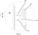
FIG. 3 is a side view of a partial structure of a terminal device in a first state disclosed in an embodiment of the present disclosure; -
FIG. 4 is a side view of a partial structure of a terminal device in a second state disclosed in an embodiment of the present disclosure; -
FIG. 5 is an exploded diagram of a partial structure of a terminal device according to an embodiment of the present disclosure; and -
FIG. 6 is an exploded diagram of a reflection part and a mounting base in a terminal device according to an embodiment of the present disclosure. - Dotted lines with arrows in
FIG. 3 andFIG. 4 indicate optical path directions. - Description of reference numerals:
100-Display assembly, 110-Light transmitting hole, 120-Display screen, 130-Transparent cover, 200-Optical component, 300-Secondary display assembly, 400-Reflection part, 410-Second sleeve, 500-Mounting base, 510-Base body, 511-Mounting surface, 512-Mounting part, 513-Protrusion part, 520-First sleeve, 600-Rotation shaft. - To make the objects, technical solutions, and advantages of the present disclosure clearer, the following clearly and completely describes the technical solutions of the present disclosure with reference to specific embodiments of the present disclosure and corresponding accompanying drawings. Apparently, the described embodiments are only some rather than all embodiments of the present disclosure. Based on the embodiments of the present disclosure, all other embodiments obtained by a person of ordinary skill in the art without creative efforts fall within the protection scope of the present disclosure.
- The technical solutions disclosed in the embodiments of the present disclosure are described in detail below with reference to the accompanying drawings.
- As shown in
FIG. 1 to FIG. 6 , an embodiment of the present disclosure discloses a terminal device, and the terminal device includes a housing, adisplay assembly 100, anoptical component 200, asecondary display assembly 300, areflection part 400, and a drive component. - The housing is a basis on which other components of the terminal device are mounted, and the housing may specifically include a middle frame. The
display assembly 100 is disposed on the housing, and may be specifically disposed on the middle frame. Alight transmitting hole 110 is disposed on thedisplay assembly 100, thedisplay assembly 100 may include adisplay screen 120 and atransparent cover 130, and thetransparent cover 130 may cover thedisplay screen 120. Specifically, thelight transmitting hole 110 may be a round hole, and may also be a hole in another shape. This is not limited in the present disclosure. - The
optical component 200 is disposed in the housing, and theoptical component 200 may emit light, or may receive light. Specifically, in this embodiment of this application, theoptical component 200 may include at least one of a camera, a sensor, and a supplement lamp. Certainly, theoptical component 200 may also include another component that can emit light or can receive light. In this embodiment of the present disclosure, theoptical component 200 is opposite to thelight transmitting hole 110. Therefore, light in an external environment can pass through thelight transmitting hole 110 and enter theoptical component 200, or light emitted by theoptical component 200 can be emitted through thelight transmitting hole 110. A position of thelight transmitting hole 110 on thedisplay assembly 100 may be selected based on a specific form of theoptical component 200. For example, thelight transmitting hole 110 may be located on the top of thedisplay assembly 100, and may be specifically located at the top left corner, the top right corner, or the middle part of thedisplay assembly 100. - The
secondary display assembly 300 is disposed in the housing, thesecondary display assembly 300 has a display function. Thereflection part 400 is movably disposed in the housing, thereflection part 400 can reflect information displayed by thesecondary display assembly 300 to thelight transmitting hole 110, and a user can observe, from an appearance surface of the terminal device, the information displayed by thesecondary display assembly 300. Optionally, thereflection part 400 may be a plane mirror, or another structure with a light reflection capability. It should be noted that, during mounting of thesecondary display assembly 300 and thereflection part 400, structural parameters such as mounting positions and mounting angles of thesecondary display assembly 300 and thereflection part 400 may be adjusted, so that thesecondary display assembly 300 and thereflection part 400 do not interfere with theoptical component 200, to further ensure that both theoptical component 200 and thesecondary display assembly 300 can independently work normally. - The drive component is disposed in the housing, and the drive component is connected to the
reflection part 400, and can drive the reflection part to move between a first state and a second state. Optionally, the drive component may be a drive motor, a magnetic drive component, or another structure that can drive thereflection part 400 to move. In the first state, theoptical component 200 works, and thesecondary display assembly 300 does not work. In this case, an optical channel is formed between thelight transmitting hole 110 on thedisplay assembly 100 and theoptical component 200, and thereflection part 400 is located outside the optical channel, so that the light in the external environment may pass through thelight transmitting hole 110 and enter theoptical component 200, or the light emitted by theoptical component 200 can be emitted through thelight transmitting hole 110. In the second state, theoptical component 200 does not work, and thesecondary display assembly 300 works. In this case, thereflection part 400 is located between thelight transmitting hole 110 and theoptical component 200, and reflects, to thelight transmitting hole 110, the light emitted by thesecondary display assembly 300, so that the user can observe the information displayed by thesecondary display assembly 300. In this second state, the information displayed by thesecondary display assembly 300 and the information displayed by thedisplay component 100 may be concatenated to form a complete picture, and there is no boundary in a picture observed by the user. Certainly, thesecondary display assembly 300 can also display information independently, and does not cooperate with thedisplay component 100. - It can be learned from the foregoing content that the
optical component 200 and thesecondary display assembly 300 may work independently. When theoptical component 200 does not work, the light emitted by thesecondary display assembly 300 may be reflected to thelight transmitting hole 110 by thereflection part 400, so that information may be displayed on thelight transmitting hole 110, thereby increasing utilization of a display area of thedisplay assembly 100, to increase a screen-to-body ratio of the terminal device. In addition, in this solution, a hole for theoptical component 200 to enter or exit the housing does not need to be disposed on the housing, so that integrity of the housing is not damaged, appearance quality of the terminal device is improved, and waterproof and dust-proof performance of the terminal device is better. - In addition, in this embodiment of the present disclosure, the
reflection part 400 is movably disposed in the housing, a position of thereflection part 400 can be adjusted, so that thesecondary display assembly 300 and theoptical component 200 independently work normally. Therefore, positions at which thesecondary display assembly 300 and thereflection part 400 can be set more flexibly, and the information displayed by thesecondary display assembly 300 can be more accurately output to thelight transmitting hole 110. - To reduce, as much as possible, space occupied by the
secondary display assembly 300, in this embodiment of the present disclosure, thesecondary display assembly 300 is parallel to an axis direction of thelight transmitting hole 110. In other words, a plane in which thesecondary display assembly 300 is located is parallel to the axis direction of thelight transmitting hole 110, so that thesecondary display assembly 300 can fully use space in a thickness direction of the terminal device. Further, to enable the information displayed by thesecondary display assembly 300 to be more accurately output to thelight transmitting hole 110, in the second state, an included angle between thereflection part 400 and thesecondary display assembly 300 is 45°. In this case, the light emitted by thesecondary display assembly 300 may be output in a direction parallel to an axis of thelight transmitting hole 110. - In a specific embodiment, the
reflection part 400 is disposed in at least the following two manners: In the first manner, thereflection part 400 is movably disposed in the housing; and in the second manner, thereflection part 400 is rotatably disposed in the housing. Relatively, in the first setting manner, moving space of thereflection part 400 is relatively large, and therefore, large space in the housing is occupied, which is not conducive to arrangement of other components in the housing; and in the second setting manner, moving space of thereflection part 400 is reduced, and therefore, it is more conducive to structural layout of the terminal device. Therefore, in some optional embodiments, thereflection part 400 in the present disclosure is rotatably disposed in the housing, in other words, thereflection part 400 is hinged to the housing, and the drive part drives thereflection part 400 to rotate relative to the housing. - When the
reflection part 400 rotates relative to the housing, in the second state, thereflection part 400 may accurately reflect the information displayed by thesecondary display assembly 300 to thelight transmitting hole 110. A position of thereflection part 400 in the first state is relatively flexible, provided that light propagation between thelight transmitting hole 110 and theoptical component 200 is not blocked. Considering that space in the housing is very valuable, thereflection part 400 may be as close to an optical channel between thelight transmitting hole 110 and theoptical component 200 as possible. In the first state, thereflection part 400 is parallel to the axis direction of thelight transmitting hole 110. In this case, thereflection part 400 may exactly avoid the optical channel, and does not need to be too far away from the optical channel, so that a rotation amplitude of thereflection part 400 is smaller, and space required for rotation of thereflection part 400 is further reduced, thereby facilitating arrangement of the components in the housing. - In an optional embodiment, the housing of the terminal device may further include a mounting
base 500. The mountingbase 500 may be mounted on a middle frame, and thereflection part 400 is hinged to the mountingbase 500, to be rotatably disposed in the housing. The mountingbase 500 has a mountingsurface 511, and thesecondary display assembly 300 is disposed on the mountingsurface 511. The mountingsurface 511 herein may be disposed as a plane. When thesecondary display assembly 300 is disposed along the axis direction of thelight transmitting hole 110, the mountingsurface 511 is parallel to the axis direction of thelight transmitting hole 110. The mountingbase 500 implements mounting of thesecondary display assembly 300 and thereflection part 400 in the housing at the same time, so that relative position accuracy between thesecondary display assembly 300 and thereflection part 400 can be better ensured, and output accuracy of the information displayed on thesecondary display assembly 300 is further improved. - There are many options for a hinge structure between the
reflection part 400 and the mountingbase 500. For example, thereflection part 400 may be connected by using a flexible connector, and the flexible connector may be deformed, so that thereflection part 400 may rotate relative to the mountingbase 500. However, in this manner, position accuracy of thereflection part 400 relative to the mountingbase 500 is relatively low, so that relative position accuracy of thereflection part 400 relative to thesecondary display assembly 300 cannot be reliably ensured. In view of this, as shown inFIG. 6 , in this embodiment of the present disclosure, the mountingbase 500 may include abase body 510 and afirst sleeve 520 disposed on thebase body 510. Thebase body 510 is provided with the foregoing mountingsurface 511, thereflection part 400 is provided with asecond sleeve 410, and thereflection part 400 and the mountingbase 500 are hinged by arotation shaft 600 that penetrates thefirst sleeve 520 and thesecond sleeve 410. A contact area between therotation shaft 600 and both thefirst sleeve 520 and thesecond sleeve 410 is relatively large. Therefore, when thereflection part 400 rotates relative to the mountingbase 500, position accuracy between thereflection part 400 and the mountingbase 500 is more easily ensured. - Only one
first sleeve 520 and only onesecond sleeve 410 may be disposed. However, to improve stability in a rotation process of thereflection part 400 and position precision of thereflection part 400 relative to the mountingbase 500, at least one of thefirst sleeve 520 and thesecond sleeve 410 may be disposed in a plural form, and thefirst sleeve 520 and thesecond sleeve 410 may be alternately arranged. - Further, to help limit the rotation amplitude of the
reflection part 400, one of thefirst sleeve 520 and thesecond sleeve 410 is disposed with a stopping convex part, and the other is disposed with a stopping groove, where the stopping convex part extends into the stopping groove, and both thefirst sleeve 520 and thesecond sleeve 410 cooperate with an upper limit in a relative rotation direction of thefirst sleeve 520 and thesecond sleeve 410. When thefirst sleeve 520 rotates relative to thesecond sleeve 410, the stopping convex part slides in the stopping groove, and when the stopping convex part slides to a sidewall of the stopping groove, the sidewall prevents the stopping convex part from continuing to slide, so that thefirst sleeve 520 and thesecond sleeve 410 cannot continue to rotate relative to each other, to achieve the foregoing purpose. It should be noted that both rotation amplitudes of thereflection part 400 in two opposite directions may be limited by the stopping convex part and the stopping groove herein. Specifically, when the stopping convex part cooperates with an upper limit in one of sidewalls of the stopping groove, a rotation amplitude of thereflection part 400 in one direction may be limited. When the stopping convex part cooperates with an upper limit in another sidewall of the stopping groove, a rotation amplitude of thereflection part 400 in another direction may be limited. - When the terminal device works, the
reflection part 400 moves frequently. If thesecondary display assembly 300 is relatively close to thereflection part 400, once a moving range of thereflection part 400 exceeds a preset range, thereflection part 400 easily collides with thesecondary display assembly 300, and consequently, thesecondary display assembly 300 is damaged. To prevent this case, the foregoingbase body 510 may include a mountingpart 512 and a protrusion part 513, where the protrusion part 513 is connected to the mountingpart 512, the protrusion part 513 protrudes from the mountingpart 512, the mountingsurface 511 is located on the mountingpart 512, and thefirst sleeve 520 is disposed on the protrusion part 513. After such setting, a distance between thereflection part 400 and thesecondary display assembly 300 increases. Even if the moving range of thereflection part 400 is abnormal, thesecondary display assembly 300 does not easily collide with thereflection part 400, and therefore, a working life of thesecondary display assembly 300 is prolonged. In addition, thesecondary display assembly 300 may be located between thedisplay component 100 and the protrusion part 513, so that the protrusion part 513 may separate thesecondary display assembly 300 from another component, to prevent light emitted or reflected by another component from affecting normal display of thesecondary display assembly 300, thereby improving a display effect of thesecondary display assembly 300. - In this embodiment of the disclosure, the housing usually has a frame, the frame includes a top part, and the
reflection part 400 and thesecondary display assembly 300 may be arranged in a direction perpendicular to the top part (that is, a Y direction inFIG. 3 ), to facilitate structural design of the terminal device. Specifically, thereflection part 400 may be closer to the top part of the frame than thesecondary display assembly 300, or thesecondary display assembly 300 may be closer to the top part of the frame than thereflection part 400. In view of a fact that there are a relatively large number of components that need to be arranged at the top part, space is smaller, and interference is easily caused between components, in some optional embodiments, thereflection part 400 is closer to the top part of the frame than thesecondary display assembly 300, in other words, thereflection part 400 is located between the top part of the frame and thesecondary display assembly 300. - The terminal device disclosed in the embodiments of the present disclosure may be a smartphone, a tablet computer, an e-book reader, or a wearable device. Certainly, the terminal device may also be another device, which is not limited in this embodiment of the present disclosure.
- The foregoing embodiments of the present disclosure focus on describing differences between the embodiments, and different optimization features of the embodiments may be combined to form better embodiments provided that they are not contradictory. Considering brevity, details are not described herein again.
- The foregoing descriptions are merely embodiments of the present disclosure, and are not intended to limit the present disclosure. For a person skilled in the art, various changes and variations may be made in the present disclosure. Any modification, equivalent replacement, and improvement made in the principles of the present disclosure shall be included in the scope of the claims of the present disclosure.
Claims (10)
- A terminal device, comprising:a housing;a display assembly, wherein the display assembly is disposed on the housing, and a light transmitting hole is disposed on the display assembly;an optical component, wherein the optical component is disposed in the housing, and the optical component is opposite to the light transmitting hole;a secondary display assembly, wherein the secondary display assembly is disposed in the housing;a reflection part, wherein the reflection part is movably disposed in the housing; anda drive component, wherein the drive component is disposed in the housing, and the drive component is connected to the reflection part, and drives the reflection part to move between a first state and a second state; in the first state, the reflection part is located outside an optical channel between the optical component and the light transmitting hole; and in the second state, the reflection part is located between the light transmitting hole and the optical component, and reflect, to the light transmitting hole, light emitted by the secondary display assembly.
- The terminal device according to claim 1, wherein the secondary display assembly is parallel to an axis direction of the light transmitting hole.
- The terminal device according to claim 2, wherein in the second state, an included angle between the reflection part and the secondary display assembly is 45°.
- The terminal device according to claim 1, wherein the reflection part is hinged to the housing, and the drive component drives the reflection part to rotate relative to the housing.
- The terminal device according to claim 4, wherein in the first state, the reflection part is parallel to an axis direction of the light transmitting hole.
- The terminal device according to claim 4, wherein the housing comprises a mounting base, the reflection part is hinged to the mounting base, the mounting base has a mounting surface, and the secondary display assembly is disposed on the mounting surface.
- The terminal device according to claim 6, wherein the mounting base comprises a base body and a first sleeve disposed on the base body, the base body is provided with the mounting surface, the reflection part is provided with a second sleeve, and the reflection part and the mounting base are hinged by using a rotation shaft that penetrates the first sleeve and the second sleeve.
- The terminal device according to claim 7, wherein one of the first sleeve and the second sleeve is disposed with a stopping convex part, and the other is disposed with a stopping groove, wherein the stopping convex part extends into the stopping groove, and in a relative rotation direction of the first sleeve and the second sleeve, the stopping convex part is fitted with the stopping groove cooperate for position limitation.
- The terminal device according to claim 7, wherein the base body comprises a mounting part and a protrusion part, the protrusion part is connected to the mounting part, the protrusion part protrudes from the mounting part, the mounting surface is located on the mounting part, and the first sleeve is disposed on the protrusion part.
- The terminal device according to any one of claims 1 to 9, wherein the optical component comprises at least one of a camera, a sensor, and a supplement lamp.
Applications Claiming Priority (2)
| Application Number | Priority Date | Filing Date | Title |
|---|---|---|---|
| CN201910403615.1A CN110035158B (en) | 2019-05-15 | 2019-05-15 | Terminal Equipment |
| PCT/CN2020/086415 WO2020228506A1 (en) | 2019-05-15 | 2020-04-23 | Terminal device |
Publications (3)
| Publication Number | Publication Date |
|---|---|
| EP3972228A1 true EP3972228A1 (en) | 2022-03-23 |
| EP3972228A4 EP3972228A4 (en) | 2022-06-29 |
| EP3972228B1 EP3972228B1 (en) | 2025-11-12 |
Family
ID=67242232
Family Applications (1)
| Application Number | Title | Priority Date | Filing Date |
|---|---|---|---|
| EP20806638.1A Active EP3972228B1 (en) | 2019-05-15 | 2020-04-23 | Terminal device |
Country Status (5)
| Country | Link |
|---|---|
| US (1) | US11876919B2 (en) |
| EP (1) | EP3972228B1 (en) |
| CN (1) | CN110035158B (en) |
| ES (1) | ES3054409T3 (en) |
| WO (1) | WO2020228506A1 (en) |
Families Citing this family (3)
| Publication number | Priority date | Publication date | Assignee | Title |
|---|---|---|---|---|
| CN110113458A (en) * | 2019-05-15 | 2019-08-09 | 维沃移动通信有限公司 | Terminal device |
| CN110035158B (en) * | 2019-05-15 | 2021-01-08 | 维沃移动通信有限公司 | Terminal Equipment |
| CN115174796B (en) * | 2022-08-30 | 2023-01-31 | 荣耀终端有限公司 | Assembly method, assembly structure and electronic equipment of front camera |
Family Cites Families (20)
| Publication number | Priority date | Publication date | Assignee | Title |
|---|---|---|---|---|
| JP2004080147A (en) * | 2002-08-12 | 2004-03-11 | Denso Wave Inc | Portable terminal apparatus with camera |
| KR20130104764A (en) * | 2012-03-15 | 2013-09-25 | 엘지전자 주식회사 | Mobile terminal |
| CN105049687B (en) * | 2015-06-30 | 2018-12-11 | 广东欧珀移动通信有限公司 | Double-camera mobile terminal |
| KR102373308B1 (en) * | 2017-04-06 | 2022-03-11 | 삼성전자주식회사 | Electronic device including a housing having at least one through hole |
| CN107241467B (en) * | 2017-05-11 | 2020-08-07 | Oppo广东移动通信有限公司 | Electronic device |
| CN109597267B (en) * | 2017-09-30 | 2020-06-23 | 昆山国显光电有限公司 | Display device and display screen module |
| CN109597268B (en) * | 2017-09-30 | 2020-09-22 | 昆山国显光电有限公司 | display device |
| CN109599029B (en) * | 2017-09-30 | 2020-06-23 | 昆山国显光电有限公司 | Display screen, display screen module and display device |
| CN107635038B (en) | 2017-10-31 | 2025-02-18 | 北京小米移动软件有限公司 | Electronic devices |
| KR102418612B1 (en) * | 2018-01-03 | 2022-07-08 | 엘지전자 주식회사 | Mobile terminal |
| CN108254963A (en) | 2018-03-20 | 2018-07-06 | 京东方科技集团股份有限公司 | A kind of display panel, display module, display device and its driving method |
| CN108376019A (en) * | 2018-05-28 | 2018-08-07 | Oppo广东移动通信有限公司 | Electronic device |
| CN108965519B (en) | 2018-07-04 | 2021-04-06 | 孟楚雁 | Terminal equipment |
| CN109348097A (en) | 2018-09-29 | 2019-02-15 | 上海与德科技有限公司 | Periscopic photographic device and terminal device |
| CN109451106B (en) | 2018-11-16 | 2020-06-12 | Oppo广东移动通信有限公司 | Electronic device |
| CN109584741A (en) * | 2018-12-04 | 2019-04-05 | 深圳绿米联创科技有限公司 | Optics module and electronic equipment under a kind of concealed screen |
| CN110088820B (en) * | 2019-03-11 | 2021-12-03 | 京东方科技集团股份有限公司 | Display device and operation method thereof |
| CN110035158B (en) * | 2019-05-15 | 2021-01-08 | 维沃移动通信有限公司 | Terminal Equipment |
| CN110211500A (en) * | 2019-06-27 | 2019-09-06 | Oppo广东移动通信有限公司 | Image display module, method, terminal device and storage medium |
| CN209930366U (en) * | 2019-07-03 | 2020-01-10 | 北京小米移动软件有限公司 | Camera mounting structure and terminal equipment |
-
2019
- 2019-05-15 CN CN201910403615.1A patent/CN110035158B/en active Active
-
2020
- 2020-04-23 WO PCT/CN2020/086415 patent/WO2020228506A1/en not_active Ceased
- 2020-04-23 ES ES20806638T patent/ES3054409T3/en active Active
- 2020-04-23 EP EP20806638.1A patent/EP3972228B1/en active Active
-
2021
- 2021-11-12 US US17/525,642 patent/US11876919B2/en active Active
Also Published As
| Publication number | Publication date |
|---|---|
| US20220078269A1 (en) | 2022-03-10 |
| EP3972228B1 (en) | 2025-11-12 |
| CN110035158A (en) | 2019-07-19 |
| EP3972228A4 (en) | 2022-06-29 |
| ES3054409T3 (en) | 2026-02-03 |
| US11876919B2 (en) | 2024-01-16 |
| WO2020228506A1 (en) | 2020-11-19 |
| CN110035158B (en) | 2021-01-08 |
Similar Documents
| Publication | Publication Date | Title |
|---|---|---|
| US11463565B2 (en) | Image capturing device and mobile electronic device | |
| US11876919B2 (en) | Terminal device | |
| US12332546B2 (en) | Optical element driving mechanism | |
| US20250355323A1 (en) | Variable aperture, camera module, and electronic device | |
| JP6999687B2 (en) | Virtual reality head mount device | |
| CN109302555B (en) | Camera assembly and terminal equipment | |
| US11743368B2 (en) | Screen component, mobile phone and mobile device | |
| US20210141583A1 (en) | Display device and operation method thereof | |
| US12578544B2 (en) | Optical element driving mechanism | |
| US11867925B2 (en) | Driving mechanism for optical element | |
| WO2020042883A1 (en) | Mobile terminal | |
| US20240369910A1 (en) | Camera device with image compensation and autofocus function | |
| CN110519494B (en) | Optical module and electronic equipment | |
| US12342063B2 (en) | Camera module and electronic device including a protection structural member, a gimbal camera and a support seat | |
| US9154680B2 (en) | Camera module for an optical touch screen | |
| KR102493390B1 (en) | A camera module and optical instrument including the same | |
| EP3761626B1 (en) | Concealable camera and electronic device having a concealable camera | |
| US20240019775A1 (en) | Camera module and electronic device | |
| KR20240143200A (en) | Camera module | |
| WO2019228050A1 (en) | Imaging component, electronic component, electronic apparatus, and control method for electronic apparatus | |
| WO2020228740A1 (en) | Terminal device | |
| US10616437B2 (en) | Optical device having housing rotatable relative to fixing member detachably affixed to scanner | |
| KR102842339B1 (en) | Camera module | |
| WO2026016975A1 (en) | Anti-shake motor and related product thereof | |
| TW202221451A (en) | Electronic device |
Legal Events
| Date | Code | Title | Description |
|---|---|---|---|
| STAA | Information on the status of an ep patent application or granted ep patent |
Free format text: STATUS: THE INTERNATIONAL PUBLICATION HAS BEEN MADE |
|
| PUAI | Public reference made under article 153(3) epc to a published international application that has entered the european phase |
Free format text: ORIGINAL CODE: 0009012 |
|
| STAA | Information on the status of an ep patent application or granted ep patent |
Free format text: STATUS: REQUEST FOR EXAMINATION WAS MADE |
|
| 17P | Request for examination filed |
Effective date: 20211203 |
|
| AK | Designated contracting states |
Kind code of ref document: A1 Designated state(s): AL AT BE BG CH CY CZ DE DK EE ES FI FR GB GR HR HU IE IS IT LI LT LU LV MC MK MT NL NO PL PT RO RS SE SI SK SM TR |
|
| A4 | Supplementary search report drawn up and despatched |
Effective date: 20220530 |
|
| RIC1 | Information provided on ipc code assigned before grant |
Ipc: G06F 1/16 20060101ALI20220523BHEP Ipc: H04M 1/22 20060101ALI20220523BHEP Ipc: H04M 1/02 20060101AFI20220523BHEP |
|
| DAV | Request for validation of the european patent (deleted) | ||
| DAX | Request for extension of the european patent (deleted) | ||
| STAA | Information on the status of an ep patent application or granted ep patent |
Free format text: STATUS: EXAMINATION IS IN PROGRESS |
|
| 17Q | First examination report despatched |
Effective date: 20241017 |
|
| GRAP | Despatch of communication of intention to grant a patent |
Free format text: ORIGINAL CODE: EPIDOSNIGR1 |
|
| STAA | Information on the status of an ep patent application or granted ep patent |
Free format text: STATUS: GRANT OF PATENT IS INTENDED |
|
| INTG | Intention to grant announced |
Effective date: 20250709 |
|
| GRAS | Grant fee paid |
Free format text: ORIGINAL CODE: EPIDOSNIGR3 |
|
| GRAA | (expected) grant |
Free format text: ORIGINAL CODE: 0009210 |
|
| STAA | Information on the status of an ep patent application or granted ep patent |
Free format text: STATUS: THE PATENT HAS BEEN GRANTED |
|
| AK | Designated contracting states |
Kind code of ref document: B1 Designated state(s): AL AT BE BG CH CY CZ DE DK EE ES FI FR GB GR HR HU IE IS IT LI LT LU LV MC MK MT NL NO PL PT RO RS SE SI SK SM TR |
|
| REG | Reference to a national code |
Ref country code: CH Ref legal event code: F10 Free format text: ST27 STATUS EVENT CODE: U-0-0-F10-F00 (AS PROVIDED BY THE NATIONAL OFFICE) Effective date: 20251112 Ref country code: GB Ref legal event code: FG4D |
|
| REG | Reference to a national code |
Ref country code: IE Ref legal event code: FG4D |
|
| REG | Reference to a national code |
Ref country code: DE Ref legal event code: R096 Ref document number: 602020062164 Country of ref document: DE |
|
| REG | Reference to a national code |
Ref country code: NL Ref legal event code: FP |
|
| REG | Reference to a national code |
Ref country code: ES Ref legal event code: FG2A Ref document number: 3054409 Country of ref document: ES Kind code of ref document: T3 Effective date: 20260203 |
|
| PGFP | Annual fee paid to national office [announced via postgrant information from national office to epo] |
Ref country code: GB Payment date: 20260312 Year of fee payment: 7 |
|
| REG | Reference to a national code |
Ref country code: LT Ref legal event code: MG9D |
|
| PG25 | Lapsed in a contracting state [announced via postgrant information from national office to epo] |
Ref country code: NO Free format text: LAPSE BECAUSE OF FAILURE TO SUBMIT A TRANSLATION OF THE DESCRIPTION OR TO PAY THE FEE WITHIN THE PRESCRIBED TIME-LIMIT Effective date: 20260212 |
|
| PG25 | Lapsed in a contracting state [announced via postgrant information from national office to epo] |
Ref country code: AT Free format text: LAPSE BECAUSE OF FAILURE TO SUBMIT A TRANSLATION OF THE DESCRIPTION OR TO PAY THE FEE WITHIN THE PRESCRIBED TIME-LIMIT Effective date: 20251112 Ref country code: FI Free format text: LAPSE BECAUSE OF FAILURE TO SUBMIT A TRANSLATION OF THE DESCRIPTION OR TO PAY THE FEE WITHIN THE PRESCRIBED TIME-LIMIT Effective date: 20251112 Ref country code: HR Free format text: LAPSE BECAUSE OF FAILURE TO SUBMIT A TRANSLATION OF THE DESCRIPTION OR TO PAY THE FEE WITHIN THE PRESCRIBED TIME-LIMIT Effective date: 20251112 |
|
| PGFP | Annual fee paid to national office [announced via postgrant information from national office to epo] |
Ref country code: IT Payment date: 20260320 Year of fee payment: 7 |
|
| REG | Reference to a national code |
Ref country code: AT Ref legal event code: MK05 Ref document number: 1857798 Country of ref document: AT Kind code of ref document: T Effective date: 20251112 |
|
| PGFP | Annual fee paid to national office [announced via postgrant information from national office to epo] |
Ref country code: NL Payment date: 20260317 Year of fee payment: 7 |
|
| PG25 | Lapsed in a contracting state [announced via postgrant information from national office to epo] |
Ref country code: RS Free format text: LAPSE BECAUSE OF FAILURE TO SUBMIT A TRANSLATION OF THE DESCRIPTION OR TO PAY THE FEE WITHIN THE PRESCRIBED TIME-LIMIT Effective date: 20260212 |
|
| PG25 | Lapsed in a contracting state [announced via postgrant information from national office to epo] |
Ref country code: IS Free format text: LAPSE BECAUSE OF FAILURE TO SUBMIT A TRANSLATION OF THE DESCRIPTION OR TO PAY THE FEE WITHIN THE PRESCRIBED TIME-LIMIT Effective date: 20260312 |
|
| PGFP | Annual fee paid to national office [announced via postgrant information from national office to epo] |
Ref country code: FR Payment date: 20260309 Year of fee payment: 7 |
|
| PG25 | Lapsed in a contracting state [announced via postgrant information from national office to epo] |
Ref country code: PT Free format text: LAPSE BECAUSE OF FAILURE TO SUBMIT A TRANSLATION OF THE DESCRIPTION OR TO PAY THE FEE WITHIN THE PRESCRIBED TIME-LIMIT Effective date: 20260312 |
|
| PG25 | Lapsed in a contracting state [announced via postgrant information from national office to epo] |
Ref country code: PL Free format text: LAPSE BECAUSE OF FAILURE TO SUBMIT A TRANSLATION OF THE DESCRIPTION OR TO PAY THE FEE WITHIN THE PRESCRIBED TIME-LIMIT Effective date: 20251112 |
|
| PG25 | Lapsed in a contracting state [announced via postgrant information from national office to epo] |
Ref country code: LV Free format text: LAPSE BECAUSE OF FAILURE TO SUBMIT A TRANSLATION OF THE DESCRIPTION OR TO PAY THE FEE WITHIN THE PRESCRIBED TIME-LIMIT Effective date: 20251112 |
|
| PG25 | Lapsed in a contracting state [announced via postgrant information from national office to epo] |
Ref country code: BG Free format text: LAPSE BECAUSE OF FAILURE TO SUBMIT A TRANSLATION OF THE DESCRIPTION OR TO PAY THE FEE WITHIN THE PRESCRIBED TIME-LIMIT Effective date: 20251112 |