EP3972117A1 - High frequency injection transition disturbance elimination for a salient pole electric machine - Google Patents
High frequency injection transition disturbance elimination for a salient pole electric machine Download PDFInfo
- Publication number
- EP3972117A1 EP3972117A1 EP21194800.5A EP21194800A EP3972117A1 EP 3972117 A1 EP3972117 A1 EP 3972117A1 EP 21194800 A EP21194800 A EP 21194800A EP 3972117 A1 EP3972117 A1 EP 3972117A1
- Authority
- EP
- European Patent Office
- Prior art keywords
- hfi
- voltage
- compensation
- compensation pulse
- transition
- Prior art date
- Legal status (The legal status is an assumption and is not a legal conclusion. Google has not performed a legal analysis and makes no representation as to the accuracy of the status listed.)
- Granted
Links
- 230000007704 transition Effects 0.000 title claims abstract description 89
- 238000002347 injection Methods 0.000 title claims abstract description 54
- 239000007924 injection Substances 0.000 title claims abstract description 54
- 230000008030 elimination Effects 0.000 title abstract description 8
- 238000003379 elimination reaction Methods 0.000 title abstract description 8
- 238000000034 method Methods 0.000 claims description 35
- 238000004590 computer program Methods 0.000 claims description 23
- 238000010586 diagram Methods 0.000 description 28
- 230000006870 function Effects 0.000 description 25
- 230000004907 flux Effects 0.000 description 6
- 230000000644 propagated effect Effects 0.000 description 4
- 238000000926 separation method Methods 0.000 description 4
- 230000001360 synchronised effect Effects 0.000 description 4
- 230000003287 optical effect Effects 0.000 description 3
- 230000008569 process Effects 0.000 description 3
- 230000004044 response Effects 0.000 description 3
- 238000003491 array Methods 0.000 description 2
- 230000001934 delay Effects 0.000 description 2
- 238000000605 extraction Methods 0.000 description 2
- 239000000463 material Substances 0.000 description 2
- 230000000630 rising effect Effects 0.000 description 2
- 239000004065 semiconductor Substances 0.000 description 2
- 230000009466 transformation Effects 0.000 description 2
- 239000003990 capacitor Substances 0.000 description 1
- 230000000694 effects Effects 0.000 description 1
- 239000000835 fiber Substances 0.000 description 1
- 238000004519 manufacturing process Methods 0.000 description 1
- 238000012544 monitoring process Methods 0.000 description 1
- 230000006855 networking Effects 0.000 description 1
- 239000013307 optical fiber Substances 0.000 description 1
- 239000000243 solution Substances 0.000 description 1
- 230000003313 weakening effect Effects 0.000 description 1
- 238000004804 winding Methods 0.000 description 1
Images


Classifications
-
- H—ELECTRICITY
- H02—GENERATION; CONVERSION OR DISTRIBUTION OF ELECTRIC POWER
- H02P—CONTROL OR REGULATION OF ELECTRIC MOTORS, ELECTRIC GENERATORS OR DYNAMO-ELECTRIC CONVERTERS; CONTROLLING TRANSFORMERS, REACTORS OR CHOKE COILS
- H02P21/00—Arrangements or methods for the control of electric machines by vector control, e.g. by control of field orientation
- H02P21/05—Arrangements or methods for the control of electric machines by vector control, e.g. by control of field orientation specially adapted for damping motor oscillations, e.g. for reducing hunting
-
- H—ELECTRICITY
- H02—GENERATION; CONVERSION OR DISTRIBUTION OF ELECTRIC POWER
- H02P—CONTROL OR REGULATION OF ELECTRIC MOTORS, ELECTRIC GENERATORS OR DYNAMO-ELECTRIC CONVERTERS; CONTROLLING TRANSFORMERS, REACTORS OR CHOKE COILS
- H02P27/00—Arrangements or methods for the control of AC motors characterised by the kind of supply voltage
- H02P27/04—Arrangements or methods for the control of AC motors characterised by the kind of supply voltage using variable-frequency supply voltage, e.g. inverter or converter supply voltage
- H02P27/06—Arrangements or methods for the control of AC motors characterised by the kind of supply voltage using variable-frequency supply voltage, e.g. inverter or converter supply voltage using dc to ac converters or inverters
- H02P27/08—Arrangements or methods for the control of AC motors characterised by the kind of supply voltage using variable-frequency supply voltage, e.g. inverter or converter supply voltage using dc to ac converters or inverters with pulse width modulation
- H02P27/085—Arrangements or methods for the control of AC motors characterised by the kind of supply voltage using variable-frequency supply voltage, e.g. inverter or converter supply voltage using dc to ac converters or inverters with pulse width modulation wherein the PWM mode is adapted on the running conditions of the motor, e.g. the switching frequency
-
- H—ELECTRICITY
- H02—GENERATION; CONVERSION OR DISTRIBUTION OF ELECTRIC POWER
- H02P—CONTROL OR REGULATION OF ELECTRIC MOTORS, ELECTRIC GENERATORS OR DYNAMO-ELECTRIC CONVERTERS; CONTROLLING TRANSFORMERS, REACTORS OR CHOKE COILS
- H02P23/00—Arrangements or methods for the control of AC motors characterised by a control method other than vector control
- H02P23/14—Estimation or adaptation of motor parameters, e.g. rotor time constant, flux, speed, current or voltage
-
- H—ELECTRICITY
- H02—GENERATION; CONVERSION OR DISTRIBUTION OF ELECTRIC POWER
- H02P—CONTROL OR REGULATION OF ELECTRIC MOTORS, ELECTRIC GENERATORS OR DYNAMO-ELECTRIC CONVERTERS; CONTROLLING TRANSFORMERS, REACTORS OR CHOKE COILS
- H02P21/00—Arrangements or methods for the control of electric machines by vector control, e.g. by control of field orientation
- H02P21/22—Current control, e.g. using a current control loop
-
- H—ELECTRICITY
- H02—GENERATION; CONVERSION OR DISTRIBUTION OF ELECTRIC POWER
- H02P—CONTROL OR REGULATION OF ELECTRIC MOTORS, ELECTRIC GENERATORS OR DYNAMO-ELECTRIC CONVERTERS; CONTROLLING TRANSFORMERS, REACTORS OR CHOKE COILS
- H02P21/00—Arrangements or methods for the control of electric machines by vector control, e.g. by control of field orientation
- H02P21/24—Vector control not involving the use of rotor position or rotor speed sensors
-
- H—ELECTRICITY
- H02—GENERATION; CONVERSION OR DISTRIBUTION OF ELECTRIC POWER
- H02P—CONTROL OR REGULATION OF ELECTRIC MOTORS, ELECTRIC GENERATORS OR DYNAMO-ELECTRIC CONVERTERS; CONTROLLING TRANSFORMERS, REACTORS OR CHOKE COILS
- H02P27/00—Arrangements or methods for the control of AC motors characterised by the kind of supply voltage
- H02P27/04—Arrangements or methods for the control of AC motors characterised by the kind of supply voltage using variable-frequency supply voltage, e.g. inverter or converter supply voltage
- H02P27/06—Arrangements or methods for the control of AC motors characterised by the kind of supply voltage using variable-frequency supply voltage, e.g. inverter or converter supply voltage using dc to ac converters or inverters
- H02P27/08—Arrangements or methods for the control of AC motors characterised by the kind of supply voltage using variable-frequency supply voltage, e.g. inverter or converter supply voltage using dc to ac converters or inverters with pulse width modulation
-
- H—ELECTRICITY
- H02—GENERATION; CONVERSION OR DISTRIBUTION OF ELECTRIC POWER
- H02P—CONTROL OR REGULATION OF ELECTRIC MOTORS, ELECTRIC GENERATORS OR DYNAMO-ELECTRIC CONVERTERS; CONTROLLING TRANSFORMERS, REACTORS OR CHOKE COILS
- H02P29/00—Arrangements for regulating or controlling electric motors, appropriate for both AC and DC motors
- H02P29/50—Reduction of harmonics
-
- H—ELECTRICITY
- H02—GENERATION; CONVERSION OR DISTRIBUTION OF ELECTRIC POWER
- H02P—CONTROL OR REGULATION OF ELECTRIC MOTORS, ELECTRIC GENERATORS OR DYNAMO-ELECTRIC CONVERTERS; CONTROLLING TRANSFORMERS, REACTORS OR CHOKE COILS
- H02P6/00—Arrangements for controlling synchronous motors or other dynamo-electric motors using electronic commutation dependent on the rotor position; Electronic commutators therefor
- H02P6/14—Electronic commutators
- H02P6/16—Circuit arrangements for detecting position
- H02P6/18—Circuit arrangements for detecting position without separate position detecting elements
- H02P6/183—Circuit arrangements for detecting position without separate position detecting elements using an injected high frequency signal
-
- H—ELECTRICITY
- H02—GENERATION; CONVERSION OR DISTRIBUTION OF ELECTRIC POWER
- H02P—CONTROL OR REGULATION OF ELECTRIC MOTORS, ELECTRIC GENERATORS OR DYNAMO-ELECTRIC CONVERTERS; CONTROLLING TRANSFORMERS, REACTORS OR CHOKE COILS
- H02P2203/00—Indexing scheme relating to controlling arrangements characterised by the means for detecting the position of the rotor
- H02P2203/11—Determination or estimation of the rotor position or other motor parameters based on the analysis of high-frequency signals
-
- H—ELECTRICITY
- H02—GENERATION; CONVERSION OR DISTRIBUTION OF ELECTRIC POWER
- H02P—CONTROL OR REGULATION OF ELECTRIC MOTORS, ELECTRIC GENERATORS OR DYNAMO-ELECTRIC CONVERTERS; CONTROLLING TRANSFORMERS, REACTORS OR CHOKE COILS
- H02P2205/00—Indexing scheme relating to controlling arrangements characterised by the control loops
- H02P2205/05—Torque loop, i.e. comparison of the motor torque with a torque reference
-
- H—ELECTRICITY
- H02—GENERATION; CONVERSION OR DISTRIBUTION OF ELECTRIC POWER
- H02P—CONTROL OR REGULATION OF ELECTRIC MOTORS, ELECTRIC GENERATORS OR DYNAMO-ELECTRIC CONVERTERS; CONTROLLING TRANSFORMERS, REACTORS OR CHOKE COILS
- H02P2205/00—Indexing scheme relating to controlling arrangements characterised by the control loops
- H02P2205/07—Speed loop, i.e. comparison of the motor speed with a speed reference
Definitions
- the subject matter disclosed herein relates to high frequency injection transition disturbance elimination for salient pole electric machines.
- the apparatus includes a processor and a memory storing code executable by the processor.
- the processor directs an HFI transition for a motor.
- the processor determines compensation pulse voltages for an HFI compensation pulse.
- the processor further injects a sum of the HFI compensation pulse and an HFI voltage into a current regulator voltage output signal for a transition Pulse Width Modulation (PWM) cycle.
- PWM transition Pulse Width Modulation
- a method for HFI transition disturbance elimination is also disclosed.
- the method directs an HFI transition for a motor.
- the method determines compensation pulse voltages for an HFI compensation pulse.
- the method further injects a sum of the HFI compensation pulse and an HFI voltage into a current regulator voltage output signal for a compensation PWM cycle.
- the HFI compensation pulse settles an HFI current to a steady state.
- a computer program product for HFI transition disturbance elimination is also disclosed.
- a processor directs an HFI transition for a motor.
- the processor determines compensation pulse voltages for an HFI compensation pulse.
- the processor further injects a sum of the HFI compensation pulse and an HFI voltage into a current regulator voltage output signal for a compensation PWM cycle.
- the HFI compensation pulse settles an HFI current to a steady state.
- aspects of the present invention may be embodied as a system, method, and/or computer program product. Accordingly, aspects of the present invention may take the form of an entirely hardware embodiment, an entirely software embodiment (including firmware, resident software, micro-code, etc.) or an embodiment combining software and hardware aspects that may all generally be referred to herein as a "circuit,” "module,” or “system.” Furthermore, aspects of the present invention may take the form of a computer program product embodied in one or more computer readable medium(s) having program code embodied thereon.
- modules may be implemented as a hardware circuit comprising custom VLSI circuits or gate arrays, off-the-shelf semiconductors such as logic chips, transistors, or other discrete components.
- a module may also be implemented in programmable hardware devices such as field programmable gate arrays, programmable array logic, programmable logic devices or the like.
- Modules may also be implemented in software for execution by various types of processors.
- An identified module of program code may, for instance, comprise one or more physical or logical blocks of computer instructions which may, for instance, be organized as an object, procedure, or function. Nevertheless, the executables of an identified module need not be physically located together but may comprise disparate instructions stored in different locations which, when joined logically together, comprise the module and achieve the stated purpose for the module.
- a module of program code may be a single instruction, or many instructions, and may even be distributed over several different code segments, among different programs, and across several memory devices.
- operational data may be identified and illustrated herein within modules and may be embodied in any suitable form and organized within any suitable type of data structure. The operational data may be collected as a single data set or may be distributed over different locations including over different storage devices, and may exist, at least partially, merely as electronic signals on a system or network.
- the program code may be stored and/or propagated on in one or more computer readable medium(s).
- the computer readable medium may be a tangible computer readable storage medium storing the program code.
- the computer readable storage medium may be, for example, but not limited to, an electronic, magnetic, optical, electromagnetic, infrared, holographic, micromechanical, or semiconductor system, apparatus, or device, or any suitable combination of the foregoing.
- the computer readable storage medium may include but are not limited to a portable computer diskette, a hard disk, a random access memory (RAM), a read-only memory (ROM), an erasable programmable read-only memory (EPROM or Flash memory), a portable compact disc read-only memory (CD-ROM), a digital versatile disc (DVD), an optical storage device, a magnetic storage device, a holographic storage medium, a micromechanical storage device, or any suitable combination of the foregoing.
- a computer readable storage medium may be any tangible medium that can contain, and/or store program code for use by and/or in connection with an instruction execution system, apparatus, or device.
- the computer readable medium may also be a computer readable signal medium.
- a computer readable signal medium may include a propagated data signal with program code embodied therein, for example, in baseband or as part of a carrier wave. Such a propagated signal may take any of a variety of forms, including, but not limited to, electrical, electro-magnetic, magnetic, optical, or any suitable combination thereof
- a computer readable signal medium may be any computer readable medium that is not a computer readable storage medium and that can communicate, propagate, or transport program code for use by or in connection with an instruction execution system, apparatus, or device.
- Program code embodied on a computer readable signal medium may be transmitted using any appropriate medium, including but not limited to wireline, optical fiber, Radio Frequency (RF), or the like, or any suitable combination of the foregoing
- the computer readable medium may comprise a combination of one or more computer readable storage mediums and one or more computer readable signal mediums.
- program code may be both propagated as an electro-magnetic signal through a fiber optic cable for execution by a processor and stored on RAM storage device for execution by the processor.
- Program code for carrying out operations for aspects of the present invention may be written in any combination of one or more programming languages, including an object oriented programming language such as Python, Ruby, R, Java, Java Script, Smalltalk, C++, C sharp, Lisp, Clojure, PHP or the like and conventional procedural programming languages, such as the "C" programming language or similar programming languages.
- the program code may execute entirely on the user's computer, partly on the user's computer, as a stand-alone software package, partly on the user's computer and partly on a remote computer or entirely on the remote computer or server.
- the remote computer may be connected to the user's computer through any type of network, including a local area network (LAN) or a wide area network (WAN), or the connection may be made to an external computer (for example, through the Internet using an Internet Service Provider).
- LAN local area network
- WAN wide area network
- the computer program product may be shared, simultaneously serving multiple customers in a flexible, automated fashion.
- the computer program product may be integrated into a client, server and network environment by providing for the computer program product to coexist with applications, operating systems and network operating systems software and then installing the computer program product on the clients and servers in the environment where the computer program product will function.
- software is identified on the clients and servers including the network operating system where the computer program product will be deployed that are required by the computer program product or that work in conjunction with the computer program product. This includes the network operating system that is software that enhances a basic operating system by adding networking features.
- the embodiments may transmit data between electronic devices.
- the embodiments may further convert the data from a first format to a second format, including converting the data from a non-standard format to a standard format and/or converting the data from the standard format to a non-standard format.
- the embodiments may modify, update, and/or process the data.
- the embodiments may store the received, converted, modified, updated, and/or processed data.
- the embodiments may provide remote access to the data including the updated data.
- the embodiments may make the data and/or updated data available in real time.
- the embodiments may generate and transmit a message based on the data and/or updated data in real time.
- the program code may also be stored in a computer readable medium that can direct a computer, other programmable data processing apparatus, or other devices to function in a particular manner, such that the instructions stored in the computer readable medium produce an article of manufacture including instructions which implement the function/act specified in the schematic flowchart diagrams and/or schematic block diagrams block or blocks.
- the program code may also be loaded onto a computer, other programmable data processing apparatus, or other devices to cause a series of operational steps to be performed on the computer, other programmable apparatus or other devices to produce a computer implemented process such that the program code which executed on the computer or other programmable apparatus provide processes for implementing the functions/acts specified in the flowchart and/or block diagram block or blocks.
- each block in the schematic flowchart diagrams and/or schematic block diagrams may represent a module, segment, or portion of code, which comprises one or more executable instructions of the program code for implementing the specified logical function(s).
- Figure 1A is a schematic block diagram of an electric motor control system 100.
- the system 100 drives a motor 101 in response to a speed command 102.
- the motor 101 may be a salient motor 101.
- the electric motor control system 100 includes a plurality of function blocks that may be performed by hardware components, code executed by a processor, or combinations thereof.
- a converter 21 generates a drive current I a , I b , I c 143a-c that drives the motor 101 from a DC bus voltage V DC 167.
- the converter 21 may be a full bridge converter 21 comprising a capacitor 15 and a plurality of insulated gate bipolar transistors (IGBT) 11.
- the IGBT 11 may be driven by gate signals 17 generated by a PWM driver 13.
- the PWM driver 13 is controlled by a processor 405 executing code stored on a memory 410.
- An analog to digital (A/D) converter 19 may provide the drive current 143a-c to the processor 405.
- the electric motor control system 100 does not include a position sensor. Instead a High Frequency Injection (HFI) voltage is injected to enable the extraction of position information.
- HFI High Frequency Injection
- the position information may be extracted at low speed.
- the position information enables control of the motor 101 without a position sensor.
- FIG. 1B is a schematic block diagram of the motor system 100.
- the depicted embodiment may employ pulse voltage injection of an HFI voltage, wherein the HFI voltage is a sinusoidal voltage injection in d-q axis synchronous reference frame.
- the HFI voltage may be a sinusoidal voltage injection in alpha-beta stationary reference frame or a square wave voltage injection in d-q axis synchronous reference frame.
- the system 100 drives the motor 101 in response to the speed command 102.
- the motor system 100 includes a plurality of function blocks that may be performed by hardware components, code executed by a processor, or combinations thereof.
- an angular velocity estimate ⁇ 113 is subtracted from a speed command 102 and received by a speed regulator function 104.
- the speed regulator 104 generates a torque command 106.
- a Maximum Torque Per Ampere (MTPA)/Flux Weakening function 108 receives the torque command 106 along with the angular velocity estimate ⁇ 113 and the DC bus voltage V DC 167 and generates a D-axis current command I d ⁇ 121 and a Q-axis current command I q ⁇ 123.
- a current regulator 110 receives the D-axis current command I d ⁇ 121 and the Q-axis current command I q ⁇ 123 and generates a D-axis control output voltage V d ⁇ 125 and a Q-axis control output voltage V q ⁇ 126.
- a synchronous to stationary transformation function 112 receives the D-axis control output voltage V d ⁇ 125 and the Q-axis control output voltage V q ⁇ 126 along with a motor angle estimate 114 and generates an alpha current regulator voltage output signal V ⁇ 135a and a beta voltage signal V ⁇ 135b.
- the alpha current regulator voltage output signal V ⁇ 135a is summed with a corresponding HFI alpha voltage V ⁇ _HFI 137a as a reference voltage 130a.
- the beta current regulator voltage output signal V ⁇ 135b is summed with a corresponding HFI beta voltage signal V ⁇ _HFI 137b as a reference voltage 130b.
- the reference voltages 130a-b drive the PWM modulator 124.
- the addition of the HFI alpha voltage V ⁇ _HFI 137a and the HFI beta voltage signal V ⁇ _HFI 137b supports the extraction of the angular velocity estimate ⁇ 113 and the motor angle estimate ⁇ 114.
- the PWM modulator 124 controls the inverter 116 to output a command voltage 12, which drives the motor 101 with a drive current 143a-c.
- the drive current 143a-c is measured by current sensor of an HFI harmonic current and fundamental current separation function 122.
- the HFI harmonic current and fundamental current separation function 122 separates the HFI harmonic current from the fundamental frequency current of the drive current 143.
- the HFI harmonic current and fundamental current separation function 122 outputs in a high frequency domain HFI alpha-axis current I ⁇ h 176a and an HFI beta-axis current I ⁇ h 176b from the drive current 143a-c.
- the HFI harmonic current and fundamental current separation function 122 outputs in a fundamental frequency domain of a stationary reference frame alpha-axis current I ⁇ 131a and a beta-axis current I ⁇ 131b based on the drive current 143a-c.
- the HFI angle and speed estimator function 118 receives the HFI alpha-axis current I ⁇ h 176a and the HFI beta-axis current I ⁇ h 176b and generates the angular velocity estimate ⁇ 113, the motor angle estimate 114. It also outputs a final HFI injection alpha voltage V ⁇ _HFI 137a, and a final HFI injection beta voltage signal V ⁇ _HFI 137b.
- the HFI angle and speed estimator function 118 is described in more detail in Figure 1B .
- a stationary to synchronous transformation function 120 generates the D-axis current I d 127 and the Q-axis current I q 129 from the alpha current I ⁇ 131a and the beta current I ⁇ 131b.
- FIG 1C is a schematic block diagram of the HFI angle and speed estimator 118 of Figures 1A-B .
- the high frequency injection angle and speed estimator 118 includes a plurality of function blocks that may be performed by hardware components, code executed by a processor, or combinations thereof.
- the high frequency injection angle and speed estimator 118 include an HFI compensation logic controller 161 and an HFI voltage generator and angle estimator128.
- the HFI injection frequency domain HFI alpha-axis current I ⁇ h 176a and the HFI injection frequency domain HFI beta-axis current I ⁇ h 176b contains the rotor position information of the motor 101 and are used by the angle and speed generator function 165 to generate the angular velocity estimate ⁇ 113 and the motor angle estimate 114.
- the HFI injection voltage generator 163 receives an HFI reference voltage magnitude V h 174, an HFI voltage frequency ⁇ h 172 and an initial phase offset ⁇ 173 and calculates an alpha HFI voltage 171a and a beta HFI voltage 171b.
- the alpha HFI voltage V ⁇ h 171a and the beta HFI voltage V ⁇ h 171b are calculated using Equation 1, wherein t is time.
- V ⁇ h V ⁇ h V h cos ⁇ h t + ⁇ sin ⁇ h t + ⁇
- L 0 L d + L q 2
- L 1 L d ⁇ L q 2
- L d the machine d-axis inductance
- L q the machine q-axis inductance
- ⁇ the space angle between the d-axis (north pole of permanent magnet) and phase A winding.
- I ⁇ h I ⁇ h V h ⁇ h L 0 2 ⁇ L 1 2 L 0 ⁇ L 1 cos 2 ⁇ ⁇ sin ⁇ h t + ⁇ + L 1 sin 2 ⁇ ⁇ cos ⁇ h t + ⁇ V h ⁇ h L 0 2 ⁇ L 1 2 ⁇ L 0 + L 1 cos 2 ⁇ ⁇ cos ⁇ h t + ⁇ ⁇ L 1 sin 2 ⁇ ⁇ sin ⁇ h t + ⁇
- I ⁇ h 0 V h ⁇ h L 0 2 ⁇ L 1 2 L 0 ⁇ L 1 cos 2 ⁇ ⁇ sin ⁇ + L 1 sin 2 ⁇ 0 ⁇ cos ⁇ V h ⁇ h L 0 2 ⁇ L 1 2 ⁇ L 0 + L 1 cos 2 ⁇ ⁇ cos ⁇ ⁇ L 1 sin 2 ⁇ 0 ⁇ sin ⁇
- [ I ⁇ h 0 , I ⁇ h 0 ] is the initial steady state high frequency domain HFI alpha-axis current 176a and frequency domain HFI beta-axis current 176b.
- V ⁇ h_comp ⁇ ⁇ ho ⁇ 0 T ⁇ ⁇ ho ⁇ 0 T
- the HFI compensation voltage generator 162 also receives the injection voltage V h 174, the injection frequency ⁇ h 172 and the phase offset ⁇ 173 and calculates an alpha compensation pulse voltage V ah _ comp 175a and a beta compensation pulse voltage V ⁇ h _ comp 175b of a compensation pulse voltage 175.
- the alpha compensation pulse voltage V ⁇ h_comp 175a and the beta compensation pulse voltage V ⁇ h_comp 175b are calculated using Equations 2 and 3.
- the HFI angle and speed estimator 118 is enabled by an HFI enable in signal HFI_ENBL_IN 168.
- the current ISR step HFI_ENBL_IN is named HFI_ENBL_IN NOW
- the previous ISR step HFI_ENBL_IN is named HFI_ENBL_IN PREV .
- an HFI compensation logic controller 161 In response to the HFI enable in signal 168 being asserted, an HFI compensation logic controller 161 generates an HFI enable out signal HFI_ENBL_OUT 169 that enables the HFI injection voltage generator 163 of the HFI 128 and an HFI compensation enable signal HFI_COMP_ENBL 170 that enables the HFI compensation voltage generator 162 of the HFI 128.
- the HFI enable out signal HFI_ENBL_OUT 169 enables the HFI injection voltage generator 163 to generate the alpha HFI voltage V ⁇ h 171a and the beta HFI voltage V ⁇ h 171b waveforms.
- HFI compensation enable signal HFI_COMP_ENBL 170 enables the HFI compensation voltage generator 162 to generate the compensation pulse voltages 175a-b for the compensation pulse calculated in Equations 8 and 9.
- the sum of the alpha HFI voltage V ⁇ h 171a and the alpha compensation pulse voltage V ⁇ h_comp 175a generates the final HFI injected alpha voltage V ⁇ _HFI 137a.
- the sum of the beta HFI voltage V ⁇ h 171b and the beta compensation pulse voltage V ⁇ h _ comp 175b generates the final HFI injected beta voltage signal V ⁇ _HFI 137b.
- Figure 2A is graphs 202a-c of high frequency injection waveforms.
- Graph 202a shows the HFIvoltage 171 before and after an OFF to ON HFI transition 201.
- Graph 202b shows the drive output current 143a-c before and after the HFI transition 201.
- 202c there is a delay in the HFI component of the drive current 143a-c settling, causing offsets 149.
- the delay of settling of HFI current in 202c causes the offset 149 in 202b.
- the delay causes a disturbance in the accuracy of the motor angle estimate ⁇ 114 and the angular velocity estimate ⁇ 113, and the detected reconstructed stationary reference frame current 131a-b.
- the embodiments determine the compensation pulse voltages 175 for a compensation pulse that is injected with the HFI voltage 137 into the current regulator voltage output signal 135 to settle the HFI current 144 to a steady state almost instantaneously.
- Figure 2B is graphs 204a-c of high frequency injection waveforms.
- Graph 204a shows the HFI voltage 171 before and after an ON to OFF HFI transition 201.
- Graph 204b shows the drive output current 143a-c before and after the HFI transition 201.
- the delay of settling of the HFI current in 204c causes the offset 149 in 204b.
- the delay causes a disturbance in the accuracy of the motor angle estimate ⁇ 114 and the angular velocity estimate ⁇ 113, and the detected reconstructed stationary reference frame current 131a-b.
- FIG 3A is a graph of PWM cycles 148 before and after an HFI transition 201.
- an HFI compensation pulse 141 with the compensation pulse voltages 175 is generated and summed with the HFI voltage 171 into the current regulator voltage output signal 135 for the PWM cycle 148 before the HFI transition.
- the pulse 141 can be aligned to the rising period of PWM carrier counter cycle 148a or the falling period of PWM carrier counter cycle 148a, or the middle of the PWM carrier counter cycle 148a
- Figure 3B is a graph of PWM cycles 148 before and after an HFI transition 201.
- the HFI compensation pulse 141 with the compensation pulse voltages 175 is generated and summed with the HFI voltage 171 into the current regulator voltage output signal 135 for the PWM cycle 148 after the HFI transition 201.
- the pulse 141 may be aligned to the rising period of PWM carrier counter cycle 148b or the falling period of PWM carrier counter cycle 148b, or the middle of the PWM carrier counter cycle 148b.
- FIG 4A is graphs 206a-d of high frequency injection waveforms.
- Graph 206a shows the HFI voltage 171 before and after an OFF to ON HFI transition 201.
- Graph 206b shows the drive current 143a-c before and after the HFI transition 201.
- the injection of the HFI compensation pulse 141 of graph 206d mitigates the delays in the HFI component of the drive current 143a-c settling shown in Figure 2A and mitigates the offsets 149, resulting in the HFI current 144 settling to steady state.
- the HFI current 144 shown in graph 206c may settle to steady state in less than a machine time constant for the motor 101.
- the machine time constant may be the inductance for the motor 101 divided by the resistance for the motor 101.
- Figure 4B is graphs 208a-d of high frequency injection waveforms.
- Graph 208a shows the HFI voltage 171 before and after an ON to OFF HFI transition 201.
- Graph 208b shows the drive current 143a-c before and after the HFI transition 201.
- the injection of the HFI compensation pulse 141 of graph 208d mitigates the delays in the HFI component of the drive current 143a-c settling shown in Figure 2B and mitigates the offsets 149, resulting in the HFI current 144 settling to steady state.
- the HFI current 144 shown in graph 208c may settle to steady state in less than the machine time constant for the motor 101.
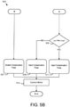
- FIGS. 5A-C are schematic flow chart diagrams of a high frequency injection transition disturbance elimination method 500.
- the method 500 determines the compensation pulse voltages 175 and injects the sum of the HFI compensation pulse 141 and HFI voltage 171 into the current regulator voltage output signal 135 for a compensation PWM cycle 148 to settle the HFI current 144.
- the method 500 may be performed by the processor 405 and/or hardware components.
- the processor 405 is referred to, but hardware components may also perform the functions.
- the method 500 starts and the processor 405 determines 501 whether the current value HFI enable in signal HFI_ENBL_IN NOW 168 is ON, indicating the current use of HFI. If the current value HFI enable in signal HFI_ENBL_IN NOW 168 is not ON, the processor 405 determines 521 whether the previous value HFI enable in signal HFI_ENBL_INP REV 168 was ON. If the current value HFI enable in signal HFI_ENBL_IN NOW 168 is not ON and the previous value HFI enable in signal HFI_ENBL_INP REV 168 was ON, there is no HFI transition 201 in path D. The processor 405 may direct no HFI transition. In addition, the processor 405 may detect no HFI transition.
- the processor 405 may disable 529 the HFI compensation pulse 141. In one embodiment, the processor 405 sets the HFI enable out signal HFI ENBL OUT 169 to OFF.
- the alpha compensation pulse voltage V ⁇ h_comp 175a may be zero.
- the beta compensation pulse voltage V ⁇ h_comp 175b also may be zero.
- the processor 405 may determine 523 whether the HFI compensation pulse 141 happens before the HFI transition 201 as shown in Figure 3A or after the HFI 201 as shown in Figure 3B . If the transition cycle 201 is the last PWM cycle 148a in step 523, the processor 405 determines the compensation pulse voltages 175 for the HFI compensation pulse 141 and injects 527 a sum of the HFI compensation pulse 141 and the HFI voltage 171 into the current regulator voltage output signal 135.
- the alpha compensation pulse voltage V ⁇ h _ comp 175a may be calculated using Equation 8.
- the beta compensation pulse voltage V ⁇ h_comp 175b may be calculated using Equation 9.
- the processor 405 sets the HFI enable out signal HFI_ENBL _OUT 169 to OFF.
- the processor 405 determines the compensation pulse voltages 175 for the HFI compensation pulse 141 and injects 525 a sum of the HFI compensation pulse 141 and the HFI voltage 171 into the current regulator voltage output signal 135.
- the alpha compensation pulse voltage V ⁇ h_comp 175a may be calculated using Equation 2.
- the beta compensation pulse voltage V ⁇ h_comp 175b may be calculated using Equation 3.
- the processor 405 sets the HFI enable out signal HFI_ENBL_OUT 169 to ON.
- the processor 405 may direct the HFI transition.
- the processor 405 detect the HFI transition.
- the processor 405 determines 503 whether the previous value HFI enable in signal HFI_ENBL_INP REV 168 was OFF. If the current value HFI enable in signal HFI_ENBL_IN NOW 168 is ON and the previous value HFI enable in signal HFI_ENBL_INP REV 168 was not OFF, there is no HFI transition 201 detected in path B.
- the processor 405 may direct no HFI transition. In addition, the processor 405 may detect no HFI transition.
- the processor 405 may disable 507 the HFI compensation pulse 141. In one embodiment, the processor 405 sets the HFI enable out signal HFI_ENBL_OUT 169 to ON.
- the alpha compensation pulse voltage V ⁇ h_comp 175a and the beta compensation pulse voltage V ⁇ h _ camp 175b may be zero.
- the processor 405 determines 505 whether the transition cycle 201 is a last PWM cycle 148a before the transition cycle 201 as shown in Figure 3A . If the transition cycle 201 is the last PWM cycle 148a in step 505, the processor 405 determines the compensation pulse voltages 175 for the HFI compensation pulse 141 and injects 511 a sum of the HFI compensation pulse 141 and the HFI voltage 171 into the current regulator voltage output signal 135.
- the alpha compensation pulse voltage V ⁇ h_comp 175a may be calculated using Equation 2.
- the beta compensation pulse voltage V ⁇ h _ comp 175b may be calculated using Equation 3.
- the processor 405 sets the HFI enable out signal HFI ENBL OUT 169 to OFF.
- the processor 405 determines the compensation pulse voltages 175 for the HFI compensation pulse 141 and injects 509 a sum of the HFI compensation pulse 141 and the HFI voltage 171 into the current regulator voltage output signal 135.
- the alpha compensation pulse voltage V ⁇ h_comp 175a may be calculated using Equation 2.
- the beta compensation pulse voltage V ⁇ h_comp 175b may be calculated using Equation 3.
- the processor 405 sets the HFI enable out signal HFI_ENBL_OUT 169 to ON.
- the processor 405 may direct the HFI transition.
- the processor 405 detect the HFI transition.
- the processor 405 may control 513 the motor 101 with or without HFI and the method 500 ends.
- FIG. 6A is experimental waveforms of an off to on HFI transition without the HFI compensation pulse 141.
- a control output voltage 125 a motor angle estimate 114, a reconstructed stationary reference frame alpha-axis current 1 ⁇ 131a, and a measured drive phase A current 143a are shown.
- drive current 143 takes time to settle, reducing the accuracy of the estimated position information 114, resulting in inaccurate control of the motor 101.
- Figure 6B is waveforms of an off to on HFI transition with the HFI compensation pulse 141.
- a measured current 142, control output voltage V d 125, motor angle estimate 114, a reconstructed stationary reference frame alpha-axis current I ⁇ 131a, and a measured drive phase A current 143a of Fig. 1B are shown for the off to on HFI transition.
- the measured current 142 is close up zoom view of the measured drive phase A current 143a about the HFI transition 201. Because of the injection of the HFI compensation pulse 141, the reconstructed stationary reference frame alpha-axis current I ⁇ 131a and the measured drive phase A current 143a settle to a steady state almost instantaneously. As a result, the glitch 203 during the HFI transition 201 is absent.
- FIG. 6C is experimental waveforms of an on to off HFItransition without the HFI compensation pulse 141.
- a control output voltage 125, a motor angle estimate 114, a reconstructed stationary reference frame alpha-axis current I ⁇ 131a, and a measured drive phase A current 143a are shown.
- drive current 143 takes time to settle, reducing the accuracy of the estimated position information 114, resulting in inaccurate control of the motor 101.
- Figure 6D is waveforms of an on to off HFI transition with the HFI compensation pulse 141.
- the measured current 142, drive current 143, control output voltage V d 125, motor angle estimate 114, a reconstructed stationary reference frame alpha-axis current I ⁇ 131, and a measured drive phase A current 143a of Fig. 1B are shown for the on to off HFI transition.
- the reconstructed stationary reference frame alpha-axis current I ⁇ 131a, and the drive phase A current 143a settle to steady state almost instantaneously.
- the glitch 203 during the HFI transition 201 is absent.
- a motor system 100 may employ HFI to eliminate the cost of a position sensor for determining the position of the rotor 105 in the motor 101.
- the HFI alpha-axis current I ⁇ h 176a and the HFI beta-axis current I ⁇ h 176b includes the position information of the HFI voltage 171 from which the angular velocity estimate ⁇ 113 and the motor angle estimate 114 are determined.
- the drive current 143 in Figure 2 takes time to stabilize, reducing the accuracy of the estimated position information 114 and reconstructed stationary reference frame alpha-axis current 131, thus injecting disturbance into current regulator 110 in Fig 1B .
- the embodiments detect the HFI transition 201 of the HFI voltage 171 for the motor 101 and determine the compensation pulse voltages 175a-b for the HFI compensation pulse 141.
- the embodiments further inject a sum of the HFI compensation pulse 141 and the HFI voltage 171 into the current regulator voltage output signal 135 for a compensation PWM cycle 148.
- the HFI compensation pulse 141 settles the HFI current 144 to a steady state almost instantaneously. As a result, the efficacy of the position determination using HFI is enhanced.
Landscapes
- Engineering & Computer Science (AREA)
- Power Engineering (AREA)
- Control Of Ac Motors In General (AREA)
Abstract
Description
- The subject matter disclosed herein relates to high frequency injection transition disturbance elimination for salient pole electric machines.
- An apparatus for high frequency injection (HFI) transition disturbance elimination is disclosed. The apparatus includes a processor and a memory storing code executable by the processor. The processor directs an HFI transition for a motor. The processor determines compensation pulse voltages for an HFI compensation pulse. The processor further injects a sum of the HFI compensation pulse and an HFI voltage into a current regulator voltage output signal for a transition Pulse Width Modulation (PWM) cycle. The HFI compensation pulse settles an HFI current to a steady state.
- A method for HFI transition disturbance elimination is also disclosed. The method directs an HFI transition for a motor. The method determines compensation pulse voltages for an HFI compensation pulse. The method further injects a sum of the HFI compensation pulse and an HFI voltage into a current regulator voltage output signal for a compensation PWM cycle. The HFI compensation pulse settles an HFI current to a steady state.
- A computer program product for HFI transition disturbance elimination is also disclosed. A processor directs an HFI transition for a motor. The processor determines compensation pulse voltages for an HFI compensation pulse. The processor further injects a sum of the HFI compensation pulse and an HFI voltage into a current regulator voltage output signal for a compensation PWM cycle. The HFI compensation pulse settles an HFI current to a steady state.
- In order that the advantages of the embodiments of the invention will be readily understood, a more particular description of the embodiments briefly described above will be rendered by reference to specific embodiments that are illustrated in the appended drawings. Understanding that these drawings depict only some embodiments and are not therefore to be considered to be limiting of scope, the embodiments will be described and explained with additional specificity and detail through the use of the accompanying drawings, in which:
-
Figure 1A is a schematic block diagram of an electric motor control system according to an embodiment; -
Figure 1B is a schematic block diagram of an electric motor control system according to an embodiment; -
Figure 1C is a schematic block diagram of an HFI angle and speed estimator according to an embodiment; -
Figure 2A is graphs of HFI transition from off to on without a compensation voltage pulse voltage according to an embodiment; -
Figure 2B is graphs of HFI transition from on to off without a compensation voltage pulse voltage according to an embodiment; -
Figure 3A is a graph of PWM cycles, where compensation pulse is injected before transition occurs, according to an embodiment; -
Figure 3B is a graph of PWM cycles, where compensation pulse is injected after transition occurs, according to an alternate embodiment; -
Figure 4A is graphs of HFI transition from off to on with the proposed compensation voltage pulse scheme, according to an embodiment; -
Figure 4B is graphs of HFI transition from on to off with the proposed compensation voltage pulse scheme, according to an embodiment; -
Figure 5A-C are schematic flow chart diagrams of an HFI transition disturbance elimination method; -
Figure 6A is experimental waveforms of an off to on HFI transition without compensation scheme according to an embodiment; -
Figure 6B is experimental waveforms of an off to on HFI transition with compensation scheme according to an embodiment; -
Figure 6C is experimental waveforms of an on to off HFI transition without compensation scheme according to an embodiment; and -
Figure 6D is experimental waveforms of an on to off HFI transition with compensation scheme according to an embodiment. - Reference throughout this specification to "one embodiment," "an embodiment," or similar language means that a particular feature, structure, or characteristic described in connection with the embodiment is included in at least one embodiment. Thus, appearances of the phrases "in one embodiment," "in an embodiment," and similar language throughout this specification may, but do not necessarily, all refer to the same embodiment, but mean "one or more but not all embodiments" unless expressly specified otherwise. The terms "including," "comprising," "having," and variations thereof mean "including but not limited to" unless expressly specified otherwise An enumerated listing of items does not imply that any or all of the items are mutually exclusive and/or mutually inclusive, unless expressly specified otherwise The terms "a," "an," and "the" also refer to "one or more" unless expressly specified otherwise. The term "and/or" indicates embodiments of one or more of the listed elements, with "A and/or B" indicating embodiments of element A alone, element B alone, or elements A and B taken together.
- Furthermore, the described features, advantages, and characteristics of the embodiments may be combined in any suitable manner. One skilled in the relevant art will recognize that the embodiments may be practiced without one or more of the specific features or advantages of a particular embodiment. In other instances, additional features and advantages may be recognized in certain embodiments that may not be present in all embodiments.
- These features and advantages of the embodiments will become more fully apparent from the following description and appended claims or may be learned by the practice of embodiments as set forth hereinafter. As will be appreciated by one skilled in the art, aspects of the present invention may be embodied as a system, method, and/or computer program product. Accordingly, aspects of the present invention may take the form of an entirely hardware embodiment, an entirely software embodiment (including firmware, resident software, micro-code, etc.) or an embodiment combining software and hardware aspects that may all generally be referred to herein as a "circuit," "module," or "system." Furthermore, aspects of the present invention may take the form of a computer program product embodied in one or more computer readable medium(s) having program code embodied thereon.
- Many of the functional units described in this specification have been labeled as modules, in order to more particularly emphasize their implementation independence. For example, a module may be implemented as a hardware circuit comprising custom VLSI circuits or gate arrays, off-the-shelf semiconductors such as logic chips, transistors, or other discrete components. A module may also be implemented in programmable hardware devices such as field programmable gate arrays, programmable array logic, programmable logic devices or the like.
- Modules may also be implemented in software for execution by various types of processors. An identified module of program code may, for instance, comprise one or more physical or logical blocks of computer instructions which may, for instance, be organized as an object, procedure, or function. Nevertheless, the executables of an identified module need not be physically located together but may comprise disparate instructions stored in different locations which, when joined logically together, comprise the module and achieve the stated purpose for the module.
- Indeed, a module of program code may be a single instruction, or many instructions, and may even be distributed over several different code segments, among different programs, and across several memory devices. Similarly, operational data may be identified and illustrated herein within modules and may be embodied in any suitable form and organized within any suitable type of data structure. The operational data may be collected as a single data set or may be distributed over different locations including over different storage devices, and may exist, at least partially, merely as electronic signals on a system or network. Where a module or portions of a module are implemented in software, the program code may be stored and/or propagated on in one or more computer readable medium(s).
- The computer readable medium may be a tangible computer readable storage medium storing the program code. The computer readable storage medium may be, for example, but not limited to, an electronic, magnetic, optical, electromagnetic, infrared, holographic, micromechanical, or semiconductor system, apparatus, or device, or any suitable combination of the foregoing.
- More specific examples of the computer readable storage medium may include but are not limited to a portable computer diskette, a hard disk, a random access memory (RAM), a read-only memory (ROM), an erasable programmable read-only memory (EPROM or Flash memory), a portable compact disc read-only memory (CD-ROM), a digital versatile disc (DVD), an optical storage device, a magnetic storage device, a holographic storage medium, a micromechanical storage device, or any suitable combination of the foregoing. In the context of this document, a computer readable storage medium may be any tangible medium that can contain, and/or store program code for use by and/or in connection with an instruction execution system, apparatus, or device.
- The computer readable medium may also be a computer readable signal medium. A computer readable signal medium may include a propagated data signal with program code embodied therein, for example, in baseband or as part of a carrier wave. Such a propagated signal may take any of a variety of forms, including, but not limited to, electrical, electro-magnetic, magnetic, optical, or any suitable combination thereof A computer readable signal medium may be any computer readable medium that is not a computer readable storage medium and that can communicate, propagate, or transport program code for use by or in connection with an instruction execution system, apparatus, or device. Program code embodied on a computer readable signal medium may be transmitted using any appropriate medium, including but not limited to wireline, optical fiber, Radio Frequency (RF), or the like, or any suitable combination of the foregoing
- In one embodiment, the computer readable medium may comprise a combination of one or more computer readable storage mediums and one or more computer readable signal mediums. For example, program code may be both propagated as an electro-magnetic signal through a fiber optic cable for execution by a processor and stored on RAM storage device for execution by the processor.
- Program code for carrying out operations for aspects of the present invention may be written in any combination of one or more programming languages, including an object oriented programming language such as Python, Ruby, R, Java, Java Script, Smalltalk, C++, C sharp, Lisp, Clojure, PHP or the like and conventional procedural programming languages, such as the "C" programming language or similar programming languages. The program code may execute entirely on the user's computer, partly on the user's computer, as a stand-alone software package, partly on the user's computer and partly on a remote computer or entirely on the remote computer or server. In the latter scenario, the remote computer may be connected to the user's computer through any type of network, including a local area network (LAN) or a wide area network (WAN), or the connection may be made to an external computer (for example, through the Internet using an Internet Service Provider). The computer program product may be shared, simultaneously serving multiple customers in a flexible, automated fashion.
- The computer program product may be integrated into a client, server and network environment by providing for the computer program product to coexist with applications, operating systems and network operating systems software and then installing the computer program product on the clients and servers in the environment where the computer program product will function. In one embodiment software is identified on the clients and servers including the network operating system where the computer program product will be deployed that are required by the computer program product or that work in conjunction with the computer program product. This includes the network operating system that is software that enhances a basic operating system by adding networking features.
- Furthermore, the described features, structures, or characteristics of the embodiments may be combined in any suitable manner. In the following description, numerous specific details are provided, such as examples of programming, software modules, user selections, network transactions, database queries, database structures, hardware modules, hardware circuits, hardware chips, etc., to provide a thorough understanding of embodiments. One skilled in the relevant art will recognize, however, that embodiments may be practiced without one or more of the specific details, or with other methods, components, materials, and so forth. In other instances, well-known structures, materials, or operations are not shown or described in detail to avoid obscuring aspects of an embodiment.
- The embodiments may transmit data between electronic devices. The embodiments may further convert the data from a first format to a second format, including converting the data from a non-standard format to a standard format and/or converting the data from the standard format to a non-standard format. The embodiments may modify, update, and/or process the data. The embodiments may store the received, converted, modified, updated, and/or processed data. The embodiments may provide remote access to the data including the updated data. The embodiments may make the data and/or updated data available in real time. The embodiments may generate and transmit a message based on the data and/or updated data in real time.
- Aspects of the embodiments are described below with reference to schematic flowchart diagrams and/or schematic block diagrams of methods, apparatuses, systems, and computer program products according to embodiments of the invention. It will be understood that each block of the schematic flowchart diagrams and/or schematic block diagrams, and combinations of blocks in the schematic flowchart diagrams and/or schematic block diagrams, can be implemented by program code. The program code may be provided to a processor of a general purpose computer, special purpose computer, sequencer, or other programmable data processing apparatus to produce a machine, such that the instructions, which execute via the processor of the computer or other programmable data processing apparatus, create means for implementing the functions/acts specified in the schematic flowchart diagrams and/or schematic block diagrams block or blocks.
- The program code may also be stored in a computer readable medium that can direct a computer, other programmable data processing apparatus, or other devices to function in a particular manner, such that the instructions stored in the computer readable medium produce an article of manufacture including instructions which implement the function/act specified in the schematic flowchart diagrams and/or schematic block diagrams block or blocks.
- The program code may also be loaded onto a computer, other programmable data processing apparatus, or other devices to cause a series of operational steps to be performed on the computer, other programmable apparatus or other devices to produce a computer implemented process such that the program code which executed on the computer or other programmable apparatus provide processes for implementing the functions/acts specified in the flowchart and/or block diagram block or blocks.
- The schematic flowchart diagrams and/or schematic block diagrams in the Figures illustrate the architecture, functionality, and operation of possible implementations of apparatuses, systems, methods and computer program products according to various embodiments of the present invention. In this regard, each block in the schematic flowchart diagrams and/or schematic block diagrams may represent a module, segment, or portion of code, which comprises one or more executable instructions of the program code for implementing the specified logical function(s).
- It should also be noted that, in some alternative implementations, the functions noted in the block may occur out of the order noted in the Figures. For example, two blocks shown in succession may, in fact, be executed substantially concurrently, or the blocks may sometimes be executed in the reverse order, depending upon the functionality involved. Other steps and methods may be conceived that are equivalent in function, logic, or effect to one or more blocks, or portions thereof, of the illustrated Figures.
- Although various arrow types and line types may be employed in the flowchart and/or block diagrams, they are understood not to limit the scope of the corresponding embodiments. Indeed, some arrows or other connectors may be used to indicate only the logical flow of the depicted embodiment. For instance, an arrow may indicate a waiting or monitoring period of unspecified duration between enumerated steps of the depicted embodiment. It will also be noted that each block of the block diagrams and/or flowchart diagrams, and combinations of blocks in the block diagrams and/or flowchart diagrams, can be implemented by special purpose hardware-based systems that perform the specified functions or acts, or combinations of special purpose hardware and program code.
- The description of elements in each figure may refer to elements of proceeding figures. Like numbers refer to like elements in all figures, including alternate embodiments of like elements.
-
Figure 1A is a schematic block diagram of an electricmotor control system 100. Thesystem 100 drives amotor 101 in response to aspeed command 102. Themotor 101 may be asalient motor 101. The electricmotor control system 100 includes a plurality of function blocks that may be performed by hardware components, code executed by a processor, or combinations thereof. - In the depicted embodiment, a
converter 21 generates a drive current Ia, Ib, Ic 143a-c that drives themotor 101 from a DCbus voltage V DC 167. Theconverter 21 may be afull bridge converter 21 comprising acapacitor 15 and a plurality of insulated gate bipolar transistors (IGBT) 11. TheIGBT 11 may be driven bygate signals 17 generated by aPWM driver 13. ThePWM driver 13 is controlled by aprocessor 405 executing code stored on amemory 410. An analog to digital (A/D)converter 19 may provide the drive current 143a-c to theprocessor 405. - The electric
motor control system 100 does not include a position sensor. Instead a High Frequency Injection (HFI) voltage is injected to enable the extraction of position information. The position information may be extracted at low speed. The position information enables control of themotor 101 without a position sensor. -
Figure 1B is a schematic block diagram of themotor system 100. The depicted embodiment may employ pulse voltage injection of an HFI voltage, wherein the HFI voltage is a sinusoidal voltage injection in d-q axis synchronous reference frame. Alternatively, the HFI voltage may be a sinusoidal voltage injection in alpha-beta stationary reference frame or a square wave voltage injection in d-q axis synchronous reference frame. Thesystem 100 drives themotor 101 in response to thespeed command 102. Themotor system 100 includes a plurality of function blocks that may be performed by hardware components, code executed by a processor, or combinations thereof. - In the depicted embodiment, an angular
velocity estimate ω 113 is subtracted from aspeed command 102 and received by aspeed regulator function 104. Thespeed regulator 104 generates atorque command 106. - A Maximum Torque Per Ampere (MTPA)/
Flux Weakening function 108 receives thetorque command 106 along with the angularvelocity estimate ω 113 and the DCbus voltage V DC 167 and generates a D-axis current command Id ∗ 121 and a Q-axiscurrent command I q ∗ 123. Acurrent regulator 110 receives the D-axis current command Id ∗ 121 and the Q-axis current command Iq ∗ 123 and generates a D-axis controloutput voltage V d ∗125 and a Q-axis controloutput voltage V q ∗ 126. - A synchronous to
stationary transformation function 112 receives the D-axis controloutput voltage V d ∗125 and the Q-axis controloutput voltage V q ∗ 126 along with amotor angle estimate 114 and generates an alpha current regulator voltage output signal Vα 135a and a betavoltage signal V β 135b. The alpha current regulator voltage output signal Vα 135a is summed with a corresponding HFIalpha voltage V α_HFI 137a as areference voltage 130a. The beta current regulator voltageoutput signal V β 135b is summed with a corresponding HFI betavoltage signal V β_HFI 137b as areference voltage 130b. Thereference voltages 130a-b drive thePWM modulator 124. The addition of the HFIalpha voltage V α_HFI 137a and the HFI betavoltage signal V β_HFI 137b supports the extraction of the angularvelocity estimate ω 113 and the motorangle estimate θ 114. - As shown, the
PWM modulator 124 controls theinverter 116 to output acommand voltage 12, which drives themotor 101 with a drive current 143a-c. The drive current 143a-c is measured by current sensor of an HFI harmonic current and fundamentalcurrent separation function 122. The HFI harmonic current and fundamentalcurrent separation function 122 separates the HFI harmonic current from the fundamental frequency current of the drive current 143. The HFI harmonic current and fundamentalcurrent separation function 122 outputs in a high frequency domain HFI alpha-axis current Iαh 176a and an HFI beta-axis current Iβh 176b from the drive current 143a-c. In addition, the HFI harmonic current and fundamentalcurrent separation function 122 outputs in a fundamental frequency domain of a stationary reference frame alpha-axis current Iα 131a and a beta-axis current Iβ 131b based on the drive current 143a-c. The HFI angle andspeed estimator function 118 receives the HFI alpha-axis current Iαh 176a and the HFI beta-axis current Iβh 176b and generates the angularvelocity estimate ω 113, themotor angle estimate 114. It also outputs a final HFI injectionalpha voltage V α_HFI 137a, and a final HFI injection betavoltage signal V β_HFI 137b. The HFI angle andspeed estimator function 118 is described in more detail inFigure 1B . - A stationary to
synchronous transformation function 120 generates the D-axis current Id 127 and the Q-axis current Iq 129 from the alpha current Iα 131a and the beta current Iβ 131b. -
Figure 1C is a schematic block diagram of the HFI angle andspeed estimator 118 ofFigures 1A-B . The high frequency injection angle andspeed estimator 118 includes a plurality of function blocks that may be performed by hardware components, code executed by a processor, or combinations thereof. In the depicted embodiment, the high frequency injection angle andspeed estimator 118 include an HFIcompensation logic controller 161 and an HFI voltage generator and angle estimator128. - The HFI injection frequency domain HFI alpha-axis current Iαh 176a and the HFI injection frequency domain HFI beta-axis current Iβh 176b contains the rotor position information of the
motor 101 and are used by the angle andspeed generator function 165 to generate the angularvelocity estimate ω 113 and themotor angle estimate 114. - The HFI
injection voltage generator 163 receives an HFI referencevoltage magnitude V h 174, an HFIvoltage frequency ω h 172 and an initial phase offsetϕ 173 and calculates analpha HFI voltage 171a and abeta HFI voltage 171b. In one embodiment, the alphaHFI voltage V αh 171a and the betaHFI voltage V βh 171b are calculated using Equation 1, wherein t is time.

- The Salient Pole Machine High Frequency Domain Voltage Equation can be written as shown in Equation 2:

- Where


- Using Equation 1 into Equation 2, and the high frequency current is deducted as,

- Here, only the HFI transition from off to on is calculated as an example. For the case when HFI transition from on to off, the similar equation can be deducted.
- When HFI off to on transition occurs, t=0, the above equation is simplified as,

- Where [I αh0, I βh0] is the initial steady state high frequency domain HFI alpha-axis current 176a and frequency domain HFI beta-axis current 176b. θ 0 is the rotor position when at t=0. The initial expected steady state stator flux can be calculated as,

- If no additional control is implemented, the high frequency domain initial flux is,

- Thus, a compensation voltage pulse is injected to accelerate the initial flux from zero in equation 6 to its steady state in equation 5 within very short time period defined as T as shown in Equation 7,

- The HFI compensation voltage generator 162 also receives the
injection voltage V h 174, theinjection frequency ω h 172 and the phase offsetϕ 173 and calculates an alpha compensationpulse voltage V ah_comp 175a and a beta compensationpulse voltage V βh_comp 175b of a compensation pulse voltage 175. The alpha compensationpulse voltage V αh_comp 175a and the beta compensationpulse voltage V βh_comp 175b are calculated using Equations 2 and 3. - By substituting the initial steady state flux in equation 7 with the predicted initial flux value calculated using equation 5 and equation 4, the final compensation voltage pulse is calculated as:


- The HFI angle and
speed estimator 118 is enabled by an HFI enable insignal HFI_ENBL_IN 168. The current ISR step HFI_ENBL_IN is named HFI_ENBL_INNOW, while the previous ISR step HFI_ENBL_IN is named HFI_ENBL_INPREV. In response to the HFI enable insignal 168 being asserted, an HFIcompensation logic controller 161 generates an HFI enable outsignal HFI_ENBL_OUT 169 that enables the HFIinjection voltage generator 163 of theHFI 128 and an HFI compensation enablesignal HFI_COMP_ENBL 170 that enables the HFI compensation voltage generator 162 of theHFI 128. - If the HFI enable in signal
HFI ENBL IN 168 is enabled, the HFI enable outsignal HFI_ENBL_OUT 169 enables the HFIinjection voltage generator 163 to generate the alphaHFI voltage V αh171a and the betaHFI voltage V βh 171b waveforms. - Unfortunately, when the HFI
injection voltage generator 163 is transitioned ON or OFF, the addition of the HFI voltage 137 causes a temporary transition disturbance in the control system. The embodiments inject a compensation pulse comprised of the alpha compensationpulse voltage V αh_comp 175a and the beta compensationpulse voltage V βh_comp 175b during a transition of the alphaHFI voltage V αh171a and the betaHFI voltage V βh 171b waveforms from OFF to ON or from ON to OFF. HFI compensation enablesignal HFI_COMP_ENBL 170 enables the HFI compensation voltage generator 162 to generate thecompensation pulse voltages 175a-b for the compensation pulse calculated in Equations 8 and 9. The sum of the alphaHFI voltage V αh171a and the alpha compensationpulse voltage V αh_comp 175a generates the final HFI injectedalpha voltage V α_HFI 137a. The sum of the betaHFI voltage V βh 171b and the beta compensationpulse voltage V βh_comp 175b generates the final HFI injected betavoltage signal V β_HFI 137b. -
Figure 2A isgraphs 202a-c of high frequency injection waveforms.Graph 202a shows theHFIvoltage 171 before and after an OFF toON HFI transition 201.Graph 202b shows the drive output current 143a-c before and after theHFI transition 201. As shown in 202c, there is a delay in the HFI component of the drive current 143a-c settling, causing offsets 149. The delay of settling of HFI current in 202c causes the offset 149 in 202b. The delay causes a disturbance in the accuracy of the motorangle estimate θ 114 and the angularvelocity estimate ω 113, and the detected reconstructed stationary reference frame current 131a-b. The embodiments determine the compensation pulse voltages 175 for a compensation pulse that is injected with the HFI voltage 137 into the current regulator voltage output signal 135 to settle the HFI current 144 to a steady state almost instantaneously. -
Figure 2B isgraphs 204a-c of high frequency injection waveforms.Graph 204a shows theHFI voltage 171 before and after an ON toOFF HFI transition 201.Graph 204b shows the drive output current 143a-c before and after theHFI transition 201. As shown, there is a delay in the HFI component of the drive current 143a-c settling, resulting inoffsets 149. The delay of settling of the HFI current in 204c causes the offset 149 in 204b. The delay causes a disturbance in the accuracy of the motorangle estimate θ 114 and the angularvelocity estimate ω 113, and the detected reconstructed stationary reference frame current 131a-b. -
Figure 3A is a graph of PWM cycles 148 before and after anHFI transition 201. In the depicted embodiment, anHFI compensation pulse 141 with the compensation pulse voltages 175 is generated and summed with theHFI voltage 171 into the current regulator voltage output signal 135 for the PWM cycle 148 before the HFI transition. Thepulse 141 can be aligned to the rising period of PWMcarrier counter cycle 148a or the falling period of PWMcarrier counter cycle 148a, or the middle of the PWMcarrier counter cycle 148a -
Figure 3B is a graph of PWM cycles 148 before and after anHFI transition 201. In the depicted embodiment, theHFI compensation pulse 141 with the compensation pulse voltages 175 is generated and summed with theHFI voltage 171 into the current regulator voltage output signal 135 for the PWM cycle 148 after theHFI transition 201. Thepulse 141 may be aligned to the rising period of PWMcarrier counter cycle 148b or the falling period of PWMcarrier counter cycle 148b, or the middle of the PWMcarrier counter cycle 148b. -
Figure 4A isgraphs 206a-d of high frequency injection waveforms.Graph 206a shows theHFI voltage 171 before and after an OFF toON HFI transition 201.Graph 206b shows the drive current 143a-c before and after theHFI transition 201. The injection of theHFI compensation pulse 141 ofgraph 206d mitigates the delays in the HFI component of the drive current 143a-c settling shown inFigure 2A and mitigates theoffsets 149, resulting in the HFI current 144 settling to steady state. The HFI current 144 shown ingraph 206c may settle to steady state in less than a machine time constant for themotor 101. The machine time constant may be the inductance for themotor 101 divided by the resistance for themotor 101. -
Figure 4B isgraphs 208a-d of high frequency injection waveforms.Graph 208a shows theHFI voltage 171 before and after an ON toOFF HFI transition 201.Graph 208b shows the drive current 143a-c before and after theHFI transition 201. The injection of theHFI compensation pulse 141 ofgraph 208d mitigates the delays in the HFI component of the drive current 143a-c settling shown inFigure 2B and mitigates theoffsets 149, resulting in the HFI current 144 settling to steady state. The HFI current 144 shown ingraph 208c may settle to steady state in less than the machine time constant for themotor 101. -
Figure 5A-C are schematic flow chart diagrams of a high frequency injection transitiondisturbance elimination method 500. Themethod 500 determines the compensation pulse voltages 175 and injects the sum of theHFI compensation pulse 141 andHFI voltage 171 into the current regulator voltage output signal 135 for a compensation PWM cycle 148 to settle the HFI current 144. Themethod 500 may be performed by theprocessor 405 and/or hardware components. For clarity, theprocessor 405 is referred to, but hardware components may also perform the functions. - The
method 500 starts and theprocessor 405 determines 501 whether the current value HFI enable insignal HFI_ENBL_IN NOW 168 is ON, indicating the current use of HFI. If the current value HFI enable insignal HFI_ENBL_IN NOW 168 is not ON, theprocessor 405 determines 521 whether the previous value HFI enable insignal HFI_ENBL_INP REV 168 was ON. If the current value HFI enable insignal HFI_ENBL_IN NOW 168 is not ON and the previous value HFI enable insignal HFI_ENBL_INP REV 168 was ON, there is noHFI transition 201 in path D. Theprocessor 405 may direct no HFI transition. In addition, theprocessor 405 may detect no HFI transition. Theprocessor 405 may disable 529 theHFI compensation pulse 141. In one embodiment, theprocessor 405 sets the HFI enable out signalHFI ENBL OUT 169 to OFF. The alpha compensationpulse voltage V αh_comp 175a may be zero. The beta compensationpulse voltage V βh_comp 175b also may be zero. - If the current value HFI enable in
signal HFI_ENBL_IN NOW 168 is not ON and the previous value HFI enable insignal HFI_ENBL_INP REV 168 was ON, an HFI On toOFF transition 201 is detected and/or directed. Theprocessor 405 may determine 523whether theHFI compensation pulse 141 happens before theHFI transition 201 as shown inFigure 3A or after theHFI 201 as shown inFigure 3B . If thetransition cycle 201 is thelast PWM cycle 148a instep 523, theprocessor 405 determines the compensation pulse voltages 175 for theHFI compensation pulse 141 and injects 527 a sum of theHFI compensation pulse 141 and theHFI voltage 171 into the current regulator voltage output signal 135. The alpha compensationpulse voltage V αh_comp 175a may be calculated using Equation 8. The beta compensationpulse voltage V βh_comp 175b may be calculated using Equation 9. In one embodiment, theprocessor 405 sets the HFI enable outsignal HFI_ENBL _OUT 169 to OFF. - If the
transition cycle 201 is not thelast PWM cycle 148a instep 523 as shown inFigure 3B , theprocessor 405 determines the compensation pulse voltages 175 for theHFI compensation pulse 141 and injects 525 a sum of theHFI compensation pulse 141 and theHFI voltage 171 into the current regulator voltage output signal 135. The alpha compensationpulse voltage V αh_comp 175a may be calculated using Equation 2. The beta compensationpulse voltage V βh_comp 175b may be calculated using Equation 3. In one embodiment, theprocessor 405 sets the HFI enable outsignal HFI_ENBL_OUT 169 to ON. Theprocessor 405 may direct the HFI transition. In addition, theprocessor 405 detect the HFI transition. - If the current value HFI enable in
signal HFI_ENBL_IN NOW 168 is ON, theprocessor 405 determines 503 whether the previous value HFI enable insignal HFI_ENBL_INP REV 168 was OFF. If the current value HFI enable insignal HFI_ENBL_IN NOW 168 is ON and the previous value HFI enable insignal HFI_ENBL_INP REV 168 was not OFF, there is noHFI transition 201 detected in path B. Theprocessor 405 may direct no HFI transition. In addition, theprocessor 405 may detect no HFI transition. Theprocessor 405 may disable 507 theHFI compensation pulse 141. In one embodiment, theprocessor 405 sets the HFI enable outsignal HFI_ENBL_OUT 169 to ON. The alpha compensationpulse voltage V αh_comp 175a and the beta compensationpulse voltage V βh_camp 175b may be zero. - If the current value HFI enable in
signal HFI_ENBL_IN NOW 168 is ON and the previous value HFI enable insignal HFI_ENBL_INP REV 168 was OFF instep 503, an OFF toON HFI transition 201 is detected and/or directed. Theprocessor 405 determines 505 whether thetransition cycle 201 is alast PWM cycle 148a before thetransition cycle 201 as shown inFigure 3A . If thetransition cycle 201 is thelast PWM cycle 148a instep 505, theprocessor 405 determines the compensation pulse voltages 175 for theHFI compensation pulse 141 and injects 511 a sum of theHFI compensation pulse 141 and theHFI voltage 171 into the current regulator voltage output signal 135. The alpha compensationpulse voltage V αh_comp 175a may be calculated using Equation 2. The beta compensationpulse voltage V βh_comp 175b may be calculated using Equation 3. In one embodiment, theprocessor 405 sets the HFI enable out signalHFI ENBL OUT 169 to OFF. - If the
transition cycle 201 is not thelast PWM cycle 148a instep 505 as shown inFigure 3B , theprocessor 405 determines the compensation pulse voltages 175 for theHFI compensation pulse 141 and injects 509 a sum of theHFI compensation pulse 141 and theHFI voltage 171 into the current regulator voltage output signal 135. The alpha compensationpulse voltage V αh_comp 175a may be calculated using Equation 2. The beta compensationpulse voltage V βh_comp 175b may be calculated using Equation 3. In one embodiment, theprocessor 405 sets the HFI enable outsignal HFI_ENBL_OUT 169 to ON. Theprocessor 405 may direct the HFI transition. In addition, theprocessor 405 detect the HFI transition. - The
processor 405 may control 513 themotor 101 with or without HFI and themethod 500 ends. -
Figure 6A is experimental waveforms of an off to on HFI transition without theHFI compensation pulse 141. A control output voltage 125 amotor angle estimate 114, a reconstructed stationary reference frame alpha-axis current 1α 131a, and a measured drive phase A current 143a are shown. At theHFI transition 201, drive current 143 takes time to settle, reducing the accuracy of the estimatedposition information 114, resulting in inaccurate control of themotor 101. As a result, there is aglitch 203 in thecontrol output voltage 125. -
Figure 6B is waveforms of an off to on HFI transition with theHFI compensation pulse 141. A measured current 142, controloutput voltage V d 125,motor angle estimate 114, a reconstructed stationary reference frame alpha-axis current Iα 131a, and a measured drive phase A current 143a ofFig. 1B are shown for the off to on HFI transition. The measured current 142 is close up zoom view of the measured drive phase A current 143a about theHFI transition 201. Because of the injection of theHFI compensation pulse 141, the reconstructed stationary reference frame alpha-axis current Iα 131a and the measured drive phase A current 143a settle to a steady state almost instantaneously. As a result, theglitch 203 during theHFI transition 201 is absent. -
Figure 6C is experimental waveforms of an on to off HFItransition without theHFI compensation pulse 141. Acontrol output voltage 125, amotor angle estimate 114, a reconstructed stationary reference frame alpha-axis current Iα 131a, and a measured drive phase A current 143a are shown. At theHFI transition 201, drive current 143 takes time to settle, reducing the accuracy of the estimatedposition information 114, resulting in inaccurate control of themotor 101. As a result, there is aglitch 203 in thecontrol output voltage 125. -
Figure 6D is waveforms of an on to off HFI transition with theHFI compensation pulse 141. The measured current 142, drive current 143, controloutput voltage V d 125,motor angle estimate 114, a reconstructed stationary reference frame alpha-axis current Iα 131, and a measured drive phase A current 143a ofFig. 1B are shown for the on to off HFI transition Because of the injection of theHFI compensation pulse 141, the reconstructed stationary reference frame alpha-axis current Iα 131a, and the drive phase A current 143a settle to steady state almost instantaneously. As a result, theglitch 203 during theHFI transition 201 is absent. - A
motor system 100 may employ HFI to eliminate the cost of a position sensor for determining the position of the rotor 105 in themotor 101. The HFI alpha-axis current Iαh 176a and the HFI beta-axis current Iβh 176b includes the position information of theHFI voltage 171 from which the angularvelocity estimate ω 113 and themotor angle estimate 114 are determined. However, during anHFI transition 201 from OFF to ON or ON to OFF, the drive current 143 inFigure 2 takes time to stabilize, reducing the accuracy of the estimatedposition information 114 and reconstructed stationary reference frame alpha-axis current 131, thus injecting disturbance intocurrent regulator 110 inFig 1B . - The embodiments detect the
HFI transition 201 of theHFI voltage 171 for themotor 101 and determine thecompensation pulse voltages 175a-b for theHFI compensation pulse 141. The embodiments further inject a sum of theHFI compensation pulse 141 and theHFI voltage 171 into the current regulator voltage output signal 135 for a compensation PWM cycle 148. TheHFI compensation pulse 141 settles the HFI current 144 to a steady state almost instantaneously. As a result, the efficacy of the position determination using HFI is enhanced. - This description uses examples to disclose the invention and also to enable any person skilled in the art to practice the invention, including making and using any devices or systems and performing any incorporated methods. The patentable scope of the invention is defined by the claims and may include other examples that occur to those skilled in the art. Such other examples are intended to be within the scope of the claims if they have structural elements that do not differ from the literal language of the claims, or if they include equivalent structural elements with insubstantial differences from the literal language of the claims.
-
- Embodiment 1. An apparatus comprising:
- a processor;
- a memory storing code executable by the processor to perform:
- directing a High Frequency Injection (HFI) transition for a motor;
- determining compensation pulse voltages for an HFI compensation pulse;
- injecting a sum of the HFI compensation pulse and an HFI voltage into a current regulator voltage output signal for a compensation Pulse Width Modulation (PWM) cycle, wherein the HFI compensation pulse settles an HFI current to a steady state.
- Embodiment 2. The apparatus of embodiment 0, the processor further controlling a motor with the current regulator voltage output signal.
- Embodiment 3. The apparatus of embodiment 1, wherein the HFI voltage is selected from the group consisting of pulse voltage injection, rotating voltage injection, and square wave voltage injection.
- Embodiment 4. The apparatus of embodiment 1, wherein the compensation PWM cycle is a last PWM cycle before the HFI transition.
- Embodiment 5. The apparatus of embodiment 1, wherein the compensation PWM cycle is a first PWM cycle after the HFI transition.
- Embodiment 6. The apparatus of embodiment 1, wherein the HFI current settles to the steady state in less than 10 percent a machine time constant for the motor.
- Embodiment 7. The apparatus of embodiment 1, wherein the HFI voltage is a sinusoidal signal and the compensation pulse voltages are determined as


- Embodiment 8. A method comprising:
- directing, by use of a processor, a High Frequency Injection (HFI) transition for a motor;
- determining compensation pulse voltages for an HFI compensation pulse;
- injecting a sum of the HFI compensation pulse and an HFI voltage into a current regulator voltage output signal for a compensation Pulse Width Modulation (PWM) cycle, wherein the HFI compensation pulse settles an HFI current to a steady state.
- Embodiment 9. The method of embodiment 8, the method further comprising controlling a motor with the current regulator voltage output signal.
- Embodiment 10. The method of embodiment 8, wherein the HFI voltage is selected from the group consisting of pulse voltage injection, rotating voltage injection, and square wave voltage injection.
-
Embodiment 11. The method of embodiment 8, wherein the compensation PWM cycle is a last PWM cycle before the HFI transition. -
Embodiment 12. The method of embodiment 8, wherein the compensation PWM cycle is a first PWM cycle after the HFI transition. -
Embodiment 13. The method of embodiment 8, wherein the HFI current settles to the steady state in less than 10 percent of a machine time constant for the motor. - Embodiment 14. The method of embodiment 8, wherein the HFI voltage is a sinusoidal signal and the compensation pulse voltages are determined as


-
Embodiment 15. A computer program product, the computer program product comprising a non-transitory computer readable storage medium having program code embodied therein, the program code readable/executable by a processor to:- directing a High Frequency Injection (HFI) transition for a motor;
- determining compensation pulse voltages for an HFI compensation pulse;
- injecting a sum of the HFI compensation pulse and an HFI voltage into a current regulator voltage output signal for a compensation Pulse Width Modulation (PWM) cycle, wherein the HFI compensation pulse settles an HFI current to a steady state.
- Embodiment 16. The computer program product of
embodiment 15, the processor further controlling a motor with the current regulator voltage output signal. -
Embodiment 17. The computer program product ofembodiment 15, wherein the HFI voltage is selected from the group consisting of pulse voltage injection, rotating voltage injection, and square wave voltage injection. - Embodiment 18. The computer program product of
embodiment 15, wherein the compensation PWM cycle is a last PWM cycle before the HFI transition. -
Embodiment 19. The computer program product ofembodiment 15, wherein the compensation PWM cycle is a first PWM cycle after the HFI transition. -
Embodiment 20. The computer program product ofembodiment 15, wherein the HFI current settles to the steady state in less than 10 percent of a machine time constant for the motor.
Claims (15)
- An apparatus comprising:a processor;a memory storing code executable by the processor to perform:directing a High Frequency Injection (HFI) transition for a motor;determining compensation pulse voltages for an HFI compensation pulse;injecting a sum of the HFI compensation pulse and an HFI voltage into a current regulator voltage output signal for a compensation Pulse Width Modulation (PWM) cycle, wherein the HFI compensation pulse settles an HFI current to a steady state.
- The apparatus of claim 0, the processor further controlling a motor with the current regulator voltage output signal.
- The apparatus of claim 1 or 2, wherein the HFI voltage is selected from the group consisting of pulse voltage injection, rotating voltage injection, and square wave voltage injection.
- The apparatus of one of claims 1 to 3, wherein the compensation PWM cycle is a last PWM cycle before the HFI transition.
- The apparatus of one of claims 1 to 4, wherein the compensation PWM cycle is a first PWM cycle after the HFI transition.
- The apparatus of one of claims 1 to 5, wherein the HFI current settles to the steady state in less than 10 percent a machine time constant for the motor.
- The apparatus of one of claims 1 to 6, wherein the HFI voltage is a sinusoidal signal and the compensation pulse voltages are determined as


- A method comprising:directing, by use of a processor, a High Frequency Injection (HFI) transition for a motor;determining compensation pulse voltages for an HFI compensation pulse;injecting a sum of the HFI compensation pulse and an HFI voltage into a current regulator voltage output signal for a compensation Pulse Width Modulation (PWM) cycle, wherein the HFI compensation pulse settles an HFI current to a steady state.
- The method of claim 8, the method further comprising controlling a motor with the current regulator voltage output signal.
- The method of claim 8 or 9, wherein the HFI voltage is selected from the group consisting of pulse voltage injection, rotating voltage injection, and square wave voltage injection.
- The method of one of claims 8 to 10, wherein the compensation PWM cycle is a last PWM cycle before the HFI transition; or
wherein the compensation PWM cycle is a first PWM cycle after the HFI transition. - The method of one of claims 8 to 11, wherein the HFI current settles to the steady state in less than 10 percent of a machine time constant for the motor.
- The method of one of claims 8 to 12, wherein the HFI voltage is a sinusoidal signal and the compensation pulse voltages are determined as


- A computer program product, the computer program product comprising a non-transitory computer readable storage medium having program code embodied therein, the program code readable/executable by a processor to:directing a High Frequency Injection (HFI) transition for a motor;determining compensation pulse voltages for an HFI compensation pulse;injecting a sum of the HFI compensation pulse and an HFI voltage into a current regulator voltage output signal for a compensation Pulse Width Modulation (PWM) cycle, wherein the HFI compensation pulse settles an HFI current to a steady state.
- The computer program product of claim 15, the processor further controlling a motor with the current regulator voltage output signal; orwherein the HFI voltage is selected from the group consisting of pulse voltage injection, rotating voltage injection, and square wave voltage injection; orwherein the compensation PWM cycle is a last PWM cycle before the HFI transition; orwherein the compensation PWM cycle is a first PWM cycle after the HFI transition; orwherein the HFI current settles to the steady state in less than 10 percent of a machine time constant for the motor.
Applications Claiming Priority (1)
| Application Number | Priority Date | Filing Date | Title |
|---|---|---|---|
| US17/028,982 US11277088B1 (en) | 2020-09-22 | 2020-09-22 | High frequency injection transition disturbance elimination for a salient pole electric machine |
Publications (2)
| Publication Number | Publication Date |
|---|---|
| EP3972117A1 true EP3972117A1 (en) | 2022-03-23 |
| EP3972117B1 EP3972117B1 (en) | 2023-06-07 |
Family
ID=77640454
Family Applications (1)
| Application Number | Title | Priority Date | Filing Date |
|---|---|---|---|
| EP21194800.5A Active EP3972117B1 (en) | 2020-09-22 | 2021-09-03 | High frequency injection transition disturbance elimination for a salient pole electric machine |
Country Status (3)
| Country | Link |
|---|---|
| US (1) | US11277088B1 (en) |
| EP (1) | EP3972117B1 (en) |
| CN (1) | CN114257152B (en) |
Citations (2)
| Publication number | Priority date | Publication date | Assignee | Title |
|---|---|---|---|---|
| EP2784928A2 (en) * | 2013-03-29 | 2014-10-01 | Kabushiki Kaisha Yaskawa Denki | Motor control apparatus and magnetic-pole position estimating method |
| EP3306811A1 (en) * | 2015-05-27 | 2018-04-11 | Mitsubishi Electric Corporation | Device for controlling ac rotary machine and device for controlling electric power steering |
Family Cites Families (10)
| Publication number | Priority date | Publication date | Assignee | Title |
|---|---|---|---|---|
| US5559419A (en) * | 1993-12-22 | 1996-09-24 | Wisconsin Alumni Research Foundation | Method and apparatus for transducerless flux estimation in drives for induction machines |
| US6069467A (en) * | 1998-11-16 | 2000-05-30 | General Electric Company | Sensorless rotor tracking of induction machines with asymmetrical rotor resistance |
| FR2986389B1 (en) * | 2012-01-31 | 2014-03-14 | Hispano Suiza Sa | CONTROL OF AN ELECTRIC MACHINE WITH PERMANENT MAGNETS |
| US9318989B2 (en) * | 2012-03-22 | 2016-04-19 | Nissan Motor Co., Ltd. | Three-phase AC induction motor control device and three-phase AC induction motor control method |
| CN103840725B (en) * | 2012-11-26 | 2016-05-18 | 台达电子工业股份有限公司 | Permanent-magnet synchronous motor rotor position deviation measurement device and method |
| US20140327379A1 (en) * | 2013-05-03 | 2014-11-06 | Texas Instruments Incorporated | Position sensorless drive system and method for permanent magnet motors |
| US9225225B2 (en) * | 2013-08-02 | 2015-12-29 | Hamilton Sundstrand Corporation | Sensing PM electrical machine position |
| JP2015136237A (en) * | 2014-01-17 | 2015-07-27 | 株式会社安川電機 | Dynamo-electric machine controller, dynamo-electric machine control method, and creation method of control map |
| EP2924870B1 (en) * | 2014-03-24 | 2021-10-13 | maxon international ag | Method for determining the position of a rotor of a polyphase motor |
| CN107086834B (en) * | 2017-05-02 | 2019-05-10 | 西北工业大学 | The permanent-magnet synchronous motor rotor position delay compensation method evaluation method of Square wave injection |
-
2020
- 2020-09-22 US US17/028,982 patent/US11277088B1/en active Active
-
2021
- 2021-09-01 CN CN202111021219.6A patent/CN114257152B/en active Active
- 2021-09-03 EP EP21194800.5A patent/EP3972117B1/en active Active
Patent Citations (2)
| Publication number | Priority date | Publication date | Assignee | Title |
|---|---|---|---|---|
| EP2784928A2 (en) * | 2013-03-29 | 2014-10-01 | Kabushiki Kaisha Yaskawa Denki | Motor control apparatus and magnetic-pole position estimating method |
| EP3306811A1 (en) * | 2015-05-27 | 2018-04-11 | Mitsubishi Electric Corporation | Device for controlling ac rotary machine and device for controlling electric power steering |
Also Published As
| Publication number | Publication date |
|---|---|
| CN114257152A (en) | 2022-03-29 |
| EP3972117B1 (en) | 2023-06-07 |
| CN114257152B (en) | 2024-06-11 |
| US11277088B1 (en) | 2022-03-15 |
| US20220094295A1 (en) | 2022-03-24 |
Similar Documents
| Publication | Publication Date | Title |
|---|---|---|
| US9825564B2 (en) | Circuits and methods of determining position and velocity of a rotor | |
| US8674638B2 (en) | Determining initial rotor position of an alternating current motor | |
| US9236821B2 (en) | Magnetic pole position estimating apparatus for electric motor, controlling apparatus for electric motor, and magnetic pole position estimating method for electric motor | |
| US8159168B2 (en) | Rotor position estimator for an electrical machine | |
| WO2011145334A1 (en) | Control device without a rotation sensor | |
| US20200303943A1 (en) | Grid-connected power converter control | |
| US8896245B2 (en) | Methods, systems and apparatus for generating voltage command signals for controlling operation of an electric machine | |
| US9419555B2 (en) | Synchronous machine control apparatus | |
| JP6726390B2 (en) | Controller for permanent magnet type synchronous motor | |
| JP6432054B2 (en) | Rotating electrical machine control device and rotating electrical machine control method | |
| EP3972117A1 (en) | High frequency injection transition disturbance elimination for a salient pole electric machine | |
| EP3736969A1 (en) | A method of determining the position of a freely rotating rotor in a permanent magnet motor, and a control ciruit and a system therefore | |
| Agrawal et al. | Low speed sensorless control of PMSM drive using high frequency signal injection | |
| Lindemann et al. | Enhanced observer with adaptive reference frame for self-sensing control of PMSM | |
| JP2017127046A (en) | Power converter control device | |
| US10819197B1 (en) | Constant duty ratio high frequency voltage injection-based resolver offset detection | |
| Pham et al. | A novel neural network SC_MRAS based observer for high-performance SPIM drives | |
| US10756659B1 (en) | Counter electromotive force estimation | |
| EP3832264B1 (en) | Encoder offset fine tuning | |
| JP2021093894A (en) | Motor demagnetization diagnostic device and motor control device demagnetization diagnostic method | |
| EP3975417A1 (en) | Iterative flux identification | |
| JP4070467B2 (en) | Identification method of motor constant and load torque of permanent magnet type synchronous motor | |
| Moujahed et al. | Sensor-less direct torque control of permanent magnet synchronous motor drive using Extended Kalman filter | |
| US20240056010A1 (en) | Method and apparatus for detecting initial position of rotor of motor | |
| Basic et al. | Initial rotor position detection in PMSM based on low frequency harmonic current injection |
Legal Events
| Date | Code | Title | Description |
|---|---|---|---|
| PUAI | Public reference made under article 153(3) epc to a published international application that has entered the european phase |
Free format text: ORIGINAL CODE: 0009012 |
|
| STAA | Information on the status of an ep patent application or granted ep patent |
Free format text: STATUS: THE APPLICATION HAS BEEN PUBLISHED |
|
| AK | Designated contracting states |
Kind code of ref document: A1 Designated state(s): AL AT BE BG CH CY CZ DE DK EE ES FI FR GB GR HR HU IE IS IT LI LT LU LV MC MK MT NL NO PL PT RO RS SE SI SK SM TR |
|
| STAA | Information on the status of an ep patent application or granted ep patent |
Free format text: STATUS: REQUEST FOR EXAMINATION WAS MADE |
|
| 17P | Request for examination filed |
Effective date: 20220701 |
|
| RBV | Designated contracting states (corrected) |
Designated state(s): AL AT BE BG CH CY CZ DE DK EE ES FI FR GB GR HR HU IE IS IT LI LT LU LV MC MK MT NL NO PL PT RO RS SE SI SK SM TR |
|
| GRAP | Despatch of communication of intention to grant a patent |
Free format text: ORIGINAL CODE: EPIDOSNIGR1 |
|
| STAA | Information on the status of an ep patent application or granted ep patent |
Free format text: STATUS: GRANT OF PATENT IS INTENDED |
|
| GRAJ | Information related to disapproval of communication of intention to grant by the applicant or resumption of examination proceedings by the epo deleted |
Free format text: ORIGINAL CODE: EPIDOSDIGR1 |
|
| STAA | Information on the status of an ep patent application or granted ep patent |
Free format text: STATUS: REQUEST FOR EXAMINATION WAS MADE |
|
| INTG | Intention to grant announced |
Effective date: 20221208 |
|
| INTC | Intention to grant announced (deleted) | ||
| GRAP | Despatch of communication of intention to grant a patent |
Free format text: ORIGINAL CODE: EPIDOSNIGR1 |
|
| STAA | Information on the status of an ep patent application or granted ep patent |
Free format text: STATUS: GRANT OF PATENT IS INTENDED |
|
| INTG | Intention to grant announced |
Effective date: 20230202 |
|
| GRAS | Grant fee paid |
Free format text: ORIGINAL CODE: EPIDOSNIGR3 |
|
| GRAA | (expected) grant |
Free format text: ORIGINAL CODE: 0009210 |
|
| STAA | Information on the status of an ep patent application or granted ep patent |
Free format text: STATUS: THE PATENT HAS BEEN GRANTED |
|
| AK | Designated contracting states |
Kind code of ref document: B1 Designated state(s): AL AT BE BG CH CY CZ DE DK EE ES FI FR GB GR HR HU IE IS IT LI LT LU LV MC MK MT NL NO PL PT RO RS SE SI SK SM TR |
|
| REG | Reference to a national code |
Ref country code: GB Ref legal event code: FG4D |
|
| REG | Reference to a national code |
Ref country code: CH Ref legal event code: EP Ref country code: AT Ref legal event code: REF Ref document number: 1577861 Country of ref document: AT Kind code of ref document: T Effective date: 20230615 |
|
| REG | Reference to a national code |
Ref country code: DE Ref legal event code: R096 Ref document number: 602021002759 Country of ref document: DE |
|
| REG | Reference to a national code |
Ref country code: LT Ref legal event code: MG9D |
|
| REG | Reference to a national code |
Ref country code: NL Ref legal event code: MP Effective date: 20230607 |
|
| PG25 | Lapsed in a contracting state [announced via postgrant information from national office to epo] |
Ref country code: SE Free format text: LAPSE BECAUSE OF FAILURE TO SUBMIT A TRANSLATION OF THE DESCRIPTION OR TO PAY THE FEE WITHIN THE PRESCRIBED TIME-LIMIT Effective date: 20230607 Ref country code: NO Free format text: LAPSE BECAUSE OF FAILURE TO SUBMIT A TRANSLATION OF THE DESCRIPTION OR TO PAY THE FEE WITHIN THE PRESCRIBED TIME-LIMIT Effective date: 20230907 Ref country code: ES Free format text: LAPSE BECAUSE OF FAILURE TO SUBMIT A TRANSLATION OF THE DESCRIPTION OR TO PAY THE FEE WITHIN THE PRESCRIBED TIME-LIMIT Effective date: 20230607 |
|
| REG | Reference to a national code |
Ref country code: AT Ref legal event code: MK05 Ref document number: 1577861 Country of ref document: AT Kind code of ref document: T Effective date: 20230607 |
|
| PG25 | Lapsed in a contracting state [announced via postgrant information from national office to epo] |
Ref country code: RS Free format text: LAPSE BECAUSE OF FAILURE TO SUBMIT A TRANSLATION OF THE DESCRIPTION OR TO PAY THE FEE WITHIN THE PRESCRIBED TIME-LIMIT Effective date: 20230607 Ref country code: NL Free format text: LAPSE BECAUSE OF FAILURE TO SUBMIT A TRANSLATION OF THE DESCRIPTION OR TO PAY THE FEE WITHIN THE PRESCRIBED TIME-LIMIT Effective date: 20230607 Ref country code: LV Free format text: LAPSE BECAUSE OF FAILURE TO SUBMIT A TRANSLATION OF THE DESCRIPTION OR TO PAY THE FEE WITHIN THE PRESCRIBED TIME-LIMIT Effective date: 20230607 Ref country code: LT Free format text: LAPSE BECAUSE OF FAILURE TO SUBMIT A TRANSLATION OF THE DESCRIPTION OR TO PAY THE FEE WITHIN THE PRESCRIBED TIME-LIMIT Effective date: 20230607 Ref country code: HR Free format text: LAPSE BECAUSE OF FAILURE TO SUBMIT A TRANSLATION OF THE DESCRIPTION OR TO PAY THE FEE WITHIN THE PRESCRIBED TIME-LIMIT Effective date: 20230607 Ref country code: GR Free format text: LAPSE BECAUSE OF FAILURE TO SUBMIT A TRANSLATION OF THE DESCRIPTION OR TO PAY THE FEE WITHIN THE PRESCRIBED TIME-LIMIT Effective date: 20230908 |
|
| PGFP | Annual fee paid to national office [announced via postgrant information from national office to epo] |
Ref country code: FR Payment date: 20230822 Year of fee payment: 3 Ref country code: DE Payment date: 20230822 Year of fee payment: 3 |
|
| PG25 | Lapsed in a contracting state [announced via postgrant information from national office to epo] |
Ref country code: FI Free format text: LAPSE BECAUSE OF FAILURE TO SUBMIT A TRANSLATION OF THE DESCRIPTION OR TO PAY THE FEE WITHIN THE PRESCRIBED TIME-LIMIT Effective date: 20230607 |
|
| PG25 | Lapsed in a contracting state [announced via postgrant information from national office to epo] |
Ref country code: SK Free format text: LAPSE BECAUSE OF FAILURE TO SUBMIT A TRANSLATION OF THE DESCRIPTION OR TO PAY THE FEE WITHIN THE PRESCRIBED TIME-LIMIT Effective date: 20230607 |
|
| PG25 | Lapsed in a contracting state [announced via postgrant information from national office to epo] |
Ref country code: IS Free format text: LAPSE BECAUSE OF FAILURE TO SUBMIT A TRANSLATION OF THE DESCRIPTION OR TO PAY THE FEE WITHIN THE PRESCRIBED TIME-LIMIT Effective date: 20231007 |
|
| PG25 | Lapsed in a contracting state [announced via postgrant information from national office to epo] |
Ref country code: SM Free format text: LAPSE BECAUSE OF FAILURE TO SUBMIT A TRANSLATION OF THE DESCRIPTION OR TO PAY THE FEE WITHIN THE PRESCRIBED TIME-LIMIT Effective date: 20230607 Ref country code: SK Free format text: LAPSE BECAUSE OF FAILURE TO SUBMIT A TRANSLATION OF THE DESCRIPTION OR TO PAY THE FEE WITHIN THE PRESCRIBED TIME-LIMIT Effective date: 20230607 Ref country code: RO Free format text: LAPSE BECAUSE OF FAILURE TO SUBMIT A TRANSLATION OF THE DESCRIPTION OR TO PAY THE FEE WITHIN THE PRESCRIBED TIME-LIMIT Effective date: 20230607 Ref country code: PT Free format text: LAPSE BECAUSE OF FAILURE TO SUBMIT A TRANSLATION OF THE DESCRIPTION OR TO PAY THE FEE WITHIN THE PRESCRIBED TIME-LIMIT Effective date: 20231009 Ref country code: IS Free format text: LAPSE BECAUSE OF FAILURE TO SUBMIT A TRANSLATION OF THE DESCRIPTION OR TO PAY THE FEE WITHIN THE PRESCRIBED TIME-LIMIT Effective date: 20231007 Ref country code: EE Free format text: LAPSE BECAUSE OF FAILURE TO SUBMIT A TRANSLATION OF THE DESCRIPTION OR TO PAY THE FEE WITHIN THE PRESCRIBED TIME-LIMIT Effective date: 20230607 Ref country code: CZ Free format text: LAPSE BECAUSE OF FAILURE TO SUBMIT A TRANSLATION OF THE DESCRIPTION OR TO PAY THE FEE WITHIN THE PRESCRIBED TIME-LIMIT Effective date: 20230607 Ref country code: AT Free format text: LAPSE BECAUSE OF FAILURE TO SUBMIT A TRANSLATION OF THE DESCRIPTION OR TO PAY THE FEE WITHIN THE PRESCRIBED TIME-LIMIT Effective date: 20230607 |
|
| PG25 | Lapsed in a contracting state [announced via postgrant information from national office to epo] |
Ref country code: PL Free format text: LAPSE BECAUSE OF FAILURE TO SUBMIT A TRANSLATION OF THE DESCRIPTION OR TO PAY THE FEE WITHIN THE PRESCRIBED TIME-LIMIT Effective date: 20230607 |
|
| REG | Reference to a national code |
Ref country code: DE Ref legal event code: R097 Ref document number: 602021002759 Country of ref document: DE |
|
| PLBE | No opposition filed within time limit |
Free format text: ORIGINAL CODE: 0009261 |
|
| STAA | Information on the status of an ep patent application or granted ep patent |
Free format text: STATUS: NO OPPOSITION FILED WITHIN TIME LIMIT |
|
| PG25 | Lapsed in a contracting state [announced via postgrant information from national office to epo] |
Ref country code: DK Free format text: LAPSE BECAUSE OF FAILURE TO SUBMIT A TRANSLATION OF THE DESCRIPTION OR TO PAY THE FEE WITHIN THE PRESCRIBED TIME-LIMIT Effective date: 20230607 |
|
| PG25 | Lapsed in a contracting state [announced via postgrant information from national office to epo] |
Ref country code: SI Free format text: LAPSE BECAUSE OF FAILURE TO SUBMIT A TRANSLATION OF THE DESCRIPTION OR TO PAY THE FEE WITHIN THE PRESCRIBED TIME-LIMIT Effective date: 20230607 |
|
| 26N | No opposition filed |
Effective date: 20240308 |
|
| PG25 | Lapsed in a contracting state [announced via postgrant information from national office to epo] |
Ref country code: LU Free format text: LAPSE BECAUSE OF NON-PAYMENT OF DUE FEES Effective date: 20230903 |
|
| REG | Reference to a national code |
Ref country code: BE Ref legal event code: MM Effective date: 20230930 |
|
| PG25 | Lapsed in a contracting state [announced via postgrant information from national office to epo] |
Ref country code: SI Free format text: LAPSE BECAUSE OF FAILURE TO SUBMIT A TRANSLATION OF THE DESCRIPTION OR TO PAY THE FEE WITHIN THE PRESCRIBED TIME-LIMIT Effective date: 20230607 Ref country code: LU Free format text: LAPSE BECAUSE OF NON-PAYMENT OF DUE FEES Effective date: 20230903 Ref country code: IT Free format text: LAPSE BECAUSE OF FAILURE TO SUBMIT A TRANSLATION OF THE DESCRIPTION OR TO PAY THE FEE WITHIN THE PRESCRIBED TIME-LIMIT Effective date: 20230607 Ref country code: MC Free format text: LAPSE BECAUSE OF FAILURE TO SUBMIT A TRANSLATION OF THE DESCRIPTION OR TO PAY THE FEE WITHIN THE PRESCRIBED TIME-LIMIT Effective date: 20230607 |
|
| REG | Reference to a national code |
Ref country code: IE Ref legal event code: MM4A |
|
| PG25 | Lapsed in a contracting state [announced via postgrant information from national office to epo] |
Ref country code: IE Free format text: LAPSE BECAUSE OF NON-PAYMENT OF DUE FEES Effective date: 20230903 |
|
| PG25 | Lapsed in a contracting state [announced via postgrant information from national office to epo] |
Ref country code: IE Free format text: LAPSE BECAUSE OF NON-PAYMENT OF DUE FEES Effective date: 20230903 |
|
| PG25 | Lapsed in a contracting state [announced via postgrant information from national office to epo] |
Ref country code: BE Free format text: LAPSE BECAUSE OF NON-PAYMENT OF DUE FEES Effective date: 20230930 |