EP3972062A1 - Method for manufacturing a wiring system, and wiring system - Google Patents
Method for manufacturing a wiring system, and wiring system Download PDFInfo
- Publication number
- EP3972062A1 EP3972062A1 EP21197410.0A EP21197410A EP3972062A1 EP 3972062 A1 EP3972062 A1 EP 3972062A1 EP 21197410 A EP21197410 A EP 21197410A EP 3972062 A1 EP3972062 A1 EP 3972062A1
- Authority
- EP
- European Patent Office
- Prior art keywords
- sub
- central axis
- termination
- electric conductor
- electric
- Prior art date
- Legal status (The legal status is an assumption and is not a legal conclusion. Google has not performed a legal analysis and makes no representation as to the accuracy of the status listed.)
- Granted
Links
Images



Classifications
-
- H—ELECTRICITY
- H01—ELECTRIC ELEMENTS
- H01R—ELECTRICALLY-CONDUCTIVE CONNECTIONS; STRUCTURAL ASSOCIATIONS OF A PLURALITY OF MUTUALLY-INSULATED ELECTRICAL CONNECTING ELEMENTS; COUPLING DEVICES; CURRENT COLLECTORS
- H01R4/00—Electrically-conductive connections between two or more conductive members in direct contact, i.e. touching one another; Means for effecting or maintaining such contact; Electrically-conductive connections having two or more spaced connecting locations for conductors and using contact members penetrating insulation
- H01R4/02—Soldered or welded connections
- H01R4/023—Soldered or welded connections between cables or wires and terminals
-
- H—ELECTRICITY
- H02—GENERATION; CONVERSION OR DISTRIBUTION OF ELECTRIC POWER
- H02G—INSTALLATION OF ELECTRIC CABLES OR LINES, OR OF COMBINED OPTICAL AND ELECTRIC CABLES OR LINES
- H02G15/00—Cable fittings
- H02G15/02—Cable terminations
-
- H—ELECTRICITY
- H01—ELECTRIC ELEMENTS
- H01R—ELECTRICALLY-CONDUCTIVE CONNECTIONS; STRUCTURAL ASSOCIATIONS OF A PLURALITY OF MUTUALLY-INSULATED ELECTRICAL CONNECTING ELEMENTS; COUPLING DEVICES; CURRENT COLLECTORS
- H01R43/00—Apparatus or processes specially adapted for manufacturing, assembling, maintaining, or repairing of line connectors or current collectors or for joining electric conductors
- H01R43/02—Apparatus or processes specially adapted for manufacturing, assembling, maintaining, or repairing of line connectors or current collectors or for joining electric conductors for soldered or welded connections
-
- B—PERFORMING OPERATIONS; TRANSPORTING
- B23—MACHINE TOOLS; METAL-WORKING NOT OTHERWISE PROVIDED FOR
- B23K—SOLDERING OR UNSOLDERING; WELDING; CLADDING OR PLATING BY SOLDERING OR WELDING; CUTTING BY APPLYING HEAT LOCALLY, e.g. FLAME CUTTING; WORKING BY LASER BEAM
- B23K37/00—Auxiliary devices or processes, not specially adapted for a procedure covered by only one of the other main groups of this subclass
- B23K37/04—Auxiliary devices or processes, not specially adapted for a procedure covered by only one of the other main groups of this subclass for holding or positioning work
- B23K37/0426—Fixtures for other work
-
- B—PERFORMING OPERATIONS; TRANSPORTING
- B60—VEHICLES IN GENERAL
- B60L—PROPULSION OF ELECTRICALLY-PROPELLED VEHICLES; SUPPLYING ELECTRIC POWER FOR AUXILIARY EQUIPMENT OF ELECTRICALLY-PROPELLED VEHICLES; ELECTRODYNAMIC BRAKE SYSTEMS FOR VEHICLES IN GENERAL; MAGNETIC SUSPENSION OR LEVITATION FOR VEHICLES; MONITORING OPERATING VARIABLES OF ELECTRICALLY-PROPELLED VEHICLES; ELECTRIC SAFETY DEVICES FOR ELECTRICALLY-PROPELLED VEHICLES
- B60L53/00—Methods of charging batteries, specially adapted for electric vehicles; Charging stations or on-board charging equipment therefor; Exchange of energy storage elements in electric vehicles
- B60L53/10—Methods of charging batteries, specially adapted for electric vehicles; Charging stations or on-board charging equipment therefor; Exchange of energy storage elements in electric vehicles characterised by the energy transfer between the charging station and the vehicle
- B60L53/14—Conductive energy transfer
- B60L53/18—Cables specially adapted for charging electric vehicles
-
- H—ELECTRICITY
- H01—ELECTRIC ELEMENTS
- H01B—CABLES; CONDUCTORS; INSULATORS; SELECTION OF MATERIALS FOR THEIR CONDUCTIVE, INSULATING OR DIELECTRIC PROPERTIES
- H01B13/00—Apparatus or processes specially adapted for manufacturing conductors or cables
-
- H—ELECTRICITY
- H01—ELECTRIC ELEMENTS
- H01B—CABLES; CONDUCTORS; INSULATORS; SELECTION OF MATERIALS FOR THEIR CONDUCTIVE, INSULATING OR DIELECTRIC PROPERTIES
- H01B7/00—Insulated conductors or cables characterised by their form
- H01B7/02—Disposition of insulation
-
- H—ELECTRICITY
- H01—ELECTRIC ELEMENTS
- H01R—ELECTRICALLY-CONDUCTIVE CONNECTIONS; STRUCTURAL ASSOCIATIONS OF A PLURALITY OF MUTUALLY-INSULATED ELECTRICAL CONNECTING ELEMENTS; COUPLING DEVICES; CURRENT COLLECTORS
- H01R13/00—Details of coupling devices of the kinds covered by groups H01R12/70 or H01R24/00 - H01R33/00
- H01R13/46—Bases; Cases
- H01R13/52—Dustproof, splashproof, drip-proof, waterproof, or flameproof cases
- H01R13/521—Sealing between contact members and housing, e.g. sealing insert
-
- H—ELECTRICITY
- H01—ELECTRIC ELEMENTS
- H01R—ELECTRICALLY-CONDUCTIVE CONNECTIONS; STRUCTURAL ASSOCIATIONS OF A PLURALITY OF MUTUALLY-INSULATED ELECTRICAL CONNECTING ELEMENTS; COUPLING DEVICES; CURRENT COLLECTORS
- H01R4/00—Electrically-conductive connections between two or more conductive members in direct contact, i.e. touching one another; Means for effecting or maintaining such contact; Electrically-conductive connections having two or more spaced connecting locations for conductors and using contact members penetrating insulation
- H01R4/02—Soldered or welded connections
- H01R4/029—Welded connections
-
- H—ELECTRICITY
- H01—ELECTRIC ELEMENTS
- H01R—ELECTRICALLY-CONDUCTIVE CONNECTIONS; STRUCTURAL ASSOCIATIONS OF A PLURALITY OF MUTUALLY-INSULATED ELECTRICAL CONNECTING ELEMENTS; COUPLING DEVICES; CURRENT COLLECTORS
- H01R43/00—Apparatus or processes specially adapted for manufacturing, assembling, maintaining, or repairing of line connectors or current collectors or for joining electric conductors
- H01R43/02—Apparatus or processes specially adapted for manufacturing, assembling, maintaining, or repairing of line connectors or current collectors or for joining electric conductors for soldered or welded connections
- H01R43/0207—Ultrasonic-, H.F.-, cold- or impact welding
-
- H—ELECTRICITY
- H01—ELECTRIC ELEMENTS
- H01R—ELECTRICALLY-CONDUCTIVE CONNECTIONS; STRUCTURAL ASSOCIATIONS OF A PLURALITY OF MUTUALLY-INSULATED ELECTRICAL CONNECTING ELEMENTS; COUPLING DEVICES; CURRENT COLLECTORS
- H01R43/00—Apparatus or processes specially adapted for manufacturing, assembling, maintaining, or repairing of line connectors or current collectors or for joining electric conductors
- H01R43/02—Apparatus or processes specially adapted for manufacturing, assembling, maintaining, or repairing of line connectors or current collectors or for joining electric conductors for soldered or welded connections
- H01R43/0263—Apparatus or processes specially adapted for manufacturing, assembling, maintaining, or repairing of line connectors or current collectors or for joining electric conductors for soldered or welded connections for positioning or holding parts during soldering or welding process
-
- B—PERFORMING OPERATIONS; TRANSPORTING
- B23—MACHINE TOOLS; METAL-WORKING NOT OTHERWISE PROVIDED FOR
- B23K—SOLDERING OR UNSOLDERING; WELDING; CLADDING OR PLATING BY SOLDERING OR WELDING; CUTTING BY APPLYING HEAT LOCALLY, e.g. FLAME CUTTING; WORKING BY LASER BEAM
- B23K20/00—Non-electric welding by applying impact or other pressure, with or without the application of heat, e.g. cladding or plating
- B23K20/10—Non-electric welding by applying impact or other pressure, with or without the application of heat, e.g. cladding or plating making use of vibrations, e.g. ultrasonic welding
-
- B—PERFORMING OPERATIONS; TRANSPORTING
- B23—MACHINE TOOLS; METAL-WORKING NOT OTHERWISE PROVIDED FOR
- B23K—SOLDERING OR UNSOLDERING; WELDING; CLADDING OR PLATING BY SOLDERING OR WELDING; CUTTING BY APPLYING HEAT LOCALLY, e.g. FLAME CUTTING; WORKING BY LASER BEAM
- B23K2101/00—Articles made by soldering, welding or cutting
- B23K2101/32—Wires
-
- B—PERFORMING OPERATIONS; TRANSPORTING
- B60—VEHICLES IN GENERAL
- B60Y—INDEXING SCHEME RELATING TO ASPECTS CROSS-CUTTING VEHICLE TECHNOLOGY
- B60Y2200/00—Type of vehicle
- B60Y2200/90—Vehicles comprising electric prime movers
- B60Y2200/91—Electric vehicles
-
- Y—GENERAL TAGGING OF NEW TECHNOLOGICAL DEVELOPMENTS; GENERAL TAGGING OF CROSS-SECTIONAL TECHNOLOGIES SPANNING OVER SEVERAL SECTIONS OF THE IPC; TECHNICAL SUBJECTS COVERED BY FORMER USPC CROSS-REFERENCE ART COLLECTIONS [XRACs] AND DIGESTS
- Y02—TECHNOLOGIES OR APPLICATIONS FOR MITIGATION OR ADAPTATION AGAINST CLIMATE CHANGE
- Y02T—CLIMATE CHANGE MITIGATION TECHNOLOGIES RELATED TO TRANSPORTATION
- Y02T10/00—Road transport of goods or passengers
- Y02T10/60—Other road transportation technologies with climate change mitigation effect
- Y02T10/70—Energy storage systems for electromobility, e.g. batteries
-
- Y—GENERAL TAGGING OF NEW TECHNOLOGICAL DEVELOPMENTS; GENERAL TAGGING OF CROSS-SECTIONAL TECHNOLOGIES SPANNING OVER SEVERAL SECTIONS OF THE IPC; TECHNICAL SUBJECTS COVERED BY FORMER USPC CROSS-REFERENCE ART COLLECTIONS [XRACs] AND DIGESTS
- Y02—TECHNOLOGIES OR APPLICATIONS FOR MITIGATION OR ADAPTATION AGAINST CLIMATE CHANGE
- Y02T—CLIMATE CHANGE MITIGATION TECHNOLOGIES RELATED TO TRANSPORTATION
- Y02T10/00—Road transport of goods or passengers
- Y02T10/60—Other road transportation technologies with climate change mitigation effect
- Y02T10/7072—Electromobility specific charging systems or methods for batteries, ultracapacitors, supercapacitors or double-layer capacitors
-
- Y—GENERAL TAGGING OF NEW TECHNOLOGICAL DEVELOPMENTS; GENERAL TAGGING OF CROSS-SECTIONAL TECHNOLOGIES SPANNING OVER SEVERAL SECTIONS OF THE IPC; TECHNICAL SUBJECTS COVERED BY FORMER USPC CROSS-REFERENCE ART COLLECTIONS [XRACs] AND DIGESTS
- Y02—TECHNOLOGIES OR APPLICATIONS FOR MITIGATION OR ADAPTATION AGAINST CLIMATE CHANGE
- Y02T—CLIMATE CHANGE MITIGATION TECHNOLOGIES RELATED TO TRANSPORTATION
- Y02T90/00—Enabling technologies or technologies with a potential or indirect contribution to GHG emissions mitigation
- Y02T90/10—Technologies relating to charging of electric vehicles
- Y02T90/14—Plug-in electric vehicles
-
- Y—GENERAL TAGGING OF NEW TECHNOLOGICAL DEVELOPMENTS; GENERAL TAGGING OF CROSS-SECTIONAL TECHNOLOGIES SPANNING OVER SEVERAL SECTIONS OF THE IPC; TECHNICAL SUBJECTS COVERED BY FORMER USPC CROSS-REFERENCE ART COLLECTIONS [XRACs] AND DIGESTS
- Y10—TECHNICAL SUBJECTS COVERED BY FORMER USPC
- Y10T—TECHNICAL SUBJECTS COVERED BY FORMER US CLASSIFICATION
- Y10T29/00—Metal working
- Y10T29/49—Method of mechanical manufacture
- Y10T29/49002—Electrical device making
- Y10T29/49117—Conductor or circuit manufacturing
- Y10T29/49174—Assembling terminal to elongated conductor
- Y10T29/49179—Assembling terminal to elongated conductor by metal fusion bonding
Definitions
- the invention relates to a method for manufacturing a wiring system according to Claim 1, and to a wiring system according to Claim 7.
- An improved method for manufacturing a wiring system may be provided in that there are provided an electric cable that has at least one, preferably stranded, electric conductor, and a contact element that has a termination portion.
- a cable insulation is removed in a first sub-portion of the electric cable, and the cable insulation remains on the electric conductor in a second sub-portion of the electric cable arranged so as to be offset from the first sub-portion.
- the electric conductor is welded, by the first sub-portion, to a termination surface of the termination portion. It is of particular advantage if the first sub-portion is ultrasonically welded to the termination portion. During welding, the first sub-portion is pressed against the termination portion.
- a holding means encompasses the second sub-portion at least partially, preferably over its full circumference. The holding means supports the second sub-portion at least during the compressing and welding of the first sub-portion and maintains a position of the second sub-portion.
- This design has the advantage that, owing to the support, a position of the second sub-portion relative to the first sub-portion is maintained even after welding, thereby preventing unwanted deformation of the second sub-portion. Moreover, a distance between a first central axis, along which the first sub-portion extends after compression, and the second central axis, along which the second sub-portion extends, can be defined with a narrow tolerance.
- the sealing element bears circumferentially fully against the cable insulation. Fluid is thus prevented from passing between the cable insulation and the sealing element.
- the electric conductor in the first sub-portion of the electric cable the electric conductor extends along the first central axis. In the second sub-portion of the electric cable the electric conductor extends along the second central axis.
- the first and second central axes overlap prior to compression.
- the first sub-portion is oriented in such a manner that the first central axis is oriented parallel to the termination surface. This design has the advantage that the first sub-portion runs parallel to the termination surface over a large region and can thus be welded to the termination surface in a favourable manner in respect of stress.
- the electric conductor in the first sub-portion of the electric cable the electric conductor extends along a first central axis, and in the second sub-portion of the electric cable the electric conductor extends along a second central axis, and the first and the second central axis overlap prior to compression, the first sub-portion being bent relative to the second sub-portion in such a manner that the first sub-portion and the second sub-portion are arranged at a predefined angle in relation to each other. This ensures that the first sub-section and the second sub-section are aligned at the correct angle in relation to each other.
- the holding means encompasses the second sub-portion, in a region of a contact surface for a sealing element, in such a manner that an outer contour of the second sub-portion is maintained throughout the compressing and welding.
- This design has the advantage that crushing, in particular of the cable insulation, is avoided. Damage to the contact surface during displacement of the central axis of the first sub-portion and welding of the first sub-portion can thereby be prevented. This ensures a reliable fluidic seal at the contact surface, for example at a sealing means, for passing the electric cable out from a housing of the contact means. In particular, the concentricity of the cable insulation in the second sub-portion is ensured.
- a sonotrode is applied to the first sub-portion on a side that faces away from the termination surface.
- the sonotrode introduces a pressing force, acting in the direction of the termination surface, into the first sub-portion, the first sub-portion being supported laterally inclined in relation to the termination surface.
- the electric conductor has an original cross-sectional area across the first and the second sub-portion prior to welding, the original cross-sectional area being 6 mm 2 to 200 mm 2 .
- the electric conductor is compacted in the first sub-portion, and a first cross-sectional area of the first sub-portion is smaller than the original cross-sectional area.
- a wiring system for high current transmission in a motor vehicle or a charging station which is manufactured according to the method described above, has an electric cable and a contact means that has at least one contact element.
- the electric cable has a stranded electric conductor and a cable insulation.
- the contact element has a termination portion.
- the electric conductor is welded to the termination portion. It is of particular advantage if, in the first sub-portion of the electric cable, the electric conductor is ultrasonically welded to the termination portion.
- the cable insulation at least partially sheaths the electric conductor in a second sub-portion of the electric cable that is arranged so as to be offset from the first sub-portion.
- the electric conductor In the first sub-portion the electric conductor extends along a first central axis. In the second sub-portion the electric conductor extends along a second central axis.
- the first central axis is arranged so as to be offset at a predefined distance from the second central axis, towards the termination portion.
- This design has the advantage that the second sub-portion, when passed through a sealing element, is encompassed in a sealing manner over its full circumference by the sealing element, without any gap being formed at the sealing element.
- the electric conductor has a first cross-sectional area in the first sub-portion and a second cross-sectional area in the second sub-portion.
- the first cross-sectional area is smaller than the second cross-sectional area. This is achieved by compacting. Consequently, an electrical contact resistance between the termination portion of the contact element and the first sub-portion is particularly low.
- the first sub-portion is arranged eccentrically in relation to the second central axis of the second sub-portion.
- first central axis is aligned parallel to the termination portion, a parallelism between the termination portion and the central axis having, over an extent of the first sub-portion, a tolerance of ⁇ 0.5 mm, in particular ⁇ 0.2 mm, in particular ⁇ 0.1 mm.
- the first central axis and the second central axis are arranged in a common plane, the common plane being inclined, preferably oriented perpendicularly, in relation to the termination surface.
- the coordinate system has an x-axis (longitudinal direction), a y-axis (transverse direction) and a z-axis (vertical direction).
- Figure 1 shows a schematic representation of a wiring system 10 of a motor vehicle or of a charging station for charging a motor vehicle, according to a first embodiment.
- the wiring system 10 has at least one contact means 15 and at least one electric cable 20.
- the contact means 15 is realized, for example, as a charging socket of the motor vehicle.
- the contact means 15 could also be realized as a charging plug, for example of a charging station for an electric motor vehicle.
- the electric cable 20 is electrically connected, for example, to an electrical energy storage device for storing electrical drive energy of the motor vehicle.
- the electric cable 20 has a cable insulation 25 and an electric conductor 30.
- the electric conductor 30 may be formed from a stranded-wire bundle 35 comprising a plurality of stranded wires 45.
- the stranded wires 45 may be twisted to form one or more stranded-wire braids 40, the stranded-wire braids 40 in turn being twisted to form the electric conductor 30.
- the electric conductor 30 may also have only a single stranded-wire braid 40.
- the stranded wires 45 are extra-finely stranded and comprise an electrically conductive material, for example copper and/or aluminium. Other electrically conductive materials are clearly also possible.
- the electric conductor 30 is designed to transmit an electrical power in the high current range between 100 amperes and 1,000 amperes, preferably between 100 amperes and 500 amperes.
- the electric cable 20 has at least a first sub-portion 50 and a second sub-portion 55, the cable insulation 25 sheathing the electric conductor 30 circumferentially in the second sub-portion 55.
- the cable insulation 25 comprises an electrically non-conductive material, for example plastic, in particular polyurethane or silicone.
- the cable insulation 25 is circumferentially removed from the electric conductor 30.
- the first sub-portion 50 extends along a first central axis 65, beginning at a free end 140 of the electric cable 20. A centre of mass of the first sub-portion 50 is located on the first central axis 65. In the first sub-portion 50, the electric conductor 30 has a first cross-sectional area. A first centroid of the first cross-sectional area is also located on the first central axis 65.
- the first sub-portion 50 may have, for example, a substantially square configuration.
- the first central axis 65 is parallel to the x-axis.
- the second sub-portion 55 extends along a second central axis 70.
- the second central axis 70 is oriented in a direction perpendicular to the first central axis 65 (z-direction-) offset from the first central axis 65.
- the electric conductor 30 has a second cross-sectional area, the second cross-sectional area in the second sub-portion 55 being between 6 mm 2 and 150 mm 2 .
- a centre of mass of the second sub-portion 55 and a centroid of the electric conductor 30 are located on the second central axis 70.
- the first central axis 65 and the second central axis 70 are parallel to each other.
- the first central axis 65 and the second central axis 70 in this case may be arranged in a common plane.
- the common plane may be realized as an xz-plane.
- the second central axis 70 may be arranged offset in the z-direction at a distance H from the first central axis 65.
- the electric conductor 30 may have a first outer contour that is substantially circular, for example.
- the cable insulation 25 is concentric with the first outer contour of the electric conductor 30.
- the cable insulation 25 has a second outer contour on an outer first circumferential side 60, the second outer contour being, for example, circular.
- the electric cable 20 may have, for example, a third sub-portion 56 and a fourth sub-portion 57.
- the third sub-portion 56 may also be omitted.
- the cable insulation 25 is removed, such that the electric conductor 30 is exposed circumferentially.
- the electric conductor 30 has the second cross-sectional area.
- the third sub-portion 56 is arranged longitudinally adjacent to the second sub-portion 55 on a side of the second sub-portion 55 that faces towards the first sub-portion 50.
- the fourth sub-portion 57 is arranged directly adjacent to the third sub-portion 56, the third sub-portion 56 connecting the fourth sub-portion 57 to the second sub-portion 55.
- the electric conductor 30 tapers from the second cross-sectional area, present in the second and third sub-portions 55, 56, to the first cross-sectional area.
- the fourth sub-portion 57 is realized, for example, in the manner of a truncated cone, whereas the second and the third sub-portion 55, 56 are of a substantially cylindrical shape.
- the stranded wires 45 may bear against one another circumferentially.
- the stranded wires 45 are not joined together by a material bond, but at most by a form fit, for example by twisting to form the stranded-wire braids 40 or the stranded-wire bundle 35.
- the stranded-wire bundle 35 and the individual stranded wires 45 running in the stranded-wire bundle 35 are also held together by the cable insulation 25 in a force-fit and form-fit manner.
- the stranded wires 45 are welded together circumferentially, at least in partially. This prevents the stranded wires 45 from coming loose from each other in the first sub-portion 50.
- an electrical resistance of the electric conductor 30 in the first sub-portion 50 is particularly low. Furthermore, the electric conductor 30 in the first sub-portion 50 is compacted relative to the second sub-portion 55, which means that for the same number of stranded wires 45, the first cross-sectional area in the first sub-portion 50 is reduced relative to the second cross-sectional area in the second sub-portion 55.
- the contact means 15 has a contact housing 75 and at least one contact element 80.
- the contact element 80 has a termination portion 85, a contact means 90 and preferably a connection portion 100.
- the termination portion 85 and the connection portion 100 are formed in one piece from a plate-shaped material and are made of the same material.
- the termination portion 85 has a termination surface 95, which is flat and extends in an xy-plane.
- the termination portion 85 is in each case bounded by a lateral surface 370.
- the lateral surfaces 370 each extend in different xz planes. The lateral surface 370 is thus in each case oriented perpendicularly in relation to the termination surface 95.
- the first sub-portion 50 is welded, preferably ultrasonically welded, to the termination portion 85 at the termination surface 95.
- the connection portion 100 is arranged at an angle to the termination portion 85.
- a fixed end 105 of the contact means 90 in this case is attached to a side of the connection portion 100 that faces away from the termination surface 95.
- the contact means 90 may be a contact pin or a contact socket.
- the connection portion 100 electrically and mechanically connects the contact means 90 to the termination portion 85.
- the contact housing 75 has, for example, housing interior 125, the contact element 80 being arranged in the housing interior 125.
- the contact means 90 extends along a plug-in axis 115.
- the housing interior 125 is open at the contact means 90 in order to insert a socket contact (not represented) of a further contact means for contacting the contact means 90 along the plug-in axis 115.
- the plug-in axis 115, the first central axis 65 and the second central axis 70 may be arranged in a common xz-plane.
- the electric cable 20 in the second sub-portion 55 is led out of a housing interior 125 of the contact housing 75, through a leadthrough 120 of the contact housing 75.
- a sealing element 130 arranged in the leadthrough 120.
- the sealing element 130 may be made of silicone, for example, and may be connected, for example in a materially bonded manner, to the contact housing 75.
- the sealing element 130 bears circumferentially against a contact surface 131 of the first outer circumferential side 60 of the electric cable 20 in the second sub-portion 55 and seals the housing interior 125 from an environment 135 of the wiring system 10 in a fluid-tight manner.
- the contact surface 131 is part of the first outer circumferential side 60 and has a cylindrical shape relative to the second central axis 70. In particular, this prevents corrosive media, in particular water, from penetrating into the housing interior 125 and thus prevents corrosion of the contact element 80 and/or of the electric conductor 30, in particular in the first sub-portion 50.
- the distance H between the first central axis 65 and the second central axis 70 is preferably 0.5 to 15 mm with a maximum tolerance of ⁇ 0.5, preferably ⁇ 0.2 mm, in particular ⁇ 0.1 mm.
- the predefined distance H ensures that the sealing element 130 is not pressed against the contact surface 131 in the leadthrough 120 on one side, for example on the side that faces towards the termination surface 95, and is relieved on the side that faces away from the termination surface 95 and a gap is possibly formed between the contact surface 131 and the sealing element 130. It is thus ensured that the sealing element 130 is in full circumferential bearing contact with the first outer circumferential side 60 of the cable insulation 25.
- first central axis 65 runs parallel to the flat termination surface 95.
- the parallelism between the first central axis 65 and the termination surface 95 preferably has a tolerance of between 0° and 1°, preferably between 0° and 0.5°.
- the second central axis 70 is likewise parallel to the termination surface 95, and offset in relation to the termination surface 95 in the x-direction.
- the second central axis 70 also has a particularly high parallelism in relation to the termination surface 95.
- the parallelism between the second central axis 70 and the termination surface 95 preferably has a tolerance of preferably between 0° and 3°, preferably between 0° and 2°.
- the second sub-portion 55 extends in the housing interior 125 along the second central axis 70 to outside the contact housing 75. Due to the distance H, it is possible to dispense with a bending or offsetting of the electric cable 20, in particular of the electric conductor 30 in the second sub-portion 55 according to a first embodiment.
- Figure 2 shows a flow diagram of a method for manufacturing the wiring system 10 shown in Figure 1 .
- Figure 3 shows a partial side view of a production machine 300 and of the wiring system 10 during a first to fifth method step 205-225.
- Figure 4 shows a sectional view, along a sectional plane A-A shown in Figure 3 , through the production machine 300 and the wiring system 10.
- Figure 5 shows a sectional view, along a sectional plane B-B shown in Figure 3 , through the wiring system 10 and the production machine 300 during the sixth method step 230.
- Figure 6 shows a longitudinal section through a part of the production machine 300 during the seventh method step 235 for producing the wiring system 10.
- the first to fifth method steps 205 to 225 are explained in the following with reference to Figure 3 .
- the electric cable 20 and the contact element 80 are provided.
- the contact element 80 may be connected, for example, to a transport strip (not shown).
- the transport strip may be arranged, for example, on a side adjacent to the termination portion 85.
- the transport strip serves to automatically transport the contact element 80 from a magazine of the production machine 300 to an anvil 305 of the production machine 300.
- the electric cable 20 may be provided, for example, ready cut to length in the first method step 205.
- a second method step 210 the production machine 300 removes the cable insulation 25, starting from the free end 140, from the first sub-portion 50 and, if applicable, also from the third and the fourth sub-portion 56, 57.
- the cable insulation 25 remains on the electric conductor 30, and electrically insulates the electric conductor 30.
- the electric conductor 30 is exposed circumferentially.
- the electric conductor 30 has an original cross-sectional area, across the sub-portions 50, 55, 56, 57, that corresponds to the second cross-sectional area.
- the first and the second central axis 65, 70 overlap.
- the first outer contour is identical and substantially cylindrical, for example.
- the termination portion 85 may be cleaned to remove contamination from the termination surface 95, for example, from the manufacture of the contact element 80.
- the termination portion 85 of the contact element 80 is positioned on the anvil 305 of the production machine 300.
- the anvil 305 is arranged, for example, in a fixed position.
- the termination portion 85 lies flatly on a planar first pressing surface 315 of the anvil 305, on a side that faces away from the termination surface 95 and that is planar and parallel to the termination surface 95.
- the first pressing surface 315 is, for example, planar and extends in an xy-plane.
- the first sub-portion 50 is positioned at the termination surface 95.
- the positioning is effected in such a manner that, in the transverse direction (y-direction), the first central axis 65, which overlaps with the second central axis 70 in the fourth method step 220, is positioned centrally in relation to a maximum extent b (cf. Figure 5 ) of the termination portion 85.
- a holding means 320 of the production machine 300 is applied to the second sub-portion 55.
- the holding means 320 is arranged at a distance in the x-direction from the anvil 305 and the termination portion 85.
- the holding means 320 (cf. Figure 4 ) has a first holding shell 325 and at least one second holding shell 330.
- the first holding shell 325 may be arranged, for example, on the top side of the second sub-portion 55, as in Figure 4 .
- the first holding shell 325 is preferably annular, for example extending 180° around the second central axis 70.
- the second holding shell 330 is arranged, for example in Figure 4 , on the underside of the second sub-portion 55 and, like the first holding shell 325, has a partial annular shape, for example extending 180° around the second central axis 70.
- the number of holding means 325, 330 is not fixed.
- the holding means 320 may also have a greater number of the holding shells 325, 330 shown in Figure 4 .
- the holding shells 325, 330 each bear flatly with an inner circumferential side 335 against the first outer circumferential side 60 of the second sub-portion 55.
- the electric cable 20 in the second sub-portion 55 in this case is preferably encompassed over its full circumference by the holding shells 325, 330.
- the inner circumferential side 335 in this case may be realized so as to correspond to the first outer circumferential side 60. It is of particular advantage if the holding shells 325, 330 bear against the contact surface 131 of the second sub-portion 55 of the electric cable 20, against which the sealing element 130 bears in the assembled state.
- a welding means 341 preferably a sonotrode 345 (cf. Figures 3 and 5 ), is placed on the first sub-portion 50, on a side that faces away from the termination portion 85.
- the welding means 341 may also be realized in a different manner. Thus, for example, an electric welding process would also be possible.
- the welding means 341 has a second pressing surface 350 on the side that faces towards the termination portion 85, the second pressing surface 350 being oriented parallel to the first pressing surface 315 of the anvil 305 and the termination surface 95.
- the second pressing surface 350 extends in an xy-plane.
- first jaw 355 (cf. Figure 5 ) and a second jaw 360 that is arranged oppositely in the y-direction are preferably arranged at the side of the sonotrode 345 on the termination portion 85.
- the first and the second jaw 355, 360 each have a holding surface 365 laterally on a side that faces towards the first sub-portion 50, the holding surface 365 in each extending, for example, in a yz-plane.
- the holding surface 365 of the first jaw 355 is arranged parallel to the second jaw 360 that is arranged opposite the holding surface 365.
- the jaw 355, 360 is placed directly onto the termination surface 95 in the z-direction. There may also be a gap in the z-direction located between the jaw 355, 360 and the termination surface 95, but the gap in the z-direction is preferably narrower than a single diameter of the stranded wire 45 or of the stranded-wire braid 40.
- the first sub-portion 50 is welded to the termination surface 95 by means of a welding process, in particular ultrasonic welding.
- the ultrasonic welding is effected by means of known ultrasonic welding methods.
- a mechanical vibration having a frequency in the ultrasonic range is introduced into the first sub-portion 50 via the sonotrode 345, on the side that faces away from the termination surface 95.
- the welding means 341 presses the sonotrode 345 against the first sub-portion 50 with a pressing force F P .
- the pressing force F P acts vertically against the first pressing surface 315 and is oriented in the z-direction.
- the anvil 305 provides a first counterforce F G1 , which is directed contrary to the pressing force F P .
- the termination portion 85 is thereby prevented from being deflected in the z-direction.
- the pressing force F P is selected in such a manner that during the welding process, in particular the ultrasonic welding process, the second pressing surface 350 compresses and compacts the first sub-portion 50.
- the compression by means of the pressing force F P in this case reduces cavities between the individual stranded wires 45, such that, despite the reduced first cross-sectional area, the electrical conductivity in the first sub-portion 50 and the second sub-portion 55 is identical.
- the second cross-sectional area which corresponds to the original cross-sectional area of the first sub-portion 50 of the electric conductor 30, is in this case reduced to the first cross-sectional area of the first sub-portion 50. Further, the first sub-portion 50 is formed.
- the stranded wires 45 of the electric conductor 30 in the first sub-portion 50 are welded together. Due to the compressing, the first central axis 65 is displaced from the overlapping arrangement with the second central axis 70, towards the termination surface 95.
- the predefined distance H can be set with precision by the pressing force F P and the first counterforce F G1 .
- a parallelism of the first central axis 65 to the termination surface 95 can be maintained with a small tolerance, over an extent of the first sub-portion 50 along the first central axis 65, of ⁇ 0.5 mm, in particular ⁇ 0.2 mm, in particular ⁇ 0.1 mm.
- the jaws 355, 360 are arranged to the side of the first sub-portion 50, inside the lateral surface 370 in the transverse (y-direction).
- the jaw 355, 360 may comprise a ceramic material or a material on the holding surface 365 that prevents the first sub-portion 50 from adhering to the jaw 355, 360 during welding.
- the first holding shell 325 provides a second counterforce F G2
- the second holding shell 330 provides a third counterforce F G3 .
- the second counterforce F G2 and the third counterforce F G3 preferably each act in the z-direction.
- the third counterforce F G3 in this case is directed against the pressing force F P and prevents the second sub-portion 55 from being displaced in the z-direction.
- the first sub-portion 50 is arranged eccentrically in relation to the second central axis 70 following compression, such that the first central axis 65 has the predefined distance H between the first central axis 65 and the second central axis 70.
- the second counterforce F G2 acts parallel to the pressing force F P and prevents the second sub-portion 55 from bending upwards in the z-direction during the compressing of the first sub-portion 50.
- the cylindrical shape of the second sub-portion 55 during the compressing process is thereby ensured.
- the third and the fourth sub-portions 56, 57 are realized during the compressing and welding processes.
- the third sub-portion 56 in this case is formed into a truncated cone shape, with its third central axis 375 inclined at an angle to the first and second central axes 65, 70 and intersecting the first and the second central axis 65, 70.
- the second pressing surface 350 is removed from the first sub-portion 50 in an eighth method step 240. Further, the jaws 355, 360 are removed laterally in the y-direction from the first sub-portion 50. Following removal of the second pressing surface 350 and of the jaws 355, 360, the holding shells 325, 330 are removed. The subsequent removal of the holding shells 325, 330 has the advantage that a release force can be supported by the holding shell 325, 330 during removal of the jaw 355, 360 and/or of the sonotrode 345.
- a ninth method step 245 that follows the eighth method step 240, the wiring system 10 with the welded-on contact element 80 is mounted in the contact housing 75.
- the method described above has the advantage that the distance H can be set in a defined manner independently of the layout of the stranded wires 45, such that, following mounting of the wiring system 10 in the contact housing 75, the sealing element 130 bears with full circumferential contact against the cable insulation 25, and thus a reliable sealing of the housing interior 125 against the environment 135 is ensured. Further, a time-consuming set-up of the production machine 300 after a batch change of the electric cable 20 can be dispensed with. As a result, the wiring system 10 can be manufactured particularly cost-effectively.
- the anvil 305 can be moved in the z-direction with the second pressing surface 350 during the compressing and welding of the first sub-portion 50, in order to set a particularly large distance H of the first sub-portion 50, with the first central axis 65, in relation to the second sub-portion 55.
- additional offsetting, bending or the like of the electric cable 20 within the contact housing 75 can be dispensed with.
- Figure 7 shows a longitudinal section through the production machine 300 executing a method for manufacturing the wiring system 10 according to a second embodiment.
- the method is substantially identical to the method explained in Figure 3 . In the following, only the differences between the method explained in Figure 7 and the method explained in Figure 3 will be discussed.
- the holding shells 325, 330 are positioned at the third sub-portion 56. It is of particular advantage if the first and the second holding shell 325, 330 are positioned on the electric conductor 30 directly adjacent to an axial end of the cable insulation 25 and encompass the electric conductor 30 with the inner circumferential side 335.
- Figure 8 shows a sectional view, along the sectional plane A-A shown in Figure 3 , during the seventh method step 235.
- the inner circumferential side 335 of the holding shells 325, 330 bears against the third sub-portion 56 and provides the second and third counterforce F G2 , F G3 , which is introduced directly into the electric conductor 30.
- This design has the advantage that, compared to Figure 3 , bending of the third sub-portion 56 during the compressing of the first sub-portion 50 is avoided.
- Figure 9 shows a schematic representation of a wiring system 10 of a motor vehicle or of a charging station for charging a motor vehicle, according to a second embodiment.
- the second embodiment of the wiring system 10 shown in Figure 9 is substantially identical to the first wiring system 10 explained in Figure 1 .
- the second sub-portion 55 to the fourth sub-portion 57 are arranged bent at a predefined angle ⁇ in relation to the first sub-portion 50.
- the angle ⁇ is preferably obtuse.
- the angle ⁇ has a value of from 125° to 180°.
- the first central axis 65 and the second central axis 70 are likewise arranged at an angle ⁇ .
- the first central axis 65 and the second central axis 70 are arranged in a common plane 145, the common plane 145 being inclined, preferably perpendicularly, in relation to the termination surface 95.
- the method explained in Figure 2 may be used. Additionally, in the sixth method step 230, the electric conductor is bent in the third and the fourth sub-portion 56, 57, such that the second sub-portion 55 is arranged at an angle ⁇ in relation to the first sub-portion 50.
- the bending may be effected, for example, by moving the holding means 320 relative to the anvil 305 and the sonotrode 345.
- the second sub-portion 55 may also be bent over relative to the first sub-portion 50 during bending of the electric cable 20.
- the holding means 320 keeps the second sub-portion 55 inclined while the first sub-portion 50 is being welded.
- the method has the advantage that, following execution of the method, the second sub-portion 55 is precisely aligned at the predefined angle ⁇ .
Landscapes
- Engineering & Computer Science (AREA)
- Manufacturing & Machinery (AREA)
- Mechanical Engineering (AREA)
- Power Engineering (AREA)
- Transportation (AREA)
- Physics & Mathematics (AREA)
- Optics & Photonics (AREA)
- Connections Effected By Soldering, Adhesion, Or Permanent Deformation (AREA)
- Pressure Welding/Diffusion-Bonding (AREA)
- Manufacturing Of Electrical Connectors (AREA)
- Processing Of Terminals (AREA)
- Cable Accessories (AREA)
Abstract
Description
- The invention relates to a method for manufacturing a wiring system according to Claim 1, and to a wiring system according to Claim 7.
- Known from
US 6,854,637 B2 is a wiring system in which the electric conductor is in each case ultrasonically welded on both sides of a contact surface. - It has been found that a distance in the vertical direction in a wiring region between the two contact surfaces varies greatly across different batches of the electric cable, depending on the orientation of stranded wires of the electric conductor. As a result, the production machine has to be reset for each batch of electric cable.
- It is the object of the invention to provide an improved method for manufacturing a wiring system for transmitting electrical power in a motor vehicle or a charging station of a motor vehicle, and a wiring system manufactured accordingly by use of the method.
- This object is achieved by means of a method according to Claim 1 and a wiring system according to Claim 7. Advantageous embodiments are specified in the dependent claims.
- An improved method for manufacturing a wiring system may be provided in that there are provided an electric cable that has at least one, preferably stranded, electric conductor, and a contact element that has a termination portion. A cable insulation is removed in a first sub-portion of the electric cable, and the cable insulation remains on the electric conductor in a second sub-portion of the electric cable arranged so as to be offset from the first sub-portion. The electric conductor is welded, by the first sub-portion, to a termination surface of the termination portion. It is of particular advantage if the first sub-portion is ultrasonically welded to the termination portion. During welding, the first sub-portion is pressed against the termination portion. A holding means encompasses the second sub-portion at least partially, preferably over its full circumference. The holding means supports the second sub-portion at least during the compressing and welding of the first sub-portion and maintains a position of the second sub-portion.
- This design has the advantage that, owing to the support, a position of the second sub-portion relative to the first sub-portion is maintained even after welding, thereby preventing unwanted deformation of the second sub-portion. Moreover, a distance between a first central axis, along which the first sub-portion extends after compression, and the second central axis, along which the second sub-portion extends, can be defined with a narrow tolerance.
- If the second sub-portion is passed through a sealing element, the sealing element bears circumferentially fully against the cable insulation. Fluid is thus prevented from passing between the cable insulation and the sealing element.
- In another embodiment, in the first sub-portion of the electric cable the electric conductor extends along the first central axis. In the second sub-portion of the electric cable the electric conductor extends along the second central axis. The first and second central axes overlap prior to compression. The first sub-portion is oriented in such a manner that the first central axis is oriented parallel to the termination surface. This design has the advantage that the first sub-portion runs parallel to the termination surface over a large region and can thus be welded to the termination surface in a favourable manner in respect of stress.
- In another embodiment, in the first sub-portion of the electric cable the electric conductor extends along a first central axis, and in the second sub-portion of the electric cable the electric conductor extends along a second central axis, and the first and the second central axis overlap prior to compression, the first sub-portion being bent relative to the second sub-portion in such a manner that the first sub-portion and the second sub-portion are arranged at a predefined angle in relation to each other. This ensures that the first sub-section and the second sub-section are aligned at the correct angle in relation to each other.
- In another embodiment, the holding means encompasses the second sub-portion, in a region of a contact surface for a sealing element, in such a manner that an outer contour of the second sub-portion is maintained throughout the compressing and welding. This design has the advantage that crushing, in particular of the cable insulation, is avoided. Damage to the contact surface during displacement of the central axis of the first sub-portion and welding of the first sub-portion can thereby be prevented. This ensures a reliable fluidic seal at the contact surface, for example at a sealing means, for passing the electric cable out from a housing of the contact means. In particular, the concentricity of the cable insulation in the second sub-portion is ensured.
- In another embodiment, a sonotrode is applied to the first sub-portion on a side that faces away from the termination surface. The sonotrode introduces a pressing force, acting in the direction of the termination surface, into the first sub-portion, the first sub-portion being supported laterally inclined in relation to the termination surface. This design has the advantage that the first sub-portion is compacted in a simple manner and the stranded wires of the electric conductor are welded together during ultrasonic welding.
- In another embodiment, the electric conductor has an original cross-sectional area across the first and the second sub-portion prior to welding, the original cross-sectional area being 6 mm2 to 200 mm2. The electric conductor is compacted in the first sub-portion, and a first cross-sectional area of the first sub-portion is smaller than the original cross-sectional area.
- A wiring system for high current transmission in a motor vehicle or a charging station, which is manufactured according to the method described above, has an electric cable and a contact means that has at least one contact element. The electric cable has a stranded electric conductor and a cable insulation. The contact element has a termination portion. In a first sub-portion of the electric cable, the electric conductor is welded to the termination portion. It is of particular advantage if, in the first sub-portion of the electric cable, the electric conductor is ultrasonically welded to the termination portion. The cable insulation at least partially sheaths the electric conductor in a second sub-portion of the electric cable that is arranged so as to be offset from the first sub-portion. In the first sub-portion the electric conductor extends along a first central axis. In the second sub-portion the electric conductor extends along a second central axis. The first central axis is arranged so as to be offset at a predefined distance from the second central axis, towards the termination portion.
- This design has the advantage that the second sub-portion, when passed through a sealing element, is encompassed in a sealing manner over its full circumference by the sealing element, without any gap being formed at the sealing element.
- In another embodiment, the electric conductor has a first cross-sectional area in the first sub-portion and a second cross-sectional area in the second sub-portion. The first cross-sectional area is smaller than the second cross-sectional area. This is achieved by compacting. Consequently, an electrical contact resistance between the termination portion of the contact element and the first sub-portion is particularly low.
- In another embodiment, the first sub-portion is arranged eccentrically in relation to the second central axis of the second sub-portion.
- It is of particular advantage if the first central axis is aligned parallel to the termination portion, a parallelism between the termination portion and the central axis having, over an extent of the first sub-portion, a tolerance of ± 0.5 mm, in particular ± 0.2 mm, in particular ± 0.1 mm.
- In another embodiment of the wiring system, the first central axis and the second central axis are arranged in a common plane, the common plane being inclined, preferably oriented perpendicularly, in relation to the termination surface.
- The invention is explained in greater detail in the following on the basis of figures. There are shown therein:
-
Figure 1 schematic representation of a wiring system of a motor vehicle or of a charging station, according to a first embodiment; -
Figure 2 a flow diagram of a method for manufacturing the wiring system shown inFigure 1 ; -
Figure 3 side view of the production machine and the wiring system during a fifth method step; -
Figure 4 a sectional view along, a sectional plane A-A shown inFigure 3 , through the production machine and the wiring system; -
Figure 5 a sectional view, along a sectional plane B-B shown inFigure 3 , during the sixth method step; -
Figure 6 a longitudinal section through a part of the production machine during the seventh method step for producing the wiring system; -
Figure 7 a longitudinal section through the production machine when performing a method according to a second embodiment for manufacturing the wiring system shown inFigure 1 ; -
Figure 8 a sectional view along the sectional plane A-A shown inFigure 3 , during the seventh method step; -
Figure 9 a schematic representation of a wiring system of a motor vehicle or of a charging station for charging a motor vehicle, according to a second embodiment. - In the following
Figures 1 ,3 to 9 , to aid understanding reference is made to a coordinate system. The coordinate system has an x-axis (longitudinal direction), a y-axis (transverse direction) and a z-axis (vertical direction). -
Figure 1 shows a schematic representation of awiring system 10 of a motor vehicle or of a charging station for charging a motor vehicle, according to a first embodiment. - The
wiring system 10 has at least one contact means 15 and at least oneelectric cable 20. In the embodiment, the contact means 15 is realized, for example, as a charging socket of the motor vehicle. The contact means 15 could also be realized as a charging plug, for example of a charging station for an electric motor vehicle. On a side facing away from the contact means 15, theelectric cable 20 is electrically connected, for example, to an electrical energy storage device for storing electrical drive energy of the motor vehicle. - The
electric cable 20 has acable insulation 25 and an electric conductor 30. The electric conductor 30 may be formed from a stranded-wire bundle 35 comprising a plurality of stranded wires 45. The stranded wires 45 may be twisted to form one or more stranded-wire braids 40, the stranded-wire braids 40 in turn being twisted to form the electric conductor 30. The electric conductor 30 may also have only a single stranded-wire braid 40. - The stranded wires 45 are extra-finely stranded and comprise an electrically conductive material, for example copper and/or aluminium. Other electrically conductive materials are clearly also possible. The electric conductor 30 is designed to transmit an electrical power in the high current range between 100 amperes and 1,000 amperes, preferably between 100 amperes and 500 amperes.
- The
electric cable 20 has at least afirst sub-portion 50 and asecond sub-portion 55, thecable insulation 25 sheathing the electric conductor 30 circumferentially in thesecond sub-portion 55. Thecable insulation 25 comprises an electrically non-conductive material, for example plastic, in particular polyurethane or silicone. In thefirst sub-portion 50, thecable insulation 25 is circumferentially removed from the electric conductor 30. - The
first sub-portion 50 extends along a firstcentral axis 65, beginning at afree end 140 of theelectric cable 20. A centre of mass of thefirst sub-portion 50 is located on the firstcentral axis 65. In thefirst sub-portion 50, the electric conductor 30 has a first cross-sectional area. A first centroid of the first cross-sectional area is also located on the firstcentral axis 65. Thefirst sub-portion 50 may have, for example, a substantially square configuration. The firstcentral axis 65 is parallel to the x-axis. - The
second sub-portion 55 extends along a secondcentral axis 70. The secondcentral axis 70 is oriented in a direction perpendicular to the first central axis 65 (z-direction-) offset from the firstcentral axis 65. In thesecond sub-portion 55, the electric conductor 30 has a second cross-sectional area, the second cross-sectional area in thesecond sub-portion 55 being between 6 mm2 and 150 mm2. A centre of mass of thesecond sub-portion 55 and a centroid of the electric conductor 30 are located on the secondcentral axis 70. The firstcentral axis 65 and the secondcentral axis 70 are parallel to each other. The firstcentral axis 65 and the secondcentral axis 70 in this case may be arranged in a common plane. The common plane may be realized as an xz-plane. The secondcentral axis 70 may be arranged offset in the z-direction at a distance H from the firstcentral axis 65. - In the
second sub-portion 55, the electric conductor 30 may have a first outer contour that is substantially circular, for example. In thesecond sub-portion 55 thecable insulation 25 is concentric with the first outer contour of the electric conductor 30. Thecable insulation 25 has a second outer contour on an outer firstcircumferential side 60, the second outer contour being, for example, circular. - In addition to the
first sub-portion 50 and thesecond sub-portion 55, theelectric cable 20 may have, for example, athird sub-portion 56 and afourth sub-portion 57. Thethird sub-portion 56 may also be omitted. - In the
third sub-portion 56 and thefourth sub-portion 57, as in thefirst sub-portion 50, thecable insulation 25 is removed, such that the electric conductor 30 is exposed circumferentially. In thethird sub-portion 56, the electric conductor 30 has the second cross-sectional area. Thethird sub-portion 56 is arranged longitudinally adjacent to thesecond sub-portion 55 on a side of thesecond sub-portion 55 that faces towards thefirst sub-portion 50. On a side that faces towards thefirst sub-portion 50, thefourth sub-portion 57 is arranged directly adjacent to thethird sub-portion 56, thethird sub-portion 56 connecting thefourth sub-portion 57 to thesecond sub-portion 55. In thefourth sub-portion 57, the electric conductor 30 tapers from the second cross-sectional area, present in the second andthird sub-portions fourth sub-portion 57 is realized, for example, in the manner of a truncated cone, whereas the second and thethird sub-portion - In the second to
fourth sub-portion cable insulation 25 in a force-fit and form-fit manner. In thefirst sub-portion 50, the stranded wires 45 are welded together circumferentially, at least in partially. This prevents the stranded wires 45 from coming loose from each other in thefirst sub-portion 50. - Further, an electrical resistance of the electric conductor 30 in the
first sub-portion 50 is particularly low. Furthermore, the electric conductor 30 in thefirst sub-portion 50 is compacted relative to thesecond sub-portion 55, which means that for the same number of stranded wires 45, the first cross-sectional area in thefirst sub-portion 50 is reduced relative to the second cross-sectional area in thesecond sub-portion 55. - The contact means 15 has a
contact housing 75 and at least onecontact element 80. Thecontact element 80 has atermination portion 85, a contact means 90 and preferably aconnection portion 100. Thetermination portion 85 and theconnection portion 100 are formed in one piece from a plate-shaped material and are made of the same material. Thetermination portion 85 has atermination surface 95, which is flat and extends in an xy-plane. On a side facing towards the viewer inFigure 1 and on a side facing away from the viewer, thetermination portion 85 is in each case bounded by alateral surface 370. The lateral surfaces 370 each extend in different xz planes. Thelateral surface 370 is thus in each case oriented perpendicularly in relation to thetermination surface 95. - The
first sub-portion 50 is welded, preferably ultrasonically welded, to thetermination portion 85 at thetermination surface 95. InFigure 1 , theconnection portion 100 is arranged at an angle to thetermination portion 85. Afixed end 105 of the contact means 90 in this case is attached to a side of theconnection portion 100 that faces away from thetermination surface 95. The contact means 90 may be a contact pin or a contact socket. Theconnection portion 100 electrically and mechanically connects the contact means 90 to thetermination portion 85. - The
contact housing 75 has, for example,housing interior 125, thecontact element 80 being arranged in thehousing interior 125. In thehousing interior 125, the contact means 90 extends along a plug-inaxis 115. Thehousing interior 125 is open at the contact means 90 in order to insert a socket contact (not represented) of a further contact means for contacting the contact means 90 along the plug-inaxis 115. The plug-inaxis 115, the firstcentral axis 65 and the secondcentral axis 70 may be arranged in a common xz-plane. - On a side that faces away from the contact means 90, the
electric cable 20 in thesecond sub-portion 55 is led out of ahousing interior 125 of thecontact housing 75, through a leadthrough 120 of thecontact housing 75. Preferably, there is a sealing element 130 arranged in the leadthrough 120. The sealing element 130 may be made of silicone, for example, and may be connected, for example in a materially bonded manner, to thecontact housing 75. The sealing element 130 bears circumferentially against acontact surface 131 of the first outercircumferential side 60 of theelectric cable 20 in thesecond sub-portion 55 and seals thehousing interior 125 from anenvironment 135 of thewiring system 10 in a fluid-tight manner. Thecontact surface 131 is part of the first outercircumferential side 60 and has a cylindrical shape relative to the secondcentral axis 70. In particular, this prevents corrosive media, in particular water, from penetrating into thehousing interior 125 and thus prevents corrosion of thecontact element 80 and/or of the electric conductor 30, in particular in thefirst sub-portion 50. - The distance H between the first
central axis 65 and the secondcentral axis 70 is preferably 0.5 to 15 mm with a maximum tolerance of ± 0.5, preferably ± 0.2 mm, in particular ± 0.1 mm. The predefined distance H ensures that the sealing element 130 is not pressed against thecontact surface 131 in the leadthrough 120 on one side, for example on the side that faces towards thetermination surface 95, and is relieved on the side that faces away from thetermination surface 95 and a gap is possibly formed between thecontact surface 131 and the sealing element 130. It is thus ensured that the sealing element 130 is in full circumferential bearing contact with the first outercircumferential side 60 of thecable insulation 25. Moreover, a good electrical and mechanical connection between thefirst sub-portion 50 and thetermination surface 95 is ensured, as mechanical stresses in theelectric cable 20 are avoided. This ensures a high fatigue strength of the welded connection between thefirst sub-portion 50 and thetermination surface 95 even in the case of high vibrations, such as those occurring in a motor vehicle, for example on an uneven section of road. It is particularly advantageous that the firstcentral axis 65 runs parallel to theflat termination surface 95. The parallelism between the firstcentral axis 65 and thetermination surface 95 preferably has a tolerance of between 0° and 1°, preferably between 0° and 0.5°. - The second
central axis 70 is likewise parallel to thetermination surface 95, and offset in relation to thetermination surface 95 in the x-direction. The secondcentral axis 70 also has a particularly high parallelism in relation to thetermination surface 95. The parallelism between the secondcentral axis 70 and thetermination surface 95 preferably has a tolerance of preferably between 0° and 3°, preferably between 0° and 2°. - In the embodiment, the
second sub-portion 55 extends in thehousing interior 125 along the secondcentral axis 70 to outside thecontact housing 75. Due to the distance H, it is possible to dispense with a bending or offsetting of theelectric cable 20, in particular of the electric conductor 30 in thesecond sub-portion 55 according to a first embodiment. -
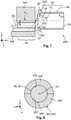
Figure 2 shows a flow diagram of a method for manufacturing thewiring system 10 shown inFigure 1 .Figure 3 shows a partial side view of aproduction machine 300 and of thewiring system 10 during a first to fifth method step 205-225.Figure 4 shows a sectional view, along a sectional plane A-A shown inFigure 3 , through theproduction machine 300 and thewiring system 10.Figure 5 shows a sectional view, along a sectional plane B-B shown inFigure 3 , through thewiring system 10 and theproduction machine 300 during thesixth method step 230.Figure 6 shows a longitudinal section through a part of theproduction machine 300 during theseventh method step 235 for producing thewiring system 10. - The first to fifth method steps 205 to 225 are explained in the following with reference to
Figure 3 . - In the
first method step 205, theelectric cable 20 and thecontact element 80 are provided. Thecontact element 80 may be connected, for example, to a transport strip (not shown). The transport strip may be arranged, for example, on a side adjacent to thetermination portion 85. The transport strip serves to automatically transport thecontact element 80 from a magazine of theproduction machine 300 to ananvil 305 of theproduction machine 300. Theelectric cable 20 may be provided, for example, ready cut to length in thefirst method step 205. - In a
second method step 210, theproduction machine 300 removes thecable insulation 25, starting from thefree end 140, from thefirst sub-portion 50 and, if applicable, also from the third and thefourth sub-portion second sub-portion 55, thecable insulation 25 remains on the electric conductor 30, and electrically insulates the electric conductor 30. Following removal of thecable insulation 25 from the first, third andfourth sub-portions second method step 210, the electric conductor 30 has an original cross-sectional area, across the sub-portions 50, 55, 56, 57, that corresponds to the second cross-sectional area. The first and the secondcentral axis - Additionally, in the
second method step 210, thetermination portion 85 may be cleaned to remove contamination from thetermination surface 95, for example, from the manufacture of thecontact element 80. - In a
third method step 215, thetermination portion 85 of thecontact element 80 is positioned on theanvil 305 of theproduction machine 300. Theanvil 305 is arranged, for example, in a fixed position. In this case, thetermination portion 85 lies flatly on a planar firstpressing surface 315 of theanvil 305, on a side that faces away from thetermination surface 95 and that is planar and parallel to thetermination surface 95. The firstpressing surface 315 is, for example, planar and extends in an xy-plane. - In a
fourth method step 220 that follows thethird method step 215, thefirst sub-portion 50 is positioned at thetermination surface 95. In the embodiment, the positioning is effected in such a manner that, in the transverse direction (y-direction), the firstcentral axis 65, which overlaps with the secondcentral axis 70 in thefourth method step 220, is positioned centrally in relation to a maximum extent b (cf.Figure 5 ) of thetermination portion 85. - In the fifth method step 225 (cf.
Figures 3 and 4 ), a holding means 320 of theproduction machine 300 is applied to thesecond sub-portion 55. The holding means 320 is arranged at a distance in the x-direction from theanvil 305 and thetermination portion 85. - The holding means 320 (cf.
Figure 4 ) has afirst holding shell 325 and at least onesecond holding shell 330. Thefirst holding shell 325 may be arranged, for example, on the top side of thesecond sub-portion 55, as inFigure 4 . Thefirst holding shell 325 is preferably annular, for example extending 180° around the secondcentral axis 70. Thesecond holding shell 330 is arranged, for example inFigure 4 , on the underside of thesecond sub-portion 55 and, like thefirst holding shell 325, has a partial annular shape, for example extending 180° around the secondcentral axis 70. The number of holding means 325, 330 is not fixed. Thus, the holding means 320 may also have a greater number of the holdingshells Figure 4 . What is essential is that the holdingshells circumferential side 335 against the first outercircumferential side 60 of thesecond sub-portion 55. Theelectric cable 20 in thesecond sub-portion 55 in this case is preferably encompassed over its full circumference by the holdingshells circumferential side 335 in this case may be realized so as to correspond to the first outercircumferential side 60. It is of particular advantage if the holdingshells contact surface 131 of thesecond sub-portion 55 of theelectric cable 20, against which the sealing element 130 bears in the assembled state. - In a
sixth method step 230 that follows thefifth method step 225, a welding means 341, preferably a sonotrode 345 (cf.Figures 3 and 5 ), is placed on thefirst sub-portion 50, on a side that faces away from thetermination portion 85. The welding means 341 may also be realized in a different manner. Thus, for example, an electric welding process would also be possible. - The welding means 341 has a second
pressing surface 350 on the side that faces towards thetermination portion 85, the secondpressing surface 350 being oriented parallel to the firstpressing surface 315 of theanvil 305 and thetermination surface 95. Preferably, the secondpressing surface 350 extends in an xy-plane. - Further, a first jaw 355 (cf.
Figure 5 ) and asecond jaw 360 that is arranged oppositely in the y-direction are preferably arranged at the side of thesonotrode 345 on thetermination portion 85. The first and thesecond jaw surface 365 laterally on a side that faces towards thefirst sub-portion 50, the holdingsurface 365 in each extending, for example, in a yz-plane. In this case the holdingsurface 365 of thefirst jaw 355 is arranged parallel to thesecond jaw 360 that is arranged opposite the holdingsurface 365. - Preferably, the
jaw termination surface 95 in the z-direction. There may also be a gap in the z-direction located between thejaw termination surface 95, but the gap in the z-direction is preferably narrower than a single diameter of the stranded wire 45 or of the stranded-wire braid 40. - In a
seventh method step 235 that follows the sixth method step 230 (cf.Figure 6 ), thefirst sub-portion 50 is welded to thetermination surface 95 by means of a welding process, in particular ultrasonic welding. The ultrasonic welding is effected by means of known ultrasonic welding methods. In this case, a mechanical vibration having a frequency in the ultrasonic range is introduced into thefirst sub-portion 50 via thesonotrode 345, on the side that faces away from thetermination surface 95. - In addition, the welding means 341 presses the
sonotrode 345 against thefirst sub-portion 50 with a pressing force FP. The pressing force FP acts vertically against the firstpressing surface 315 and is oriented in the z-direction. At the firstpressing surface 315 theanvil 305 provides a first counterforce FG1, which is directed contrary to the pressing force FP. Thetermination portion 85 is thereby prevented from being deflected in the z-direction. The pressing force FP is selected in such a manner that during the welding process, in particular the ultrasonic welding process, the secondpressing surface 350 compresses and compacts thefirst sub-portion 50. The compression by means of the pressing force FP in this case reduces cavities between the individual stranded wires 45, such that, despite the reduced first cross-sectional area, the electrical conductivity in thefirst sub-portion 50 and thesecond sub-portion 55 is identical. - The second cross-sectional area, which corresponds to the original cross-sectional area of the
first sub-portion 50 of the electric conductor 30, is in this case reduced to the first cross-sectional area of thefirst sub-portion 50. Further, thefirst sub-portion 50 is formed. During the welding process, in particular the ultrasonic welding process, the stranded wires 45 of the electric conductor 30 in thefirst sub-portion 50 are welded together. Due to the compressing, the firstcentral axis 65 is displaced from the overlapping arrangement with the secondcentral axis 70, towards thetermination surface 95. The predefined distance H can be set with precision by the pressing force FP and the first counterforce FG1. Further, a parallelism of the firstcentral axis 65 to thetermination surface 95 can be maintained with a small tolerance, over an extent of thefirst sub-portion 50 along the firstcentral axis 65, of ± 0.5 mm, in particular ± 0.2 mm, in particular ± 0.1 mm. - To limit lateral deflection of the
first sub-portion 50, during theseventh method step 235 thejaws first sub-portion 50, inside thelateral surface 370 in the transverse (y-direction). Thejaw surface 365 that prevents thefirst sub-portion 50 from adhering to thejaw - During the welding process, the position of the holding
shells Figure 6 ). Thefirst holding shell 325 provides a second counterforce FG2, and thesecond holding shell 330 provides a third counterforce FG3. The second counterforce FG2 and the third counterforce FG3 preferably each act in the z-direction. The third counterforce FG3 in this case is directed against the pressing force FP and prevents thesecond sub-portion 55 from being displaced in the z-direction. This ensures that, in the compressing of thefirst sub-portion 50, thefirst sub-portion 50 is arranged eccentrically in relation to the secondcentral axis 70 following compression, such that the firstcentral axis 65 has the predefined distance H between the firstcentral axis 65 and the secondcentral axis 70. - The second counterforce FG2, provided by the
first holding shell 325 arranged on top inFigure 6 , acts parallel to the pressing force FP and prevents thesecond sub-portion 55 from bending upwards in the z-direction during the compressing of thefirst sub-portion 50. The cylindrical shape of thesecond sub-portion 55 during the compressing process is thereby ensured. Further, the third and the fourth sub-portions 56, 57 are realized during the compressing and welding processes. Thethird sub-portion 56 in this case is formed into a truncated cone shape, with its thirdcentral axis 375 inclined at an angle to the first and secondcentral axes central axis - After an end position of the second
pressing surface 350 has been attained, and after thefirst sub-portion 50 has been finish-welded to thetermination portion 85, the secondpressing surface 350 is removed from thefirst sub-portion 50 in aneighth method step 240. Further, thejaws first sub-portion 50. Following removal of the secondpressing surface 350 and of thejaws shells shells shell jaw sonotrode 345. - In a
ninth method step 245 that follows theeighth method step 240, thewiring system 10 with the welded-oncontact element 80 is mounted in thecontact housing 75. - The method described above has the advantage that the distance H can be set in a defined manner independently of the layout of the stranded wires 45, such that, following mounting of the
wiring system 10 in thecontact housing 75, the sealing element 130 bears with full circumferential contact against thecable insulation 25, and thus a reliable sealing of thehousing interior 125 against theenvironment 135 is ensured. Further, a time-consuming set-up of theproduction machine 300 after a batch change of theelectric cable 20 can be dispensed with. As a result, thewiring system 10 can be manufactured particularly cost-effectively. - In a development of the method described in
Figure 3 , theanvil 305 can be moved in the z-direction with the secondpressing surface 350 during the compressing and welding of thefirst sub-portion 50, in order to set a particularly large distance H of thefirst sub-portion 50, with the firstcentral axis 65, in relation to thesecond sub-portion 55. In particular, it is thereby possible to dispense with offsetting theelectric cable 20, since the distance H in the z-direction is established during compressing and welding processes. Moreover, additional offsetting, bending or the like of theelectric cable 20 within thecontact housing 75 can be dispensed with. -
Figure 7 shows a longitudinal section through theproduction machine 300 executing a method for manufacturing thewiring system 10 according to a second embodiment. - The method is substantially identical to the method explained in
Figure 3 . In the following, only the differences between the method explained inFigure 7 and the method explained inFigure 3 will be discussed. The holdingshells third sub-portion 56. It is of particular advantage if the first and thesecond holding shell cable insulation 25 and encompass the electric conductor 30 with the innercircumferential side 335. -
Figure 8 shows a sectional view, along the sectional plane A-A shown inFigure 3 , during theseventh method step 235. - In this case, during the
seventh method step 235, the innercircumferential side 335 of the holdingshells third sub-portion 56 and provides the second and third counterforce FG2, FG3, which is introduced directly into the electric conductor 30. This design has the advantage that, compared toFigure 3 , bending of thethird sub-portion 56 during the compressing of thefirst sub-portion 50 is avoided. -
Figure 9 shows a schematic representation of awiring system 10 of a motor vehicle or of a charging station for charging a motor vehicle, according to a second embodiment. - The second embodiment of the
wiring system 10 shown inFigure 9 is substantially identical to thefirst wiring system 10 explained inFigure 1 . In the following, only the differences between thewiring system 10 shown inFigure 9 and thewiring system 10 shown inFigure 1 will be discussed. As a difference, for example, thesecond sub-portion 55 to thefourth sub-portion 57 are arranged bent at a predefined angle α in relation to thefirst sub-portion 50. The angle α is preferably obtuse. In particular, the angle α has a value of from 125° to 180°. - The first
central axis 65 and the secondcentral axis 70 are likewise arranged at an angle α. The firstcentral axis 65 and the secondcentral axis 70 are arranged in acommon plane 145, thecommon plane 145 being inclined, preferably perpendicularly, in relation to thetermination surface 95. - To manufacture the
wiring system 10 shown inFigure 9 , the method explained inFigure 2 may be used. Additionally, in thesixth method step 230, the electric conductor is bent in the third and thefourth sub-portion second sub-portion 55 is arranged at an angle α in relation to thefirst sub-portion 50. The bending may be effected, for example, by moving the holding means 320 relative to theanvil 305 and thesonotrode 345. To achieve the predefined angle α, thesecond sub-portion 55 may also be bent over relative to thefirst sub-portion 50 during bending of theelectric cable 20. The holding means 320 keeps thesecond sub-portion 55 inclined while thefirst sub-portion 50 is being welded. The method has the advantage that, following execution of the method, thesecond sub-portion 55 is precisely aligned at the predefined angle α. -
- 10
- wiring system
- 15
- contact means
- 20
- electric cable
- 25
- cable insulation
- 30
- electric conductor
- 35
- stranded-wire bundle, electric conductor
- 40
- stranded-wire braid
- 45
- stranded wire
- 50
- first sub-portion
- 55
- second sub-portion
- 56
- third sub-portion
- 57
- fourth sub-portion
- 60
- first outer circumferential side
- 65
- first central axis
- 70
- second central axis
- 75
- contact housing
- 80
- contact element
- 85
- termination portion
- 90
- contact pin
- 95
- termination surface
- 100
- connection portion
- 105
- fixed end
- 110
- contact receiver
- 115
- plug-in axis
- 120
- leadthrough
- 125
- housing interior
- 130
- sealing element
- 135
- environment
- 140
- free end
- 205
- first method step
- 210
- second method step
- 215
- third method step
- 220
- fourth method step
- 225
- fifth method step
- 230
- sixth method step
- 235
- seventh method step
- 240
- eighth method step
- 245
- ninth method step
- 300
- production machine
- 305
- anvil
- 310
- further contact surface
- 315
- first pressing surface (of the anvil)
- 320
- holding means
- 325
- first holding shell
- 330
- second holding shell
- 335
- inner circumferential side
- 340
- second outer circumferential side
- 341
- welding means
- 345
- sonotrode
- 350
- second pressing surface
- 355
- first jaw
- 360
- second jaw
- 365
- holding surface
- 370
- lateral surface
- 375
- third central axis
- H
- distance
- FP
- pressing force
- FG1
- first counterforce
- FG2
- second counterforce
- FG3
- third counterforce
Claims (11)
- Method for manufacturing a wiring system (10) for transmitting electrical power in an electric vehicle or a charging station of an electric vehicle,- there being provided an electric cable (20) that has at least one electric conductor (30), and a contact element (80) that has a termination portion (85),- a cable insulation (25) being removed in a first sub-portion (50) of the electric cable (20), and the cable insulation (25) remaining on the electric conductor (30) in a second sub-portion (55) of the electric cable (20) arranged so as to be offset from the first sub-portion (50),- the electric conductor (30) being welded, by the first sub-portion (50), to a termination surface (95) of the termination portion (85),- during welding, the first sub-portion (50) being pressed against the termination portion (85),
characterized in that- a holding means (320) encompasses the second sub-portion (55) at least partially, preferably over its full circumference,- the holding means (320) supporting the second sub-portion (55) at least during the compressing and welding of the first sub-portion (50) and maintaining a position of the second sub-portion (55). - Method according to Claim 1,- in the first sub-portion (50) of the electric cable (20) the electric conductor (30) extending along a first central axis (65), and in the second sub-portion (55) of the electric cable (20) the electric conductor (30) extending along a second central axis (70), and the first and the second central axis (65, 70) overlapping prior to compression,- the first sub-portion (50) being pressed in such a manner that the first central axis (65) is oriented parallel to the termination surface (95).
- Method according to Claim 1,- in the first sub-portion (50) of the electric cable (20) the electric conductor (30) extending along a first central axis (65), and in the second sub-portion (55) of the electric cable (20) the electric conductor (30) extending along a second central axis (70), and the first and the second central axis (65, 70) overlapping prior to compression,- the first sub-portion (50) being bent relative to the second sub-portion (55) in such a manner that the first sub-portion (50) and the second sub-portion (55) are arranged at a predefined angle (α) in relation to each other.
- Method according to any one of the preceding claims,- the holding means (320) encompassing the second sub-portion (55), in a region of a contact surface (131) for a sealing element (130), in such a manner that an outer contour of the second sub-portion (55) is maintained throughout the compressing and welding.
- Method according to any one of the preceding claims,- a sonotrode (345) being applied to the first sub-portion (50) on a side that faces away from the termination surface (95),- the sonotrode (345) introducing a pressing force (FP), acting in the direction of the termination surface (95), into the first sub-portion (50),- the first sub-portion (50) being supported laterally inclined in relation to the termination surface (95).
- Method according to any one of the preceding claims,- the electric conductor (30) having an original cross-sectional area across the first and the second sub-portion (50, 55) prior to welding,- the original cross-sectional area being 6 mm2 to 150 mm2,- the electric conductor (30) being compacted in the first sub-portion (50), and a first cross-sectional area of the first sub-portion (50) being smaller than the original cross-sectional area.
- Wiring system (10) for high current transmission in a motor vehicle or a charging station, which is manufactured according to any one of the preceding claims,- having an electric cable (20) and a contact means (15) that has at least one contact element (80),- the electric cable (20) having a stranded electric conductor (30) and a cable insulation (25),- the contact element (80) having a plate-type termination portion (85),- in a first sub-portion (50) of the electric cable (20), the electric conductor (30) being welded, in particular ultrasonically welded, to the termination portion (85), and the cable insulation (25) at least partially sheathing the electric conductor (30) in a second sub-portion (55) of the electric cable (20) that is arranged so as to be offset from the first sub-portion (50),- in the first sub-portion (50) the electric conductor (30) extending along a first central axis (65), and in the second sub-portion (55) the electric conductor (30) extending along a second central axis (70),- the first central axis (65) being arranged so as to be offset at a predefined distance (H) and/or at a predefined angle (α) from the second central axis (70), towards the termination portion (85).
- Wiring system (10) according to Claim 7,- the electric conductor (30) having a first cross-sectional area in the first sub-portion (50).- the electric conductor (30) having a second cross-sectional area in the second sub-portion (55),- the first cross-sectional area being smaller than the second cross-sectional area.
- Wiring system (10) according to either one of Claims 7 or 8,- the first sub-portion (50) being arranged eccentrically in relation to the second central axis (70) of the second sub-portion (55).
- Wiring system (10) according to any one of Claims 7 to 9,- the first central axis (65) being aligned parallel to the termination portion (85),- a parallelism between the termination portion (85) and the first central axis (65) having, over an extent of the first sub-portion (50), a tolerance of ± 0.5 mm, in particular ± 0.2 mm, in particular ± 0.1 mm.
- Wiring system (10) according to any one of Claims 7 to 10,- the first central axis (65) and the second central axis (70) being arranged in a common plane,- the common plane being inclined, preferably oriented perpendicularly, in relation to the termination surface (95).
Applications Claiming Priority (1)
| Application Number | Priority Date | Filing Date | Title |
|---|---|---|---|
| DE102020124705.2A DE102020124705A1 (en) | 2020-09-22 | 2020-09-22 | Method for manufacturing a piping system and piping system |
Publications (2)
| Publication Number | Publication Date |
|---|---|
| EP3972062A1 true EP3972062A1 (en) | 2022-03-23 |
| EP3972062B1 EP3972062B1 (en) | 2026-04-15 |
Family
ID=77821643
Family Applications (1)
| Application Number | Title | Priority Date | Filing Date |
|---|---|---|---|
| EP21197410.0A Active EP3972062B1 (en) | 2020-09-22 | 2021-09-17 | Method for manufacturing a wiring system, and wiring system |
Country Status (6)
| Country | Link |
|---|---|
| US (1) | US11777299B2 (en) |
| EP (1) | EP3972062B1 (en) |
| JP (1) | JP7270694B2 (en) |
| KR (1) | KR102677906B1 (en) |
| CN (1) | CN114256710B (en) |
| DE (1) | DE102020124705A1 (en) |
Families Citing this family (3)
| Publication number | Priority date | Publication date | Assignee | Title |
|---|---|---|---|---|
| JP2023170669A (en) * | 2022-05-19 | 2023-12-01 | 矢崎総業株式会社 | wire holder |
| JP2024113771A (en) * | 2023-02-10 | 2024-08-23 | 住友電装株式会社 | Charging connectors and charging connector product family |
| US20240307994A1 (en) * | 2023-03-15 | 2024-09-19 | Illinois Tool Works Inc. | Ultrasonically welded fittings and welding cables |
Citations (5)
| Publication number | Priority date | Publication date | Assignee | Title |
|---|---|---|---|---|
| US6854637B2 (en) | 2003-02-20 | 2005-02-15 | Freescale Semiconductor, Inc. | Wirebonding insulated wire |
| DE102013021278B3 (en) * | 2013-12-17 | 2015-06-03 | Nexans | Method for electrically conducting a connection to a contact element |
| US10511105B2 (en) * | 2018-03-01 | 2019-12-17 | Yazaki Corporation | Electric wire with terminal and method of manufacturing electric wire with terminal |
| US10601147B2 (en) * | 2016-10-31 | 2020-03-24 | Sumitomo Wiring Systems, Ltd. | Method of bonding core wire and bonding object, ultrasonic bonding device, and junction between core wire and bonding object |
| US10756498B1 (en) * | 2019-03-22 | 2020-08-25 | Te Connectivity Corporation | Terminal heat exchanger for an electrical connector |
Family Cites Families (12)
| Publication number | Priority date | Publication date | Assignee | Title |
|---|---|---|---|---|
| DE3851901T2 (en) * | 1987-01-26 | 1995-04-13 | Hitachi Ltd | Welding a wire. |
| JP2009202158A (en) * | 2006-06-09 | 2009-09-10 | Phoeton Corp | Laser welding method |
| DE102010053919A1 (en) | 2010-12-09 | 2012-06-14 | Bayerische Motoren Werke Aktiengesellschaft | Method for contacting insulated cable with metallic contact part i.e. cable shoe, of automobile, involves mechanically pressing stripped end of cable on mounting surface, and producing solder connection between conductor and contact part |
| JP2013004406A (en) * | 2011-06-20 | 2013-01-07 | Hitachi Cable Ltd | Manufacturing method of wire with terminal |
| DE102013219150A1 (en) * | 2013-09-24 | 2015-04-09 | Elringklinger Ag | Method for producing an electrically conductive connection between an electrical line and an electrically conductive component |
| JP2015153604A (en) * | 2014-02-14 | 2015-08-24 | 住友電装株式会社 | Terminal and electrical connection structure for the same |
| JP6719873B2 (en) * | 2015-07-28 | 2020-07-08 | 日立金属株式会社 | Wiring assembly for vehicle equipment |
| AT519175B1 (en) * | 2016-08-03 | 2019-01-15 | Gebauer & Griller Kabelwerke Ges M B H | ULTRASONIC WELDING OF A LADDER WITH A CONTACT PART |
| JP2018147823A (en) * | 2017-03-08 | 2018-09-20 | 株式会社フジクラ | Terminal |
| CN209217310U (en) * | 2018-12-15 | 2019-08-06 | 深圳市集全新能源科技有限公司 | A kind of charging connection equipment and charging system |
| DE102018132823A1 (en) * | 2018-12-19 | 2020-06-25 | Rosenberger Hochfrequenztechnik Gmbh & Co. Kg | Cable connector assembly, cable connector and crimp |
| CN110048282A (en) * | 2019-05-31 | 2019-07-23 | 南京康尼机电股份有限公司 | A kind of socket for electric car and the electric car using it |
-
2020
- 2020-09-22 DE DE102020124705.2A patent/DE102020124705A1/en active Pending
-
2021
- 2021-09-15 KR KR1020210123293A patent/KR102677906B1/en active Active
- 2021-09-16 JP JP2021150732A patent/JP7270694B2/en active Active
- 2021-09-17 EP EP21197410.0A patent/EP3972062B1/en active Active
- 2021-09-17 CN CN202111091302.0A patent/CN114256710B/en active Active
- 2021-09-22 US US17/481,646 patent/US11777299B2/en active Active
Patent Citations (5)
| Publication number | Priority date | Publication date | Assignee | Title |
|---|---|---|---|---|
| US6854637B2 (en) | 2003-02-20 | 2005-02-15 | Freescale Semiconductor, Inc. | Wirebonding insulated wire |
| DE102013021278B3 (en) * | 2013-12-17 | 2015-06-03 | Nexans | Method for electrically conducting a connection to a contact element |
| US10601147B2 (en) * | 2016-10-31 | 2020-03-24 | Sumitomo Wiring Systems, Ltd. | Method of bonding core wire and bonding object, ultrasonic bonding device, and junction between core wire and bonding object |
| US10511105B2 (en) * | 2018-03-01 | 2019-12-17 | Yazaki Corporation | Electric wire with terminal and method of manufacturing electric wire with terminal |
| US10756498B1 (en) * | 2019-03-22 | 2020-08-25 | Te Connectivity Corporation | Terminal heat exchanger for an electrical connector |
Also Published As
| Publication number | Publication date |
|---|---|
| US11777299B2 (en) | 2023-10-03 |
| KR102677906B1 (en) | 2024-06-21 |
| JP7270694B2 (en) | 2023-05-10 |
| DE102020124705A1 (en) | 2022-03-24 |
| US20220094151A1 (en) | 2022-03-24 |
| KR20220039602A (en) | 2022-03-29 |
| JP2022051698A (en) | 2022-04-01 |
| EP3972062B1 (en) | 2026-04-15 |
| CN114256710A (en) | 2022-03-29 |
| CN114256710B (en) | 2025-01-24 |
Similar Documents
| Publication | Publication Date | Title |
|---|---|---|
| EP3972062B1 (en) | Method for manufacturing a wiring system, and wiring system | |
| US8574008B2 (en) | Battery cell connector | |
| CN110832713B (en) | Method for manufacturing an electrical circuit arrangement | |
| US9853280B2 (en) | Terminal assembly with a multi-wire planar cable | |
| US10978815B2 (en) | Joining a terminal element with a stranded conductor | |
| CN106463846A (en) | Crimped welded joint | |
| US11394163B2 (en) | Electric line assembly with direct contacting and method for producing same | |
| WO2014129092A1 (en) | Connection structure, terminal crimping member, wire harness, connector, method for crimping connection structure, and crimping device for crimping same | |
| CN113939957B (en) | Electrical connection socket for motor vehicle electrical network conductors | |
| JP2011014438A (en) | Electric wire connection structure, and conductive line for vehicle having the same | |
| US10714842B2 (en) | Electrical connection assembly and method for manufacturing same | |
| US8272901B2 (en) | Crimp contacts and electrical connector assemblies including the same | |
| JP2011090804A (en) | Electric wire with terminal fitting and method of manufacturing the same | |
| JP5223798B2 (en) | Electric wire connection structure and vehicle conductive path having the electric wire connection structure | |
| JP6536933B2 (en) | Manufacturing method of wire with terminal | |
| US11616334B2 (en) | Method of manufacturing cable assembly, horn chip used in the method and cable assembly manufactured by the method | |
| EP3863120B1 (en) | Electric wire connection structure and connection method | |
| CN117060192A (en) | Wire harness terminal crimping machine for feeding multiple types of terminals | |
| CN118380784A (en) | Terminal fittings and electric wires with terminals | |
| JP5445805B2 (en) | Electric wire connection structure and vehicle conductive path having the electric wire connection structure | |
| US9899893B2 (en) | Electric motor including terminal formed by electric swaging and electric swaging method | |
| JP2017098110A (en) | Terminal-equipped wire and method of manufacturing the same | |
| US20240186725A1 (en) | Terminal-equipped wire and method for manufacturing terminal-equipped wire | |
| EP4068518B1 (en) | Braided part connection structure | |
| US7856703B2 (en) | Method for making a short-circuiting member and method for making a commutator |
Legal Events
| Date | Code | Title | Description |
|---|---|---|---|
| PUAI | Public reference made under article 153(3) epc to a published international application that has entered the european phase |
Free format text: ORIGINAL CODE: 0009012 |
|
| STAA | Information on the status of an ep patent application or granted ep patent |
Free format text: STATUS: THE APPLICATION HAS BEEN PUBLISHED |
|
| AK | Designated contracting states |
Kind code of ref document: A1 Designated state(s): AL AT BE BG CH CY CZ DE DK EE ES FI FR GB GR HR HU IE IS IT LI LT LU LV MC MK MT NL NO PL PT RO RS SE SI SK SM TR |
|
| STAA | Information on the status of an ep patent application or granted ep patent |
Free format text: STATUS: REQUEST FOR EXAMINATION WAS MADE |
|
| 17P | Request for examination filed |
Effective date: 20220329 |
|
| RBV | Designated contracting states (corrected) |
Designated state(s): AL AT BE BG CH CY CZ DE DK EE ES FI FR GB GR HR HU IE IS IT LI LT LU LV MC MK MT NL NO PL PT RO RS SE SI SK SM TR |
|
| STAA | Information on the status of an ep patent application or granted ep patent |
Free format text: STATUS: EXAMINATION IS IN PROGRESS |
|
| 17Q | First examination report despatched |
Effective date: 20240315 |
|
| GRAP | Despatch of communication of intention to grant a patent |
Free format text: ORIGINAL CODE: EPIDOSNIGR1 |
|
| STAA | Information on the status of an ep patent application or granted ep patent |
Free format text: STATUS: GRANT OF PATENT IS INTENDED |
|
| INTG | Intention to grant announced |
Effective date: 20251223 |
|
| GRAS | Grant fee paid |
Free format text: ORIGINAL CODE: EPIDOSNIGR3 |
|
| GRAA | (expected) grant |
Free format text: ORIGINAL CODE: 0009210 |
|
| STAA | Information on the status of an ep patent application or granted ep patent |
Free format text: STATUS: THE PATENT HAS BEEN GRANTED |
|
| AK | Designated contracting states |
Kind code of ref document: B1 Designated state(s): AL AT BE BG CH CY CZ DE DK EE ES FI FR GB GR HR HU IE IS IT LI LT LU LV MC MK MT NL NO PL PT RO RS SE SI SK SM TR |
|
| REG | Reference to a national code |
Ref country code: CH Ref legal event code: F10 Free format text: ST27 STATUS EVENT CODE: U-0-0-F10-F00 (AS PROVIDED BY THE NATIONAL OFFICE) Effective date: 20260415 |
|
| REG | Reference to a national code |
Ref country code: DE Ref legal event code: R096 Ref document number: 602021052020 Country of ref document: DE |