EP3972060A1 - Connector - Google Patents
Connector Download PDFInfo
- Publication number
- EP3972060A1 EP3972060A1 EP21186848.4A EP21186848A EP3972060A1 EP 3972060 A1 EP3972060 A1 EP 3972060A1 EP 21186848 A EP21186848 A EP 21186848A EP 3972060 A1 EP3972060 A1 EP 3972060A1
- Authority
- EP
- European Patent Office
- Prior art keywords
- contact
- protrusions
- connector
- sleeve member
- rear direction
- Prior art date
- Legal status (The legal status is an assumption and is not a legal conclusion. Google has not performed a legal analysis and makes no representation as to the accuracy of the status listed.)
- Granted
Links
- 230000004308 accommodation Effects 0.000 claims abstract description 30
- 239000002184 metal Substances 0.000 description 13
- 238000012856 packing Methods 0.000 description 6
- 238000004519 manufacturing process Methods 0.000 description 4
- 238000012986 modification Methods 0.000 description 4
- 230000004048 modification Effects 0.000 description 4
- 230000008878 coupling Effects 0.000 description 2
- 238000010168 coupling process Methods 0.000 description 2
- 238000005859 coupling reaction Methods 0.000 description 2
- 230000013011 mating Effects 0.000 description 2
- 229920003051 synthetic elastomer Polymers 0.000 description 2
- 239000005061 synthetic rubber Substances 0.000 description 2
- XLYOFNOQVPJJNP-UHFFFAOYSA-N water Substances O XLYOFNOQVPJJNP-UHFFFAOYSA-N 0.000 description 2
- 238000005452 bending Methods 0.000 description 1
- 238000003780 insertion Methods 0.000 description 1
- 230000037431 insertion Effects 0.000 description 1
- 238000000465 moulding Methods 0.000 description 1
- 230000001105 regulatory effect Effects 0.000 description 1
Images


Classifications
-
- H—ELECTRICITY
- H01—ELECTRIC ELEMENTS
- H01R—ELECTRICALLY-CONDUCTIVE CONNECTIONS; STRUCTURAL ASSOCIATIONS OF A PLURALITY OF MUTUALLY-INSULATED ELECTRICAL CONNECTING ELEMENTS; COUPLING DEVICES; CURRENT COLLECTORS
- H01R13/00—Details of coupling devices of the kinds covered by groups H01R12/70 or H01R24/00 - H01R33/00
- H01R13/46—Bases; Cases
- H01R13/52—Dustproof, splashproof, drip-proof, waterproof, or flameproof cases
- H01R13/521—Sealing between contact members and housing, e.g. sealing insert
-
- H—ELECTRICITY
- H01—ELECTRIC ELEMENTS
- H01R—ELECTRICALLY-CONDUCTIVE CONNECTIONS; STRUCTURAL ASSOCIATIONS OF A PLURALITY OF MUTUALLY-INSULATED ELECTRICAL CONNECTING ELEMENTS; COUPLING DEVICES; CURRENT COLLECTORS
- H01R13/00—Details of coupling devices of the kinds covered by groups H01R12/70 or H01R24/00 - H01R33/00
- H01R13/58—Means for relieving strain on wire connection, e.g. cord grip, for avoiding loosening of connections between wires and terminals within a coupling device terminating a cable
- H01R13/5841—Means for relieving strain on wire connection, e.g. cord grip, for avoiding loosening of connections between wires and terminals within a coupling device terminating a cable allowing different orientations of the cable with respect to the coupling direction
-
- B—PERFORMING OPERATIONS; TRANSPORTING
- B60—VEHICLES IN GENERAL
- B60L—PROPULSION OF ELECTRICALLY-PROPELLED VEHICLES; SUPPLYING ELECTRIC POWER FOR AUXILIARY EQUIPMENT OF ELECTRICALLY-PROPELLED VEHICLES; ELECTRODYNAMIC BRAKE SYSTEMS FOR VEHICLES IN GENERAL; MAGNETIC SUSPENSION OR LEVITATION FOR VEHICLES; MONITORING OPERATING VARIABLES OF ELECTRICALLY-PROPELLED VEHICLES; ELECTRIC SAFETY DEVICES FOR ELECTRICALLY-PROPELLED VEHICLES
- B60L53/00—Methods of charging batteries, specially adapted for electric vehicles; Charging stations or on-board charging equipment therefor; Exchange of energy storage elements in electric vehicles
- B60L53/10—Methods of charging batteries, specially adapted for electric vehicles; Charging stations or on-board charging equipment therefor; Exchange of energy storage elements in electric vehicles characterised by the energy transfer between the charging station and the vehicle
- B60L53/14—Conductive energy transfer
- B60L53/16—Connectors, e.g. plugs or sockets, specially adapted for charging electric vehicles
-
- H—ELECTRICITY
- H01—ELECTRIC ELEMENTS
- H01R—ELECTRICALLY-CONDUCTIVE CONNECTIONS; STRUCTURAL ASSOCIATIONS OF A PLURALITY OF MUTUALLY-INSULATED ELECTRICAL CONNECTING ELEMENTS; COUPLING DEVICES; CURRENT COLLECTORS
- H01R13/00—Details of coupling devices of the kinds covered by groups H01R12/70 or H01R24/00 - H01R33/00
- H01R13/40—Securing contact members in or to a base or case; Insulating of contact members
- H01R13/42—Securing in a demountable manner
- H01R13/436—Securing a plurality of contact members by one locking piece or operation
- H01R13/4367—Insertion of locking piece from the rear
-
- H—ELECTRICITY
- H01—ELECTRIC ELEMENTS
- H01R—ELECTRICALLY-CONDUCTIVE CONNECTIONS; STRUCTURAL ASSOCIATIONS OF A PLURALITY OF MUTUALLY-INSULATED ELECTRICAL CONNECTING ELEMENTS; COUPLING DEVICES; CURRENT COLLECTORS
- H01R13/00—Details of coupling devices of the kinds covered by groups H01R12/70 or H01R24/00 - H01R33/00
- H01R13/46—Bases; Cases
- H01R13/502—Bases; Cases composed of different pieces
- H01R13/506—Bases; Cases composed of different pieces assembled by snap action of the parts
-
- H—ELECTRICITY
- H01—ELECTRIC ELEMENTS
- H01R—ELECTRICALLY-CONDUCTIVE CONNECTIONS; STRUCTURAL ASSOCIATIONS OF A PLURALITY OF MUTUALLY-INSULATED ELECTRICAL CONNECTING ELEMENTS; COUPLING DEVICES; CURRENT COLLECTORS
- H01R13/00—Details of coupling devices of the kinds covered by groups H01R12/70 or H01R24/00 - H01R33/00
- H01R13/46—Bases; Cases
- H01R13/52—Dustproof, splashproof, drip-proof, waterproof, or flameproof cases
- H01R13/5205—Sealing means between cable and housing, e.g. grommet
-
- H—ELECTRICITY
- H01—ELECTRIC ELEMENTS
- H01R—ELECTRICALLY-CONDUCTIVE CONNECTIONS; STRUCTURAL ASSOCIATIONS OF A PLURALITY OF MUTUALLY-INSULATED ELECTRICAL CONNECTING ELEMENTS; COUPLING DEVICES; CURRENT COLLECTORS
- H01R2201/00—Connectors or connections adapted for particular applications
- H01R2201/26—Connectors or connections adapted for particular applications for vehicles
-
- Y—GENERAL TAGGING OF NEW TECHNOLOGICAL DEVELOPMENTS; GENERAL TAGGING OF CROSS-SECTIONAL TECHNOLOGIES SPANNING OVER SEVERAL SECTIONS OF THE IPC; TECHNICAL SUBJECTS COVERED BY FORMER USPC CROSS-REFERENCE ART COLLECTIONS [XRACs] AND DIGESTS
- Y02—TECHNOLOGIES OR APPLICATIONS FOR MITIGATION OR ADAPTATION AGAINST CLIMATE CHANGE
- Y02T—CLIMATE CHANGE MITIGATION TECHNOLOGIES RELATED TO TRANSPORTATION
- Y02T10/00—Road transport of goods or passengers
- Y02T10/60—Other road transportation technologies with climate change mitigation effect
- Y02T10/70—Energy storage systems for electromobility, e.g. batteries
-
- Y—GENERAL TAGGING OF NEW TECHNOLOGICAL DEVELOPMENTS; GENERAL TAGGING OF CROSS-SECTIONAL TECHNOLOGIES SPANNING OVER SEVERAL SECTIONS OF THE IPC; TECHNICAL SUBJECTS COVERED BY FORMER USPC CROSS-REFERENCE ART COLLECTIONS [XRACs] AND DIGESTS
- Y02—TECHNOLOGIES OR APPLICATIONS FOR MITIGATION OR ADAPTATION AGAINST CLIMATE CHANGE
- Y02T—CLIMATE CHANGE MITIGATION TECHNOLOGIES RELATED TO TRANSPORTATION
- Y02T10/00—Road transport of goods or passengers
- Y02T10/60—Other road transportation technologies with climate change mitigation effect
- Y02T10/7072—Electromobility specific charging systems or methods for batteries, ultracapacitors, supercapacitors or double-layer capacitors
-
- Y—GENERAL TAGGING OF NEW TECHNOLOGICAL DEVELOPMENTS; GENERAL TAGGING OF CROSS-SECTIONAL TECHNOLOGIES SPANNING OVER SEVERAL SECTIONS OF THE IPC; TECHNICAL SUBJECTS COVERED BY FORMER USPC CROSS-REFERENCE ART COLLECTIONS [XRACs] AND DIGESTS
- Y02—TECHNOLOGIES OR APPLICATIONS FOR MITIGATION OR ADAPTATION AGAINST CLIMATE CHANGE
- Y02T—CLIMATE CHANGE MITIGATION TECHNOLOGIES RELATED TO TRANSPORTATION
- Y02T90/00—Enabling technologies or technologies with a potential or indirect contribution to GHG emissions mitigation
- Y02T90/10—Technologies relating to charging of electric vehicles
- Y02T90/14—Plug-in electric vehicles
Definitions
- This invention relates to a connector, particularly to a connector provided with a contact which is connected to an electrical wire and accommodated in a housing.
- a connector provided with a contact which is connected to an electrical wire and accommodated in a housing is disclosed in JP2010-55809A (Patent Document 1) for example.
- a connector 90 of Patent Document 1 is provided with a terminal metal 910, a connector housing 920, a rear holder 930, a sleeve member 940, a center packing 950 and a rear packing 960.
- the connector housing 920 is provided with a terminal accommodation room 922.
- the terminal metal 910 is accommodated in the terminal accommodation room 922 and connected to an electrical wire 970.
- the rear holder 930 is attached to a rear portion of the connector housing 920 and fills the terminal accommodation room 922 in part.
- the terminal metal 910 has a flange portion 912.
- the flange portion 912 prevents the terminal metal 910 from being moved forward with respect to the connector housing 920.
- the center packing 950 is attached to the flange portion 912.
- the sleeve member 940 is arranged between the flange portion 912 of the terminal metal 910 and the rear holder 930. Furthermore, between the sleeve member 940 and the rear holder 930, the rear packing 960 is arranged. A part of the terminal metal 910 and a part of the electrical wire 970 are located inside the sleeve member 940. The electrical wire 970 passes through a through hole 962 formed in the rear packing and a through hole 932 formed in the rear holder 930 and extends rearward. The sleeve member 940 regulates rearward movement of the terminal metal 910 with respect to the connector housing 920 together with the rear packing 960.
- the connector 90 of Patent Document 1 is structured so that a front-end surface of the sleeve member 940 is brought into abutment with the flange portion 912 of the terminal metal 910. If the front-end surface of the sleeve member 940 is perpendicular to a longitudinal direction of the sleeve member 940, the terminal metal 910 would extend straight along the longitudinal direction of the sleeve member 940 when the front-end surface of the sleeve member 940 is brought into abutment with the terminal metal 910.
- the terminal metal 910 would be inclined with respect to the longitudinal direction of the sleeve member 940 if the front-end surface of the sleeve member 940 is brought into abutment with the terminal metal 910.
- the connector 90 of Patent Document 1 has a problem that the terminal metal 910 may be inclined with respect to the sleeve member 940.
- a connector comprising a housing, a holder, a contact, an electrical wire and a sleeve member.
- the housing is formed with a contact accommodation portion.
- the contact is accommodated in the contact accommodation portion at least in part.
- the holder is attached to the housing and defines a rear end of the contact accommodation portion in a front-rear direction.
- the holder is formed with a through hole piercing thereof in the front-rear direction.
- the electrical wire is connected to the contact and extends from the contact accommodation portion to an outside of the contact accommodation portion through the through hole of the holder.
- the contact is provided with an abutment portion.
- the sleeve member has a main portion and three or more front protrusions.
- the main portion extends in the front-rear direction and has a C-shape section on a plane perpendicular to the front-rear direction.
- Each of the front protrusions protrudes forward from a front end of the main portion in the front-rear direction.
- the sleeve member is attached to the contact so as to accommodate a part of the contact and a part of the electrical wire in the main portion and located between the abutment portion and the holder in the front-rear direction. At least three of the front protrusions are brought into abutment with the abutment portion.
- the sleeve member has the three or more front protrusions, and the at least three of the front protrusions are brought into contact with the abutment portion of the contact. If the contact is tilted with respect to the sleeve member, it is only need to adjust a protruding dimension of one or more of the front protrusions. This is easy in comparison with adjusting a tilt of the whole of the front-end surface of the sleeve member that has the C-shape.
- adjusting protruding amount of the front protrusion in a mold is remarkably easier than adjusting the tilt of the whole of the front-end surface having the C-shape in a mold.
- a connector 10 is a charging connector for an electric vehicle, wherein it is attached to an end of a cable 80.
- the present invention is not limited thereto. The present invention is applicable to connectors for every use.
- the connector 10 is provided with a mating portion 12 and a body 14.
- the body 14 has a base shell 141 and a cover shell 143.
- the base shell 141 is provided with housings 20.
- the number of the housings 20 is two.
- the connector of the present invention should be provided with at least one housing 20.
- the housings 20 may not be provided to the base shell 141 but be exposed outside.
- holders 30 are attached to the housings 20, respectively.
- each of the holders 30 is attached to a rear-end portion of the housing 20 corresponding thereto.
- a front-rear direction is a Y-direction.
- a negative Y-direction is directed forward while a positive Y-direction is directed rearward.
- the holder 30 has an end face portion 32 and a sidewall portion 34 extending forward from the end face portion 32.
- the end face portion 32 is formed with a through hole 321 piercing the end face portion 32 in the front-rear direction.
- the housing 20 is formed with a contact accommodation portion 22.
- the holder 30 attached to the housing 20 defines a rear end of the contact accommodation portion 22 in the front-rear direction.
- a contact assembly 16 is accommodated in the contact accommodation portion 22 of the housing 20, a contact assembly 16 is accommodated in the contact accommodation portion 22 of the housing 20, a contact assembly 16 is accommodated.
- a contact 40, a sleeve member 50, an annular member 60, a first waterproof member 70 and a sensor 72 are accommodated in the contact accommodation portion 22.
- the connector 10 is provided with the contact 40, the sleeve member 50, the annular member 60, the first waterproof member 70 and the sensor 72.
- the annular member 60, the first waterproof member 70 and the sensor 72 are not always necessary.
- the connector of the present invention should be provided with at least the contact 40 and the sleeve member 50 in addition to the housing 20 and the holder 30.
- the contact 40 has a multistage cylindrical shape.
- the contact 40 has a connecting portion 42, a barrel portion 44 and a wire connection portion 46.
- the connecting portion 42, the barrel portion 44 and the wire connection portion 46 are arranged in this order in the front-rear direction so that their central axes are coincide with one another.
- the connecting portion 42 has a base portion 421 with a cylindrical shape and a plurality of contact pieces 423 extending forward from the base portion 421.
- the contact pieces 423 are arranged at regular intervals in a circumference direction in a plane perpendicular to the front-rear direction.
- the contact pieces 423 are resiliently deformable.
- the contact pieces 423 come into contact with a mating contact (not shown) when the connector 10 is mated with an inlet (not shown).
- the number of the contact pieces 423 is eight.
- the connecting portion 42 may be freely designed about its structure and shape.
- the barrel portion 44 has an external diameter larger than that of the base portion 421 of the connecting portion 42.
- the barrel portion 44 has a flange portion 441.
- An external diameter of the flange portion 441 is larger than that of the other portion of the barrel portion 44.
- the flange portion 441 has a front-end face 443 and a rear-end face 445. As described later, the rear-end face 445 of the flange portion 441 works as an abutment portion. In other words, the contact 40 is provided with the abutment portion.
- an outer circumference surface of the flange portion 441 of the contact 40 is formed with a groove 447 recessed inward.
- the first waterproof member 70 is attached to the groove 447.
- the present invention is not limited thereto. If the first waterproof member 70 is unnecessary, the groove 447 is unnecessary either.
- the barrel portion 44 is further formed with a hole 449 with a bottom.
- the hole 449 is bored along an up-down direction perpendicular to the front-rear direction.
- the up-down direction is a Z-direction.
- a positive Z-direction is directed upward while a negative Z-direction is directed downward.
- the sensor 72 is inserted and arranged in a lengthwise direction. Wirings 721 of the sensor 72 extend upward from the sensor 72 and are bent at an approximately right angle at an edge of the hole 449. In other words, the wirings 721 of the sensor 72 are bent in the front-rear direction at the edge of the hole 449.
- the wirings 721 of the sensor 72 extend outside the contact accommodation portion 22 through the through hole 321 of the holders 30.
- insertion and arrangement of the sensor 72 in the hole 449 formed in the up-down direction perpendicular to the front-rear direction and bending the wirings 721 at the approximately right angle allow a length of the barrel portion 44 to be reduced in the front-rear direction.
- bent portions of the wirings 721 are slightly rose from the barrel portion 44, they do not matter because they are located in a slit 521 of the sleeve member 50.
- the sensor 72 is a temperature sensor. However, the present invention is not limited thereto. If the sensor 72 is unnecessary, the hole 449 is unnecessary either.
- the wire connection portion 46 has an external diameter smaller than that of the barrel portion 44.
- the external diameter of the wire connection portion 46 may be equal to the external diameter of the barrel portion 44.
- an electrical wire 82 included in the cable 80 is connected to the wire connection portion 46.
- the electrical wire 82 connected to the wire connection portion 46 of the contact 40 extends outside the contact accommodation portion 22 through the through hole 321 of the holders 30.
- the sleeve member 50 has a main portion 52 having a cylindrical shape extending in the front-rear direction.
- the main portion 52 has a slit 521 extending in the front-rear direction.
- the sleeve member 50 is a split sleeve.
- the main portion 52 of the sleeve member 50 has a C-shape section in a plane perpendicular to the front-rear direction.
- the sleeve member 50 has three or more front protrusions 54 protruding forward from a front-end face 523 of the main portion 52 in the front-rear direction.
- the number of the front protrusions 54 is four.
- the front protrusion 54 has a semicircular section in a plane perpendicular to the front-rear direction.
- the shape of the front protrusion 54 may be any shape other than the semicircular shape, such as a polygonal shape, a circular shape or an oval shape.
- an arrangement of the front protrusions 54 has rotational symmetry about a symmetry axis extending in the front-rear direction. This is for making the front protrusions 54 be brought into abutment with the rear-end face 445 or the abutment portion of the flange portion 441 in a balanced manner when the sleeve member 50 is attached to the contact 40 as shown in Fig. 8 .
- a maximum size of the front protrusion 54 is larger than a size (a thickness) of the main portion 52 at the vicinity thereof. This is for giving necessary strength to the front protrusion 54.
- the front protrusions 54 when viewed from the front of the sleeve member 50, protrude radially outward of the main portion 52.
- the front protrusions 54 may protrude radially inward of the main portion 52 when viewed from the front of the sleeve member 50. Alternately, the front protrusions 54 may protrude both radially outward and radially inward of the main portion 52 when viewed from the front of the sleeve member 50.
- the sleeve member 50 has three or more rear protrusions 56 protruding rearward from a rear-end face 525 of the main portion 52 in the front-rear direction.
- the number of the rear protrusions 56 is four.
- the rear protrusions 56 are not always necessary. Nevertheless, it is preferable to have the rear protrusions 56 in a case where the annular member 60 has resilience, for example, the annular member 60 is a second waterproof member. This is for ensuring regulation of rearward movement of the contact 40 with respect to the housing 20.
- the rear protrusion 56 has a circular shape section in a plane perpendicular to the front-rear direction.
- the shape of the rear protrusion 56 may be any shape other than the circular shape, for example, a polygonal shape, a half circular shape or an oval shape. However, it is desirable that a cross-sectional area of the rear protrusion 56 is large to secure strength of the rear protrusion 56.
- an arrangement of the rear protrusions 56 has rotational symmetry about a symmetry axis extending in the front-rear direction. This is for making the rear protrusions 56 be brought into abutment with the end face portion 32 of the holder 30 in a balanced manner.
- a maximum size of the rear protrusion 56 is larger than a size (a thickness) of the main portion 52 at the vicinity thereof.
- the rear protrusions 56 when viewed from behind the sleeve member 50, protrude both radially outward and radially inward of the main portion 52.
- the present invention is not limited thereto.
- the rear protrusions 56 may protrude either radially inward or radially outward of the main portion 52.
- the front protrusions 54 correspond to the rear protrusions 56, respectively.
- outer elongated protrusions 581 coupling the front protrusions 54 with the rear protrusions 56 corresponding to the front protrusions 54, respectively, in the front-rear direction are provided.
- the outer elongated protrusions 581 protrude radially outward from the outer circumference surface 527 of the main portion 52.
- the outer elongated protrusions 581 are not always necessary, they can give strength to the sleeve member 50.
- the inner circumference surface 529 of the main portion 52 is provided with inner elongated protrusions 583 continuous with the rear protrusions 56.
- the inner elongated protrusions 583 protrude radially inward from the inner circumference surface 529 of the main portion 52.
- the inner elongated protrusions 583 extend forward to the middle of the main portion 52 in the front-rear direction. This is in consideration of a difference between the external diameter of the barrel portion 44 of the contact 40 and the external diameter of the wire connection portion 46.
- the present invention is not limited thereto.
- the inner elongated protrusions 583 may extend to the front protrusions 54.
- the outer elongated protrusions 581 may not be provided.
- the annular member 60 is the second waterproof member.
- the connector 10 is provided with the second waterproof member.
- the annular member 60 is formed with synthetic rubber to have a bellows shape. With this structure, the annular member 60 is resiliently deformable in the front-rear direction and resiliently deformable in radial directions.
- the annular member 60 is formed with three or more through holes 64 and one or more additional through holes 66 which pierce the annular member 60 in the front-rear direction in addition to a central hole 62.
- the through holes 64 correspond to the rear protrusions 56 of the sleeve member 50. In the present embodiment, the number of the through holes 64 is four.
- the additional through holes 66 correspond to the wirings 721 of the sensor 72. In the present embodiment, the number of the additional through holes 66 is two. However, the present invention is not limited thereto.
- the number of the through holes 64 depends on the number of the rear protrusions 56, and the number of the additional through holes 66 depends on the number of the wirings 721.
- the contact 40, the sleeve member 50 and the annular member 60 are combined with one another to form the contact assembly 16.
- the sleeve member 50 is attached to the contact 40. At that time, a part of the contact 40 and a part of the electrical wire 82 are accommodated in the main portion 52 of the sleeve member 50.
- the sleeve member 50 is located rearward of the flange portion 441 of the contact 40 in the front-rear direction. And, a part of the barrel portion 44 of the contact 40 and the wire connection portion 46 are located in the main portion 52 of the sleeve member 50.
- the wirings 721 of the sensor 72 are located in the slit 521 in part. Further, the wirings 721 pass through the slit 521 and extend rearward.
- the annular member 60 is attached to the sleeve member 50.
- the rear protrusions 56 of the sleeve member 50 are inserted into the through holes 64 of the annular member 60 that correspond to them, respectively.
- the wirings 721 of the sensor 72 pass through the additional through holes 66 of the annular member 60 that correspond to them and extend rearward.
- the first waterproof member 70 is sandwiched between the flange portion 441 of the contact 40 and the housing 20. Then, the first waterproof member 70 prevents water entering the contact accommodation portion 22 from the front thereof from reaching the sensor 72 or the wire connection portion 46.
- the first waterproof member 70 is made of synthetic rubber and has an annular shape.
- the contact 40 when the contact 40 is accommodated in the housing 20, the front-end face 443 of the flange portion 441 is brought into contact with an abutment surface 24 of the housing 20. Accordingly, forward movement of the contact 40 with respect to the housing 20 is regulated.
- the whole of the contact 40 is located in the housing 20.
- the present invention is not limited thereto.
- the contact 40 should be accommodated in the contact accommodation portion 22 of the housing 20 at least in part.
- the connecting portion 42 may protrude forward from the housing 20 in part.
- the sleeve member 50 is located between the flange portion 441 of the contact 40 and the holder 30 in the front-rear direction when it is accommodated in the contact accommodation portion 22 of the housings 20.
- the sleeve member 50 is located between the rear-end face 445 of the flange portion 441, i.e. the abutment portion, and the end face portion 32 of the holder 30.
- the front protrusions 54 are brought into abutment with the rear-end face 445 of the flange portion 441.
- the rear-end face 445 of the flange portion 441 works as the abutment portion with which the front protrusions 54 are brought into abutment.
- protruding dimensions of the front protrusions 54 are equal to one another. However, there is a case where the protruding dimensions of the front protrusions 54 are different from one another due to production variation. In that case, if differences among the protruding dimensions of the front protrusions 54 are within a permissible range, at least three of the front protrusions 54 are brought into abutment with the rear-end face 445.
- the number of the front protrusions 54 which are brought into abutment with the rear-end face 445 may be one or two so that positional relationship between the contact 40 and the sleeve member 50 may be unstable.
- the front protrusions 54 are damaged. Accordingly, in the case where the differences among the protruding dimensions of the front protrusions 54 are out of the permissible range, the protruding amounts of the front protrusions 54 must be adjusted. This adjustment of the protruding amounts of the front protrusions 54 may be made to a mold which is used to manufacture the sleeve member 50.
- This adjustment is remarkably easier than adjustment for a mold which is used for manufacturing the sleeve member 940 of Patent Document 1.
- the adjustment of the protruding amounts of the front protrusions 54 is remarkably easier than adjusting a tilt of the whole of the front-end surface of the sleeve member 940 of Patent Document 1.
- the sleeve member 50 is sandwiched between the contact 40 and the holder 30. And, the front protrusions 54 are brought into abutment with the rear-end face 445 of the flange portion 441, and the rear protrusions 56 are brought into abutment with the end face portion 32 of the holder 30.
- the sleeve member 50 regulates rearward movement of the contact 40 with respect to the housing 20.
- the present invention is not limited thereto.
- the main portion 52 of the sleeve member 50 may be brought into abutment with the holder 30 directly or via the annular member 60.
- the annular member 60 it is necessary that the annular member 60 has a predetermined strength in the front-rear direction.
- the annular member 60 is located between the main portion 52 of the sleeve member 50 and the holder 30 in the front-rear direction when it is accommodated in the contact accommodation portion 22 of the housing 20.
- the sleeve member 50 is sandwiched between the rear-end face 525 of the main portion 52 of the sleeve member 50 and the end face portion 32 of the holder 30.
- the annular member 60 is sandwiched between the electrical wire 82 and the housing 20 and prevents water from entering the contact accommodation portion 22 from behind the contact accommodation portion 22.
- the present invention is not limited thereto.
- the annular member 60 may not have a waterproof purpose but be a thing having a purpose for preventing the rearward movement of the main portion 52 of the sleeve member 50 with respect to the holder 30 in place of the rear protrusions 56 of the sleeve member 50.
- the number of the electrical wire 82 connected to the wire connection portion 46 of the contact 40 is one in the aforementioned embodiment, the number of electrical wires 82 connected to the wire connection portion 46 may be two or more. In that case, a member which has a plurality of through holes corresponding to the plurality of the electrical wires 82 instead of the central hole 62 may be used in place of the annular member 60.
Abstract
Description
- This invention relates to a connector, particularly to a connector provided with a contact which is connected to an electrical wire and accommodated in a housing.
- A connector provided with a contact which is connected to an electrical wire and accommodated in a housing is disclosed in
JP2010-55809A - As shown in
Fig. 20 , aconnector 90 of Patent Document 1 is provided with aterminal metal 910, aconnector housing 920, arear holder 930, asleeve member 940, acenter packing 950 and arear packing 960. - As shown in
Fig. 21 , theconnector housing 920 is provided with aterminal accommodation room 922. Theterminal metal 910 is accommodated in theterminal accommodation room 922 and connected to anelectrical wire 970. Therear holder 930 is attached to a rear portion of theconnector housing 920 and fills theterminal accommodation room 922 in part. - As shown in
Fig. 21 . theterminal metal 910 has aflange portion 912. Theflange portion 912 prevents theterminal metal 910 from being moved forward with respect to theconnector housing 920. Moreover, thecenter packing 950 is attached to theflange portion 912. - As shown in
Fig. 21 , thesleeve member 940 is arranged between theflange portion 912 of theterminal metal 910 and therear holder 930. Furthermore, between thesleeve member 940 and therear holder 930, therear packing 960 is arranged. A part of theterminal metal 910 and a part of theelectrical wire 970 are located inside thesleeve member 940. Theelectrical wire 970 passes through athrough hole 962 formed in the rear packing and a throughhole 932 formed in therear holder 930 and extends rearward. Thesleeve member 940 regulates rearward movement of theterminal metal 910 with respect to theconnector housing 920 together with therear packing 960. - The
connector 90 of Patent Document 1 is structured so that a front-end surface of thesleeve member 940 is brought into abutment with theflange portion 912 of theterminal metal 910. If the front-end surface of thesleeve member 940 is perpendicular to a longitudinal direction of thesleeve member 940, theterminal metal 910 would extend straight along the longitudinal direction of thesleeve member 940 when the front-end surface of thesleeve member 940 is brought into abutment with theterminal metal 910. In contrast, when the front-end surface of thesleeve member 940 is not perpendicular to the longitudinal direction of thesleeve member 940, theterminal metal 910 would be inclined with respect to the longitudinal direction of thesleeve member 940 if the front-end surface of thesleeve member 940 is brought into abutment with theterminal metal 910. However, considering production variability, it is very hard that the front-end surface of thesleeve member 940 is made to be perpendicular to a longitudinal direction of thesleeve member 940. Accordingly, theconnector 90 of Patent Document 1 has a problem that theterminal metal 910 may be inclined with respect to thesleeve member 940. - It is an object of the present invention to provide to provide a connector structured so that a tilt of a contact with respect to a sleeve member can be easily controlled.
- One aspect of the present invention provides a connector comprising a housing, a holder, a contact, an electrical wire and a sleeve member. The housing is formed with a contact accommodation portion. The contact is accommodated in the contact accommodation portion at least in part. The holder is attached to the housing and defines a rear end of the contact accommodation portion in a front-rear direction. The holder is formed with a through hole piercing thereof in the front-rear direction. The electrical wire is connected to the contact and extends from the contact accommodation portion to an outside of the contact accommodation portion through the through hole of the holder. The contact is provided with an abutment portion. The sleeve member has a main portion and three or more front protrusions. The main portion extends in the front-rear direction and has a C-shape section on a plane perpendicular to the front-rear direction. Each of the front protrusions protrudes forward from a front end of the main portion in the front-rear direction. The sleeve member is attached to the contact so as to accommodate a part of the contact and a part of the electrical wire in the main portion and located between the abutment portion and the holder in the front-rear direction. At least three of the front protrusions are brought into abutment with the abutment portion.
- In the connector according to the aspect of the present invention, the sleeve member has the three or more front protrusions, and the at least three of the front protrusions are brought into contact with the abutment portion of the contact. If the contact is tilted with respect to the sleeve member, it is only need to adjust a protruding dimension of one or more of the front protrusions. This is easy in comparison with adjusting a tilt of the whole of the front-end surface of the sleeve member that has the C-shape. For example, in a case where the sleeve member is made by molding, adjusting protruding amount of the front protrusion in a mold is remarkably easier than adjusting the tilt of the whole of the front-end surface having the C-shape in a mold.
- An appreciation of the objectives of the present invention and a more complete understanding of its structure may be had by studying the following description of the preferred embodiment and by referring to the accompanying drawings.
-
-
Fig. 1 is a front, perspective view showing a connector according to an embodiment of the present invention. -
Fig. 2 is another front, perspective view showing the connector ofFig. 1 . A cover shell is removed. -
Fig. 3 is a front view showing the connector ofFig. 1 . -
Fig. 4 is a cross-sectional view showing the connector ofFig. 3 , taken along line A-A. -
Fig. 5 is another cross-sectional view showing the connector ofFig. 4 . An electrical wire, an annular member, a sensor and wires thereof are removed. -
Fig. 6 is a side view showing a contact assembly included in the connector ofFig. 2 . -
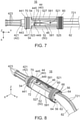
Fig. 7 is a plane view showing the contact assembly ofFig. 6 . -
Fig. 8 is a rear, perspective view showing the contact assembly ofFig. 6 . -
Fig. 9 is another rear, perspective view showing the contact assembly ofFig. 8 . A sleeve member and the annular member are removed. -
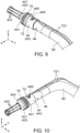
Fig. 10 is a front, perspective view showing the contact assembly ofFig. 9 . -
Fig. 11 is a front, perspective view showing the sleeve member included in the contact assembly ofFig. 6 . -
Fig. 12 is a rear, perspective view showing the sleeve member ofFig. 11 . -
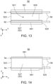
Fig. 13 is a plane view showing the sleeve member ofFig. 11 . -
Fig. 14 is a side view showing the sleeve member ofFig. 11 . -
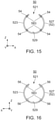
Fig. 15 is a front view showing the sleeve member ofFig. 11 . -
Fig. 16 is a rear view showing the sleeve member ofFig. 11 . -
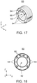
Fig. 17 is a front, perspective view showing the annular member included in the contact assembly ofFig. 6 . -
Fig. 18 is a front view showing the annular member ofFig. 17 . -
Fig. 19 is a side view showing the annular member ofFig. 17 . -
Fig. 20 is an exploded, perspective view showing a connector disclosed in Patent Document 1. -
Fig. 21 is a cross-sectional view showing the connector ofFig. 20 . - While the invention is susceptible to various modifications and alternative forms, specific embodiments thereof are shown by way of example in the drawings and will herein be described in detail. It should be understood, however, that the drawings and detailed description thereto are not intended to limit the invention to the particular form disclosed, but on the contrary, the intention is to cover all modifications, equivalents and alternatives falling within the spirit and scope of the present invention as defined by the appended claims.
- Referring to
Figs. 1 and3 , aconnector 10 according to an embodiment of the present invention is a charging connector for an electric vehicle, wherein it is attached to an end of acable 80. However, the present invention is not limited thereto. The present invention is applicable to connectors for every use. - As shown in
Fig. 1 and3 , theconnector 10 is provided with amating portion 12 and abody 14. Thebody 14 has abase shell 141 and acover shell 143. - As shown in
Figs. 2 and4 , thebase shell 141 is provided withhousings 20. As understood fromFigs. 1 ,3 and 4 , in the present embodiment, the number of thehousings 20 is two. However, the present invention is not limited thereto. The connector of the present invention should be provided with at least onehousing 20. Moreover, thehousings 20 may not be provided to thebase shell 141 but be exposed outside. - As understood from
Figs. 2 and4 ,holders 30 are attached to thehousings 20, respectively. In detail, each of theholders 30 is attached to a rear-end portion of thehousing 20 corresponding thereto. In the present embodiment, a front-rear direction is a Y-direction. A negative Y-direction is directed forward while a positive Y-direction is directed rearward. - As shown in
Fig. 4 , theholder 30 has anend face portion 32 and asidewall portion 34 extending forward from theend face portion 32. Theend face portion 32 is formed with a throughhole 321 piercing theend face portion 32 in the front-rear direction. - As shown in
Fig. 4 , thehousing 20 is formed with acontact accommodation portion 22. Theholder 30 attached to thehousing 20 defines a rear end of thecontact accommodation portion 22 in the front-rear direction. - As shown in
Fig. 4 , in thecontact accommodation portion 22 of thehousing 20, acontact assembly 16 is accommodated. In detail, in thecontact accommodation portion 22, acontact 40, asleeve member 50, anannular member 60, a firstwaterproof member 70 and asensor 72 are accommodated. In other words, theconnector 10 is provided with thecontact 40, thesleeve member 50, theannular member 60, the firstwaterproof member 70 and thesensor 72. However, the present invention is not limited thereto. Theannular member 60, the firstwaterproof member 70 and thesensor 72 are not always necessary. The connector of the present invention should be provided with at least thecontact 40 and thesleeve member 50 in addition to thehousing 20 and theholder 30. - As shown in
Figs. 9 and 10 , thecontact 40 has a multistage cylindrical shape. In detail, thecontact 40 has a connectingportion 42, abarrel portion 44 and awire connection portion 46. The connectingportion 42, thebarrel portion 44 and thewire connection portion 46 are arranged in this order in the front-rear direction so that their central axes are coincide with one another. - As understood from
Figs. 9 and 10 , the connectingportion 42 has abase portion 421 with a cylindrical shape and a plurality ofcontact pieces 423 extending forward from thebase portion 421. Thecontact pieces 423 are arranged at regular intervals in a circumference direction in a plane perpendicular to the front-rear direction. Thecontact pieces 423 are resiliently deformable. Thecontact pieces 423 come into contact with a mating contact (not shown) when theconnector 10 is mated with an inlet (not shown). In the present embodiment, the number of thecontact pieces 423 is eight. However, the present invention is not limited thereto. The connectingportion 42 may be freely designed about its structure and shape. - As understood from
Figs. 9 and 10 , thebarrel portion 44 has an external diameter larger than that of thebase portion 421 of the connectingportion 42. Thebarrel portion 44 has aflange portion 441. An external diameter of theflange portion 441 is larger than that of the other portion of thebarrel portion 44. Theflange portion 441 has a front-end face 443 and a rear-end face 445. As described later, the rear-end face 445 of theflange portion 441 works as an abutment portion. In other words, thecontact 40 is provided with the abutment portion. - As understood from
Figs. 9 and 10 , an outer circumference surface of theflange portion 441 of thecontact 40 is formed with agroove 447 recessed inward. To thegroove 447, the firstwaterproof member 70 is attached. However, the present invention is not limited thereto. If the firstwaterproof member 70 is unnecessary, thegroove 447 is unnecessary either. - As understood from
Figs. 4 ,9 and 10 , thebarrel portion 44 is further formed with ahole 449 with a bottom. Thehole 449 is bored along an up-down direction perpendicular to the front-rear direction. In the present embodiment, the up-down direction is a Z-direction. A positive Z-direction is directed upward while a negative Z-direction is directed downward. In thehole 449, thesensor 72 is inserted and arranged in a lengthwise direction.Wirings 721 of thesensor 72 extend upward from thesensor 72 and are bent at an approximately right angle at an edge of thehole 449. In other words, thewirings 721 of thesensor 72 are bent in the front-rear direction at the edge of thehole 449. Then, thewirings 721 of thesensor 72 extend outside thecontact accommodation portion 22 through the throughhole 321 of theholders 30. In this way, insertion and arrangement of thesensor 72 in thehole 449 formed in the up-down direction perpendicular to the front-rear direction and bending thewirings 721 at the approximately right angle allow a length of thebarrel portion 44 to be reduced in the front-rear direction. Although bent portions of thewirings 721 are slightly rose from thebarrel portion 44, they do not matter because they are located in aslit 521 of thesleeve member 50. In the present embodiment, thesensor 72 is a temperature sensor. However, the present invention is not limited thereto. If thesensor 72 is unnecessary, thehole 449 is unnecessary either. - As understood from
Figs. 4 ,9 and 10 , thewire connection portion 46 has an external diameter smaller than that of thebarrel portion 44. However, the present invention is not limited thereto. The external diameter of thewire connection portion 46 may be equal to the external diameter of thebarrel portion 44. To thewire connection portion 46, anelectrical wire 82 included in thecable 80 is connected. Theelectrical wire 82 connected to thewire connection portion 46 of thecontact 40 extends outside thecontact accommodation portion 22 through the throughhole 321 of theholders 30. - As shown in
Figs. 11 to 14 , thesleeve member 50 has amain portion 52 having a cylindrical shape extending in the front-rear direction. Themain portion 52 has aslit 521 extending in the front-rear direction. In other words, thesleeve member 50 is a split sleeve. Themain portion 52 of thesleeve member 50 has a C-shape section in a plane perpendicular to the front-rear direction. - As shown in
Figs. 11 to 14 , thesleeve member 50 has three or morefront protrusions 54 protruding forward from a front-end face 523 of themain portion 52 in the front-rear direction. In the present embodiment, the number of thefront protrusions 54 is four. - As shown in
Figs. 11 and15 , thefront protrusion 54 has a semicircular section in a plane perpendicular to the front-rear direction. However, the present invention is not limited thereto. The shape of thefront protrusion 54 may be any shape other than the semicircular shape, such as a polygonal shape, a circular shape or an oval shape. - As understood from
Fig. 15 , an arrangement of thefront protrusions 54 has rotational symmetry about a symmetry axis extending in the front-rear direction. This is for making thefront protrusions 54 be brought into abutment with the rear-end face 445 or the abutment portion of theflange portion 441 in a balanced manner when thesleeve member 50 is attached to thecontact 40 as shown inFig. 8 . - As understood from
Fig. 15 , in a direction perpendicular to the front-rear direction and perpendicular to a surface (anouter circumference surface 527 or an inner circumference surface 529) of themain portion 52, a maximum size of thefront protrusion 54 is larger than a size (a thickness) of themain portion 52 at the vicinity thereof. This is for giving necessary strength to thefront protrusion 54. In the present embodiment, when viewed from the front of thesleeve member 50, thefront protrusions 54 protrude radially outward of themain portion 52. However, the present invention is not limited thereto. Thefront protrusions 54 may protrude radially inward of themain portion 52 when viewed from the front of thesleeve member 50. Alternately, thefront protrusions 54 may protrude both radially outward and radially inward of themain portion 52 when viewed from the front of thesleeve member 50. - As shown in
Figs. 11 to 14 , thesleeve member 50 has three or morerear protrusions 56 protruding rearward from a rear-end face 525 of themain portion 52 in the front-rear direction. In the present embodiment, the number of therear protrusions 56 is four. However, the present invention is not limited thereto. Therear protrusions 56 are not always necessary. Nevertheless, it is preferable to have therear protrusions 56 in a case where theannular member 60 has resilience, for example, theannular member 60 is a second waterproof member. This is for ensuring regulation of rearward movement of thecontact 40 with respect to thehousing 20. - As shown in
Figs. 12 and16 , therear protrusion 56 has a circular shape section in a plane perpendicular to the front-rear direction. However, the present invention is not limited thereto. The shape of therear protrusion 56 may be any shape other than the circular shape, for example, a polygonal shape, a half circular shape or an oval shape. However, it is desirable that a cross-sectional area of therear protrusion 56 is large to secure strength of therear protrusion 56. - As understood from
Fig. 16 , an arrangement of therear protrusions 56 has rotational symmetry about a symmetry axis extending in the front-rear direction. This is for making therear protrusions 56 be brought into abutment with theend face portion 32 of theholder 30 in a balanced manner. - As understood from
Fig. 16 , in the direction perpendicular to the front-rear direction and perpendicular to the surface (theouter circumference surface 527 or the inner circumference surface 529) of themain portion 52, a maximum size of therear protrusion 56 is larger than a size (a thickness) of themain portion 52 at the vicinity thereof. In the present embodiment, when viewed from behind thesleeve member 50, therear protrusions 56 protrude both radially outward and radially inward of themain portion 52. However, the present invention is not limited thereto. When viewed from behind thesleeve member 50, therear protrusions 56 may protrude either radially inward or radially outward of themain portion 52. - As understood from
Figs. 11 to 16 , thefront protrusions 54 correspond to therear protrusions 56, respectively. On theouter circumference surface 527 of themain portion 52, outerelongated protrusions 581 coupling thefront protrusions 54 with therear protrusions 56 corresponding to thefront protrusions 54, respectively, in the front-rear direction are provided. The outerelongated protrusions 581 protrude radially outward from theouter circumference surface 527 of themain portion 52. Although the outerelongated protrusions 581 are not always necessary, they can give strength to thesleeve member 50. - As understood from
Figs. 11 and 12 , theinner circumference surface 529 of themain portion 52 is provided with innerelongated protrusions 583 continuous with therear protrusions 56. The innerelongated protrusions 583 protrude radially inward from theinner circumference surface 529 of themain portion 52. The innerelongated protrusions 583 extend forward to the middle of themain portion 52 in the front-rear direction. This is in consideration of a difference between the external diameter of thebarrel portion 44 of thecontact 40 and the external diameter of thewire connection portion 46. However, the present invention is not limited thereto. The innerelongated protrusions 583 may extend to thefront protrusions 54. In that case, provided that enough strength can be secured for thesleeve member 50, the outerelongated protrusions 581 may not be provided. At any rate, it is preferable to provide an elongated protrusion coupling each of thefront protrusions 54 with therear protrusion 56 corresponding to thefront protrusion 54 in the front-rear direction on at least one of theouter circumference surface 527 and theinner circumference surface 529 of themain portion 52. - Referring to
Figs. 17 to 19 , in the present embodiment, theannular member 60 is the second waterproof member. In other words, in the present embodiment, theconnector 10 is provided with the second waterproof member. In detail, theannular member 60 is formed with synthetic rubber to have a bellows shape. With this structure, theannular member 60 is resiliently deformable in the front-rear direction and resiliently deformable in radial directions. - As shown in
Figs. 17 and 18 , theannular member 60 is formed with three or more throughholes 64 and one or more additional throughholes 66 which pierce theannular member 60 in the front-rear direction in addition to acentral hole 62. The through holes 64 correspond to therear protrusions 56 of thesleeve member 50. In the present embodiment, the number of the throughholes 64 is four. The additional throughholes 66 correspond to thewirings 721 of thesensor 72. In the present embodiment, the number of the additional throughholes 66 is two. However, the present invention is not limited thereto. The number of the throughholes 64 depends on the number of therear protrusions 56, and the number of the additional throughholes 66 depends on the number of thewirings 721. - As shown in
Figs. 6 to 8 , thecontact 40, thesleeve member 50 and theannular member 60 are combined with one another to form thecontact assembly 16. - As understood from
Figs. 6 to 8 , thesleeve member 50 is attached to thecontact 40. At that time, a part of thecontact 40 and a part of theelectrical wire 82 are accommodated in themain portion 52 of thesleeve member 50. In detail, as shown inFig. 4 , thesleeve member 50 is located rearward of theflange portion 441 of thecontact 40 in the front-rear direction. And, a part of thebarrel portion 44 of thecontact 40 and thewire connection portion 46 are located in themain portion 52 of thesleeve member 50. Thewirings 721 of thesensor 72 are located in theslit 521 in part. Further, thewirings 721 pass through theslit 521 and extend rearward. - As shown in
Figs. 6 to 8 , theannular member 60 is attached to thesleeve member 50. At that time, therear protrusions 56 of thesleeve member 50 are inserted into the throughholes 64 of theannular member 60 that correspond to them, respectively. Moreover, thewirings 721 of thesensor 72 pass through the additional throughholes 66 of theannular member 60 that correspond to them and extend rearward. - As understood from
Fig. 4 , when thecontact assembly 16 is accommodated in thehousing 20, the firstwaterproof member 70 is sandwiched between theflange portion 441 of thecontact 40 and thehousing 20. Then, the firstwaterproof member 70 prevents water entering thecontact accommodation portion 22 from the front thereof from reaching thesensor 72 or thewire connection portion 46. The firstwaterproof member 70 is made of synthetic rubber and has an annular shape. - As shown in
Fig. 4 , when thecontact 40 is accommodated in thehousing 20, the front-end face 443 of theflange portion 441 is brought into contact with anabutment surface 24 of thehousing 20. Accordingly, forward movement of thecontact 40 with respect to thehousing 20 is regulated. In the present embodiment, the whole of thecontact 40 is located in thehousing 20. However, the present invention is not limited thereto. Thecontact 40 should be accommodated in thecontact accommodation portion 22 of thehousing 20 at least in part. For example, the connectingportion 42 may protrude forward from thehousing 20 in part. - As shown in
Fig. 4 , thesleeve member 50 is located between theflange portion 441 of thecontact 40 and theholder 30 in the front-rear direction when it is accommodated in thecontact accommodation portion 22 of thehousings 20. In detail, thesleeve member 50 is located between the rear-end face 445 of theflange portion 441, i.e. the abutment portion, and theend face portion 32 of theholder 30. At that time, thefront protrusions 54 are brought into abutment with the rear-end face 445 of theflange portion 441. Thus, the rear-end face 445 of theflange portion 441 works as the abutment portion with which thefront protrusions 54 are brought into abutment. - It is desirable that protruding dimensions of the
front protrusions 54 are equal to one another. However, there is a case where the protruding dimensions of thefront protrusions 54 are different from one another due to production variation. In that case, if differences among the protruding dimensions of thefront protrusions 54 are within a permissible range, at least three of thefront protrusions 54 are brought into abutment with the rear-end face 445. In a case where the differences among the protruding dimensions of thefront protrusions 54 are out of the permissible range, the number of thefront protrusions 54 which are brought into abutment with the rear-end face 445 may be one or two so that positional relationship between thecontact 40 and thesleeve member 50 may be unstable. In addition, there is a possibility that thefront protrusions 54 are damaged. Accordingly, in the case where the differences among the protruding dimensions of thefront protrusions 54 are out of the permissible range, the protruding amounts of thefront protrusions 54 must be adjusted. This adjustment of the protruding amounts of thefront protrusions 54 may be made to a mold which is used to manufacture thesleeve member 50. This adjustment is remarkably easier than adjustment for a mold which is used for manufacturing thesleeve member 940 of Patent Document 1. In other words, the adjustment of the protruding amounts of thefront protrusions 54 is remarkably easier than adjusting a tilt of the whole of the front-end surface of thesleeve member 940 of Patent Document 1. - As understood from
Fig. 5 , when thesleeve member 50 is accommodated in thecontact accommodation portion 22 of thehousing 20, therear protrusions 56 of thesleeve member 50 are brought into abutment with theend face portion 32 of theholder 30. At that time, if differences among protruding amounts of therear protrusions 56 are within a permissible range, at least three of therear protrusions 56 are brought into abutment with theend face portion 32. Similarly to the case of thefront protrusions 54, in the case where the differences among the protruding dimensions of therear protrusions 56 are out of the permissible range, the protruding amounts of therear protrusions 56 must be adjusted. Also in this case, the adjustment of the protruding amounts of therear protrusions 56 is remarkably easier than adjusting a tilt of the whole of the rear-end surface of thesleeve member 940 of Patent Document 1. - As understood from
Fig. 5 , thesleeve member 50 is sandwiched between thecontact 40 and theholder 30. And, thefront protrusions 54 are brought into abutment with the rear-end face 445 of theflange portion 441, and therear protrusions 56 are brought into abutment with theend face portion 32 of theholder 30. Thus, thesleeve member 50 regulates rearward movement of thecontact 40 with respect to thehousing 20. However, the present invention is not limited thereto. In a case where thesleeve member 50 does not have therear protrusions 56, themain portion 52 of thesleeve member 50 may be brought into abutment with theholder 30 directly or via theannular member 60. In a case where theannular member 60 is used, it is necessary that theannular member 60 has a predetermined strength in the front-rear direction. - As shown in
Fig. 4 , theannular member 60 is located between themain portion 52 of thesleeve member 50 and theholder 30 in the front-rear direction when it is accommodated in thecontact accommodation portion 22 of thehousing 20. In detail, thesleeve member 50 is sandwiched between the rear-end face 525 of themain portion 52 of thesleeve member 50 and theend face portion 32 of theholder 30. In the present embodiment, theannular member 60 is sandwiched between theelectrical wire 82 and thehousing 20 and prevents water from entering thecontact accommodation portion 22 from behind thecontact accommodation portion 22. However, the present invention is not limited thereto. Theannular member 60 may not have a waterproof purpose but be a thing having a purpose for preventing the rearward movement of themain portion 52 of thesleeve member 50 with respect to theholder 30 in place of therear protrusions 56 of thesleeve member 50. - Although the specific explanation about the present invention is made above referring to the embodiments, the present invention is not limited thereto but susceptible of various modifications.
- For example, although the number of the
electrical wire 82 connected to thewire connection portion 46 of thecontact 40 is one in the aforementioned embodiment, the number ofelectrical wires 82 connected to thewire connection portion 46 may be two or more. In that case, a member which has a plurality of through holes corresponding to the plurality of theelectrical wires 82 instead of thecentral hole 62 may be used in place of theannular member 60. - While there has been described what is believed to be the preferred embodiment of the invention, those skilled in the art will recognize that other and further modifications may be made thereto without departing from the spirit of the invention, and it is intended to claim all such embodiments that fall within the true scope of the invention.
Claims (12)
- A connector comprising a housing, a holder, a contact, an electrical wire and a sleeve member, wherein:the housing is formed with a contact accommodation portion;the contact is accommodated in the contact accommodation portion at least in part;the holder is attached to the housing and defines a rear end of the contact accommodation portion in a front-rear direction;the holder is formed with a through hole piercing thereof in the front-rear direction;the electrical wire is connected to the contact and extends from the contact accommodation portion to an outside of the contact accommodation portion through the through hole of the holder;the contact is provided with an abutment portion;the sleeve member has a main portion and three or more front protrusions;the main portion extends in the front-rear direction and has a C-shape section on a plane perpendicular to the front-rear direction;each of the front protrusions protrudes forward from a front end of the main portion in the front-rear direction;the sleeve member is attached to the contact so as to accommodate a part of the contact and a part of the electrical wire in the main portion and located between the abutment portion and the holder in the front-rear direction; andat least three of the front protrusions are brought into abutment with the abutment portion.
- The connector as recited in claim 1, wherein in a direction perpendicular to the front-rear direction and to a surface of the main portion of the sleeve member, a maximum size of each of the front protrusions is larger than a size of the main portion in a vicinity of the front protrusion.
- The connector as recited in claim 1 or 2, wherein:the sleeve member has three or more rear protrusions protruding rearward from the main portion in the front-rear direction; andat least three of the rear protrusions are brought into abutment with the holder.
- The connector as recited in claim 3, wherein:the connector further comprises an annular member;the annular member is located between the rear end of the main portion of the sleeve member and the holder in the contact accommodation portion;the annular member is formed with three or more through holes piercing thereof in the front-rear direction;the through holes of the annular member correspond to the rear protrusions, respectively; andeach of the rear protrusions is inserted in the through hole corresponding thereto.
- The connector as recited in claim 3 or 4, wherein:the front protrusions correspond to the rear protrusions, respectively;the main portion of the sleeve member is formed with an elongated ridge which couples each of the front protrusions with the rear protrusion corresponding the front protrusion in the front-rear direction; andthe elongated ridge protrudes from a surface of the main portion of the sleeve member.
- The connector as recited in any one of claims 3 to 5, wherein an arrangement of the rear protrusions has rotation symmetry about a symmetry axis extending in the front-rear direction.
- The connector as recited in any one of claims 1 to 6, wherein an arrangement of the front protrusions has rotation symmetry about a symmetry axis extending in the front-rear direction.
- The connector as recited in any one of claims 1 to 7, wherein:the connector comprises a first waterproof member and a second waterproof member;the first waterproof member and the second waterproof member are located in the contact accommodation portion;the contact has a flange;the flange is formed with a groove recessed inward in a circumference surface thereof;the first waterproof member is attached in the groove; andthe second waterproof member is sandwiched between a rear end of the main portion of the sleeve member and the holder.
- The connector as recited in claim 8, wherein:the second waterproof member has an annular shape;the second waterproof member is formed with three or more through holes piercing thereof in the front-rear direction;the sleeve member has three or more rear protrusions protruding rearward from the rear end of the main portion in the front-rear direction;the through holes of the second waterproof member correspond to the rear protrusions, respectively; andeach of the rear protrusions is inserted in the through hole corresponding thereto.
- The connector as recited in claim 8 or 9, wherein:the connector further comprises a sensor;a wiring of the sensor is arranged in a slit portion of the sleeve member; andthe wiring of the sensor extends rearward though an additional through hole formed in the second waterproof member and the through hole of the holder.
- The connector as recited in claim 10, wherein:the contact is formed with a hole bored in a direction perpendicular to the front-rear direction;the sensor is longitudinally inserted and arranged in the hole; andthe wiring of the sensor is curved toward in the front-rear direction at an edge of the hole.
- The connector as recited in any one of claims 8 to 11, wherein:the electrical wire connected to the contact is one in number; andeach of the first waterproof member and the second waterproof member has an annular shape.
Applications Claiming Priority (1)
| Application Number | Priority Date | Filing Date | Title |
|---|---|---|---|
| US202063080173P | 2020-09-18 | 2020-09-18 |
Publications (2)
| Publication Number | Publication Date |
|---|---|
| EP3972060A1 true EP3972060A1 (en) | 2022-03-23 |
| EP3972060B1 EP3972060B1 (en) | 2022-10-05 |
Family
ID=77021091
Family Applications (1)
| Application Number | Title | Priority Date | Filing Date |
|---|---|---|---|
| EP21186848.4A Active EP3972060B1 (en) | 2020-09-18 | 2021-07-21 | Connector |
Country Status (5)
| Country | Link |
|---|---|
| US (1) | US11342706B2 (en) |
| EP (1) | EP3972060B1 (en) |
| JP (1) | JP2022051502A (en) |
| CN (1) | CN114194044B (en) |
| ES (1) | ES2929836T3 (en) |
Families Citing this family (3)
| Publication number | Priority date | Publication date | Assignee | Title |
|---|---|---|---|---|
| JP6724857B2 (en) * | 2017-05-11 | 2020-07-15 | 住友電装株式会社 | connector |
| EP3939129A4 (en) * | 2019-03-15 | 2022-12-14 | CommScope Technologies LLC | Connectors and contacts for a single twisted pair of conductors |
| USD1002543S1 (en) * | 2021-09-29 | 2023-10-24 | Jiangsu Yihang Electric Technology Co., Ltd. | DC charging gun |
Citations (2)
| Publication number | Priority date | Publication date | Assignee | Title |
|---|---|---|---|---|
| JP2010055809A (en) | 2008-08-26 | 2010-03-11 | Yazaki Corp | Connector |
| DE102012024588A1 (en) * | 2012-12-17 | 2014-06-18 | HARTING Automotive GmbH | Car charger plug |
Family Cites Families (14)
| Publication number | Priority date | Publication date | Assignee | Title |
|---|---|---|---|---|
| DE102009044179A1 (en) * | 2009-10-05 | 2010-12-30 | Rema Lipprandt Gmbh & Co. Kg | Power supply connector part for use in charging connector for electric vehicle, has locking device connected with position sensor such that current circuit through charging connector is interrupted during operation of locking device |
| DE102010035868B3 (en) * | 2010-08-30 | 2012-02-16 | Phoenix Contact Gmbh & Co. Kg | Electrical component |
| KR20120025837A (en) * | 2010-09-08 | 2012-03-16 | 엘에스전선 주식회사 | Connector for charging an electric car |
| JP5875136B2 (en) | 2011-03-04 | 2016-03-02 | 矢崎総業株式会社 | connector |
| US9597967B2 (en) * | 2011-07-19 | 2017-03-21 | Siemens Industry, Inc. | Status indicating electric vehicle charging station, lightguide assembly and methods |
| DE102013213336B4 (en) * | 2013-07-08 | 2024-02-01 | Te Connectivity Germany Gmbh | ELECTRICAL CONNECTOR, CHARGING SOCKET AND CONNECTOR SYSTEM FOR AN ELECTRIC OR HYBRID VEHICLE |
| JP2016012422A (en) | 2014-06-27 | 2016-01-21 | 住友電装株式会社 | connector |
| JP2016197541A (en) | 2015-04-03 | 2016-11-24 | 住友電装株式会社 | connector |
| JP2017016999A (en) | 2015-07-01 | 2017-01-19 | 住友電装株式会社 | Connection terminal module |
| DE102016122616A1 (en) * | 2016-11-23 | 2018-05-24 | Te Connectivity Germany Gmbh | Power plug and charging system for a motor vehicle |
| JP2018156896A (en) | 2017-03-21 | 2018-10-04 | 住友電装株式会社 | Terminal and connector |
| CN108199191A (en) * | 2017-12-28 | 2018-06-22 | 友邦电气(平湖)股份有限公司 | A kind of charging gun of fast assembling-disassembling |
| JP2019192482A (en) | 2018-04-25 | 2019-10-31 | 矢崎総業株式会社 | Charge connector |
| CN111478117A (en) * | 2020-05-18 | 2020-07-31 | 深圳市沃尔新能源电气科技股份有限公司 | Charging gun |
-
2021
- 2021-02-23 US US17/182,336 patent/US11342706B2/en active Active
- 2021-05-19 JP JP2021084676A patent/JP2022051502A/en active Pending
- 2021-07-21 EP EP21186848.4A patent/EP3972060B1/en active Active
- 2021-07-21 ES ES21186848T patent/ES2929836T3/en active Active
- 2021-07-29 CN CN202110862205.0A patent/CN114194044B/en active Active
Patent Citations (2)
| Publication number | Priority date | Publication date | Assignee | Title |
|---|---|---|---|---|
| JP2010055809A (en) | 2008-08-26 | 2010-03-11 | Yazaki Corp | Connector |
| DE102012024588A1 (en) * | 2012-12-17 | 2014-06-18 | HARTING Automotive GmbH | Car charger plug |
Also Published As
| Publication number | Publication date |
|---|---|
| CN114194044A (en) | 2022-03-18 |
| EP3972060B1 (en) | 2022-10-05 |
| ES2929836T3 (en) | 2022-12-02 |
| US20220094103A1 (en) | 2022-03-24 |
| US11342706B2 (en) | 2022-05-24 |
| CN114194044B (en) | 2023-08-01 |
| JP2022051502A (en) | 2022-03-31 |
Similar Documents
| Publication | Publication Date | Title |
|---|---|---|
| EP3972060A1 (en) | Connector | |
| US6042432A (en) | Terminal for charging with large current | |
| US8002574B1 (en) | RF module with a housing with spring loaded connectors and a strain relief extending rearward of the housing | |
| US20080188120A1 (en) | Connector | |
| JP6855280B2 (en) | Holding member | |
| US5857879A (en) | Female terminal for large current | |
| US10236596B2 (en) | Connection terminal | |
| JP2008052976A (en) | Connector connecting structure | |
| US5620347A (en) | Contact portion structure of female connector terminal | |
| JP4547282B2 (en) | Connector for automatic alignment | |
| EP1859994B1 (en) | Connector and mirror angle adjustment device | |
| US20090104802A1 (en) | Electrical connector assembly | |
| US5324208A (en) | Waterproof connector | |
| JP2009104944A (en) | Latch metal fitting, connector housing with latch metal fitting, and connector with latch metal fitting | |
| US6086419A (en) | Electrical connector assembly | |
| JP2010113962A (en) | Socket terminal | |
| US11749930B2 (en) | Joint connecter having an isolation terminal and connection terminal | |
| CN114267976A (en) | Connector with a locking member | |
| US10644426B2 (en) | Connector | |
| US20230033701A1 (en) | Connector | |
| JP2009059500A (en) | Coaxial connector and terminal for coaxial connector used for this | |
| US20230093051A1 (en) | Male connector and connector assembly | |
| JP7442274B2 (en) | Connectors and wires with connectors | |
| US11909138B2 (en) | Terminal assembly including flat surface formed and aligned for achieving flat contact with mating tab | |
| US20240079824A1 (en) | Electrical connector and electrical connector assembly |
Legal Events
| Date | Code | Title | Description |
|---|---|---|---|
| PUAI | Public reference made under article 153(3) epc to a published international application that has entered the european phase |
Free format text: ORIGINAL CODE: 0009012 |
|
| STAA | Information on the status of an ep patent application or granted ep patent |
Free format text: STATUS: THE APPLICATION HAS BEEN PUBLISHED |
|
| STAA | Information on the status of an ep patent application or granted ep patent |
Free format text: STATUS: REQUEST FOR EXAMINATION WAS MADE |
|
| AK | Designated contracting states |
Kind code of ref document: A1 Designated state(s): AL AT BE BG CH CY CZ DE DK EE ES FI FR GB GR HR HU IE IS IT LI LT LU LV MC MK MT NL NO PL PT RO RS SE SI SK SM TR |
|
| 17P | Request for examination filed |
Effective date: 20220218 |
|
| RBV | Designated contracting states (corrected) |
Designated state(s): AL AT BE BG CH CY CZ DE DK EE ES FI FR GB GR HR HU IE IS IT LI LT LU LV MC MK MT NL NO PL PT RO RS SE SI SK SM TR |
|
| GRAP | Despatch of communication of intention to grant a patent |
Free format text: ORIGINAL CODE: EPIDOSNIGR1 |
|
| STAA | Information on the status of an ep patent application or granted ep patent |
Free format text: STATUS: GRANT OF PATENT IS INTENDED |
|
| INTG | Intention to grant announced |
Effective date: 20220428 |
|
| GRAS | Grant fee paid |
Free format text: ORIGINAL CODE: EPIDOSNIGR3 |
|
| GRAA | (expected) grant |
Free format text: ORIGINAL CODE: 0009210 |
|
| STAA | Information on the status of an ep patent application or granted ep patent |
Free format text: STATUS: THE PATENT HAS BEEN GRANTED |
|
| AK | Designated contracting states |
Kind code of ref document: B1 Designated state(s): AL AT BE BG CH CY CZ DE DK EE ES FI FR GB GR HR HU IE IS IT LI LT LU LV MC MK MT NL NO PL PT RO RS SE SI SK SM TR |
|
| REG | Reference to a national code |
Ref country code: GB Ref legal event code: FG4D |
|
| REG | Reference to a national code |
Ref country code: CH Ref legal event code: EP |
|
| REG | Reference to a national code |
Ref country code: AT Ref legal event code: REF Ref document number: 1523344 Country of ref document: AT Kind code of ref document: T Effective date: 20221015 |
|
| REG | Reference to a national code |
Ref country code: IE Ref legal event code: FG4D |
|
| REG | Reference to a national code |
Ref country code: DE Ref legal event code: R096 Ref document number: 602021000511 Country of ref document: DE |
|
| REG | Reference to a national code |
Ref country code: ES Ref legal event code: FG2A Ref document number: 2929836 Country of ref document: ES Kind code of ref document: T3 Effective date: 20221202 |
|
| REG | Reference to a national code |
Ref country code: LT Ref legal event code: MG9D |
|
| REG | Reference to a national code |
Ref country code: NL Ref legal event code: MP Effective date: 20221005 |
|
| REG | Reference to a national code |
Ref country code: AT Ref legal event code: MK05 Ref document number: 1523344 Country of ref document: AT Kind code of ref document: T Effective date: 20221005 |
|
| PG25 | Lapsed in a contracting state [announced via postgrant information from national office to epo] |
Ref country code: NL Free format text: LAPSE BECAUSE OF FAILURE TO SUBMIT A TRANSLATION OF THE DESCRIPTION OR TO PAY THE FEE WITHIN THE PRESCRIBED TIME-LIMIT Effective date: 20221005 |
|
| PG25 | Lapsed in a contracting state [announced via postgrant information from national office to epo] |
Ref country code: SE Free format text: LAPSE BECAUSE OF FAILURE TO SUBMIT A TRANSLATION OF THE DESCRIPTION OR TO PAY THE FEE WITHIN THE PRESCRIBED TIME-LIMIT Effective date: 20221005 Ref country code: PT Free format text: LAPSE BECAUSE OF FAILURE TO SUBMIT A TRANSLATION OF THE DESCRIPTION OR TO PAY THE FEE WITHIN THE PRESCRIBED TIME-LIMIT Effective date: 20230206 Ref country code: NO Free format text: LAPSE BECAUSE OF FAILURE TO SUBMIT A TRANSLATION OF THE DESCRIPTION OR TO PAY THE FEE WITHIN THE PRESCRIBED TIME-LIMIT Effective date: 20230105 Ref country code: LT Free format text: LAPSE BECAUSE OF FAILURE TO SUBMIT A TRANSLATION OF THE DESCRIPTION OR TO PAY THE FEE WITHIN THE PRESCRIBED TIME-LIMIT Effective date: 20221005 Ref country code: FI Free format text: LAPSE BECAUSE OF FAILURE TO SUBMIT A TRANSLATION OF THE DESCRIPTION OR TO PAY THE FEE WITHIN THE PRESCRIBED TIME-LIMIT Effective date: 20221005 Ref country code: AT Free format text: LAPSE BECAUSE OF FAILURE TO SUBMIT A TRANSLATION OF THE DESCRIPTION OR TO PAY THE FEE WITHIN THE PRESCRIBED TIME-LIMIT Effective date: 20221005 |
|
| PG25 | Lapsed in a contracting state [announced via postgrant information from national office to epo] |
Ref country code: RS Free format text: LAPSE BECAUSE OF FAILURE TO SUBMIT A TRANSLATION OF THE DESCRIPTION OR TO PAY THE FEE WITHIN THE PRESCRIBED TIME-LIMIT Effective date: 20221005 Ref country code: PL Free format text: LAPSE BECAUSE OF FAILURE TO SUBMIT A TRANSLATION OF THE DESCRIPTION OR TO PAY THE FEE WITHIN THE PRESCRIBED TIME-LIMIT Effective date: 20221005 Ref country code: LV Free format text: LAPSE BECAUSE OF FAILURE TO SUBMIT A TRANSLATION OF THE DESCRIPTION OR TO PAY THE FEE WITHIN THE PRESCRIBED TIME-LIMIT Effective date: 20221005 Ref country code: IS Free format text: LAPSE BECAUSE OF FAILURE TO SUBMIT A TRANSLATION OF THE DESCRIPTION OR TO PAY THE FEE WITHIN THE PRESCRIBED TIME-LIMIT Effective date: 20230205 Ref country code: HR Free format text: LAPSE BECAUSE OF FAILURE TO SUBMIT A TRANSLATION OF THE DESCRIPTION OR TO PAY THE FEE WITHIN THE PRESCRIBED TIME-LIMIT Effective date: 20221005 Ref country code: GR Free format text: LAPSE BECAUSE OF FAILURE TO SUBMIT A TRANSLATION OF THE DESCRIPTION OR TO PAY THE FEE WITHIN THE PRESCRIBED TIME-LIMIT Effective date: 20230106 |
|
| REG | Reference to a national code |
Ref country code: DE Ref legal event code: R097 Ref document number: 602021000511 Country of ref document: DE |
|
| PG25 | Lapsed in a contracting state [announced via postgrant information from national office to epo] |
Ref country code: SM Free format text: LAPSE BECAUSE OF FAILURE TO SUBMIT A TRANSLATION OF THE DESCRIPTION OR TO PAY THE FEE WITHIN THE PRESCRIBED TIME-LIMIT Effective date: 20221005 Ref country code: RO Free format text: LAPSE BECAUSE OF FAILURE TO SUBMIT A TRANSLATION OF THE DESCRIPTION OR TO PAY THE FEE WITHIN THE PRESCRIBED TIME-LIMIT Effective date: 20221005 Ref country code: EE Free format text: LAPSE BECAUSE OF FAILURE TO SUBMIT A TRANSLATION OF THE DESCRIPTION OR TO PAY THE FEE WITHIN THE PRESCRIBED TIME-LIMIT Effective date: 20221005 Ref country code: DK Free format text: LAPSE BECAUSE OF FAILURE TO SUBMIT A TRANSLATION OF THE DESCRIPTION OR TO PAY THE FEE WITHIN THE PRESCRIBED TIME-LIMIT Effective date: 20221005 Ref country code: CZ Free format text: LAPSE BECAUSE OF FAILURE TO SUBMIT A TRANSLATION OF THE DESCRIPTION OR TO PAY THE FEE WITHIN THE PRESCRIBED TIME-LIMIT Effective date: 20221005 |
|
| PLBE | No opposition filed within time limit |
Free format text: ORIGINAL CODE: 0009261 |
|
| STAA | Information on the status of an ep patent application or granted ep patent |
Free format text: STATUS: NO OPPOSITION FILED WITHIN TIME LIMIT |
|
| PG25 | Lapsed in a contracting state [announced via postgrant information from national office to epo] |
Ref country code: SK Free format text: LAPSE BECAUSE OF FAILURE TO SUBMIT A TRANSLATION OF THE DESCRIPTION OR TO PAY THE FEE WITHIN THE PRESCRIBED TIME-LIMIT Effective date: 20221005 Ref country code: AL Free format text: LAPSE BECAUSE OF FAILURE TO SUBMIT A TRANSLATION OF THE DESCRIPTION OR TO PAY THE FEE WITHIN THE PRESCRIBED TIME-LIMIT Effective date: 20221005 |
|
| 26N | No opposition filed |
Effective date: 20230706 |
|
| PGFP | Annual fee paid to national office [announced via postgrant information from national office to epo] |
Ref country code: IT Payment date: 20230731 Year of fee payment: 3 Ref country code: ES Payment date: 20230821 Year of fee payment: 3 |
|
| PG25 | Lapsed in a contracting state [announced via postgrant information from national office to epo] |
Ref country code: SI Free format text: LAPSE BECAUSE OF FAILURE TO SUBMIT A TRANSLATION OF THE DESCRIPTION OR TO PAY THE FEE WITHIN THE PRESCRIBED TIME-LIMIT Effective date: 20221005 |
|
| PGFP | Annual fee paid to national office [announced via postgrant information from national office to epo] |
Ref country code: DE Payment date: 20230727 Year of fee payment: 3 |
|
| PG25 | Lapsed in a contracting state [announced via postgrant information from national office to epo] |
Ref country code: MC Free format text: LAPSE BECAUSE OF FAILURE TO SUBMIT A TRANSLATION OF THE DESCRIPTION OR TO PAY THE FEE WITHIN THE PRESCRIBED TIME-LIMIT Effective date: 20221005 |
|
| PG25 | Lapsed in a contracting state [announced via postgrant information from national office to epo] |
Ref country code: MC Free format text: LAPSE BECAUSE OF FAILURE TO SUBMIT A TRANSLATION OF THE DESCRIPTION OR TO PAY THE FEE WITHIN THE PRESCRIBED TIME-LIMIT Effective date: 20221005 |
|
| REG | Reference to a national code |
Ref country code: BE Ref legal event code: MM Effective date: 20230731 |
|
| PG25 | Lapsed in a contracting state [announced via postgrant information from national office to epo] |
Ref country code: LU Free format text: LAPSE BECAUSE OF NON-PAYMENT OF DUE FEES Effective date: 20230721 |
|
| PG25 | Lapsed in a contracting state [announced via postgrant information from national office to epo] |
Ref country code: LU Free format text: LAPSE BECAUSE OF NON-PAYMENT OF DUE FEES Effective date: 20230721 |