EP3972050A1 - Antenna assembly and electronic device - Google Patents
Antenna assembly and electronic device Download PDFInfo
- Publication number
- EP3972050A1 EP3972050A1 EP20834706.2A EP20834706A EP3972050A1 EP 3972050 A1 EP3972050 A1 EP 3972050A1 EP 20834706 A EP20834706 A EP 20834706A EP 3972050 A1 EP3972050 A1 EP 3972050A1
- Authority
- EP
- European Patent Office
- Prior art keywords
- region
- resonant structure
- signal
- phase variation
- wave
- Prior art date
- Legal status (The legal status is an assumption and is not a legal conclusion. Google has not performed a legal analysis and makes no representation as to the accuracy of the status listed.)
- Granted
Links
Images




Classifications
-
- H—ELECTRICITY
- H04—ELECTRIC COMMUNICATION TECHNIQUE
- H04M—TELEPHONIC COMMUNICATION
- H04M1/00—Substation equipment, e.g. for use by subscribers
- H04M1/02—Constructional features of telephone sets
- H04M1/0202—Portable telephone sets, e.g. cordless phones, mobile phones or bar type handsets
- H04M1/026—Details of the structure or mounting of specific components
-
- H—ELECTRICITY
- H01—ELECTRIC ELEMENTS
- H01Q—ANTENNAS, i.e. RADIO AERIALS
- H01Q15/00—Devices for reflection, refraction, diffraction or polarisation of waves radiated from an antenna, e.g. quasi-optical devices
- H01Q15/02—Refracting or diffracting devices, e.g. lens, prism
-
- H—ELECTRICITY
- H01—ELECTRIC ELEMENTS
- H01Q—ANTENNAS, i.e. RADIO AERIALS
- H01Q1/00—Details of, or arrangements associated with, antennas
- H01Q1/12—Supports; Mounting means
- H01Q1/22—Supports; Mounting means by structural association with other equipment or articles
-
- H—ELECTRICITY
- H01—ELECTRIC ELEMENTS
- H01Q—ANTENNAS, i.e. RADIO AERIALS
- H01Q1/00—Details of, or arrangements associated with, antennas
- H01Q1/12—Supports; Mounting means
- H01Q1/22—Supports; Mounting means by structural association with other equipment or articles
- H01Q1/2258—Supports; Mounting means by structural association with other equipment or articles used with computer equipment
- H01Q1/2266—Supports; Mounting means by structural association with other equipment or articles used with computer equipment disposed inside the computer
-
- H—ELECTRICITY
- H01—ELECTRIC ELEMENTS
- H01Q—ANTENNAS, i.e. RADIO AERIALS
- H01Q1/00—Details of, or arrangements associated with, antennas
- H01Q1/12—Supports; Mounting means
- H01Q1/22—Supports; Mounting means by structural association with other equipment or articles
- H01Q1/24—Supports; Mounting means by structural association with other equipment or articles with receiving set
- H01Q1/241—Supports; Mounting means by structural association with other equipment or articles with receiving set used in mobile communications, e.g. GSM
- H01Q1/242—Supports; Mounting means by structural association with other equipment or articles with receiving set used in mobile communications, e.g. GSM specially adapted for hand-held use
- H01Q1/243—Supports; Mounting means by structural association with other equipment or articles with receiving set used in mobile communications, e.g. GSM specially adapted for hand-held use with built-in antennas
-
- H—ELECTRICITY
- H01—ELECTRIC ELEMENTS
- H01Q—ANTENNAS, i.e. RADIO AERIALS
- H01Q1/00—Details of, or arrangements associated with, antennas
- H01Q1/42—Housings not intimately mechanically associated with radiating elements, e.g. radome
-
- H—ELECTRICITY
- H01—ELECTRIC ELEMENTS
- H01Q—ANTENNAS, i.e. RADIO AERIALS
- H01Q15/00—Devices for reflection, refraction, diffraction or polarisation of waves radiated from an antenna, e.g. quasi-optical devices
- H01Q15/0006—Devices acting selectively as reflecting surface, as diffracting or as refracting device, e.g. frequency filtering or angular spatial filtering devices
- H01Q15/0086—Devices acting selectively as reflecting surface, as diffracting or as refracting device, e.g. frequency filtering or angular spatial filtering devices said selective devices having materials with a synthesized negative refractive index, e.g. metamaterials or left-handed materials
-
- H—ELECTRICITY
- H01—ELECTRIC ELEMENTS
- H01Q—ANTENNAS, i.e. RADIO AERIALS
- H01Q15/00—Devices for reflection, refraction, diffraction or polarisation of waves radiated from an antenna, e.g. quasi-optical devices
- H01Q15/02—Refracting or diffracting devices, e.g. lens, prism
- H01Q15/04—Refracting or diffracting devices, e.g. lens, prism comprising wave-guiding channel or channels bounded by effective conductive surfaces substantially perpendicular to the electric vector of the wave, e.g. parallel-plate waveguide lens
-
- H—ELECTRICITY
- H01—ELECTRIC ELEMENTS
- H01Q—ANTENNAS, i.e. RADIO AERIALS
- H01Q15/00—Devices for reflection, refraction, diffraction or polarisation of waves radiated from an antenna, e.g. quasi-optical devices
- H01Q15/02—Refracting or diffracting devices, e.g. lens, prism
- H01Q15/08—Refracting or diffracting devices, e.g. lens, prism formed of solid dielectric material
-
- H—ELECTRICITY
- H01—ELECTRIC ELEMENTS
- H01Q—ANTENNAS, i.e. RADIO AERIALS
- H01Q19/00—Combinations of primary active antenna elements and units with secondary devices, e.g. with quasi-optical devices, for giving the antenna a desired directional characteristic
- H01Q19/06—Combinations of primary active antenna elements and units with secondary devices, e.g. with quasi-optical devices, for giving the antenna a desired directional characteristic using refracting or diffracting devices, e.g. lens
- H01Q19/062—Combinations of primary active antenna elements and units with secondary devices, e.g. with quasi-optical devices, for giving the antenna a desired directional characteristic using refracting or diffracting devices, e.g. lens for focusing
-
- H—ELECTRICITY
- H01—ELECTRIC ELEMENTS
- H01Q—ANTENNAS, i.e. RADIO AERIALS
- H01Q21/00—Antenna arrays or systems
-
- H—ELECTRICITY
- H01—ELECTRIC ELEMENTS
- H01Q—ANTENNAS, i.e. RADIO AERIALS
- H01Q21/00—Antenna arrays or systems
- H01Q21/0006—Particular feeding systems
-
- H—ELECTRICITY
- H01—ELECTRIC ELEMENTS
- H01Q—ANTENNAS, i.e. RADIO AERIALS
- H01Q21/00—Antenna arrays or systems
- H01Q21/06—Arrays of individually energised antenna units similarly polarised and spaced apart
-
- H—ELECTRICITY
- H01—ELECTRIC ELEMENTS
- H01Q—ANTENNAS, i.e. RADIO AERIALS
- H01Q21/00—Antenna arrays or systems
- H01Q21/06—Arrays of individually energised antenna units similarly polarised and spaced apart
- H01Q21/08—Arrays of individually energised antenna units similarly polarised and spaced apart the units being spaced along or adjacent to a rectilinear path
Definitions
- This disclosure relates to the technical field of electronic technology, and in particular, to an antenna assembly and an electronic device.
- An antenna assembly and an electronic device are provided in implementations of the disclosure, which can improve antenna signal transmission quality and data transmission rate.
- an antenna assembly in the implementations of the present disclosure.
- the antenna assembly includes a dielectric structure and an antenna module.
- the dielectric has a first region, a second region, and a third region connected in sequence.
- the antenna module faces the second region, the antenna module is configured to emit a radio frequency (RF) signal, the first region is configured to bring a first phase variation to the RF signal, the second region is configured to bring a second phase variation to the RF signal, the third region is configured to bring a third phase variation to the RF signal, and the second phase variation is different from the first phase variation and the third phase variation.
- RF radio frequency
- an electronic device in the implementations of the present disclosure.
- the electronic device includes a housing, at least one resonant structure disposed at a partial region of the housing, and at least one millimeter-wave (mm-wave) antenna array.
- Each of the at least one mm-wave antenna array faces one resonant structure, the resonant structure is configured to bring a first phase variation to a RF signal emitted by the mm-wave antenna array, a region of the housing without the resonant structure is configured to bring a second phase variation to the RF signal emitted by the mm-wave antenna array, the first phase variation is greater than the second phase variation, such that the resonant structure increases a gain of the RF signal emitted by the mm-wave antenna array.
- mm-wave millimeter-wave
- the dielectric structure can act as a "lens", which can converge the RF signal emitted by the antenna module to concentrate energy of the RF signal, thereby increasing a gain of the RF signal emitted by the antenna module.
- FIG. 1 is a schematic view illustrating an electronic device from a first view.
- the electronic device 100 may be any products with antenna, such as a tablet computer, a mobile phone, a notebook computer, an in-vehicle equipment, a wearable device, or the like.
- the present disclosure describes the mobile phone as an example of the electronic device 100.
- the electronic device 100 is defined with reference to a first viewing angle. Specifically, a width direction of the electronic device 100 is defined as an X-axis direction, a length direction of the electronic device 100 is defined as a Y-axis direction, and a thickness direction of the electronic device 100 is defined as a Z-axis direction.
- FIG. 2 illustrates an antenna assembly 10 provided in implementations of the present disclosure.
- the antenna assembly 10 includes a dielectric structure 1 and an antenna module 2.
- the dielectric structure 1 has a first region 11, a second region 12, and a third region 13 connected in sequence.
- the antenna module 2 faces the second region 12, the antenna module 2 is configured to receive and emit an electromagnetic wave signal.
- the electromagnetic wave signal received or emitted by the antenna module 2 is referred to as a radio frequency (RF) signal.
- RF radio frequency
- the antenna module 2 is configured to receive and emit a RF signal.
- the first region 11 is configured to bring a first phase variation to the RF signal
- the second region 12 is configured to bring a second phase variation to the RF signal
- the third region 13 is configured to bring a third phase variation to the RF signal
- the second phase variation is different from the first phase variation and the third phase variation.
- the dielectric structure 1 can act as a "lens", which can converge the RF signal emitted by the antenna module 2 to concentrate energy of the RF signal, thereby increasing a gain of the RF signal emitted by the antenna module 2.
- the RF signal is a modulated electromagnetic wave with a certain radiation frequency.
- a transmission frequency band of the RF signal may include, but not limited to, millimeter-wave (mm-wave) frequency band, submillimeter frequency band, or terahertz frequency band.
- the transmission frequency band of the RF signal may include an electromagnetic wave in medium frequency band or low frequency band.
- the antenna module 2 can be any antenna capable of receiving and emitting the electromagnetic wave of mm-wave frequency band, submillimeter frequency band, terahertz frequency band, etc.
- the antenna module 2 includes, but is not limited to, a phased array antenna, etc.
- the mm-wave signal is taken as an example of the RF signal for illustration.
- the dielectric structure 1 as a whole is a substrate capable of making the RF signal pass through, such that the RF signal can be radiated out through the dielectric structure 1.
- the first phase variation brought by the first region 11 to the RF signal represents a difference value between a phase of the RF signal before reaching the first region 11 and a phase of the RF signal after passing through the first region 11.
- the dielectric structure 1 interacts with the RF signal, such that the RF signal has a varied phase after passing through the dielectric structure 1.
- the first region 11 and the second region 12 of the dielectric structure 1 have different effects on the RF signal, therefore, the first region 11 and the second region 12 of the dielectric structure 1 bring different phase variations to the RF signal.
- a RF signal after passing through the first region 11 has a phase the same as or substantially the same as a RF signal after passing through the second region 12, so as to concentrate the energy of the RF signal, and achieve beamforming of the RF signal. In this way, the gain of the RF signal can be increased with aid of the dielectric structure 1.
- the material of the dielectric structure 1 may be locally uneven, such that the dielectric structure 1 can bring different phase variations to the RF signal.
- the dielectric structure 1 is equivalent to a structure in which the first region 11 is made of an even material, the second region 12 is made of an even material, and the third region 13 is made of an even material, the first region 11, the second region 12, and the third region 13 each have a different equivalent dielectric constant.
- the RF signal may have different phase variations when interacting with the first region 11, the second region 12, and the third region 13 respectively.
- the energy of the RF signal can be concentrated, and the beamforming of the RF signal can be achieved. In this way, the gain of the RF signal can be improved with aid of the dielectric structure 1.
- the dielectric structure 1 can act as a "lens" structure of the RF signal.
- the first region 11, the second region 12, and the third region 13 of the dielectric structure 1 each have a different equivalent refractive index to the RF signal.
- the RF signal may have different phase variations when interacting with the first region 11, the second region 12, and the third region 13 respectively, and it is possible to make the RF signal after passing through the first region 11have a phase the same as or substantially the same as the RF signal after passing through the second region 12.
- the energy of the RF signal can be concentrated, and the beamforming of the RF signal can be achieved. In this way, the gain of the RF signal can be improved with aid of the dielectric structure 1.
- the first region 11, the second region 12, and the third region 13 of the dielectric structure 1 can bring different phase variations to the RF signal due to reasons including, but not limited to, different characteristics of transmission materials, different secondary radiation waves generated, etc.
- the manner that the second phase variation is set to be different from the first phase variation and the third phase variation includes, but is not limited to the following.
- the equivalent dielectric constant of the second region 12 is greater than that of the first region 11 and that of the third region 13, such that the second phase variation is greater than the first phase variation and the third phase variation.
- the equivalent refractive index of the second region 12 is less than that of the first region 11 and that of the third region 13, such that the first region 11, the second region 12, and the third region 13 of the dielectric structure 1 is equivalent to a "lens" structure of the RF signal with a large thickness in the middle and a small thickness on both ends.
- a distance between the antenna module 2 and the second region 12 is less than a distance between the antenna module 2 and the first region 11, and also less than a distance between the antenna module 2 and the third region 13, such that a RF signal reaching a surface of the second region 12 from the antenna module 2 has a phase less than a RF signal reaching a surface of the first region 11 from the antenna module 2, and also less than a RF signal reaching a surface of the third region 13 from the antenna module 2.
- the second region 12 brings a greater phase compensation to the RF signal than the first region 11 and the third region 13, such that the RF signal has the same or substantially the same phases after passing through the first region 11, the second region 12, and the third region 13.
- the energy of the RF signal can be concentrated, and the beamforming of the RF signal can be achieved, such that the gain of the RF signal emitted by the antenna module 2 can be increased after the RF signal passes through the dielectric structure 1.
- the equivalent dielectric constant of the first region 11 can be the same as that of the third region 13, such that the first phase variation is the same as the third phase variation.
- the equivalent refractive index of the first region 11 can be the same as that of the third region 13, such that the first region 11, the second region 12, and the third region 13 of the dielectric structure 1 is equivalent to a symmetrical "lens" structure which has a large thickness in the middle and a small thickness on both ends.
- the first phase variation can be the same as the third phase variation, such that the RF signal after passing through the first region 11 and the RF signal after passing through the third region 13 can be symmetrically concentrated toward the second region 12. Furthermore, a main lobe direction of the RF signal after passing through the first region 11 and the RF signal after passing through the third region 13 can be along or approximately along a normal direction of the second region 12. The main lobe refers to a beam with the greatest radiation intensity in the RF signal.
- the equivalent dielectric constant of the first region 11 is different from the third region 13, such that the first phase variation is different from the third phase variation.
- the dielectric structure 1 can bring a phase variation to the RF signal more flexibly, and energy concentration as well as the main lobe direction of the RF signal after passing through the first region 11 and the RF signal after passing the third region 13 can be more flexible, so as to adapt to different designs of the antenna assembly 10.
- the equivalent dielectric constant of the second region 12 is less than that of the first region 11 and the third region 13
- the second phase variation is less than the first phase variation and the third phase variation.
- the equivalent refractive index of the second region 12 is equivalent to a "lens" structure which has a small thickness in the middle and a large thickness on both ends.
- the first phase variation can be the same as or different from the third phase variation, which will not be repeated herein.
- the second phase variation can be less than the first phase variation and the third phase variation, such that the second region 12 brings a less phase compensation to the RF signal than the first region 11 and the third region 13. In this way, the RF signal radiated has a wider spatial coverage and a larger spatial coverage angle.
- the dielectric structure 1 further includes a fourth region disposed at the first region 11 away from the second region 12 and a fifth region disposed at the third region 13 away from the second region 12.
- a phase variation brought by each of the fourth region and the fifth region to the RF signal is different from that brought by each of the first region 11 and the second region 12.
- the phase variation brought by the fourth region to the RF signal is the same as that brought by the fifth region to the RF signal, and the phase variation brought by each of the fourth region and the fifth region to the RF signal is less than that brought by the first region 11 to the RF signal, such that the dielectric structure 1 can bring gradient phase variations to the RF signal in different regions.
- the dielectric structure 1 provided in this implementation is equivalent to a "lens" which has a large thickness in the middle and gradually reduced thickness on both ends, such that radiation of the RF signal emitted by the antenna module 2 is closer to the normal direction of the second region 12, which increases the gain of the RF signal emitted by antenna module 2.
- the second region 12 has a transmittance to the RF signal greater than the first region 11 and the third region 13.
- the second region 12 is provided with a metamaterial structure
- the metamaterial structure can be thought of as molecules and atoms of materials, and the metamaterial structure consists of element structures with a size much smaller than a wavelength.
- an artificial specific electromagnetic medium with a certain number of element structures which are arranged at regular intervals as a whole can be equivalent to a homogeneous medium with certain equivalent electromagnetic parameters.
- the metamaterial structure is an equivalent homogeneous medium with certain thickness and has reflection and transmission coefficients, by adjusting the metamaterial structure, the reflection coefficient can be minimized and the transmission coefficient can be maximized.
- the transmission coefficient of the metamaterial structure to the RF signal can be adjusted to be the same as or substantially the same as the transmission coefficient of air to the RF signal, such that the metamaterial structure has a relatively high transmittance to RF signal.
- the second region 12 is provided with the metamaterial structure, such that the second region 12 has a second transmittance to the RF signal.
- the first region 11 has a first transmittance to the RF signal and the third region 13 has a third transmittance to the RF signal.
- the second region 12 is provided with the metamaterial structure, the second transmittance is greater than the first transmittance and the second transmittance.
- the antenna module 2 faces the second region 12, more RF signals of the antenna module 2 can pass through the second region 12, which is possible to reduce the RF signal loss of the antenna module 2 caused by the dielectric structure 1, and improve radiation efficiency of the antenna module 2.
- the antenna module 2 is applied to the electronic device 100 such as a mobile phone and the RF signal is in the mm-wave frequency band, application and radiation effect of the mm-wave frequency band in the electronic devices 100 such as a mobile phone can be improved.
- the electronic device 100 is a mobile phone.
- the dielectric structure 1 is a battery cover of the electronic device 100.
- the antenna module 2 is disposed in the electronic device 100.
- the antenna module 2 receives and emits the RF signal toward the battery cover to realize communication of the electronic device 100.
- the RF signal can be a mm-wave signal.
- the battery cover of the electronic device 100 is improved by disposing the metamaterial structure at a partial region of the battery cover. A region of the battery cover where the metamaterial structure is disposed serves as the second region 12, and regions of the battery cover on two opposite ends of the metamaterial serve as the first region 11 and the third region 13.
- the metamaterial structure includes, but is not limited to, a one-dimensional, two-dimensional or three-dimensional conductive layer structure.
- the battery cover can exhibit a high radio-wave transmission characteristic to the mm-wave frequency band, and can act as a "mm-wave transparent battery cover" which has a minimum coverage effect (blocking signal radiation) on the mm-wave antenna module 2.
- the battery cover can act as a local "lens” to achieve the beamforming of the mm-wave frequency band signal, and increase the gain of the mm-wave antenna module 2.
- the orthographic projection of antenna module 2 on the dielectric structure 1 falls in the second region 12.
- the second region 12 is at a back surface of the electronic device 100.
- the second region 12 has a size of W 1 in the X-axis direction and a size of L 1 in the Y-axis direction
- the antenna module 2 has a size of W 2 in the X-axis direction and a size of L 2 in the Y-axis direction, where W 1 ⁇ W 2 , and L 1 ⁇ L 2 .
- the second region 12 has a relatively great transmittance to the RF signal, by setting size of the antenna module 2 to be less than that of the second region 12, more RF signals emitted from the antenna module 2 passes through the second region 12, such that the loss of the RF signals can be reduced, and the radiation efficiency of the antenna module 2 can be improved.
- a center of the antenna module 2 is aligned with a center of the second region 12 in an arrangement direction of the first region 11, the second region 12, and the third region 13.
- the antenna module 2 functions as a point emission source.
- the center of the antenna module 2 is in the normal direction of the second region 12, such that after a RF signal radiated by the antenna module 2 passes through the first region 11, the second region 12, and the third region 13, the spherically radiated RF signal can form a plane beam along the normal direction of the second region 12, so as to achieve the beamforming of the RF signal, increase the gain of the RF signal, and optimize performance of the antenna module 2 in free space.
- Improvements to the second region 12 include, but are not limited to, improvements to materials of the second region 12, or provision of the metamaterial structure on the second region 12, such that the phase variation to the RF signal brought by the second region 12 can be greater than that brought by the first region 11 and the third region 13, the gain of the RF signal of the antenna module 2 can be increased with aid of the dielectric structure 1, and application of the antenna assembly 10 in the electronic device 100 such as a mobile phone can be improved.
- the improvements to the second region 12 in the present disclosure include, but are not limited to those provided in the implementation below.
- the dielectric structure 1 includes a housing substrate 14 and a resonant structure 15 disposed at the housing substrate 14.
- a region of the housing substrate 14 where the resonant structure 15 is disposed serves as the second region 12
- a region of the housing substrate 14 at one side of the resonant structure 15 serves as the first region 11
- a region of the housing substrate 14 at the other side of the resonant structure 15 serves as the third region 13.
- the electronic device 100 is a mobile phone, for example.
- the dielectric structure 1 may be a battery cover of the mobile phone.
- the resonant structure 15 is configured to generate a secondary radiation wave under the action of the RF signal, the secondary radiation wave interacts with an incident RF signal to change the phase of the RF signal, such that the second region 12 of the dielectric structure 1 can bring a relatively great phase variation to the RF signal.
- the housing substrate 14 is part of a housing of the electronic device 100, and the housing substrate 14 itself can change the phase of the RF signal due to material loss, surface waves and other effects.
- the phase variation of the housing substrate 14 to the RF signal is less than the phase variation brought by a housing substrate provided with the resonant structure 15 to the RF signal.
- the housing substrate 14 itself brings a less phase variation to the RF signal, such that the dielectric structure 1 can be formed into a structure which can bring a less phase variation, a great phase variation, and a less phase variation in different regions of the dielectric structure 1.
- Such structure of the dielectric structure 1 is similar to a "lens" which has a large thickness in the middle and a small thickness on both sides, so as to achieve beamforming of the RF signal of the antenna module 2, increase a gain of the antenna module 2, and further achieve a wider application of the mm-wave frequency band in the electronic device 100 such as a mobile phone.
- the resonant structure 15 can be disposed at a partial region of the housing substrate 14 in various manners which are not limited herein and can include, but are not limited to, the manners provided in the following implementations.
- the housing substrate 14 has a first surface 141 and a second surface 142 which is opposite to the first surface 141 and faces the antenna module 2.
- the resonant structure 15 is disposed on the first surface 141.
- the housing substrate 14 is the battery cover of the electronic device 100, for example.
- the first surface 141 is an outer surface of the housing substrate 14, and the second surface 142 is an inner surface of the housing substrate 14.
- the resonant structure 15 may be disposed on a flexible substrate, and the flexible substrate is fixed on the first surface 141, such that the resonant structure 15 is fixed on the housing substrate 14.
- the resonant structure 15 is disposed outside the housing substrate 14, and the antenna module 2 is disposed inside the electronic device 100 and faces the resonant structure 15. The resonant structure 15 will not occupy space in the electronic device 100.
- the resonant structure 15 and the antenna module 2 need to be disposed by a certain distance, the resonant structure 15 can be disposed outside the housing substrate 14. As such, a distance between the antenna module 2 and the inner surface of the housing substrate 14 will not be too large, and the thickness of the electronic device 100 can be further reduced. It can be understood that, a surface of the resonant structure 15 can be processed to have a consistent appearance with the first surface 141.
- the resonant structure 15 is disposed on the second surface 142, which is different from the first possible implementation.
- the resonant structure 15 is disposed inside the housing substrate 14 of the electronic device 100 when the resonant structure 15 is disposed on the second surface 142. As such, the resonant structure 15 is not vulnerable to wear or damage, service life of the antenna assembly 10 can be prolonged, and the appearance consistency of the housing substrate 14 can also be ensured.
- the resonant structure 15 is at least partially embedded between the first surface 141 and the second surface 142, which is different from the first possible implementation.
- the first surface 141 or the second surface 142 can define a groove 143, and the resonant structure 15 can be disposed in the groove 143.
- the resonant structure 15 is at least partially embedded between the first surface 141 and the second surface 142, such that thickness of the resonant structure 15 partially coincides with thickness of the housing substrate 14, and the thickness of the electronic device 100 is reduced.
- the groove 143 is a positioning structure for the resonant structure 15, so as to improve assembly efficiency of the antenna assembly 10.
- the resonant structure 15 as a whole can be embedded between the first surface 141 and the second surface 142.
- the resonant structure 15 can be integrally formed with the housing substrate 14, such that the thickness of the electronic device 100 can be reduced by avoiding that the resonant structure 15 is stacked with the housing substrate 14 in the Z-axis direction.
- the housing substrate 14 may define a through hole 143 extending through the first surface 141 and the second surface 142, which is different from the first possible implementation.
- the resonant structure 15 is received in the through hole 143, such that the thickness of the electronic device 100 can be reduced by avoiding that the resonant structure 15 is stacked with the housing substrate 14 in the Z-axis direction.
- the antenna module 2 is separated from the resonant structure 15 by a predetermined distance, such that a relatively strong RF signal emitted by the antenna module 2 can be adequately emitted to each region of the resonant structure 15, and a utilization rate of the resonant structure 15 can be improved.
- the first region 11, the second region 12, and the third region 13 are arranged along a predetermined direction, and the predetermined distance increases as a size of the resonant structure 15 in the predetermined direction increases, such that the relatively strong RF signal emitted by the antenna module 2 can be adequately emitted to each region of the resonant structure 15, and the utilization rate of the resonant structure 15 can be improved.
- the predetermined distance satisfies a formula (1) gap ⁇ w 1 2 ⁇ cot sin ⁇ 1 ⁇ 1 ⁇ ⁇ 2 ⁇ ⁇ ⁇ ⁇ w 1 , where gap represents the predetermined distance, W 1 represents the size of the resonant structure 15 in the predetermined direction, ⁇ 1 represents the second phase variation, ⁇ 2 represents the first phase variation, and ⁇ represents a wavelength of the RF signal.
- the predetermined distance is relative to a difference between the first phase variation and the second phase variation, and also relative to the wavelength of the RF signal, in other words, the distance is relative to frequency of the RF signal.
- the predetermined distance is also relative to a length of the resonant structure 15 in the predetermined direction.
- the above formula (1) for determining the predetermined distance is provided in this implementation.
- the predetermined distance with which an optimal gain effect on the RF signal can be achieved, can be reasonably designed.
- the antenna assembly 10 provided in the present disclosure can improve the gain of the RF signal in the mm-wave frequency band.
- the resonant structure 15 includes multiple resonant elements 16 arranged in an array and insulated from one another, and each of the multiple resonant elements 16 includes at least one conductive-patch layer 161(i.e., layer of a conductive-patch).
- the resonant structure 15 includes one conductive layer in which multiple through holes 143 are defined and arranged at regular intervals.
- Each of the multiple through holes 143 has various shapes including, but not limited to, cross, rectangle, rectangular ring, cross ring, circle ring, triangle, circle, polygon, etc.
- the through hole 143 is equivalent to a capacitor of the resonant structure 15, and a conductive part between two adjacent through holes 143 is equivalent to an inductor of the resonant structure 15.
- the resonant structure 15 has full transparent characteristics to the incident RF signal at a resonant frequency point, and has reflection characteristics of different degrees to the incident RF signal at other frequency points.
- the frequency band of the RF signal is a resonant frequency band
- the RF signal radiated into the resonant structure 15 can excite the resonant structure 15 to generate a secondary radiation, such that the resonant structure 15 has relatively high transmittance performance for the RF signal.
- the multiple through holes 143 in the resonant structure 15 may also be arranged at irregular intervals.
- the multiple through holes 143 in the resonant structure 15 may have a same shape or different shapes.
- each of the multiple conductive layers may include conductive patches 161 which are arranged in an array, and conductive patches 161 of different conductive layers have a same shape or different shapes.
- the resonant structure 15 includes the multiple conductive layers spaced apart, and each of the multiple conductive layers may be a patch-type structure element or an aperture-type structure element (i.e., grid-type structure).
- the patch-type structure element includes the multiple conductive patches 161 which are arranged in an array and insulated from one another.
- Each of the multiple conductive patches 161 has various shapes including, but not limited to, cross, rectangle, rectangular ring, cross ring, circle ring, triangle, circle, polygon, etc.
- the conductive patch 161 is equivalent to an inductor of the resonant structure 15, and a gap between two adjacent conductive patches 161 is equivalent to a capacitor of the resonant structure 15.
- the multiple conductive patches 161 have full reflection characteristics to the incident RF signal at a resonant frequency point, and have transmittance characteristics of different degrees to the incident RF signal at other frequency points.
- the grid-type structure element includes the conductive layer and the multiple through holes 143 defined in the conductive layer and arranged at regular intervals. Each of the multiple through holes 143 has various shapes including, but not limited to cross, rectangle, rectangular ring, cross ring, circle ring, triangle, circle, polygon, etc.
- the multiple conductive patches 161 on each of the multiple conductive layers may have a same shape or different shapes, and adjacent conductive layers may be in a same type or different types.
- the multiple conductive layers are two conductive layers, the two conductive layers may adopt the patch-type structure element and the aperture-type structure element, the patch-type structure element and the patch-type structure element, the aperture-type structure element and the aperture-type structure element, or the aperture-type structure element and the patch-type structure element.
- the reflection brought by the dielectric structure 1 to the RF signal can be reduced when the resonant structure 15 is disposed at the housing substrate 14, such that the dielectric structure 1 can have an improved transmittance to the RF signal.
- the battery cover can have an improved transmittance to the RF signal. Since the resonant structure 15 is disposed at a partial region of the housing substrate 14, such that the housing substrate 14 together with the resonant structure 15 can act as a "lens", the energy of the RF signal can be concentrated, and the gain of the antenna module 2 can be enhanced.
- the multiple conductive patches 161 are made of metal materials. In other implementations, the multiple conductive patches 161 may also be made of non-metallic conductive materials.
- the housing substrate 14 may be made of at least one or a combination of plastic, glass, sapphire, and ceramic.
- the antenna module 2 includes multiple radiating elements 21.
- An arrangement direction of the multiple radiating elements 21 intersects an arrangement direction of the first region 11, the second region 12, and the third region 13.
- the multiple radiating elements 21 are arranged in a linear array. In other implementations, the multiple radiating elements 21 may also be arranged in a two-dimensional matrix or a three-dimensional matrix.
- the antenna module 2 further includes a RF chip 22 and an insulated substrate 23.
- the multiple radiating elements 21 are disposed on the insulated substrate 23, and on a side of the insulated substrate 23 facing a housing assembly.
- the RF chip 22 is configured to generate an excitation signal (also referred to the RF signal).
- the RF chip 22 may be disposed on a main board 20 of the electronic device 100, where the RF chip 22 is at a side of the insulated substrate 23 away from the multiple radiating elements 21.
- the RF chip 22 is electrically connected with the multiple radiating elements 21 through transmission lines embedded in the insulated substrate 23.
- each of the multiple radiating elements 21 includes at least one feed point 24, each feed point 24 is electrically connected with the RF chip 22 through a transmission line, a distance between each feed point 24 and a center of a radiating element 21 corresponding to that feed point 24 is greater than a predetermined distance.
- Input impedance of the multiple radiating elements 21 can be changed by adjusting a location of the feed point 24. In this implementation, by setting the distance between each feed point 24 and the center of the radiating element 21 corresponding to that feed point 24 to be greater than the predetermined distance, the input impedance of the multiple radiating elements 21 is adjusted.
- the input impedance of the multiple radiating elements 21 can be matched with output impedance of the RF chip 22.
- the excitation signal generated by the RF chip 22 has a minimum reflection amount.
- the antenna module 2 may be at least one or a combination of a patch antenna, a laminated antenna, a dipole antenna, a magneto-electric dipole antenna, and a quasi-Yagi antenna.
- the electronic device 100 provided in the first implementation of the present disclosure includes the antenna assembly 10 according to any of the above implementations.
- the dielectric structure 1 of the antenna assembly 10 may be a housing structure, which includes the housing substrate 14 and the resonant structure 15 disposed on the housing substrate 14.
- an electronic device 100 is further provided.
- the electronic device 100 in the second implementation is substantially identical to the electronic device 100 in the first implementation except the following.
- the electronic device 100 includes a housing, at least one resonant structure 15 disposed at a partial region of the housing, and at least one mm-wave antenna array. Each mm-wave antenna array faces one resonant structure 15.
- the resonant structure 15 is configured to bring a first phase variation to a RF signal radiated by the mm-wave antenna array.
- the housing is configured to bring a second phase variation to the RF signal emitted by the mm-wave antenna array at a region without the resonant structure 15.
- the first phase variation is greater than the second phase variation, such that the resonant structure 15 enhances a gain of the RF signal emitted by the mm-wave antenna array.
- the housing reference can be made to the above description of the housing substrate 14 in the first implementation.
- the resonant structure 15 reference can be made to the above description in the first implementation.
- the mm-wave antenna array reference can be made to the above description of the antenna module 2 in the first implementation, which will not be repeated herein.
- a mobile phone is taken as an example of the electronic device 100 for illustration.
- the housing is the battery cover.
- the electronic device 100 at least includes a mobile phone capable of communication with a mm-wave.
- the resonant structure 15 is disposed at a partial region of the housing, such that the phase variation of the RF signal in the partial region is greater than that in other regions of the housing, the phases of the RF signal passing through the housing are regulated, and the RF signal emitted from the housing has the same phase. Therefore, the energy of the RF signal emitted by the mm-wave antenna array can be concentrated, the gain of the RF signal emitted by the mm-wave antenna array can be increased, and communication quality of the electronic device 100 can be improved.
- the housing includes the battery cover 143.
- the at least one resonant structure 15 includes a first resonant structure 151 and a second resonant structure 152 which are disposed on the battery cover 143.
- the at least one mm-wave antenna array includes a first mm-wave antenna array 25 facing the first resonant structure 151 and a second mm-wave antenna array 26 facing the second resonant structure 152.
- An arrangement direction of multiple radiating elements 21 in the first mm-wave antenna array 25 intersects an arrangement direction of multiple radiating elements 21 in the second mm-wave antenna array 26.
- multiple radiation elements 21 in the first mm-wave antenna array 25 are arranged in the Y-axis direction, the first mm-wave antenna array 25 performs beam scanning in the Y-axis direction, and a gain of the first mm-wave antenna array 25 in the Y-axis direction is enhanced.
- Multiple radiating elements 21 in the second mm-wave antenna array 26 are arranged in the X-axis direction, the second mm-wave antenna array 26 performs the beam scanning in the X-axis direction, and a gain of the second mm-wave antenna array 26 in the X-axis direction is enhanced, such that the first mm-wave antenna array 25 and the second mm-wave antenna array 26 perform the beam scanning with high gain in different directions respectively, so as to improve beam space coverage of the electronic device 100 and a gain of the electronic device 100.
- the housing includes a frame 144 surrounding a peripheral side of the battery cover 143, and the at least one resonant structure 15 further includes a third resonant structure 153 disposed on the frame 144.
- the at least one mm-wave antenna array further includes a third mm-wave antenna array 27 facing the third resonant structure 153.
- An arrangement direction of the multiple radiating elements 21 in the third mm-wave antenna array 27 is consistent with an extension direction of a side edge of the frame 144 where the third resonant structure 153 is disposed.
- the arrangement direction of the multiple radiating elements 21 in the third mm-wave antenna array 27 extends along the extension direction of the side edge of the 144, such as along the Y-axis direction or the X-axis direction.
- the third mm-wave antenna array 27 performs beam scanning in the Y-axis direction, and a gain of the third mm-wave antenna array 27 in the Y-axis direction is enhanced.
- the electronic device 100 provided in this implementation can perform the beam scanning with high gain in vertical and horizontal directions on the back surface of the electronic device 100, and can also perform the beam scanning with high gain on four sides of the electronic device 100, so as to improve the beam space coverage of the electronic device 100 and the gain of the electronic device 100.
- the present disclosure includes, but is not limited to, the above three antenna arrays and arrangement of the three antenna arrays.
Landscapes
- Engineering & Computer Science (AREA)
- Computer Networks & Wireless Communication (AREA)
- Signal Processing (AREA)
- Computer Hardware Design (AREA)
- General Engineering & Computer Science (AREA)
- Aerials With Secondary Devices (AREA)
- Support Of Aerials (AREA)
- Variable-Direction Aerials And Aerial Arrays (AREA)
Abstract
Description
- This disclosure relates to the technical field of electronic technology, and in particular, to an antenna assembly and an electronic device.
- With development of mobile communication technology, people have higher and higher requirements for data transmission rate and antenna signal bandwidth, and how to improve a signal transmission quality and a data transmission rate of an antenna of an electronic device becomes a problem to be solved.
- An antenna assembly and an electronic device are provided in implementations of the disclosure, which can improve antenna signal transmission quality and data transmission rate.
- According to one aspect, an antenna assembly is provided in the implementations of the present disclosure. The antenna assembly includes a dielectric structure and an antenna module. The dielectric has a first region, a second region, and a third region connected in sequence. The antenna module faces the second region, the antenna module is configured to emit a radio frequency (RF) signal, the first region is configured to bring a first phase variation to the RF signal, the second region is configured to bring a second phase variation to the RF signal, the third region is configured to bring a third phase variation to the RF signal, and the second phase variation is different from the first phase variation and the third phase variation.
- According to another aspect, an electronic device is provided in the implementations of the present disclosure. The electronic device includes a housing, at least one resonant structure disposed at a partial region of the housing, and at least one millimeter-wave (mm-wave) antenna array. Each of the at least one mm-wave antenna array faces one resonant structure, the resonant structure is configured to bring a first phase variation to a RF signal emitted by the mm-wave antenna array, a region of the housing without the resonant structure is configured to bring a second phase variation to the RF signal emitted by the mm-wave antenna array, the first phase variation is greater than the second phase variation, such that the resonant structure increases a gain of the RF signal emitted by the mm-wave antenna array.
- Different regions of the dielectric structure can bring different phase variations to the RF signal, such that a phase of the RF signal passing through the dielectric structure is regulated, so as to make the phase of the RF signal emitted out of the dielectric structure has the same phase, the dielectric structure can act as a "lens", which can converge the RF signal emitted by the antenna module to concentrate energy of the RF signal, thereby increasing a gain of the RF signal emitted by the antenna module.
- In order to describe technical solutions of implementations in the present disclosure more clearly, the following will give a brief introduction to the accompanying drawings used for describing implementations. Apparently, the accompanying drawings hereinafter described are merely some implementations of the disclosure. Based on these drawings, those of ordinary skill in the art can also obtain other drawings without creative effort.
-
FIG. 1 is a schematic structural view illustrating an electronic device provided in implementations of the present disclosure. -
FIG. 2 is a schematic structural view illustrating an antenna assembly provided in implementations of the present disclosure. -
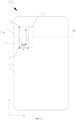
FIG. 3 is a top view of a side where a battery cover of a first electronic device is provided in implementations of the present disclosure. -
FIG. 4 is a schematic structural view illustrating an antenna assembly provided in other implementations of the present disclosure. -
FIG. 5 is a first schematic cross-sectional view of an electronic device illustrated inFIG. 3 along line A-A. -
FIG. 6 is a second schematic cross-sectional view of an electronic device illustrated inFIG. 3 along line A-A. -
FIG. 7 is a third schematic cross-sectional view of an electronic device illustrated inFIG. 3 along line A-A. -
FIG. 8 is a fourth schematic cross-sectional view of an electronic device illustrated inFIG. 3 along line A-A. -
FIG. 9 is a fifth schematic cross-sectional view of an electronic device illustrated inFIG. 3 along line A-A. -
FIG. 10 illustrates beam patterns of an antenna module provided in implementations of the disclosure, when disposed in free space and under a dielectric structure and at 28 gigahertz (GHz) and 28.5 GHz respectively. -
FIG. 11 is a top view of a side where a battery cover of a second electronic device is provided in other implementations of the present disclosure. -
FIG. 12 is a schematic cross-sectional view of an electronic device illustrated inFIG. 11 along line B-B. -
FIG. 13 is a top view of a side where a battery cover of a third electronic device is provided in other implementations of the present disclosure. -
FIG. 14 is a schematic cross-sectional view of an electronic device illustrated inFIG. 13 along line C-C. -
FIG. 15 is a top view of a side where a battery cover of a fourth electronic device is provided in other implementations of the present disclosure. -
FIG. 16 is a schematic cross-sectional view of an electronic device illustrated inFIG. 15 along line D-D. -
FIG. 17 is a top view of an electronic device provided in other implementations of the present disclosure. -
FIG. 18 is a side view of an electronic device provide in other implementations of the present disclosure. - The following will give a clear and complete description to technical solutions of the disclosure with combination of accompanying drawings in the implementations.
-
FIG. 1 is a schematic view illustrating an electronic device from a first view. Theelectronic device 100 may be any products with antenna, such as a tablet computer, a mobile phone, a notebook computer, an in-vehicle equipment, a wearable device, or the like. The present disclosure describes the mobile phone as an example of theelectronic device 100. For ease of description, theelectronic device 100 is defined with reference to a first viewing angle. Specifically, a width direction of theelectronic device 100 is defined as an X-axis direction, a length direction of theelectronic device 100 is defined as a Y-axis direction, and a thickness direction of theelectronic device 100 is defined as a Z-axis direction. -
FIG. 2 illustrates anantenna assembly 10 provided in implementations of the present disclosure. As illustrated inFIG. 2 , theantenna assembly 10 includes adielectric structure 1 and anantenna module 2. Thedielectric structure 1 has afirst region 11, asecond region 12, and athird region 13 connected in sequence. Theantenna module 2 faces thesecond region 12, theantenna module 2 is configured to receive and emit an electromagnetic wave signal. For ease of description, the electromagnetic wave signal received or emitted by theantenna module 2 is referred to as a radio frequency (RF) signal. In other words, theantenna module 2 is configured to receive and emit a RF signal. Thefirst region 11 is configured to bring a first phase variation to the RF signal, thesecond region 12 is configured to bring a second phase variation to the RF signal, thethird region 13 is configured to bring a third phase variation to the RF signal, and the second phase variation is different from the first phase variation and the third phase variation. - Different regions of the
dielectric structure 1 can bring different phase variations to the RF signal, such that a phase of the RF signal passing through thedielectric structure 1 is regulated, the RF signal emitted out of thedielectric structure 1 has the same or similar phase, thedielectric structure 1 can act as a "lens", which can converge the RF signal emitted by theantenna module 2 to concentrate energy of the RF signal, thereby increasing a gain of the RF signal emitted by theantenna module 2. - Specifically, the RF signal is a modulated electromagnetic wave with a certain radiation frequency. In this implementation, a transmission frequency band of the RF signal may include, but not limited to, millimeter-wave (mm-wave) frequency band, submillimeter frequency band, or terahertz frequency band. In other implementations, the transmission frequency band of the RF signal may include an electromagnetic wave in medium frequency band or low frequency band. Correspondingly, the
antenna module 2 can be any antenna capable of receiving and emitting the electromagnetic wave of mm-wave frequency band, submillimeter frequency band, terahertz frequency band, etc. Theantenna module 2 includes, but is not limited to, a phased array antenna, etc. In this implementation, the mm-wave signal is taken as an example of the RF signal for illustration. - Specifically, as illustrated in
FIG. 2 , thedielectric structure 1 as a whole is a substrate capable of making the RF signal pass through, such that the RF signal can be radiated out through thedielectric structure 1. The first phase variation brought by thefirst region 11 to the RF signal represents a difference value between a phase of the RF signal before reaching thefirst region 11 and a phase of the RF signal after passing through thefirst region 11. - In a process that the RF signal passes through the
dielectric structure 1, thedielectric structure 1 interacts with the RF signal, such that the RF signal has a varied phase after passing through thedielectric structure 1. Thefirst region 11 and thesecond region 12 of thedielectric structure 1 have different effects on the RF signal, therefore, thefirst region 11 and thesecond region 12 of thedielectric structure 1 bring different phase variations to the RF signal. As such, a RF signal after passing through thefirst region 11 has a phase the same as or substantially the same as a RF signal after passing through thesecond region 12, so as to concentrate the energy of the RF signal, and achieve beamforming of the RF signal. In this way, the gain of the RF signal can be increased with aid of thedielectric structure 1. - In terms of the material of the
dielectric structure 1, the material of thedielectric structure 1 may be locally uneven, such that thedielectric structure 1 can bring different phase variations to the RF signal. When thedielectric structure 1 is equivalent to a structure in which thefirst region 11 is made of an even material, thesecond region 12 is made of an even material, and thethird region 13 is made of an even material, thefirst region 11, thesecond region 12, and thethird region 13 each have a different equivalent dielectric constant. In this way, the RF signal may have different phase variations when interacting with thefirst region 11, thesecond region 12, and thethird region 13 respectively. Further, it is possible to make the RF signal after passing through thefirst region 11 have a phase the same as or substantially the same as the RF signal after passing through thesecond region 12. Thus the energy of the RF signal can be concentrated, and the beamforming of the RF signal can be achieved. In this way, the gain of the RF signal can be improved with aid of thedielectric structure 1. - In terms of the equivalent refractive index of the
dielectric structure 1, thedielectric structure 1 can act as a "lens" structure of the RF signal. Thefirst region 11, thesecond region 12, and thethird region 13 of thedielectric structure 1 each have a different equivalent refractive index to the RF signal. In this way, the RF signal may have different phase variations when interacting with thefirst region 11, thesecond region 12, and thethird region 13 respectively, and it is possible to make the RF signal after passing through the first region 11have a phase the same as or substantially the same as the RF signal after passing through thesecond region 12. Thus the energy of the RF signal can be concentrated, and the beamforming of the RF signal can be achieved. In this way, the gain of the RF signal can be improved with aid of thedielectric structure 1. - It can be understood that, the
first region 11, thesecond region 12, and thethird region 13 of thedielectric structure 1 can bring different phase variations to the RF signal due to reasons including, but not limited to, different characteristics of transmission materials, different secondary radiation waves generated, etc. - In this implementation, the manner that the second phase variation is set to be different from the first phase variation and the third phase variation includes, but is not limited to the following.
- In a first possible implementation, as illustrated in
FIG. 2 , the equivalent dielectric constant of thesecond region 12 is greater than that of thefirst region 11 and that of thethird region 13, such that the second phase variation is greater than the first phase variation and the third phase variation. In other words, the equivalent refractive index of thesecond region 12 is less than that of thefirst region 11 and that of thethird region 13, such that thefirst region 11, thesecond region 12, and thethird region 13 of thedielectric structure 1 is equivalent to a "lens" structure of the RF signal with a large thickness in the middle and a small thickness on both ends. - When the
antenna module 2 faces thesecond region 12, a distance between theantenna module 2 and thesecond region 12 is less than a distance between theantenna module 2 and thefirst region 11, and also less than a distance between theantenna module 2 and thethird region 13, such that a RF signal reaching a surface of thesecond region 12 from theantenna module 2 has a phase less than a RF signal reaching a surface of thefirst region 11 from theantenna module 2, and also less than a RF signal reaching a surface of thethird region 13 from theantenna module 2. - When the second phase variation is greater than the first phase variation and the third phase variation, the
second region 12 brings a greater phase compensation to the RF signal than thefirst region 11 and thethird region 13, such that the RF signal has the same or substantially the same phases after passing through thefirst region 11, thesecond region 12, and thethird region 13. In this way, the energy of the RF signal can be concentrated, and the beamforming of the RF signal can be achieved, such that the gain of the RF signal emitted by theantenna module 2 can be increased after the RF signal passes through thedielectric structure 1. - Furthermore, as illustrated in
FIG. 2 , the equivalent dielectric constant of thefirst region 11 can be the same as that of thethird region 13, such that the first phase variation is the same as the third phase variation. In other words, the equivalent refractive index of thefirst region 11 can be the same as that of thethird region 13, such that thefirst region 11, thesecond region 12, and thethird region 13 of thedielectric structure 1 is equivalent to a symmetrical "lens" structure which has a large thickness in the middle and a small thickness on both ends. - The first phase variation can be the same as the third phase variation, such that the RF signal after passing through the
first region 11 and the RF signal after passing through thethird region 13 can be symmetrically concentrated toward thesecond region 12. Furthermore, a main lobe direction of the RF signal after passing through thefirst region 11 and the RF signal after passing through thethird region 13 can be along or approximately along a normal direction of thesecond region 12. The main lobe refers to a beam with the greatest radiation intensity in the RF signal. - In other implementations, the equivalent dielectric constant of the
first region 11 is different from thethird region 13, such that the first phase variation is different from the third phase variation. In this way, thedielectric structure 1 can bring a phase variation to the RF signal more flexibly, and energy concentration as well as the main lobe direction of the RF signal after passing through thefirst region 11 and the RF signal after passing thethird region 13 can be more flexible, so as to adapt to different designs of theantenna assembly 10. - In a second possible implementation, by setting the equivalent dielectric constant of the
second region 12 to be less than that of thefirst region 11 and thethird region 13, the second phase variation is less than the first phase variation and the third phase variation. In other words, by adjusting the equivalent refractive index of thesecond region 12 to be greater than that of thefirst region 11 and thethird region 13, thefirst region 11, thesecond region 12, and thethird region 13 of thedielectric structure 1 is equivalent to a "lens" structure which has a small thickness in the middle and a large thickness on both ends. - In this implementation, the first phase variation can be the same as or different from the third phase variation, which will not be repeated herein.
- The second phase variation can be less than the first phase variation and the third phase variation, such that the
second region 12 brings a less phase compensation to the RF signal than thefirst region 11 and thethird region 13. In this way, the RF signal radiated has a wider spatial coverage and a larger spatial coverage angle. - In other implementations, the
dielectric structure 1 further includes a fourth region disposed at thefirst region 11 away from thesecond region 12 and a fifth region disposed at thethird region 13 away from thesecond region 12. A phase variation brought by each of the fourth region and the fifth region to the RF signal is different from that brought by each of thefirst region 11 and thesecond region 12. Furthermore, the phase variation brought by the fourth region to the RF signal is the same as that brought by the fifth region to the RF signal, and the phase variation brought by each of the fourth region and the fifth region to the RF signal is less than that brought by thefirst region 11 to the RF signal, such that thedielectric structure 1 can bring gradient phase variations to the RF signal in different regions. Thedielectric structure 1 provided in this implementation, is equivalent to a "lens" which has a large thickness in the middle and gradually reduced thickness on both ends, such that radiation of the RF signal emitted by theantenna module 2 is closer to the normal direction of thesecond region 12, which increases the gain of the RF signal emitted byantenna module 2. - As illustrated in
FIG. 2 , thesecond region 12 has a transmittance to the RF signal greater than thefirst region 11 and thethird region 13. - Specifically, the
second region 12 is provided with a metamaterial structure, the metamaterial structure can be thought of as molecules and atoms of materials, and the metamaterial structure consists of element structures with a size much smaller than a wavelength. According to the equivalent-medium theory, an artificial specific electromagnetic medium with a certain number of element structures which are arranged at regular intervals as a whole can be equivalent to a homogeneous medium with certain equivalent electromagnetic parameters. Suppose that the metamaterial structure is an equivalent homogeneous medium with certain thickness and has reflection and transmission coefficients, by adjusting the metamaterial structure, the reflection coefficient can be minimized and the transmission coefficient can be maximized. For example, by adjusting the metamaterial structure, the transmission coefficient of the metamaterial structure to the RF signal can be adjusted to be the same as or substantially the same as the transmission coefficient of air to the RF signal, such that the metamaterial structure has a relatively high transmittance to RF signal. - The
second region 12 is provided with the metamaterial structure, such that thesecond region 12 has a second transmittance to the RF signal. Thefirst region 11 has a first transmittance to the RF signal and thethird region 13 has a third transmittance to the RF signal. Because thesecond region 12 is provided with the metamaterial structure, the second transmittance is greater than the first transmittance and the second transmittance. When theantenna module 2 faces thesecond region 12, more RF signals of theantenna module 2 can pass through thesecond region 12, which is possible to reduce the RF signal loss of theantenna module 2 caused by thedielectric structure 1, and improve radiation efficiency of theantenna module 2. When theantenna module 2 is applied to theelectronic device 100 such as a mobile phone and the RF signal is in the mm-wave frequency band, application and radiation effect of the mm-wave frequency band in theelectronic devices 100 such as a mobile phone can be improved. - For example, as illustrated in
FIG. 3 , theelectronic device 100 is a mobile phone. Thedielectric structure 1 is a battery cover of theelectronic device 100. Theantenna module 2 is disposed in theelectronic device 100. Theantenna module 2 receives and emits the RF signal toward the battery cover to realize communication of theelectronic device 100. The RF signal can be a mm-wave signal. In this implementation, the battery cover of theelectronic device 100 is improved by disposing the metamaterial structure at a partial region of the battery cover. A region of the battery cover where the metamaterial structure is disposed serves as thesecond region 12, and regions of the battery cover on two opposite ends of the metamaterial serve as thefirst region 11 and thethird region 13. The metamaterial structure includes, but is not limited to, a one-dimensional, two-dimensional or three-dimensional conductive layer structure. On one hand, with aid of the metamaterial structure, the battery cover can exhibit a high radio-wave transmission characteristic to the mm-wave frequency band, and can act as a "mm-wave transparent battery cover" which has a minimum coverage effect (blocking signal radiation) on the mm-wave antenna module 2. On the other hand, the battery cover can act as a local "lens" to achieve the beamforming of the mm-wave frequency band signal, and increase the gain of the mm-wave antenna module 2. With the above design, it is possible to optimize application of mm-wave frequency band in theelectronic device 100 such as the mobile phone and the like, and improve a communication rate and a frequency band of signals inelectronic devices 100. - As illustrated in
FIG. 2 andFIG. 3 , the orthographic projection ofantenna module 2 on thedielectric structure 1 falls in thesecond region 12. - Specifically, as illustrated in
FIG. 2 andFIG. 3 , thesecond region 12 is at a back surface of theelectronic device 100. Thesecond region 12 has a size of W1 in the X-axis direction and a size of L1 in the Y-axis direction, and theantenna module 2 has a size of W2 in the X-axis direction and a size of L2 in the Y-axis direction, where W1 ≥ W2 , and L 1 ≥ L 2. Because thesecond region 12 has a relatively great transmittance to the RF signal, by setting size of theantenna module 2 to be less than that of thesecond region 12, more RF signals emitted from theantenna module 2 passes through thesecond region 12, such that the loss of the RF signals can be reduced, and the radiation efficiency of theantenna module 2 can be improved. - As illustrated in
FIG. 2 , a center of theantenna module 2 is aligned with a center of thesecond region 12 in an arrangement direction of thefirst region 11, thesecond region 12, and thethird region 13. - Specifically, the
antenna module 2 functions as a point emission source. By aligning the center of theantenna module 2 with the center of thesecond region 12, the center of theantenna module 2 is in the normal direction of thesecond region 12, such that after a RF signal radiated by theantenna module 2 passes through thefirst region 11, thesecond region 12, and thethird region 13, the spherically radiated RF signal can form a plane beam along the normal direction of thesecond region 12, so as to achieve the beamforming of the RF signal, increase the gain of the RF signal, and optimize performance of theantenna module 2 in free space. - Improvements to the
second region 12 include, but are not limited to, improvements to materials of thesecond region 12, or provision of the metamaterial structure on thesecond region 12, such that the phase variation to the RF signal brought by thesecond region 12 can be greater than that brought by thefirst region 11 and thethird region 13, the gain of the RF signal of theantenna module 2 can be increased with aid of thedielectric structure 1, and application of theantenna assembly 10 in theelectronic device 100 such as a mobile phone can be improved. The improvements to thesecond region 12 in the present disclosure include, but are not limited to those provided in the implementation below. - As illustrated in
FIG. 4 , thedielectric structure 1 includes ahousing substrate 14 and aresonant structure 15 disposed at thehousing substrate 14. A region of thehousing substrate 14 where theresonant structure 15 is disposed serves as thesecond region 12, a region of thehousing substrate 14 at one side of theresonant structure 15 serves as thefirst region 11, and a region of thehousing substrate 14 at the other side of theresonant structure 15 serves as thethird region 13. - Specifically, the
electronic device 100 is a mobile phone, for example. Thedielectric structure 1 may be a battery cover of the mobile phone. Theresonant structure 15 is configured to generate a secondary radiation wave under the action of the RF signal, the secondary radiation wave interacts with an incident RF signal to change the phase of the RF signal, such that thesecond region 12 of thedielectric structure 1 can bring a relatively great phase variation to the RF signal. Thehousing substrate 14 is part of a housing of theelectronic device 100, and thehousing substrate 14 itself can change the phase of the RF signal due to material loss, surface waves and other effects. The phase variation of thehousing substrate 14 to the RF signal is less than the phase variation brought by a housing substrate provided with theresonant structure 15 to the RF signal. - In this implementation, by disposing the
resonant structure 15 at a partial region of thehousing substrate 14, thehousing substrate 14 itself brings a less phase variation to the RF signal, such that thedielectric structure 1 can be formed into a structure which can bring a less phase variation, a great phase variation, and a less phase variation in different regions of thedielectric structure 1. Such structure of thedielectric structure 1 is similar to a "lens" which has a large thickness in the middle and a small thickness on both sides, so as to achieve beamforming of the RF signal of theantenna module 2, increase a gain of theantenna module 2, and further achieve a wider application of the mm-wave frequency band in theelectronic device 100 such as a mobile phone. - The
resonant structure 15 can be disposed at a partial region of thehousing substrate 14 in various manners which are not limited herein and can include, but are not limited to, the manners provided in the following implementations. - In a first possible implementation, as illustrated in
FIG.5 , thehousing substrate 14 has afirst surface 141 and asecond surface 142 which is opposite to thefirst surface 141 and faces theantenna module 2. Theresonant structure 15 is disposed on thefirst surface 141. - Specifically, as illustrated in
FIG. 5 , thehousing substrate 14 is the battery cover of theelectronic device 100, for example. Thefirst surface 141 is an outer surface of thehousing substrate 14, and thesecond surface 142 is an inner surface of thehousing substrate 14. When theresonant structure 15 is disposed on thefirst surface 141, theresonant structure 15 may be disposed on a flexible substrate, and the flexible substrate is fixed on thefirst surface 141, such that theresonant structure 15 is fixed on thehousing substrate 14. It can be understood that, in this implementation, theresonant structure 15 is disposed outside thehousing substrate 14, and theantenna module 2 is disposed inside theelectronic device 100 and faces theresonant structure 15. Theresonant structure 15 will not occupy space in theelectronic device 100. In addition, when theresonant structure 15 and theantenna module 2 need to be disposed by a certain distance, theresonant structure 15 can be disposed outside thehousing substrate 14. As such, a distance between theantenna module 2 and the inner surface of thehousing substrate 14 will not be too large, and the thickness of theelectronic device 100 can be further reduced. It can be understood that, a surface of theresonant structure 15 can be processed to have a consistent appearance with thefirst surface 141. - In a second possible implementation, as illustrated in
FIG. 6 , theresonant structure 15 is disposed on thesecond surface 142, which is different from the first possible implementation. - The
resonant structure 15 is disposed inside thehousing substrate 14 of theelectronic device 100 when theresonant structure 15 is disposed on thesecond surface 142. As such, theresonant structure 15 is not vulnerable to wear or damage, service life of theantenna assembly 10 can be prolonged, and the appearance consistency of thehousing substrate 14 can also be ensured. - In a third possible implementation, as illustrated in
FIG. 7 , theresonant structure 15 is at least partially embedded between thefirst surface 141 and thesecond surface 142, which is different from the first possible implementation. - Specifically, as illustrated in
FIG. 7 , thefirst surface 141 or thesecond surface 142 can define agroove 143, and theresonant structure 15 can be disposed in thegroove 143. - The
resonant structure 15 is at least partially embedded between thefirst surface 141 and thesecond surface 142, such that thickness of theresonant structure 15 partially coincides with thickness of thehousing substrate 14, and the thickness of theelectronic device 100 is reduced. In this case, thegroove 143 is a positioning structure for theresonant structure 15, so as to improve assembly efficiency of theantenna assembly 10. - Furthermore, as illustrated in
FIG. 8 , theresonant structure 15 as a whole can be embedded between thefirst surface 141 and thesecond surface 142. Theresonant structure 15 can be integrally formed with thehousing substrate 14, such that the thickness of theelectronic device 100 can be reduced by avoiding that theresonant structure 15 is stacked with thehousing substrate 14 in the Z-axis direction. - In a fourth possible implementation, as illustrated in
FIG. 9 , thehousing substrate 14 may define a throughhole 143 extending through thefirst surface 141 and thesecond surface 142, which is different from the first possible implementation. Theresonant structure 15 is received in the throughhole 143, such that the thickness of theelectronic device 100 can be reduced by avoiding that theresonant structure 15 is stacked with thehousing substrate 14 in the Z-axis direction. - As illustrated in
FIG. 2 , theantenna module 2 is separated from theresonant structure 15 by a predetermined distance, such that a relatively strong RF signal emitted by theantenna module 2 can be adequately emitted to each region of theresonant structure 15, and a utilization rate of theresonant structure 15 can be improved. - Specifically, the
first region 11, thesecond region 12, and thethird region 13 are arranged along a predetermined direction, and the predetermined distance increases as a size of theresonant structure 15 in the predetermined direction increases, such that the relatively strong RF signal emitted by theantenna module 2 can be adequately emitted to each region of theresonant structure 15, and the utilization rate of theresonant structure 15 can be improved. - Specifically, the predetermined distance satisfies a formula (1)

resonant structure 15 in the predetermined direction, ϕ 1 represents the second phase variation, ϕ 2 represents the first phase variation, and λ represents a wavelength of the RF signal. - It can be understood that, the predetermined distance is relative to a difference between the first phase variation and the second phase variation, and also relative to the wavelength of the RF signal, in other words, the distance is relative to frequency of the RF signal. In addition, the predetermined distance is also relative to a length of the
resonant structure 15 in the predetermined direction. - The above formula (1) for determining the predetermined distance is provided in this implementation. By calculating the predetermined distance with the above formula (1), the predetermined distance, with which an optimal gain effect on the RF signal can be achieved, can be reasonably designed. As illustrated in
FIG. 10 , when the above formula (1) is satisfied, compared with in the free space, when theantenna module 2 is under the "lens" (metasurface lens) with theresonant structure 15 and the RF signal is at a frequency point of 28 gigahertz (GHz), the gain of theantenna module 2 is increased by 0.8dB; when the RF signal is at a frequency point of 28.5GHz, the gain of theantenna module 2 is increased by 1.3db. In other words, theantenna assembly 10 provided in the present disclosure can improve the gain of the RF signal in the mm-wave frequency band. - As illustrated in
FIG. 11 , theresonant structure 15 includes multipleresonant elements 16 arranged in an array and insulated from one another, and each of the multipleresonant elements 16 includes at least one conductive-patch layer 161(i.e., layer of a conductive-patch). - As illustrated in
FIG. 11 andFIG. 12 , when the at least one conductive-patch layer 161 is a single conductive-patch layer 161, theresonant structure 15 includes one conductive layer in which multiple throughholes 143 are defined and arranged at regular intervals. Each of the multiple throughholes 143 has various shapes including, but not limited to, cross, rectangle, rectangular ring, cross ring, circle ring, triangle, circle, polygon, etc. The throughhole 143 is equivalent to a capacitor of theresonant structure 15, and a conductive part between two adjacent throughholes 143 is equivalent to an inductor of theresonant structure 15. Theresonant structure 15 has full transparent characteristics to the incident RF signal at a resonant frequency point, and has reflection characteristics of different degrees to the incident RF signal at other frequency points. When the frequency band of the RF signal is a resonant frequency band, the RF signal radiated into theresonant structure 15 can excite theresonant structure 15 to generate a secondary radiation, such that theresonant structure 15 has relatively high transmittance performance for the RF signal. - In addition, the multiple through
holes 143 in theresonant structure 15 may also be arranged at irregular intervals. The multiple throughholes 143 in theresonant structure 15 may have a same shape or different shapes. - As illustrated in
FIG. 13 andFIG. 14 , when the at least one conductive-patch layer 161 has multiple conductive-patch layers spaced apart, theresonant structure 15 includes multiple conductive layers spaced apart, each of the multiple conductive layers may includeconductive patches 161 which are arranged in an array, andconductive patches 161 of different conductive layers have a same shape or different shapes. - Specifically, the
resonant structure 15 includes the multiple conductive layers spaced apart, and each of the multiple conductive layers may be a patch-type structure element or an aperture-type structure element (i.e., grid-type structure). Specifically, the patch-type structure element includes the multipleconductive patches 161 which are arranged in an array and insulated from one another. Each of the multipleconductive patches 161 has various shapes including, but not limited to, cross, rectangle, rectangular ring, cross ring, circle ring, triangle, circle, polygon, etc. Theconductive patch 161 is equivalent to an inductor of theresonant structure 15, and a gap between two adjacentconductive patches 161 is equivalent to a capacitor of theresonant structure 15. The multipleconductive patches 161 have full reflection characteristics to the incident RF signal at a resonant frequency point, and have transmittance characteristics of different degrees to the incident RF signal at other frequency points. The grid-type structure element includes the conductive layer and the multiple throughholes 143 defined in the conductive layer and arranged at regular intervals. Each of the multiple throughholes 143 has various shapes including, but not limited to cross, rectangle, rectangular ring, cross ring, circle ring, triangle, circle, polygon, etc. - Specifically, the multiple
conductive patches 161 on each of the multiple conductive layers may have a same shape or different shapes, and adjacent conductive layers may be in a same type or different types. For example, when the multiple conductive layers are two conductive layers, the two conductive layers may adopt the patch-type structure element and the aperture-type structure element, the patch-type structure element and the patch-type structure element, the aperture-type structure element and the aperture-type structure element, or the aperture-type structure element and the patch-type structure element. - The reflection brought by the
dielectric structure 1 to the RF signal can be reduced when theresonant structure 15 is disposed at thehousing substrate 14, such that thedielectric structure 1 can have an improved transmittance to the RF signal. When theantenna assembly 10 is applied to a mobile phone, the battery cover can have an improved transmittance to the RF signal. Since theresonant structure 15 is disposed at a partial region of thehousing substrate 14, such that thehousing substrate 14 together with theresonant structure 15 can act as a "lens", the energy of the RF signal can be concentrated, and the gain of theantenna module 2 can be enhanced. - It can be understood that, the multiple
conductive patches 161 are made of metal materials. In other implementations, the multipleconductive patches 161 may also be made of non-metallic conductive materials. - The
housing substrate 14 may be made of at least one or a combination of plastic, glass, sapphire, and ceramic. - As illustrated in
FIG. 15 , theantenna module 2 includes multiple radiatingelements 21. An arrangement direction of themultiple radiating elements 21 intersects an arrangement direction of thefirst region 11, thesecond region 12, and thethird region 13. - In this implementation, the
multiple radiating elements 21 are arranged in a linear array. In other implementations, themultiple radiating elements 21 may also be arranged in a two-dimensional matrix or a three-dimensional matrix. - As illustrated in
FIG. 16 , theantenna module 2 further includes aRF chip 22 and aninsulated substrate 23. Themultiple radiating elements 21 are disposed on theinsulated substrate 23, and on a side of theinsulated substrate 23 facing a housing assembly. TheRF chip 22 is configured to generate an excitation signal (also referred to the RF signal). TheRF chip 22 may be disposed on a main board 20 of theelectronic device 100, where theRF chip 22 is at a side of theinsulated substrate 23 away from themultiple radiating elements 21. TheRF chip 22 is electrically connected with themultiple radiating elements 21 through transmission lines embedded in theinsulated substrate 23. - Furthermore, as illustrated in
FIG. 16 , each of themultiple radiating elements 21 includes at least onefeed point 24, eachfeed point 24 is electrically connected with theRF chip 22 through a transmission line, a distance between eachfeed point 24 and a center of a radiatingelement 21 corresponding to thatfeed point 24 is greater than a predetermined distance. Input impedance of themultiple radiating elements 21 can be changed by adjusting a location of thefeed point 24. In this implementation, by setting the distance between eachfeed point 24 and the center of the radiatingelement 21 corresponding to thatfeed point 24 to be greater than the predetermined distance, the input impedance of themultiple radiating elements 21 is adjusted. By adjusting the input impedance of themultiple radiating elements 21, the input impedance of themultiple radiating elements 21 can be matched with output impedance of theRF chip 22. When the input impedance of themultiple radiating elements 21 is matched with the output impedance of theRF chip 22, the excitation signal generated by theRF chip 22 has a minimum reflection amount. - It can be understood that, the
antenna module 2 may be at least one or a combination of a patch antenna, a laminated antenna, a dipole antenna, a magneto-electric dipole antenna, and a quasi-Yagi antenna. - It can be understood that, the
electronic device 100 provided in the first implementation of the present disclosure includes theantenna assembly 10 according to any of the above implementations. When theelectronic device 100 is a mobile phone, thedielectric structure 1 of theantenna assembly 10 may be a housing structure, which includes thehousing substrate 14 and theresonant structure 15 disposed on thehousing substrate 14. - In a second implementation, an
electronic device 100 is further provided. Theelectronic device 100 in the second implementation is substantially identical to theelectronic device 100 in the first implementation except the following. Theelectronic device 100 includes a housing, at least oneresonant structure 15 disposed at a partial region of the housing, and at least one mm-wave antenna array. Each mm-wave antenna array faces oneresonant structure 15. Theresonant structure 15 is configured to bring a first phase variation to a RF signal radiated by the mm-wave antenna array. The housing is configured to bring a second phase variation to the RF signal emitted by the mm-wave antenna array at a region without theresonant structure 15. The first phase variation is greater than the second phase variation, such that theresonant structure 15 enhances a gain of the RF signal emitted by the mm-wave antenna array. - As for the housing, reference can be made to the above description of the
housing substrate 14 in the first implementation. As for theresonant structure 15, reference can be made to the above description in the first implementation. As for the mm-wave antenna array, reference can be made to the above description of theantenna module 2 in the first implementation, which will not be repeated herein. - In this implementation, a mobile phone is taken as an example of the
electronic device 100 for illustration. The housing is the battery cover. Theelectronic device 100 at least includes a mobile phone capable of communication with a mm-wave. - The
resonant structure 15 is disposed at a partial region of the housing, such that the phase variation of the RF signal in the partial region is greater than that in other regions of the housing, the phases of the RF signal passing through the housing are regulated, and the RF signal emitted from the housing has the same phase. Therefore, the energy of the RF signal emitted by the mm-wave antenna array can be concentrated, the gain of the RF signal emitted by the mm-wave antenna array can be increased, and communication quality of theelectronic device 100 can be improved. - As illustrated in
FIG. 17 , the housing includes thebattery cover 143. The at least oneresonant structure 15 includes a first resonant structure 151 and a secondresonant structure 152 which are disposed on thebattery cover 143. The at least one mm-wave antenna array includes a first mm-wave antenna array 25 facing the first resonant structure 151 and a second mm-wave antenna array 26 facing the secondresonant structure 152. An arrangement direction of multiple radiatingelements 21 in the first mm-wave antenna array 25 intersects an arrangement direction of multiple radiatingelements 21 in the second mm-wave antenna array 26. - Specifically,
multiple radiation elements 21 in the first mm-wave antenna array 25 are arranged in the Y-axis direction, the first mm-wave antenna array 25 performs beam scanning in the Y-axis direction, and a gain of the first mm-wave antenna array 25 in the Y-axis direction is enhanced.Multiple radiating elements 21 in the second mm-wave antenna array 26 are arranged in the X-axis direction, the second mm-wave antenna array 26 performs the beam scanning in the X-axis direction, and a gain of the second mm-wave antenna array 26 in the X-axis direction is enhanced, such that the first mm-wave antenna array 25 and the second mm-wave antenna array 26 perform the beam scanning with high gain in different directions respectively, so as to improve beam space coverage of theelectronic device 100 and a gain of theelectronic device 100. - Specifically, as illustrated in
FIG. 18 , the housing includes aframe 144 surrounding a peripheral side of thebattery cover 143, and the at least oneresonant structure 15 further includes a thirdresonant structure 153 disposed on theframe 144. The at least one mm-wave antenna array further includes a third mm-wave antenna array 27 facing the thirdresonant structure 153. An arrangement direction of themultiple radiating elements 21 in the third mm-wave antenna array 27 is consistent with an extension direction of a side edge of theframe 144 where the thirdresonant structure 153 is disposed. - Specifically, the arrangement direction of the
multiple radiating elements 21 in the third mm-wave antenna array 27 extends along the extension direction of the side edge of the 144, such as along the Y-axis direction or the X-axis direction. The third mm-wave antenna array 27 performs beam scanning in the Y-axis direction, and a gain of the third mm-wave antenna array 27 in the Y-axis direction is enhanced. In combination with the first mm-wave antenna array 25 and the second mm-wave antenna array 26, theelectronic device 100 provided in this implementation can perform the beam scanning with high gain in vertical and horizontal directions on the back surface of theelectronic device 100, and can also perform the beam scanning with high gain on four sides of theelectronic device 100, so as to improve the beam space coverage of theelectronic device 100 and the gain of theelectronic device 100. - The present disclosure includes, but is not limited to, the above three antenna arrays and arrangement of the three antenna arrays.
- The above are part of implementations in the present disclosure. It should be noted that, for those of ordinary skill in the art, without departing from principles of the present disclosure, several improvements and modifications can be made, and these improvements and modifications are also repeated as a scope of protection in the present disclosure.
Claims (20)
- An antenna assembly, comprising:a dielectric structure having a first region, a second region, and a third region connected in sequence;an antenna module, facing the second region and configured to emit a radio frequency (RF) signal, wherein the first region is configured to bring a first phase variation to the RF signal, the second region is configured to bring a second phase variation to the RF signal, the third region is configured to bring a third phase variation to the RF signal, and the second phase variation is different from the first phase variation and the third phase variation.
- The antenna assembly of claim 1, wherein the second phase variation is greater than the first phase variation and the third phase variation, such that a gain of the RF signal emitted by the antenna module is enhanced after the RF signal passes through the dielectric structure.
- The antenna assembly of claim 1, wherein the second phase variation is less than the first phase variation and the third phase variation, such that a coverage of the RF signal emitted by the antenna module is enhanced after the RF signal passes through the dielectric structure.
- The antenna assembly of claim 1, wherein the first phase variation is equal to the third phase variation.
- The antenna assembly of claim 1, wherein the second region has a transmittance to the RF signal greater than the first region and the third region.
- The antenna assembly of claim 1, wherein an orthographic projection of the antenna module on the dielectric structure falls within the second region.
- The antenna assembly of any of claims 1 to 6, wherein the dielectric structure comprises a housing substrate and a resonant structure disposed at the housing substrate, a region of the housing substrate where the resonant structure is disposed serves as the second region, a region of the housing substrate disposed at one side of the resonant structure serves as the first region, and a region of the housing substrate disposed at the other side of the resonant structure serves as the third
- The antenna assembly of claim 7, wherein the housing substrate has a first surface and a second surface which is opposite to the first surface and faces the antenna module, wherein one of:the resonant structure is disposed on the first surface;the resonant structure is disposed on the second surface; orthe resonant structure is at least partially embedded between the first surface and the second surface.
- The antenna assembly of claim 7, wherein the housing substrate defines a through hole, and the resonant structure is embedded in the through hole.
- The antenna assembly of claim 7, wherein the antenna module is spaced apart from the resonant structure by a predetermined distance.
- The antenna assembly of claim 10, wherein the first region, the second region, and the third region are arranged along a predetermined direction, and the predetermined distance increases as a size of the resonant structure in the predetermined direction increases.
- The antenna assembly of claim 10, wherein the predetermined distance satisfies:

- The antenna assembly of claim 7, wherein the resonant structure comprises a plurality of resonant elements arranged in an array, and each of the plurality of resonant elements comprises at least one conductive-patch layer.
- The antenna assembly of claim 13, wherein the at least one conductive-patch layer is a single conductive-patch layer, and the resonant structure comprises one conductive layer in which a plurality of through holes are defined and arranged at regular intervals.
- The antenna assembly of claim 13, wherein the at least one conductive-patch layer is a plurality of conductive-patch layers spaced apart from one another, the resonant structure comprises a plurality of conductive layers spaced apart from one another, each of the plurality of conductive layers comprises conductive patches arranged in an array, and conductive patches of different conductive layers have a same shape or different shapes.
- The antenna assembly of claim 1, wherein the antenna module further comprises:
a plurality of radiating elements, wherein an arrangement direction of the plurality of radiating elements intersects an arrangement direction of the first region, the second region, and the third region. - An electronic device, comprising the antenna assembly of any of claims of 1 to 16.
- An electronic device, comprising:a housing;at least one resonant structure disposed at a partial region of the housing; andat least one millimeter-wave (mm-wave) antenna array, wherein each of the at least one mm-wave antenna array faces one resonant structure, the resonant structure is configured to bring a first phase variation to a mm-wave emitted by the mm-wave antenna array, a region of the housing without the resonant structure is configured to bring a second phase variation to the mm-wave emitted by the mm-wave antenna array, the first phase variation is greater than the second phase variation, such that the resonant structure enhances a gain of the mm-wave emitted by the mm-wave antenna array.
- The electronic device of claim 18, wherein the housing comprises a battery cover, the at least one resonant structure comprises a first resonant structure and a second resonant structure which are disposed on the battery cover, the at least one mm-wave antenna array comprises a first mm-wave antenna array facing the first resonant structure and a second mm-wave antenna array facing the second resonant structure, and an arrangement direction of radiating elements in the first mm-wave antenna array intersects an arrangement direction of radiating elements in the second mm-wave antenna array.
- The electronic device of claim 19, wherein the housing comprises a frame surrounding a peripheral side of the battery cover, the at least one resonant structure further comprises a third resonant structure disposed on the frame, the at least one mm-wave antenna array further comprises a third mm-wave antenna array facing the third resonant structure, an arrangement direction of radiating elements in the third mm-wave antenna array is consistent with an extension direction of a side edge of the frame where the third resonant structure is disposed.
Applications Claiming Priority (2)
| Application Number | Priority Date | Filing Date | Title |
|---|---|---|---|
| CN201910588862.3A CN112234341B (en) | 2019-06-30 | 2019-06-30 | Antenna assembly and electronic equipment |
| PCT/CN2020/098115 WO2021000780A1 (en) | 2019-06-30 | 2020-06-24 | Antenna assembly and electronic device |
Publications (3)
| Publication Number | Publication Date |
|---|---|
| EP3972050A1 true EP3972050A1 (en) | 2022-03-23 |
| EP3972050A4 EP3972050A4 (en) | 2022-08-03 |
| EP3972050B1 EP3972050B1 (en) | 2025-10-29 |
Family
ID=74100618
Family Applications (1)
| Application Number | Title | Priority Date | Filing Date |
|---|---|---|---|
| EP20834706.2A Active EP3972050B1 (en) | 2019-06-30 | 2020-06-24 | Antenna assembly and electronic device |
Country Status (4)
| Country | Link |
|---|---|
| US (1) | US20220102841A1 (en) |
| EP (1) | EP3972050B1 (en) |
| CN (1) | CN112234341B (en) |
| WO (1) | WO2021000780A1 (en) |
Families Citing this family (5)
| Publication number | Priority date | Publication date | Assignee | Title |
|---|---|---|---|---|
| CN112821050B (en) * | 2021-01-07 | 2023-04-25 | Oppo广东移动通信有限公司 | Antenna components and electronics |
| CN112928493B (en) * | 2021-01-28 | 2025-01-03 | Oppo广东移动通信有限公司 | Electronic devices |
| CN115701672A (en) * | 2021-08-02 | 2023-02-10 | 苏州硕贝德创新技术研究有限公司 | Combined antenna and terminal with millimeter wave radio frequency module loaded with metamaterial structure |
| CN118508074B (en) * | 2023-02-15 | 2025-10-31 | 华为技术有限公司 | Electronic equipment |
| WO2026015440A1 (en) * | 2024-07-08 | 2026-01-15 | Amphenol Antenna Solutions, Inc. | Multi-beam 3-dimensional metasurface lens for high capacity sites |
Family Cites Families (21)
| Publication number | Priority date | Publication date | Assignee | Title |
|---|---|---|---|---|
| JP3786497B2 (en) * | 1997-06-13 | 2006-06-14 | 富士通株式会社 | Semiconductor module with built-in antenna element |
| US6072441A (en) * | 1997-11-06 | 2000-06-06 | Nec Corporation | Method of producing a helical antenna and the helical antenna apparatus |
| JP3284971B2 (en) * | 1998-05-28 | 2002-05-27 | 防衛庁技術研究本部長 | Planar antenna |
| CN102800974B (en) * | 2011-06-21 | 2014-11-26 | 深圳光启高等理工研究院 | A base station antenna |
| CN103094712B (en) * | 2011-10-31 | 2017-02-01 | 深圳光启高等理工研究院 | Lens antenna based on metamaterial |
| CN102916258A (en) * | 2012-09-20 | 2013-02-06 | 日月光半导体制造股份有限公司 | Antenna module and method for manufacturing the same |
| JP5941854B2 (en) * | 2013-02-13 | 2016-06-29 | 日立オートモティブシステムズ株式会社 | Millimeter-wave dielectric lens antenna and speed sensor using the same |
| CN104377452B (en) * | 2014-11-06 | 2017-05-24 | 南京邮电大学 | Design method for pure medium electromagnetic lens based on meta-surface |
| CN204927532U (en) * | 2015-09-07 | 2015-12-30 | 常州第四无线电厂有限公司 | High Gain Dielectric Lens Horn Antenna Receiver |
| KR102482836B1 (en) * | 2016-01-07 | 2022-12-29 | 삼성전자주식회사 | Electronic device with antenna device |
| US10103424B2 (en) * | 2016-04-26 | 2018-10-16 | Apple Inc. | Electronic device with millimeter wave yagi antennas |
| CN106486734B (en) * | 2016-11-03 | 2019-02-26 | 合肥工业大学 | Antenna system with gain self-correction function |
| US10879592B2 (en) * | 2016-11-25 | 2020-12-29 | Sony Mobile Communications Inc. | Vertical antenna patch in cavity region |
| KR102394127B1 (en) * | 2017-02-21 | 2022-05-04 | 삼성전자 주식회사 | Apparatus comprising planar lens antenna and method for controling the same |
| US10211532B2 (en) * | 2017-05-01 | 2019-02-19 | Huawei Technologies Co., Ltd. | Liquid-crystal reconfigurable multi-beam phased array |
| KR102491506B1 (en) * | 2017-11-28 | 2023-01-25 | 삼성전자주식회사 | An electronic device comprising antenna |
| CN108110419A (en) * | 2017-12-14 | 2018-06-01 | 中国科学院长春光学精密机械与物理研究所 | A kind of method for correcting radome boresight error |
| CN108777359A (en) * | 2018-05-24 | 2018-11-09 | 西安电子科技大学 | Metamaterial antenna cover based on frequency trigger mechanism |
| CN208385608U (en) * | 2018-07-20 | 2019-01-15 | Oppo广东移动通信有限公司 | Electronic equipment |
| CN109088180B (en) * | 2018-08-12 | 2020-11-20 | 瑞声科技(南京)有限公司 | AOG antenna system and mobile terminal |
| CN112103662B (en) * | 2019-06-17 | 2022-03-01 | Oppo广东移动通信有限公司 | Lens antenna module and electronic equipment |
-
2019
- 2019-06-30 CN CN201910588862.3A patent/CN112234341B/en not_active Expired - Fee Related
-
2020
- 2020-06-24 EP EP20834706.2A patent/EP3972050B1/en active Active
- 2020-06-24 WO PCT/CN2020/098115 patent/WO2021000780A1/en not_active Ceased
-
2021
- 2021-12-08 US US17/643,365 patent/US20220102841A1/en not_active Abandoned
Also Published As
| Publication number | Publication date |
|---|---|
| WO2021000780A1 (en) | 2021-01-07 |
| CN112234341A (en) | 2021-01-15 |
| EP3972050B1 (en) | 2025-10-29 |
| US20220102841A1 (en) | 2022-03-31 |
| EP3972050A4 (en) | 2022-08-03 |
| CN112234341B (en) | 2022-02-01 |
Similar Documents
| Publication | Publication Date | Title |
|---|---|---|
| US20220263225A1 (en) | Antenna module and electronic device | |
| EP3972050B1 (en) | Antenna assembly and electronic device | |
| EP4016742B1 (en) | Antenna module and electronic device | |
| US20220255240A1 (en) | Antenna module and electronic device | |
| EP3993164A1 (en) | Antenna assembly and electronic device | |
| EP2551958B1 (en) | Traveling wave excitation antenna | |
| US11201394B2 (en) | Antenna device and electronic device | |
| WO2017202335A1 (en) | Apparatus and methods for reducing mutual couplings in an antenna array | |
| WO2021082988A1 (en) | Antenna module and electronic device | |
| US12615323B2 (en) | Back cover and terminal | |
| US11984645B2 (en) | Antenna element and electronic device | |
| CN114256614A (en) | Ultra-wideband planar antenna array applied to millimeter wave communication system | |
| EP4050733A1 (en) | Antenna module and electronic device | |
| EP3975336B1 (en) | Antenna unit and electronic device | |
| US12100893B2 (en) | Antenna apparatus and electronic device | |
| US20210143535A1 (en) | Array antenna apparatus and communication device | |
| CN112018497A (en) | Antenna modules and electronic equipment | |
| US12519237B2 (en) | Elementary microstrip antenna and antenna array | |
| CN110867655B (en) | High front-to-back ratio directional antenna | |
| Rodríguez-Cano et al. | Transparent mm-wave array on a glass substrate with surface wave reduction | |
| CN114389018B (en) | Patch antenna unit and packaged antenna array | |
| CN117477222A (en) | Antennas and communication equipment | |
| US11901650B2 (en) | Antenna device, wireless terminal, and wireless module | |
| Wang et al. | Wideband Hexagon Antenna Array for Millimeter-wave 5G Applications in 38GHz | |
| Salimitorkamani et al. | Two-Dimensional Beamsteering via Reconfigurable Phased Gradient Metasurfaces |
Legal Events
| Date | Code | Title | Description |
|---|---|---|---|
| STAA | Information on the status of an ep patent application or granted ep patent |
Free format text: STATUS: THE INTERNATIONAL PUBLICATION HAS BEEN MADE |
|
| PUAI | Public reference made under article 153(3) epc to a published international application that has entered the european phase |
Free format text: ORIGINAL CODE: 0009012 |
|
| STAA | Information on the status of an ep patent application or granted ep patent |
Free format text: STATUS: REQUEST FOR EXAMINATION WAS MADE |
|
| 17P | Request for examination filed |
Effective date: 20211216 |
|
| AK | Designated contracting states |
Kind code of ref document: A1 Designated state(s): AL AT BE BG CH CY CZ DE DK EE ES FI FR GB GR HR HU IE IS IT LI LT LU LV MC MK MT NL NO PL PT RO RS SE SI SK SM TR |
|
| A4 | Supplementary search report drawn up and despatched |
Effective date: 20220630 |
|
| RIC1 | Information provided on ipc code assigned before grant |
Ipc: H01Q 21/06 20060101ALI20220624BHEP Ipc: H01Q 19/06 20060101ALI20220624BHEP Ipc: H01Q 15/08 20060101ALI20220624BHEP Ipc: H01Q 15/04 20060101ALI20220624BHEP Ipc: H01Q 1/42 20060101ALI20220624BHEP Ipc: H04M 1/02 20060101ALI20220624BHEP Ipc: H01Q 1/24 20060101AFI20220624BHEP |
|
| DAV | Request for validation of the european patent (deleted) | ||
| DAX | Request for extension of the european patent (deleted) | ||
| GRAP | Despatch of communication of intention to grant a patent |
Free format text: ORIGINAL CODE: EPIDOSNIGR1 |
|
| STAA | Information on the status of an ep patent application or granted ep patent |
Free format text: STATUS: GRANT OF PATENT IS INTENDED |
|
| GRAJ | Information related to disapproval of communication of intention to grant by the applicant or resumption of examination proceedings by the epo deleted |
Free format text: ORIGINAL CODE: EPIDOSDIGR1 |
|
| STAA | Information on the status of an ep patent application or granted ep patent |
Free format text: STATUS: REQUEST FOR EXAMINATION WAS MADE |
|
| GRAP | Despatch of communication of intention to grant a patent |
Free format text: ORIGINAL CODE: EPIDOSNIGR1 |
|
| STAA | Information on the status of an ep patent application or granted ep patent |
Free format text: STATUS: GRANT OF PATENT IS INTENDED |
|
| INTG | Intention to grant announced |
Effective date: 20250715 |
|
| GRAS | Grant fee paid |
Free format text: ORIGINAL CODE: EPIDOSNIGR3 |
|
| GRAA | (expected) grant |
Free format text: ORIGINAL CODE: 0009210 |
|
| STAA | Information on the status of an ep patent application or granted ep patent |
Free format text: STATUS: THE PATENT HAS BEEN GRANTED |
|
| AK | Designated contracting states |
Kind code of ref document: B1 Designated state(s): AL AT BE BG CH CY CZ DE DK EE ES FI FR GB GR HR HU IE IS IT LI LT LU LV MC MK MT NL NO PL PT RO RS SE SI SK SM TR |
|
| REG | Reference to a national code |
Ref country code: CH Ref legal event code: F10 Free format text: ST27 STATUS EVENT CODE: U-0-0-F10-F00 (AS PROVIDED BY THE NATIONAL OFFICE) Effective date: 20251029 Ref country code: GB Ref legal event code: FG4D |
|
| REG | Reference to a national code |
Ref country code: DE Ref legal event code: R096 Ref document number: 602020061354 Country of ref document: DE |
|
| REG | Reference to a national code |
Ref country code: IE Ref legal event code: FG4D |
|
| P01 | Opt-out of the competence of the unified patent court (upc) registered |
Free format text: CASE NUMBER: UPC_APP_0001876_3972050/2026 Effective date: 20260120 |
|
| REG | Reference to a national code |
Ref country code: NL Ref legal event code: MP Effective date: 20251029 |
|
| PG25 | Lapsed in a contracting state [announced via postgrant information from national office to epo] |
Ref country code: ES Free format text: LAPSE BECAUSE OF FAILURE TO SUBMIT A TRANSLATION OF THE DESCRIPTION OR TO PAY THE FEE WITHIN THE PRESCRIBED TIME-LIMIT Effective date: 20251029 |
|
| REG | Reference to a national code |
Ref country code: LT Ref legal event code: MG9D |
|
| PG25 | Lapsed in a contracting state [announced via postgrant information from national office to epo] |
Ref country code: NO Free format text: LAPSE BECAUSE OF FAILURE TO SUBMIT A TRANSLATION OF THE DESCRIPTION OR TO PAY THE FEE WITHIN THE PRESCRIBED TIME-LIMIT Effective date: 20260129 |
|
| PG25 | Lapsed in a contracting state [announced via postgrant information from national office to epo] |
Ref country code: AT Free format text: LAPSE BECAUSE OF FAILURE TO SUBMIT A TRANSLATION OF THE DESCRIPTION OR TO PAY THE FEE WITHIN THE PRESCRIBED TIME-LIMIT Effective date: 20251029 Ref country code: FI Free format text: LAPSE BECAUSE OF FAILURE TO SUBMIT A TRANSLATION OF THE DESCRIPTION OR TO PAY THE FEE WITHIN THE PRESCRIBED TIME-LIMIT Effective date: 20251029 Ref country code: HR Free format text: LAPSE BECAUSE OF FAILURE TO SUBMIT A TRANSLATION OF THE DESCRIPTION OR TO PAY THE FEE WITHIN THE PRESCRIBED TIME-LIMIT Effective date: 20251029 |
|
| REG | Reference to a national code |
Ref country code: AT Ref legal event code: MK05 Ref document number: 1852743 Country of ref document: AT Kind code of ref document: T Effective date: 20251029 |
|
| PG25 | Lapsed in a contracting state [announced via postgrant information from national office to epo] |
Ref country code: NL Free format text: LAPSE BECAUSE OF FAILURE TO SUBMIT A TRANSLATION OF THE DESCRIPTION OR TO PAY THE FEE WITHIN THE PRESCRIBED TIME-LIMIT Effective date: 20251029 |
|
| PG25 | Lapsed in a contracting state [announced via postgrant information from national office to epo] |
Ref country code: RS Free format text: LAPSE BECAUSE OF FAILURE TO SUBMIT A TRANSLATION OF THE DESCRIPTION OR TO PAY THE FEE WITHIN THE PRESCRIBED TIME-LIMIT Effective date: 20260129 |
|
| PG25 | Lapsed in a contracting state [announced via postgrant information from national office to epo] |
Ref country code: IS Free format text: LAPSE BECAUSE OF FAILURE TO SUBMIT A TRANSLATION OF THE DESCRIPTION OR TO PAY THE FEE WITHIN THE PRESCRIBED TIME-LIMIT Effective date: 20260228 |
|
| PG25 | Lapsed in a contracting state [announced via postgrant information from national office to epo] |
Ref country code: PT Free format text: LAPSE BECAUSE OF FAILURE TO SUBMIT A TRANSLATION OF THE DESCRIPTION OR TO PAY THE FEE WITHIN THE PRESCRIBED TIME-LIMIT Effective date: 20260302 |
|
| PG25 | Lapsed in a contracting state [announced via postgrant information from national office to epo] |
Ref country code: PL Free format text: LAPSE BECAUSE OF FAILURE TO SUBMIT A TRANSLATION OF THE DESCRIPTION OR TO PAY THE FEE WITHIN THE PRESCRIBED TIME-LIMIT Effective date: 20251029 |
|
| PG25 | Lapsed in a contracting state [announced via postgrant information from national office to epo] |
Ref country code: LV Free format text: LAPSE BECAUSE OF FAILURE TO SUBMIT A TRANSLATION OF THE DESCRIPTION OR TO PAY THE FEE WITHIN THE PRESCRIBED TIME-LIMIT Effective date: 20251029 |