EP3971671B1 - System and method for identification and forecasting fouling of heat exchangers in a refinery - Google Patents
System and method for identification and forecasting fouling of heat exchangers in a refinery Download PDFInfo
- Publication number
- EP3971671B1 EP3971671B1 EP21197077.7A EP21197077A EP3971671B1 EP 3971671 B1 EP3971671 B1 EP 3971671B1 EP 21197077 A EP21197077 A EP 21197077A EP 3971671 B1 EP3971671 B1 EP 3971671B1
- Authority
- EP
- European Patent Office
- Prior art keywords
- fouling
- heat exchangers
- heat exchanger
- parameters
- data
- Prior art date
- Legal status (The legal status is an assumption and is not a legal conclusion. Google has not performed a legal analysis and makes no representation as to the accuracy of the status listed.)
- Active
Links
- 238000000034 method Methods 0.000 title claims description 36
- 238000004140 cleaning Methods 0.000 claims description 31
- 238000012423 maintenance Methods 0.000 claims description 31
- 238000013461 design Methods 0.000 claims description 27
- 238000012546 transfer Methods 0.000 claims description 22
- 230000015654 memory Effects 0.000 claims description 15
- 230000000694 effects Effects 0.000 claims description 13
- 238000013501 data transformation Methods 0.000 claims description 10
- 238000009529 body temperature measurement Methods 0.000 claims description 8
- 238000004422 calculation algorithm Methods 0.000 claims description 7
- 238000004519 manufacturing process Methods 0.000 claims description 7
- 238000004891 communication Methods 0.000 claims description 6
- 238000005457 optimization Methods 0.000 claims description 6
- 238000009530 blood pressure measurement Methods 0.000 claims description 5
- 230000008859 change Effects 0.000 claims description 5
- 238000007726 management method Methods 0.000 claims description 4
- 230000002787 reinforcement Effects 0.000 claims description 3
- 238000013135 deep learning Methods 0.000 claims description 2
- 230000007613 environmental effect Effects 0.000 claims description 2
- 230000010354 integration Effects 0.000 claims description 2
- 230000000704 physical effect Effects 0.000 claims description 2
- 230000001131 transforming effect Effects 0.000 claims description 2
- 238000005259 measurement Methods 0.000 claims 2
- 238000007781 pre-processing Methods 0.000 claims 2
- 238000004989 laser desorption mass spectroscopy Methods 0.000 claims 1
- 238000010586 diagram Methods 0.000 description 24
- 239000003921 oil Substances 0.000 description 10
- 230000006870 function Effects 0.000 description 7
- 238000003860 storage Methods 0.000 description 7
- 230000032683 aging Effects 0.000 description 6
- 230000008021 deposition Effects 0.000 description 6
- 239000000463 material Substances 0.000 description 6
- 230000007774 longterm Effects 0.000 description 5
- 230000004913 activation Effects 0.000 description 4
- 238000004590 computer program Methods 0.000 description 4
- 239000000498 cooling water Substances 0.000 description 4
- OKTJSMMVPCPJKN-UHFFFAOYSA-N Carbon Chemical compound [C] OKTJSMMVPCPJKN-UHFFFAOYSA-N 0.000 description 3
- 229910052799 carbon Inorganic materials 0.000 description 3
- 239000010779 crude oil Substances 0.000 description 3
- 239000000203 mixture Substances 0.000 description 3
- 230000008569 process Effects 0.000 description 3
- 230000009471 action Effects 0.000 description 2
- 230000001419 dependent effect Effects 0.000 description 2
- 230000005484 gravity Effects 0.000 description 2
- 238000012986 modification Methods 0.000 description 2
- 230000004048 modification Effects 0.000 description 2
- 238000011084 recovery Methods 0.000 description 2
- 238000005070 sampling Methods 0.000 description 2
- 239000000126 substance Substances 0.000 description 2
- 230000001629 suppression Effects 0.000 description 2
- 230000009466 transformation Effects 0.000 description 2
- 239000000654 additive Substances 0.000 description 1
- 230000000996 additive effect Effects 0.000 description 1
- 230000002411 adverse Effects 0.000 description 1
- 230000003466 anti-cipated effect Effects 0.000 description 1
- 230000008901 benefit Effects 0.000 description 1
- 230000005540 biological transmission Effects 0.000 description 1
- 230000015572 biosynthetic process Effects 0.000 description 1
- 238000004364 calculation method Methods 0.000 description 1
- 230000001413 cellular effect Effects 0.000 description 1
- 238000001311 chemical methods and process Methods 0.000 description 1
- 238000006243 chemical reaction Methods 0.000 description 1
- 238000001816 cooling Methods 0.000 description 1
- 238000005260 corrosion Methods 0.000 description 1
- 230000007797 corrosion Effects 0.000 description 1
- 238000002425 crystallisation Methods 0.000 description 1
- 230000008025 crystallization Effects 0.000 description 1
- 230000007423 decrease Effects 0.000 description 1
- 238000011161 development Methods 0.000 description 1
- 230000018109 developmental process Effects 0.000 description 1
- 239000012530 fluid Substances 0.000 description 1
- 230000008014 freezing Effects 0.000 description 1
- 238000007710 freezing Methods 0.000 description 1
- 239000000446 fuel Substances 0.000 description 1
- 230000006872 improvement Effects 0.000 description 1
- 150000002484 inorganic compounds Chemical class 0.000 description 1
- 229910010272 inorganic material Inorganic materials 0.000 description 1
- 230000002452 interceptive effect Effects 0.000 description 1
- 230000007246 mechanism Effects 0.000 description 1
- 239000002184 metal Substances 0.000 description 1
- 238000012544 monitoring process Methods 0.000 description 1
- 230000000737 periodic effect Effects 0.000 description 1
- 238000005504 petroleum refining Methods 0.000 description 1
- 238000012545 processing Methods 0.000 description 1
- 238000005086 pumping Methods 0.000 description 1
- 238000004062 sedimentation Methods 0.000 description 1
- 230000001052 transient effect Effects 0.000 description 1
- 238000011144 upstream manufacturing Methods 0.000 description 1
- 238000012800 visualization Methods 0.000 description 1
Images


Classifications
-
- G—PHYSICS
- G05—CONTROLLING; REGULATING
- G05B—CONTROL OR REGULATING SYSTEMS IN GENERAL; FUNCTIONAL ELEMENTS OF SUCH SYSTEMS; MONITORING OR TESTING ARRANGEMENTS FOR SUCH SYSTEMS OR ELEMENTS
- G05B23/00—Testing or monitoring of control systems or parts thereof
- G05B23/02—Electric testing or monitoring
- G05B23/0205—Electric testing or monitoring by means of a monitoring system capable of detecting and responding to faults
- G05B23/0218—Electric testing or monitoring by means of a monitoring system capable of detecting and responding to faults characterised by the fault detection method dealing with either existing or incipient faults
- G05B23/0221—Preprocessing measurements, e.g. data collection rate adjustment; Standardization of measurements; Time series or signal analysis, e.g. frequency analysis or wavelets; Trustworthiness of measurements; Indexes therefor; Measurements using easily measured parameters to estimate parameters difficult to measure; Virtual sensor creation; De-noising; Sensor fusion; Unconventional preprocessing inherently present in specific fault detection methods like PCA-based methods
-
- G—PHYSICS
- G06—COMPUTING; CALCULATING OR COUNTING
- G06F—ELECTRIC DIGITAL DATA PROCESSING
- G06F30/00—Computer-aided design [CAD]
- G06F30/20—Design optimisation, verification or simulation
- G06F30/27—Design optimisation, verification or simulation using machine learning, e.g. artificial intelligence, neural networks, support vector machines [SVM] or training a model
-
- C—CHEMISTRY; METALLURGY
- C10—PETROLEUM, GAS OR COKE INDUSTRIES; TECHNICAL GASES CONTAINING CARBON MONOXIDE; FUELS; LUBRICANTS; PEAT
- C10G—CRACKING HYDROCARBON OILS; PRODUCTION OF LIQUID HYDROCARBON MIXTURES, e.g. BY DESTRUCTIVE HYDROGENATION, OLIGOMERISATION, POLYMERISATION; RECOVERY OF HYDROCARBON OILS FROM OIL-SHALE, OIL-SAND, OR GASES; REFINING MIXTURES MAINLY CONSISTING OF HYDROCARBONS; REFORMING OF NAPHTHA; MINERAL WAXES
- C10G75/00—Inhibiting corrosion or fouling in apparatus for treatment or conversion of hydrocarbon oils, in general
-
- F—MECHANICAL ENGINEERING; LIGHTING; HEATING; WEAPONS; BLASTING
- F28—HEAT EXCHANGE IN GENERAL
- F28F—DETAILS OF HEAT-EXCHANGE AND HEAT-TRANSFER APPARATUS, OF GENERAL APPLICATION
- F28F19/00—Preventing the formation of deposits or corrosion, e.g. by using filters or scrapers
-
- G—PHYSICS
- G05—CONTROLLING; REGULATING
- G05B—CONTROL OR REGULATING SYSTEMS IN GENERAL; FUNCTIONAL ELEMENTS OF SUCH SYSTEMS; MONITORING OR TESTING ARRANGEMENTS FOR SUCH SYSTEMS OR ELEMENTS
- G05B23/00—Testing or monitoring of control systems or parts thereof
- G05B23/02—Electric testing or monitoring
- G05B23/0205—Electric testing or monitoring by means of a monitoring system capable of detecting and responding to faults
- G05B23/0259—Electric testing or monitoring by means of a monitoring system capable of detecting and responding to faults characterized by the response to fault detection
- G05B23/0283—Predictive maintenance, e.g. involving the monitoring of a system and, based on the monitoring results, taking decisions on the maintenance schedule of the monitored system; Estimating remaining useful life [RUL]
-
- G—PHYSICS
- G06—COMPUTING; CALCULATING OR COUNTING
- G06F—ELECTRIC DIGITAL DATA PROCESSING
- G06F18/00—Pattern recognition
- G06F18/20—Analysing
- G06F18/21—Design or setup of recognition systems or techniques; Extraction of features in feature space; Blind source separation
- G06F18/217—Validation; Performance evaluation; Active pattern learning techniques
-
- G—PHYSICS
- G06—COMPUTING; CALCULATING OR COUNTING
- G06F—ELECTRIC DIGITAL DATA PROCESSING
- G06F30/00—Computer-aided design [CAD]
- G06F30/20—Design optimisation, verification or simulation
- G06F30/23—Design optimisation, verification or simulation using finite element methods [FEM] or finite difference methods [FDM]
-
- G—PHYSICS
- G06—COMPUTING; CALCULATING OR COUNTING
- G06N—COMPUTING ARRANGEMENTS BASED ON SPECIFIC COMPUTATIONAL MODELS
- G06N20/00—Machine learning
-
- G—PHYSICS
- G06—COMPUTING; CALCULATING OR COUNTING
- G06N—COMPUTING ARRANGEMENTS BASED ON SPECIFIC COMPUTATIONAL MODELS
- G06N5/00—Computing arrangements using knowledge-based models
- G06N5/02—Knowledge representation; Symbolic representation
- G06N5/022—Knowledge engineering; Knowledge acquisition
-
- G—PHYSICS
- G06—COMPUTING; CALCULATING OR COUNTING
- G06N—COMPUTING ARRANGEMENTS BASED ON SPECIFIC COMPUTATIONAL MODELS
- G06N5/00—Computing arrangements using knowledge-based models
- G06N5/04—Inference or reasoning models
- G06N5/046—Forward inferencing; Production systems
-
- F—MECHANICAL ENGINEERING; LIGHTING; HEATING; WEAPONS; BLASTING
- F28—HEAT EXCHANGE IN GENERAL
- F28F—DETAILS OF HEAT-EXCHANGE AND HEAT-TRANSFER APPARATUS, OF GENERAL APPLICATION
- F28F2200/00—Prediction; Simulation; Testing
-
- G—PHYSICS
- G06—COMPUTING; CALCULATING OR COUNTING
- G06F—ELECTRIC DIGITAL DATA PROCESSING
- G06F2119/00—Details relating to the type or aim of the analysis or the optimisation
- G06F2119/02—Reliability analysis or reliability optimisation; Failure analysis, e.g. worst case scenario performance, failure mode and effects analysis [FMEA]
-
- G—PHYSICS
- G06—COMPUTING; CALCULATING OR COUNTING
- G06F—ELECTRIC DIGITAL DATA PROCESSING
- G06F2119/00—Details relating to the type or aim of the analysis or the optimisation
- G06F2119/08—Thermal analysis or thermal optimisation
Definitions
- the disclosure herein generally relates to the field of refinery, and, more particularly, to a method and a system for identification and forecasting fouling of heat exchangers in refinery such as an oil and gas refinery.
- Fouling is formation of deposits on the heat exchanger surfaces that adversely affects a heat exchange and other functions of the heat exchanger. Crude oil from storage tanks is fed to the heat exchangers of the crude pre-heat train. Fouling occurs due one or more of combinations of various reasons such as sedimentation, crystallization, biological growth, chemical reactions, or corrosion products freezing among others.
- Fouling in the refinery heat exchangers may also be caused by inorganic compounds, carbon deposition etc.
- transfer line exchangers undergo fouling due to carbon deposition
- pre-heat train heat exchangers undergo fouling due asphaltene deposition.
- Fouling of heat exchangers in petroleum refining industry leads to several problems such as - operating problems - decline in furnace inlet temperatures, reduced efficiency of heat recovery units, high operating costs - increased fuel consumption, high pumping power, increased carbon footprint, reduced throughput, increased maintenance costs and fouling in upstream heat exchangers.
- a method of controlling cooling water treatment may involve measuring operating data of one or more downstream heat exchangers that receive cooling water from the cooling tower. For example, the inlet and outlet temperatures of both the hot and cold streams of a downstream heat exchanger may be measured. Data from the streams passing through the heat exchanger may be used to determine a heat transfer efficiency for the heat exchanger. The heat transfer efficiency can be trended over a period of time and changes in the trend detected to identify cooling water fouling issues.
- the HEN retrofit structures are optimized, considering various heat intensification methods.
- the model is formulated based on the novel concept of Shifted Retrofit Thermodynamic Grid Diagram (SRTGD).
- SRTGD Shifted Retrofit Thermodynamic Grid Diagram
- MILP Mixed Integer Linear Programming
- the operating life of the network is discretized into multiple periods, and a decision is made within each period: whether to upgrade the heat exchangers, purchase new heat exchangers - for replacement or adding to the network, maintain the heat exchangers or perform nothing.
- Two realistic case studies are used to elucidate the application of the method.
- the Net Present Value (NPV) obtained are higher than the previous works, i.e. 17% higher for case study 1 with 51% utility savings, and 14% higher for case study 2 with 74% utility savings.
- the proposed HEN retrofit decisions are proven to be cost-effective.
- a graphical tool has been developed to track the reliability and maintenance status of the exchangers to provide a significant guide to the economically optimum decisions.
- Embodiments of the present disclosure present technological improvements as solutions to one or more of the above-mentioned technical problems recognized by the inventors in conventional systems.
- the system comprises an input/output interface, one or more hardware processors and a memory.
- the memory is in communication with the one or more hardware processors, wherein the one or more first hardware processors are configured to execute programmed instructions stored in the one or more first memories, to: receive a plurality of data related to a heat exchanger network from a plurality of data sources, wherein the network comprises the plurality of heat exchangers in the refinery, characterized in that: preprocess the received plurality of data using a plurality of pre-built models present in a data transformation unit; soft sense a plurality of operating parameters, a plurality of fouling parameters and a fouling propensity index for each heat exchanger amongst the plurality of heat exchangers using pre-built models present in an observer unit, wherein the plurality of operating parameters and the plurality of fouling parameters and the fouling propensity index comprises outlet temperature of each feed of the heat exchangers, an outlet pressure of each feed of the heat exchangers, heat transfer efficiency of the heat exchangers, a fouling type comprises organic fouling and inorganic fouling, fouling coefficients, fouling rate
- a method for identification and forecasting fouling of a plurality of heat exchangers in a refinery is provided. Initially, a plurality of data is received related to a heat exchanger network from a plurality of data sources, wherein the network comprises the plurality of heat exchangers in the refinery. Characterized in that in the next step, the received plurality of data is preprocessed using a plurality of pre-built models present in a data transformation unit.
- a plurality of operating parameters, a plurality of fouling parameters and a fouling propensity index are soft sensed for each heat exchanger amongst the plurality of heat exchangers using pre-built models present in an observer unit, wherein the plurality of operating parameters and the plurality of fouling parameters and the fouling propensity index comprises outlet temperature of each feed of the heat exchangers, an outlet pressure of each feed of the heat exchangers, heat transfer efficiency of the heat exchangers, a fouling type comprises organic fouling and inorganic fouling, fouling coefficients, fouling rate and fouling severity of the heat exchangers.
- a root cause of fouling is then detected by comparing the soft sensed plurality of operating parameters, the plurality of fouling parameters and the fouling propensity index using a set of predefined rules present in an analyzer unit. Further, a set of forecasted parameters and a forecasted fouling propensity index is forecasted for a predefined forecast horizon for each heat exchanger amongst the plurality of heat exchangers using a plurality of pre-built forecast models present in a predictor unit, wherein the plurality of pre-built forecast models are build using historically detected root cause of fouling and the soft sensed plurality of operating parameters and the plurality of fouling parameters. In the next step, a remaining useful life (RUL) is obtained of each heat exchanger amongst the plurality of heat exchangers using the forecasted fouling propensity index for the predefined forecast horizon.
- RUL remaining useful life
- one or more of activities are recommended based on the set of forecasted parameters, the forecasted fouling propensity index, operation constraint parameters, the RUL of each of the heat exchangers, cost involved in cleaning and maintenance of one or more of heat exchangers, maintenance history of the heat exchanger network, wherein the operation constraint parameters comprises cost parameters data, a design specification of the heat exchangers, and a design specification of heat exchanger network, and wherein the one or more activities comprises: a cleaning and maintenance schedule of one or more of heat exchangers, or a set of operational changes in the one or more heat exchangers to increase the RLTL.
- the present disclosure herein provides a system and a method for identification and forecasting fouling of a plurality of heat exchangers in a refinery.
- the system comprises a digital replica of the heat exchanger network (HEN) in an oil and gas refinery.
- the digital replica is configured to receive real-time sensor data from a plurality of data sources and provides real-time soft sensing of key parameters such as fouling severity, fouling rate, fouling type, temperatures and heat transfer efficiency, long term forecast of key fouling indicators such as differential pressure.
- the system is also configured to diagnose the reasons behind a specific condition of fouling. Further, an advisory is also provided, that alerts and recommends corrective actions in terms of either heat exchanger process parameters or parameters controlled through other equipment or changes in operation or design or changes in cleaning schedule.
- the system provides estimate for the remaining useful life (RLTL) of the heat exchangers and suggests the cleaning schedule by considering the fouling rate and severity characteristics, heat exchanger network design, heat exchanger design and maintenance history of the network as well as cost parameters.
- FIG. 1 through FIG. 14 where similar reference characters denote corresponding features consistently throughout the figures, there are shown preferred embodiments and these embodiments are described in the context of the following exemplary system and/or method.
- FIG. 1 illustrates a network diagram
- FIG. 2 is a block diagram of a system 100 for identification and forecasting fouling of heat exchangers in a refinery 102 such as an oil and gas refinery 102.
- the system 100 comprises a digital replica 104 of heat exchanger in heat recovery system of oil and gas refinery.
- the digital replica 104 receives real-time sensor data from a plurality of data sources and provides real-time soft sensing of key parameters such as fouling severity, fouling rate, fouling type, temperatures and heat transfer efficiency, long term forecast of key fouling indicators such as differential pressure.
- the recommendations or advice from the digital replica 104 is directly passed onto a control system 106 which control the oil and gas refinery 102 for implementation, with or without any operator intervention/approval.
- the system 100 can be deployed on edge or on cloud.
- the system 100 is configured to diagnose the accuracy and applicability of current monitoring and forecasting models. If found unsatisfactory, the system 100 triggers automatic update of the models based on the data and information captured from the last update of the models.
- the system 100 is also configured to create new models for a different heat exchanger based on an existing model of a heat exchanger.
- the block diagram of the system 100 for identification and forecasting fouling of a plurality of heat exchangers in the refinery 102 is shown in FIG 2 .
- the system 100 comprises one or more computing devices 108, such as a laptop computer, a desktop computer, a notebook, a workstation, a cloud-based computing environment and the like. It will be understood that the system 100 may be accessed through one or more input/output interfaces collectively referred to as I/O interface 110.
- Examples of the I/O interface 110 may include, but are not limited to, a user interface, a portable computer, a personal digital assistant, a handheld device, a smartphone, a tablet computer, a workstation and the like.
- the I/O interface 110 are communicatively coupled to the system 100 through a network 112.
- the network 112 may be a wireless or a wired network, or a combination thereof.
- the network 112 can be implemented as a computer network, as one of the different types of networks, such as virtual private network (VPN), intranet, local area network (LAN), wide area network (WAN), the internet, and such.
- the network 112 may either be a dedicated network or a shared network, which represents an association of the different types of networks that use a variety of protocols, for example, Hypertext Transfer Protocol (HTTP), Transmission Control Protocol/Internet Protocol (TCP/IP), and Wireless Application Protocol (WAP), to communicate with each other.
- the network 112 may include a variety of network devices, including routers, bridges, servers, computing devices, storage devices. The network devices within the network 112 may interact with the system 100 through communication links.
- the system 100 may be implemented in a workstation, a mainframe computer, a server, and a network server.
- the computing device 108 further comprises one or more hardware processors 114, one or more memory 116, hereinafter referred as a memory 116 and a data repository 118, for example, a repository 118 or a database 118.
- the memory 116 is in communication with the one or more hardware processors 114, wherein the one or more hardware processors 114 are configured to execute programmed instructions stored in the memory 116, to perform various functions as explained in the later part of the disclosure.
- the repository 118 may store data processed, received, and generated by the system 100.
- the system 100 supports various connectivity options such as BLUETOOTH ® , USB, ZigBee and other cellular services.
- the network environment enables connection of various components of the system 100 using any communication link including Internet, WAN, MAN, and so on.
- the system 100 is implemented to operate as a stand-alone device.
- the system 100 may be implemented to work as a loosely coupled device to a smart computing environment. The components and functionalities of the system 100 are described further in detail.
- the memory 116 comprises a plurality of units.
- the plurality of units is a set of instructions and configured to perform a plurality of functions.
- the plurality of units comprises a data transformation unit 120 or a data processing unit 120, an observer unit 122, an analyzer unit 124, a predictor unit 126, a recommender unit 128, a simulator unit 130, and a model update unit 132.
- an input data is collected from a plurality of data sources 134.
- the plurality of data sources 134 comprises one or more of comprises a distributed control system (DCS), one or more of Supervisory Control and Data Acquisition (SCADA) System, Enterprise Resource Planning (ERP) system, a historian, a laboratory information management system (LIMS), Manufacturing Execution System (MES), Manufacturing Operations Management System (MOM), databases, a plurality of sensors, external sources, manual input and other digital systems in plant.
- the data can also be entered manually by the user/operator using the I/O interface 104.
- the data can also be collected from a plurality of sensors installed for sensing specific operating conditions.
- the data repository 118 may comprise of information/data related to materials, refinery performance, maintenance information, design information, equipment information, predictive models, optimization models, operation data, processed data, recommendations/ decisions from the system, environmental parameters and expert knowledge among others.
- the system 100 comprises the data transformation unit 120.
- the data transformation unit 120 is configured to receive a plurality of data from various sources and preprocess it in as per the requirement of other units.
- the transformation of data comprises identification and removal of outliers, imputation of missing data, and synchronization and integration of a plurality of variables from one or more data sources, transforming the plurality of data into a plurality of shapes, sizes and frequencies based on predefined forecast horizon.
- the sampling frequency of real-time and non-real-time data may be unified to, for example, once every 1 min, where the real-time data is averaged as necessary and the non-real-time data is interpolated or replicated as necessary. Additional data transformation required for specific units can also be performed.
- the plurality of data comprises of feed flow rates, feed temperatures and feed pressure measurement at inlet of the heat exchanger, design data of the heat exchanger, design of the heat exchanger network.
- the feed temperature measurement data is used by a thermal properties model to predict thermal properties of feeds. Thermal properties of feeds are predicted separately for each heat exchanger in the heat exchanger network.
- the thermal properties of feed comprise of heat capacity, kinematic viscosity, specific gravity and so on.
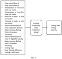
- FIG. 4 A schematic block diagram illustrating a thermal properties model is shown in FIG. 4 .
- the thermal properties model comprises of the data driven model.
- the model uses an inlet temperature measurement of feed as input to predict the thermal properties of the feeds of the heat exchanger.
- Thermal properties of feeds comprise of heat capacity, kinematic viscosity, specific gravity and so on.
- Thermal properties model can be distinct for each feed of the heat exchanger.
- the heat transfer efficiency model comprises of the first principle-based models and the data driven models.
- the heat transfer efficiency model may also comprise of a physics-based model that solves differential equations representing the flow, and heat transfer involved in the heat exchanger heat transfer process.
- the model uses the preprocessed operation data (real time sensor data for flow rates of feeds, temperature measurement of feeds), design data of heat exchangers (geometry, material thermo-physical properties), predicted thermal properties of feeds as input for prediction of outlet temperatures of feeds and heat transfer efficiency of the heat exchanger.
- the fouling type prediction model comprises either or combination of data driven models, knowledge-based models, and rule-based models.
- the model uses the preprocessed operation data (real time sensor data for flow rates of feeds, temperature measurement of feeds, pressure measurement of feeds), design data of heat exchangers (geometry, material thermo-physical properties), predicted thermal properties of feeds, thermal efficiency of the heat exchanger as input.
- This model predicts, the type of fouling heat exchanger undergoes in real time for the heat exchanger.
- the fouling type prediction model can be distinct for distinct heat exchanger in the heat exchanger network.
- the fouling parameter estimation model comprises either or combination of the data driven models, the knowledge-based models, and the rule-based models.
- the model uses the preprocessed operation data (real time sensor data for flow rates of feeds, temperature measurement of feeds, pressure measurement of feeds), design data of heat exchangers (geometry, material thermo-physical properties), predicted thermal properties of feeds, predicted fouling type, thermal efficiency of the heat exchanger as input.
- This model predicts, fouling coefficients for each heat exchanger of the heat exchanger network.
- the fouling coefficient for the heat exchanger comprises of fouling deposition coefficient, fouling suppression coefficient, fouling activation energy, ageing pre-exponential parameter, ageing activation energy.
- the predicted fouling coefficients are further used as input parameters for the fouling propensity index prediction model.
- the fouling parameter estimation model can be distinct for distinct heat exchanger in the heat exchanger network.
- the fouling propensity index prediction model comprises either or combination of first principle-based models, data driven models, knowledge-based models, and rule-based models.
- the model uses the preprocessed operation data (real time sensor data for flow rates of feeds, temperature measurement of feeds, pressure measurement of feeds), design data of heat exchangers (geometry, material thermo-physical properties), predicted thermal properties of feeds, predicted fouling type, predicted fouling coefficients and thermal efficiency of the heat exchanger as input. This model predicts, fouling rate and fouling severity for the heat exchanger.
- the fouling propensity index prediction model can be distinct for distinct heat exchanger in the heat exchanger network.
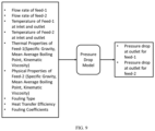
- the pressure drop model comprises either or combination of first principle-based models, data driven models, knowledge-based models, and rule-based models.
- the model uses the preprocessed operation data (real time sensor data for flow rates of feeds, temperature measurement of feeds), design data of heat exchangers (geometry, material thermo-physical properties), predicted thermal properties of feeds, predicted fouling type, predicted fouling coefficients and thermal efficiency of the heat exchanger as input. This model predicts, pressure drop for feeds of the heat exchanger.
- the pressure drop model can be distinct for distinct heat exchanger in the heat exchanger network.
- the system 100 comprises the observer unit 122.
- the observer unit 122 is configured to soft sense, a plurality of operating parameters, a plurality of fouling parameters and a fouling propensity index for each heat exchanger amongst the plurality of heat exchangers using models present in the observer unit 122.
- a flowchart 300 illustrating the steps involved in the observer unit 122 is shown in FIG. 3 .
- the observer unit 122 is also configured to interface with internal/external tools/models available in the system 100 for improved predictions.
- the system 100 comprises the analyzer unit 124.
- the analyzer unit 124 configured to detecting in real-time, a root cause of fouling by comparing the soft sensed plurality of operating parameters, the plurality of fouling parameters and the fouling propensity index using a set of predefined knowledge-based rules present in the analyzer unit 124.
- the analyzer unit 124 diagnoses operating regime changes, working fluid property variations and chemical/mechanical changes of fouling.
- the system 100 also comprises the predictor unit 126.
- the predictor unit 126 is configured to forecast, the fouling propensity index for a predefined forecast horizon for each heat exchanger amongst the plurality of heat exchangers using a plurality of forecast models present in the predictor unit 126.
- the plurality of forecast models is pre-built using the historically detected root cause of fouling and the soft sensed plurality of operating parameters and the plurality of fouling parameters.
- the fouling propensity index is indicative of the long term forecast for key fouling indicators of heat exchanger such as but not limited to fouling severity and fouling rate.
- the predictor unit 126 may also forecast pressure drop in heat exchanger and thermal performance of heat exchanger.
- the predictor unit 126 is also configured to find a remaining useful life (RUL) of each heat exchanger amongst the plurality of heat exchangers using the forecasted fouling propensity index for the predefined forecast horizon remaining useful operational life of the heat exchanger.
- RUL remaining useful life
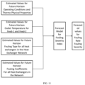
- FIG. 10 is a flowchart 1000 illustrating steps involved in forecasting the fouling rate and the fouling severity over a predefined forecasting horizon t f and calculation of RUL of the heat exchanger.
- the preprocessed data from the data transformation unit 120 and the soft sensed data from the observer unit 122 are transformed appropriately. This transformation may comprise merging data, down sampling the data, appropriate scaling, removing outliers and cleaning the data.
- the operating parameters for the predefined forecast horizon t f are estimated.
- the plurality of operating parameters comprises of flow rates of feeds, inlet temperature of feeds for each heat exchanger in heat exchanger network.
- the thermal properties of the feeds are estimated using estimated plurality of operating parameters using the thermal properties model in the observer unit 122 for the predefined forecast horizon for each heat exchanger in heat exchanger network.
- the temperatures of feeds are estimated at an outlet of each heat exchanger using the estimated thermal properties, the estimated plurality of operating parameters and design data of heat exchanger using the heat transfer efficiency model in the observer unit 122 in the heat exchanger network.
- the fouling type is predicted using the estimated plurality of operating parameters, the estimated thermal properties, the estimated outlet temperatures using the fouling type prediction model of the observer unit 122 for each heat exchanger in heat exchanger network.
- fouling coefficients are predicted for future horizon using the estimated plurality of operating parameters, the estimated thermal properties, the estimated outlet temperatures, the estimated fouling type, and the estimated heat transfer efficiency using the fouling parameter estimation model for each heat exchanger in heat exchanger network.
- a fouling rate and the fouling severity is forecasted using the forecast model for the fouling severity index for each heat exchanger in heat exchanger network.
- Each heat exchanger in heat exchanger network may have distinct forecast model for fouling severity index.
- Input of the forecast model for fouling severity index comprise of the estimated data for the predefined forecast horizon and historical data of operation parameters, thermal properties of feeds, outlet temperatures of feeds of a heat exchanger in network and estimated data for forecast horizon and historical data of fouling type, fouling coefficients of all heat exchangers in network.
- the remaining useful life is calculated using the forecasted fouling rate and the fouling severity for the heat exchanger in heat exchanger network.
- FIG. 11 illustrates a block diagram of the forecast Model for calculating fouling severity index.
- Historical data and estimated values for future horizon for operation condition, thermo physical properties of feeds, outlet temperatures of feeds of a heat exchanger and historical data along with estimated values for future horizon for fouling type and fouling coefficients for all heat exchangers in network are used as input for the forecast model for the fouling severity index.
- Output of this model comprise of fouling severity and the fouling rate in the heat exchanger.
- Forecast model for the fouling severity index can be distinct for distinct heat exchangers in the network. Forecast of fouling rate and fouling severity is performed for each heat exchanger in the heat exchanger network.
- the system 100 comprises the recommender unit 128.
- the recommender 128 unit is configured to recommend, one or more of activity based on a set of forecasted parameters, operation constraint parameters and the RUL of each of the heat exchangers.
- the one or more activity comprises a cleaning and maintenance schedule of one or more of heat exchanger, or a set of operational changes in the one or more heat exchangers to increase the RUL.
- the recommendations are based on current and expected fouling conditions for optimizing efficiency, minimizing costs etc. Further, scheduling and maintenance advises are based on the forecast of fouling trends.
- the system 100 can also advise deployment of additional sensors at appropriate locations for increasing accuracy of fouling identification.
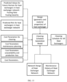
- FIG 12 is a flowchart 1200 illustrating the steps for generation of cleaning schedule and operation recommendation in the recommender unit 128.
- forecasted data for fouling severity and the fouling rate of each heat exchanger in the heat exchanger network is obtained from the prediction unit 126.
- an optimal cleaning schedule is generated using a cleaning schedule generation model using forecasted fouling severity and rate, predicted RLTL, design data, and maintenance history of each heat exchanger in the heat exchanger network and cost parameters data.
- Cost parameters data comprises of cost parameter for cleaning, maintenance planning, unavailability of the heat exchanger, and production loss due to unavailability of the heat exchanger.
- step 1206 type of cleaning to be performed for each heat exchanger is recommended to the operator based on the cleaning schedule generation model and the fouling severity data.
- Operation recommendation can be generated using knowledge-based model.
- operation recommendations are provided to the user based on the optimal cleaning schedule generated using a knowledge-based model. For example, based on optimal cleaning schedule system may suggest changes in feed flow rates in heat exchanger network to operator.
- FIG. 13 shows a block diagram of the recommender unit 128 using the cleaning schedule generation model.
- the cleaning schedule generation model comprises model based on either or combination of deep learning algorithm, reinforcement learning algorithm and optimization algorithm.
- Input for the cleaning schedule generation model comprise of forecasted fouling severity and rate for each heat exchanger in the heat exchanger network from the predictor unit 126, predicted RUL for each heat exchanger in the heat exchanger network form the predictor unit 126. design of heat exchangers in the heat exchanger network, network design of the heat exchanger network, maintenance history of heat exchanger network and cost parameters (cleaning, maintenance planning, unavailability, and production loss).
- FIG. 14 flow diagram of a method 1400 for identification and forecasting fouling of a plurality of heat exchangers in the refinery 102 is described in accordance with an example embodiment.
- the method 1400 depicted in the flow chart may be executed by a system, for example, the system, 100 of FIG. 1 .
- the system 100 may be embodied in the computing device as explained above.
- Operations of the flowchart, and combinations of operation in the flowchart may be implemented by various means, such as hardware, firmware, processor, circuitry and/or other device associated with execution of software including one or more computer program instructions.
- one or more of the procedures described in various embodiments may be embodied by computer program instructions.
- the computer program instructions, which embody the procedures, described in various embodiments may be stored by at least one memory device of a system and executed by at least one processor in the system. Any such computer program instructions may be loaded onto a computer or other programmable system (for example, hardware) to produce a machine, such that the resulting computer or other programmable system embody means for implementing the operations specified in the flowchart.
- the operations of the method 1400 are described with help of system 100. However, the operations of the method 1400 can be described and/or practiced by using any other system.
- a plurality of data related to the heat exchangers network is received from a plurality of data sources 134, wherein the network comprises the plurality of heat exchangers in the refinery 102.
- the received plurality of data is preprocessed and transformed.
- the plurality of operating parameters, the plurality of fouling parameters and the fouling propensity index is soft sensed for each heat exchanger amongst the plurality of heat exchangers using models present in the observer unit 122.
- a root cause of fouling is detected in real-time, by comparing the soft sensed plurality of operating parameters, the plurality of fouling parameters and the fouling propensity index using a set of predefined knowledge-based rules present in the analyzer unit 124.
- the fouling propensity index is forecasted for the predefined forecast horizon for each heat exchanger amongst the plurality of heat exchangers using a plurality of forecast models present in the predictor unit 126, wherein the plurality of forecast models is pre-built using the historically detected root cause of fouling and the soft sensed plurality of operating parameters and the plurality of fouling parameters.
- a remaining useful life (RLTL) of each heat exchanger amongst the plurality of heat exchangers is obtained using the forecasted fouling propensity index for the predefined forecast horizon.
- one or more of activities is recommended based on a set of parameters and the RUL of each of the heat exchangers, wherein the one or more activities comprises: a cleaning and maintenance schedule of one or more of heat exchanger, or a set of operational changes in the one or more heat exchangers to increase the RUL.
- the system 100 comprises the simulator unit 130.
- the simulator unit 130 is configured to simulate and understand the impact of 'what if' and 'if-what' scenarios for heat exchanger for e.g. refinery operator can forecast the fouling characteristics for different types of crude oil blends.
- the system 100 comprises the model update unit 132.
- the model update unit 132 enables automatic update of models if performance of the models is below a set threshold.
- the plurality of units used in the system comprises of specific models to carry out the intended tasks. This unit assist in calibrating existing models for prediction of fouling and other parameters with respect to the current performance of the heat exchangers. This may also comprise of tools for adapting a model built for a specific heat exchanger to another heat exchanger in the train or in other refinery.
- the plurality of units can work in online or offline mode as per the requirement. Some of the units may operate online in the background or some may work online in real-time.
- This system 100 can be applied to heat exchangers used in oil refinery as well as any other heat exchangers experiencing similar fouling, for example, heat exchangers in pre-heat train of refinery, transfer line exchangers in refinery.
- the system 100 may also include optimization solvers and reinforcement learning techniques for optimal control.
- the models could in turn interface with external models/tools, may receive inputs/outputs and may iterate over them.
- the plurality of units is supported by an interactive user interface that can be used to provide external inputs, receive outputs/recommendations, visualizations of analytics.
- the embodiments of present disclosure herein address unresolved problem of costs and effort involved in the maintenance of heat exchangers in the refinery.
- the embodiment thus provides a method and system for identification and forecasting fouling of a plurality of heat exchangers in a refinery
- the hardware device can be any kind of device which can be programmed including e.g. any kind of computer like a server or a personal computer, or the like, or any combination thereof.
- the device may also include means which could be e.g. hardware means like e.g. an application-specific integrated circuit (ASIC), a field-programmable gate array (FPGA), or a combination of hardware and software means, e.g.
- ASIC application-specific integrated circuit
- FPGA field-programmable gate array
- the means can include both hardware means and software means.
- the method embodiments described herein could be implemented in hardware and software.
- the device may also include software means.
- the embodiments may be implemented on different hardware devices, e.g. using a plurality of CPUs.
- the embodiments herein can comprise hardware and software elements.
- the embodiments that are implemented in software include but are not limited to, firmware, resident software, microcode, etc.
- the functions performed by various components described herein may be implemented in other components or combinations of other components.
- a computer-usable or computer readable medium can be any apparatus that can comprise, store, communicate, propagate, or transport the program for use by or in connection with the instruction execution system, apparatus, or device.
- a computer-readable storage medium refers to any type of physical memory on which information or data readable by a processor may be stored.
- a computer-readable storage medium may store instructions for execution by one or more processors, including instructions for causing the processor(s) to perform steps or stages consistent with the embodiments described herein.
- the term "computer-readable medium” should be understood to include tangible items and exclude carrier waves and transient signals, i.e., be non-transitory. Examples include random access memory (RAM), read-only memory (ROM), volatile memory, nonvolatile memory, hard drives, CD ROMs, DVDs, flash drives, disks, and any other known physical storage media.
Landscapes
- Engineering & Computer Science (AREA)
- Theoretical Computer Science (AREA)
- Physics & Mathematics (AREA)
- General Engineering & Computer Science (AREA)
- General Physics & Mathematics (AREA)
- Evolutionary Computation (AREA)
- Software Systems (AREA)
- Artificial Intelligence (AREA)
- Data Mining & Analysis (AREA)
- Chemical & Material Sciences (AREA)
- Mathematical Physics (AREA)
- Computing Systems (AREA)
- Computer Vision & Pattern Recognition (AREA)
- Oil, Petroleum & Natural Gas (AREA)
- Computational Linguistics (AREA)
- Medical Informatics (AREA)
- Geometry (AREA)
- Computer Hardware Design (AREA)
- Automation & Control Theory (AREA)
- Chemical Kinetics & Catalysis (AREA)
- General Chemical & Material Sciences (AREA)
- Organic Chemistry (AREA)
- Thermal Sciences (AREA)
- Mechanical Engineering (AREA)
- Life Sciences & Earth Sciences (AREA)
- Bioinformatics & Cheminformatics (AREA)
- Bioinformatics & Computational Biology (AREA)
- Evolutionary Biology (AREA)
- Testing And Monitoring For Control Systems (AREA)
Description
- The present application claims priority from
Indian provisional patent application no. 202021040367, filed on September 17, 2020 - The disclosure herein generally relates to the field of refinery, and, more particularly, to a method and a system for identification and forecasting fouling of heat exchangers in refinery such as an oil and gas refinery.
- Fouling is formation of deposits on the heat exchanger surfaces that adversely affects a heat exchange and other functions of the heat exchanger. Crude oil from storage tanks is fed to the heat exchangers of the crude pre-heat train. Fouling occurs due one or more of combinations of various reasons such as sedimentation, crystallization, biological growth, chemical reactions, or corrosion products freezing among others.
- Most of the fouling arises from Asphaltene deposition from crude oil onto metal surfaces of the pre-heat train heat exchangers. Fouling in the refinery heat exchangers may also be caused by inorganic compounds, carbon deposition etc. For example, transfer line exchangers undergo fouling due to carbon deposition, pre-heat train heat exchangers undergo fouling due asphaltene deposition. Fouling of heat exchangers in petroleum refining industry leads to several problems such as - operating problems - decline in furnace inlet temperatures, reduced efficiency of heat recovery units, high operating costs - increased fuel consumption, high pumping power, increased carbon footprint, reduced throughput, increased maintenance costs and fouling in upstream heat exchangers.
- Fouling cannot be measured directly in real-time. It can at best be approximated through a set of estimated heat exchanger parameters. These estimations may or may not be accurate, leading to uncertainty in operation/maintenance decisions and hence the losses. Document
US 2019/145722 A1 discloses a method of controlling cooling water treatment may involve measuring operating data of one or more downstream heat exchangers that receive cooling water from the cooling tower. For example, the inlet and outlet temperatures of both the hot and cold streams of a downstream heat exchanger may be measured. Data from the streams passing through the heat exchanger may be used to determine a heat transfer efficiency for the heat exchanger. The heat transfer efficiency can be trended over a period of time and changes in the trend detected to identify cooling water fouling issues. Multiple potential causes of the perceived fouling issues can be evaluated to determine a predicted cause. A chemical additive selected to reduce, eliminate, or otherwise control the cooling water fouling can be controlled based on the predicted cause of the fouling. Further, document CHIN HON HUIN ET AL., in "Long-term investment and maintenance planning for heat exchanger network retrofit" discloses that process optimization has been the core topic in chemical process industries for decades. However, the performance of the asset strongly influences the production efficiency as well. In the case of Heat Exchanger Network (HEN), the retrofit decisions are often aimed to maximize energy savings and minimize the associated cost. However, the age and performance of heat exchangers have a great influence on the IIEN efficiency as well. This study brings innovative retrofit algorithms, integrating exchangers' lifetime and reliability functions to visualize the benefits of the hybrid process and asset optimization. The HEN retrofit structures are optimized, considering various heat intensification methods. The model is formulated based on the novel concept of Shifted Retrofit Thermodynamic Grid Diagram (SRTGD). A Mixed Integer Linear Programming (MILP) model is formulated for the investment and maintenance planning. The operating life of the network is discretized into multiple periods, and a decision is made within each period: whether to upgrade the heat exchangers, purchase new heat exchangers - for replacement or adding to the network, maintain the heat exchangers or perform nothing. Two realistic case studies are used to elucidate the application of the method. Under a 20 y planning horizon, the Net Present Value (NPV) obtained are higher than the previous works, i.e. 17% higher forcase study 1 with 51% utility savings, and 14% higher forcase study 2 with 74% utility savings. The proposed HEN retrofit decisions are proven to be cost-effective. A graphical tool has been developed to track the reliability and maintenance status of the exchangers to provide a significant guide to the economically optimum decisions. - Embodiments of the present disclosure present technological improvements as solutions to one or more of the above-mentioned technical problems recognized by the inventors in conventional systems. According to the invention, a system for identification and forecasting fouling of a plurality of heat exchangers in a refinery according to claim 11 is provided. The system comprises an input/output interface, one or more hardware processors and a memory. The memory is in communication with the one or more hardware processors, wherein the one or more first hardware processors are configured to execute programmed instructions stored in the one or more first memories, to: receive a plurality of data related to a heat exchanger network from a plurality of data sources, wherein the network comprises the plurality of heat exchangers in the refinery, characterized in that: preprocess the received plurality of data using a plurality of pre-built models present in a data transformation unit; soft sense a plurality of operating parameters, a plurality of fouling parameters and a fouling propensity index for each heat exchanger amongst the plurality of heat exchangers using pre-built models present in an observer unit, wherein the plurality of operating parameters and the plurality of fouling parameters and the fouling propensity index comprises outlet temperature of each feed of the heat exchangers, an outlet pressure of each feed of the heat exchangers, heat transfer efficiency of the heat exchangers, a fouling type comprises organic fouling and inorganic fouling, fouling coefficients, fouling rate and fouling severity of the heat exchangers; detect in real-time a root cause of fouling by comparing the soft sensed plurality of operating parameters, the plurality of fouling parameters and the fouling propensity index using a set of predefined rules present in an analyzer unit; forecast a set of forecasted parameters and forecasted fouling propensity index for a predefined forecast horizon for each heat exchanger amongst the plurality of heat exchangers using a plurality of pre-built forecast models present in a predictor unit, wherein the plurality of pre-built forecast models are build using historically detected root cause of fouling and the soft sensed plurality of operating parameters and the plurality of fouling parameters; find a remaining useful life (RLTL) of each heat exchanger amongst the plurality of heat exchangers using the forecasted fouling propensity index for the predefined forecast horizon; and recommend one or more of activities based on the set of forecasted parameters the forecasted fouling propensity index, operation constraint parameters, the RUL of each of the heat exchangers, , cost involved in cleaning and maintenance of one or more of heat exchangers, maintenance history of the heat exchanger network, wherein the operation constraint parameters comprises cost parameters data, a design specification of the heat exchangers, and a design specification of heat exchanger network, and wherein the one or more activities comprises: a cleaning and maintenance schedule of one or more of heat exchangers, or a set of operational changes in the one or more heat exchangers to increase the RLTL.
- According to the invention, a method for identification and forecasting fouling of a plurality of heat exchangers in a refinery according to
claim 1 is provided. Initially, a plurality of data is received related to a heat exchanger network from a plurality of data sources, wherein the network comprises the plurality of heat exchangers in the refinery. Characterized in that in the next step, the received plurality of data is preprocessed using a plurality of pre-built models present in a data transformation unit. Further, a plurality of operating parameters, a plurality of fouling parameters and a fouling propensity index are soft sensed for each heat exchanger amongst the plurality of heat exchangers using pre-built models present in an observer unit, wherein the plurality of operating parameters and the plurality of fouling parameters and the fouling propensity index comprises outlet temperature of each feed of the heat exchangers, an outlet pressure of each feed of the heat exchangers, heat transfer efficiency of the heat exchangers, a fouling type comprises organic fouling and inorganic fouling, fouling coefficients, fouling rate and fouling severity of the heat exchangers. A root cause of fouling is then detected by comparing the soft sensed plurality of operating parameters, the plurality of fouling parameters and the fouling propensity index using a set of predefined rules present in an analyzer unit. Further, a set of forecasted parameters and a forecasted fouling propensity index is forecasted for a predefined forecast horizon for each heat exchanger amongst the plurality of heat exchangers using a plurality of pre-built forecast models present in a predictor unit, wherein the plurality of pre-built forecast models are build using historically detected root cause of fouling and the soft sensed plurality of operating parameters and the plurality of fouling parameters. In the next step, a remaining useful life (RUL) is obtained of each heat exchanger amongst the plurality of heat exchangers using the forecasted fouling propensity index for the predefined forecast horizon.. - Finally, one or more of activities are recommended based on the set of forecasted parameters, the forecasted fouling propensity index, operation constraint parameters, the RUL of each of the heat exchangers, cost involved in cleaning and maintenance of one or more of heat exchangers, maintenance history of the heat exchanger network, wherein the operation constraint parameters comprises cost parameters data, a design specification of the heat exchangers, and a design specification of heat exchanger network, and wherein the one or more activities comprises: a cleaning and maintenance schedule of one or more of heat exchangers, or a set of operational changes in the one or more heat exchangers to increase the RLTL.
- It is to be understood that both the foregoing general description and the following detailed description are exemplary and explanatory only and are not restrictive of the invention, as claimed.
- The accompanying drawings, which are incorporated in and constitute a part of this disclosure, illustrate exemplary embodiments and, together with the description, serve to explain the disclosed principles:
-
FIG. 1 illustrates a network diagram of a system for identification and forecasting fouling of heat exchangers in oil and gas refinery according to some embodiments of the present disclosure. -
FIG. 2 is a functional block diagram of the system for identification and forecasting fouling of heat exchangers in oil and gas refinery according to some embodiments of the present disclosure. -
FIG. 3 is a flowchart illustrating steps involved in the operation of an observer model according to some embodiments of the present disclosure. -
FIG. 4 is a schematic block diagram of a thermal properties model, according to some embodiments of the present disclosure. -
FIG. 5 is a schematic block diagram of a heat transfer efficiency model, according to some embodiments of the present disclosure. -
FIG. 6 is a schematic block diagram of a fouling type prediction model, according to some embodiments of the present disclosure. -
FIG. 7 is a schematic block diagram of a fouling parameter estimation model, according to some embodiments of the present disclosure. -
FIG. 8 is a schematic block diagram of a fouling propensity index prediction model, according to some embodiments of the present disclosure. -
FIG. 9 is a schematic block diagram of a pressure drop model, according to some embodiments of the present disclosure. -
FIG. 10 is a flowchart illustrating steps involved in forecasting a fouling rate and a fouling severity over a predefined forecasting horizon according to some embodiments of the present disclosure. -
FIG. 11 is a block diagram of the forecast model for calculating the fouling severity index according to some embodiments of the present disclosure. -
FIG. 12 is a flowchart illustrating the steps involved in generating of cleaning schedule and operation recommendation according to some embodiments of the present disclosure. -
FIG. 13 is a block diagram of the recommender unit according to some embodiments of the present disclosure. -
FIG. 14 is a flow diagram illustrating method for identification and forecasting fouling of heat exchangers in oil and gas refinery in accordance with some embodiments of the present disclosure. - Exemplary embodiments are described with reference to the accompanying drawings. In the figures, the left-most digit(s) of a reference number identifies the figure in which the reference number first appears. Wherever convenient, the same reference numbers are used throughout the drawings to refer to the same or like parts.
- There are few methods that exist in the prior art for simulating the operation of heat exchangers in the oil and gas refinery. The operators are unable to predict the future course of fouling trends. This is mainly because, fouling is an unpredictable phenomenon dependent upon diverse parameters such as crude mix, crude properties, flow rates, temperatures among others. Subtle changes in crude mix may alter the course of fouling significantly due to change in dominant fouling mechanism. Therefore, there is a need for a fouling forecasting system that can estimate long term fouling trends so that appropriate operation and maintenance decisions could be taken. In addition, there is a need to provide a what-if scenario tool to the operator to identify the best course of action given the prevailing situation of fouling.
- Currently to mitigate the effects of fouling and ageing impact, heat exchangers are cleaned as per a fixed and periodic maintenance schedule. However, cleaning schedule of heat exchangers is highly dependent on rate of fouling and aging of deposits. Creating an optimal cleaning schedule considering the chain of interconnected heat exchangers is one of the major challenges. Therefore, there is a need of a real-time soft sensing of fouling conditions in a heat exchanger to assist the decision-making during operation.
- The present disclosure herein provides a system and a method for identification and forecasting fouling of a plurality of heat exchangers in a refinery. The system comprises a digital replica of the heat exchanger network (HEN) in an oil and gas refinery. The digital replica is configured to receive real-time sensor data from a plurality of data sources and provides real-time soft sensing of key parameters such as fouling severity, fouling rate, fouling type, temperatures and heat transfer efficiency, long term forecast of key fouling indicators such as differential pressure. In addition, the system is also configured to diagnose the reasons behind a specific condition of fouling. Further, an advisory is also provided, that alerts and recommends corrective actions in terms of either heat exchanger process parameters or parameters controlled through other equipment or changes in operation or design or changes in cleaning schedule. The system provides estimate for the remaining useful life (RLTL) of the heat exchangers and suggests the cleaning schedule by considering the fouling rate and severity characteristics, heat exchanger network design, heat exchanger design and maintenance history of the network as well as cost parameters.
- Referring now to the drawings, and more particularly to
FIG. 1 through FIG. 14 , where similar reference characters denote corresponding features consistently throughout the figures, there are shown preferred embodiments and these embodiments are described in the context of the following exemplary system and/or method. -
FIG. 1 illustrates a network diagram andFIG. 2 is a block diagram of asystem 100 for identification and forecasting fouling of heat exchangers in arefinery 102 such as an oil andgas refinery 102. Thesystem 100 comprises adigital replica 104 of heat exchanger in heat recovery system of oil and gas refinery. Thedigital replica 104 receives real-time sensor data from a plurality of data sources and provides real-time soft sensing of key parameters such as fouling severity, fouling rate, fouling type, temperatures and heat transfer efficiency, long term forecast of key fouling indicators such as differential pressure. - The recommendations or advice from the
digital replica 104 is directly passed onto acontrol system 106 which control the oil andgas refinery 102 for implementation, with or without any operator intervention/approval. Thesystem 100 can be deployed on edge or on cloud. Thesystem 100 is configured to diagnose the accuracy and applicability of current monitoring and forecasting models. If found unsatisfactory, thesystem 100 triggers automatic update of the models based on the data and information captured from the last update of the models. In addition, thesystem 100 is also configured to create new models for a different heat exchanger based on an existing model of a heat exchanger. - According to an embodiment of the disclosure, the block diagram of the
system 100 for identification and forecasting fouling of a plurality of heat exchangers in therefinery 102 is shown inFIG 2 . Although the present disclosure is explained considering that thesystem 100 is implemented on a server, it may also be present elsewhere such as a local machine. It may be understood that thesystem 100 comprises one ormore computing devices 108, such as a laptop computer, a desktop computer, a notebook, a workstation, a cloud-based computing environment and the like. It will be understood that thesystem 100 may be accessed through one or more input/output interfaces collectively referred to as I/O interface 110. Examples of the I/O interface 110 may include, but are not limited to, a user interface, a portable computer, a personal digital assistant, a handheld device, a smartphone, a tablet computer, a workstation and the like. The I/O interface 110 are communicatively coupled to thesystem 100 through anetwork 112. - In an embodiment, the
network 112 may be a wireless or a wired network, or a combination thereof. In an example, thenetwork 112 can be implemented as a computer network, as one of the different types of networks, such as virtual private network (VPN), intranet, local area network (LAN), wide area network (WAN), the internet, and such. Thenetwork 112 may either be a dedicated network or a shared network, which represents an association of the different types of networks that use a variety of protocols, for example, Hypertext Transfer Protocol (HTTP), Transmission Control Protocol/Internet Protocol (TCP/IP), and Wireless Application Protocol (WAP), to communicate with each other. Further, thenetwork 112 may include a variety of network devices, including routers, bridges, servers, computing devices, storage devices. The network devices within thenetwork 112 may interact with thesystem 100 through communication links. - The
system 100 may be implemented in a workstation, a mainframe computer, a server, and a network server. In an embodiment, thecomputing device 108 further comprises one ormore hardware processors 114, one ormore memory 116, hereinafter referred as amemory 116 and adata repository 118, for example, arepository 118 or adatabase 118. Thememory 116 is in communication with the one ormore hardware processors 114, wherein the one ormore hardware processors 114 are configured to execute programmed instructions stored in thememory 116, to perform various functions as explained in the later part of the disclosure. Therepository 118 may store data processed, received, and generated by thesystem 100. - The
system 100 supports various connectivity options such as BLUETOOTH®, USB, ZigBee and other cellular services. The network environment enables connection of various components of thesystem 100 using any communication link including Internet, WAN, MAN, and so on. In an exemplary embodiment, thesystem 100 is implemented to operate as a stand-alone device. In another embodiment, thesystem 100 may be implemented to work as a loosely coupled device to a smart computing environment. The components and functionalities of thesystem 100 are described further in detail. - According to an embodiment of the disclosure, the
memory 116 comprises a plurality of units. The plurality of units is a set of instructions and configured to perform a plurality of functions. The plurality of units comprises adata transformation unit 120 or adata processing unit 120, anobserver unit 122, ananalyzer unit 124, apredictor unit 126, a recommender unit 128, asimulator unit 130, and amodel update unit 132. - According to an embodiment of the disclosure, an input data is collected from a plurality of data sources 134. The plurality of data sources 134 comprises one or more of comprises a distributed control system (DCS), one or more of Supervisory Control and Data Acquisition (SCADA) System, Enterprise Resource Planning (ERP) system, a historian, a laboratory information management system (LIMS), Manufacturing Execution System (MES), Manufacturing Operations Management System (MOM), databases, a plurality of sensors, external sources, manual input and other digital systems in plant. The data can also be entered manually by the user/operator using the I/
O interface 104. The data can also be collected from a plurality of sensors installed for sensing specific operating conditions. This data and the historical data accumulated in a data historian is connected to the digital twin (on edge/cloud) through a communication interface. According to an embodiment of the disclosure, thedata repository 118 may comprise of information/data related to materials, refinery performance, maintenance information, design information, equipment information, predictive models, optimization models, operation data, processed data, recommendations/ decisions from the system, environmental parameters and expert knowledge among others. - According to an embodiment of the disclosure, the
system 100 comprises thedata transformation unit 120. Thedata transformation unit 120 is configured to receive a plurality of data from various sources and preprocess it in as per the requirement of other units. The transformation of data comprises identification and removal of outliers, imputation of missing data, and synchronization and integration of a plurality of variables from one or more data sources, transforming the plurality of data into a plurality of shapes, sizes and frequencies based on predefined forecast horizon. The sampling frequency of real-time and non-real-time data may be unified to, for example, once every 1 min, where the real-time data is averaged as necessary and the non-real-time data is interpolated or replicated as necessary. Additional data transformation required for specific units can also be performed. - The plurality of data comprises of feed flow rates, feed temperatures and feed pressure measurement at inlet of the heat exchanger, design data of the heat exchanger, design of the heat exchanger network. The feed temperature measurement data is used by a thermal properties model to predict thermal properties of feeds. Thermal properties of feeds are predicted separately for each heat exchanger in the heat exchanger network. The thermal properties of feed comprise of heat capacity, kinematic viscosity, specific gravity and so on. The processed plurality of data along with various other information is used for various purposes as follows:
- The preprocessed plurality of data, thermal properties of feeds, heat exchanger design data are used as input for a heat transfer efficiency model to predict outlet temperatures of the feeds and a heat transfer efficiency of the heat exchanger in real time for each heat exchanger in the heat exchanger network separately.
- Preprocessed plurality of data, thermal properties of feeds, the outlet temperature of the feeds are used as input for a fouling type prediction model to predict the fouling type for each heat exchanger in heat exchanger network.
- Preprocessed data, thermal properties of feeds, outlet temperature of feeds and fouling type are used as input to a fouling parameter estimation model to predict in real time the fouling coefficients for each heat exchanger in heat exchanger network separately. Fouling coefficient for heat exchanger comprises of fouling deposition coefficient, fouling suppression coefficient, fouling activation energy, ageing pre-exponential parameter, ageing activation energy.
- Preprocessed data, thermal properties of feeds, the outlet temperature of feeds, the thermal efficiency, the fouling type, the fouling coefficients are used as input for real time prediction of fouling rate and fouling severity using a fouling propensity index prediction model for each heat exchanger in the heat exchanger network.
- A pressure drop model is used to soft sense the outlet pressure of feeds for each heat exchanger in heat exchanger network. Input of pressure drop model comprises of preprocessed data, thermal properties of feeds, outlet temperature of feeds, thermal efficiency, fouling type, fouling coefficients.
- A schematic block diagram illustrating a thermal properties model is shown in
FIG. 4 . The thermal properties model comprises of the data driven model. The model uses an inlet temperature measurement of feed as input to predict the thermal properties of the feeds of the heat exchanger. Thermal properties of each feed of heat exchanger in heat exchanger network. Thermal properties of feeds comprise of heat capacity, kinematic viscosity, specific gravity and so on. Thermal properties model can be distinct for each feed of the heat exchanger. - A schematic block diagram illustrating the heat transfer efficiency model is shown
FIG. 5 . The heat transfer efficiency model comprises of the first principle-based models and the data driven models. In an embodiment of this disclosure, the heat transfer efficiency model may also comprise of a physics-based model that solves differential equations representing the flow, and heat transfer involved in the heat exchanger heat transfer process. The model uses the preprocessed operation data (real time sensor data for flow rates of feeds, temperature measurement of feeds), design data of heat exchangers (geometry, material thermo-physical properties), predicted thermal properties of feeds as input for prediction of outlet temperatures of feeds and heat transfer efficiency of the heat exchanger. - A schematic block diagram illustrating the fouling type prediction model is shown
FIG. 6 . The fouling type prediction model comprises either or combination of data driven models, knowledge-based models, and rule-based models. The model uses the preprocessed operation data (real time sensor data for flow rates of feeds, temperature measurement of feeds, pressure measurement of feeds), design data of heat exchangers (geometry, material thermo-physical properties), predicted thermal properties of feeds, thermal efficiency of the heat exchanger as input. This model predicts, the type of fouling heat exchanger undergoes in real time for the heat exchanger. The fouling type prediction model can be distinct for distinct heat exchanger in the heat exchanger network. - A schematic block diagram illustrating the fouling parameter estimation model is shown
FIG. 7 . The fouling parameter estimation model comprises either or combination of the data driven models, the knowledge-based models, and the rule-based models. The model uses the preprocessed operation data (real time sensor data for flow rates of feeds, temperature measurement of feeds, pressure measurement of feeds), design data of heat exchangers (geometry, material thermo-physical properties), predicted thermal properties of feeds, predicted fouling type, thermal efficiency of the heat exchanger as input. This model predicts, fouling coefficients for each heat exchanger of the heat exchanger network. The fouling coefficient for the heat exchanger comprises of fouling deposition coefficient, fouling suppression coefficient, fouling activation energy, ageing pre-exponential parameter, ageing activation energy. The predicted fouling coefficients are further used as input parameters for the fouling propensity index prediction model. The fouling parameter estimation model can be distinct for distinct heat exchanger in the heat exchanger network. - A schematic block diagram illustrating the fouling propensity index prediction model is shown
FIG. 8 . The fouling propensity index prediction model comprises either or combination of first principle-based models, data driven models, knowledge-based models, and rule-based models. The model uses the preprocessed operation data (real time sensor data for flow rates of feeds, temperature measurement of feeds, pressure measurement of feeds), design data of heat exchangers (geometry, material thermo-physical properties), predicted thermal properties of feeds, predicted fouling type, predicted fouling coefficients and thermal efficiency of the heat exchanger as input. This model predicts, fouling rate and fouling severity for the heat exchanger. The fouling propensity index prediction model can be distinct for distinct heat exchanger in the heat exchanger network. - A schematic block diagram illustrating the pressure drop model is shown
FIG. 9 . The pressure drop model comprises either or combination of first principle-based models, data driven models, knowledge-based models, and rule-based models. The model uses the preprocessed operation data (real time sensor data for flow rates of feeds, temperature measurement of feeds), design data of heat exchangers (geometry, material thermo-physical properties), predicted thermal properties of feeds, predicted fouling type, predicted fouling coefficients and thermal efficiency of the heat exchanger as input. This model predicts, pressure drop for feeds of the heat exchanger. The pressure drop model can be distinct for distinct heat exchanger in the heat exchanger network. - According to an embodiment of the disclosure the
system 100 comprises theobserver unit 122. Theobserver unit 122 is configured to soft sense, a plurality of operating parameters, a plurality of fouling parameters and a fouling propensity index for each heat exchanger amongst the plurality of heat exchangers using models present in theobserver unit 122. Aflowchart 300 illustrating the steps involved in theobserver unit 122 is shown inFIG. 3 . In addition, theobserver unit 122 is also configured to interface with internal/external tools/models available in thesystem 100 for improved predictions. - According to an embodiment of the disclosure the
system 100 comprises theanalyzer unit 124. Theanalyzer unit 124 configured to detecting in real-time, a root cause of fouling by comparing the soft sensed plurality of operating parameters, the plurality of fouling parameters and the fouling propensity index using a set of predefined knowledge-based rules present in theanalyzer unit 124. Theanalyzer unit 124 diagnoses operating regime changes, working fluid property variations and chemical/mechanical changes of fouling. - According to an embodiment of the disclosure the
system 100 also comprises thepredictor unit 126. Thepredictor unit 126 is configured to forecast, the fouling propensity index for a predefined forecast horizon for each heat exchanger amongst the plurality of heat exchangers using a plurality of forecast models present in thepredictor unit 126. The plurality of forecast models is pre-built using the historically detected root cause of fouling and the soft sensed plurality of operating parameters and the plurality of fouling parameters. The fouling propensity index is indicative of the long term forecast for key fouling indicators of heat exchanger such as but not limited to fouling severity and fouling rate. In another example, thepredictor unit 126 may also forecast pressure drop in heat exchanger and thermal performance of heat exchanger. - According to an embodiment of the disclosure, the
predictor unit 126 is also configured to find a remaining useful life (RUL) of each heat exchanger amongst the plurality of heat exchangers using the forecasted fouling propensity index for the predefined forecast horizon remaining useful operational life of the heat exchanger. - The fouling propensity index can also be indicated by the forecasting fouling rate and fouling severity.
FIG. 10 is aflowchart 1000 illustrating steps involved in forecasting the fouling rate and the fouling severity over a predefined forecasting horizon tf and calculation of RUL of the heat exchanger. Atstep 1002, the preprocessed data from thedata transformation unit 120 and the soft sensed data from theobserver unit 122 are transformed appropriately. This transformation may comprise merging data, down sampling the data, appropriate scaling, removing outliers and cleaning the data. Atstep 1004, the operating parameters for the predefined forecast horizon tf are estimated. The plurality of operating parameters comprises of flow rates of feeds, inlet temperature of feeds for each heat exchanger in heat exchanger network. Atstep 1006, the thermal properties of the feeds are estimated using estimated plurality of operating parameters using the thermal properties model in theobserver unit 122 for the predefined forecast horizon for each heat exchanger in heat exchanger network. Atstep 1008, the temperatures of feeds are estimated at an outlet of each heat exchanger using the estimated thermal properties, the estimated plurality of operating parameters and design data of heat exchanger using the heat transfer efficiency model in theobserver unit 122 in the heat exchanger network. At step 1010 the fouling type is predicted using the estimated plurality of operating parameters, the estimated thermal properties, the estimated outlet temperatures using the fouling type prediction model of theobserver unit 122 for each heat exchanger in heat exchanger network. Atstep 1012, fouling coefficients are predicted for future horizon using the estimated plurality of operating parameters, the estimated thermal properties, the estimated outlet temperatures, the estimated fouling type, and the estimated heat transfer efficiency using the fouling parameter estimation model for each heat exchanger in heat exchanger network. At step 1014 a fouling rate and the fouling severity is forecasted using the forecast model for the fouling severity index for each heat exchanger in heat exchanger network. Each heat exchanger in heat exchanger network may have distinct forecast model for fouling severity index. Input of the forecast model for fouling severity index comprise of the estimated data for the predefined forecast horizon and historical data of operation parameters, thermal properties of feeds, outlet temperatures of feeds of a heat exchanger in network and estimated data for forecast horizon and historical data of fouling type, fouling coefficients of all heat exchangers in network. And finally, atstep 1016, the remaining useful life is calculated using the forecasted fouling rate and the fouling severity for the heat exchanger in heat exchanger network. - According to an embodiment of the disclosure,
FIG. 11 illustrates a block diagram of the forecast Model for calculating fouling severity index. Historical data and estimated values for future horizon for operation condition, thermo physical properties of feeds, outlet temperatures of feeds of a heat exchanger and historical data along with estimated values for future horizon for fouling type and fouling coefficients for all heat exchangers in network are used as input for the forecast model for the fouling severity index. Output of this model comprise of fouling severity and the fouling rate in the heat exchanger. Forecast model for the fouling severity index can be distinct for distinct heat exchangers in the network. Forecast of fouling rate and fouling severity is performed for each heat exchanger in the heat exchanger network. - According to an embodiment of the disclosure the
system 100 comprises the recommender unit 128. The recommender 128 unit is configured to recommend, one or more of activity based on a set of forecasted parameters, operation constraint parameters and the RUL of each of the heat exchangers. The one or more activity comprises a cleaning and maintenance schedule of one or more of heat exchanger, or a set of operational changes in the one or more heat exchangers to increase the RUL. The recommendations are based on current and expected fouling conditions for optimizing efficiency, minimizing costs etc. Further, scheduling and maintenance advises are based on the forecast of fouling trends. In addition, thesystem 100 can also advise deployment of additional sensors at appropriate locations for increasing accuracy of fouling identification. -
FIG 12 is aflowchart 1200 illustrating the steps for generation of cleaning schedule and operation recommendation in the recommender unit 128. Atstep 1202, forecasted data for fouling severity and the fouling rate of each heat exchanger in the heat exchanger network is obtained from theprediction unit 126. Atstep 1204, an optimal cleaning schedule is generated using a cleaning schedule generation model using forecasted fouling severity and rate, predicted RLTL, design data, and maintenance history of each heat exchanger in the heat exchanger network and cost parameters data. Cost parameters data comprises of cost parameter for cleaning, maintenance planning, unavailability of the heat exchanger, and production loss due to unavailability of the heat exchanger. Atstep 1206, type of cleaning to be performed for each heat exchanger is recommended to the operator based on the cleaning schedule generation model and the fouling severity data. Operation recommendation can be generated using knowledge-based model. And finally, atstep 1208, operation recommendations are provided to the user based on the optimal cleaning schedule generated using a knowledge-based model. For example, based on optimal cleaning schedule system may suggest changes in feed flow rates in heat exchanger network to operator. -
FIG. 13 shows a block diagram of the recommender unit 128 using the cleaning schedule generation model. The cleaning schedule generation model comprises model based on either or combination of deep learning algorithm, reinforcement learning algorithm and optimization algorithm. Input for the cleaning schedule generation model comprise of forecasted fouling severity and rate for each heat exchanger in the heat exchanger network from thepredictor unit 126, predicted RUL for each heat exchanger in the heat exchanger network form thepredictor unit 126. design of heat exchangers in the heat exchanger network, network design of the heat exchanger network, maintenance history of heat exchanger network and cost parameters (cleaning, maintenance planning, unavailability, and production loss). - In operation, referring to
FIG. 14 , flow diagram of amethod 1400 for identification and forecasting fouling of a plurality of heat exchangers in therefinery 102 is described in accordance with an example embodiment. Themethod 1400 depicted in the flow chart may be executed by a system, for example, the system, 100 ofFIG. 1 . In an example embodiment, thesystem 100 may be embodied in the computing device as explained above. - Operations of the flowchart, and combinations of operation in the flowchart, may be implemented by various means, such as hardware, firmware, processor, circuitry and/or other device associated with execution of software including one or more computer program instructions. For example, one or more of the procedures described in various embodiments may be embodied by computer program instructions. In an example embodiment, the computer program instructions, which embody the procedures, described in various embodiments may be stored by at least one memory device of a system and executed by at least one processor in the system. Any such computer program instructions may be loaded onto a computer or other programmable system (for example, hardware) to produce a machine, such that the resulting computer or other programmable system embody means for implementing the operations specified in the flowchart. It will be noted herein that the operations of the
method 1400 are described with help ofsystem 100. However, the operations of themethod 1400 can be described and/or practiced by using any other system. - Initially at
step 1402, a plurality of data related to the heat exchangers network is received from a plurality of data sources 134, wherein the network comprises the plurality of heat exchangers in therefinery 102. Atstep 1404, the received plurality of data is preprocessed and transformed. Atstep 1406, the plurality of operating parameters, the plurality of fouling parameters and the fouling propensity index is soft sensed for each heat exchanger amongst the plurality of heat exchangers using models present in theobserver unit 122. Further atstep 1408, a root cause of fouling is detected in real-time, by comparing the soft sensed plurality of operating parameters, the plurality of fouling parameters and the fouling propensity index using a set of predefined knowledge-based rules present in theanalyzer unit 124. - At
step 1410 of themethod 1400, the fouling propensity index is forecasted for the predefined forecast horizon for each heat exchanger amongst the plurality of heat exchangers using a plurality of forecast models present in thepredictor unit 126, wherein the plurality of forecast models is pre-built using the historically detected root cause of fouling and the soft sensed plurality of operating parameters and the plurality of fouling parameters. Atstep 1412, a remaining useful life (RLTL) of each heat exchanger amongst the plurality of heat exchangers is obtained using the forecasted fouling propensity index for the predefined forecast horizon. And finally, atstep 1414, one or more of activities is recommended based on a set of parameters and the RUL of each of the heat exchangers, wherein the one or more activities comprises: a cleaning and maintenance schedule of one or more of heat exchanger, or a set of operational changes in the one or more heat exchangers to increase the RUL. - According to an embodiment of the disclosure the
system 100 comprises thesimulator unit 130. Thesimulator unit 130 is configured to simulate and understand the impact of 'what if' and 'if-what' scenarios for heat exchanger for e.g. refinery operator can forecast the fouling characteristics for different types of crude oil blends. - According to an embodiment of the disclosure the
system 100 comprises themodel update unit 132. Themodel update unit 132 enables automatic update of models if performance of the models is below a set threshold. The plurality of units used in the system comprises of specific models to carry out the intended tasks. This unit assist in calibrating existing models for prediction of fouling and other parameters with respect to the current performance of the heat exchangers. This may also comprise of tools for adapting a model built for a specific heat exchanger to another heat exchanger in the train or in other refinery. - It should be appreciated that the plurality of units can work in online or offline mode as per the requirement. Some of the units may operate online in the background or some may work online in real-time. This
system 100 can be applied to heat exchangers used in oil refinery as well as any other heat exchangers experiencing similar fouling, for example, heat exchangers in pre-heat train of refinery, transfer line exchangers in refinery. Thesystem 100 may also include optimization solvers and reinforcement learning techniques for optimal control. The models could in turn interface with external models/tools, may receive inputs/outputs and may iterate over them. The plurality of units is supported by an interactive user interface that can be used to provide external inputs, receive outputs/recommendations, visualizations of analytics. - The written description describes the subject matter herein to enable any person skilled in the art to make and use the embodiments. The scope of the subject matter embodiments is defined by the claims and may include other modifications that occur to those skilled in the art. Such other modifications are intended to be within the scope of the claims if they have similar elements that do not differ from the literal language of the claims or if they include equivalent elements with insubstantial differences from the literal language of the claims.
- The embodiments of present disclosure herein address unresolved problem of costs and effort involved in the maintenance of heat exchangers in the refinery. The embodiment, thus provides a method and system for identification and forecasting fouling of a plurality of heat exchangers in a refinery
- It is to be understood that the scope of the protection is extended to such a program and in addition to a computer-readable means having a message therein; such computer-readable storage means contain program-code means for implementation of one or more steps of the method, when the program runs on a server or mobile device or any suitable programmable device. The hardware device can be any kind of device which can be programmed including e.g. any kind of computer like a server or a personal computer, or the like, or any combination thereof. The device may also include means which could be e.g. hardware means like e.g. an application-specific integrated circuit (ASIC), a field-programmable gate array (FPGA), or a combination of hardware and software means, e.g. an ASIC and an FPGA, or at least one microprocessor and at least one memory with software processing components located therein. Thus, the means can include both hardware means and software means. The method embodiments described herein could be implemented in hardware and software. The device may also include software means. Alternatively, the embodiments may be implemented on different hardware devices, e.g. using a plurality of CPUs.
- The embodiments herein can comprise hardware and software elements. The embodiments that are implemented in software include but are not limited to, firmware, resident software, microcode, etc. The functions performed by various components described herein may be implemented in other components or combinations of other components. For the purposes of this description, a computer-usable or computer readable medium can be any apparatus that can comprise, store, communicate, propagate, or transport the program for use by or in connection with the instruction execution system, apparatus, or device.
- The illustrated steps are set out to explain the exemplary embodiments shown, and it should be anticipated that ongoing technological development will change the manner in which particular functions are performed. These examples are presented herein for purposes of illustration, and not limitation. Further, the boundaries of the functional building blocks have been arbitrarily defined herein for the convenience of the description. Alternative boundaries can be defined so long as the specified functions and relationships thereof are appropriately performed. Alternatives (including equivalents, extensions, variations, deviations, etc., of those described herein) will be apparent to persons skilled in the relevant art(s) based on the teachings contained herein. Such alternatives fall within the scope of the disclosed embodiments. Also, the words "comprising," "having," "containing," and "including," and other similar forms are intended to be equivalent in meaning and be open ended in that an item or items following any one of these words is not meant to be an exhaustive listing of such item or items, or meant to be limited to only the listed item or items. It must also be noted that as used herein and in the appended claims, the singular forms "a," "an," and "the" include plural references unless the context clearly dictates otherwise.
- Furthermore, one or more computer-readable storage media may be utilized in implementing embodiments consistent with the present disclosure. A computer-readable storage medium refers to any type of physical memory on which information or data readable by a processor may be stored. Thus, a computer-readable storage medium may store instructions for execution by one or more processors, including instructions for causing the processor(s) to perform steps or stages consistent with the embodiments described herein. The term "computer-readable medium" should be understood to include tangible items and exclude carrier waves and transient signals, i.e., be non-transitory. Examples include random access memory (RAM), read-only memory (ROM), volatile memory, nonvolatile memory, hard drives, CD ROMs, DVDs, flash drives, disks, and any other known physical storage media.
- It is intended that the disclosure and examples be considered as exemplary only, with a true scope of disclosed embodiments being indicated by the following claims.
Claims (11)
- A processor implemented method (1400) for identification and forecasting fouling of a plurality of heat exchangers in a refinery, the method comprising:receiving, via one or more hardware processors, a plurality of data related to a heat exchanger network from a plurality of data sources, wherein the heat exchanger network comprises a plurality of heat exchangers in the refinery (1402),preprocessing, via the one or more hardware processors, the received plurality of data using a plurality of pre-built models present in a data transformation unit (1404); the method being characterized by:soft sensing, via the one or more hardware processors, a plurality of operating parameters, a plurality of fouling parameters and a fouling propensity index for each heat exchanger amongst the plurality of heat exchangers using pre-built models present in an observer unit (1406), wherein the plurality of operating parameters and the plurality of fouling parameters and the fouling propensity index comprise outlet temperature of each feed of the heat exchangers, an outlet pressure of each feed of the heat exchangers, heat transfer efficiency of the heat exchangers, a fouling type comprising organic fouling and inorganic fouling, fouling coefficients, fouling rate and fouling severity of the heat exchangers;detecting in real-time, via the one or more hardware processors, a root cause of fouling by comparing the soft sensed plurality of operating parameters, the plurality of fouling parameters and the fouling propensity index using a set of predefined rules present in an analyzer unit (1408);forecasting, via the one or more hardware processors, a set of forecasted parameters and a forecasted fouling propensity index for a predefined forecast horizon for each heat exchanger amongst the plurality of heat exchangers using a plurality of pre-built forecast models present in a predictor unit (1410), wherein the plurality of pre-built forecast models are build using historically detected root cause of fouling and the soft sensed plurality of operating parameters and the plurality of fouling parameters;finding, via the one or more hardware processors, a remaining useful life, RUL, of each heat exchanger amongst the plurality of heat exchangers using the forecasted fouling propensity index for the predefined forecast horizon (1412); andrecommending, via the one or more hardware processors, one or more of activities based on the set of forecasted parameters, the forecasted fouling propensity index, operation constraint parameters, the RUL of each of the heat exchangers, cost involved in cleaning and maintenance of one or more of the heat exchangers, maintenance history of the heat exchanger network, wherein the operation constraint parameters comprise cost parameters data, a design specification of the heat exchangers, and a design specification of the heat exchanger network, and wherein the one or more activities comprises:a cleaning and maintenance schedule of one or more of the heat exchangers, ora set of operational changes in the one or more heat exchangers to increase the RUL (1414).
- The method according to claim 1 further comprises enabling automatic update of the plurality of pre-built models and the plurality of pre-built forecast models if performance of the plurality of pre-built models and the plurality of pre-built forecast models is below a set threshold.
- The method according to claim 1, wherein the plurality of operating parameters comprises feed temperature, feed pressure, feed flow rate, thermo-physical properties of feeds for the plurality of heat exchangers in the heat exchanger network.
- The method according to claim 1, wherein the plurality of data comprises:real time operating parameters for the plurality of heat exchangers in the heat exchanger network wherein the real time operating parameters comprise temperature measurement of feeds, pressure measurements of feeds, flow rate measurement of feeds,thermo-physical properties of the feeds,design data for the plurality of heat exchangers in the heat exchanger network, wherein design data comprises geometrical measurements of the plurality of heat exchangers, physical properties of the plurality of heat exchangers, thermal properties of the plurality of heat exchangers,design specification data of the heat exchanger network, andmaintenance and cleaning history of the plurality of heat exchangers in the heat exchanger network.
- The method according to claim 1, wherein the plurality of data sources comprises a distributed control system DCS, one or more of Supervisory Control and Data Acquisition, SCADA, System, Enterprise Resource Planning, ERP, system, a historian, a laboratory information management system LIMS, Manufacturing Execution System MES, Manufacturing Operations Management System MOM, databases, a plurality of sensors, external sources, manual input and other digital systems in plant.
- The method according to claim 1, wherein preprocessing of data comprises identification and removal of outliers, imputation of missing data, synchronization and integration of a plurality of variables from the plurality of data sources, transforming the plurality of data into a plurality of shapes, sizes and frequencies based on predefined forecast horizon.
- The method according to claim 1, wherein the cleaning and maintenance schedule is generated by a cleaning schedule generation model based on either or combination of deep learning algorithm, reinforcement learning algorithm and optimization algorithm.
- The method according to claim 1, wherein the set of forecasted parameters comprises forecast of fouling coefficients, fouling severity, fouling rate, and fouling type.
- The method according to claim 1, wherein the root cause of fouling comprises change in feed, change in operating regime, and change in environmental conditions.
- The method according to claim 1, wherein the models in the data transformation unit, the observer unit and the predictor unit comprise data-driven models, first principles-based models, knowledge-based models and combination thereof.
- A system (100) for identification and forecasting fouling of a plurality of heat exchangers in a refinery (102), the system comprising:an input/output interface (110);one or more hardware processors (114);a memory (116) in communication with the one or more hardware processors, wherein the one or more hardware processors are configured to execute programmed instructions stored in the memory, to:receive a plurality of data related to a heat exchanger network from a plurality of data sources, wherein the network comprises a plurality of heat exchangers in the refinery,preprocess the received plurality of data using a plurality of pre-built models present in a data transformation unit (120); the system being characterized in that the one or more hardware processors are further configured to:soft sense a plurality of operating parameters, a plurality of fouling parameters and a fouling propensity index for each heat exchanger amongst the plurality of heat exchangers using pre-built models present in an observer unit (122), wherein the plurality of operating parameters and the plurality of fouling parameters and the fouling propensity index comprise outlet temperature of each feed of the heat exchangers, an outlet pressure of each feed of the heat exchangers, heat transfer efficiency of the heat exchangers, a fouling type comprising organic fouling and inorganic fouling, fouling coefficients, fouling rate and fouling severity of the heat exchangers;detect in real-time a root cause of fouling by comparing the soft sensed plurality of operating parameters, the plurality of fouling parameters and the fouling propensity index using a set of predefined rules present in an analyzer unit (124);forecast a set of forecasted parameters and a forecasted fouling propensity index for a predefined forecast horizon for each heat exchanger amongst the plurality of heat exchangers using a plurality of pre-built forecast models present in a predictor unit (126), wherein the plurality of pre-built forecast models are build using historically detected root cause of fouling and the soft sensed plurality of operating parameters and the plurality of fouling parameters;find a remaining useful life, RUL, (RUL) of each heat exchanger amongst the plurality of heat exchangers using the forecasted fouling propensity index for the predefined forecast horizon; andrecommend one or more of activities based on the set of forecasted parameters, the forecasted fouling propensity index, operation constraint parameters, the RUL of each of the heat exchangers, , cost involved in cleaning and maintenance of one or more of the heat exchangers, maintenance history of the heat exchanger network, wherein the operation constraint parameters comprise cost parameters data, a design specification of the heat exchangers, and a design specification of the heat exchanger network, and wherein the one or more activities comprises:a cleaning and maintenance schedule of one or more of
the heat exchangers, ora set of operational changes in the one or more heat exchangers to increase the RUL.
Applications Claiming Priority (1)
| Application Number | Priority Date | Filing Date | Title |
|---|---|---|---|
| IN202021040367 | 2020-09-17 |
Publications (3)
| Publication Number | Publication Date |
|---|---|
| EP3971671A1 EP3971671A1 (en) | 2022-03-23 |
| EP3971671B1 true EP3971671B1 (en) | 2023-11-01 |
| EP3971671C0 EP3971671C0 (en) | 2023-11-01 |
Family
ID=77801549
Family Applications (1)
| Application Number | Title | Priority Date | Filing Date |
|---|---|---|---|
| EP21197077.7A Active EP3971671B1 (en) | 2020-09-17 | 2021-09-16 | System and method for identification and forecasting fouling of heat exchangers in a refinery |
Country Status (2)
| Country | Link |
|---|---|
| US (1) | US20220083716A1 (en) |
| EP (1) | EP3971671B1 (en) |
Family Cites Families (2)
| Publication number | Priority date | Publication date | Assignee | Title |
|---|---|---|---|---|
| EP3165867A1 (en) * | 2015-11-06 | 2017-05-10 | Honeywell spol s.r.o. | Inferential sensor for internal heat exchanger parameters |
| JP7344201B2 (en) * | 2017-11-10 | 2023-09-13 | エコラブ ユーエスエイ インク | Cooling water monitoring and control system |
-
2021
- 2021-09-16 US US17/476,746 patent/US20220083716A1/en active Pending
- 2021-09-16 EP EP21197077.7A patent/EP3971671B1/en active Active
Also Published As
| Publication number | Publication date |
|---|---|
| EP3971671A1 (en) | 2022-03-23 |
| US20220083716A1 (en) | 2022-03-17 |
| EP3971671C0 (en) | 2023-11-01 |
Similar Documents
| Publication | Publication Date | Title |
|---|---|---|
| US11507898B2 (en) | System and method for dynamic multi-objective optimization of machine selection, integration and utilization | |
| US8417360B2 (en) | System and method for dynamic multi-objective optimization of machine selection, integration and utilization | |
| US20200265331A1 (en) | System for predicting equipment failure events and optimizing manufacturing operations | |
| Vrignat et al. | Sustainable manufacturing, maintenance policies, prognostics and health management: A literature review | |
| US20180268333A1 (en) | Intelligent Decision Synchronization in Real Time for both Discrete and Continuous Process Industries | |
| US9729639B2 (en) | System and method for dynamic multi-objective optimization of machine selection, integration and utilization | |
| JP7333473B2 (en) | Method and system for monitoring and predicting air preheating equipment contamination in real time | |
| US20090210081A1 (en) | System and method for dynamic multi-objective optimization of machine selection, integration and utilization | |
| EP2172887A2 (en) | System and method for dynamic multi-objective optimization of machine selection, integration and utilization | |
| US20090204237A1 (en) | System and method for dynamic multi-objective optimization of machine selection, integration and utilization | |
| Chin et al. | Asset maintenance optimisation approaches in the chemical and process industries–A review | |
| Bousdekis et al. | A real-time architecture for proactive decision making in manufacturing enterprises | |
| Shetty | Predictive maintenance in the IoT era | |
| Pashami et al. | Explainable predictive maintenance | |
| EP3971671B1 (en) | System and method for identification and forecasting fouling of heat exchangers in a refinery | |
| Vafeiadis et al. | Towards robust early stage data knowledge-based inference engine to support zero-defect strategies in manufacturing environment | |
| Sharma et al. | Implementing Big Data Analytics and Machine Learning for Predictive Maintenance in Manufacturing Facilities in South Korea | |
| Papa et al. | Cyber physical system based proactive collaborative maintenance | |
| EP4033321A1 (en) | System and method for performance and health monitoring to optimize operation of a pulverizer mill | |
| Okhuijsen | Combining the Process and Maintenance Digital Twin to Create an Autonomous Production Platform | |
| Sharma et al. | Industry 4.0 Technologies for Smart Manufacturing: A Systematic Review of Machine Learning Methods for Predictive Maintenance | |
| EP4310618A1 (en) | Method and system for causal inference and root cause identification in industrial processes | |
| Hviid Hansen et al. | A primer on predictive maintenance: Potential benefits and practical challenges | |
| Koritala et al. | Automated Engine Management and Monitoring with AI | |
| White | The “smart” refinery: economics and technology |
Legal Events
| Date | Code | Title | Description |
|---|---|---|---|
| PUAI | Public reference made under article 153(3) epc to a published international application that has entered the european phase |
Free format text: ORIGINAL CODE: 0009012 |
|
| STAA | Information on the status of an ep patent application or granted ep patent |
Free format text: STATUS: THE APPLICATION HAS BEEN PUBLISHED |
|
| AK | Designated contracting states |
Kind code of ref document: A1 Designated state(s): AL AT BE BG CH CY CZ DE DK EE ES FI FR GB GR HR HU IE IS IT LI LT LU LV MC MK MT NL NO PL PT RO RS SE SI SK SM TR |
|
| STAA | Information on the status of an ep patent application or granted ep patent |
Free format text: STATUS: REQUEST FOR EXAMINATION WAS MADE |
|
| 17P | Request for examination filed |
Effective date: 20220804 |
|
| RBV | Designated contracting states (corrected) |
Designated state(s): AL AT BE BG CH CY CZ DE DK EE ES FI FR GB GR HR HU IE IS IT LI LT LU LV MC MK MT NL NO PL PT RO RS SE SI SK SM TR |
|
| GRAP | Despatch of communication of intention to grant a patent |
Free format text: ORIGINAL CODE: EPIDOSNIGR1 |
|
| STAA | Information on the status of an ep patent application or granted ep patent |
Free format text: STATUS: GRANT OF PATENT IS INTENDED |
|
| RIC1 | Information provided on ipc code assigned before grant |
Ipc: F28F 19/00 20060101ALI20230324BHEP Ipc: G05B 23/02 20060101AFI20230324BHEP |
|
| INTG | Intention to grant announced |
Effective date: 20230414 |
|
| GRAS | Grant fee paid |
Free format text: ORIGINAL CODE: EPIDOSNIGR3 |
|
| GRAA | (expected) grant |
Free format text: ORIGINAL CODE: 0009210 |
|
| STAA | Information on the status of an ep patent application or granted ep patent |
Free format text: STATUS: THE PATENT HAS BEEN GRANTED |
|
| AK | Designated contracting states |
Kind code of ref document: B1 Designated state(s): AL AT BE BG CH CY CZ DE DK EE ES FI FR GB GR HR HU IE IS IT LI LT LU LV MC MK MT NL NO PL PT RO RS SE SI SK SM TR |
|
| REG | Reference to a national code |
Ref country code: GB Ref legal event code: FG4D |
|
| REG | Reference to a national code |
Ref country code: CH Ref legal event code: EP |
|
| REG | Reference to a national code |
Ref country code: IE Ref legal event code: FG4D |
|
| REG | Reference to a national code |
Ref country code: DE Ref legal event code: R096 Ref document number: 602021006385 Country of ref document: DE |
|
| U01 | Request for unitary effect filed |
Effective date: 20231101 |
|
| U07 | Unitary effect registered |
Designated state(s): AT BE BG DE DK EE FI FR IT LT LU LV MT NL PT SE SI Effective date: 20231108 |
|
| PG25 | Lapsed in a contracting state [announced via postgrant information from national office to epo] |
Ref country code: GR Free format text: LAPSE BECAUSE OF FAILURE TO SUBMIT A TRANSLATION OF THE DESCRIPTION OR TO PAY THE FEE WITHIN THE PRESCRIBED TIME-LIMIT Effective date: 20240202 |
|
| PG25 | Lapsed in a contracting state [announced via postgrant information from national office to epo] |
Ref country code: IS Free format text: LAPSE BECAUSE OF FAILURE TO SUBMIT A TRANSLATION OF THE DESCRIPTION OR TO PAY THE FEE WITHIN THE PRESCRIBED TIME-LIMIT Effective date: 20240301 |
|
| PG25 | Lapsed in a contracting state [announced via postgrant information from national office to epo] |
Ref country code: ES Free format text: LAPSE BECAUSE OF FAILURE TO SUBMIT A TRANSLATION OF THE DESCRIPTION OR TO PAY THE FEE WITHIN THE PRESCRIBED TIME-LIMIT Effective date: 20231101 |
|
| PG25 | Lapsed in a contracting state [announced via postgrant information from national office to epo] |
Ref country code: IS Free format text: LAPSE BECAUSE OF FAILURE TO SUBMIT A TRANSLATION OF THE DESCRIPTION OR TO PAY THE FEE WITHIN THE PRESCRIBED TIME-LIMIT Effective date: 20240301 Ref country code: GR Free format text: LAPSE BECAUSE OF FAILURE TO SUBMIT A TRANSLATION OF THE DESCRIPTION OR TO PAY THE FEE WITHIN THE PRESCRIBED TIME-LIMIT Effective date: 20240202 Ref country code: ES Free format text: LAPSE BECAUSE OF FAILURE TO SUBMIT A TRANSLATION OF THE DESCRIPTION OR TO PAY THE FEE WITHIN THE PRESCRIBED TIME-LIMIT Effective date: 20231101 |