EP3971598A1 - Magnetoresistive element for a 2d magnetic sensor having a reduced hysteresis response - Google Patents
Magnetoresistive element for a 2d magnetic sensor having a reduced hysteresis response Download PDFInfo
- Publication number
- EP3971598A1 EP3971598A1 EP20315414.1A EP20315414A EP3971598A1 EP 3971598 A1 EP3971598 A1 EP 3971598A1 EP 20315414 A EP20315414 A EP 20315414A EP 3971598 A1 EP3971598 A1 EP 3971598A1
- Authority
- EP
- European Patent Office
- Prior art keywords
- sense
- sublayer
- layer
- magnetoresistive element
- spontaneous
- Prior art date
- Legal status (The legal status is an assumption and is not a legal conclusion. Google has not performed a legal analysis and makes no representation as to the accuracy of the status listed.)
- Granted
Links
Images


Classifications
-
- G—PHYSICS
- G01—MEASURING; TESTING
- G01R—MEASURING ELECTRIC VARIABLES; MEASURING MAGNETIC VARIABLES
- G01R33/00—Arrangements or instruments for measuring magnetic variables
- G01R33/02—Measuring direction or magnitude of magnetic fields or magnetic flux
- G01R33/06—Measuring direction or magnitude of magnetic fields or magnetic flux using galvano-magnetic devices
- G01R33/09—Magnetoresistive devices
- G01R33/098—Magnetoresistive devices comprising tunnel junctions, e.g. tunnel magnetoresistance sensors
-
- G—PHYSICS
- G01—MEASURING; TESTING
- G01R—MEASURING ELECTRIC VARIABLES; MEASURING MAGNETIC VARIABLES
- G01R33/00—Arrangements or instruments for measuring magnetic variables
- G01R33/12—Measuring magnetic properties of articles or specimens of solids or fluids
- G01R33/14—Measuring or plotting hysteresis curves
-
- H—ELECTRICITY
- H01—ELECTRIC ELEMENTS
- H01F—MAGNETS; INDUCTANCES; TRANSFORMERS; SELECTION OF MATERIALS FOR THEIR MAGNETIC PROPERTIES
- H01F10/00—Thin magnetic films, e.g. of one-domain structure
- H01F10/32—Spin-exchange-coupled multilayers, e.g. nanostructured superlattices
- H01F10/324—Exchange coupling of magnetic film pairs via a very thin non-magnetic spacer, e.g. by exchange with conduction electrons of the spacer
- H01F10/3254—Exchange coupling of magnetic film pairs via a very thin non-magnetic spacer, e.g. by exchange with conduction electrons of the spacer the spacer being semiconducting or insulating, e.g. for spin tunnel junction [STJ]
-
- G—PHYSICS
- G01—MEASURING; TESTING
- G01R—MEASURING ELECTRIC VARIABLES; MEASURING MAGNETIC VARIABLES
- G01R33/00—Arrangements or instruments for measuring magnetic variables
- G01R33/0052—Manufacturing aspects; Manufacturing of single devices, i.e. of semiconductor magnetic sensor chips
-
- H—ELECTRICITY
- H01—ELECTRIC ELEMENTS
- H01F—MAGNETS; INDUCTANCES; TRANSFORMERS; SELECTION OF MATERIALS FOR THEIR MAGNETIC PROPERTIES
- H01F10/00—Thin magnetic films, e.g. of one-domain structure
- H01F10/32—Spin-exchange-coupled multilayers, e.g. nanostructured superlattices
- H01F10/324—Exchange coupling of magnetic film pairs via a very thin non-magnetic spacer, e.g. by exchange with conduction electrons of the spacer
- H01F10/3268—Exchange coupling of magnetic film pairs via a very thin non-magnetic spacer, e.g. by exchange with conduction electrons of the spacer the exchange coupling being asymmetric, e.g. by use of additional pinning, by using antiferromagnetic or ferromagnetic coupling interface, i.e. so-called spin-valve [SV] structure, e.g. NiFe/Cu/NiFe/FeMn
- H01F10/3272—Exchange coupling of magnetic film pairs via a very thin non-magnetic spacer, e.g. by exchange with conduction electrons of the spacer the exchange coupling being asymmetric, e.g. by use of additional pinning, by using antiferromagnetic or ferromagnetic coupling interface, i.e. so-called spin-valve [SV] structure, e.g. NiFe/Cu/NiFe/FeMn by use of anti-parallel coupled [APC] ferromagnetic layers, e.g. artificial ferrimagnets [AFI], artificial [AAF] or synthetic [SAF] anti-ferromagnets
Definitions
- the present invention concerns a magnetoresistive element adapted to sense an external magnetic field and having a reduced hysteresis in its response with varying angle of the external magnetic field.
- the present invention concerns further concerns a 2D magnetic sensor comprising a plurality of the magnetoresistive element.
- Fig. 1 shows a conventional magnetoresistive element 10 comprising a reference layer 21 having a reference magnetization 210, comprises a tunnel barrier layer 22 and a sense layer 23 having a sense magnetization 230.
- the reference layer 21 comprises a synthetic antiferromagnetic (SAF) structure including a first reference sublayer 211 separated from a second reference sublayer 212 by a first non-magnetic spacer layer 213 such that the first reference sublayer 211 is antiferromagnetically coupled to the second reference sublayer 212.
- SAF synthetic antiferromagnetic
- the reference magnetization 210 is fixed such that it is not orientable by an external magnetic field to be measured.
- the reference magnetization 210 is pinned by a pinning layer 24, such as an antiferromagnetic layer, by exchange coupling.
- the sense magnetization 230 is free such that it can be aligned by the external magnetic field to be sensed.
- the sense magnetization 230 is saturated.
- the saturated sense magnetization 230 induces a local magnetic stray field, shown by numeral 55 in Fig. 1 , coupling with the reference layer 21 in a closed magnetic flux configuration.
- the magnitude of the local magnetic stray field 55 can reach values up to 1000 Oe at the edges of the magnetoresistive element 10.
- the pinning layer 24 usually contains a certain amount of thermally unstable grains which can be switched upon application of the external magnetic field.
- the stray field 55 can locally disturb the exchange coupling of the pinning layer 24, resulting in a hysteresis in the response of the magnetoresistive element 10 when the angle of the external magnetic field is varied.
- Fig. 2 reports simulated response of a 2D sensor comprising a magnetoresistive element 10 such as the one of Fig.1 , when the external magnetic field is rotated clockwise (positive angles) and counterclockwise (negative angles). A hysteresis is visible between the clockwise and counterclockwise rotation.
- a possible solution destined to minimize such hysteresis comprises enhancing the exchange coupling between the pinning layer 24 and the reference layer 21.
- the reference layer 21 can comprises ferromagnetic materials having higher exchange stiffness, for example Co-rich alloys. However, there are only very limited alloys that have high exchange stiffness and that are compatible with the tunnel magnetoresistive technology.
- Another possible solution can include decreasing the thickness of the sense layer 23 such as to reduce the stray field 55. However, this is detrimental to the signal-to-noise ratio of the magnetoresistive element 10.
- Other solutions can include optimizing the growth of the pinning layer 24 and using a larger magnetoresistive element 10 such that the relative contribution of the edges of the magnetoresistive element 10 to reduce the response signal. The two latter solutions are not satisfactory.
- the present disclosure concerns a magnetoresistive element comprising a tunnel barrier layer included between a reference layer having a reference magnetization and a sense layer having a sense magnetization.
- the sense layer comprises a SAF structure including a ferromagnetic first sense sublayer in contact with the tunnel barrier layer and separated from a ferromagnetic second sense sublayer by a first non-magnetic spacer layer such that the first sense sublayer is antiferromagnetically coupled to the second sense sublayer.
- the sense magnetic ratio is between 0.1 and 0.25.
- the present disclosure further concerns a 2D magnetic sensor comprising a plurality of the magnetoresistive element disclosed herein.
- the ratio of the magnetic moment results in a non-null magnetic moment of the sense layer and a net stray field on the level of pinned layer will that is significantly suppressed.
- the magnetoresistive element disclosed herein has a reduced hysteresis response when measuring an external magnetic field varying angularly.
- the magnetoresistive element has improved sensitivity, signal to noise ratio and has better sensor lifetime.
- the present invention further concerns a 2D magnetic sensor comprising a plurality of the magnetoresistive element.
- a magnetoresistive element 10 comprising a reference layer 21 having a reference magnetization 210 and a sense layer 23 having a sense magnetization 230.
- a tunnel barrier layer 22 is included between the reference layer 21 and the sense layer 23.
- the reference layer 21 comprises a reference SAF structure including a first reference sublayer 211, a second reference sublayer 212 in contact with the tunnel barrier layer 22 and a non-magnetic reference spacer layer 213 between the first and second reference sublayers 211, 212 such that the first reference sublayer 211 is antiferromagnetically coupled to the second reference sublayer 212.
- the sense layer 23 comprises a sense SAF structure including a first sense sublayer 231 in contact with the tunnel barrier layer 22 and separated from a second sense sublayer 232 by a non-magnetic first sense spacer layer 233 such that the first sense sublayer 231 is antiferromagnetically coupled to the second sense sublayer 232.
- the sense magnetization 230 is saturated.
- the magnetic moment of the first sense sublayer 231 is smaller than the magnetic moment of the second sense sublayer 232.
- the sense magnetic ratio ⁇ M is between 0.1 and 0.25.
- Fig. 4 reports the ratio of the SAF stray field H AFM to the FM stray field H FM as a function of the sense magnetic ratio ⁇ M.
- the SAF stray field H AFM corresponds to the net stray field 55 generated by the sense SAF structure 23, i.e., the stray field resulting from the different sense sublayers 231, 232.
- the FM stray field H FM corresponds to the stray field generated by the sense layer 23 comprising a single ferromagnetic layer or several ferromagnetically coupled ferromagnetic layers.
- the SAF stray field H AFM was calculated for the first sense sublayer 231 having a thickness of 2 nm and for the second sense sublayer 232 having a thickness between 2 nm and 6 nm.
- the FM stray field H FM was calculated for a ferromagnetic layer having a thickness of between 0 nm and 4 nm.
- Fig. 4 shows that a sense magnetic ratio ⁇ M of 0.2 yields a ratio of the SAF stray field H AFM to the FM stray field H FM of 14%.
- Fig. 5 reports the ratio of the SAF stray field H AFM to the FM stray field H FM as a function of the thickness of the second sense sublayer 232.
- the first sense sublayer 231 has a thickness of 2 nm.
- the sense layer 23 loses its capability to sense the external magnetic field. This corresponds to the second sense sublayer 232 having a thickness of 3 nm in the example of Fig. 5 .
- a sense magnetic ratio ⁇ M between 0.1 and 0.25 provides a good sensitivity of the magnetoresistive element 10 to the external magnetic field. Moreover, it reduces the net stray field 55 on the reference layer 21 such that the response of the magnetoresistive element 10 to an angularly varying external magnetic field shows substantially no hysteresis.
- Fig. 6 shows the variation of a signal measured by the magnetoresistive element 10 (such as a resistance value) as a function of the angle of the external magnetic field being measured.
- the net stray field 55 generated by the sense layer 23 has a magnitude of 400 Oe. Almost no hysteresis is observed.
- the magnetoresistive element 10 described herein can have lower magnetic noise and higher tunnel magnetoresistance (TMR) by using thick magnetic layers in the sensing layer 23.
- TMR tunnel magnetoresistance
- the reduction of the net stray field 55 generated by the sense layer 23 and acting on the pinned reference layer 21 can further have enhanced stability to high temperature, improved life-time stability and improved overall performance.
- the ratio of the magnetic moments in the first and second sense sublayers 231, 232 can be varied in order to optimize the net stray field 55 by selecting the thickness of the first and second sense sublayers 231, 232, by selecting the composition of the first and second sense sublayers 231, 232 and/or by other parameters of the sense layer 23.
- the first and second sense sublayers 231, 232 can comprise a ferromagnetic material such as a ferromagnetic alloy based on any one of Fe, Co, Ni, for example CoFe or NiFe. At least one of the first and second sense sublayers 231, 232 can further comprise a non-magnetic element such as B, Ta, Ru or W or a combination of these elements. More particularly, the first sense sublayer 231 comprises nonmagnetic elements in order to dilute the ferromagnetic material constituting the first sense sublayer 231 and decrease its spontaneous magnetization 230.
- the second sense sublayer 232 has a greater thickness than the first sense sublayer 231.
- the first sense spacer layer 233 can comprise a non-magnetic material such as, but not limited to, Ru, W, Mo or Ir or a combination of these elements.
- the magnetoresistive element 10 is shown according to another embodiment, wherein the first sense sublayer 231 is antiferromagnetically coupled to the second sense sublayer 232, and wherein the second sense sublayer 232 comprises a gradient of the sense spontaneous magnetization 230. More particularly the sense spontaneous magnetization 230 in the second sense sublayer 232 increases with increasing distance from the first sense spacer layer 233.
- the net spontaneous magnetization 230 of the second sense sublayer 232 can be adjusted to compensate the spontaneous magnetization 230 of the first sense sublayer 231 such as to adjust the sense magnetic ratio ⁇ M, for example between 0.1 and 0.25.
- M SFM2 corresponds to the net spontaneous magnetization of the second sense sublayer 232.
- the larger sense magnetization 230 in the portion of the second sense sublayer 232 farthest from the reference layer 21 does not contribute significantly to the net stray field 55 at the level of the reference layer 21.
- the larger sense magnetization 230 allows for increasing the TMR of the magnetoresistive element 10.
- the net stray field 55 produced by the second sense sublayer 232 is smaller than the one produced by the first sense sublayer 231.
- the second sense sublayer 232 comprises a gradient of nonmagnetic impurities. More particularly, the second sense sublayer 232 comprises nonmagnetic impurities in a concentration that decreases with increasing distance from the first sense spacer layer 233. The increasing content of nonmagnetic impurities dilutes the ferromagnetic material of the second sense sublayer 232 towards the first sense spacer layer 233.
- Fig. 8 shows a detail of the second sense sublayer 232 according to another aspect.
- the second sense sublayer 232 comprises a plurality of ferromagnetic sense bi-layers 232bl, wherein each sense bi-layer 232bl includes a low spontaneous sense layer 237 and a high spontaneous sense layer 238.
- the high spontaneous sense layer 238 has a sense spontaneous magnetization 230 higher than the one of the low spontaneous sense layer 237.
- the thicknesses of the low spontaneous sense layer 237 relative to the thicknesses of the high spontaneous sense layer 238 decreases with increasing distance from the first sense spacer layer 233.
- any one of, alone or in combination, the thickness of the second sense sublayer 232, the gradient of the sense spontaneous magnetization 230 or the arrangement of the sense bi-layers 232bl, can be adjusted in order to obtain the ratio of the magnetic moment of the first sense sublayer 231 to the magnetic moment of the second sense sublayer 232 between 0.1 and 0.25, and to decrease the net stray field 55 applied on the reference layer 21.
- the configuration of the magnetoresistive element 10 shown in Figs. 7 and 8 allows for obtaining a low stray field 55 and have a sense magnetic ratio ⁇ M between 0.1 and 0.25 using only a single sense spacer layer 233.
- the term M SFM2 corresponds to the net spontaneous magnetization of the plurality of ferromagnetic sense bi-layers 232bl and t FM2 corresponds to the thickness of the second sense sublayer 232 comprising the plurality of ferromagnetic sense bi-layers 232bl.
- the second sense sublayer 232 comprises a proximal second sense sublayer 232a and a distal second sense sublayer 232b.
- the distal second sense sublayer 232b has a sense spontaneous magnetization 230 that is at least two times higher than the sense spontaneous magnetization 230 of the proximal second sense sublayer 232a.
- the proximal second sense sublayer 232a is ferromagnetically coupled to the distal second sense sublayer 232b.
- the sense magnetic ratio ⁇ M does not depend on a specific arrangement of the first and second sense layers 231, 232a, 232b but rather on the net magnetic moment of these layers. More particularly, the term M SFM2 t FM2 in Equation (1) corresponds to M SFM2a t FM2a + M SFM2b t FM2b , where M SFM2a and t FM2a respectively correspond to the spontaneous magnetization and thickness of the proximal second sense sublayer 232a and where M SFM2b and t FM2b , respectively correspond to the spontaneous magnetization and thickness of the distal second sense sublayer 232b.
- the lower sense spontaneous magnetization 230 of the proximal second sense sublayer 232a relative to the distal second sense sublayer 232b can be obtained by including nonmagnetic impurities in the ferromagnetic proximal second sense sublayer 232a such as to dilute the spontaneous magnetization of the ferromagnetic material.
- the relative lower sense spontaneous magnetization 230 of the proximal second sense sublayer 232a can be obtained by the distal second sense sublayer 232b having a greater thickness that the thickness of the proximal second sense sublayer 232a.
- the sense spontaneous magnetization 230 of the proximal second sense sublayer 232a can be adjusted to compensate the stray field generated by the first sense sublayer 231 and decrease the net stray field 55 at the reference layer 21. Since the magnitude of the stray field 55 decreases as the cube of the distance, the stray field generated by the thicker distal second sense sublayer 232b has a negligible contribution in the net stray field 55 at the reference layer 21.
- the larger sense magnetization 230 of the distal second sense sublayer 232b allows for increasing the TMR of the magnetoresistive element 10.
- Fig. 10 illustrates a variant of the magnetoresistive element 10 shown in Fig. 9 , wherein the second sense sublayer 232 comprises a proximal second sense sublayer 232a separated from a distal second sense sublayer 232b by a non-magnetic second sense spacer layer 235.
- the second sense spacer layer 235 can comprise a non-magnetic material such as, but not limited to, Ru, W, Mo or Ir or a combination of these elements.
- the distal second sense sublayer 232b is antiferromagnetically coupled to the proximal second sense sublayer 232a.
- the thickness of the proximal second sense sublayer 232a can be adjusted to compensate the stray field generated by the first sense sublayer 231 and decrease the net stray field 55 at the reference layer 21.
- the stray field generated by the thicker distal second sense sublayer 232b has a negligible contribution in the net stray field 55 at the reference layer 21.
- the larger sense magnetization 230 of the distal second sense sublayer 232b allows for increasing the TMR of the magnetoresistive element 10.
- first sense layer 231 / first sense spacer layer 233 / second sense layer 232 can be repeated a plurality of times forming a multi-layered structure.
- Such multi-layered structure can have a spontaneous magnetization that is lower than the spontaneous magnetization of the distal second sense layer 232b.
- the multi-layered structure can be strongly coupled to the distal second sense layer 232b.
- the thickness of the first sense layer 231 and/or the second sense layer 232, as well as the thickness of the proximal and distal second sense layers 232a, 232b in the magnetoresistive element 10 according to the configuration of Figs. 9 and 10 , can be adjusted in order to decrease the stray field 55.
- Fig. 11 shows a detail of the sense layer 23 according to an embodiment, wherein the sense layer 23 further comprises an intermediate ferromagnetic sense layer 236 on each side of the first sense spacer layer 233 and in contact with the first sense spacer layer 233.
- the intermediate ferromagnetic sense layer 236 can be a nanolayer, for example have a thickness of about 1 nm.
- the intermediate ferromagnetic sense layer 236 can comprises any one of a Co or CoFe -based alloy.
- the intermediate ferromagnetic sense layer 236 has a high spontaneous magnetization.
- the intermediate ferromagnetic sense layer 236 can comprises a CoFe alloy containing 25 to 50% wt Fe.
- sensing layer structure with two or more antiferromagnetically coupled sublayers.
- Proper choice of sense layer materials and sense layer thickness provides significant reduction of hysteresis in sensor angular response, improves sensitivity, signal to noise ratio and longevity of sensor lifetime.
- a 2D magnetic sensor comprises a plurality of the magnetoresistive element 10 disclosed herein.
Landscapes
- Physics & Mathematics (AREA)
- Condensed Matter Physics & Semiconductors (AREA)
- General Physics & Mathematics (AREA)
- Engineering & Computer Science (AREA)
- Chemical & Material Sciences (AREA)
- Crystallography & Structural Chemistry (AREA)
- Power Engineering (AREA)
- Manufacturing & Machinery (AREA)
- Hall/Mr Elements (AREA)
- Measuring Magnetic Variables (AREA)
- Thin Magnetic Films (AREA)
Abstract

Description
- The present invention concerns a magnetoresistive element adapted to sense an external magnetic field and having a reduced hysteresis in its response with varying angle of the external magnetic field. The present invention concerns further concerns a 2D magnetic sensor comprising a plurality of the magnetoresistive element.
-
Fig. 1 shows a conventionalmagnetoresistive element 10 comprising areference layer 21 having areference magnetization 210, comprises atunnel barrier layer 22 and asense layer 23 having asense magnetization 230. InFig. 1 , thereference layer 21 comprises a synthetic antiferromagnetic (SAF) structure including afirst reference sublayer 211 separated from asecond reference sublayer 212 by a firstnon-magnetic spacer layer 213 such that thefirst reference sublayer 211 is antiferromagnetically coupled to thesecond reference sublayer 212. - Sensor applications of the
magnetoresistive element 10 require that thereference magnetization 210 is fixed such that it is not orientable by an external magnetic field to be measured. To that end, thereference magnetization 210 is pinned by apinning layer 24, such as an antiferromagnetic layer, by exchange coupling. In contrast, thesense magnetization 230 is free such that it can be aligned by the external magnetic field to be sensed. - Moreover, in order to obtain a good sensitivity to the external magnetic field to be measured, the
sense magnetization 230 is saturated. However, thesaturated sense magnetization 230 induces a local magnetic stray field, shown bynumeral 55 inFig. 1 , coupling with thereference layer 21 in a closed magnetic flux configuration. The magnitude of the localmagnetic stray field 55 can reach values up to 1000 Oe at the edges of themagnetoresistive element 10. - The
pinning layer 24 usually contains a certain amount of thermally unstable grains which can be switched upon application of the external magnetic field. Thestray field 55 can locally disturb the exchange coupling of thepinning layer 24, resulting in a hysteresis in the response of themagnetoresistive element 10 when the angle of the external magnetic field is varied.Fig. 2 reports simulated response of a 2D sensor comprising amagnetoresistive element 10 such as the one ofFig.1 , when the external magnetic field is rotated clockwise (positive angles) and counterclockwise (negative angles). A hysteresis is visible between the clockwise and counterclockwise rotation. - A possible solution destined to minimize such hysteresis comprises enhancing the exchange coupling between the
pinning layer 24 and thereference layer 21. Alternatively, thereference layer 21 can comprises ferromagnetic materials having higher exchange stiffness, for example Co-rich alloys. However, there are only very limited alloys that have high exchange stiffness and that are compatible with the tunnel magnetoresistive technology. Another possible solution can include decreasing the thickness of thesense layer 23 such as to reduce thestray field 55. However, this is detrimental to the signal-to-noise ratio of themagnetoresistive element 10. Other solutions can include optimizing the growth of thepinning layer 24 and using a largermagnetoresistive element 10 such that the relative contribution of the edges of themagnetoresistive element 10 to reduce the response signal. The two latter solutions are not satisfactory. - The present disclosure concerns a magnetoresistive element comprising a tunnel barrier layer included between a reference layer having a reference magnetization and a sense layer having a sense magnetization. The sense layer comprises a SAF structure including a ferromagnetic first sense sublayer in contact with the tunnel barrier layer and separated from a ferromagnetic second sense sublayer by a first non-magnetic spacer layer such that the first sense sublayer is antiferromagnetically coupled to the second sense sublayer. The sense layer is configured such that a sense magnetic ratio defined as:

- The present disclosure further concerns a 2D magnetic sensor comprising a plurality of the magnetoresistive element disclosed herein.
- The ratio of the magnetic moment results in a non-null magnetic moment of the sense layer and a net stray field on the level of pinned layer will that is significantly suppressed.
- The magnetoresistive element disclosed herein has a reduced hysteresis response when measuring an external magnetic field varying angularly. The magnetoresistive element has improved sensitivity, signal to noise ratio and has better sensor lifetime.
- The present invention further concerns a 2D magnetic sensor comprising a plurality of the magnetoresistive element.
- Exemplar embodiments of the invention are disclosed in the description and illustrated by the drawings in which:
-
Fig. 1 illustrates schematically a conventional magnetoresistive element; -
Fig. 2 reports simulated response of a 2D sensor comprising the magnetoresistive element ofFig.1 ; -
Fig. 3 illustrates schematically a magnetoresistive element comprising a reference layer a sense layer and a tunnel barrier layer, wherein the sense layer comprises a sense SAF structure including a first sense sublayer separated from a second sense sublayer by a non-magnetic sense spacer layer, according to an embodiment; -
Fig. 4 reports the ratio of the SAF stray field for a magnetoresistive element of the invention to the FM stray field for a conventional magnetoresistive element, as a function of the ratio of the magnetic moment of the first sense sublayer to the magnetic moment of the second sense sublayer; -
Fig. 5 reports the ratio of the SAF stray field to the FM stray field as a function of the thickness of the second sense sublayer for a magnetoresistive element of the invention; -
Fig. 6 shows the variation of a signal measured by the magnetoresistive element of the invention as a function of the angle of an external magnetic field; -
Fig. 7 shows the magnetoresistive element, according to another embodiment; -
Fig. 8 shows a detail of the second sense sublayer according to another embodiment; -
Fig. 9 shows the magnetoresistive element, according to yet another embodiment; -
Fig. 10 illustrates the magnetoresistive element, according to yet another embodiment; and -
Fig. 11 shows a detail of the sense layer, according to an embodiment. - With reference to
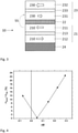
Fig. 3 , amagnetoresistive element 10 is shown comprising areference layer 21 having areference magnetization 210 and asense layer 23 having asense magnetization 230. Atunnel barrier layer 22 is included between thereference layer 21 and thesense layer 23. Thereference layer 21 comprises a reference SAF structure including afirst reference sublayer 211, asecond reference sublayer 212 in contact with thetunnel barrier layer 22 and a non-magneticreference spacer layer 213 between the first andsecond reference sublayers first reference sublayer 211 is antiferromagnetically coupled to thesecond reference sublayer 212. Thesense layer 23 comprises a sense SAF structure including afirst sense sublayer 231 in contact with thetunnel barrier layer 22 and separated from asecond sense sublayer 232 by a non-magnetic firstsense spacer layer 233 such that thefirst sense sublayer 231 is antiferromagnetically coupled to thesecond sense sublayer 232. - Preferably, the
sense magnetization 230 is saturated. - In an embodiment, the magnetic moment of the
first sense sublayer 231 is smaller than the magnetic moment of thesecond sense sublayer 232. More particularly, a sense magnetic ratio ΔM, i.e., the ratio of the magnetic moment of the first sense sublayer 231 to the magnetic moment of thesecond sense sublayer 232, can be defined by Equation (1):
first sense sublayer 231, tFM1 corresponds to the thickness of thefirst sense sublayer 231, MSFM2 corresponds to the spontaneous magnetization of thesecond sense sublayer 232 and tFM2 corresponds to the thickness of thesecond sense sublayer 232. - In a preferred embodiment, the sense magnetic ratio ΔM is between 0.1 and 0.25.
-
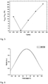
Fig. 4 reports the ratio of the SAF stray field HAFM to the FM stray field HFM as a function of the sense magnetic ratio ΔM. Here, the SAF stray field HAFM corresponds to thenet stray field 55 generated by thesense SAF structure 23, i.e., the stray field resulting from thedifferent sense sublayers sense layer 23 comprising a single ferromagnetic layer or several ferromagnetically coupled ferromagnetic layers. The SAF stray field HAFM was calculated for thefirst sense sublayer 231 having a thickness of 2 nm and for thesecond sense sublayer 232 having a thickness between 2 nm and 6 nm. The FM stray field HFM was calculated for a ferromagnetic layer having a thickness of between 0 nm and 4 nm.Fig. 4 shows that a sense magnetic ratio ΔM of 0.2 yields a ratio of the SAF stray field HAFM to the FM stray field HFM of 14%. -
Fig. 5 reports the ratio of the SAF stray field HAFM to the FM stray field HFM as a function of the thickness of thesecond sense sublayer 232. Thefirst sense sublayer 231 has a thickness of 2 nm. When the ratio of the SAF stray field HAFM to the FM stray field HFM is null, and when the sense magnetic ratio ΔM is null, thesense layer 23 loses its capability to sense the external magnetic field. This corresponds to thesecond sense sublayer 232 having a thickness of 3 nm in the example ofFig. 5 . - A sense magnetic ratio ΔM between 0.1 and 0.25 provides a good sensitivity of the
magnetoresistive element 10 to the external magnetic field. Moreover, it reduces the netstray field 55 on thereference layer 21 such that the response of themagnetoresistive element 10 to an angularly varying external magnetic field shows substantially no hysteresis.Fig. 6 shows the variation of a signal measured by the magnetoresistive element 10 (such as a resistance value) as a function of the angle of the external magnetic field being measured. Here, the netstray field 55 generated by thesense layer 23 has a magnitude of 400 Oe. Almost no hysteresis is observed. - The
magnetoresistive element 10 described herein can have lower magnetic noise and higher tunnel magnetoresistance (TMR) by using thick magnetic layers in thesensing layer 23. The reduction of the netstray field 55 generated by thesense layer 23 and acting on the pinnedreference layer 21 can further have enhanced stability to high temperature, improved life-time stability and improved overall performance. - As shown in
Figs. 4 and5 , the ratio of the magnetic moments in the first andsecond sense sublayers stray field 55 by selecting the thickness of the first andsecond sense sublayers second sense sublayers sense layer 23. - In one aspect, the first and
second sense sublayers second sense sublayers first sense sublayer 231 comprises nonmagnetic elements in order to dilute the ferromagnetic material constituting thefirst sense sublayer 231 and decrease itsspontaneous magnetization 230. - In another aspect, the
second sense sublayer 232 has a greater thickness than thefirst sense sublayer 231. - In one aspect, the first
sense spacer layer 233 can comprise a non-magnetic material such as, but not limited to, Ru, W, Mo or Ir or a combination of these elements. - With reference to
Fig. 7 , themagnetoresistive element 10 is shown according to another embodiment, wherein thefirst sense sublayer 231 is antiferromagnetically coupled to thesecond sense sublayer 232, and wherein thesecond sense sublayer 232 comprises a gradient of the sensespontaneous magnetization 230. More particularly the sensespontaneous magnetization 230 in thesecond sense sublayer 232 increases with increasing distance from the firstsense spacer layer 233. - The net
spontaneous magnetization 230 of thesecond sense sublayer 232 can be adjusted to compensate thespontaneous magnetization 230 of thefirst sense sublayer 231 such as to adjust the sense magnetic ratio ΔM, for example between 0.1 and 0.25. Here, MSFM2 corresponds to the net spontaneous magnetization of thesecond sense sublayer 232. - Since the magnitude of the
stray field 55 decreases as the cube of the distance, thelarger sense magnetization 230 in the portion of thesecond sense sublayer 232 farthest from thereference layer 21 does not contribute significantly to the netstray field 55 at the level of thereference layer 21. On the other hand, thelarger sense magnetization 230 allows for increasing the TMR of themagnetoresistive element 10. - has a sense
spontaneous magnetization 230 that is smaller, for example at least two times, than the sensespontaneous magnetization 230 of thefirst sense sublayer 231 and, thus, generate a smaller netstray field 55 on thereference layer 21. On the level of thereference layer 21, the netstray field 55 produced by thesecond sense sublayer 232 is smaller than the one produced by thefirst sense sublayer 231. - In one aspect, the
second sense sublayer 232 comprises a gradient of nonmagnetic impurities. More particularly, thesecond sense sublayer 232 comprises nonmagnetic impurities in a concentration that decreases with increasing distance from the firstsense spacer layer 233. The increasing content of nonmagnetic impurities dilutes the ferromagnetic material of thesecond sense sublayer 232 towards the firstsense spacer layer 233. -
Fig. 8 shows a detail of thesecond sense sublayer 232 according to another aspect. Here, thesecond sense sublayer 232 comprises a plurality of ferromagnetic sense bi-layers 232bl, wherein each sense bi-layer 232bl includes a lowspontaneous sense layer 237 and a highspontaneous sense layer 238. The highspontaneous sense layer 238 has a sensespontaneous magnetization 230 higher than the one of the lowspontaneous sense layer 237. The thicknesses of the lowspontaneous sense layer 237 relative to the thicknesses of the highspontaneous sense layer 238 decreases with increasing distance from the firstsense spacer layer 233. - Any one of, alone or in combination, the thickness of the
second sense sublayer 232, the gradient of the sensespontaneous magnetization 230 or the arrangement of the sense bi-layers 232bl, can be adjusted in order to obtain the ratio of the magnetic moment of thefirst sense sublayer 231 to the magnetic moment of thesecond sense sublayer 232 between 0.1 and 0.25, and to decrease the netstray field 55 applied on thereference layer 21. - The configuration of the
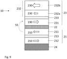
magnetoresistive element 10 shown inFigs. 7 and 8 allows for obtaining a lowstray field 55 and have a sense magnetic ratio ΔM between 0.1 and 0.25 using only a singlesense spacer layer 233. In the case thesecond sense sublayer 232 comprises a plurality of ferromagnetic sense bi-layers 232bl, the term MSFM2 corresponds to the net spontaneous magnetization of the plurality of ferromagnetic sense bi-layers 232bl and tFM2 corresponds to the thickness of thesecond sense sublayer 232 comprising the plurality of ferromagnetic sense bi-layers 232bl.Fig. 9 illustrates themagnetoresistive element 10 according to yet another embodiment, wherein thesecond sense sublayer 232 comprises a proximalsecond sense sublayer 232a and a distalsecond sense sublayer 232b. The distalsecond sense sublayer 232b has a sensespontaneous magnetization 230 that is at least two times higher than the sensespontaneous magnetization 230 of the proximalsecond sense sublayer 232a. The proximalsecond sense sublayer 232a is ferromagnetically coupled to the distalsecond sense sublayer 232b. - Here, the sense magnetic ratio ΔM does not depend on a specific arrangement of the first and second sense layers 231, 232a, 232b but rather on the net magnetic moment of these layers. More particularly, the term MSFM2 tFM2 in Equation (1) corresponds to MSFM2a tFM2a + MSFM2b tFM2b, where MSFM2a and tFM2a respectively correspond to the spontaneous magnetization and thickness of the proximal
second sense sublayer 232a and where MSFM2b and tFM2b, respectively correspond to the spontaneous magnetization and thickness of the distalsecond sense sublayer 232b. - In one aspect, the lower sense
spontaneous magnetization 230 of the proximalsecond sense sublayer 232a relative to the distalsecond sense sublayer 232b can be obtained by including nonmagnetic impurities in the ferromagnetic proximalsecond sense sublayer 232a such as to dilute the spontaneous magnetization of the ferromagnetic material. Alternatively or in combination, the relative lower sensespontaneous magnetization 230 of the proximalsecond sense sublayer 232a can be obtained by the distalsecond sense sublayer 232b having a greater thickness that the thickness of the proximalsecond sense sublayer 232a. - The sense
spontaneous magnetization 230 of the proximalsecond sense sublayer 232a can be adjusted to compensate the stray field generated by thefirst sense sublayer 231 and decrease the netstray field 55 at thereference layer 21. Since the magnitude of thestray field 55 decreases as the cube of the distance, the stray field generated by the thicker distalsecond sense sublayer 232b has a negligible contribution in the netstray field 55 at thereference layer 21. Thelarger sense magnetization 230 of the distalsecond sense sublayer 232b allows for increasing the TMR of themagnetoresistive element 10. -
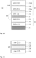
Fig. 10 illustrates a variant of themagnetoresistive element 10 shown inFig. 9 , wherein thesecond sense sublayer 232 comprises a proximalsecond sense sublayer 232a separated from a distalsecond sense sublayer 232b by a non-magnetic secondsense spacer layer 235. The secondsense spacer layer 235 can comprise a non-magnetic material such as, but not limited to, Ru, W, Mo or Ir or a combination of these elements. In this configuration, the distalsecond sense sublayer 232b is antiferromagnetically coupled to the proximalsecond sense sublayer 232a. - Similarly to the configuration of the
magnetoresistive element 10 shown inFig. 9 , the thickness of the proximalsecond sense sublayer 232a can be adjusted to compensate the stray field generated by thefirst sense sublayer 231 and decrease the netstray field 55 at thereference layer 21. The stray field generated by the thicker distalsecond sense sublayer 232b has a negligible contribution in the netstray field 55 at thereference layer 21. Thelarger sense magnetization 230 of the distalsecond sense sublayer 232b allows for increasing the TMR of themagnetoresistive element 10. - In a variant not illustrated, the sequence: "
first sense layer 231 / firstsense spacer layer 233 /second sense layer 232" can be repeated a plurality of times forming a multi-layered structure. Such multi-layered structure can have a spontaneous magnetization that is lower than the spontaneous magnetization of the distalsecond sense layer 232b. The multi-layered structure can be strongly coupled to the distalsecond sense layer 232b. - The thickness of the
first sense layer 231 and/or thesecond sense layer 232, as well as the thickness of the proximal and distal second sense layers 232a, 232b in themagnetoresistive element 10 according to the configuration ofFigs. 9 and10 , can be adjusted in order to decrease thestray field 55. -
Fig. 11 shows a detail of thesense layer 23 according to an embodiment, wherein thesense layer 23 further comprises an intermediateferromagnetic sense layer 236 on each side of the firstsense spacer layer 233 and in contact with the firstsense spacer layer 233. The intermediateferromagnetic sense layer 236 can be a nanolayer, for example have a thickness of about 1 nm. The intermediateferromagnetic sense layer 236 can comprises any one of a Co or CoFe -based alloy. Preferably, the intermediateferromagnetic sense layer 236 has a high spontaneous magnetization. For example, the intermediateferromagnetic sense layer 236 can comprises a CoFe alloy containing 25 to 50% wt Fe. - Improved sensing layer structure with two or more antiferromagnetically coupled sublayers. Proper choice of sense layer materials and sense layer thickness provides significant reduction of hysteresis in sensor angular response, improves sensitivity, signal to noise ratio and longevity of sensor lifetime.
- In an embodiment, a 2D magnetic sensor comprises a plurality of the
magnetoresistive element 10 disclosed herein. -
- 10
- magnetoresistive element
- 21
- reference layer, reference SAF structure
- 210
- reference magnetization
- 211
- first reference sublayer
- 212
- second reference sublayer
- 213
- reference spacer layer
- 22
- tunnel barrier layer
- 23
- sense layer, sense SAF structure
- 230
- sense magnetization
- 231
- first sense sublayer
- 232
- second sense sublayer
- 232a
- proximal second sense sublayer
- 232b
- distal second sense sublayer
- 232bl
- sense bi-layer
- 233
- first sense spacer layer
- 234
- third sense sublayer
- 235
- second sense spacer layer
- 236
- intermediate ferromagnetic sense layer
- 237
- low spontaneous sense layer
- 238
- high spontaneous sense layer
- 24
- pinning layer, antiferromagnetic layer
- 55
- local magnetic stray field, net stray field
- ΔM
- sense magnetic ratio
- HAFM
- SAF stray field
- HFM
- FM stray field
Claims (15)
- A magnetoresistive element (10) for a 2D magnetic sensor, the magnetoresistive element (10) comprising a tunnel barrier layer (22) included between a reference layer (21) having a reference magnetization (210) and a sense layer (23) having a sense magnetization (230);
wherein the sense layer (23) comprises a synthetic antiferromagnetic (SAF) structure including a ferromagnetic first sense sublayer (231) in contact with the tunnel barrier layer (22) and separated from a ferromagnetic second sense sublayer (232) by a first non-magnetic spacer layer (233) such that the first sense sublayer (231) is antiferromagnetically coupled to the second sense sublayer (232); and
wherein the sense layer (23) is configured such that a sense magnetic ratio (ΔM) defined as:
wherein MSFM1 and MSFM2 are the spontaneous magnetizations of, respectively, the first and second sense sublayers (231, 232) and tFM1 and tFM2 are the thicknesses of, respectively, the first and second sense sublayers (231, 232); and
wherein the sense magnetic ratio (ΔM) is between 0.1 and 0.25. - The magnetoresistive element according to claim 1,
wherein the first sense sublayer (231)has a thickness between 1 nm and 3 nm and the second sense sublayer (232) has a thickness between 2 nm and 6 nm. - The magnetoresistive element according to claim 2,
wherein the second sense sublayer (232) has a greater thickness than the first sense sublayer (231). - The magnetoresistive element according to claim 3,
wherein the first sense sublayer (231) comprises nonmagnetic elements in order to decrease its spontaneous magnetization (230). - The magnetoresistive element according to any one of claims 1 to 4,
wherein the sense spacer layer (233) comprises Ru, W, Mo or Ir or a combination of these elements. - The magnetoresistive element according to any one of claims 1 to 5,
wherein the second sense sublayer (232) comprises a spontaneous magnetization (230) that increases with increasing distance from the sense spacer layer (233). - The magnetoresistive element according to claim 6,
wherein the second sense sublayer (232) comprises a ferromagnetic material containing nonmagnetic impurities in a concentration that decreases with increasing distance from the sense spacer layer (233). - The magnetoresistive element according to claim 6,
wherein the second sense sublayer (232) comprises a plurality of ferromagnetic sense bi-layers (232bl), each sense bi-layer (232bl) including a low spontaneous sense layer (237) and a high spontaneous sense layer (238) having a spontaneous magnetization (230) higher than the one of the low spontaneous sense layer (237); and
wherein the thicknesses of the low spontaneous sense layer (237) relative to the thicknesses of the high spontaneous sense layer (238) decreases with increasing distance from the sense spacer layer (233). - The magnetoresistive element (10) according to any one of claims 1 to 5,
wherein the second sense sublayer (232) comprises a proximal second sense sublayer 232a and a distal second sense sublayer 232bferromagnetically coupled to the proximal second sense sublayer (232a); and
wherein the a distal second sense sublayer (232b) has a spontaneous magnetization (230) that is at least two times greater than the proximal second sense sublayer (232a). - The magnetoresistive element (10) according to claim 9,
wherein the proximal second sense sublayer (232a) comprises a ferromagnetic material containing nonmagnetic impurities decreasing the spontaneous magnetization (230) of the ferromagnetic material. - The magnetoresistive element (10) according to any one of claims 1 to 5,
wherein the second sense sublayer (232) comprises a proximal second sense sublayer (232a) separated from a distal second sense sublayer (232b) by a non-magnetic second sense spacer layer (235) and antiferromagnetically coupled to the distal second sense sublayer (232b). - The magnetoresistive element (10) according to claim 11,
wherein the spontaneous magnetization (230) of the distal second sense sublayer (232b) is higher than the spontaneous magnetization (230) of the first sense layer (231) and the proximal second sense sublayer (232a). - The magnetoresistive element (10) according to claim 11 or 12, comprising a plurality of the sense SAF structure (231, 232, 233).
- The magnetoresistive element (10) according to any one of claims 1 to 13,
wherein the sense layer (23) further comprises an intermediate ferromagnetic sense layer (236) on each side of the sense spacer layer (233) and in contact with the sense spacer layer(233). - 2D magnetic sensor comprising a plurality of the magnetoresistive element (10) according to any one of claims 1 to 14.
Priority Applications (5)
| Application Number | Priority Date | Filing Date | Title |
|---|---|---|---|
| EP20315414.1A EP3971598B1 (en) | 2020-09-18 | 2020-09-18 | Magnetoresistive element for a 2d magnetic sensor having a reduced hysteresis response |
| JP2023515805A JP7555484B2 (en) | 2020-09-18 | 2021-09-14 | Magnetoresistance element for two-dimensional magnetic sensor with reduced hysteresis response |
| PCT/IB2021/058336 WO2022058875A1 (en) | 2020-09-18 | 2021-09-14 | Magnetoresistive element for a 2d magnetic sensor having a reduced hysteresis response |
| US18/245,380 US12174276B2 (en) | 2020-09-18 | 2021-09-14 | Magnetoresistive element for a 2D magnetic sensor having a reduced hysteresis response |
| KR1020237009350A KR102808448B1 (en) | 2020-09-18 | 2021-09-14 | Magnetoresistive elements for two-dimensional magnetic sensors with reduced hysteresis response |
Applications Claiming Priority (1)
| Application Number | Priority Date | Filing Date | Title |
|---|---|---|---|
| EP20315414.1A EP3971598B1 (en) | 2020-09-18 | 2020-09-18 | Magnetoresistive element for a 2d magnetic sensor having a reduced hysteresis response |
Publications (2)
| Publication Number | Publication Date |
|---|---|
| EP3971598A1 true EP3971598A1 (en) | 2022-03-23 |
| EP3971598B1 EP3971598B1 (en) | 2025-09-03 |
Family
ID=72885483
Family Applications (1)
| Application Number | Title | Priority Date | Filing Date |
|---|---|---|---|
| EP20315414.1A Active EP3971598B1 (en) | 2020-09-18 | 2020-09-18 | Magnetoresistive element for a 2d magnetic sensor having a reduced hysteresis response |
Country Status (5)
| Country | Link |
|---|---|
| US (1) | US12174276B2 (en) |
| EP (1) | EP3971598B1 (en) |
| JP (1) | JP7555484B2 (en) |
| KR (1) | KR102808448B1 (en) |
| WO (1) | WO2022058875A1 (en) |
Cited By (1)
| Publication number | Priority date | Publication date | Assignee | Title |
|---|---|---|---|---|
| CN119148030A (en) * | 2024-11-18 | 2024-12-17 | 兰州大学 | Method for measuring magnetic microfilament circumferential alternating current loop based on LabVIEW |
Citations (4)
| Publication number | Priority date | Publication date | Assignee | Title |
|---|---|---|---|---|
| EP1727149A1 (en) * | 2005-05-19 | 2006-11-29 | NEC Corporation | Magnetoresistive device and magnetic memory using the same |
| US20090121710A1 (en) * | 2007-11-09 | 2009-05-14 | Headway Technologies, Inc. | Novel free layer design for TMR/CPP device |
| US20100316890A1 (en) * | 2007-10-26 | 2010-12-16 | Canon Anelva Corporation | Magnetic tunnel junction device with magnetic free layer having sandwich structure |
| US20170140781A1 (en) * | 2015-11-12 | 2017-05-18 | Seagate Technology Llc | Reader with free layer experiencing opposite phase-shifted media torques |
Family Cites Families (9)
| Publication number | Priority date | Publication date | Assignee | Title |
|---|---|---|---|---|
| JP3607850B2 (en) * | 2000-04-06 | 2005-01-05 | アルプス電気株式会社 | Magnetoresistive thin film magnetic element, method of manufacturing the same, and thin film magnetic head including the magnetoresistive thin film magnetic element |
| JP3706793B2 (en) * | 2000-06-20 | 2005-10-19 | アルプス電気株式会社 | Spin valve thin film magnetic element, method of manufacturing the same, and thin film magnetic head including the spin valve thin film magnetic element |
| JP3931876B2 (en) | 2002-11-01 | 2007-06-20 | 日本電気株式会社 | Magnetoresistive device and manufacturing method thereof |
| JP2006332527A (en) | 2005-05-30 | 2006-12-07 | Renesas Technology Corp | Magnetic memory element |
| WO2007015355A1 (en) | 2005-08-02 | 2007-02-08 | Nec Corporation | Mram |
| JP4594839B2 (en) | 2005-09-29 | 2010-12-08 | 株式会社東芝 | Magnetic random access memory, method for manufacturing magnetic random access memory, and data writing method for magnetic random access memory |
| US7800868B2 (en) * | 2005-12-16 | 2010-09-21 | Seagate Technology Llc | Magnetic sensing device including a sense enhancing layer |
| JP2008109118A (en) * | 2006-09-29 | 2008-05-08 | Toshiba Corp | Magnetoresistive element and magnetic random access memory using the same |
| SG11201604655PA (en) * | 2014-05-12 | 2016-07-28 | Fuji Electric Co Ltd | Method for manufacturing perpendicular magnetic recording medium |
-
2020
- 2020-09-18 EP EP20315414.1A patent/EP3971598B1/en active Active
-
2021
- 2021-09-14 KR KR1020237009350A patent/KR102808448B1/en active Active
- 2021-09-14 JP JP2023515805A patent/JP7555484B2/en active Active
- 2021-09-14 WO PCT/IB2021/058336 patent/WO2022058875A1/en not_active Ceased
- 2021-09-14 US US18/245,380 patent/US12174276B2/en active Active
Patent Citations (4)
| Publication number | Priority date | Publication date | Assignee | Title |
|---|---|---|---|---|
| EP1727149A1 (en) * | 2005-05-19 | 2006-11-29 | NEC Corporation | Magnetoresistive device and magnetic memory using the same |
| US20100316890A1 (en) * | 2007-10-26 | 2010-12-16 | Canon Anelva Corporation | Magnetic tunnel junction device with magnetic free layer having sandwich structure |
| US20090121710A1 (en) * | 2007-11-09 | 2009-05-14 | Headway Technologies, Inc. | Novel free layer design for TMR/CPP device |
| US20170140781A1 (en) * | 2015-11-12 | 2017-05-18 | Seagate Technology Llc | Reader with free layer experiencing opposite phase-shifted media torques |
Cited By (1)
| Publication number | Priority date | Publication date | Assignee | Title |
|---|---|---|---|---|
| CN119148030A (en) * | 2024-11-18 | 2024-12-17 | 兰州大学 | Method for measuring magnetic microfilament circumferential alternating current loop based on LabVIEW |
Also Published As
| Publication number | Publication date |
|---|---|
| KR20230069125A (en) | 2023-05-18 |
| JP7555484B2 (en) | 2024-09-24 |
| US20230296703A1 (en) | 2023-09-21 |
| US12174276B2 (en) | 2024-12-24 |
| WO2022058875A1 (en) | 2022-03-24 |
| JP2023545902A (en) | 2023-11-01 |
| KR102808448B1 (en) | 2025-05-16 |
| EP3971598B1 (en) | 2025-09-03 |
Similar Documents
| Publication | Publication Date | Title |
|---|---|---|
| US6988414B2 (en) | Sensor device having a magnetostrictive force sensor | |
| JP5124606B2 (en) | Magnetoresistive multilayer devices and sensor elements | |
| US20100255349A1 (en) | Magnetic sensing device including a sense enhancing layer | |
| JPH06181349A (en) | Magnetoresistive weak magnetic field sensor | |
| US12313707B2 (en) | Magnetoresistive sensor element having compensated temperature coefficient of sensitivity and method for manufacturing said element | |
| KR20230117352A (en) | Magnetoresistive element for sensing the magnetic field in the Z axis | |
| US6809909B2 (en) | Giant magnetoresistive sensor with high-resistivity magnetic layers | |
| US20010015878A1 (en) | Magnetic sensor and magnetic storage using same | |
| EP3971598B1 (en) | Magnetoresistive element for a 2d magnetic sensor having a reduced hysteresis response | |
| EP0560350B1 (en) | Magneto-resistance effect element | |
| RU2316783C2 (en) | Magneto-resistive layered system and sensitive element on basis of such a layered system | |
| JP2024511753A (en) | Magnetoresistive element and magnetic sensor device with high sensitivity and low zero magnetic field offset shift | |
| JP2023547034A (en) | Magnetoresistive sensor element with wide linear response and robust nominal performance and method for manufacturing the same | |
| US20240345182A1 (en) | Magnetoresistive element having compensated temperature coefficient of tmr | |
| US12287381B2 (en) | Magnetoresistive sensor element for sensing a two-dimensional magnetic field with low high-field error | |
| EP4198541A1 (en) | Magnetoresistive element having high out-of-plane sensitivity | |
| US20260029492A1 (en) | Tmr sensor with sensing multilayer structure | |
| US20260003017A1 (en) | Magnetoresistive element for sensing a magnetic field in an out-of-plane direction with increased sensitivity |
Legal Events
| Date | Code | Title | Description |
|---|---|---|---|
| PUAI | Public reference made under article 153(3) epc to a published international application that has entered the european phase |
Free format text: ORIGINAL CODE: 0009012 |
|
| STAA | Information on the status of an ep patent application or granted ep patent |
Free format text: STATUS: THE APPLICATION HAS BEEN PUBLISHED |
|
| AK | Designated contracting states |
Kind code of ref document: A1 Designated state(s): AL AT BE BG CH CY CZ DE DK EE ES FI FR GB GR HR HU IE IS IT LI LT LU LV MC MK MT NL NO PL PT RO RS SE SI SK SM TR |
|
| STAA | Information on the status of an ep patent application or granted ep patent |
Free format text: STATUS: REQUEST FOR EXAMINATION WAS MADE |
|
| 17P | Request for examination filed |
Effective date: 20220804 |
|
| RBV | Designated contracting states (corrected) |
Designated state(s): AL AT BE BG CH CY CZ DE DK EE ES FI FR GB GR HR HU IE IS IT LI LT LU LV MC MK MT NL NO PL PT RO RS SE SI SK SM TR |
|
| RAP3 | Party data changed (applicant data changed or rights of an application transferred) |
Owner name: CROCUS TECHNOLOGY SA |
|
| RAP1 | Party data changed (applicant data changed or rights of an application transferred) |
Owner name: ALLEGRO MICROSYSTEMS, LLC |
|
| RAP1 | Party data changed (applicant data changed or rights of an application transferred) |
Owner name: ALLEGRO MICROSYSTEMS, LLC |
|
| GRAP | Despatch of communication of intention to grant a patent |
Free format text: ORIGINAL CODE: EPIDOSNIGR1 |
|
| STAA | Information on the status of an ep patent application or granted ep patent |
Free format text: STATUS: GRANT OF PATENT IS INTENDED |
|
| RIC1 | Information provided on ipc code assigned before grant |
Ipc: G01R 33/00 20060101ALN20250217BHEP Ipc: H01F 10/32 20060101ALI20250217BHEP Ipc: G01R 33/09 20060101AFI20250217BHEP |
|
| GRAJ | Information related to disapproval of communication of intention to grant by the applicant or resumption of examination proceedings by the epo deleted |
Free format text: ORIGINAL CODE: EPIDOSDIGR1 |
|
| STAA | Information on the status of an ep patent application or granted ep patent |
Free format text: STATUS: REQUEST FOR EXAMINATION WAS MADE |
|
| INTG | Intention to grant announced |
Effective date: 20250305 |
|
| GRAP | Despatch of communication of intention to grant a patent |
Free format text: ORIGINAL CODE: EPIDOSNIGR1 |
|
| STAA | Information on the status of an ep patent application or granted ep patent |
Free format text: STATUS: GRANT OF PATENT IS INTENDED |
|
| INTC | Intention to grant announced (deleted) | ||
| INTG | Intention to grant announced |
Effective date: 20250424 |
|
| RIC1 | Information provided on ipc code assigned before grant |
Ipc: G01R 33/00 20060101ALN20250411BHEP Ipc: H01F 10/32 20060101ALI20250411BHEP Ipc: G01R 33/09 20060101AFI20250411BHEP |
|
| GRAS | Grant fee paid |
Free format text: ORIGINAL CODE: EPIDOSNIGR3 |
|
| GRAA | (expected) grant |
Free format text: ORIGINAL CODE: 0009210 |
|
| STAA | Information on the status of an ep patent application or granted ep patent |
Free format text: STATUS: THE PATENT HAS BEEN GRANTED |
|
| AK | Designated contracting states |
Kind code of ref document: B1 Designated state(s): AL AT BE BG CH CY CZ DE DK EE ES FI FR GB GR HR HU IE IS IT LI LT LU LV MC MK MT NL NO PL PT RO RS SE SI SK SM TR |
|
| REG | Reference to a national code |
Ref country code: CH Ref legal event code: EP |
|
| REG | Reference to a national code |
Ref country code: DE Ref legal event code: R096 Ref document number: 602020057916 Country of ref document: DE |
|
| REG | Reference to a national code |
Ref country code: IE Ref legal event code: FG4D |
|
| PGFP | Annual fee paid to national office [announced via postgrant information from national office to epo] |
Ref country code: DE Payment date: 20250916 Year of fee payment: 6 |
|
| REG | Reference to a national code |
Ref country code: NL Ref legal event code: MP Effective date: 20250903 |
|
| PG25 | Lapsed in a contracting state [announced via postgrant information from national office to epo] |
Ref country code: NO Free format text: LAPSE BECAUSE OF FAILURE TO SUBMIT A TRANSLATION OF THE DESCRIPTION OR TO PAY THE FEE WITHIN THE PRESCRIBED TIME-LIMIT Effective date: 20251203 |
|
| REG | Reference to a national code |
Ref country code: LT Ref legal event code: MG9D |
|
| PG25 | Lapsed in a contracting state [announced via postgrant information from national office to epo] |
Ref country code: FI Free format text: LAPSE BECAUSE OF FAILURE TO SUBMIT A TRANSLATION OF THE DESCRIPTION OR TO PAY THE FEE WITHIN THE PRESCRIBED TIME-LIMIT Effective date: 20250903 |
|
| PG25 | Lapsed in a contracting state [announced via postgrant information from national office to epo] |
Ref country code: HR Free format text: LAPSE BECAUSE OF FAILURE TO SUBMIT A TRANSLATION OF THE DESCRIPTION OR TO PAY THE FEE WITHIN THE PRESCRIBED TIME-LIMIT Effective date: 20250903 |
|
| PG25 | Lapsed in a contracting state [announced via postgrant information from national office to epo] |
Ref country code: GR Free format text: LAPSE BECAUSE OF FAILURE TO SUBMIT A TRANSLATION OF THE DESCRIPTION OR TO PAY THE FEE WITHIN THE PRESCRIBED TIME-LIMIT Effective date: 20251204 |
|
| PG25 | Lapsed in a contracting state [announced via postgrant information from national office to epo] |
Ref country code: SE Free format text: LAPSE BECAUSE OF FAILURE TO SUBMIT A TRANSLATION OF THE DESCRIPTION OR TO PAY THE FEE WITHIN THE PRESCRIBED TIME-LIMIT Effective date: 20250903 |
|
| PG25 | Lapsed in a contracting state [announced via postgrant information from national office to epo] |
Ref country code: LV Free format text: LAPSE BECAUSE OF FAILURE TO SUBMIT A TRANSLATION OF THE DESCRIPTION OR TO PAY THE FEE WITHIN THE PRESCRIBED TIME-LIMIT Effective date: 20250903 |
|
| PG25 | Lapsed in a contracting state [announced via postgrant information from national office to epo] |
Ref country code: PL Free format text: LAPSE BECAUSE OF FAILURE TO SUBMIT A TRANSLATION OF THE DESCRIPTION OR TO PAY THE FEE WITHIN THE PRESCRIBED TIME-LIMIT Effective date: 20250903 Ref country code: BG Free format text: LAPSE BECAUSE OF FAILURE TO SUBMIT A TRANSLATION OF THE DESCRIPTION OR TO PAY THE FEE WITHIN THE PRESCRIBED TIME-LIMIT Effective date: 20250903 |
|
| PG25 | Lapsed in a contracting state [announced via postgrant information from national office to epo] |
Ref country code: RS Free format text: LAPSE BECAUSE OF FAILURE TO SUBMIT A TRANSLATION OF THE DESCRIPTION OR TO PAY THE FEE WITHIN THE PRESCRIBED TIME-LIMIT Effective date: 20251203 |
|
| PG25 | Lapsed in a contracting state [announced via postgrant information from national office to epo] |
Ref country code: ES Free format text: LAPSE BECAUSE OF FAILURE TO SUBMIT A TRANSLATION OF THE DESCRIPTION OR TO PAY THE FEE WITHIN THE PRESCRIBED TIME-LIMIT Effective date: 20250903 |
|
| REG | Reference to a national code |
Ref country code: AT Ref legal event code: MK05 Ref document number: 1833651 Country of ref document: AT Kind code of ref document: T Effective date: 20250903 |
|
| PG25 | Lapsed in a contracting state [announced via postgrant information from national office to epo] |
Ref country code: NL Free format text: LAPSE BECAUSE OF FAILURE TO SUBMIT A TRANSLATION OF THE DESCRIPTION OR TO PAY THE FEE WITHIN THE PRESCRIBED TIME-LIMIT Effective date: 20250903 |
|
| PG25 | Lapsed in a contracting state [announced via postgrant information from national office to epo] |
Ref country code: SM Free format text: LAPSE BECAUSE OF FAILURE TO SUBMIT A TRANSLATION OF THE DESCRIPTION OR TO PAY THE FEE WITHIN THE PRESCRIBED TIME-LIMIT Effective date: 20250903 |
|
| PG25 | Lapsed in a contracting state [announced via postgrant information from national office to epo] |
Ref country code: AT Free format text: LAPSE BECAUSE OF FAILURE TO SUBMIT A TRANSLATION OF THE DESCRIPTION OR TO PAY THE FEE WITHIN THE PRESCRIBED TIME-LIMIT Effective date: 20250903 |
|
| PG25 | Lapsed in a contracting state [announced via postgrant information from national office to epo] |
Ref country code: RO Free format text: LAPSE BECAUSE OF FAILURE TO SUBMIT A TRANSLATION OF THE DESCRIPTION OR TO PAY THE FEE WITHIN THE PRESCRIBED TIME-LIMIT Effective date: 20250903 Ref country code: IT Free format text: LAPSE BECAUSE OF FAILURE TO SUBMIT A TRANSLATION OF THE DESCRIPTION OR TO PAY THE FEE WITHIN THE PRESCRIBED TIME-LIMIT Effective date: 20250903 |
|
| PG25 | Lapsed in a contracting state [announced via postgrant information from national office to epo] |
Ref country code: IS Free format text: LAPSE BECAUSE OF FAILURE TO SUBMIT A TRANSLATION OF THE DESCRIPTION OR TO PAY THE FEE WITHIN THE PRESCRIBED TIME-LIMIT Effective date: 20260103 |
|
| PG25 | Lapsed in a contracting state [announced via postgrant information from national office to epo] |
Ref country code: PT Free format text: LAPSE BECAUSE OF FAILURE TO SUBMIT A TRANSLATION OF THE DESCRIPTION OR TO PAY THE FEE WITHIN THE PRESCRIBED TIME-LIMIT Effective date: 20260105 Ref country code: CZ Free format text: LAPSE BECAUSE OF FAILURE TO SUBMIT A TRANSLATION OF THE DESCRIPTION OR TO PAY THE FEE WITHIN THE PRESCRIBED TIME-LIMIT Effective date: 20250903 |
|
| PG25 | Lapsed in a contracting state [announced via postgrant information from national office to epo] |
Ref country code: EE Free format text: LAPSE BECAUSE OF FAILURE TO SUBMIT A TRANSLATION OF THE DESCRIPTION OR TO PAY THE FEE WITHIN THE PRESCRIBED TIME-LIMIT Effective date: 20250903 Ref country code: SK Free format text: LAPSE BECAUSE OF FAILURE TO SUBMIT A TRANSLATION OF THE DESCRIPTION OR TO PAY THE FEE WITHIN THE PRESCRIBED TIME-LIMIT Effective date: 20250903 |
|
| REG | Reference to a national code |
Ref country code: CH Ref legal event code: H13 Free format text: ST27 STATUS EVENT CODE: U-0-0-H10-H13 (AS PROVIDED BY THE NATIONAL OFFICE) Effective date: 20260504 |
|
| PG25 | Lapsed in a contracting state [announced via postgrant information from national office to epo] |
Ref country code: LU Free format text: LAPSE BECAUSE OF NON-PAYMENT OF DUE FEES Effective date: 20250918 |
|
| REG | Reference to a national code |
Ref country code: BE Ref legal event code: MM Effective date: 20250930 |
|
| REG | Reference to a national code |
Ref country code: DE Ref legal event code: R097 Ref document number: 602020057916 Country of ref document: DE |
|
| PG25 | Lapsed in a contracting state [announced via postgrant information from national office to epo] |
Ref country code: LT Free format text: LAPSE BECAUSE OF FAILURE TO SUBMIT A TRANSLATION OF THE DESCRIPTION OR TO PAY THE FEE WITHIN THE PRESCRIBED TIME-LIMIT Effective date: 20250903 Ref country code: MC Free format text: LAPSE BECAUSE OF FAILURE TO SUBMIT A TRANSLATION OF THE DESCRIPTION OR TO PAY THE FEE WITHIN THE PRESCRIBED TIME-LIMIT Effective date: 20250903 |
|
| PG25 | Lapsed in a contracting state [announced via postgrant information from national office to epo] |
Ref country code: DK Free format text: LAPSE BECAUSE OF FAILURE TO SUBMIT A TRANSLATION OF THE DESCRIPTION OR TO PAY THE FEE WITHIN THE PRESCRIBED TIME-LIMIT Effective date: 20250903 |
|
| PLBE | No opposition filed within time limit |
Free format text: ORIGINAL CODE: 0009261 |
|
| STAA | Information on the status of an ep patent application or granted ep patent |
Free format text: STATUS: NO OPPOSITION FILED WITHIN TIME LIMIT |
|
| REG | Reference to a national code |
Ref country code: CH Ref legal event code: L10 Free format text: ST27 STATUS EVENT CODE: U-0-0-L10-L00 (AS PROVIDED BY THE NATIONAL OFFICE) Effective date: 20260715 |
|
| PG25 | Lapsed in a contracting state [announced via postgrant information from national office to epo] |
Ref country code: IE Free format text: LAPSE BECAUSE OF NON-PAYMENT OF DUE FEES Effective date: 20250918 Ref country code: CH Free format text: LAPSE BECAUSE OF NON-PAYMENT OF DUE FEES Effective date: 20250930 Ref country code: BE Free format text: LAPSE BECAUSE OF NON-PAYMENT OF DUE FEES Effective date: 20250930 |
|
| PG25 | Lapsed in a contracting state [announced via postgrant information from national office to epo] |
Ref country code: FR Free format text: LAPSE BECAUSE OF NON-PAYMENT OF DUE FEES Effective date: 20251103 |
|
| 26N | No opposition filed |
Effective date: 20260604 |