EP3971553A1 - Image processing method, image processing device, imaging system, and program - Google Patents
Image processing method, image processing device, imaging system, and program Download PDFInfo
- Publication number
- EP3971553A1 EP3971553A1 EP20812894.2A EP20812894A EP3971553A1 EP 3971553 A1 EP3971553 A1 EP 3971553A1 EP 20812894 A EP20812894 A EP 20812894A EP 3971553 A1 EP3971553 A1 EP 3971553A1
- Authority
- EP
- European Patent Office
- Prior art keywords
- characteristic data
- image
- ambient light
- image processing
- light component
- Prior art date
- Legal status (The legal status is an assumption and is not a legal conclusion. Google has not performed a legal analysis and makes no representation as to the accuracy of the status listed.)
- Granted
Links
Images





Classifications
-
- G—PHYSICS
- G01—MEASURING; TESTING
- G01N—INVESTIGATING OR ANALYSING MATERIALS BY DETERMINING THEIR CHEMICAL OR PHYSICAL PROPERTIES
- G01N21/00—Investigating or analysing materials by the use of optical means, i.e. using sub-millimetre waves, infrared, visible or ultraviolet light
- G01N21/17—Systems in which incident light is modified in accordance with the properties of the material investigated
- G01N21/25—Colour; Spectral properties, i.e. comparison of effect of material on the light at two or more different wavelengths or wavelength bands
-
- G—PHYSICS
- G01—MEASURING; TESTING
- G01N—INVESTIGATING OR ANALYSING MATERIALS BY DETERMINING THEIR CHEMICAL OR PHYSICAL PROPERTIES
- G01N21/00—Investigating or analysing materials by the use of optical means, i.e. using sub-millimetre waves, infrared, visible or ultraviolet light
- G01N21/17—Systems in which incident light is modified in accordance with the properties of the material investigated
- G01N21/55—Specular reflectivity
-
- G—PHYSICS
- G01—MEASURING; TESTING
- G01N—INVESTIGATING OR ANALYSING MATERIALS BY DETERMINING THEIR CHEMICAL OR PHYSICAL PROPERTIES
- G01N33/00—Investigating or analysing materials by specific methods not covered by groups G01N1/00 - G01N31/00
- G01N33/0098—Plants or trees
-
- G—PHYSICS
- G06—COMPUTING OR CALCULATING; COUNTING
- G06T—IMAGE DATA PROCESSING OR GENERATION, IN GENERAL
- G06T7/00—Image analysis
- G06T7/90—Determination of colour characteristics
-
- H—ELECTRICITY
- H04—ELECTRIC COMMUNICATION TECHNIQUE
- H04N—PICTORIAL COMMUNICATION, e.g. TELEVISION
- H04N23/00—Cameras or camera modules comprising electronic image sensors; Control thereof
- H04N23/70—Circuitry for compensating brightness variation in the scene
- H04N23/71—Circuitry for evaluating the brightness variation
-
- G—PHYSICS
- G01—MEASURING; TESTING
- G01N—INVESTIGATING OR ANALYSING MATERIALS BY DETERMINING THEIR CHEMICAL OR PHYSICAL PROPERTIES
- G01N21/00—Investigating or analysing materials by the use of optical means, i.e. using sub-millimetre waves, infrared, visible or ultraviolet light
- G01N21/84—Systems specially adapted for particular applications
- G01N2021/8466—Investigation of vegetal material, e.g. leaves, plants, fruits
-
- G—PHYSICS
- G01—MEASURING; TESTING
- G01N—INVESTIGATING OR ANALYSING MATERIALS BY DETERMINING THEIR CHEMICAL OR PHYSICAL PROPERTIES
- G01N2201/00—Features of devices classified in G01N21/00
- G01N2201/06—Illumination; Optics
- G01N2201/061—Sources
- G01N2201/0616—Ambient light is used
-
- G—PHYSICS
- G01—MEASURING; TESTING
- G01N—INVESTIGATING OR ANALYSING MATERIALS BY DETERMINING THEIR CHEMICAL OR PHYSICAL PROPERTIES
- G01N2201/00—Features of devices classified in G01N21/00
- G01N2201/12—Circuits of general importance; Signal processing
- G01N2201/124—Sensitivity
- G01N2201/1244—Ambient light detector, e.g. for invalidating
-
- G—PHYSICS
- G06—COMPUTING OR CALCULATING; COUNTING
- G06T—IMAGE DATA PROCESSING OR GENERATION, IN GENERAL
- G06T2207/00—Indexing scheme for image analysis or image enhancement
- G06T2207/10—Image acquisition modality
- G06T2207/10024—Color image
Definitions
- the present invention relates to an image processing method that estimates a concentration of a material included in an object from a spectral image.
- Patent Document 1 discloses a method of estimating a SPAD (Soil & Plant Analyzer Development) value from a spectral measurement result of light reflected by a plant.
- SPAD Soil & Plant Analyzer Development
- Patent Document 1 Japanese Patent Laid-Open No. 2002-168771
- the method disclosed in Patent Document 1 presumes that the light that has reached a light receiver is only the light reflected by the plant.
- the leaf of the plant is a semitransparent object and thus transmitting light transmitting through the leaf of the plant also reaches the light receiver as well as the reflected light reflected by the leaf of the plant.
- a mixture ratio of the reflected light and the transmitting light changes according to the weather (sunny, cloudy, etc.) and the position of the sun (altitude and azimuth). Therefore, the method disclosed in Patent Document 1 has difficulty in highly accurately estimate the concentration of the material (leaf color, that is, the SPAD value), because the mixture ratio of the reflected light and the transmitting light changes as the weather or the sun position changes.
- an object of the present invention to provide an image processing method, an image processing apparatus, an imaging system, and a program, each of which can highly accurately estimate a concentration of a material contained in an object from a spectral image.
- An image processing method includes an acquiring step of acquiring an image obtained by imaging of an object, ambient light data during the imaging, and reflection characteristic data and transmission characteristic data which depend on a concentration of a material contained in the object, and a separating step of separating a reflected light component and a transmitting light component in the image using the ambient light data, the reflection characteristic data, and the transmission characteristic data.
- An image processing apparatus includes an acquiring means of acquiring an image obtained by imaging of an object, ambient light data during the imaging, and reflection characteristic data and transmission characteristic data which depend on a concentration of a material contained in the object, and a separating means of separating a reflected light component and a transmitting light component in the image using the ambient light data, the reflection characteristic data, and the transmission characteristic data.
- An imaging system includes an image capturer configured to capture an object, a detector configured to detect ambient light data when the object is captured by the image capturer, and the image processing apparatus.
- a program according to another aspect of the present invention causes a computer to execute the image processing method.
- the present invention can provide an image processing method, an image processing apparatus, an imaging system, and a program, each of which can highly accurately estimate a concentration of a material contained in an object from a spectral image.
- FIG. 2 is an explanatory diagram of a camera captured model according to this embodiment.
- FIG. 2 illustrates an object 140 to be captured by a camera (image pickup apparatus) 200.
- the object 140 is illuminated by ambient light incident on the object 140 from each position on a hemispherical space in which the object 140 is placed.
- the ambient light is divided into ambient light 120 that illuminates the back surface of the object 140 and ambient light 130 that illuminates the front surface of the object 140.
- the object 140 is a semitransparent object, the ambient light 120 is diffused and absorbed inside the object 140, and part of transmitting light (transmitting light 121) reaches the camera 200.
- the ambient light 130 is diffused and absorbed inside the object 140, and part of the reflected light (reflected light 131) reaches the camera 200.
- the so-called diffuse reflected light reflected by such a process will be simply referred to as reflected light, and is distinguished from regular reflection light reflected on the surface of the object 140.
- the image of the object 140 captured by the camera 200 is formed by a mixture of transmitting light (transmitting light component) 121 and reflected light (reflected light component) 131 at a specific ratio.
- the mixture ratio of the transmitting light 121 and the reflected light 131 changes as the ambient lights 120 and 130 fluctuate.
- the mixture ratio of the transmitting light 121 and the reflected light 131 changes depending on the weather (sunny, cloudy, etc.) and the sun position (altitude and azimuth).
- This embodiment can quantitatively estimate the concentration of the material contained in the object by separating the transmitting light 121 and the reflected light 131 (separation processing) from the spectral image captured under such ambient light.
- separation processing will be described in detail.
- this embodiment formulates the camera captured model illustrated in FIG. 2 , for example, as in the expression (1).
- I n represents a luminance value of an image (spectral image) captured by the camera 200
- a subscript n represents a wavelength number of the spectral image.
- I R,n , and I T, n represent luminance values when the reflected light 131 and the transmitting light 121 are acquired independently.
- I R0, n and I T0,n represent the illuminances of the ambient lights 130 and 120 that illuminate the object 140, respectively.
- R n (c) and T n (c) represent spectral reflection characteristics (reflection characteristic data) and spectral transmission characteristics (transmission characteristic data), respectively, depending on the concentration c of the material contained in the object 140.
- each of the spectral reflection characteristic R n (c) and the spectral transmission characteristic T n (c) has previously been stored as known library data in a storage device such as a memory.
- k R represents a ratio of the ambient light 130 reflected by the object 140 and reaching the camera 200
- k T represents a ratio of the ambient light 120 passing through the object 140 and reaching the camera 200.
- the illuminance information I R0, n , and the illuminance information I T0,n of the ambient lights 130 and 120 during imaging are known and acquired, for example, by the ambient light information acquirer (detector) 110 illustrated in FIG. 2 .
- the ambient light information acquirer 110 includes an ambient light sensor (first ambient light sensor) 111 and an ambient light sensor (second ambient light sensor) 112 installed in two different directions.
- the ambient light sensor 111 acquires the illuminance information I T0,n of the ambient light 120.
- the ambient light sensor 112 acquires the illuminance information I R0, n of the ambient light 130.
- This embodiment acquires the ratio k R of the reflected light (reflected light component), the ratio k T of the transmitting light (transmitting light component), and the concentration c of the material contained in the object 140 by performing the optimization (optimization calculation) represented by the following expression (2) using the camera captured model formulated in this way.
- this embodiment can separate the transmitting light 121 and the reflected light 131 from the spectral image in which the transmitting light 121 and the reflected light 131 are mixed at an unknown mixture ratio. Further, this embodiment can quantitatively estimate the concentration of the material contained in the object 140.
- This embodiment relates to an image processing system (imaging system) that estimates the concentration of the object (paddy rice leaf) 140 from the image (spectral image) acquired by the camera (RGB camera) 200.
- concentration c in the expression (2) corresponds to the SPAD value.
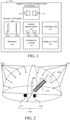
- FIG. 1 is a block diagram of the image processing system 100.
- the image processing system 100 includes an image capturer 101, an image processor (image processing apparatus) 102, a controller 103, a memory 104, a communicator 105, a display unit 106, and an ambient light information acquirer 110.
- the image capturer 101 includes an imaging optical system 101a and an image sensor 101b.
- the image sensor 101b photoelectrically converts an optical image (object image) formed via the imaging optical system 101a and outputs an image (image data) to the image processor 102.
- the image processor 102 has an acquiring means 102a and a separating means 102b.
- the image processing system 100 can be provided inside the camera 200.
- some functions such as the image processor 102 of the image processing system 100 may be implemented in a computer (user PC) away from the camera 200 or on cloud computing.
- the camera 200 has only part of the image processing system 100 including the image capturer 101.
- FIG. 2 illustrates the object 140 that is imaged under outdoor ambient light using the image processing system 100.
- the ambient light information acquirer 110 of the image processing system 100 includes an ambient light sensor 111 configured to acquire the illuminance incident on the back surface of the object 140, and an ambient light sensor 112 configured to acquire the illuminance incident on the front surface of the object 140.
- FIG. 3 is a flowchart of the image processing method according to this embodiment. Each step in FIG. 3 is mainly executed by the acquiring means 102a or the separating means 102b in the image processor 102.
- the image capturer 101 in the image processing system 100 images the object 140 by the signal from the controller 103 and acquires an RGB image (spectral image). Then, the acquiring means 102a in the image processor 102 acquires the image captured by the image capturer 101.
- the ambient light information acquirer 110 (ambient light sensors 111 and 112) acquires (detects), based on the signal from the controller 103, the ambient light information (ambient light data) I R0, n and I T0,n .
- the ambient light information is information on the tint.
- the acquiring means 102a acquires the ambient light information I R0, n and I T0,n detected by the ambient light information acquirer 110.
- the ambient light sensors 111 and 112 is made by disposing a diffuser on a sensor having the same spectral sensitivity characteristic as that of the image capturer 101, and acquire ambient light information having the same spectral wavelength as that of the image capturer 101.
- the ambient light sensors 111 and 112 may include a spectroradiometer, and acquire the ambient light information I R0, n and I T0,n using the following expressions (5) and (6) with an acquired spectral irradiance E( ⁇ ), a spectral transmittance characteristic E( ⁇ ) of the imaging optical system, and a spectral sensitivity characteristic Sn( ⁇ ) of the image sensor.
- E T ( ⁇ ) is the illuminance of the ambient light 120
- E R ( ⁇ ) is the illuminance of the ambient light 130
- ⁇ n, 1 and ⁇ n, 2 are the shortest wavelength and the longest wavelength, respectively, in the wavelength band in which the image sensor 101b having the spectral sensitivity characteristic S n ( ⁇ ) has sensitivity.
- FIG. 4 is a flowchart of the separation processing according to this embodiment. Each step in FIG. 4 is mainly executed by the separating means 102b in the image processor 102.
- the separating means 102b performs an optimization calculation based on the expression (2).
- the separating means 102b calculates the reflected light component and transmitting light component of the expressions (3) and (4).
- the separating means 102b utilizes the reflection characteristic data and the transmission characteristic data of the object that have been previously stored.
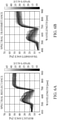
- FIG. 5 is an explanatory diagram of reflection characteristic data and transmission characteristic data.
- FIG. 5(a) is data showing SPAD value dependencies on the RGB reflectance and the RGB transmittance that have been acquired in advance.
- a dot plotted point represents the RGB reflectance
- a triangularly plotted point represents the RGB transmittance
- a filled color corresponds to the SPAD value.
- This embodiment separates, as illustrated in FIG. 5(a) , the reflected light and the transmitting light utilizing the fact that the spectral reflection characteristic and the spectral transmission characteristic have different characteristics from each other.
- FIG. 5(b) plots the results of fitting the RGB reflectance and RGB transmittance of FIG. 5(a) into the following expressions (7) and (8) by the least squares method using the SPAD value c as a parameter.
- a n, i and b n, i are constants determined by the least squares method.
- a dot plotted point represents the RGB reflectance
- a triangularly plotted point represents the RGB transmittance.
- This embodiment has stored information on the expressions (7) and (8) as the reflection characteristic data and the transmission characteristic data of the object, respectively.
- the reflection characteristic data and the transmission characteristic data are not limited to the above data.
- the reflectance characteristic Rfl(c, ⁇ ) and the transmittance characteristic Trs(c, ⁇ ) of the object may be used.
- FIG. 6 is an explanatory diagram of other reflection characteristic data and transmission characteristic data according to this embodiment.
- FIG. 6(a) illustrates a spectral reflectance characteristic of the paddy rice leaf, where the abscissa axis represents a wavelength and the ordinate axis represents a reflectance. The color of each line corresponds to the SPAD value shown on the color bar.
- FIG. 6(b) illustrates the transmittance characteristic of paddy rice, where the abscissa axis represents a wavelength and the ordinate axis illustrates a transmittance.
- R n (c) and T n (c) are preferably calculated using the following expressions (9) and (10) with the spectral transmittance characteristic L( ⁇ ) of the imaging optical system 101a and the spectral sensitivity characteristic Sn( ⁇ ) of the image sensor 101b.
- ⁇ n, 1 and ⁇ n, 2 are the shortest wavelength and the longest wavelength, respectively, in the wavelength band in which the image sensor 101b having the spectral sensitivity characteristic Sn( ⁇ ) has sensitivity.
- the separating means 102b performs the optimization calculation of the expression (2) using the spectral image, the ambient light information, and the reflection characteristic data and the transmission characteristic data of the object 140 stored in the memory 104.
- the optimization calculation can use a known optimization method, such as a gradient method.
- a known optimization method such as a gradient method.
- the expression (2) is also a differentiable function and thus a faster optimization calculation method such as the Newton method and the trust region method can be used.
- FIG. 7 is a diagram showing the result of the separation processing according to this embodiment and the result of performing the optimization calculation using a trust region method in the step S211 in FIG. 4 .
- FIG. 7(a) is an image made by converting an RGB image of paddy rice captured by an RGB camera into a grayscale image.
- FIGs. 7(b) to 7(d) are diagrams showing the results of optimizing calculations for the ratio k R of the reflected light, the ratio k T of the transmitting light, and the concentration c of the material for each pixel of the paddy rise leaf.
- FIG. 7(e) is a diagram showing a value f of the optimization evaluation function of the expression (2) on a logarithmic scale.
- the separating means 102b calculates the reflected light component and the transmitting light component based on the expressions (3), (4), (7), and (8) from the ratio k R of the reflected light, the ratio k T of the transmitting light, and the material concentration c obtained in the step S211.
- this embodiment can separate the reflected light component and the transmitting light component from the spectral image of the object.
- the material concentration c of the object 140 can be estimated.
- This embodiment estimates a SPAD value of a rice leaf from the spectral image acquired by the RGB camera in the same manner as in the first embodiment.
- FIGs. 8 and 9 a description will be given of a configuration of an image processing system 300 and the camera captured model according to this embodiment.
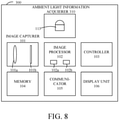
- FIG. 8 is a block diagram of the image processing system 300.
- FIG. 9 is an explanatory diagram of the camera captured model, and illustrates the object 140 that is captured under outdoor ambient light using the image processing system 300.
- the image processing system 300 according to this embodiment is different from the image processing system 100 according to the first embodiment having an ambient light information acquirer 110 in that the image processing system 300 includes an ambient light information acquirer (detector) 310. As illustrated in FIGs. 8 and 9 , the ambient light information acquirer 310 exclusively includes a single ambient light sensor 113. Since the other configuration of the image processing system 300 is the same as that of the image processing system 100, a description thereof will be omitted.
- FIG. 10 is an explanatory diagram of the ambient light information acquiring model in this embodiment, and illustrates the arrangement of the ambient light sensor 111 arranged westward and the ambient light sensor 112 arranged eastward.
- the ambient light sensors 111 and 112 have a configuration in which a diffuser plate is attached to an RGB color sensor.
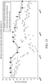
- FIG. 11 is an explanatory diagram of a time change of the ambient light information, and plots the ambient light information acquired by the ambient light sensors 111 and 112.
- WB R, b , WB R, r , WB T, b , and WB T, r are white balance correction coefficients calculated using the following expressions (11) to (14) with the illuminance information I R0, n acquired by the ambient light sensor 112 and the illuminance information I T0,n acquired by the ambient light sensor 111.
- n ⁇ 1, 2, 3 ⁇ , indicating that the values are acquired by the color sensors of R, G, and B in this order.
- FIG. 11(a) is a diagram that plots the time change of the white balance correction coefficient when it is cloudy.
- a black dot represents WB R,b
- a white dot represents WB T, b
- a black square represents WB R,r
- a white square represents WB T, r .
- WB R, b and WB T, b are equal to each other and WB R, r and WB T, r are equal to each other regardless of the arrangement orientation of the ambient light sensor.
- FIG. 11(b) is a diagram that plots the time change of the white balance correction coefficient when it is sunny in the same manner as in FIG. 11(a) . When it is sunny, WB R, b and WB T, b are equal to each other and WB R, r and WB T, r are equal to each other at only around midday when the sun crosses the meridian.
- this embodiment captures a spectral image when the white balance correction coefficient does not depend on the arrangement orientation of the ambient light sensor (such as within 2 hours before and after the sun crosses the meridian). Thereby, even the single ambient light sensor 113 can execute the separation processing of the reflected light and the transmitting light.
- the ambient light sensor 113 is installed upwardly, for example, as illustrated in FIG. 9 , and can acquire the ambient light information.
- I R0, n the ambient light information acquired by the ambient light sensor 113
- I T0,c m ⁇ I R0,c (m is a proportional constant)
- the expression (2) for the optimization calculation can be transformed as in the expression (15).
- k' T m ⁇ k T
- R n (c) and T n (c) use the data of the expressions (7) and (8).
- the method of acquiring the ambient light information I R0, n is not limited to the above method, and as illustrated in FIG. 12 , a standard reflective plate 114 is imaged by the camera 200, and the ambient light information IR 0 , n may be acquired from the pixel values of the image of the captured standard reflective plate.
- FIG. 12 is an explanatory diagram of a method of acquiring ambient light information using the standard reflective plate 114.
- FIG. 13 is a flowchart of the image processing method (SPAD value estimating method) according to this embodiment. Each step in FIG. 13 is mainly executed by the acquiring means 102a or the separating means 102b in the image processor 102.
- the image capturer 101 in the image processing system 300 images the object 140 in response to the signal from the controller 103 and acquires an RGB image (spectral image). Then, the acquiring means 102a in the image processor 102 acquires the image captured by the image capturer 101.
- the ambient light information acquirer 310 (ambient light sensor 113) acquires (detects) the ambient light information (ambient light data) I R0, n when the image is captured in response to the signal from the controller 103. Then, the acquiring means 102a acquires the ambient light information I R0, n detected by the ambient light information acquirer 310.
- the image processor 102 extracts the captured area (object area) of the paddy rice as the object 140.
- an image may be generated by converting an RGB image into an HSV color space, and pixels within a range of hue angles that can be taken by the paddy rice leaves may be extracted as the paddy rice area.
- the separating means 102b in the image processor 102 performs the separation processing.
- the separating means 102b performs an optimization calculation based on the expression (15) for each pixel of the paddy rice area extracted in the step S403.
- the separating means 102b calculates the reflected light component I' R, n whose ambient light component is corrected, using the following expression (16) with the ratio k R of the reflected light and the concentration c calculated in the step S404.
- the image processor 102 calculates NGRDI (Normalized Green Red Difference Index) as an index (growth index) that correlates with the SPAD value.
- NGRDI Normalized Green Red Difference Index
- NGRDI is calculated based on the following expression (17) using the reflected light component calculated in the step S405.
- the image processor 102 converts NGRDI into a SPAD value using the following expression (18), which is a correlation expression between NGRDI and the SPAD value.
- d i is a constant representing a correlation between NGRDI and the SPAD value.
- the material concentration c (corresponding to the SPAD value) is calculated by the optimization calculation of the expression (15), but the calculated material concentration c and the ratio k R of the reflected light contain errors. Therefore, this embodiment performs processes of the steps S405 to S407 in order to estimate the material concentration with more redundancy.
- the method according to this embodiment can improve the estimation accuracy of the SPAD value by using to estimate the SPAD value the optimization calculation result of only pixels having values f of the optimization evaluation function of the expression (15) are equal to or less than a threshold f th .
- FIG. 14 is an explanatory diagram of a difference in estimation accuracy of the SPAD value (material concentration) with respect to the threshold f th .
- the abscissa axis represents the threshold f th
- the ordinate axis represents the root mean square error RMSE between the average value and the correct value of the SPAD value estimation results of the pixels equal to or smaller than the threshold f th .
- the estimation accuracy of the SPAD value can be improved by properly setting the threshold f th .
- FIG. 15 is an explanatory diagram of the SPAD value estimation result, and illustrates the result of estimating the daily change of the SPAD value from the RGB image captured by a fixed-point camera.
- the abscissa axis represents the date and the ordinate axis represents the SPAD value.
- a squarely plotted point represents an estimation result when the separation processing according to this embodiment is not performed in the steps S404 and S405, and a dot plotted point represents an estimation result when the separation processing is performed.
- An asterisk plotted point represents a correct value, and an average value of the results measured by the SPAD meter is adopted as the correct value for 10 strains of paddy rice in the image estimation area.
- An error bar represents the standard deviation. Therefore, as illustrated in FIG. 15 , the separation processing according to this embodiment can quantitatively estimate the material concentration.
- the present invention can supply a program that implements one or more functions of the above embodiments to a system or apparatus via a network or a storage medium, and can be implemented by one or more processors in a computer of the system or apparatus configured to read and execute the program. It can also be implemented by a circuit ( e.g ., an ASIC) that implements one or more functions.
- a circuit e.g ., an ASIC
- the image processing apparatus has the acquiring means 102a and the separating means 102b.
- the acquiring means acquires the image of the object (spectral image), the ambient light data (information on the tint) when the object is imaged, and the reflection characteristic data (R n (c)) and transmission characteristic data (T n (c)) that depend on the concentration (SPAD value) of the material (chlorophyll, etc.) contained in the object.
- the separating means separates the reflected light component (I R, n ) and the transmitting light component (I T, n ) from the image using the image, the ambient light data, the reflection characteristic data, and the transmission characteristic data.
- each embodiment can separate the reflected light component and the transmitting light component from the spectral image obtained by imaging the semitransparent object. Therefore, each embodiment can provide an image processing method, an image processing apparatus, an imaging system, and a program, each of which can highly accurately estimate the concentration of a material contained in an object from a spectral image.
- a paddy rice leaf were taken as an example as an object, but it can also be applied to another object.
- the RGB spectral image is captured as an example, but each embodiment is also applicable to a multiband image and a hyperspectral image having four or more spectral wavelengths.
- the image capturer and the ambient light information acquirer are separated from each other, but the image capturer and the ambient light information acquirer may be integrated with each other.
- the evaluation function for the optimization is not limited to the expressions (2) and (15) and, for example, the L1 norm may be used instead of the L2 norm.
- Each embodiment illustratively executes the optimization calculation in the image processing apparatus, but the optimization calculation with heavy processing may be executed on the cloud computing.
Landscapes
- Engineering & Computer Science (AREA)
- Life Sciences & Earth Sciences (AREA)
- Physics & Mathematics (AREA)
- General Physics & Mathematics (AREA)
- Chemical & Material Sciences (AREA)
- Health & Medical Sciences (AREA)
- General Health & Medical Sciences (AREA)
- Immunology (AREA)
- Analytical Chemistry (AREA)
- Biochemistry (AREA)
- Pathology (AREA)
- Food Science & Technology (AREA)
- Botany (AREA)
- Wood Science & Technology (AREA)
- Medicinal Chemistry (AREA)
- Computer Vision & Pattern Recognition (AREA)
- Theoretical Computer Science (AREA)
- Multimedia (AREA)
- Signal Processing (AREA)
- Spectroscopy & Molecular Physics (AREA)
- Investigating Or Analysing Materials By Optical Means (AREA)
Abstract
Description
- The present invention relates to an image processing method that estimates a concentration of a material included in an object from a spectral image.
- There has recently proposed a method for estimating a leaf color index using the remote sensing technology for efficient and labor-saving agricultural work. For example,
Patent Document 1 discloses a method of estimating a SPAD (Soil & Plant Analyzer Development) value from a spectral measurement result of light reflected by a plant. - Patent Document 1:
Japanese Patent Laid-Open No. 2002-168771 - The method disclosed in
Patent Document 1 presumes that the light that has reached a light receiver is only the light reflected by the plant. However, the leaf of the plant is a semitransparent object and thus transmitting light transmitting through the leaf of the plant also reaches the light receiver as well as the reflected light reflected by the leaf of the plant. In addition, a mixture ratio of the reflected light and the transmitting light changes according to the weather (sunny, cloudy, etc.) and the position of the sun (altitude and azimuth). Therefore, the method disclosed inPatent Document 1 has difficulty in highly accurately estimate the concentration of the material (leaf color, that is, the SPAD value), because the mixture ratio of the reflected light and the transmitting light changes as the weather or the sun position changes. - Accordingly, it is an object of the present invention to provide an image processing method, an image processing apparatus, an imaging system, and a program, each of which can highly accurately estimate a concentration of a material contained in an object from a spectral image.
- An image processing method according to one aspect of the present invention includes an acquiring step of acquiring an image obtained by imaging of an object, ambient light data during the imaging, and reflection characteristic data and transmission characteristic data which depend on a concentration of a material contained in the object, and a separating step of separating a reflected light component and a transmitting light component in the image using the ambient light data, the reflection characteristic data, and the transmission characteristic data.
- An image processing apparatus according to another aspect of the present invention includes an acquiring means of acquiring an image obtained by imaging of an object, ambient light data during the imaging, and reflection characteristic data and transmission characteristic data which depend on a concentration of a material contained in the object, and a separating means of separating a reflected light component and a transmitting light component in the image using the ambient light data, the reflection characteristic data, and the transmission characteristic data.
- An imaging system according to another aspect of the present invention includes an image capturer configured to capture an object, a detector configured to detect ambient light data when the object is captured by the image capturer, and the image processing apparatus.
- A program according to another aspect of the present invention causes a computer to execute the image processing method.
- Other objects and features of the invention will be described in the following embodiments.
- The present invention can provide an image processing method, an image processing apparatus, an imaging system, and a program, each of which can highly accurately estimate a concentration of a material contained in an object from a spectral image.
-
-
FIG. 1 is a block diagram of an image processing system according to a first embodiment. -
FIG. 2 is an explanatory diagram of a camera captured model according to the first embodiment. -
FIG. 3 is a flowchart of an image processing method according to the first embodiment. -
FIG. 4 is a flowchart of separation processing according to the first embodiment. -
FIG. 5 is an explanatory diagram of reflection characteristic data and transmission characteristic data according to the first embodiment. -
FIG. 6 is an explanatory diagram of other reflection characteristic data and transmission characteristic data according to the first embodiment. -
FIG. 7 is a result of the separation processing according to the first embodiment. -
FIG. 8 is a block diagram of an image processing system according to a second embodiment. -
FIG. 9 is an explanatory diagram of a camera captured model according to the second embodiment. -
FIG. 10 is an explanatory diagram of a model for acquiring ambient light information according to the second embodiment. -
FIG. 11 is an explanatory diagram of a time change of the ambient light information according to the second embodiment. -
FIG. 12 is an explanatory diagram of a method of acquiring the ambient light information using a standard reflective plate according to the second embodiment. -
FIG. 13 is a flowchart of an image processing method according to the second embodiment. -
FIG. 14 is an explanatory diagram of a difference in estimation accuracy of a material concentration depending on a threshold according to the second embodiment. -
FIG. 15 is an explanatory diagram of a SPAD value estimation result according to the second embodiment. - Referring now to the accompanying drawings, a description will be given of embodiments according to the present invention. Corresponding elements in respective figures will be designated by the same reference numerals, and a duplicate description thereof will be omitted.
- Referring now to
FIG. 2 , a description will be given of a camera captured model according to a first embodiment of the present invention.FIG. 2 is an explanatory diagram of a camera captured model according to this embodiment.FIG. 2 illustrates anobject 140 to be captured by a camera (image pickup apparatus) 200. Theobject 140 is illuminated by ambient light incident on theobject 140 from each position on a hemispherical space in which theobject 140 is placed. InFIG. 2 , the ambient light is divided intoambient light 120 that illuminates the back surface of theobject 140 andambient light 130 that illuminates the front surface of theobject 140. - The
object 140 is a semitransparent object, theambient light 120 is diffused and absorbed inside theobject 140, and part of transmitting light (transmitting light 121) reaches thecamera 200. On the other hand, theambient light 130 is diffused and absorbed inside theobject 140, and part of the reflected light (reflected light 131) reaches thecamera 200. In this embodiment, the so-called diffuse reflected light reflected by such a process will be simply referred to as reflected light, and is distinguished from regular reflection light reflected on the surface of theobject 140. - Therefore, the image of the
object 140 captured by thecamera 200 is formed by a mixture of transmitting light (transmitting light component) 121 and reflected light (reflected light component) 131 at a specific ratio. The mixture ratio of the transmittinglight 121 and the reflectedlight 131 changes as theambient lights light 121 and thereflected light 131 changes depending on the weather (sunny, cloudy, etc.) and the sun position (altitude and azimuth). - When the image is captured under the outdoor ambient light in this way, the mixture ratio of the transmitting
light 121 and thereflected light 131 is unknown and changes depending on the illumination environment during imaging. Therefore, it is difficult to quantitatively estimate the concentration of the material (chlorophyll or the like) contained in the object from the image captured in such a state. This embodiment can quantitatively estimate the concentration of the material contained in the object by separating the transmittinglight 121 and the reflected light 131 (separation processing) from the spectral image captured under such ambient light. Hereinafter, the separation processing will be described in detail. - First, this embodiment formulates the camera captured model illustrated in
FIG. 2 , for example, as in the expression (1). - [Expression 1]

- In the expression (1), In represents a luminance value of an image (spectral image) captured by the
camera 200, and a subscript n represents a wavelength number of the spectral image. For example, when thecamera 200 is an RGB camera, n = {1, 2, 3}, and Ii, I2, and I3 each indicate RGB luminance values. IR,n, and IT, n represent luminance values when thereflected light 131 and thetransmitting light 121 are acquired independently. IR0, n and IT0,n represent the illuminances of theambient lights object 140, respectively. Rn(c) and Tn(c) represent spectral reflection characteristics (reflection characteristic data) and spectral transmission characteristics (transmission characteristic data), respectively, depending on the concentration c of the material contained in theobject 140. In this embodiment, each of the spectral reflection characteristic Rn(c) and the spectral transmission characteristic Tn(c) has previously been stored as known library data in a storage device such as a memory. kR represents a ratio of theambient light 130 reflected by theobject 140 and reaching thecamera 200, and kT represents a ratio of theambient light 120 passing through theobject 140 and reaching thecamera 200. - The illuminance information IR0, n, and the illuminance information IT0,n of the
ambient lights FIG. 2 . In this embodiment, the ambientlight information acquirer 110 includes an ambient light sensor (first ambient light sensor) 111 and an ambient light sensor (second ambient light sensor) 112 installed in two different directions. The ambientlight sensor 111 acquires the illuminance information IT0,n of theambient light 120. The ambientlight sensor 112 acquires the illuminance information IR0, n of theambient light 130. - This embodiment acquires the ratio kR of the reflected light (reflected light component), the ratio kT of the transmitting light (transmitting light component), and the concentration c of the material contained in the
object 140 by performing the optimization (optimization calculation) represented by the following expression (2) using the camera captured model formulated in this way. - [Expression 2]

- In this expression (2), "|| || 2" represents the L2 norm. The separation processing according to this embodiment means the execution of the optimization calculation of the expression (2), but the present invention is not limited to this example. With kR, kT, and c obtained by the optimization, the reflected light (reflected light component) and the transmitting light (transmitting light component) are separated and expressed as illustrated in the following expressions (3) and (4), respectively.
- [Expressions 3]


- Therefore, this embodiment can separate the transmitting
light 121 and the reflected light 131 from the spectral image in which the transmittinglight 121 and the reflected light 131 are mixed at an unknown mixture ratio. Further, this embodiment can quantitatively estimate the concentration of the material contained in theobject 140. - This embodiment relates to an image processing system (imaging system) that estimates the concentration of the object (paddy rice leaf) 140 from the image (spectral image) acquired by the camera (RGB camera) 200. In this embodiment, the concentration c in the expression (2) corresponds to the SPAD value.
- Referring now to
FIG. 1 , a description will be given of the configuration of theimage processing system 100 according to this embodiment.FIG. 1 is a block diagram of theimage processing system 100. Theimage processing system 100 includes animage capturer 101, an image processor (image processing apparatus) 102, acontroller 103, amemory 104, acommunicator 105, adisplay unit 106, and an ambientlight information acquirer 110. Theimage capturer 101 includes an imagingoptical system 101a and animage sensor 101b. Theimage sensor 101b photoelectrically converts an optical image (object image) formed via the imagingoptical system 101a and outputs an image (image data) to theimage processor 102. Theimage processor 102 has an acquiringmeans 102a and a separating means 102b. - The
image processing system 100 can be provided inside thecamera 200. Alternatively, some functions such as theimage processor 102 of theimage processing system 100 may be implemented in a computer (user PC) away from thecamera 200 or on cloud computing. In this case, thecamera 200 has only part of theimage processing system 100 including theimage capturer 101. -
FIG. 2 illustrates theobject 140 that is imaged under outdoor ambient light using theimage processing system 100. As illustrated inFIG. 2 , the ambientlight information acquirer 110 of theimage processing system 100 includes an ambientlight sensor 111 configured to acquire the illuminance incident on the back surface of theobject 140, and an ambientlight sensor 112 configured to acquire the illuminance incident on the front surface of theobject 140. - Referring now to
FIG. 3 , a description will be given of an image processing method according to this embodiment.FIG. 3 is a flowchart of the image processing method according to this embodiment. Each step inFIG. 3 is mainly executed by the acquiring means 102a or the separating means 102b in theimage processor 102. - First, in the step S201, the
image capturer 101 in theimage processing system 100 images theobject 140 by the signal from thecontroller 103 and acquires an RGB image (spectral image). Then, the acquiringmeans 102a in theimage processor 102 acquires the image captured by theimage capturer 101. At the same time as the step S201, in the step S202, the ambient light information acquirer 110 (ambientlight sensors 111 and 112) acquires (detects), based on the signal from thecontroller 103, the ambient light information (ambient light data) IR0, n and IT0,n. In this embodiment, the ambient light information is information on the tint. Then, the acquiringmeans 102a acquires the ambient light information IR0, n and IT0,n detected by the ambientlight information acquirer 110. - The ambient
light sensors image capturer 101, and acquire ambient light information having the same spectral wavelength as that of theimage capturer 101. The ambientlight sensors - [Expressions 4]


- In the expressions (5) and (6), ET(λ) is the illuminance of the
ambient light 120, ER(λ) is the illuminance of theambient light 130, and λn, 1 and λn, 2 are the shortest wavelength and the longest wavelength, respectively, in the wavelength band in which theimage sensor 101b having the spectral sensitivity characteristic Sn(λ) has sensitivity. - Next, in the step S210, the separating means 102b in the
image processor 102 performs separation processing based on the expression (2). Referring now toFIG. 4 , a description will be given of the separation processing according to this embodiment.FIG. 4 is a flowchart of the separation processing according to this embodiment. Each step inFIG. 4 is mainly executed by the separating means 102b in theimage processor 102. - First, in the step S211 the separating means 102b performs an optimization calculation based on the expression (2). Next, in the step S212, the separating means 102b calculates the reflected light component and transmitting light component of the expressions (3) and (4). In the steps S211 and S212, the separating means 102b utilizes the reflection characteristic data and the transmission characteristic data of the object that have been previously stored.
- Referring not to
FIG. 5 , a description will be given of the reflection characteristic data and the transmission characteristic data in this embodiment.FIG. 5 is an explanatory diagram of reflection characteristic data and transmission characteristic data.FIG. 5(a) is data showing SPAD value dependencies on the RGB reflectance and the RGB transmittance that have been acquired in advance. A dot plotted point represents the RGB reflectance, a triangularly plotted point represents the RGB transmittance, and a filled color corresponds to the SPAD value. This embodiment separates, as illustrated inFIG. 5(a) , the reflected light and the transmitting light utilizing the fact that the spectral reflection characteristic and the spectral transmission characteristic have different characteristics from each other. -
FIG. 5(b) plots the results of fitting the RGB reflectance and RGB transmittance ofFIG. 5(a) into the following expressions (7) and (8) by the least squares method using the SPAD value c as a parameter. - [Expressions 5]


- In expressions (7) and (8), an, i and bn, i are constants determined by the least squares method. In
FIG. 5(b) , similar toFIG. 5(a) , a dot plotted point represents the RGB reflectance, and a triangularly plotted point represents the RGB transmittance. - This embodiment has stored information on the expressions (7) and (8) as the reflection characteristic data and the transmission characteristic data of the object, respectively. The reflection characteristic data and the transmission characteristic data are not limited to the above data. For example, as illustrated in
FIG. 6 , the reflectance characteristic Rfl(c, λ) and the transmittance characteristic Trs(c, λ) of the object may be used.FIG. 6 is an explanatory diagram of other reflection characteristic data and transmission characteristic data according to this embodiment.FIG. 6(a) illustrates a spectral reflectance characteristic of the paddy rice leaf, where the abscissa axis represents a wavelength and the ordinate axis represents a reflectance. The color of each line corresponds to the SPAD value shown on the color bar. Similarly,FIG. 6(b) illustrates the transmittance characteristic of paddy rice, where the abscissa axis represents a wavelength and the ordinate axis illustrates a transmittance. - When the reflection characteristic data and the transmission characteristic data as illustrated in
FIG. 6 are used, Rn(c) and Tn(c) are preferably calculated using the following expressions (9) and (10) with the spectral transmittance characteristic L(λ) of the imagingoptical system 101a and the spectral sensitivity characteristic Sn(λ) of theimage sensor 101b. - [Expressions 6]


- In expressions (9) and (10), λn, 1 and λn, 2 are the shortest wavelength and the longest wavelength, respectively, in the wavelength band in which the
image sensor 101b having the spectral sensitivity characteristic Sn(λ) has sensitivity. - In the step S211 the separating means 102b performs the optimization calculation of the expression (2) using the spectral image, the ambient light information, and the reflection characteristic data and the transmission characteristic data of the
object 140 stored in thememory 104. The optimization calculation can use a known optimization method, such as a gradient method. As illustrated in the expressions (7) and (8), when Rn(c) and Tn(c) are differentiable functions, the expression (2) is also a differentiable function and thus a faster optimization calculation method such as the Newton method and the trust region method can be used. - Referring now to
FIG. 7 , a description will be given of the result of the separation processing by the optimization calculation.FIG. 7 is a diagram showing the result of the separation processing according to this embodiment and the result of performing the optimization calculation using a trust region method in the step S211 inFIG. 4 .FIG. 7(a) is an image made by converting an RGB image of paddy rice captured by an RGB camera into a grayscale image.FIGs. 7(b) to 7(d) are diagrams showing the results of optimizing calculations for the ratio kR of the reflected light, the ratio kT of the transmitting light, and the concentration c of the material for each pixel of the paddy rise leaf.FIG. 7(e) is a diagram showing a value f of the optimization evaluation function of the expression (2) on a logarithmic scale. - In the step S212 in
FIG. 4 , the separating means 102b calculates the reflected light component and the transmitting light component based on the expressions (3), (4), (7), and (8) from the ratio kR of the reflected light, the ratio kT of the transmitting light, and the material concentration c obtained in the step S211. As described above, this embodiment can separate the reflected light component and the transmitting light component from the spectral image of the object. In the processing of calculating the expression (2), the material concentration c of theobject 140 can be estimated. - Next follows a description of a second embodiment according to the present invention. This embodiment estimates a SPAD value of a rice leaf from the spectral image acquired by the RGB camera in the same manner as in the first embodiment.
- Referring now to
FIGs. 8 and9 , a description will be given of a configuration of animage processing system 300 and the camera captured model according to this embodiment. -
FIG. 8 is a block diagram of theimage processing system 300.FIG. 9 is an explanatory diagram of the camera captured model, and illustrates theobject 140 that is captured under outdoor ambient light using theimage processing system 300. Theimage processing system 300 according to this embodiment is different from theimage processing system 100 according to the first embodiment having an ambientlight information acquirer 110 in that theimage processing system 300 includes an ambient light information acquirer (detector) 310. As illustrated inFIGs. 8 and9 , the ambientlight information acquirer 310 exclusively includes a singleambient light sensor 113. Since the other configuration of theimage processing system 300 is the same as that of theimage processing system 100, a description thereof will be omitted. - Next follows a description of the reason for using only one
ambient light sensor 113 in this embodiment.FIG. 10 is an explanatory diagram of the ambient light information acquiring model in this embodiment, and illustrates the arrangement of the ambientlight sensor 111 arranged westward and the ambientlight sensor 112 arranged eastward. The ambientlight sensors -
FIG. 11 is an explanatory diagram of a time change of the ambient light information, and plots the ambient light information acquired by the ambientlight sensors FIG. 11 , WBR, b, WBR, r, WBT, b, and WBT, r are white balance correction coefficients calculated using the following expressions (11) to (14) with the illuminance information IR0, n acquired by the ambientlight sensor 112 and the illuminance information IT0,n acquired by the ambientlight sensor 111. n = {1, 2, 3}, indicating that the values are acquired by the color sensors of R, G, and B in this order. - [Expressions 7]


-
FIG. 11(a) is a diagram that plots the time change of the white balance correction coefficient when it is cloudy. A black dot represents WBR,b, a white dot represents WBT, b, a black square represents WBR,r, and a white square represents WBT, r. As illustrated inFIG. 11(a) , when it is cloudy, WBR, b and WBT, b are equal to each other and WBR, r and WBT, r are equal to each other regardless of the arrangement orientation of the ambient light sensor.FIG. 11(b) is a diagram that plots the time change of the white balance correction coefficient when it is sunny in the same manner as inFIG. 11(a) . When it is sunny, WBR, b and WBT, b are equal to each other and WBR, r and WBT, r are equal to each other at only around midday when the sun crosses the meridian. - Accordingly, this embodiment captures a spectral image when the white balance correction coefficient does not depend on the arrangement orientation of the ambient light sensor (such as within 2 hours before and after the sun crosses the meridian). Thereby, even the single
ambient light sensor 113 can execute the separation processing of the reflected light and the transmitting light. - At such a time (such as within 2 hours before and after the sun crosses the meridian), the white balance correction coefficient does not depend on the orientation of the ambient light sensor. Therefore, the ambient
light sensor 113 according to this embodiment is installed upwardly, for example, as illustrated inFIG. 9 , and can acquire the ambient light information. Where IR0, n is the ambient light information acquired by the ambientlight sensor 113 and IT0,c = m·IR0,c (m is a proportional constant), the expression (2) for the optimization calculation can be transformed as in the expression (15). - [Expression 8]

- In the expression (15), k'T = m·kT, and Rn(c) and Tn(c) use the data of the expressions (7) and (8). The method of acquiring the ambient light information IR0, n is not limited to the above method, and as illustrated in
FIG. 12 , a standardreflective plate 114 is imaged by thecamera 200, and the ambient light information IR0, n may be acquired from the pixel values of the image of the captured standard reflective plate.FIG. 12 is an explanatory diagram of a method of acquiring ambient light information using the standardreflective plate 114. - Referring now to
FIG. 13 , a description will be given of the image processing method according to this embodiment.FIG. 13 is a flowchart of the image processing method (SPAD value estimating method) according to this embodiment. Each step inFIG. 13 is mainly executed by the acquiring means 102a or the separating means 102b in theimage processor 102. - First, in the step S401, the
image capturer 101 in theimage processing system 300 images theobject 140 in response to the signal from thecontroller 103 and acquires an RGB image (spectral image). Then, the acquiringmeans 102a in theimage processor 102 acquires the image captured by theimage capturer 101. At the same time as the step S401, in the step S402, the ambient light information acquirer 310 (ambient light sensor 113) acquires (detects) the ambient light information (ambient light data) IR0, n when the image is captured in response to the signal from thecontroller 103. Then, the acquiringmeans 102a acquires the ambient light information IR0, n detected by the ambientlight information acquirer 310. - Next, in the step S403, the
image processor 102 extracts the captured area (object area) of the paddy rice as theobject 140. As a method for extracting the paddy rice area, for example, an image may be generated by converting an RGB image into an HSV color space, and pixels within a range of hue angles that can be taken by the paddy rice leaves may be extracted as the paddy rice area. - Next, in the steps S405 and S406, the separating means 102b in the
image processor 102 performs the separation processing. First, in the step S404, the separating means 102b performs an optimization calculation based on the expression (15) for each pixel of the paddy rice area extracted in the step S403. Next, in the step S405, the separating means 102b calculates the reflected light component I'R, n whose ambient light component is corrected, using the following expression (16) with the ratio kR of the reflected light and the concentration c calculated in the step S404. - [Expression 9]

- Next, in the step S406, the
image processor 102 calculates NGRDI (Normalized Green Red Difference Index) as an index (growth index) that correlates with the SPAD value. NGRDI is calculated based on the following expression (17) using the reflected light component calculated in the step S405. - [Expression 10]

- Finally, in the step S407, the
image processor 102 converts NGRDI into a SPAD value using the following expression (18), which is a correlation expression between NGRDI and the SPAD value. - [Expression 11]

- In the expression (18), di is a constant representing a correlation between NGRDI and the SPAD value.
- In the separation processing according to this embodiment, the material concentration c (corresponding to the SPAD value) is calculated by the optimization calculation of the expression (15), but the calculated material concentration c and the ratio kR of the reflected light contain errors. Therefore, this embodiment performs processes of the steps S405 to S407 in order to estimate the material concentration with more redundancy.
- The method according to this embodiment can improve the estimation accuracy of the SPAD value by using to estimate the SPAD value the optimization calculation result of only pixels having values f of the optimization evaluation function of the expression (15) are equal to or less than a threshold fth.
FIG. 14 is an explanatory diagram of a difference in estimation accuracy of the SPAD value (material concentration) with respect to the threshold fth. InFIG. 14 , the abscissa axis represents the threshold fth, and the ordinate axis represents the root mean square error RMSE between the average value and the correct value of the SPAD value estimation results of the pixels equal to or smaller than the threshold fth. As illustrated inFIG. 14 , the estimation accuracy of the SPAD value can be improved by properly setting the threshold fth. -
FIG. 15 is an explanatory diagram of the SPAD value estimation result, and illustrates the result of estimating the daily change of the SPAD value from the RGB image captured by a fixed-point camera. InFIG. 15 , the abscissa axis represents the date and the ordinate axis represents the SPAD value. InFIG. 15 , a squarely plotted point represents an estimation result when the separation processing according to this embodiment is not performed in the steps S404 and S405, and a dot plotted point represents an estimation result when the separation processing is performed. An asterisk plotted point represents a correct value, and an average value of the results measured by the SPAD meter is adopted as the correct value for 10 strains of paddy rice in the image estimation area. An error bar represents the standard deviation. Therefore, as illustrated inFIG. 15 , the separation processing according to this embodiment can quantitatively estimate the material concentration. - The present invention can supply a program that implements one or more functions of the above embodiments to a system or apparatus via a network or a storage medium, and can be implemented by one or more processors in a computer of the system or apparatus configured to read and execute the program. It can also be implemented by a circuit (e.g., an ASIC) that implements one or more functions.
- Thus, in each embodiment, the image processing apparatus (image processor 102) has the acquiring means 102a and the separating means 102b. The acquiring means acquires the image of the object (spectral image), the ambient light data (information on the tint) when the object is imaged, and the reflection characteristic data (Rn(c)) and transmission characteristic data (Tn(c)) that depend on the concentration (SPAD value) of the material (chlorophyll, etc.) contained in the object. The separating means separates the reflected light component (IR, n) and the transmitting light component (IT, n) from the image using the image, the ambient light data, the reflection characteristic data, and the transmission characteristic data. Thereby, the image processing apparatus according to each embodiment can separate the reflected light component and the transmitting light component from the spectral image obtained by imaging the semitransparent object. Therefore, each embodiment can provide an image processing method, an image processing apparatus, an imaging system, and a program, each of which can highly accurately estimate the concentration of a material contained in an object from a spectral image.
- Although preferable embodiments of the present invention have been described above, the present invention is not limited to these embodiments, and various modifications and changes can be made within the scope of the gist thereof.
- In particular, in each embodiment, a paddy rice leaf were taken as an example as an object, but it can also be applied to another object. In each embodiment, the RGB spectral image is captured as an example, but each embodiment is also applicable to a multiband image and a hyperspectral image having four or more spectral wavelengths. In each embodiment, the image capturer and the ambient light information acquirer are separated from each other, but the image capturer and the ambient light information acquirer may be integrated with each other. The evaluation function for the optimization is not limited to the expressions (2) and (15) and, for example, the L1 norm may be used instead of the L2 norm. Each embodiment illustratively executes the optimization calculation in the image processing apparatus, but the optimization calculation with heavy processing may be executed on the cloud computing.
Claims (19)
- An image processing method comprising:an acquiring step of acquiring an image obtained by imaging of an object, ambient light data during the imaging, and reflection characteristic data and transmission characteristic data which depend on a concentration of a material contained in the object; anda separating step of separating a reflected light component and a transmitting light component in the image using the ambient light data, the reflection characteristic data, and the transmission characteristic data.
- The image processing method according to claim 1, wherein the separating step includes an optimizing step for acquiring, through optimization, a ratio of the reflected light component and a ratio of the transmitting light component to a luminance value of the image.
- The image processing method according to claim 2, wherein the ambient light data includes first illuminance information acquired by a first ambient light sensor and second illuminance information acquired by a second ambient light sensor, and
wherein the optimizing step performs the optimization using the following expression:

- The image processing method according to claim 2, wherein the ambient light data is illuminance information acquired by an ambient light sensor, and
wherein the optimizing step performs the optimization using the following expression:
[Expression 2]
- The image processing method according to any one of claims 2 to 4, wherein the separating step includes a step of calculating at least one of the reflected light component or the transmitting light component using the ratio of the reflected light component, the ratio of the transmitting light, and the concentration of the material.
- The image processing method according to any one of claims 1 to 5, wherein the reflection characteristic data and the transmission characteristic data are a function of the concentration of the material.
- The image processing method according to claim 6, wherein the reflection characteristic data and the transmission characteristic data are differentiable with respect to the concentration of the material.
- The image processing method according to any one of claims 1 to 7, wherein the object is a leaf of a plant and the material is chlorophyll.
- An image processing apparatus comprising:an acquiring means of acquiring an image obtained by imaging of an object, ambient light data during the imaging, and reflection characteristic data and transmission characteristic data which depend on a concentration of a material contained in the object; anda separating means of separating a reflected light component and a transmitting light component in the image using the ambient light data, the reflection characteristic data, and the transmission characteristic data.
- The image processing apparatus according to claim 9, wherein the separating means acquires, through optimization, a ratio of the reflected light component and a ratio of the transmitting light component to a luminance value of the image.
- The image processing apparatus according to claim 10, wherein the ambient light data includes first illuminance information acquired by a first ambient light sensor and second illuminance information acquired by a second ambient light sensor, and
wherein the separating means performs the optimization using the following expression:
[Expression 3]
- The image processing apparatus according to claim 10, wherein the ambient light data is illuminance information acquired by an ambient light sensor, and
wherein the separating means performs the optimization using the following expression:
[Expression 4]
- The image processing apparatus according to any one of claims 10 to 12, wherein the separating means includes a step of calculating at least one of the reflected light component or the transmitting light component using the ratio of the reflected light component, the ratio of the transmitting light, and the concentration of the material.
- The image processing apparatus according to any one of claims 9 to 13, wherein the reflection characteristic data and the transmission characteristic data are a function of the concentration of the material.
- The image processing apparatus according to claim 14, wherein the reflection characteristic data and the transmission characteristic data are differentiable with respect to the concentration of the material.
- The image processing apparatus according to any one of claims 9 to 15, wherein the object is a leaf of a plant and the material is chlorophyll.
- An imaging system comprising:an image capturer configured to capture an object;a detector configured to detect ambient light data when the object is captured by the image capturer; andthe image processing apparatus according to any one of claims 9 to 15.
- The imaging system according to claim 17, wherein the detector exclusively includes a single ambient light sensor, and
wherein the ambient light data has illuminance information detected by the single ambient light sensor. - A program that causes a computer to execute the image processing method according to any one of claims 1 to 8.
Applications Claiming Priority (2)
| Application Number | Priority Date | Filing Date | Title |
|---|---|---|---|
| JP2019099129A JP7313906B2 (en) | 2019-05-28 | 2019-05-28 | IMAGE PROCESSING METHOD, IMAGE PROCESSING APPARATUS, IMAGING SYSTEM AND PROGRAM |
| PCT/JP2020/016789 WO2020241111A1 (en) | 2019-05-28 | 2020-04-16 | Image processing method, image processing device, imaging system, and program |
Publications (3)
| Publication Number | Publication Date |
|---|---|
| EP3971553A1 true EP3971553A1 (en) | 2022-03-23 |
| EP3971553A4 EP3971553A4 (en) | 2023-01-18 |
| EP3971553B1 EP3971553B1 (en) | 2024-11-13 |
Family
ID=73548647
Family Applications (1)
| Application Number | Title | Priority Date | Filing Date |
|---|---|---|---|
| EP20812894.2A Active EP3971553B1 (en) | 2019-05-28 | 2020-04-16 | Image processing method, image processing device, imaging system, and program |
Country Status (5)
| Country | Link |
|---|---|
| US (1) | US12135284B2 (en) |
| EP (1) | EP3971553B1 (en) |
| JP (1) | JP7313906B2 (en) |
| CN (1) | CN113874710B (en) |
| WO (1) | WO2020241111A1 (en) |
Families Citing this family (2)
| Publication number | Priority date | Publication date | Assignee | Title |
|---|---|---|---|---|
| US20250113107A1 (en) * | 2023-09-29 | 2025-04-03 | Apple Inc. | Automatic Continuous Flash Lighting for Close Range Image Capture |
| CN118154827B (en) * | 2024-03-13 | 2024-11-05 | 中国人民解放军战略支援部队航天工程大学 | Method for synthesizing weak light target spectrum data based on reflection spectrum calculation |
Family Cites Families (13)
| Publication number | Priority date | Publication date | Assignee | Title |
|---|---|---|---|---|
| JP3353561B2 (en) * | 1995-09-07 | 2002-12-03 | 株式会社日立製作所 | Method and apparatus for solution mass spectrometry |
| US6114683A (en) * | 1998-03-02 | 2000-09-05 | The United States Of Ameria As Represented By The Administrator Of The National Aeronautics And Space Administration | Plant chlorophyll content imager with reference detection signals |
| ID26384A (en) * | 1999-06-17 | 2000-12-21 | Satake Eng Co Ltd | DIAGNOSIS METHOD OF NUTRITIONAL CONDITIONS FROM HARVEST IN FLOOR PLANT |
| JP4243014B2 (en) * | 2000-12-01 | 2009-03-25 | 株式会社荏原製作所 | Plant growth measuring device |
| JP2004301810A (en) * | 2003-04-01 | 2004-10-28 | Ebara Corp | Plant growth degree measuring device |
| US7746452B2 (en) * | 2005-11-21 | 2010-06-29 | State Of Oregon Acting By And Through The State Board Of Higher Education On Behalf Of Oregon State University | Portable meter to measure chlorophyll, nitrogen and water and methods |
| JP5794149B2 (en) * | 2010-02-01 | 2015-10-14 | コニカミノルタ株式会社 | Color density measurement system |
| CN106954385B (en) * | 2015-01-09 | 2020-07-28 | 麦克赛尔控股株式会社 | Plant information acquisition system, plant information acquisition device, and plant information acquisition method |
| JP6489857B2 (en) | 2015-02-06 | 2019-03-27 | キヤノン株式会社 | Optical system and optical equipment |
| KR102109245B1 (en) * | 2015-05-12 | 2020-05-11 | 코니카 미놀타 가부시키가이샤 | Plant growth index measurement device and method, and plant growth index measurement system |
| US20180018537A1 (en) * | 2016-07-07 | 2018-01-18 | Purdue Research Foundation | Non-spectroscopic imaging of plants |
| JP2018151832A (en) * | 2017-03-13 | 2018-09-27 | キヤノン株式会社 | Information processing apparatus, information processing method, and program |
| CN110537197A (en) * | 2017-03-28 | 2019-12-03 | 柯尼卡美能达株式会社 | Image processing apparatus, maturation history image creation system and program |
-
2019
- 2019-05-28 JP JP2019099129A patent/JP7313906B2/en active Active
-
2020
- 2020-04-16 CN CN202080038049.XA patent/CN113874710B/en active Active
- 2020-04-16 WO PCT/JP2020/016789 patent/WO2020241111A1/en not_active Ceased
- 2020-04-16 EP EP20812894.2A patent/EP3971553B1/en active Active
-
2021
- 2021-11-22 US US17/532,206 patent/US12135284B2/en active Active
Also Published As
| Publication number | Publication date |
|---|---|
| JP7313906B2 (en) | 2023-07-25 |
| US20220082499A1 (en) | 2022-03-17 |
| CN113874710A (en) | 2021-12-31 |
| CN113874710B (en) | 2024-03-12 |
| JP2020193856A (en) | 2020-12-03 |
| WO2020241111A1 (en) | 2020-12-03 |
| US12135284B2 (en) | 2024-11-05 |
| EP3971553B1 (en) | 2024-11-13 |
| EP3971553A4 (en) | 2023-01-18 |
Similar Documents
| Publication | Publication Date | Title |
|---|---|---|
| Akkaynak et al. | Sea-thru: A method for removing water from underwater images | |
| CN113358224B (en) | A spectral reflectance detection method and system | |
| Tao et al. | Smartphone-based detection of leaf color levels in rice plants | |
| US8073279B2 (en) | Automated atmospheric characterization of remotely sensed multi-spectral imagery | |
| Berra et al. | Estimation of the spectral sensitivity functions of un-modified and modified commercial off-the-shelf digital cameras to enable their use as a multispectral imaging system for UAVs | |
| US7936377B2 (en) | Method and system for optimizing an image for improved analysis of material and illumination image features | |
| US11047793B2 (en) | Signal processing apparatus, signal processing method, and progress | |
| US20220366668A1 (en) | Image processing apparatus, image processing method, and image processing program | |
| CN111413279B (en) | Video processing method and device for multispectral detection and multispectral detection terminal | |
| US11422026B2 (en) | Information processing device, information processing method, and program to perform calibration with respect to environment light | |
| US9270866B2 (en) | Apparatus and method for automated self-training of white balance by electronic cameras | |
| US12135284B2 (en) | Image processing method, image processing apparatus, imaging system, and storage medium, for content concentration estimation | |
| US20240044785A1 (en) | Systems and methods for spectral analysis of plants | |
| US20220215509A1 (en) | Physics-based recovery of lost colors in underwater and atmospheric images under wavelength dependent absorption and scattering | |
| Toivonen et al. | Across-path DN gradient in Landsat TM imagery of Amazonian forests: A challenge for image interpretation and mosaicking | |
| JP2018151832A (en) | Information processing apparatus, information processing method, and program | |
| US12375781B2 (en) | Information processing apparatus, imaging system, and information processing method | |
| US10768097B2 (en) | Analyzer, image capturing apparatus that acquires color information, analyzing method, and storage medium | |
| JP4378810B2 (en) | Colorimetric conversion coefficient calculation method, colorimetric imaging method, colorimetric conversion coefficient calculation device, colorimetric imaging device, and computer-readable information recording medium recording a colorimetric conversion program | |
| US10489894B2 (en) | Image processing device, image processing method, and program recording medium | |
| Javoršek et al. | Comparison of two digital cameras based on spectral data estimation obtained with two methods | |
| JP2026054042A (en) | Image processing method, image processing device, image processing system, and program | |
| da Silva Souza et al. | A Low-Cost RGB-Based Image Processing Method for High-Throughput Assessment of Rice Grain Chalkiness | |
| CN119888464A (en) | Method, device, equipment and medium for detecting abnormal pixels of spectrum water quality inversion image | |
| CN114022476A (en) | Rice quality detection method |
Legal Events
| Date | Code | Title | Description |
|---|---|---|---|
| STAA | Information on the status of an ep patent application or granted ep patent |
Free format text: STATUS: THE INTERNATIONAL PUBLICATION HAS BEEN MADE |
|
| PUAI | Public reference made under article 153(3) epc to a published international application that has entered the european phase |
Free format text: ORIGINAL CODE: 0009012 |
|
| STAA | Information on the status of an ep patent application or granted ep patent |
Free format text: STATUS: REQUEST FOR EXAMINATION WAS MADE |
|
| 17P | Request for examination filed |
Effective date: 20211216 |
|
| AK | Designated contracting states |
Kind code of ref document: A1 Designated state(s): AL AT BE BG CH CY CZ DE DK EE ES FI FR GB GR HR HU IE IS IT LI LT LU LV MC MK MT NL NO PL PT RO RS SE SI SK SM TR |
|
| DAV | Request for validation of the european patent (deleted) | ||
| DAX | Request for extension of the european patent (deleted) | ||
| A4 | Supplementary search report drawn up and despatched |
Effective date: 20221221 |
|
| RIC1 | Information provided on ipc code assigned before grant |
Ipc: G01N 21/84 20060101ALN20221215BHEP Ipc: G06T 1/00 20060101ALI20221215BHEP Ipc: G01N 21/27 20060101ALI20221215BHEP Ipc: G01N 21/25 20060101AFI20221215BHEP |
|
| REG | Reference to a national code |
Ref legal event code: R079 Ipc: G01N0021250000 Ref country code: DE Ref document number: 602020041403 Country of ref document: DE Free format text: PREVIOUS MAIN CLASS: G01N0021270000 |
|
| GRAP | Despatch of communication of intention to grant a patent |
Free format text: ORIGINAL CODE: EPIDOSNIGR1 |
|
| STAA | Information on the status of an ep patent application or granted ep patent |
Free format text: STATUS: GRANT OF PATENT IS INTENDED |
|
| RIC1 | Information provided on ipc code assigned before grant |
Ipc: G01N 21/84 20060101ALN20240531BHEP Ipc: G01N 21/25 20060101AFI20240531BHEP |
|
| INTG | Intention to grant announced |
Effective date: 20240617 |
|
| GRAS | Grant fee paid |
Free format text: ORIGINAL CODE: EPIDOSNIGR3 |
|
| GRAA | (expected) grant |
Free format text: ORIGINAL CODE: 0009210 |
|
| STAA | Information on the status of an ep patent application or granted ep patent |
Free format text: STATUS: THE PATENT HAS BEEN GRANTED |
|
| AK | Designated contracting states |
Kind code of ref document: B1 Designated state(s): AL AT BE BG CH CY CZ DE DK EE ES FI FR GB GR HR HU IE IS IT LI LT LU LV MC MK MT NL NO PL PT RO RS SE SI SK SM TR |
|
| REG | Reference to a national code |
Ref country code: GB Ref legal event code: FG4D |
|
| REG | Reference to a national code |
Ref country code: CH Ref legal event code: EP |
|
| REG | Reference to a national code |
Ref country code: DE Ref legal event code: R096 Ref document number: 602020041403 Country of ref document: DE |
|
| REG | Reference to a national code |
Ref country code: IE Ref legal event code: FG4D |
|
| REG | Reference to a national code |
Ref country code: LT Ref legal event code: MG9D |
|
| REG | Reference to a national code |
Ref country code: NL Ref legal event code: MP Effective date: 20241113 |
|
| PG25 | Lapsed in a contracting state [announced via postgrant information from national office to epo] |
Ref country code: PT Free format text: LAPSE BECAUSE OF FAILURE TO SUBMIT A TRANSLATION OF THE DESCRIPTION OR TO PAY THE FEE WITHIN THE PRESCRIBED TIME-LIMIT Effective date: 20250313 Ref country code: HR Free format text: LAPSE BECAUSE OF FAILURE TO SUBMIT A TRANSLATION OF THE DESCRIPTION OR TO PAY THE FEE WITHIN THE PRESCRIBED TIME-LIMIT Effective date: 20241113 Ref country code: IS Free format text: LAPSE BECAUSE OF FAILURE TO SUBMIT A TRANSLATION OF THE DESCRIPTION OR TO PAY THE FEE WITHIN THE PRESCRIBED TIME-LIMIT Effective date: 20250313 |
|
| PG25 | Lapsed in a contracting state [announced via postgrant information from national office to epo] |
Ref country code: FI Free format text: LAPSE BECAUSE OF FAILURE TO SUBMIT A TRANSLATION OF THE DESCRIPTION OR TO PAY THE FEE WITHIN THE PRESCRIBED TIME-LIMIT Effective date: 20241113 Ref country code: NL Free format text: LAPSE BECAUSE OF FAILURE TO SUBMIT A TRANSLATION OF THE DESCRIPTION OR TO PAY THE FEE WITHIN THE PRESCRIBED TIME-LIMIT Effective date: 20241113 |
|
| REG | Reference to a national code |
Ref country code: AT Ref legal event code: MK05 Ref document number: 1742014 Country of ref document: AT Kind code of ref document: T Effective date: 20241113 |
|
| PG25 | Lapsed in a contracting state [announced via postgrant information from national office to epo] |
Ref country code: BG Free format text: LAPSE BECAUSE OF FAILURE TO SUBMIT A TRANSLATION OF THE DESCRIPTION OR TO PAY THE FEE WITHIN THE PRESCRIBED TIME-LIMIT Effective date: 20241113 |
|
| PG25 | Lapsed in a contracting state [announced via postgrant information from national office to epo] |
Ref country code: ES Free format text: LAPSE BECAUSE OF FAILURE TO SUBMIT A TRANSLATION OF THE DESCRIPTION OR TO PAY THE FEE WITHIN THE PRESCRIBED TIME-LIMIT Effective date: 20241113 |
|
| PG25 | Lapsed in a contracting state [announced via postgrant information from national office to epo] |
Ref country code: NO Free format text: LAPSE BECAUSE OF FAILURE TO SUBMIT A TRANSLATION OF THE DESCRIPTION OR TO PAY THE FEE WITHIN THE PRESCRIBED TIME-LIMIT Effective date: 20250213 |
|
| PG25 | Lapsed in a contracting state [announced via postgrant information from national office to epo] |
Ref country code: LV Free format text: LAPSE BECAUSE OF FAILURE TO SUBMIT A TRANSLATION OF THE DESCRIPTION OR TO PAY THE FEE WITHIN THE PRESCRIBED TIME-LIMIT Effective date: 20241113 Ref country code: AT Free format text: LAPSE BECAUSE OF FAILURE TO SUBMIT A TRANSLATION OF THE DESCRIPTION OR TO PAY THE FEE WITHIN THE PRESCRIBED TIME-LIMIT Effective date: 20241113 Ref country code: GR Free format text: LAPSE BECAUSE OF FAILURE TO SUBMIT A TRANSLATION OF THE DESCRIPTION OR TO PAY THE FEE WITHIN THE PRESCRIBED TIME-LIMIT Effective date: 20250214 |
|
| PG25 | Lapsed in a contracting state [announced via postgrant information from national office to epo] |
Ref country code: PL Free format text: LAPSE BECAUSE OF FAILURE TO SUBMIT A TRANSLATION OF THE DESCRIPTION OR TO PAY THE FEE WITHIN THE PRESCRIBED TIME-LIMIT Effective date: 20241113 |
|
| PG25 | Lapsed in a contracting state [announced via postgrant information from national office to epo] |
Ref country code: RS Free format text: LAPSE BECAUSE OF FAILURE TO SUBMIT A TRANSLATION OF THE DESCRIPTION OR TO PAY THE FEE WITHIN THE PRESCRIBED TIME-LIMIT Effective date: 20250213 |
|
| PG25 | Lapsed in a contracting state [announced via postgrant information from national office to epo] |
Ref country code: SM Free format text: LAPSE BECAUSE OF FAILURE TO SUBMIT A TRANSLATION OF THE DESCRIPTION OR TO PAY THE FEE WITHIN THE PRESCRIBED TIME-LIMIT Effective date: 20241113 |
|
| PGFP | Annual fee paid to national office [announced via postgrant information from national office to epo] |
Ref country code: DE Payment date: 20250319 Year of fee payment: 6 |
|
| PG25 | Lapsed in a contracting state [announced via postgrant information from national office to epo] |
Ref country code: DK Free format text: LAPSE BECAUSE OF FAILURE TO SUBMIT A TRANSLATION OF THE DESCRIPTION OR TO PAY THE FEE WITHIN THE PRESCRIBED TIME-LIMIT Effective date: 20241113 |
|
| PG25 | Lapsed in a contracting state [announced via postgrant information from national office to epo] |
Ref country code: EE Free format text: LAPSE BECAUSE OF FAILURE TO SUBMIT A TRANSLATION OF THE DESCRIPTION OR TO PAY THE FEE WITHIN THE PRESCRIBED TIME-LIMIT Effective date: 20241113 |
|
| PG25 | Lapsed in a contracting state [announced via postgrant information from national office to epo] |
Ref country code: RO Free format text: LAPSE BECAUSE OF FAILURE TO SUBMIT A TRANSLATION OF THE DESCRIPTION OR TO PAY THE FEE WITHIN THE PRESCRIBED TIME-LIMIT Effective date: 20241113 |
|
| PG25 | Lapsed in a contracting state [announced via postgrant information from national office to epo] |
Ref country code: SK Free format text: LAPSE BECAUSE OF FAILURE TO SUBMIT A TRANSLATION OF THE DESCRIPTION OR TO PAY THE FEE WITHIN THE PRESCRIBED TIME-LIMIT Effective date: 20241113 |
|
| PG25 | Lapsed in a contracting state [announced via postgrant information from national office to epo] |
Ref country code: CZ Free format text: LAPSE BECAUSE OF FAILURE TO SUBMIT A TRANSLATION OF THE DESCRIPTION OR TO PAY THE FEE WITHIN THE PRESCRIBED TIME-LIMIT Effective date: 20241113 |
|
| PG25 | Lapsed in a contracting state [announced via postgrant information from national office to epo] |
Ref country code: IT Free format text: LAPSE BECAUSE OF FAILURE TO SUBMIT A TRANSLATION OF THE DESCRIPTION OR TO PAY THE FEE WITHIN THE PRESCRIBED TIME-LIMIT Effective date: 20241113 |
|
| REG | Reference to a national code |
Ref country code: DE Ref legal event code: R097 Ref document number: 602020041403 Country of ref document: DE |
|
| PG25 | Lapsed in a contracting state [announced via postgrant information from national office to epo] |
Ref country code: SE Free format text: LAPSE BECAUSE OF FAILURE TO SUBMIT A TRANSLATION OF THE DESCRIPTION OR TO PAY THE FEE WITHIN THE PRESCRIBED TIME-LIMIT Effective date: 20241113 |
|
| PLBE | No opposition filed within time limit |
Free format text: ORIGINAL CODE: 0009261 |
|
| STAA | Information on the status of an ep patent application or granted ep patent |
Free format text: STATUS: NO OPPOSITION FILED WITHIN TIME LIMIT |
|
| 26N | No opposition filed |
Effective date: 20250814 |
|
| REG | Reference to a national code |
Ref country code: CH Ref legal event code: H13 Free format text: ST27 STATUS EVENT CODE: U-0-0-H10-H13 (AS PROVIDED BY THE NATIONAL OFFICE) Effective date: 20251125 |
|
| PG25 | Lapsed in a contracting state [announced via postgrant information from national office to epo] |
Ref country code: LU Free format text: LAPSE BECAUSE OF NON-PAYMENT OF DUE FEES Effective date: 20250416 |
|
| PG25 | Lapsed in a contracting state [announced via postgrant information from national office to epo] |
Ref country code: MC Free format text: LAPSE BECAUSE OF FAILURE TO SUBMIT A TRANSLATION OF THE DESCRIPTION OR TO PAY THE FEE WITHIN THE PRESCRIBED TIME-LIMIT Effective date: 20241113 |
|
| GBPC | Gb: european patent ceased through non-payment of renewal fee |
Effective date: 20250416 |
|
| REG | Reference to a national code |
Ref country code: BE Ref legal event code: MM Effective date: 20250430 |
|
| PG25 | Lapsed in a contracting state [announced via postgrant information from national office to epo] |
Ref country code: GB Free format text: LAPSE BECAUSE OF NON-PAYMENT OF DUE FEES Effective date: 20250416 |
|
| PG25 | Lapsed in a contracting state [announced via postgrant information from national office to epo] |
Ref country code: FR Free format text: LAPSE BECAUSE OF NON-PAYMENT OF DUE FEES Effective date: 20250430 |
|
| PG25 | Lapsed in a contracting state [announced via postgrant information from national office to epo] |
Ref country code: BE Free format text: LAPSE BECAUSE OF NON-PAYMENT OF DUE FEES Effective date: 20250430 |
|
| PG25 | Lapsed in a contracting state [announced via postgrant information from national office to epo] |
Ref country code: CH Free format text: LAPSE BECAUSE OF NON-PAYMENT OF DUE FEES Effective date: 20250430 |
|
| PG25 | Lapsed in a contracting state [announced via postgrant information from national office to epo] |
Ref country code: IE Free format text: LAPSE BECAUSE OF NON-PAYMENT OF DUE FEES Effective date: 20250416 |