EP3971546A1 - Load cell - Google Patents
Load cell Download PDFInfo
- Publication number
- EP3971546A1 EP3971546A1 EP21173551.9A EP21173551A EP3971546A1 EP 3971546 A1 EP3971546 A1 EP 3971546A1 EP 21173551 A EP21173551 A EP 21173551A EP 3971546 A1 EP3971546 A1 EP 3971546A1
- Authority
- EP
- European Patent Office
- Prior art keywords
- main body
- end portion
- load cell
- force
- deformation region
- Prior art date
- Legal status (The legal status is an assumption and is not a legal conclusion. Google has not performed a legal analysis and makes no representation as to the accuracy of the status listed.)
- Granted
Links
Images






Classifications
-
- G—PHYSICS
- G01—MEASURING; TESTING
- G01G—WEIGHING
- G01G23/00—Auxiliary devices for weighing apparatus
- G01G23/005—Means for preventing overload
-
- B—PERFORMING OPERATIONS; TRANSPORTING
- B29—WORKING OF PLASTICS; WORKING OF SUBSTANCES IN A PLASTIC STATE IN GENERAL
- B29C—SHAPING OR JOINING OF PLASTICS; SHAPING OF MATERIAL IN A PLASTIC STATE, NOT OTHERWISE PROVIDED FOR; AFTER-TREATMENT OF THE SHAPED PRODUCTS, e.g. REPAIRING
- B29C45/00—Injection moulding, i.e. forcing the required volume of moulding material through a nozzle into a closed mould; Apparatus therefor
- B29C45/17—Component parts, details or accessories; Auxiliary operations
- B29C45/76—Measuring, controlling or regulating
-
- G—PHYSICS
- G01—MEASURING; TESTING
- G01L—MEASURING FORCE, STRESS, TORQUE, WORK, MECHANICAL POWER, MECHANICAL EFFICIENCY, OR FLUID PRESSURE
- G01L1/00—Measuring force or stress, in general
- G01L1/20—Measuring force or stress, in general by measuring variations in ohmic resistance of solid materials or of electrically-conductive fluids; by making use of electrokinetic cells, i.e. liquid-containing cells wherein an electrical potential is produced or varied upon the application of stress
- G01L1/22—Measuring force or stress, in general by measuring variations in ohmic resistance of solid materials or of electrically-conductive fluids; by making use of electrokinetic cells, i.e. liquid-containing cells wherein an electrical potential is produced or varied upon the application of stress using resistance strain gauges
- G01L1/2206—Special supports with preselected places to mount the resistance strain gauges; Mounting of supports
- G01L1/2231—Special supports with preselected places to mount the resistance strain gauges; Mounting of supports the supports being disc- or ring-shaped, adapted for measuring a force along a single direction
-
- G—PHYSICS
- G01—MEASURING; TESTING
- G01L—MEASURING FORCE, STRESS, TORQUE, WORK, MECHANICAL POWER, MECHANICAL EFFICIENCY, OR FLUID PRESSURE
- G01L5/00—Apparatus for, or methods of, measuring force, work, mechanical power, or torque, specially adapted for specific purposes
- G01L5/16—Apparatus for, or methods of, measuring force, work, mechanical power, or torque, specially adapted for specific purposes for measuring several components of force
- G01L5/161—Apparatus for, or methods of, measuring force, work, mechanical power, or torque, specially adapted for specific purposes for measuring several components of force using variations in ohmic resistance
- G01L5/1627—Apparatus for, or methods of, measuring force, work, mechanical power, or torque, specially adapted for specific purposes for measuring several components of force using variations in ohmic resistance of strain gauges
Definitions
- the deformation region and the at least one strain gauge are arranged along a second direction, and the second direction is different from the first direction.
- the first end portion is a stressed end located at a top surface of the first main body, and the second end portion is a mounted end located at a bottom surface of the second main body.
- each of the first main body, the second main body and the connection portion is formed in a ring shape.
- the first end portion is a stressed end located at a top surface of the first main body, and the second end portion is a mounted end located at a bottom surface of the second main body.
- the gap includes a spaced distance, and the spaced distance is inversely proportional to the force, wherein when the spaced distance is reduced to zero, the force is greater than the specific range, and the elastic element is supported by the limitation element to limit deformation of the deformation region.
- a load cell in accordance with another aspect of the present disclosure, includes a first main body, a second main body, a connection portion, at least one strain gauge and a limitation element.
- the first main body includes a first end portion.
- the second main body includes a second end portion.
- the connection portion is connected between the first main body and the second main body and includes a deformation region.
- the first end portion and the second end portion are arranged along an axial direction.
- the at least one strain gauge is disposed in the deformation region. When a force is exerted on the first end portion in a first direction, the deformation region is deformed to drive the at least one strain gauge to change shape, so that the force is measured and standardized under a specific range.
- the limitation element is connected to the second main body. A gap is formed between the limitation element and the first main body.
- the first end portion is a stressed end located at a top surface of the first main body
- the second end portion is a mounted end located at a bottom surface of the second main body, and the gap is located between the first end portion and the second end portion.
- each of the first main body 11, the second main body 12 and the connection portion 13 is formed in a ring shape, and the first main body 11, the connection portion 13 and the second main body 12 are sequentially disposed along a radial direction.
- the first main body 11, the second main body 12 and the connection portion 13 are configured to form a first end portion 11a, a second end portion 12b and a deformation region 13a, respectively.
- the first end portion 11a is a stressed end located at a top surface of the first main body 11, and the second end portion 12b is a mounted end located at a bottom surface of the second main body 12.
- the deformation region 13a is located between the first end portion 11a and the second end portion 12b.
- the at least one strain gauge 20 is disposed in the deformation region 13a.
- the deformation region 13a and the at least one strain gauge 20 are extended along a second direction such as the radial direction.
- the second direction such as the radial direction is parallel to the XY plane and different from the axial direction (i.e., the Z-axis direction).
- the limitation element 30 is connected to the elastic element 10.
- a gap G is formed between the limitation element 30 and the elastic element 10 in the axial direction.
- the at least one strain gauge 20 is illustrated by four strain gauges S1 to S4.
- the four strain gauges S1 to S4 are secured on the top surface and the bottom surface of the connection portion 13, respectively.
- the strain gauge S1 and the strain gauge S4 are two strain gauges spatially corresponding to each other, and are symmetrically disposed on the top surface and the bottom surface of the connection portion 13, respectively.
- the strain gauge S2 and the strain gauge S3 are two strain gauges spatially corresponding to each other, and are symmetrically disposed on the top surface and the bottom surface of the connection portion 13, respectively.
- the elastic element 10 of the load cell 1a is made of aluminum, alloy steel, or stainless steel.
- each strain gauge S1 to S4 is constructed by a wire or a foil, which is set up in a zigzag pattern and attached to the connection portion 13.
- the four strain gauges S1 to S4 are set in a bridge circuit as shown in FIG. 2 .
- a change in its electrical resistances R1 to R4 occurs.
- the resulting alteration to the electrical resistances R1 to R4 in the strain gauges S1 to S4 can be measured as voltage V.
- the change in voltage V is proportional to the amount of the force F1 exerted on the load cell 1, thus the amount of force can be calculated from the output of load cell 1.
- the connection portion 13 in the deformation region 13a is deformed to drive the at least one strain gauge 20 to change shape.
- the force F1 is converted into an electrical signal, so that the force F1 is measured and standardized under a specific range.
- the electrical signal changes proportionally.
- tension force stretches the strain gauges S3 and S4, and the wires of the strain gauges S3 and S4 get longer, so that it results in an increase in the electrical resistances R3 and R4.
- Compression force does the opposite.
- the strain gauges S1 and S2 are compressed, and the wires of strain gauges S1 and S2 get shorter, and the electrical resistances R1 and R2 are decreased.
- the strain gauges S1 to S4 attached to the deformation region 13a of the elastic element 10, it facilitates the load cell 1 to mirror the minute changes to be measured.
- the force F1 exerted thereon is measured and standardized under a specific range.
- the top surface 31 of the limitation element 30 is connected to the second end portion 12b of the second main body 12 of the elastic element 10, and the top surface 31 of the limitation element 30 spatially corresponds to the bottom surface 11b of the first main body 11, so that a gap G is formed in the axial direction.
- the gap G further includes a spaced distance D.
- FIG. 4 shows the maximum deformation of the load cell when the load cell is overloaded according to the first embodiment of the present disclosure.
- an excessive force F2 over the specific range is exerted on the load cell 1
- the spaced distance D of the corresponding gap G is completely disappeared, and the bottom surface 11b of the first main body 11 is supported by the top surface 31 of the limitation element 30, so that the deformation of the elastic element 10 of the load cell 1 is limited in a certain space.
- the spaced distance D is inversely proportional to the force F1.
- the spaced distance D in the gaps G is reduced to zero, the excessive force F2 is greater than the specific range, and the first main body 11 of the elastic element 10 is supported by the limitation element 30 to limit deformation of the elastic element 10.
- the gap G between the bottom surface 11b of the first main body 11 and the top surface 31 of the limitation element 30.
- the bottom surface 32 of the limitation element 30 is served as the mounted end of the load cell 1a.
- the first end portion 11a of the first main body 11 and the second end portion 12b of the second main body 12 are misaligned in the axial direction.
- the gap G spatially corresponds to the first end portion 11a, and is formed between the bottom surface 11b of the first main body 11 and the top surface 31 of the limitation element 30.
- the second end portion 12b of the second main body 12 further incudes a plurality of first fastened holes 14.
- the limitation element 30 includes a plurality of second fastened holes 33 passing through the top surface 31 and the bottom surface 32 and spatially corresponding to the first fastened holes 14.
- the load cell 1a further includes a plurality of fastening elements 40. Each of the fastening elements 40 is passing through and engaged with the corresponding second fastened hole 33 of the limitation element 30 and the corresponding first fastened hole 14 of the second main body 12, so as to connect the second end portion 12b of the second main body 12 with the top surface 31 of the limitation element 30.
- the gap G is formed between the bottom surface 11b of the first main body 11 and the top surface 31 of the limitation element 30, and spatially corresponds to the first end portion 11a of the first main body 11 in the axial direction.
- the spaced distance D of the corresponding gap G is completely disappeared, and the bottom surface 11b of the first main body 11 is supported by the top surface 31 of the limitation element 30, so that the deformation of the elastic element 10 of the load cell 1a is limited in a certain space.
- the spaced distance D is inversely proportional to the force F1.
- the load cell 1a includes the gap G having the spaced distance D at 0.1 mm between the limitation element 30 and the elastic element 10, and is utilized to measure the force F1 under 20 tons. Furthermore, with the design of the gap G disposed between the limitation element 30 and the first main body 11 of the elastic element 10, an excessive force more than 20 tons exerted on the load cell 1a is affordable without damaging the elastic element 10 of the load cell 1a. Under the effect of supporting and limiting displacement through the limitation element 30, it prevents the elastic element 10 of the load cell 1a from being damaged due to excessive force deformation.
- the profiles of the first main body 11, the connection portion 13 and the second main body 12 of the elastic element 10 and the limitation element 30 are adjustable according to the practical requirements. The present disclosure is not limited thereto.
- the structures, elements and functions of the load cell 1b are similar to those of the load cell 1a in FIGS. 5 to 9 .
- the elements and features indicated by the numerals similar to those of the foregoing embodiment mean similar elements and features, and are not redundantly described herein.
- the first main body 11 and the second main body 12 are stacked in the axial direction (i.e., the Z-axis direction) and concentric with each other.
- the direction of the central axis J of the load cell 1b is parallel to the Z-axis direction. Namely, the Z-axis is regarded as the axial direction.
- the bottom surface 11b of the first main body 11 and the top surface 12a of the second main body 12 are connected to two opposed ends of the connection portion 13, respectively, so that the deformation region 13a is formed between the bottom surface 11b of the first main body 11 and the top surface 12a of the second main body 12.
- the first end portion 11a and the second end portion 12b are opposed to each other in the axial direction, and the gap G is located between the first end portion 11a and the second end portion 12b.
- the deformation region 13a and the at least one strain gauge 20 are extended along the axial direction (i.e., the Z-axis direction).
- the second main body 12 further incudes a plurality of first fastened holes 14 passing through the top surface 12a and the second end portion 12b of the second main body 12.
- the limitation element 30a includes a plurality of second fastened holes 33 disposed on the bottom surface 32 and spatially corresponding to the first fastened holes 14.
- the load cell 1b further includes a plurality of fastening elements 40. Each of the fastening elements 40 is passing through and engaged with the corresponding first fastened hole 14 of the second main body 12 and the corresponding second fastened hole 33 of the limitation element 30a, so as to connect the second end portion 12b of the second main body 12 with the bottom surface 32 of the limitation element 30a.
- the gap G is formed between the bottom surface 11b of the first main body 11 and the top surface 31 of the limitation element 30a, and spatially corresponds to the first end portion 11a of the first main body 11 and the second end portion 12b of the second main body 12 in the axial direction.
- the elastic element 10 and the limitation element 30a are integrally formed into one piece, and made of aluminum, alloy steel, or stainless steel. The present disclosure is not limited thereto.
- the plurality of strain gauges 20 are arranged radially in the deformation region 13a formed by the connection portion 13, and staggered with each other. The plurality of strain gauges 20 are served as a bridge circuit, which is configured to convert the force F1 (Referring to FIG. 3 ) into an electrical signal.
- the load cell 1b further includes an adapter 50.
- the adapter 50 is disposed on the outer periphery of the second main body 12, electrically connected to the strain gauges 20 and configured to transmit the electronic signal converted from the force F1.
- the first main body 11 further includes a plurality of through holes 16 passing through the first end portion 11a and the bottom surface 11b thereof and in fluid communication with the outer periphery of the connection portion 13.
- each gap G includes a spaced distance D in the axial direction.
- the force F1 (Referring to FIG. 3 ) is exerted on the first end portion 11a of the load cell 1b for example along the first direction (i.e., the reverse of the Z-axis direction)
- the connection portion 13 of the elastic element 10 is subjected to deformation, and the spaced distance D of the corresponding gap G is gradually reduced.
- the spaced distance D of the gap G is disappeared, the force F1 under the specific range and exerted on the load cell 1b is measured by the load cell 1b accurately.
- an excessive force F2 (Referring to FIG.
- the spaced distance D of the corresponding gap G is completely disappeared, and the bottom surface 11b of the first main body 11 is supported by the top surface 31 of the limitation element 30a, so that the deformation of the elastic element 10 of the load cell 1b is limited in a certain space.
- the spaced distance D is inversely proportional to the force F1.
- the load cell 1b includes the gap G having the spaced distance D at 0.1 mm between the limitation element 30 and the elastic element 10, and is utilized to measure the force F1 under 200 tons. Furthermore, with the design of the gap G disposed between the limitation element 30a and the first main body 11 of the elastic element 10, an excessive force more than 200 tons exerted on the load cell 1b is affordable without damaging the elastic element 10 of the load cell 1b. Under the effect of supporting and limiting displacement through the limitation element 30a, it prevents the elastic element 10 of the load cell 1a from being damaged due to excessive force deformation.
- the profiles of the first main body 11, the connection portion 13 and the second main body 12 of the elastic element 10 and the limitation element 30a are adjustable according to the practical requirements. The present disclosure is not limited thereto.
- the present disclosure provides a disc-type load cell capable of measuring a loading force under a specific range, and preventing the load cell from being damaged by irreversible permanent deformation due to overload.
- a limitation element with a special design is introduced into the structure of the load cell, and a gap is formed between the limitation element and the elastic element, so that the load cell is deformed in a specific space. Under the effects of the support of the limitation element and the limited displacement of the gap, it prevents the load cell from being damaged due to overload deformation.
- the gap spatially corresponds to the strain gauge secured on the elastic element, when a sealant is filled into the gap to cover the strain gauge, it is helpful of protecting the strain gauge from being damaged by moisture or dust.
Landscapes
- Physics & Mathematics (AREA)
- General Physics & Mathematics (AREA)
- Engineering & Computer Science (AREA)
- Manufacturing & Machinery (AREA)
- Mechanical Engineering (AREA)
- Measurement Of Force In General (AREA)
- Force Measurement Appropriate To Specific Purposes (AREA)
Abstract
Description
- The present disclosure relates to a load cell, and more particularly to a disc-type load cell capable of measuring a loading force under a specific range through the support of a limitation element and the limited displacement of a gap, and preventing the load cell from being damaged by irreversible permanent deformation due to overload.
- A load cell has a function of converting a force such as tension, compression, pressure or torque into an electrical signal that can be measured and standardized. As the force exerted on the load cell increases, the electrical signal changes proportionally. A strain gauge load cell is the kind most often found in industrial settings. It is ideal as it is highly accurate, versatile, and cost-effective. Structurally, a conventional strain gauge load cell includes an elastic element and a strain gauge. The strain gauge is secured on the elastic element. The elastic element is usually made of aluminum, alloy steel or stainless steel which makes it very sturdy but also minimally elastic. When a force is exerted on the load cell, the elastic element is slightly deformed, and the shape of the strain gauge secured on the elastic element is also changed, so as to change the resistance of the strain gauge. The resulting alteration to the resistance of the strain gauge is measured as voltage. Since the change in voltage is proportional to the amount of the force exerted on the load cell, the amount of the load force can be calculated from the output of the load cell.
- However, the conventional load cell performs a measurement in a specific range along a specific direction. For example, a conventional disc-type load cell is used to measure the axial force during the injection molding process. When the force exerted on the load cell exceeds a special range, the elastic element is overloaded, and the elastic element such as the disc structure is deformed and damaged irreversibly.
- Therefore, there is a need of providing a disc-type load cell capable of measuring a loading force under a specific range, and preventing the load cell from being damaged by irreversible permanent deformation due to overload, so as to obviate the drawbacks encountered from the prior arts.
- It is an object of the present disclosure to provide a disc-type load cell capable of measuring a loading force under a specific range, and preventing the load cell from being damaged by irreversible permanent deformation due to overload. In order to avoid the irreversible permanent deformation and the material damage of the load cell due to overload, a limitation element with a special design is introduced into the structure of the load cell, and a gap is formed between the limitation element and the elastic element, so that the load cell is deformed in a specific space. Under the effects of the support of the limitation element and the limited displacement of the gap, it prevents the load cell from being damaged due to overload deformation. In addition, since the gap spatially corresponds to the strain gauge secured on the elastic element, when a sealant is filled into the gap to cover the strain gauge, it is helpful of protecting the strain gauge from being damaged by moisture or dust.
- In accordance with one aspect of the present disclosure, a load cell is provided and includes an elastic element, at least one strain gauge and a limitation element. The elastic element includes a first end portion, a second end portion and a deformation region. The first end portion and the second end portion are arranged along an axial direction and opposed to each other. The deformation region is located between the first end portion and the second end portion. The at least one strain gauge is disposed in the deformation region. When a force is exerted on the first end portion in a first direction, the deformation region is deformed to drive the at least one strain gauge to change shape, so that the force is measured and standardized under a specific range. The limitation element is connected to the elastic element. A gap is formed between the limitation element and the elastic element.
- In an embodiment, the deformation region and the at least one strain gauge are arranged along a second direction, and the second direction is different from the first direction.
- In an embodiment, the elastic element includes a first main body, a second main body and a connection portion, the second main body is disposed around an outer periphery of the first main body, the first main body and the second main body are concentric with each other, and the connection portion is connected between the first main body and the second main body, wherein the first end portion and the second end portion are formed on the first main body and the second main body, respectively, and the deformation region is formed on the connection portion.
- In an embodiment, each of the first main body, the second main body and the connection portion is formed in a ring shape, and the first main body, the connection portion and the second main body are sequentially disposed along a radial direction.
- In an embodiment, the first end portion is a stressed end located at a top surface of the first main body, and the second end portion is a mounted end located at a bottom surface of the second main body.
- In an embodiment, the first end portion and the second end portion are misaligned in the axial direction, and the gap spatially corresponds to the first end portion.
- In an embodiment, the deformation region and the at least one strain gauge are extended along the axial direction.
- In an embodiment, the elastic element includes a first main body, a second main body and a connection portion, the first main body and the second main body are stacked in the axial direction and concentric with each other, and the connection portion is connected between the first main body and the second main body, wherein the first end portion and the second end portion are formed on the first main body and the second main body, respectively, and the deformation region is formed on the connection portion.
- In an embodiment, each of the first main body, the second main body and the connection portion is formed in a ring shape.
- In an embodiment, the first end portion is a stressed end located at a top surface of the first main body, and the second end portion is a mounted end located at a bottom surface of the second main body.
- In an embodiment, the first end portion and the second end portion are opposed to each other in the axial direction, and the gap is located between the first end portion and the second end portion.
- In an embodiment, the at least one strain gauge includes a plurality of strain gauges arranged radially in the deformation region and served as a bridge circuit, which is configured to convert the force into an electrical signal.
- In an embodiment, the gap includes a spaced distance, and the spaced distance is inversely proportional to the force, wherein when the spaced distance is reduced to zero, the force is greater than the specific range, and the elastic element is supported by the limitation element to limit deformation of the deformation region.
- In accordance with another aspect of the present disclosure, a load cell is provided. The load cell includes a first main body, a second main body, a connection portion, at least one strain gauge and a limitation element. The first main body includes a first end portion. The second main body includes a second end portion. The connection portion is connected between the first main body and the second main body and includes a deformation region. The first end portion and the second end portion are arranged along an axial direction. The at least one strain gauge is disposed in the deformation region. When a force is exerted on the first end portion in a first direction, the deformation region is deformed to drive the at least one strain gauge to change shape, so that the force is measured and standardized under a specific range. The limitation element is connected to the second main body. A gap is formed between the limitation element and the first main body.
- In an embodiment, each of the first main body, the second main body and the connection portion is formed in a ring shape, and the first main body, the connection portion and the second main body are sequentially disposed along a radial direction.
- In an embodiment, the first end portion is a stressed end located at a top surface of the first main body, and the second end portion is a mounted end located at a bottom surface of the second main body, wherein the first end portion and the second end portion are misaligned in the axial direction, and the gap spatially corresponds to the first end portion.
- In an embodiment, each of the first main body, the second main body and the connection portion is formed in a ring shape, wherein the first main body, the connection portion and the second main body are stacked in the first direction.
- In an embodiment, the first end portion is a stressed end located at a top surface of the first main body, and the second end portion is a mounted end located at a bottom surface of the second main body, and the gap is located between the first end portion and the second end portion.
- In an embodiment, the at least one strain gauge includes a plurality of strain gauges arranged radially in the deformation region and served as a bridge circuit, which is configured to convert the force into an electrical signal.
- In an embodiment, the gap includes a spaced distance, and the spaced distance is inversely proportional to the force, wherein when the spaced distance is reduced to zero, the force is greater than the specific range, and the first main body is supported by the limitation element to limit deformation of the deformation region.
- The above contents of the present disclosure will become more readily apparent to those ordinarily skilled in the art after reviewing the following detailed description and accompanying drawings, in which:
-
-
FIG. 1 is a schematic cross-sectional view illustrating a load cell according to a first embodiment of the present disclosure; -
FIG. 2 is a circuit diagram of the load cell according to the first embodiment of the present disclosure; -
FIG. 3 shows the deformation of the load cell when a force is exerted on the load cell according to the first embodiment of the present disclosure; -
FIG. 4 shows the maximum deformation of the load cell when the load cell is overloaded according to the first embodiment of the present disclosure; -
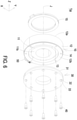
FIG. 5 is a schematic exploded view illustrating a load cell according to a second embodiment of the present disclosure; -
FIG. 6 is a schematic exploded view illustrating the load cell according to the second embodiment of the present disclosure and taken from another perspective angle; -
FIG. 7 is a schematic exterior view illustrating the load cell according to the second embodiment of the present disclosure; -
FIG. 8 shows a cross-sectional structure of the load cell according to the second embodiment of the present disclosure; -
FIG. 9 is a schematic cross-sectional view illustrating the load cell according to the second embodiment of the present disclosure; -
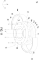
FIG. 10 is a schematic exploded view illustrating a load cell according to a third embodiment of the present disclosure; -
FIG. 11 is a schematic exploded view illustrating the load cell according to the third embodiment of the present disclosure and taken from another perspective angle; -
FIG. 12 is a schematic exterior view illustrating the load cell according to the third embodiment of the present disclosure; -
FIG. 13 shows a cross-sectional structure of the load cell according to the third embodiment of the present disclosure; and -
FIG. 14 is a schematic cross-sectional view illustrating the load cell according to the third embodiment of the present disclosure. - The present disclosure will now be described more specifically with reference to the following embodiments. It is to be noted that the following descriptions of preferred embodiments of this disclosure are presented herein for purpose of illustration and description only. It is not intended to be exhaustive or to be limited to the precise form disclosed.
- Please refer to
FIGS. 1 to 3 . In a first embodiment of the present disclosure, aload cell 1 is provided and includes anelastic element 10, at least onestrain gauge 20 and alimitation element 30. Theelastic element 10 is disc-shaped and includes a firstmain body 11, a secondmain body 12 and aconnection portion 13. The secondmain body 12 is disposed around an outer periphery of the firstmain body 11. The firstmain body 11 and the secondmain body 12 are concentric with each other. Preferably but not exclusively, the direction of the central axis J of theload cell 1 is parallel to the Z-axis direction. In that, the Z-axis is regarded as an axial direction. Theconnection portion 13 is connected between the firstmain body 11 and the secondmain body 12. In other words, each of the firstmain body 11, the secondmain body 12 and theconnection portion 13 is formed in a ring shape, and the firstmain body 11, theconnection portion 13 and the secondmain body 12 are sequentially disposed along a radial direction. In the embodiment, the firstmain body 11, the secondmain body 12 and theconnection portion 13 are configured to form afirst end portion 11a, asecond end portion 12b and adeformation region 13a, respectively. Preferably but not exclusively, thefirst end portion 11a is a stressed end located at a top surface of the firstmain body 11, and thesecond end portion 12b is a mounted end located at a bottom surface of the secondmain body 12. In addition, the top surface (i.e., thefirst end portion 11a) of the firstmain body 11 is more convex than thetop surface 12a of the secondmain body 12 to form a stepped structure, so that thefirst end portion 11a is served as the stressed end. The bottom surface (i.e., thesecond end portion 12b) of the secondmain body 12 is more convex than thebottom surface 11b of the firstmain body 11 to form a stepped structure, so that thesecond end portion 12b is served as the mounted end. In the embodiment, thefirst end portion 11a and thesecond end portion 12b are arranged along the axial direction. Preferably but not exclusively, thefirst end portion 11a and thesecond end portion 12b are two opposed surfaces. Thedeformation region 13a is located between thefirst end portion 11a and thesecond end portion 12b. Moreover, in the embodiment, the at least onestrain gauge 20 is disposed in thedeformation region 13a. Preferably but not exclusively, thedeformation region 13a and the at least onestrain gauge 20 are extended along a second direction such as the radial direction. The second direction such as the radial direction is parallel to the XY plane and different from the axial direction (i.e., the Z-axis direction). In the embodiment, thelimitation element 30 is connected to theelastic element 10. A gap G is formed between thelimitation element 30 and theelastic element 10 in the axial direction. - In the embodiment, the at least one
strain gauge 20 is illustrated by four strain gauges S1 to S4. The four strain gauges S1 to S4 are secured on the top surface and the bottom surface of theconnection portion 13, respectively. Preferably but not exclusively, the strain gauge S1 and the strain gauge S4 are two strain gauges spatially corresponding to each other, and are symmetrically disposed on the top surface and the bottom surface of theconnection portion 13, respectively. Preferably but not exclusive, the strain gauge S2 and the strain gauge S3 are two strain gauges spatially corresponding to each other, and are symmetrically disposed on the top surface and the bottom surface of theconnection portion 13, respectively. Preferably but not exclusively, theelastic element 10 of theload cell 1a is made of aluminum, alloy steel, or stainless steel. When the force F1 is exerted on thefirst end portion 11a of theload cell 1 in the first direction (i.e., the reverse of the Z-axis direction), the firstmain body 11 is moved relative to the secondmain body 12, thedeformation region 13a formed on theconnection portion 13 is slightly deformed, and unless overloaded, always returns to its original shape. As thedeformation region 13a of theelastic element 10 deforms, the strain gauges S1 to S4 secured on thedeformation region 13a also change shape, so that the force F1 exerted is measured and standardized under a specific range. In the embodiment, each strain gauge S1 to S4 is constructed by a wire or a foil, which is set up in a zigzag pattern and attached to theconnection portion 13. In the embodiment, the four strain gauges S1 to S4 are set in a bridge circuit as shown inFIG. 2 . When the shape of the strain gauges S1 to S4 is altered, a change in its electrical resistances R1 to R4 occurs. The resulting alteration to the electrical resistances R1 to R4 in the strain gauges S1 to S4 can be measured as voltage V. The change in voltage V is proportional to the amount of the force F1 exerted on theload cell 1, thus the amount of force can be calculated from the output ofload cell 1. - In the embodiment, when a force F1 is exerted on the
first end portion 11a in the first direction (i.e., the reverse of the Z-axis direction), theconnection portion 13 in thedeformation region 13a is deformed to drive the at least onestrain gauge 20 to change shape. The force F1 is converted into an electrical signal, so that the force F1 is measured and standardized under a specific range. As the force F1 exerted on theload cell 1 increases, the electrical signal changes proportionally. Preferably but not exclusively, as the force F1 exerted on thefirst end portion 11a of theload cell 1, tension force stretches the strain gauges S3 and S4, and the wires of the strain gauges S3 and S4 get longer, so that it results in an increase in the electrical resistances R3 and R4. Compression force does the opposite. As the force F1 exerted on thefirst end portion 11a of theload cell 1, the strain gauges S1 and S2 are compressed, and the wires of strain gauges S1 and S2 get shorter, and the electrical resistances R1 and R2 are decreased. With the strain gauges S1 to S4 attached to thedeformation region 13a of theelastic element 10, it facilitates theload cell 1 to mirror the minute changes to be measured. Moreover, the force F1 exerted thereon is measured and standardized under a specific range. Certainly, the present disclosure is not limited thereto. - On the other hand, in the embodiment, the
top surface 31 of thelimitation element 30 is connected to thesecond end portion 12b of the secondmain body 12 of theelastic element 10, and thetop surface 31 of thelimitation element 30 spatially corresponds to thebottom surface 11b of the firstmain body 11, so that a gap G is formed in the axial direction. In the embodiment, the gap G further includes a spaced distance D. When the force F1 is exerted on thefirst end portion 11a of theload cell 1 for example along the first direction such as the axial direction (i.e., the reverse of the Z-axis direction), theconnection portion 13 of theelastic element 10 is subjected to deformation, and the spaced distance D of the corresponding gap G is gradually reduced. Until the spaced distance D of the gap G is disappeared, the force F1 under the specific range and exerted on theload cell 1 is measured by theload cell 1 accurately. - On the other hand,
FIG. 4 shows the maximum deformation of the load cell when the load cell is overloaded according to the first embodiment of the present disclosure. When an excessive force F2 over the specific range is exerted on theload cell 1, the spaced distance D of the corresponding gap G is completely disappeared, and thebottom surface 11b of the firstmain body 11 is supported by thetop surface 31 of thelimitation element 30, so that the deformation of theelastic element 10 of theload cell 1 is limited in a certain space. In other words, the spaced distance D is inversely proportional to the force F1. When the spaced distance D in the gaps G is reduced to zero, the excessive force F2 is greater than the specific range, and the firstmain body 11 of theelastic element 10 is supported by thelimitation element 30 to limit deformation of theelastic element 10. Preferably but not exclusively, theload cell 1 includes the gap G having the spaced distance D at 0.1 mm between thelimitation element 30 and theelastic element 10, and is utilized to measure the force F1 under 20 tons. Moreover, in the embodiment, thelimitation element 30 further includes aprotrusion 31a disposed on thetop surface 31 and spatially corresponding to thebottom surface 11b of the firstmain body 11. The height of theprotrusion 31a is adjustable according to the practical requirements, so as to achieve the required spaced distance D of the gap G. Certainly, the present disclosure is not limited thereto. - Please refer to
FIGS. 5 to 9 . In a second embodiment, the structures, elements and functions of theload cell 1a are similar to those of theload cell 1 inFIGS. 1 to 4 . The elements and features indicated by the numerals similar to those of the foregoing embodiment mean similar elements and features, and are not redundantly described herein. In the embodiment, each of the firstmain body 11, the secondmain body 12 and theconnection portion 13 is formed in a ring shape, and the firstmain body 11, theconnection portion 13 and the secondmain body 12 are sequentially disposed along the radial direction and concentric with each other. Preferably but not exclusively, the firstmain body 11, theconnection portion 13 and the secondmain body 12 are integrally formed into one piece by the same material. In the embodiment, the top surface (i.e., thefirst end portion 11a) of the firstmain body 11 is more convex than thetop surface 12a of the secondmain body 12, so that thefirst end portion 11a of theload cell 1a is formed and served as the stressed end. The bottom surface (i.e., thesecond end portion 12b) of the secondmain body 12 is more convex than thebottom surface 11b of the firstmain body 11, so that thesecond end portion 12b is formed and connected to thetop surface 31 of thelimitation element 30. In addition, thebottom surface 11b of the firstmain body 11 is recessed from the bottom surface (i.e., thesecond end portion 12b) of the secondmain body 12, so as to form a stepped structure. It facilitates to form the gap G between thebottom surface 11b of the firstmain body 11 and thetop surface 31 of thelimitation element 30. In the embodiment, thebottom surface 32 of thelimitation element 30 is served as the mounted end of theload cell 1a. In the embodiment, thefirst end portion 11a of the firstmain body 11 and thesecond end portion 12b of the secondmain body 12 are misaligned in the axial direction. Moreover, the gap G spatially corresponds to thefirst end portion 11a, and is formed between thebottom surface 11b of the firstmain body 11 and thetop surface 31 of thelimitation element 30. In the embodiment, thesecond end portion 12b of the secondmain body 12 further incudes a plurality of first fastened holes 14. Thelimitation element 30 includes a plurality of second fastenedholes 33 passing through thetop surface 31 and thebottom surface 32 and spatially corresponding to the first fastened holes 14. Theload cell 1a further includes a plurality offastening elements 40. Each of thefastening elements 40 is passing through and engaged with the corresponding second fastenedhole 33 of thelimitation element 30 and the corresponding first fastenedhole 14 of the secondmain body 12, so as to connect thesecond end portion 12b of the secondmain body 12 with thetop surface 31 of thelimitation element 30. Moreover, the gap G is formed between thebottom surface 11b of the firstmain body 11 and thetop surface 31 of thelimitation element 30, and spatially corresponds to thefirst end portion 11a of the firstmain body 11 in the axial direction. In other embodiments, theelastic element 10 and thelimitation element 30 are integrally formed into one piece, and made of aluminum, alloy steel, or stainless steel. The present disclosure is not limited thereto. In the embodiment, the plurality ofstrain gauges 20 are arranged radially in thedeformation region 13a formed by theconnection portion 13 and served as a bridge circuit, which is configured to convert the force F1 (Referring toFIG. 3 ) into an electrical signal. In the embodiment, theload cell 1a further includes anadapter 50. Preferably but not exclusively, theadapter 50 is disposed on the outer periphery of the secondmain body 12, electrically connected to the strain gauges 20 and configured to transmit the electronic signal converted from the force F1. Moreover, in the embodiment, theload cell 1a further includes aprotective layer 15. Preferably but not exclusively, theprotective layer 15 spatially corresponds to thedeformation region 13a and the strain gauges 20, and covers the strain gauges 20 so that the strain gauges 20 are not exposed. It is advantageous of protecting the strain gauges 20 from being damaged by moisture or dust. Certainly, the present disclosure is not limited thereto. - In the embodiment, each gap G includes a spaced distance D in the axial direction. When the force F1 (Referring to
FIG. 3 ) is exerted on thefirst end portion 11a of theload cell 1a for example along the first direction (i.e., the reverse of the Z-axis direction), theconnection portion 13 of theelastic element 10 is subjected to deformation, and the spaced distance D of the corresponding gap G is gradually reduced. Until the spaced distance D of the gap G is disappeared, the force F1 under the specific range and exerted on theload cell 1a is measured by theload cell 1a accurately. On the other hand, when an excessive force F2 (Referring toFIG. 4 ) over the specific range is exerted on theload cell 1a, the spaced distance D of the corresponding gap G is completely disappeared, and thebottom surface 11b of the firstmain body 11 is supported by thetop surface 31 of thelimitation element 30, so that the deformation of theelastic element 10 of theload cell 1a is limited in a certain space. In other words, the spaced distance D is inversely proportional to the force F1. When the spaced distance D in the gaps G is reduced to zero, the excessive force F2 is greater than the specific range, and the firstmain body 11 of theelastic element 10 is supported by thelimitation element 30 to limit deformation of theelastic element 10. Preferably but not exclusively, theload cell 1a includes the gap G having the spaced distance D at 0.1 mm between thelimitation element 30 and theelastic element 10, and is utilized to measure the force F1 under 20 tons. Furthermore, with the design of the gap G disposed between thelimitation element 30 and the firstmain body 11 of theelastic element 10, an excessive force more than 20 tons exerted on theload cell 1a is affordable without damaging theelastic element 10 of theload cell 1a. Under the effect of supporting and limiting displacement through thelimitation element 30, it prevents theelastic element 10 of theload cell 1a from being damaged due to excessive force deformation. In other embodiments, the profiles of the firstmain body 11, theconnection portion 13 and the secondmain body 12 of theelastic element 10 and thelimitation element 30 are adjustable according to the practical requirements. The present disclosure is not limited thereto. - Please refer to
FIGS. 10 to 14 . In a third embodiment, the structures, elements and functions of theload cell 1b are similar to those of theload cell 1a inFIGS. 5 to 9 . The elements and features indicated by the numerals similar to those of the foregoing embodiment mean similar elements and features, and are not redundantly described herein. In the embodiment, the firstmain body 11 and the secondmain body 12 are stacked in the axial direction (i.e., the Z-axis direction) and concentric with each other. Preferably but not exclusively, the direction of the central axis J of theload cell 1b is parallel to the Z-axis direction. Namely, the Z-axis is regarded as the axial direction. In the embodiment, theconnection portion 13 is connected between the firstmain body 11 and the secondmain body 12. Thefirst end portion 11a and thesecond end portion 12b are formed on the top surface of the firstmain body 11 and thebottom surface 11b of the secondmain body 12, respectively, and thedeformation region 13a is formed on theconnection portion 13. In addition, thefirst end portion 11a of the firstmain body 11 is served as the stressed end of theload cell 1b, and thesecond end portion 12b of the secondmain body 12 is served as the mounted end of theload cell 1b. Thebottom surface 11b of the firstmain body 11 and thetop surface 12a of the secondmain body 12 are connected to two opposed ends of theconnection portion 13, respectively, so that thedeformation region 13a is formed between thebottom surface 11b of the firstmain body 11 and thetop surface 12a of the secondmain body 12. In the embodiment, thefirst end portion 11a and thesecond end portion 12b are opposed to each other in the axial direction, and the gap G is located between thefirst end portion 11a and thesecond end portion 12b. In the embodiment, thedeformation region 13a and the at least onestrain gauge 20 are extended along the axial direction (i.e., the Z-axis direction). - In the embodiment, the second
main body 12 further incudes a plurality of first fastenedholes 14 passing through thetop surface 12a and thesecond end portion 12b of the secondmain body 12. Thelimitation element 30a includes a plurality of second fastenedholes 33 disposed on thebottom surface 32 and spatially corresponding to the first fastened holes 14. Theload cell 1b further includes a plurality offastening elements 40. Each of thefastening elements 40 is passing through and engaged with the corresponding first fastenedhole 14 of the secondmain body 12 and the corresponding second fastenedhole 33 of thelimitation element 30a, so as to connect thesecond end portion 12b of the secondmain body 12 with thebottom surface 32 of thelimitation element 30a. Moreover, the gap G is formed between thebottom surface 11b of the firstmain body 11 and thetop surface 31 of thelimitation element 30a, and spatially corresponds to thefirst end portion 11a of the firstmain body 11 and thesecond end portion 12b of the secondmain body 12 in the axial direction. In other embodiments, theelastic element 10 and thelimitation element 30a are integrally formed into one piece, and made of aluminum, alloy steel, or stainless steel. The present disclosure is not limited thereto. In the embodiment, the plurality ofstrain gauges 20 are arranged radially in thedeformation region 13a formed by theconnection portion 13, and staggered with each other. The plurality ofstrain gauges 20 are served as a bridge circuit, which is configured to convert the force F1 (Referring toFIG. 3 ) into an electrical signal. In the embodiment, theload cell 1b further includes anadapter 50. Preferably but not exclusively, theadapter 50 is disposed on the outer periphery of the secondmain body 12, electrically connected to the strain gauges 20 and configured to transmit the electronic signal converted from the force F1. Moreover, in the embodiment, the firstmain body 11 further includes a plurality of throughholes 16 passing through thefirst end portion 11a and thebottom surface 11b thereof and in fluid communication with the outer periphery of theconnection portion 13. After theelastic element 10, the strain gauges 20 and thelimitation element 30a are assembled, a sealant (not shown) is filled through the throughholes 16 to cover the strain gauges 20 in thedeformation region 13a, and the strain gauges 20 are not exposed. It is advantageous of protecting the strain gauges 20 from being damaged by moisture or dust. Certainly, the present disclosure is not limited thereto. - In the embodiment, each gap G includes a spaced distance D in the axial direction. When the force F1 (Referring to
FIG. 3 ) is exerted on thefirst end portion 11a of theload cell 1b for example along the first direction (i.e., the reverse of the Z-axis direction), theconnection portion 13 of theelastic element 10 is subjected to deformation, and the spaced distance D of the corresponding gap G is gradually reduced. Until the spaced distance D of the gap G is disappeared, the force F1 under the specific range and exerted on theload cell 1b is measured by theload cell 1b accurately. On the other hand, when an excessive force F2 (Referring toFIG. 4 ) over the specific range is exerted on the load cell lb, the spaced distance D of the corresponding gap G is completely disappeared, and thebottom surface 11b of the firstmain body 11 is supported by thetop surface 31 of thelimitation element 30a, so that the deformation of theelastic element 10 of theload cell 1b is limited in a certain space. In other words, the spaced distance D is inversely proportional to the force F1. When the spaced distance D in the gaps G is reduced to zero, the excessive force F2 is greater than the specific range, and the firstmain body 11 of theelastic element 10 is supported by thelimitation element 30a to limit deformation of theelastic element 10. Preferably but not exclusively, theload cell 1b includes the gap G having the spaced distance D at 0.1 mm between thelimitation element 30 and theelastic element 10, and is utilized to measure the force F1 under 200 tons. Furthermore, with the design of the gap G disposed between thelimitation element 30a and the firstmain body 11 of theelastic element 10, an excessive force more than 200 tons exerted on theload cell 1b is affordable without damaging theelastic element 10 of theload cell 1b. Under the effect of supporting and limiting displacement through thelimitation element 30a, it prevents theelastic element 10 of theload cell 1a from being damaged due to excessive force deformation. In other embodiments, the profiles of the firstmain body 11, theconnection portion 13 and the secondmain body 12 of theelastic element 10 and thelimitation element 30a are adjustable according to the practical requirements. The present disclosure is not limited thereto. - From the above descriptions, the present disclosure provides a disc-type load cell capable of measuring a loading force under a specific range, and preventing the load cell from being damaged by irreversible permanent deformation due to overload. In order to avoid the irreversible permanent deformation and the material damage of the load cell due to overload, a limitation element with a special design is introduced into the structure of the load cell, and a gap is formed between the limitation element and the elastic element, so that the load cell is deformed in a specific space. Under the effects of the support of the limitation element and the limited displacement of the gap, it prevents the load cell from being damaged due to overload deformation. In addition, since the gap spatially corresponds to the strain gauge secured on the elastic element, when a sealant is filled into the gap to cover the strain gauge, it is helpful of protecting the strain gauge from being damaged by moisture or dust.
Claims (15)
- A load cell (1, 1a, 1b) comprising:an elastic element (10) comprising a first end portion (11a), a second end portion (12b) and a deformation region (13a), wherein the first end portion (11a) and the second end portion (12b) are arranged along an axial direction and opposed to each other, and the deformation region (13a) is located between the first end portion (11a) and the second end portion (12b);at least one strain gauge (S1, S2, S3, S4) disposed in the deformation region (13a), wherein when a force (F1) is exerted on the first end portion (11a) in a first direction, the deformation region (13a) is deformed to drive the at least one strain gauge (S1, S2, S3, S4) to change shape, so that the force (F1) is measured and standardized under a specific range; anda limitation element (30, 30a) connected to the elastic element (10), wherein a gap (G) is formed between the limitation element (30, 30a) and the elastic element (10).
- The load cell (1, 1a, 1b) according to claim 1, wherein the deformation region (13a) and the at least one strain gauge (S1, S2, S3, S4) are arranged along a second direction, and the second direction is different from the first direction.
- The load cell (1, 1a) according to claim 1, wherein the elastic element (10) comprises a first main body (11), a second main body (12) and a connection portion (13), the second main body (12) is disposed around an outer periphery of the first main body (11), and the connection portion (13) is connected between the first main body (11) and the second main body (12), wherein the first end portion (11a) and the second end portion (12b) are formed on the first main body (11) and the second main body (12), respectively, and the deformation region (13a) is formed on the connection portion (13).
- The load cell (1, 1a) according to claim 3, wherein each of the first main body (11), the second main body (12) and the connection portion (13) is formed in a ring shape, and the first main body (11), the connection portion (13) and the second main body (12) are sequentially disposed along a radial direction, wherein the first end portion (11a) is a stressed end located at a top surface of the first main body (11), and the second end portion (12b) is a mounted end located at a bottom surface of the second main body (12), wherein the first end portion (11a) and the second end portion (12b) are misaligned in the axial direction, and the gap (G) spatially corresponds to the first end portion (11a).
- The load cell (1b) according to claim 1, wherein the deformation region (13a) and the at least one strain gauge (S1, S2, S3, S4) are extended along the axial direction.
- The load cell (1b) according to claim 1, wherein the elastic element (10) comprises a first main body (11), a second main body (12) and a connection portion (13), the first main body (11) and the second main body (12) are stacked in the axial direction and concentric with each other, and the connection portion (13) is connected between the first main body (11) and the second main body (12), wherein the first end portion (11a) and the second end portion (12b) are formed on the first main body (11) and the second main body (12), respectively, and the deformation region (13) is formed on the connection portion (13).
- The load cell (1b) according to claim 6, wherein each of the first main body (11), the second main body (12) and the connection portion (13) is formed in a ring shape, wherein the first end portion (11a) is a stressed end located at a top surface of the first main body (11), and the second end portion (12b) is a mounted end located at a bottom surface of the second main body (12), wherein the first end portion (11a) and the second end portion (12b) are opposed to each other in the axial direction, and the gap (G) is located between the first end portion (11a) and the second end portion (12b).
- The load cell (1, 1a, 1b) according to claim 1, wherein the at least one strain gauge (S1, S2, S3, S4) comprises a plurality of strain gauges (S1, S2, S3, S4) arranged radially in the deformation region (13a) and served as a bridge circuit, which is configured to convert the force (F1) into an electrical signal.
- The load cell (1, 1a, 1b) according to claim 1, wherein the gap (G) comprises a spaced distance (D), and the spaced distance (D) is inversely proportional to the force (F1), wherein when the spaced distance (D) is reduced to zero, the force (F2) is greater than the specific range, and the elastic element (10) is supported by the limitation element (30, 30a) to limit deformation of the deformation region (13a).
- A load cell (1, 1a, 1b) comprising:a first main body (11) comprising a first end portion (11a);a second main body (12) comprising a second end portion (12b);a connection portion (13) connected between the first main body (11) and the second main body (12) and comprising a deformation region (13a), wherein the first end portion (11) and the second end portion (12) are arranged along an axial direction;at least one strain gauge (S1, S2, S3, S4) disposed in the deformation region (13a), wherein when a force (F1) is exerted on the first end portion (11a) in a first direction, the deformation region (13a) is deformed to drive the at least one strain gauge (S1, S2, S3, S4) to change shape, so that the force (F1) is measured and standardized under a specific range; anda limitation element (30, 30a) connected to the second main body (12), wherein a gap (G) is formed between the limitation element (30, 30a) and the first main body (11).
- The load cell (1, 1a) according to claim 10, wherein each of the first main body (11), the second main body (12) and the connection portion (13) is formed in a ring shape, and the first main body (11), the connection portion (13) and the second main body (12) are sequentially disposed along a radial direction, wherein the first end portion (11a) is a stressed end located at a top surface of the first main body (11), and the second end portion (12b) is a mounted end located at a bottom surface of the second main body (12), wherein the first end portion (11a) and the second end portion (12b) are misaligned in the axial direction, and the gap (G) spatially corresponds to the first end portion (11a).
- The load cell (1b) according to claim 10, wherein each of the first main body (11), the second main body (12) and the connection portion (13) is formed in a ring shape, wherein the first main body (11), the connection portion (13) and the second main body (12) are stacked in the first direction.
- The load cell (1, 1a, 1b) according to claim 10, wherein the first end portion (11a) is a stressed end located at a top surface of the first main body (11), and the second end portion (12b) is a mounted end located at a bottom surface of the second main body (12), and the gap (G) is located between the first end portion (11a) and the second end portion (12b).
- The load cell (1, 1a, 1b) according to claim 10, wherein the at least one strain gauge (S1, S2, S3, S4) comprises a plurality of strain gauges (S1, S2, S3, S4) arranged radially in the deformation region (13a) and served as a bridge circuit, which is configured to convert the force (F1) into an electrical signal.
- The load cell (1, 1a, 1b) according to claim 10, wherein the gap (G) comprises a spaced distance (D), and the spaced distance (D) is inversely proportional to the force (F1), wherein when the spaced distance (D) is reduced to zero, the force (F2) is greater than the specific range, and the first main body (11) is supported by the limitation element (30, 30a) to limit deformation of the deformation region (13a).
Applications Claiming Priority (2)
| Application Number | Priority Date | Filing Date | Title |
|---|---|---|---|
| US202063079568P | 2020-09-17 | 2020-09-17 | |
| US17/241,931 US11821782B2 (en) | 2020-09-17 | 2021-04-27 | Load cell for measuring a loading force under a specific range with limitation element to prevent irreversible deformation |
Publications (2)
| Publication Number | Publication Date |
|---|---|
| EP3971546A1 true EP3971546A1 (en) | 2022-03-23 |
| EP3971546B1 EP3971546B1 (en) | 2026-05-06 |
Family
ID=75914391
Family Applications (1)
| Application Number | Title | Priority Date | Filing Date |
|---|---|---|---|
| EP21173551.9A Active EP3971546B1 (en) | 2020-09-17 | 2021-05-12 | Load cell |
Country Status (5)
| Country | Link |
|---|---|
| US (1) | US11821782B2 (en) |
| EP (1) | EP3971546B1 (en) |
| JP (1) | JP3233210U (en) |
| CN (1) | CN216012549U (en) |
| TW (1) | TWM624268U (en) |
Cited By (1)
| Publication number | Priority date | Publication date | Assignee | Title |
|---|---|---|---|---|
| EP4681902A1 (en) * | 2024-07-19 | 2026-01-21 | ARBURG GmbH + Co KG | Injection force sensor assembly, injection molding unit and injection molding machine equipped with same |
Families Citing this family (4)
| Publication number | Priority date | Publication date | Assignee | Title |
|---|---|---|---|---|
| CN114643822B (en) * | 2022-04-08 | 2024-03-26 | 徐州徐工矿业机械有限公司 | Rubber damping device with pressure monitoring function, monitoring method and engineering vehicle |
| CN114910202A (en) * | 2022-05-31 | 2022-08-16 | 江汉大学 | Intelligent wearable sensor and detection method thereof |
| CN116124342A (en) * | 2022-12-30 | 2023-05-16 | 中航光电华亿(沈阳)电子科技有限公司 | Stress detection device for measuring pantograph of train |
| KR102912381B1 (en) * | 2025-05-28 | 2026-01-15 | 주식회사에스에이티 | Abnormal driving detection device in overload detection system |
Citations (4)
| Publication number | Priority date | Publication date | Assignee | Title |
|---|---|---|---|---|
| US3365689A (en) * | 1966-04-26 | 1968-01-23 | Kutsay Ali Umit | Strain gage apparatus |
| US6005199A (en) * | 1997-08-28 | 1999-12-21 | Kawatetsu Advantech Co., Ltd. | Load cell and load detecting apparatus |
| US8726741B2 (en) * | 2009-02-06 | 2014-05-20 | Abb Ag | Set of multiaxial force and torque sensor and assembling method |
| WO2020158166A1 (en) * | 2019-01-28 | 2020-08-06 | 日本電産コパル電子株式会社 | Elastic body and force sensor using same |
Family Cites Families (19)
| Publication number | Priority date | Publication date | Assignee | Title |
|---|---|---|---|---|
| US3771359A (en) * | 1972-05-17 | 1973-11-13 | Gse Inc | Load cell |
| US4283941A (en) * | 1979-05-08 | 1981-08-18 | Kutsay Ali U | Double shear beam strain gage load cell |
| HU189359B (en) * | 1983-11-11 | 1986-06-30 | Magyar Optikai Muevek,Hu | Complex meassuring device for high-accuracy strain gauge force meters |
| JPH0696251B2 (en) * | 1987-07-24 | 1994-11-30 | ファナック株式会社 | Injection molding machine |
| US5111702A (en) * | 1990-06-22 | 1992-05-12 | Hottinger Baldwin Measurements, Inc. | Torsion ring transducer |
| JPH0477226A (en) * | 1990-07-18 | 1992-03-11 | Nissei Plastics Ind Co | Injection molder |
| JP2515645B2 (en) * | 1991-09-18 | 1996-07-10 | ティアック株式会社 | Load cell and its processing method |
| JP3430366B2 (en) * | 1999-09-22 | 2003-07-28 | 日精樹脂工業株式会社 | Pressure detection device and pressure detection method for injection molding machine |
| AT5443U1 (en) * | 2001-07-09 | 2002-07-25 | Engel Gmbh Maschbau | EQUIPMENT FOR FORCE PRESSURE MONITORING IN INJECTION MOLDING MACHINES |
| CN1283985C (en) | 2003-04-17 | 2006-11-08 | 合肥工业大学 | Overload protection device for multi-axial force sensor |
| US7100458B2 (en) * | 2003-05-22 | 2006-09-05 | Crane Nuclear, Inc. | Flexure system for strain-based instruments |
| DE102005027264B4 (en) | 2005-06-13 | 2007-05-31 | Karl Hehl | Apparatus and method for detecting a force on an injection molding machine |
| DE102006034086B4 (en) * | 2006-07-20 | 2009-06-18 | Schenck Process Gmbh | Load cell |
| CN201165062Y (en) | 2007-11-27 | 2008-12-17 | 信义集团公司 | Intellectualized pressing apparatus |
| DE102008057796B4 (en) * | 2008-11-17 | 2012-12-13 | Schenck Process Gmbh | Wägedisc |
| CN102859050B (en) | 2010-03-29 | 2015-07-15 | 住友电气工业株式会社 | Method for producing semiconductor single crystal |
| CN102672987B (en) | 2011-03-17 | 2015-01-07 | 协易机械工业股份有限公司 | Crankshaft press with double protection mechanism and control method |
| TWM442500U (en) | 2012-06-12 | 2012-12-01 | Prec Machinery Res & Dev Ct | Strain ring |
| DE102016116182A1 (en) * | 2016-08-01 | 2018-02-01 | Nuton GmbH | Temperature management for a force measuring device |
-
2021
- 2021-04-27 US US17/241,931 patent/US11821782B2/en active Active
- 2021-05-12 EP EP21173551.9A patent/EP3971546B1/en active Active
- 2021-05-18 TW TW110205624U patent/TWM624268U/en unknown
- 2021-05-18 CN CN202121060746.3U patent/CN216012549U/en active Active
- 2021-05-20 JP JP2021001909U patent/JP3233210U/en active Active
Patent Citations (4)
| Publication number | Priority date | Publication date | Assignee | Title |
|---|---|---|---|---|
| US3365689A (en) * | 1966-04-26 | 1968-01-23 | Kutsay Ali Umit | Strain gage apparatus |
| US6005199A (en) * | 1997-08-28 | 1999-12-21 | Kawatetsu Advantech Co., Ltd. | Load cell and load detecting apparatus |
| US8726741B2 (en) * | 2009-02-06 | 2014-05-20 | Abb Ag | Set of multiaxial force and torque sensor and assembling method |
| WO2020158166A1 (en) * | 2019-01-28 | 2020-08-06 | 日本電産コパル電子株式会社 | Elastic body and force sensor using same |
Cited By (1)
| Publication number | Priority date | Publication date | Assignee | Title |
|---|---|---|---|---|
| EP4681902A1 (en) * | 2024-07-19 | 2026-01-21 | ARBURG GmbH + Co KG | Injection force sensor assembly, injection molding unit and injection molding machine equipped with same |
Also Published As
| Publication number | Publication date |
|---|---|
| US11821782B2 (en) | 2023-11-21 |
| TWM624268U (en) | 2022-03-11 |
| EP3971546B1 (en) | 2026-05-06 |
| CN216012549U (en) | 2022-03-11 |
| JP3233210U (en) | 2021-07-29 |
| US20220082432A1 (en) | 2022-03-17 |
Similar Documents
| Publication | Publication Date | Title |
|---|---|---|
| US11821782B2 (en) | Load cell for measuring a loading force under a specific range with limitation element to prevent irreversible deformation | |
| CN108801523B (en) | Force measuring elastic body for thrust bearing and force measuring device for thrust bearing | |
| US8904883B2 (en) | Load cell for monitoring torsion and having overload protection | |
| US6005199A (en) | Load cell and load detecting apparatus | |
| US8359932B2 (en) | Systems and methods for mounting landing gear strain sensors | |
| RU2317530C2 (en) | Sealed dynamometric device | |
| US3136157A (en) | Load cell apparatus | |
| US6612179B1 (en) | Method and apparatus for the determination of absolute pressure and differential pressure therefrom | |
| US9395256B2 (en) | Low profile multi-axis load cell | |
| EP0212942B1 (en) | Deflecting-diaphragm pressure sensors | |
| US20200200629A1 (en) | Multi-axis force sensor | |
| US3035240A (en) | Beam-diaphragm pressure load cell improvements | |
| US20120118067A1 (en) | Capacitive Pressure Sensor with Improved Electrode Structure | |
| CN112611489A (en) | Anti-overload torque sensor based on film sputtering | |
| US20020194923A1 (en) | Differential pressure sensor | |
| CN111174962B (en) | A capacitive three-dimensional force sensor with adjustable range | |
| US6216581B1 (en) | Fluid cylinder assembly | |
| US20200256750A1 (en) | Force sensor | |
| CN210198632U (en) | Double-range pressure sensor | |
| JP6696026B1 (en) | Load cell | |
| CN111122037A (en) | Sensor components, force detection equipment and construction machinery | |
| US11624669B2 (en) | Pressure sensor for high pressures | |
| CN219084269U (en) | force sensor | |
| EP2977731B1 (en) | Elastic body of weighing sensor | |
| WO2019171811A1 (en) | Torque sensor |
Legal Events
| Date | Code | Title | Description |
|---|---|---|---|
| PUAI | Public reference made under article 153(3) epc to a published international application that has entered the european phase |
Free format text: ORIGINAL CODE: 0009012 |
|
| STAA | Information on the status of an ep patent application or granted ep patent |
Free format text: STATUS: THE APPLICATION HAS BEEN PUBLISHED |
|
| STAA | Information on the status of an ep patent application or granted ep patent |
Free format text: STATUS: REQUEST FOR EXAMINATION WAS MADE |
|
| AK | Designated contracting states |
Kind code of ref document: A1 Designated state(s): AL AT BE BG CH CY CZ DE DK EE ES FI FR GB GR HR HU IE IS IT LI LT LU LV MC MK MT NL NO PL PT RO RS SE SI SK SM TR |
|
| 17P | Request for examination filed |
Effective date: 20220308 |
|
| RBV | Designated contracting states (corrected) |
Designated state(s): AL AT BE BG CH CY CZ DE DK EE ES FI FR GB GR HR HU IE IS IT LI LT LU LV MC MK MT NL NO PL PT RO RS SE SI SK SM TR |
|
| STAA | Information on the status of an ep patent application or granted ep patent |
Free format text: STATUS: EXAMINATION IS IN PROGRESS |
|
| 17Q | First examination report despatched |
Effective date: 20240613 |
|
| GRAP | Despatch of communication of intention to grant a patent |
Free format text: ORIGINAL CODE: EPIDOSNIGR1 |
|
| STAA | Information on the status of an ep patent application or granted ep patent |
Free format text: STATUS: GRANT OF PATENT IS INTENDED |
|
| INTG | Intention to grant announced |
Effective date: 20251216 |
|
| GRAS | Grant fee paid |
Free format text: ORIGINAL CODE: EPIDOSNIGR3 |
|
| GRAA | (expected) grant |
Free format text: ORIGINAL CODE: 0009210 |
|
| STAA | Information on the status of an ep patent application or granted ep patent |
Free format text: STATUS: THE PATENT HAS BEEN GRANTED |
|
| AK | Designated contracting states |
Kind code of ref document: B1 Designated state(s): AL AT BE BG CH CY CZ DE DK EE ES FI FR GB GR HR HU IE IS IT LI LT LU LV MC MK MT NL NO PL PT RO RS SE SI SK SM TR |
|
| REG | Reference to a national code |
Ref country code: CH Ref legal event code: F10 Free format text: ST27 STATUS EVENT CODE: U-0-0-F10-F00 (AS PROVIDED BY THE NATIONAL OFFICE) Effective date: 20260506 Ref country code: GB Ref legal event code: FG4D |