EP3971539A1 - Liquid sensor and hydraulic unit - Google Patents
Liquid sensor and hydraulic unit Download PDFInfo
- Publication number
- EP3971539A1 EP3971539A1 EP20805503.8A EP20805503A EP3971539A1 EP 3971539 A1 EP3971539 A1 EP 3971539A1 EP 20805503 A EP20805503 A EP 20805503A EP 3971539 A1 EP3971539 A1 EP 3971539A1
- Authority
- EP
- European Patent Office
- Prior art keywords
- liquid
- light
- liquid sensor
- sensor
- hydraulic oil
- Prior art date
- Legal status (The legal status is an assumption and is not a legal conclusion. Google has not performed a legal analysis and makes no representation as to the accuracy of the status listed.)
- Granted
Links
Images




Classifications
-
- G—PHYSICS
- G01—MEASURING; TESTING
- G01N—INVESTIGATING OR ANALYSING MATERIALS BY DETERMINING THEIR CHEMICAL OR PHYSICAL PROPERTIES
- G01N33/00—Investigating or analysing materials by specific methods not covered by groups G01N1/00 - G01N31/00
- G01N33/26—Oils; Viscous liquids; Paints; Inks
- G01N33/28—Oils, i.e. hydrocarbon liquids
- G01N33/2888—Lubricating oil characteristics, e.g. deterioration
-
- G—PHYSICS
- G01—MEASURING; TESTING
- G01F—MEASURING VOLUME, VOLUME FLOW, MASS FLOW OR LIQUID LEVEL; METERING BY VOLUME
- G01F23/00—Indicating or measuring liquid level or level of fluent solid material, e.g. indicating in terms of volume or indicating by means of an alarm
- G01F23/22—Indicating or measuring liquid level or level of fluent solid material, e.g. indicating in terms of volume or indicating by means of an alarm by measuring physical variables, other than linear dimensions, pressure or weight, dependent on the level to be measured, e.g. by difference of heat transfer of steam or water
- G01F23/28—Indicating or measuring liquid level or level of fluent solid material, e.g. indicating in terms of volume or indicating by means of an alarm by measuring physical variables, other than linear dimensions, pressure or weight, dependent on the level to be measured, e.g. by difference of heat transfer of steam or water by measuring the variations of parameters of electromagnetic or acoustic waves applied directly to the liquid or fluent solid material
- G01F23/284—Electromagnetic waves
- G01F23/292—Light, e.g. infrared or ultraviolet
- G01F23/2921—Light, e.g. infrared or ultraviolet for discrete levels
-
- F—MECHANICAL ENGINEERING; LIGHTING; HEATING; WEAPONS; BLASTING
- F15—FLUID-PRESSURE ACTUATORS; HYDRAULICS OR PNEUMATICS IN GENERAL
- F15B—SYSTEMS ACTING BY MEANS OF FLUIDS IN GENERAL; FLUID-PRESSURE ACTUATORS, e.g. SERVOMOTORS; DETAILS OF FLUID-PRESSURE SYSTEMS, NOT OTHERWISE PROVIDED FOR
- F15B1/00—Installations or systems with accumulators; Supply reservoir or sump assemblies
- F15B1/26—Supply reservoir or sump assemblies
-
- F—MECHANICAL ENGINEERING; LIGHTING; HEATING; WEAPONS; BLASTING
- F15—FLUID-PRESSURE ACTUATORS; HYDRAULICS OR PNEUMATICS IN GENERAL
- F15B—SYSTEMS ACTING BY MEANS OF FLUIDS IN GENERAL; FLUID-PRESSURE ACTUATORS, e.g. SERVOMOTORS; DETAILS OF FLUID-PRESSURE SYSTEMS, NOT OTHERWISE PROVIDED FOR
- F15B19/00—Testing; Calibrating; Fault detection or monitoring; Simulation or modelling of fluid-pressure systems or apparatus not otherwise provided for
-
- F—MECHANICAL ENGINEERING; LIGHTING; HEATING; WEAPONS; BLASTING
- F15—FLUID-PRESSURE ACTUATORS; HYDRAULICS OR PNEUMATICS IN GENERAL
- F15B—SYSTEMS ACTING BY MEANS OF FLUIDS IN GENERAL; FLUID-PRESSURE ACTUATORS, e.g. SERVOMOTORS; DETAILS OF FLUID-PRESSURE SYSTEMS, NOT OTHERWISE PROVIDED FOR
- F15B21/00—Common features of fluid actuator systems; Fluid-pressure actuator systems or details thereof, not covered by any other group of this subclass
- F15B21/04—Special measures taken in connection with the properties of the fluid
- F15B21/042—Controlling the temperature of the fluid
- F15B21/0423—Cooling
-
- G—PHYSICS
- G01—MEASURING; TESTING
- G01F—MEASURING VOLUME, VOLUME FLOW, MASS FLOW OR LIQUID LEVEL; METERING BY VOLUME
- G01F23/00—Indicating or measuring liquid level or level of fluent solid material, e.g. indicating in terms of volume or indicating by means of an alarm
- G01F23/02—Indicating or measuring liquid level or level of fluent solid material, e.g. indicating in terms of volume or indicating by means of an alarm by gauge glasses or other apparatus involving a window or transparent tube for directly observing the level to be measured or the level of a liquid column in free communication with the main body of the liquid
-
- G—PHYSICS
- G01—MEASURING; TESTING
- G01F—MEASURING VOLUME, VOLUME FLOW, MASS FLOW OR LIQUID LEVEL; METERING BY VOLUME
- G01F23/00—Indicating or measuring liquid level or level of fluent solid material, e.g. indicating in terms of volume or indicating by means of an alarm
- G01F23/22—Indicating or measuring liquid level or level of fluent solid material, e.g. indicating in terms of volume or indicating by means of an alarm by measuring physical variables, other than linear dimensions, pressure or weight, dependent on the level to be measured, e.g. by difference of heat transfer of steam or water
- G01F23/28—Indicating or measuring liquid level or level of fluent solid material, e.g. indicating in terms of volume or indicating by means of an alarm by measuring physical variables, other than linear dimensions, pressure or weight, dependent on the level to be measured, e.g. by difference of heat transfer of steam or water by measuring the variations of parameters of electromagnetic or acoustic waves applied directly to the liquid or fluent solid material
- G01F23/284—Electromagnetic waves
- G01F23/292—Light, e.g. infrared or ultraviolet
-
- G—PHYSICS
- G01—MEASURING; TESTING
- G01F—MEASURING VOLUME, VOLUME FLOW, MASS FLOW OR LIQUID LEVEL; METERING BY VOLUME
- G01F23/00—Indicating or measuring liquid level or level of fluent solid material, e.g. indicating in terms of volume or indicating by means of an alarm
- G01F23/30—Indicating or measuring liquid level or level of fluent solid material, e.g. indicating in terms of volume or indicating by means of an alarm by floats
-
- G—PHYSICS
- G01—MEASURING; TESTING
- G01F—MEASURING VOLUME, VOLUME FLOW, MASS FLOW OR LIQUID LEVEL; METERING BY VOLUME
- G01F23/00—Indicating or measuring liquid level or level of fluent solid material, e.g. indicating in terms of volume or indicating by means of an alarm
- G01F23/30—Indicating or measuring liquid level or level of fluent solid material, e.g. indicating in terms of volume or indicating by means of an alarm by floats
- G01F23/64—Indicating or measuring liquid level or level of fluent solid material, e.g. indicating in terms of volume or indicating by means of an alarm by floats of the free float type without mechanical transmission elements
- G01F23/68—Indicating or measuring liquid level or level of fluent solid material, e.g. indicating in terms of volume or indicating by means of an alarm by floats of the free float type without mechanical transmission elements using electrically actuated indicating means
- G01F23/686—Indicating or measuring liquid level or level of fluent solid material, e.g. indicating in terms of volume or indicating by means of an alarm by floats of the free float type without mechanical transmission elements using electrically actuated indicating means using opto-electrically actuated indicating means
-
- G—PHYSICS
- G01—MEASURING; TESTING
- G01F—MEASURING VOLUME, VOLUME FLOW, MASS FLOW OR LIQUID LEVEL; METERING BY VOLUME
- G01F23/00—Indicating or measuring liquid level or level of fluent solid material, e.g. indicating in terms of volume or indicating by means of an alarm
- G01F23/30—Indicating or measuring liquid level or level of fluent solid material, e.g. indicating in terms of volume or indicating by means of an alarm by floats
- G01F23/64—Indicating or measuring liquid level or level of fluent solid material, e.g. indicating in terms of volume or indicating by means of an alarm by floats of the free float type without mechanical transmission elements
- G01F23/68—Indicating or measuring liquid level or level of fluent solid material, e.g. indicating in terms of volume or indicating by means of an alarm by floats of the free float type without mechanical transmission elements using electrically actuated indicating means
- G01F23/70—Indicating or measuring liquid level or level of fluent solid material, e.g. indicating in terms of volume or indicating by means of an alarm by floats of the free float type without mechanical transmission elements using electrically actuated indicating means for sensing changes in level only at discrete points
- G01F23/706—Indicating or measuring liquid level or level of fluent solid material, e.g. indicating in terms of volume or indicating by means of an alarm by floats of the free float type without mechanical transmission elements using electrically actuated indicating means for sensing changes in level only at discrete points using opto-electrically actuated indicating means
-
- G—PHYSICS
- G01—MEASURING; TESTING
- G01N—INVESTIGATING OR ANALYSING MATERIALS BY DETERMINING THEIR CHEMICAL OR PHYSICAL PROPERTIES
- G01N21/00—Investigating or analysing materials by the use of optical means, i.e. using sub-millimetre waves, infrared, visible or ultraviolet light
- G01N21/17—Systems in which incident light is modified in accordance with the properties of the material investigated
- G01N21/25—Colour; Spectral properties, i.e. comparison of effect of material on the light at two or more different wavelengths or wavelength bands
- G01N21/27—Colour; Spectral properties, i.e. comparison of effect of material on the light at two or more different wavelengths or wavelength bands using photo-electric detection ; circuits for computing concentration
-
- G—PHYSICS
- G01—MEASURING; TESTING
- G01N—INVESTIGATING OR ANALYSING MATERIALS BY DETERMINING THEIR CHEMICAL OR PHYSICAL PROPERTIES
- G01N21/00—Investigating or analysing materials by the use of optical means, i.e. using sub-millimetre waves, infrared, visible or ultraviolet light
- G01N21/17—Systems in which incident light is modified in accordance with the properties of the material investigated
- G01N21/55—Specular reflectivity
-
- G—PHYSICS
- G01—MEASURING; TESTING
- G01N—INVESTIGATING OR ANALYSING MATERIALS BY DETERMINING THEIR CHEMICAL OR PHYSICAL PROPERTIES
- G01N21/00—Investigating or analysing materials by the use of optical means, i.e. using sub-millimetre waves, infrared, visible or ultraviolet light
- G01N21/17—Systems in which incident light is modified in accordance with the properties of the material investigated
- G01N21/59—Transmissivity
-
- G—PHYSICS
- G01—MEASURING; TESTING
- G01N—INVESTIGATING OR ANALYSING MATERIALS BY DETERMINING THEIR CHEMICAL OR PHYSICAL PROPERTIES
- G01N21/00—Investigating or analysing materials by the use of optical means, i.e. using sub-millimetre waves, infrared, visible or ultraviolet light
- G01N21/84—Systems specially adapted for particular applications
- G01N21/85—Investigating moving fluids or granular solids
-
- G—PHYSICS
- G08—SIGNALLING
- G08C—TRANSMISSION SYSTEMS FOR MEASURED VALUES, CONTROL OR SIMILAR SIGNALS
- G08C17/00—Arrangements for transmitting signals characterised by the use of a wireless electrical link
- G08C17/02—Arrangements for transmitting signals characterised by the use of a wireless electrical link using a radio link
-
- H—ELECTRICITY
- H02—GENERATION; CONVERSION OR DISTRIBUTION OF ELECTRIC POWER
- H02N—ELECTRIC MACHINES NOT OTHERWISE PROVIDED FOR
- H02N10/00—Electric motors using thermal effects
-
- H—ELECTRICITY
- H10—SEMICONDUCTOR DEVICES; ELECTRIC SOLID-STATE DEVICES NOT OTHERWISE PROVIDED FOR
- H10N—ELECTRIC SOLID-STATE DEVICES NOT OTHERWISE PROVIDED FOR
- H10N10/00—Thermoelectric devices comprising a junction of dissimilar materials, i.e. devices exhibiting Seebeck or Peltier effects
- H10N10/10—Thermoelectric devices comprising a junction of dissimilar materials, i.e. devices exhibiting Seebeck or Peltier effects operating with only the Peltier or Seebeck effects
-
- G—PHYSICS
- G01—MEASURING; TESTING
- G01F—MEASURING VOLUME, VOLUME FLOW, MASS FLOW OR LIQUID LEVEL; METERING BY VOLUME
- G01F23/00—Indicating or measuring liquid level or level of fluent solid material, e.g. indicating in terms of volume or indicating by means of an alarm
- G01F23/22—Indicating or measuring liquid level or level of fluent solid material, e.g. indicating in terms of volume or indicating by means of an alarm by measuring physical variables, other than linear dimensions, pressure or weight, dependent on the level to be measured, e.g. by difference of heat transfer of steam or water
- G01F23/28—Indicating or measuring liquid level or level of fluent solid material, e.g. indicating in terms of volume or indicating by means of an alarm by measuring physical variables, other than linear dimensions, pressure or weight, dependent on the level to be measured, e.g. by difference of heat transfer of steam or water by measuring the variations of parameters of electromagnetic or acoustic waves applied directly to the liquid or fluent solid material
- G01F23/284—Electromagnetic waves
- G01F23/292—Light, e.g. infrared or ultraviolet
- G01F23/2921—Light, e.g. infrared or ultraviolet for discrete levels
- G01F23/2928—Light, e.g. infrared or ultraviolet for discrete levels using light reflected on the material surface
-
- G—PHYSICS
- G01—MEASURING; TESTING
- G01N—INVESTIGATING OR ANALYSING MATERIALS BY DETERMINING THEIR CHEMICAL OR PHYSICAL PROPERTIES
- G01N2201/00—Features of devices classified in G01N21/00
- G01N2201/06—Illumination; Optics
- G01N2201/062—LED's
Definitions
- the present disclosure relates to liquid sensors and hydraulic units.
- Patent Literature 1 JP 2015-232582 A
- the present disclosure proposes a liquid sensor and a hydraulic unit capable of improving workability of attachment work.
- a liquid sensor of the present disclosure includes a light receiver configured to receive light.
- the light receiver is attachable to an outside of an accommodation unit into which a liquid is introduced and which has translucency.
- the light receiver receives light that has passed through the liquid in the accommodation unit or light reflected by the liquid, and outputs a signal related to a physical quantity of the liquid.
- the light receiver is attachable to the outside of the accommodation unit into which the liquid to be measured is introduced, a seal structure for preventing leakage of a hydraulic oil introduced into the accommodation unit to the outside is not required between the liquid sensor and the accommodation unit, and workability of attachment work of the liquid sensor to the accommodation unit can be improved.
- the translucency according to the present disclosure is translucency with respect to light passing through the liquid.
- the signal related to a physical quantity of the liquid includes a signal related to the deterioration degree of the liquid.
- the signal related to a physical quantity of the liquid includes a signal related to a hue of light that has passed through the liquid and has been received by the light receiver or light that has been reflected by the liquid and has been received by the light receiver.
- the deterioration degree of the liquid is determined from the hue.
- the signal related to a physical quantity of the liquid includes a signal related to presence or absence of the liquid in the accommodation unit.
- the accommodation unit includes a float disposed inside the accommodation unit.
- the float when the float is at a level at which the light receiver is attached to the accommodation unit, the float blocks light and significantly changes the intensity of light received by the light receiver. This allows the accuracy of detection of the presence or absence of liquid can be improved.
- the liquid sensor since the liquid sensor includes a rechargeable power source that supplies power to the light receiver and a thermoelectric conversion element that generates power for charging the power source, wiring for supplying power from the outside to the liquid sensor is not required, and the liquid sensor is allowed to have a simplified wiring structure.
- the liquid sensor includes a wireless transmitter configured to be supplied with electric power from the power source and to transmit the signal related to a physical quantity of the liquid of the light receiver to outside.
- the wiring structure can be simplified.
- the liquid sensor includes a light emitter configured to emit light.
- the light emitter is attachable to the outside of the accommodation unit.
- the light receiver receives light emitted by the light emitter and having passed through the liquid in the accommodation unit or light emitted by the light emitter and having been reflected by the liquid in the accommodation unit.
- the light emitter and the light receiver are arranged to face each other across the accommodation unit.
- the liquid sensor is a transmission type sensor in which the light emitter and the light receiver are arranged to face each other across the accommodation unit, it is possible to perform reliable detection as compared with a case where a sensor of another type is used as the liquid sensor.
- the light emitter and the light receiver are arranged on the same side with respect to the accommodation unit.
- the reflective sensor since a light emitter and a light receiver are arranged on the same side of an accommodating unit, the reflective sensor is smaller than other types of photoelectric sensors.
- the liquid sensor since the liquid sensor is a reflective sensor in which the light emitter and the light receiver are arranged on the same side of the accommodation unit, the liquid sensor can be made smaller than a case where a sensor of another type is used as the liquid sensor.
- the liquid sensor includes a casing attachable to the outside of the accommodation unit.
- the light emitter and the light receiver are integrally provided in the casing.
- the light emitter and the light receiver are integrally provided in the casing in a state where the optical axis of the light emitter and an optical axis of the light receiver coincide with each other, it is not necessary to adjust the optical axes of the light emitter and the light receiver to align the optical axes, when the liquid sensor is attached, so that workability of attachment work of the liquid sensor to the accommodation unit can be improved.
- a light emission manner that is, a manner in which the light emitter emits light, is determined according to the signal related to a physical quantity of the liquid of the light receiver.
- the liquid sensor notifies a user of information on the physical quantity of the liquid by the light emission manner of the light emitter. For example, when the detection result of the liquid sensor indicates an abnormality, the light emitter of the liquid sensor emits light in a light emission manner corresponding to the abnormality. In this way, so that the liquid sensor notifies the user that the liquid sensor has detected the abnormality. Thus, the user can easily recognize the information (for example, abnormality) on the physical quantity of the liquid to be measured by visually observing the light emission manner of the liquid sensor.
- the information for example, abnormality
- the light emitter of the liquid sensor has both a function as a projector of a photoelectric sensor and a function of notifying the user according to the signal related to the physical quantity of the liquid, the structure of the liquid sensor can be simplified as compared with a case where these functions are separately provided.
- the accommodation unit is a liquid level gauge.
- a liquid level gauge is installed at a place where a user can easily visually observe the liquid level gauge. Therefore, according to the above embodiment, since the liquid sensor is attached to the liquid level gauge, the user can easily visually observe the light emitter of the liquid sensor, so that the user can easily recognize the information (for example, abnormality) on the physical quantity of the liquid to be measured.
- the light emitter changes its state from off to blinking or blinking to off according to the signal related to a physical quantity of the liquid.
- the emission color changes according to the signal related to a physical quantity of the liquid.
- a hydraulic unit of one embodiment includes the liquid sensor described above.
- Fig. 1 is a perspective view of a hydraulic unit 1 according to a first embodiment of the present disclosure.
- the hydraulic unit 1 according to the present embodiment supplies hydraulic oil to an external apparatus such as a machine tool.
- the hydraulic unit 1 includes a hydraulic oil tank 10 that accommodates hydraulic oil, and a mount 11 attached to an upper portion of the hydraulic oil tank 10.
- the hydraulic unit 1 includes a hydraulic pump (not shown), a motor (not shown) that drives the hydraulic pump, an oil cooler 12 that cools hydraulic oil discharged from the hydraulic pump, and a controller 13 that controls the motor.
- the hydraulic pump, the motor, the oil cooler 12, and the controller 13 are mounted on the mount 11, and the hydraulic oil tank 10 is disposed below the mount 11.
- the hydraulic unit 1 includes a cooling fan 14 that supplies cooling air to the motor and the oil cooler 12.
- the hydraulic unit 1 is herein described by way of example only; and not limited to the above-described structure.
- a liquid level gauge 20 for externally checking the amount of the hydraulic oil accommodated in the hydraulic oil tank 10 is attached to a metal side surface 10a of the hydraulic oil tank 10. Since the liquid level gauge 20 is attached to the side surface 10a of the hydraulic oil tank 10, a user can easily visually check the amount of the hydraulic oil accommodated in the hydraulic oil tank 10.
- a liquid sensor 30 that measures a physical quantity (hue in the present embodiment) of liquid (hydraulic oil in the present embodiment) is attached to the outside of the liquid level gauge 20.
- Fig. 2 is a schematic front view showing the liquid level gauge 20 and the liquid sensor 30 according to the present embodiment.
- Fig. 3 is a schematic cross-sectional view taken along line III-III in Fig. 2 .
- illustration of a detailed structure of the inside of the liquid sensor 30 is omitted.
- the same components as in Fig. 1 are denoted by the same reference signs as in Fig. 1 .
- the liquid level gauge 20 of the present embodiment is an oil level gauge for checking the oil level of the hydraulic oil accommodated in the hydraulic oil tank 10.
- the liquid level gauge 20 of the present embodiment includes a liquid level gauge main body 21 made of a transparent acrylic resin and two bolts 22A and 22B for fixing the liquid level gauge main body 21 to the hydraulic oil tank 10.
- the liquid level gauge 20 according to the present embodiment is an example of a translucent accommodation unit into which the liquid (hydraulic oil in the present embodiment) according to the present disclosure is introduced.
- the liquid level gauge main body 21 of the present embodiment has a substantially rectangular parallelepiped shape, and is attached to the hydraulic oil tank 10 such that the liquid level gauge main body 21 has a longitudinal direction that extends along the vertical direction.
- the liquid level gauge main body 21 is hollow.
- the liquid level gauge main body 21 includes a hollow portion 21a being a space extending in the longitudinal direction inside the liquid level gauge main body 21.
- the hydraulic oil is introduced into the hollow portion 21a of the liquid level gauge main body 21 according to the amount of the hydraulic oil accommodated in the hydraulic oil tank 10.
- the user can check the amount of the hydraulic oil accommodated in the hydraulic oil tank 10 by visually observing the oil level of the hydraulic oil in the hollow portion 21a of the liquid level gauge main body 21.
- the liquid level gauge main body 21 is provided with an upper limit line HL indicating the upper limit of an allowable range of the oil level of the hydraulic oil and a lower limit line LL indicating the lower limit of the allowable range of the oil level of the hydraulic oil.
- each of the bolts 22A and 22B of the present embodiment are made of metal. As shown in Fig. 3 , each of the bolts 22A and 22B includes a communication portion 22c extending in the axial direction from a tip portion 22a toward a head portion 22b of the bolt. The communication portion 22c is open in the radial direction at an axial end portions on the head portion 22b side of each of the bolts 22A and 22B. In other words, the bolts 22A and 22B are what are called perforated bolts.
- the communication portions 22c of the bolts 22A and 22B fluidly connect the internal space of the hydraulic oil tank 10 to the hollow portion 21a of the liquid level gauge main body 21 in a state where the bolts 22A and 22B fix the liquid level gauge main body 21 to the hydraulic oil tank 10.
- the internal space of the hydraulic oil tank 10, the hollow portion 21a of the liquid level gauge main body 21, and the communication portion 22c of the bolts 22A and 22B communicate with each other.
- the communication portion 22c of the bolt 22B opens at the tip portion 22a into an area where the hydraulic oil accumulated in the hydraulic oil tank 10 exists. At this time, the hydraulic oil is introduced from the hydraulic oil tank 10 into the hollow portion 21a of the liquid level gauge main body 21 through the communication portion 22c of the bolt 22B. In addition, the communication portion 22c of the bolt 22B is filled with hydraulic oil.
- the oil level of the hydraulic oil introduced into the liquid level gauge main body 21 coincides with the oil level of the hydraulic oil accommodated in the hydraulic oil tank 10.
- the user can check the amount of the hydraulic oil accommodated in the hydraulic oil tank 10 by visually observing the oil level of the hydraulic oil in the hollow portion 21a of the liquid level gauge main body 21.
- the liquid sensor 30 of the present embodiment is a photoelectric sensor for detecting the degree of deterioration of the hydraulic oil accommodated in the hydraulic oil tank 10 and the presence or absence of the hydraulic oil. More specifically, the liquid sensor 30 is a transmissive color sensor. As shown in Fig. 2 , the liquid sensor 30 of the present embodiment includes a U-shaped casing 31, a light emitter 32 that emits light, and a light receiver 33 that receives the light emitted from the light emitter 32.
- the light emitter 32 and the light receiver 33 are provided integrally with the casing 31 so as to face each other. Specifically, the light emitter 32 and the light receiver 33 are provided integrally with the casing 31 so that the optical axis of the light emitter 32 and the optical axis of the light receiver 33 coincide with each other.
- the liquid sensor 30 is attached to the liquid level gauge main body 21 such that the light emitter 32 and the light receiver 33 face each other across the liquid level gauge main body 21.
- the liquid sensor 30 is attached to the liquid level gauge 20 such that the height positions of the light emitter 32 and the light receiver 33 overlap with the height position of the lower limit line LL of the liquid level gauge main body 21.
- the liquid sensor 30 detects the presence or absence of hydraulic oil below the lower limit line LL of the liquid level gauge main body 21.
- a packing (not shown) is provided between the casing 31 of the liquid sensor 30 and the liquid level gauge main body 21 of the present embodiment. This packing makes the casing 31 and the liquid level gauge main body 21 water-resistant and dust-resistant, prevents external light from entering the liquid level gauge main body 21, and brings the casing 31 into close contact with the liquid level gauge main body 21 so that the casing 31 is held by the liquid level gauge main body 21.
- the light emitter 32 of the present embodiment includes a light emitting element for emitting light and a drive circuit for driving the light emitting element.
- the light emitting element of the present embodiment is a white light emitting diode. In other words, the light emitter 32 of the present embodiment emits white light.
- the light receiver 33 of the present embodiment includes a light receiving element that converts the intensity of light into an electric signal, an amplifier circuit that amplifies the electric signal output from the light receiving element, and an A/D conversion circuit that converts the analog electric signal amplified by the amplifier circuit into a digital electric signal.
- the light receiving element of the present embodiment is an RGB color sensor, and can detect the electric signal converted from received visible light separately for each color of red, green, and blue.
- the liquid sensor 30 of the present embodiment further includes a thermoelectric conversion element 34 that converts heat into electric power.
- the thermoelectric conversion element 34 of the present embodiment is provided so as to be in contact with the side surface 10a of the hydraulic oil tank 10.
- the side surface 10a of the hydraulic oil tank 10 is likely to have a high temperature because the hydraulic oil accommodated in the hydraulic oil tank 10 has a high temperature due to heat generation from a sliding portion of the machine tool or the like.
- the thermoelectric conversion element 34 generates power using a temperature difference between the temperature of the side surface 10a of the hydraulic oil tank 10 and the temperature of the air around the liquid sensor 30.
- Fig. 4 is a schematic cross-sectional view taken along line IV-IV in Fig. 3 .
- illustration of a detailed structure of the inside of the liquid sensor 30 is omitted.
- Fig. 4 the same components as in Fig. 1 to 3 are denoted by the same reference signs as in Figs. 1 to 3 .
- the hollow portion 21a of the liquid level gauge main body 21 has a circular cross-sectional shape in the cross section shown in Fig. 4 .
- the optical axis XI of the light emitter 32 and the optical axis X2 of the light receiver 33 coincide with each other.
- the optical axis XI of the light emitter 32 and the optical axis X2 of the light receiver 33 extend to pass through the center C of the hollow portion 21a of the liquid level gauge main body 21.
- the optical axis XI of the light emitter 32 and the optical axis X2 of the light receiver 33 do not necessarily need to pass through the center C of the hollow portion 21a. It is preferable that the shortest distance from the optical axis XI of the light emitter 32 and the optical axis X2 of the light receiver 33 to the center C of the hollow portion 21a is 5 mm or less.
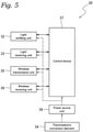
- Fig. 5 is a block diagram of the liquid sensor 30 of the present embodiment.
- the same components as in Figs. 1 to 3 are denoted by the same reference signs as in Figs. 1 to 3 .
- the liquid sensor 30 of the present embodiment includes a wireless transmitter 35 that wirelessly transmits a signal to an external apparatus, a wireless receiver 36 that wirelessly receives a signal from an external apparatus, and a control device 37.
- the liquid sensor 30 further includes a power source 38 for supplying (see a two-dot chain line in Fig. 5 ) power to each of the light emitter 32, the light receiver 33, the wireless transmitter 35, the wireless receiver 36, and the control device 37.
- the power source 38 of the present embodiment includes a rechargeable battery.
- the power source 38 is electrically connected to the thermoelectric conversion element 34.
- the thermoelectric conversion element 34 generates electric power for charging the power source 38 using a temperature difference between the hydraulic oil tank 10 (shown in Fig. 1 ) and air around the liquid sensor 30.
- the light emitter 32 of the liquid sensor 30 emits white light from the light emitting element with the power supplied from the power source 38.
- the light receiver 33 of the liquid sensor 30 receives light emitted from the light emitter 32 and having passed through the liquid level gauge main body 21 and the hydraulic oil in the liquid level gauge main body 21.
- the liquid sensor 30 transmits the light intensity of each of colors of red, green, and blue of light received by the light receiving element of the light receiver 33 to the controller 13 (shown in Fig. 1 ) of the hydraulic unit 1 via the wireless transmitter 35 as an electric signal.
- each of the red, green, and blue lights received by the light receiver 33 is light having a wavelength that was not absorbed by the hydraulic oil in the level gauge 20, it is possible to detect the hue of the hydraulic oil in the liquid level gauge 20 from the intensity of those lights transmitted by the light sensor 30.
- the light receiver 33 of the liquid sensor 30 according to the present embodiment converts the hue being an example of the physical quantity of the hydraulic oil into an electric signal and outputs the electric signal.
- the liquid sensor 30 according to the present disclosure outputs a signal related to a physical quantity (hue in the present embodiment) of liquid (hydraulic oil in the present embodiment).
- the translucency of the liquid level gauge 20 according to the present disclosure is translucency with respect to light (white light in the present embodiment) emitted by the light emitter 32.
- the controller 13 (shown in Fig. 1 ) of the hydraulic unit 1 of the present embodiment determines the degree of deterioration of the hydraulic oil and the presence or absence of the hydraulic oil based on the signal related to the hue of the hydraulic oil output from the liquid sensor 30.
- the liquid sensor 30 of the present embodiment outputs a signal related to the degree of deterioration of the hydraulic oil and a signal related to the presence or absence of the hydraulic oil.
- the degree of deterioration of the hydraulic oil and the presence or absence of the hydraulic oil are examples of physical quantities of the liquid (hydraulic oil in the present embodiment) according to the present disclosure.
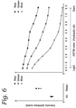
- Fig. 6 is an example of a calibration curve related to the hue used to determine the degree of deterioration of the hydraulic oil and the presence or absence of the hydraulic oil in the present embodiment.
- Fig. 6 shows the intensity [arbitrary scale] of light for each color of red, green, and blue for air, water, and the hydraulic oil having different hues.
- the hue of the hydraulic oil is represented using an ASTM color measured conforming to ASTM D1500.
- the ASTM color numerically indicates the hue of the hydraulic oil by a color scale ranging from 0.5 of a light color to 8.0 of a dark color in increments of 0.5.
- the ASTM color is an index of the degree of deterioration of the hydraulic oil, and indicates that the larger the value of the ASTM color, the more the hydraulic oil is deteriorated.
- the calibration curve (or calibration table) as shown in Fig. 6 is stored in the controller 13 (shown in Fig. 1 ) of the hydraulic unit 1.
- the controller 13 (shown in Fig. 1 ) of the hydraulic unit 1 determines the degree of deterioration of the hydraulic oil and the presence or absence of the hydraulic oil using the electric signals for each color of the red, green, and blue output from the liquid sensor 30 and the calibration curve shown in Fig. 6 . Specifically, the controller 13 of the hydraulic unit 1 compares the intensity (hereinafter, referred to as a measurement result of the liquid sensor 30) of light for each color of red, green, and blue for the hydraulic oil to be measured, which are calculated from the output voltage of the light receiver 33 of the liquid sensor 30, with the calibration curve shown in Fig. 6 .
- the degree of deterioration of the hydraulic oil is calculated from the measurement result of the liquid sensor 30 using the calibration curve for the ASTM color in Fig. 6 .
- the presence or absence of the hydraulic oil is determined based on whether or not the measurement result of the liquid sensor 30 indicates air by comparing the measurement result of the liquid sensor 30 with the calibration curve in Fig. 6 . If determining that the measurement result of the liquid sensor 30 indicates air, the controller 13 of the hydraulic unit 1 determines that there is no hydraulic oil at the detection position (in the present embodiment, below the lower limit line LL) of the liquid sensor 30.
- the measurement using the liquid sensor 30 described above is preferably performed after it is determined that the hydraulic unit 1 is in a stable operation state by referring to the operation time or the oil temperature rise after the start of the hydraulic unit 1.
- the liquid sensor 30 notifies the user of information on the physical quantity of the liquid (for example, abnormality) based on the light emission manner of the light emitter 32. Specifically, the liquid sensor 30 notifies the user of the abnormalities related to the deterioration degree of the hydraulic oil and the presence or absence of the hydraulic oil based on the light emission manner of the light emitter 32.
- the controller 13 of the hydraulic unit 1 when the controller 13 (shown in Fig. 1 ) of the hydraulic unit 1 determines that the hydraulic oil has deteriorated more than the predetermined deterioration degree, or determines that there is no hydraulic oil at the detection position, the controller 13 of the hydraulic unit 1 transmits a control signal for controlling the light emitter 32 to the liquid sensor 30.
- the control device 37 controls the light emitter 32 so that the light emission manner of the light emitter 32 changes according to contents to be notified.
- the liquid sensor 30 notifies the user of the abnormality (deterioration in hydraulic oil or decrease in hydraulic oil amount).
- the predetermined deterioration degree is, for example, a deterioration degree when the ASTM color becomes dark to 2.5 or more.
- the light emission manner of the light emitter 32 is determined according to contents to be notified (in the present embodiment, deterioration of hydraulic oil and decrease in hydraulic oil amount). In other words, in the light emitter 32 of the present embodiment, the light emission manner is determined according to the signal related to the physical quantity of the hydraulic oil. When the deterioration of the hydraulic oil is notified, the light emitter 32 of the present embodiment blinks. In other words, when the deterioration of the hydraulic oil is notified, the light emission manner of the light emitter 32 changes from off to blinking. In addition, when the decrease in the hydraulic oil amount is notified, the light emitter 32 of the present embodiment is turned on.
- the light emission manner of the light emitter 32 changes from off to on.
- the light emission manner of the light emitter 32 may change a blinking pattern such as a blinking interval and a blinking speed according to contents to be notified.
- the controller 13 (shown in Fig. 1 ) of the hydraulic unit 1 may display a numerical value (for example, ASTM color value) or a color in accordance with the level of the deterioration degree of the hydraulic oil on a display unit 13a provided in the controller 13, a display unit (not shown) provided in an external apparatus to which the hydraulic unit 1 supplies the hydraulic oil, or the like.
- a numerical value for example, ASTM color value
- a display unit not shown
- the controller 13 (shown in Fig. 1 ) of the hydraulic unit 1 may notify the user of deterioration of the hydraulic oil before the hydraulic oil needs to be replaced.
- the controller 13 of the hydraulic unit 1 may notify the user of the deterioration of the hydraulic oil by causing the light emitter 32 to emit light even before the ASTM color becomes dark to 2.5 or more, for example. In this case, as the deterioration of the hydraulic oil progresses, the frequency of light emission of the light emitter 32 may increase.
- liquid sensor 30 of the present disclosure since the light emitter 32 and the light receiver 33 are attached to the outside of the liquid level gauge 20 into which the hydraulic oil to be measured is introduced, a seal structure for preventing leakage of the hydraulic oil introduced into the liquid level gauge 20 to the outside is not required between the liquid sensor 30 and the liquid level gauge 20, and workability of attachment work of the liquid sensor 30 to the liquid level gauge 20 can be improved.
- the surface of the liquid level gauge 20 has less influence on the detection accuracy than in other types of photoelectric sensors.
- the liquid sensor 30 is a transmission type sensor, it is possible to perform reliable detection as compared with a case where a sensor of another type is used as the liquid sensor 30.
- the light emitter 32 and the light receiver 33 are integrally provided in the casing 31 in a state where the optical axis of the light emitter 32 and the optical axis of the light receiver 33 are made to coincide with each other, it is not necessary to adjust the optical axes of the light emitter and the light receiver when the liquid sensor 30 is attached, so that workability of attachment work of the liquid sensor 30 to the liquid level gauge 20 can be improved.
- the liquid sensor 30 since the liquid sensor 30 includes the rechargeable power source 38 that supplies power to the light emitter 32 and the light receiver 33 and the thermoelectric conversion element 34 that generates power for charging the power source 38, wiring for supplying power from the outside to the liquid sensor 30 is not required, and the wiring structure can be simplified.
- the detection result of the liquid sensor 30 is transmitted to the controller 13 of the hydraulic unit 1 via the wireless transmitter 35, there is no need for wiring for outputting the signal output from the light receiver 33 to the outside, and the wiring structure can be simplified.
- the liquid sensor 30 notifies the user of information on the physical quantity of the hydraulic oil by the light emission manner of the light emitter 32.
- the detection result of the liquid sensor 30 indicates an abnormality
- the light emitter 32 of the liquid sensor 30 emits light in a light emission manner corresponding to the abnormality, whereby the liquid sensor 30 notifies the user that the liquid sensor 30 has detected the abnormality.
- the user can easily recognize the information (for example, abnormality) on the physical quantity of the hydraulic oil by visually observing the light emission manner of the liquid sensor 30.
- the light emitter 32 of the liquid sensor 30 has both a function as a projector of a photoelectric sensor and a function of notifying the user according to the signal related to the physical quantity of the hydraulic oil, the structure of the liquid sensor 30 can be simplified as compared with a case where these functions are separately provided.
- a liquid level gauge is installed at a place where a user can easily visually observe. Therefore, according to the above embodiment, since the liquid sensor 30 is attached to the liquid level gauge, the user can easily visually observe the light emitter 32 of the liquid sensor 30, so that the user can easily recognize the information (for example, abnormality) on the physical quantity of the liquid to be measured.
- the controller 13 of the hydraulic unit 1 determines the degree of deterioration of the hydraulic oil and the presence or absence of the hydraulic oil.
- the control device 37 of the liquid sensor 30 may determine the degree of deterioration of the hydraulic oil and the presence or absence of the hydraulic oil. In this case, the liquid sensor 30 does not need to include the wireless transmitter 35 and the wireless receiver 36.
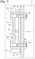
- a liquid level gauge 120 of the second embodiment has the same configuration as the liquid level gauge 20 of the first embodiment except for including a float 123, and the description of the first embodiment referring to Figs. 1 and 5 is applied to the second embodiment.
- components similar to those of the first embodiment are denoted by the identical reference signs, and the detailed description thereof will be omitted.
- Fig. 7 is a schematic cross-sectional view similar to Fig. 3 of the liquid level gauge 120 and the liquid sensor 30 of a third embodiment.
- the liquid level gauge 120 of the second embodiment includes a float 123 disposed in the hollow portion 21a of the liquid level gauge main body 21.
- the float 123 is configured to float on the hydraulic oil.
- the float 123 indicates the position of the oil level of the hydraulic oil.
- the float 123 is made of a material having low transmittance with respect to the light emitted from the light emitter 32 so as to block the light emitted from the light emitter 32.
- the second embodiment produces actions and effects similar to those of the first embodiment.
- the float 123 when the float 123 is at a level at which the light emitter 32 and the light receiver 33 are attached to the liquid level gauge 120 , the float 123 blocks the light emitted from the light emitter 32 and significantly changes the intensity of the light received by the light receiver 33, it is possible to improve the accuracy of detecting the presence or absence of the hydraulic oil.
- a liquid sensor 230 of the third embodiment has the same configuration as the liquid sensor 30 of the first embodiment except for the configuration of a thermoelectric conversion element 234, and the description of the first embodiment referring to Figs. 1 and 5 is applied to the third embodiment.
- components similar to those of the first embodiment are denoted by the identical reference signs, and the detailed description thereof will be omitted.
- Fig. 8 is a schematic cross-sectional view similar to Fig. 3 of the liquid level gauge 20 and the liquid sensor 230 of the third embodiment.
- thermoelectric conversion element 234 of the present embodiment is provided so as to be in contact with the head portion 22b of the bolt 22B.
- the third embodiment produces actions and effects similar to those of the first embodiment.
- thermoelectric conversion element 234 since the communication portion 22c of the bolt 22B is filled with the hydraulic oil, the head portion 22b of the bolt 22B made of metal tends to reach a high temperature by the heat of the hydraulic oil. According to the third embodiment, since the thermoelectric conversion element 234 is provided to be in contact with the head portion 22b of the metal bolt 22B, the thermoelectric conversion element 234 can effectively generate electric power.
- a liquid sensor 30 of the fourth embodiment has the same configuration as the liquid sensor 30 of the first embodiment except for the configuration of the light emitter 32 and the light receiver 33, and the description of the first embodiment referring to Figs. 1 and 5 is applied to the fourth embodiment.
- components similar to those of the first embodiment are denoted by the identical reference signs, and the detailed description thereof will be omitted.
- the light emitter 32 of the present embodiment includes a red light emitting diode, a green light emitting diode, and a blue light emitting diode.
- the light emitter 32 of the present embodiment can change the emission color by adjusting the amount of light emission of each of the red light emitting diode, the green light emitting diode, and the blue light emitting diode.
- the light emission manner of the light emitter 32 is determined according to contents to be notified (in the present embodiment, deterioration of hydraulic oil and decrease in hydraulic oil amount).
- the emission color changes according to the signal related to the physical quantity of the hydraulic oil.
- the light emitter 32 of the present embodiment alternately changes the emission color to, for example, green and red.
- the light emitter 32 of the present embodiment alternately changes the emission color to, for example, blue and red.
- the fourth embodiment produces actions and effects similar to those of the first embodiment.
- a liquid sensor 30 of the fifth embodiment has the same configuration as the liquid sensor 30 of the first embodiment except for not including the light emitter 32, and a detailed description thereof will be omitted.
- Fig. 9 is a schematic diagram showing a state in which the hydraulic unit 1 according to the present embodiment is disposed in a factory.
- the light receiver 33 of the present embodiment may receive , for example, light L1 from a fluorescent lamp F in the factory where the hydraulic unit 1 is installed, which passes through the hydraulic oil introduced into the liquid level gauge 20.
- the light receiver 33 of the present embodiment may receive, for example, light L2 shining into the factory through a window W of the factory where the hydraulic unit 1 is installed, which passes through the hydraulic oil in the liquid level gauge 20.
- the liquid sensor 30 is preferably configured such that the casing 31 has translucency, or configured in an L shape by eliminating a portion facing the light receiver 33.
- the fifth embodiment produces actions and effects similar to those of the first embodiment.
- the configuration of the liquid sensor 30 can be simplified.
- a liquid sensor 330 of the sixth embodiment has the same configuration as the liquid sensor 30 of the first embodiment except for being a reflective sensor, and detailed description of the same configuration will be omitted.
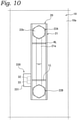
- Fig. 10 is a schematic front view showing the liquid level gauge 20 and the liquid sensor 330 according to the present embodiment.
- the liquid sensor 330 of the present embodiment is a reflective color sensor. As shown in Fig. 10 , the liquid sensor 330 of the present embodiment includes a casing 331, a light emitter 32 that emits light, and a light receiver 33 that receives light emitted from the light emitter 32, passing through a liquid level gauge main body 21 having translucency, and reflected by the hydraulic oil in the liquid level gauge main body 21. In the present embodiment, the light emitter 32 and the light receiver 33 are disposed on the same side with respect to the liquid level gauge main body 21.
- the sixth embodiment produces actions and effects similar to those of the first embodiment.
- the liquid sensor 330 since the light emitter 32 and the light receiver 33 are arranged on the same side with respect to the liquid level gauge main body 21, the liquid sensor 330 can be miniaturized as compared with a case where the light emitter and the light receiver are arranged across the liquid level gauge main body 21.
- liquid sensor 330 is a reflective sensor, it is not necessary to adjust the optical axis of the light emitter 32 and the optical axis of the light receiver 33, and it is possible to easily attach the liquid sensor 330 to the liquid level gauge 20.
- the measurement target of the liquid sensor 30 is the hydraulic oil of the hydraulic unit 1, but the measurement target of the liquid sensor 30 is not limited thereto, and another liquid such as cutting fluid or coolant liquid may be the measurement target.
- the liquid according to the present disclosure is hydraulic oil, but is not limited thereto, and may be other liquid such as cutting fluid, coolant liquid, or water.
- the liquid sensor 30 is attached to the hydraulic unit 1, but t the liquid sensor 30 may be attached to another machine or apparatus.
- the liquid sensor 30 or 230 is attached to the liquid level gauge 20, but the place where the liquid sensor is to be attached is not limited thereto, and the liquid sensor 30 or 230 has only to be attached to an object into which liquid is introduced and which has translucency.
- the light emitter 32 and the light receiver 33 are provided integrally with the casing 31, but the light emitter 32 and the light receiver 33 may be separately provided.
- the light emitting element of the liquid sensor 30 may be a monochromatic light source of red, green, blue, or another color.
- the deterioration of the liquid is determined based on the intensity of light of each color of red, green, and blue output from the liquid sensor, but the way of determining the deterioration of the liquid is not limited thereto.
- electric signals for red, green, and blue colors output from the liquid sensor may be respectively converted into cyan, yellow, and magenta colors to be used for determination of deterioration of the liquid.
- the liquid level gauge 20 being an example of the accommodation unit includes the liquid level gauge main body 21 having a substantially rectangular parallelepiped shape, but the accommodation unit is not limited thereto.
- the liquid level gauge 20 or 230 being an example of the accommodation unit may include a liquid level gauge main body with a semicircular cross-sectional shape in a cross section orthogonal to the longitudinal direction.
Landscapes
- Physics & Mathematics (AREA)
- General Physics & Mathematics (AREA)
- Fluid Mechanics (AREA)
- Chemical & Material Sciences (AREA)
- Engineering & Computer Science (AREA)
- Health & Medical Sciences (AREA)
- Life Sciences & Earth Sciences (AREA)
- Analytical Chemistry (AREA)
- Immunology (AREA)
- General Health & Medical Sciences (AREA)
- Biochemistry (AREA)
- Pathology (AREA)
- Electromagnetism (AREA)
- Thermal Sciences (AREA)
- Mechanical Engineering (AREA)
- General Engineering & Computer Science (AREA)
- Theoretical Computer Science (AREA)
- Spectroscopy & Molecular Physics (AREA)
- Mathematical Physics (AREA)
- Chemical Kinetics & Catalysis (AREA)
- General Chemical & Material Sciences (AREA)
- Oil, Petroleum & Natural Gas (AREA)
- Food Science & Technology (AREA)
- Medicinal Chemistry (AREA)
- Computer Networks & Wireless Communication (AREA)
- Investigating Or Analysing Materials By Optical Means (AREA)
- Fluid-Pressure Circuits (AREA)
- Level Indicators Using A Float (AREA)
- Measuring Fluid Pressure (AREA)
Abstract
Description
- The present disclosure relates to liquid sensors and hydraulic units.
- As a conventional liquid sensor, there is a liquid sensor which is installed in a machine and detects deterioration of lubricating oil in the machine (see Patent Literature 1).
- Patent Literature 1:
JP 2015-232582 A - However, since the conventional liquid sensor is installed in a machine by screw connection, a sealing structure is required between the liquid sensor and the machine, and there is a problem that workability of attachment work is low.
- The present disclosure proposes a liquid sensor and a hydraulic unit capable of improving workability of attachment work.
- A liquid sensor of the present disclosure includes a light receiver configured to receive light. The light receiver is attachable to an outside of an accommodation unit into which a liquid is introduced and which has translucency. The light receiver receives light that has passed through the liquid in the accommodation unit or light reflected by the liquid, and outputs a signal related to a physical quantity of the liquid.
- According to the liquid sensor of the present disclosure, since the light receiver is attachable to the outside of the accommodation unit into which the liquid to be measured is introduced, a seal structure for preventing leakage of a hydraulic oil introduced into the accommodation unit to the outside is not required between the liquid sensor and the accommodation unit, and workability of attachment work of the liquid sensor to the accommodation unit can be improved.
- The translucency according to the present disclosure is translucency with respect to light passing through the liquid.
- In one embodiment, the signal related to a physical quantity of the liquid includes a signal related to the deterioration degree of the liquid.
- In one embodiment, the signal related to a physical quantity of the liquid includes a signal related to a hue of light that has passed through the liquid and has been received by the light receiver or light that has been reflected by the liquid and has been received by the light receiver. The deterioration degree of the liquid is determined from the hue.
- In one embodiment, the signal related to a physical quantity of the liquid includes a signal related to presence or absence of the liquid in the accommodation unit.
- In one embodiment, the accommodation unit includes a float disposed inside the accommodation unit.
- In the above embodiment, when the float is at a level at which the light receiver is attached to the accommodation unit, the float blocks light and significantly changes the intensity of light received by the light receiver. This allows the accuracy of detection of the presence or absence of liquid can be improved.
- The liquid sensor according to one embodiment includes:
- a rechargeable power source configured to supply electric power to the light receiver, and
- a thermoelectric conversion element configured to generate electric power for charging the power source.
- In the above embodiment, since the liquid sensor includes a rechargeable power source that supplies power to the light receiver and a thermoelectric conversion element that generates power for charging the power source, wiring for supplying power from the outside to the liquid sensor is not required, and the liquid sensor is allowed to have a simplified wiring structure.
- The liquid sensor according to one embodiment includes a wireless transmitter configured to be supplied with electric power from the power source and to transmit the signal related to a physical quantity of the liquid of the light receiver to outside.
- According to the above embodiment, since there is no need for wiring for outputting the signal output by the light receiver to outside, the wiring structure can be simplified.
- The liquid sensor according to one embodiment includes a light emitter configured to emit light. The light emitter is attachable to the outside of the accommodation unit. The light receiver receives light emitted by the light emitter and having passed through the liquid in the accommodation unit or light emitted by the light emitter and having been reflected by the liquid in the accommodation unit.
- In one embodiment, the light emitter and the light receiver are arranged to face each other across the accommodation unit.
- In general, in a transmission type sensor, a surface of the accommodation unit has less influence on the detection accuracy than in other types of photoelectric sensors. In the above embodiment, since the liquid sensor is a transmission type sensor in which the light emitter and the light receiver are arranged to face each other across the accommodation unit, it is possible to perform reliable detection as compared with a case where a sensor of another type is used as the liquid sensor.
- In one embodiment, the light emitter and the light receiver are arranged on the same side with respect to the accommodation unit.
- In general, in a reflective sensor, since a light emitter and a light receiver are arranged on the same side of an accommodating unit, the reflective sensor is smaller than other types of photoelectric sensors. In the above embodiment, since the liquid sensor is a reflective sensor in which the light emitter and the light receiver are arranged on the same side of the accommodation unit, the liquid sensor can be made smaller than a case where a sensor of another type is used as the liquid sensor.
- The liquid sensor according to one embodiment includes a casing attachable to the outside of the accommodation unit. The light emitter and the light receiver are integrally provided in the casing.
- In the above embodiment, when the light emitter and the light receiver are integrally provided in the casing in a state where the optical axis of the light emitter and an optical axis of the light receiver coincide with each other, it is not necessary to adjust the optical axes of the light emitter and the light receiver to align the optical axes, when the liquid sensor is attached, so that workability of attachment work of the liquid sensor to the accommodation unit can be improved.
- In one embodiment, in the light emitter, a light emission manner, that is, a manner in which the light emitter emits light, is determined according to the signal related to a physical quantity of the liquid of the light receiver.
- In the above embodiment, the liquid sensor notifies a user of information on the physical quantity of the liquid by the light emission manner of the light emitter. For example, when the detection result of the liquid sensor indicates an abnormality, the light emitter of the liquid sensor emits light in a light emission manner corresponding to the abnormality. In this way, so that the liquid sensor notifies the user that the liquid sensor has detected the abnormality. Thus, the user can easily recognize the information (for example, abnormality) on the physical quantity of the liquid to be measured by visually observing the light emission manner of the liquid sensor.
- In addition, since the light emitter of the liquid sensor has both a function as a projector of a photoelectric sensor and a function of notifying the user according to the signal related to the physical quantity of the liquid, the structure of the liquid sensor can be simplified as compared with a case where these functions are separately provided.
- In one embodiment, the accommodation unit is a liquid level gauge.
- In general, a liquid level gauge is installed at a place where a user can easily visually observe the liquid level gauge. Therefore, according to the above embodiment, since the liquid sensor is attached to the liquid level gauge, the user can easily visually observe the light emitter of the liquid sensor, so that the user can easily recognize the information (for example, abnormality) on the physical quantity of the liquid to be measured.
- In one embodiment, the light emitter changes its state from off to blinking or blinking to off according to the signal related to a physical quantity of the liquid.
- In one embodiment, in the light emitter, the emission color changes according to the signal related to a physical quantity of the liquid.
- A hydraulic unit of one embodiment includes the liquid sensor described above.
-
-
Fig. 1 is a perspective view of a hydraulic unit according to a first embodiment of the present disclosure. -
Fig. 2 is a front view of a liquid sensor according to the first embodiment. -
Fig. 3 is a cross-sectional view taken along line III-III inFig. 2 . -
Fig. 4 is a cross-sectional view taken along line IV-IV inFig. 3 . -
Fig. 5 is a block diagram of the liquid sensor according to the first embodiment. -
Fig. 6 is a graph relating to a hue detected by the liquid sensor according to the first embodiment. -
Fig. 7 is a cross-sectional view similar toFig. 3 according to a second embodiment of the present disclosure. -
Fig. 8 is a cross-sectional view similar toFig. 3 according to a third embodiment of the present disclosure. -
Fig. 9 is a schematic perspective view of a hydraulic unit according to a fifth embodiment of the present disclosure. -
Fig. 10 is a perspective view of a hydraulic unit according to a sixth embodiment of the present disclosure. - Hereinafter, liquid sensors and hydraulic units according to embodiments of the present disclosure will be described with reference to the accompanying drawings.
-
Fig. 1 is a perspective view of ahydraulic unit 1 according to a first embodiment of the present disclosure. Thehydraulic unit 1 according to the present embodiment supplies hydraulic oil to an external apparatus such as a machine tool. - Referring to
Fig. 1 , thehydraulic unit 1 includes ahydraulic oil tank 10 that accommodates hydraulic oil, and amount 11 attached to an upper portion of thehydraulic oil tank 10. Thehydraulic unit 1 includes a hydraulic pump (not shown), a motor (not shown) that drives the hydraulic pump, an oil cooler 12 that cools hydraulic oil discharged from the hydraulic pump, and acontroller 13 that controls the motor. The hydraulic pump, the motor, theoil cooler 12, and thecontroller 13 are mounted on themount 11, and thehydraulic oil tank 10 is disposed below themount 11. In addition, thehydraulic unit 1 includes a coolingfan 14 that supplies cooling air to the motor and theoil cooler 12. Thehydraulic unit 1 is herein described by way of example only; and not limited to the above-described structure. - A
liquid level gauge 20 for externally checking the amount of the hydraulic oil accommodated in thehydraulic oil tank 10 is attached to ametal side surface 10a of thehydraulic oil tank 10. Since theliquid level gauge 20 is attached to theside surface 10a of thehydraulic oil tank 10, a user can easily visually check the amount of the hydraulic oil accommodated in thehydraulic oil tank 10. In addition, aliquid sensor 30 that measures a physical quantity (hue in the present embodiment) of liquid (hydraulic oil in the present embodiment) is attached to the outside of theliquid level gauge 20. -
Fig. 2 is a schematic front view showing theliquid level gauge 20 and theliquid sensor 30 according to the present embodiment.Fig. 3 is a schematic cross-sectional view taken along line III-III inFig. 2 . InFig. 3 , illustration of a detailed structure of the inside of theliquid sensor 30 is omitted. InFigs. 2 and3 , the same components as inFig. 1 are denoted by the same reference signs as inFig. 1 . - Referring to
Figs. 2 and3 , theliquid level gauge 20 of the present embodiment is an oil level gauge for checking the oil level of the hydraulic oil accommodated in thehydraulic oil tank 10. Theliquid level gauge 20 of the present embodiment includes a liquid level gaugemain body 21 made of a transparent acrylic resin and twobolts main body 21 to thehydraulic oil tank 10. Theliquid level gauge 20 according to the present embodiment is an example of a translucent accommodation unit into which the liquid (hydraulic oil in the present embodiment) according to the present disclosure is introduced. - The liquid level gauge
main body 21 of the present embodiment has a substantially rectangular parallelepiped shape, and is attached to thehydraulic oil tank 10 such that the liquid level gaugemain body 21 has a longitudinal direction that extends along the vertical direction. The liquid level gaugemain body 21 is hollow. Specifically, the liquid level gaugemain body 21 includes ahollow portion 21a being a space extending in the longitudinal direction inside the liquid level gaugemain body 21. The hydraulic oil is introduced into thehollow portion 21a of the liquid level gaugemain body 21 according to the amount of the hydraulic oil accommodated in thehydraulic oil tank 10. The user can check the amount of the hydraulic oil accommodated in thehydraulic oil tank 10 by visually observing the oil level of the hydraulic oil in thehollow portion 21a of the liquid level gaugemain body 21. The liquid level gaugemain body 21 is provided with an upper limit line HL indicating the upper limit of an allowable range of the oil level of the hydraulic oil and a lower limit line LL indicating the lower limit of the allowable range of the oil level of the hydraulic oil. - The
bolts Fig. 3 , each of thebolts communication portion 22c extending in the axial direction from atip portion 22a toward ahead portion 22b of the bolt. Thecommunication portion 22c is open in the radial direction at an axial end portions on thehead portion 22b side of each of thebolts bolts communication portions 22c of thebolts hydraulic oil tank 10 to thehollow portion 21a of the liquid level gaugemain body 21 in a state where thebolts main body 21 to thehydraulic oil tank 10. In other words, the internal space of thehydraulic oil tank 10, thehollow portion 21a of the liquid level gaugemain body 21, and thecommunication portion 22c of thebolts - In the state shown in
Fig. 3 , thecommunication portion 22c of thebolt 22B opens at thetip portion 22a into an area where the hydraulic oil accumulated in thehydraulic oil tank 10 exists. At this time, the hydraulic oil is introduced from thehydraulic oil tank 10 into thehollow portion 21a of the liquid level gaugemain body 21 through thecommunication portion 22c of thebolt 22B. In addition, thecommunication portion 22c of thebolt 22B is filled with hydraulic oil. - As shown in
Fig. 3 , the oil level of the hydraulic oil introduced into the liquid level gaugemain body 21 coincides with the oil level of the hydraulic oil accommodated in thehydraulic oil tank 10. Thus, the user can check the amount of the hydraulic oil accommodated in thehydraulic oil tank 10 by visually observing the oil level of the hydraulic oil in thehollow portion 21a of the liquid level gaugemain body 21. - The
liquid sensor 30 of the present embodiment is a photoelectric sensor for detecting the degree of deterioration of the hydraulic oil accommodated in thehydraulic oil tank 10 and the presence or absence of the hydraulic oil. More specifically, theliquid sensor 30 is a transmissive color sensor. As shown inFig. 2 , theliquid sensor 30 of the present embodiment includes aU-shaped casing 31, alight emitter 32 that emits light, and alight receiver 33 that receives the light emitted from thelight emitter 32. Thelight emitter 32 and thelight receiver 33 are provided integrally with thecasing 31 so as to face each other. Specifically, thelight emitter 32 and thelight receiver 33 are provided integrally with thecasing 31 so that the optical axis of thelight emitter 32 and the optical axis of thelight receiver 33 coincide with each other. - The
liquid sensor 30 is attached to the liquid level gaugemain body 21 such that thelight emitter 32 and thelight receiver 33 face each other across the liquid level gaugemain body 21. In addition, theliquid sensor 30 is attached to theliquid level gauge 20 such that the height positions of thelight emitter 32 and thelight receiver 33 overlap with the height position of the lower limit line LL of the liquid level gaugemain body 21. Theliquid sensor 30 detects the presence or absence of hydraulic oil below the lower limit line LL of the liquid level gaugemain body 21. - A packing (not shown) is provided between the casing 31 of the
liquid sensor 30 and the liquid level gaugemain body 21 of the present embodiment. This packing makes thecasing 31 and the liquid level gaugemain body 21 water-resistant and dust-resistant, prevents external light from entering the liquid level gaugemain body 21, and brings thecasing 31 into close contact with the liquid level gaugemain body 21 so that thecasing 31 is held by the liquid level gaugemain body 21. - The
light emitter 32 of the present embodiment includes a light emitting element for emitting light and a drive circuit for driving the light emitting element. The light emitting element of the present embodiment is a white light emitting diode. In other words, thelight emitter 32 of the present embodiment emits white light. - The
light receiver 33 of the present embodiment includes a light receiving element that converts the intensity of light into an electric signal, an amplifier circuit that amplifies the electric signal output from the light receiving element, and an A/D conversion circuit that converts the analog electric signal amplified by the amplifier circuit into a digital electric signal. The light receiving element of the present embodiment is an RGB color sensor, and can detect the electric signal converted from received visible light separately for each color of red, green, and blue. - As shown in
Fig. 3 , theliquid sensor 30 of the present embodiment further includes athermoelectric conversion element 34 that converts heat into electric power. Thethermoelectric conversion element 34 of the present embodiment is provided so as to be in contact with theside surface 10a of thehydraulic oil tank 10. Theside surface 10a of thehydraulic oil tank 10 is likely to have a high temperature because the hydraulic oil accommodated in thehydraulic oil tank 10 has a high temperature due to heat generation from a sliding portion of the machine tool or the like. Thethermoelectric conversion element 34 generates power using a temperature difference between the temperature of theside surface 10a of thehydraulic oil tank 10 and the temperature of the air around theliquid sensor 30. -
Fig. 4 is a schematic cross-sectional view taken along line IV-IV inFig. 3 . InFig. 4 , illustration of a detailed structure of the inside of theliquid sensor 30 is omitted. InFig. 4 , the same components as inFig. 1 to 3 are denoted by the same reference signs as inFigs. 1 to 3 . - Referring to
Fig. 4 , thehollow portion 21a of the liquid level gaugemain body 21 has a circular cross-sectional shape in the cross section shown inFig. 4 . - As shown in
Fig. 4 , the optical axis XI of thelight emitter 32 and the optical axis X2 of thelight receiver 33 coincide with each other. In addition, the optical axis XI of thelight emitter 32 and the optical axis X2 of thelight receiver 33 extend to pass through the center C of thehollow portion 21a of the liquid level gaugemain body 21. Here, the optical axis XI of thelight emitter 32 and the optical axis X2 of thelight receiver 33 do not necessarily need to pass through the center C of thehollow portion 21a. It is preferable that the shortest distance from the optical axis XI of thelight emitter 32 and the optical axis X2 of thelight receiver 33 to the center C of thehollow portion 21a is 5 mm or less. -
Fig. 5 is a block diagram of theliquid sensor 30 of the present embodiment. InFig. 5 , the same components as inFigs. 1 to 3 are denoted by the same reference signs as inFigs. 1 to 3 . - Referring to
Fig. 5 , theliquid sensor 30 of the present embodiment includes awireless transmitter 35 that wirelessly transmits a signal to an external apparatus, awireless receiver 36 that wirelessly receives a signal from an external apparatus, and acontrol device 37. - The
wireless transmitter 35 communicates with the controller 13 (shown inFig. 1 ) of thehydraulic unit 1, and transmits an electric signal output from thelight receiver 33 to thecontroller 13 of thehydraulic unit 1. Thewireless receiver 36 communicates with thecontroller 13 of thehydraulic unit 1, and receives an electric signal such as a control signal from thecontroller 13 of thehydraulic unit 1. Thecontrol device 37 controls thelight emitter 32, thelight receiver 33, thewireless transmitter 35, and thewireless receiver 36. - The
liquid sensor 30 further includes apower source 38 for supplying (see a two-dot chain line inFig. 5 ) power to each of thelight emitter 32, thelight receiver 33, thewireless transmitter 35, thewireless receiver 36, and thecontrol device 37. Thepower source 38 of the present embodiment includes a rechargeable battery. In addition, thepower source 38 is electrically connected to thethermoelectric conversion element 34. Thethermoelectric conversion element 34 generates electric power for charging thepower source 38 using a temperature difference between the hydraulic oil tank 10 (shown inFig. 1 ) and air around theliquid sensor 30. - The
light emitter 32 of theliquid sensor 30 according to the present embodiment emits white light from the light emitting element with the power supplied from thepower source 38. Thelight receiver 33 of theliquid sensor 30 receives light emitted from thelight emitter 32 and having passed through the liquid level gaugemain body 21 and the hydraulic oil in the liquid level gaugemain body 21. Theliquid sensor 30 transmits the light intensity of each of colors of red, green, and blue of light received by the light receiving element of thelight receiver 33 to the controller 13 (shown inFig. 1 ) of thehydraulic unit 1 via thewireless transmitter 35 as an electric signal. Since each of the red, green, and blue lights received by thelight receiver 33 is light having a wavelength that was not absorbed by the hydraulic oil in thelevel gauge 20, it is possible to detect the hue of the hydraulic oil in theliquid level gauge 20 from the intensity of those lights transmitted by thelight sensor 30. In other words, thelight receiver 33 of theliquid sensor 30 according to the present embodiment converts the hue being an example of the physical quantity of the hydraulic oil into an electric signal and outputs the electric signal. In short, theliquid sensor 30 according to the present disclosure outputs a signal related to a physical quantity (hue in the present embodiment) of liquid (hydraulic oil in the present embodiment). Here, the translucency of theliquid level gauge 20 according to the present disclosure is translucency with respect to light (white light in the present embodiment) emitted by thelight emitter 32. - The controller 13 (shown in
Fig. 1 ) of thehydraulic unit 1 of the present embodiment determines the degree of deterioration of the hydraulic oil and the presence or absence of the hydraulic oil based on the signal related to the hue of the hydraulic oil output from theliquid sensor 30. In other words, theliquid sensor 30 of the present embodiment outputs a signal related to the degree of deterioration of the hydraulic oil and a signal related to the presence or absence of the hydraulic oil. The degree of deterioration of the hydraulic oil and the presence or absence of the hydraulic oil are examples of physical quantities of the liquid (hydraulic oil in the present embodiment) according to the present disclosure. -
Fig. 6 is an example of a calibration curve related to the hue used to determine the degree of deterioration of the hydraulic oil and the presence or absence of the hydraulic oil in the present embodiment.Fig. 6 shows the intensity [arbitrary scale] of light for each color of red, green, and blue for air, water, and the hydraulic oil having different hues. In the present embodiment, the hue of the hydraulic oil is represented using an ASTM color measured conforming to ASTM D1500. The ASTM color numerically indicates the hue of the hydraulic oil by a color scale ranging from 0.5 of a light color to 8.0 of a dark color in increments of 0.5. The ASTM color is an index of the degree of deterioration of the hydraulic oil, and indicates that the larger the value of the ASTM color, the more the hydraulic oil is deteriorated. In the present embodiment, the calibration curve (or calibration table) as shown inFig. 6 is stored in the controller 13 (shown inFig. 1 ) of thehydraulic unit 1. - In the present embodiment, the controller 13 (shown in
Fig. 1 ) of thehydraulic unit 1 determines the degree of deterioration of the hydraulic oil and the presence or absence of the hydraulic oil using the electric signals for each color of the red, green, and blue output from theliquid sensor 30 and the calibration curve shown inFig. 6 . Specifically, thecontroller 13 of thehydraulic unit 1 compares the intensity (hereinafter, referred to as a measurement result of the liquid sensor 30) of light for each color of red, green, and blue for the hydraulic oil to be measured, which are calculated from the output voltage of thelight receiver 33 of theliquid sensor 30, with the calibration curve shown inFig. 6 . The degree of deterioration of the hydraulic oil is calculated from the measurement result of theliquid sensor 30 using the calibration curve for the ASTM color inFig. 6 . In addition, the presence or absence of the hydraulic oil is determined based on whether or not the measurement result of theliquid sensor 30 indicates air by comparing the measurement result of theliquid sensor 30 with the calibration curve inFig. 6 . If determining that the measurement result of theliquid sensor 30 indicates air, thecontroller 13 of thehydraulic unit 1 determines that there is no hydraulic oil at the detection position (in the present embodiment, below the lower limit line LL) of theliquid sensor 30. - When the temperature in a factory where the
hydraulic unit 1 is installed is low, dew condensation occurs on the inner surface of the liquid level gaugemain body 21 that defines thehollow portion 21a, and theliquid sensor 30 may make an erroneous determination due to irregular reflection caused by the dew condensation or moisture mixing into the hydraulic oil. Therefore, the measurement using theliquid sensor 30 described above is preferably performed after it is determined that thehydraulic unit 1 is in a stable operation state by referring to the operation time or the oil temperature rise after the start of thehydraulic unit 1. - The
liquid sensor 30 notifies the user of information on the physical quantity of the liquid (for example, abnormality) based on the light emission manner of thelight emitter 32. Specifically, theliquid sensor 30 notifies the user of the abnormalities related to the deterioration degree of the hydraulic oil and the presence or absence of the hydraulic oil based on the light emission manner of thelight emitter 32. - In the present embodiment, when the controller 13 (shown in
Fig. 1 ) of thehydraulic unit 1 determines that the hydraulic oil has deteriorated more than the predetermined deterioration degree, or determines that there is no hydraulic oil at the detection position, thecontroller 13 of thehydraulic unit 1 transmits a control signal for controlling thelight emitter 32 to theliquid sensor 30. When thewireless receiver 36 of theliquid sensor 30 receives the control signal from thecontroller 13 of thehydraulic unit 1, thecontrol device 37 controls thelight emitter 32 so that the light emission manner of thelight emitter 32 changes according to contents to be notified. Thus, theliquid sensor 30 notifies the user of the abnormality (deterioration in hydraulic oil or decrease in hydraulic oil amount). The predetermined deterioration degree is, for example, a deterioration degree when the ASTM color becomes dark to 2.5 or more. - The light emission manner of the
light emitter 32 is determined according to contents to be notified (in the present embodiment, deterioration of hydraulic oil and decrease in hydraulic oil amount). In other words, in thelight emitter 32 of the present embodiment, the light emission manner is determined according to the signal related to the physical quantity of the hydraulic oil. When the deterioration of the hydraulic oil is notified, thelight emitter 32 of the present embodiment blinks. In other words, when the deterioration of the hydraulic oil is notified, the light emission manner of thelight emitter 32 changes from off to blinking. In addition, when the decrease in the hydraulic oil amount is notified, thelight emitter 32 of the present embodiment is turned on. In other words, when the decrease in the hydraulic oil amount is notified, the light emission manner of thelight emitter 32 changes from off to on. For example, the light emission manner of thelight emitter 32 may change a blinking pattern such as a blinking interval and a blinking speed according to contents to be notified. - The controller 13 (shown in
Fig. 1 ) of thehydraulic unit 1 may display a numerical value (for example, ASTM color value) or a color in accordance with the level of the deterioration degree of the hydraulic oil on adisplay unit 13a provided in thecontroller 13, a display unit (not shown) provided in an external apparatus to which thehydraulic unit 1 supplies the hydraulic oil, or the like. Thus, it is possible to alert the user to replace the hydraulic oil before the hydraulic oil needs to be replaced. - In addition, the controller 13 (shown in
Fig. 1 ) of thehydraulic unit 1 may notify the user of deterioration of the hydraulic oil before the hydraulic oil needs to be replaced. For example, thecontroller 13 of thehydraulic unit 1 may notify the user of the deterioration of the hydraulic oil by causing thelight emitter 32 to emit light even before the ASTM color becomes dark to 2.5 or more, for example. In this case, as the deterioration of the hydraulic oil progresses, the frequency of light emission of thelight emitter 32 may increase. - According to the
liquid sensor 30 of the present disclosure, since thelight emitter 32 and thelight receiver 33 are attached to the outside of theliquid level gauge 20 into which the hydraulic oil to be measured is introduced, a seal structure for preventing leakage of the hydraulic oil introduced into theliquid level gauge 20 to the outside is not required between theliquid sensor 30 and theliquid level gauge 20, and workability of attachment work of theliquid sensor 30 to theliquid level gauge 20 can be improved. - In general, in the transmission type sensor, the surface of the
liquid level gauge 20 has less influence on the detection accuracy than in other types of photoelectric sensors. In the above embodiment, since theliquid sensor 30 is a transmission type sensor, it is possible to perform reliable detection as compared with a case where a sensor of another type is used as theliquid sensor 30. - In the above embodiment, since the
light emitter 32 and thelight receiver 33 are integrally provided in thecasing 31 in a state where the optical axis of thelight emitter 32 and the optical axis of thelight receiver 33 are made to coincide with each other, it is not necessary to adjust the optical axes of the light emitter and the light receiver when theliquid sensor 30 is attached, so that workability of attachment work of theliquid sensor 30 to theliquid level gauge 20 can be improved. - According to the
liquid sensor 30 of the present disclosure, since theliquid sensor 30 includes therechargeable power source 38 that supplies power to thelight emitter 32 and thelight receiver 33 and thethermoelectric conversion element 34 that generates power for charging thepower source 38, wiring for supplying power from the outside to theliquid sensor 30 is not required, and the wiring structure can be simplified. - According to the above embodiment, since the detection result of the
liquid sensor 30 is transmitted to thecontroller 13 of thehydraulic unit 1 via thewireless transmitter 35, there is no need for wiring for outputting the signal output from thelight receiver 33 to the outside, and the wiring structure can be simplified. - In the above embodiment, the
liquid sensor 30 notifies the user of information on the physical quantity of the hydraulic oil by the light emission manner of thelight emitter 32. For example, when the detection result of theliquid sensor 30 indicates an abnormality, thelight emitter 32 of theliquid sensor 30 emits light in a light emission manner corresponding to the abnormality, whereby theliquid sensor 30 notifies the user that theliquid sensor 30 has detected the abnormality. Thus, the user can easily recognize the information (for example, abnormality) on the physical quantity of the hydraulic oil by visually observing the light emission manner of theliquid sensor 30. - In addition, since the
light emitter 32 of theliquid sensor 30 has both a function as a projector of a photoelectric sensor and a function of notifying the user according to the signal related to the physical quantity of the hydraulic oil, the structure of theliquid sensor 30 can be simplified as compared with a case where these functions are separately provided. - In general, a liquid level gauge is installed at a place where a user can easily visually observe. Therefore, according to the above embodiment, since the
liquid sensor 30 is attached to the liquid level gauge, the user can easily visually observe thelight emitter 32 of theliquid sensor 30, so that the user can easily recognize the information (for example, abnormality) on the physical quantity of the liquid to be measured. - In the present embodiment, the
controller 13 of thehydraulic unit 1 determines the degree of deterioration of the hydraulic oil and the presence or absence of the hydraulic oil. However, thecontrol device 37 of theliquid sensor 30 may determine the degree of deterioration of the hydraulic oil and the presence or absence of the hydraulic oil. In this case, theliquid sensor 30 does not need to include thewireless transmitter 35 and thewireless receiver 36. - A
liquid level gauge 120 of the second embodiment has the same configuration as theliquid level gauge 20 of the first embodiment except for including afloat 123, and the description of the first embodiment referring toFigs. 1 and5 is applied to the second embodiment. In the second embodiment, components similar to those of the first embodiment are denoted by the identical reference signs, and the detailed description thereof will be omitted. -
Fig. 7 is a schematic cross-sectional view similar toFig. 3 of theliquid level gauge 120 and theliquid sensor 30 of a third embodiment. - Referring to
Fig. 7 , theliquid level gauge 120 of the second embodiment includes afloat 123 disposed in thehollow portion 21a of the liquid level gaugemain body 21. Thefloat 123 is configured to float on the hydraulic oil. Thus, thefloat 123 indicates the position of the oil level of the hydraulic oil. Thefloat 123 is made of a material having low transmittance with respect to the light emitted from thelight emitter 32 so as to block the light emitted from thelight emitter 32. - The second embodiment produces actions and effects similar to those of the first embodiment.
- In addition, according to the second embodiment, when the
float 123 is at a level at which thelight emitter 32 and thelight receiver 33 are attached to theliquid level gauge 120 , thefloat 123 blocks the light emitted from thelight emitter 32 and significantly changes the intensity of the light received by thelight receiver 33, it is possible to improve the accuracy of detecting the presence or absence of the hydraulic oil. - A
liquid sensor 230 of the third embodiment has the same configuration as theliquid sensor 30 of the first embodiment except for the configuration of a thermoelectric conversion element 234, and the description of the first embodiment referring toFigs. 1 and5 is applied to the third embodiment. In the third embodiment, components similar to those of the first embodiment are denoted by the identical reference signs, and the detailed description thereof will be omitted. -
Fig. 8 is a schematic cross-sectional view similar toFig. 3 of theliquid level gauge 20 and theliquid sensor 230 of the third embodiment. - Referring to
Fig. 8 , the thermoelectric conversion element 234 of the present embodiment is provided so as to be in contact with thehead portion 22b of thebolt 22B. - The third embodiment produces actions and effects similar to those of the first embodiment.
- In addition, since the
communication portion 22c of thebolt 22B is filled with the hydraulic oil, thehead portion 22b of thebolt 22B made of metal tends to reach a high temperature by the heat of the hydraulic oil. According to the third embodiment, since the thermoelectric conversion element 234 is provided to be in contact with thehead portion 22b of themetal bolt 22B, the thermoelectric conversion element 234 can effectively generate electric power. - A
liquid sensor 30 of the fourth embodiment has the same configuration as theliquid sensor 30 of the first embodiment except for the configuration of thelight emitter 32 and thelight receiver 33, and the description of the first embodiment referring toFigs. 1 and5 is applied to the fourth embodiment. In the fourth embodiment, components similar to those of the first embodiment are denoted by the identical reference signs, and the detailed description thereof will be omitted. - The
light emitter 32 of the present embodiment includes a red light emitting diode, a green light emitting diode, and a blue light emitting diode. Thelight emitter 32 of the present embodiment can change the emission color by adjusting the amount of light emission of each of the red light emitting diode, the green light emitting diode, and the blue light emitting diode. - The light emission manner of the
light emitter 32 is determined according to contents to be notified (in the present embodiment, deterioration of hydraulic oil and decrease in hydraulic oil amount). In thelight emitter 32 of the present embodiment, the emission color changes according to the signal related to the physical quantity of the hydraulic oil. When the deterioration of the hydraulic oil is notified, thelight emitter 32 of the present embodiment alternately changes the emission color to, for example, green and red. In addition, when the decrease in the hydraulic oil amount is notified, thelight emitter 32 of the present embodiment alternately changes the emission color to, for example, blue and red. - The fourth embodiment produces actions and effects similar to those of the first embodiment.
- A
liquid sensor 30 of the fifth embodiment has the same configuration as theliquid sensor 30 of the first embodiment except for not including thelight emitter 32, and a detailed description thereof will be omitted.Fig. 9 is a schematic diagram showing a state in which thehydraulic unit 1 according to the present embodiment is disposed in a factory. - Referring to
Fig. 9 , thelight receiver 33 of the present embodiment may receive , for example, light L1 from a fluorescent lamp F in the factory where thehydraulic unit 1 is installed, which passes through the hydraulic oil introduced into theliquid level gauge 20. Alternatively, thelight receiver 33 of the present embodiment may receive, for example, light L2 shining into the factory through a window W of the factory where thehydraulic unit 1 is installed, which passes through the hydraulic oil in theliquid level gauge 20. In this case, theliquid sensor 30 is preferably configured such that thecasing 31 has translucency, or configured in an L shape by eliminating a portion facing thelight receiver 33. - The fifth embodiment produces actions and effects similar to those of the first embodiment.
- In addition, according to the fifth embodiment, since it is not necessary to provide the light emitter, the configuration of the
liquid sensor 30 can be simplified. - A
liquid sensor 330 of the sixth embodiment has the same configuration as theliquid sensor 30 of the first embodiment except for being a reflective sensor, and detailed description of the same configuration will be omitted.Fig. 10 is a schematic front view showing theliquid level gauge 20 and theliquid sensor 330 according to the present embodiment. - The
liquid sensor 330 of the present embodiment is a reflective color sensor. As shown inFig. 10 , theliquid sensor 330 of the present embodiment includes acasing 331, alight emitter 32 that emits light, and alight receiver 33 that receives light emitted from thelight emitter 32, passing through a liquid level gaugemain body 21 having translucency, and reflected by the hydraulic oil in the liquid level gaugemain body 21. In the present embodiment, thelight emitter 32 and thelight receiver 33 are disposed on the same side with respect to the liquid level gaugemain body 21. - The sixth embodiment produces actions and effects similar to those of the first embodiment.
- According to the
liquid sensor 330, since thelight emitter 32 and thelight receiver 33 are arranged on the same side with respect to the liquid level gaugemain body 21, theliquid sensor 330 can be miniaturized as compared with a case where the light emitter and the light receiver are arranged across the liquid level gaugemain body 21. - In addition, since the
liquid sensor 330 is a reflective sensor, it is not necessary to adjust the optical axis of thelight emitter 32 and the optical axis of thelight receiver 33, and it is possible to easily attach theliquid sensor 330 to theliquid level gauge 20. - Although the embodiments have been described above, it will be understood that various changes in form and details can be made without departing from the spirit and scope of the claims.
- For example, in the first to sixth embodiments, the measurement target of the
liquid sensor 30 is the hydraulic oil of thehydraulic unit 1, but the measurement target of theliquid sensor 30 is not limited thereto, and another liquid such as cutting fluid or coolant liquid may be the measurement target. In other words, in the first to sixth embodiments, the liquid according to the present disclosure is hydraulic oil, but is not limited thereto, and may be other liquid such as cutting fluid, coolant liquid, or water. - In the first to sixth embodiments, the
liquid sensor 30 is attached to thehydraulic unit 1, but t theliquid sensor 30 may be attached to another machine or apparatus. - In the first to sixth embodiments, the
liquid sensor liquid level gauge 20, but the place where the liquid sensor is to be attached is not limited thereto, and theliquid sensor - In the first to sixth embodiments, the
light emitter 32 and thelight receiver 33 are provided integrally with thecasing 31, but thelight emitter 32 and thelight receiver 33 may be separately provided. - The light emitting element of the
liquid sensor 30 may be a monochromatic light source of red, green, blue, or another color. - In the first to sixth embodiments, the deterioration of the liquid (hydraulic oil in the embodiment) is determined based on the intensity of light of each color of red, green, and blue output from the liquid sensor, but the way of determining the deterioration of the liquid is not limited thereto. For example, electric signals for red, green, and blue colors output from the liquid sensor may be respectively converted into cyan, yellow, and magenta colors to be used for determination of deterioration of the liquid.
- In addition, in the first to sixth embodiments, the
liquid level gauge 20 being an example of the accommodation unit includes the liquid level gaugemain body 21 having a substantially rectangular parallelepiped shape, but the accommodation unit is not limited thereto. For example, theliquid level gauge -
- 1
- Hydraulic unit
- 10
- Hydraulic oil tank
- 10a
- Side surface
- 11
- Stand
- 12
- Oil cooler
- 13
- Controller
- 14
- Cooling fan
- 20
- Liquid level gauge (accommodation unit)
- 21
- Liquid level gauge main body
- 21a
- Hollow portion
- 22A, 22B
- Bolt
- 22a
- Tip portion
- 22b
- Head portion
- 22c
- Communication portion
- 30
- Liquid sensor
- 31
- Casing
- 32
- Light emitter
- 33
- Light receiver
- 34
- Thermoelectric conversion element
- 35
- Wireless transmitter
- 36
- Wireless receiver
- 37
- Control device
- 38
- Power source
- 120
- Liquid level gauge (accommodation unit)
- 123
- Float
- 230
- Liquid sensor
- 234
- Thermoelectric conversion element
- HL
- Upper limit line
- LL
- Lower limit line
Claims (16)
- A liquid sensor (30, 230, 330) comprising:a light receiver (33) configured to receive light,wherein the light receiver (33) is attachable to an outside of an accommodation unit (20, 120) into which a liquid is introduced and which has translucency, andthe light receiver (33) receives light that has passed through the liquid in the accommodation unit (20, 120) or light reflected by the liquid, and outputs a signal related to a physical quantity of the liquid.
- The liquid sensor (30, 230, 330) according to claim 1, wherein the signal related to the physical quantity of the liquid includes a signal related to a deterioration degree of the liquid.
- The liquid sensor (30, 230, 330) according to claim 2, whereinthe signal related to the physical quantity of the liquid includes a signal related to a hue of light that has passed through the liquid and has been received by the light receiver (33) or light that has been reflected by the liquid and has been received by the light receiver (33), andthe deterioration degree of the liquid is determined from the hue.
- The liquid sensor (30, 230, 330) according to any one of claims 1 to 3, wherein the signal related to the physical quantity of the liquid includes a signal related to presence or absence of the liquid in the accommodation unit (20, 120).
- The liquid sensor (30, 230, 330) according to claim 4, wherein the accommodation unit (120) includes a float (123) disposed inside the accommodation unit (120).
- The liquid sensor (30, 230, 330) according to any one of claims 1 to 5, further comprising:a power source (38) that is rechargeable and configured to supply electric power to the light receiver (33), anda thermoelectric conversion element (34) configured to generate electric power for charging the power source (38).
- The liquid sensor (30, 230, 330) according to claim 6, further comprising a wireless transmitter (35) configured to be supplied with electric power from the power source (38) and to transmit the signal related to a physical quantity of the liquid of the light receiver (33) to outside.
- The liquid sensor (30, 230, 330) according to any one of claims 1 to 7,further comprising a light emitter (32) configured to emit light,wherein the light emitter (32) is attachable to the outside of the accommodation unit (20, 120), andthe light receiver (33) receives light emitted by the light emitter (32) and having passed through the liquid in the accommodation unit (20, 120) or light emitted by the light emitter (32) and having been reflected by the liquid in the accommodation unit (20, 120).
- The liquid sensor (30, 230) according to claim 8, wherein the light emitter (32) and the light receiver (33) are arranged to face each other across the accommodation unit (20, 120).
- The liquid sensor (330) according to claim 8, wherein the light emitter (32) and the light receiver (33) are arranged on a same side of the accommodation unit (20).
- The liquid sensor (30, 230, 330) according to any one of claims 8 to 10,further comprising a casing (31) attachable to the outside of the accommodation unit (20, 120),wherein the light emitter (32) and the light receiver (33) are integrally provided in the casing (31).
- The liquid sensor (30, 230, 330) according to any one of claims 8 to 11, wherein
in the light emitter (32), a light emission manner in which the light emitter (32) emits light is determined according to the signal related to a physical quantity of the liquid of the light receiver (33). - The liquid sensor (30, 230, 330) according to claim 12, wherein the accommodation unit (20, 120) is a liquid level gauge (20, 120).
- The liquid sensor (30, 230, 330) according to claim 12 or 13, wherein the light emitter (32) changes its state from off to blinking or from blinking to off according to the signal related to a physical quantity of the liquid.
- The liquid sensor (30, 230, 330) according to any one of claims 12 to 14, wherein in the light emitter (32), an emission color changes according to the signal related to a physical quantity of the liquid.
- A hydraulic unit (1) comprising the liquid sensor (30, 230, 330) according to any one of claims 1 to 15.
Applications Claiming Priority (4)
| Application Number | Priority Date | Filing Date | Title |
|---|---|---|---|
| JP2019092977 | 2019-05-16 | ||
| JP2019092976 | 2019-05-16 | ||
| JP2019092979 | 2019-05-16 | ||
| PCT/JP2020/019288 WO2020230855A1 (en) | 2019-05-16 | 2020-05-14 | Liquid sensor and hydraulic unit |
Publications (3)
| Publication Number | Publication Date |
|---|---|
| EP3971539A1 true EP3971539A1 (en) | 2022-03-23 |
| EP3971539A4 EP3971539A4 (en) | 2023-01-11 |
| EP3971539B1 EP3971539B1 (en) | 2025-12-03 |
Family
ID=73290050
Family Applications (1)
| Application Number | Title | Priority Date | Filing Date |
|---|---|---|---|
| EP20805503.8A Active EP3971539B1 (en) | 2019-05-16 | 2020-05-14 | Liquid sensor and hydraulic unit |
Country Status (7)
| Country | Link |
|---|---|
| US (1) | US12590943B2 (en) |
| EP (1) | EP3971539B1 (en) |
| JP (1) | JP6954405B2 (en) |
| CN (1) | CN113841039A (en) |
| ES (1) | ES3057752T3 (en) |
| TW (1) | TWI764150B (en) |
| WO (1) | WO2020230855A1 (en) |
Families Citing this family (4)
| Publication number | Priority date | Publication date | Assignee | Title |
|---|---|---|---|---|
| CN117705224A (en) * | 2022-09-09 | 2024-03-15 | 长鑫存储技术有限公司 | Device, system and method for monitoring light resistance |
| JP2024072170A (en) * | 2022-11-15 | 2024-05-27 | 株式会社日立製作所 | Oil diagnostic method and oil diagnostic system |
| FR3138945A1 (en) * | 2022-12-16 | 2024-02-23 | Sagemcom Energy & Telecom Sas | Method and device for monitoring the level of a liquid |
| WO2025033209A1 (en) * | 2023-08-07 | 2025-02-13 | Eneos株式会社 | Measuring device and diagnostic system |
Family Cites Families (76)
| Publication number | Priority date | Publication date | Assignee | Title |
|---|---|---|---|---|
| US2295366A (en) * | 1938-09-27 | 1942-09-08 | Coca Cola Co | Inspection device |
| JPS506387Y1 (en) * | 1969-12-09 | 1975-02-24 | ||
| US3710111A (en) * | 1970-12-28 | 1973-01-09 | Dreyfus E | Dynamically calibrated oil content meter |
| US3892485A (en) * | 1974-05-06 | 1975-07-01 | Gen Electric | Monitoring apparatus for measuring particles suspended in liquid and for measuring the opacity of the liquid |
| US4014010A (en) * | 1975-08-01 | 1977-03-22 | Walter Joseph Jinotti | Fluid-dispensing apparatus having level control and alarm means |
| US4306525A (en) * | 1980-05-12 | 1981-12-22 | General Motors Corporation | Engine oil indicator |
| US4570069A (en) * | 1982-12-30 | 1986-02-11 | Gager Dennis J | On-board electronic oil contamination detector for vehicle engines |
| DE3341265A1 (en) * | 1983-11-15 | 1985-05-23 | Phönix Armaturen-Werke Bregel GmbH, 6000 Frankfurt | MEASURING DEVICE |
| JPS60181513A (en) * | 1984-02-28 | 1985-09-17 | Sanyo Electric Co Ltd | Combustion device for liquid fuel |
| JPH0629534B2 (en) * | 1984-07-27 | 1994-04-20 | 三信工業株式会社 | Lubricating oil supply state detection device in internal combustion engine |
| US4649281A (en) * | 1985-07-02 | 1987-03-10 | The United States Of America As Represented By The Secretary Of The Navy | Oil content monitor/control system |
| US4920336A (en) * | 1988-11-22 | 1990-04-24 | Fisher Scientific Company | Method and apparatus for monitoring the level of the contents in a container |
| US5175438A (en) * | 1989-11-10 | 1992-12-29 | Nikuni Machinery Industrial Co., Ltd. | Method of distinguishing particles in fluid and apparatus for the same using dual wavelength reflectivity ratio sensing |
| US5049742A (en) * | 1989-11-16 | 1991-09-17 | Kyodo Oil Technical Research Co., Ltd. | Apparatus for detecting deterioration of engine oil |
| US5194910A (en) * | 1990-07-31 | 1993-03-16 | Gas Research Institute | Use of optical spectrometry to evaluate the condition of used motor oil |
| CN2112809U (en) * | 1991-11-10 | 1992-08-12 | 刘泰富 | Straight seeing magnetic floating tank gage |
| US5351036A (en) * | 1991-12-10 | 1994-09-27 | Clark-Reliance Corporation | Microwave-based point liquid level monitoring system |
| US5581086A (en) * | 1995-08-02 | 1996-12-03 | S.C.R. Engineers Ltd. | Infrared light chamber for fluid measurement |
| US5950487A (en) * | 1996-09-20 | 1999-09-14 | Vista Research, Inc. | Gauge for measuring liquid levels |
| JPH10185659A (en) * | 1996-12-20 | 1998-07-14 | Sony Corp | Liquid level detector |
| EP0979111B1 (en) * | 1997-04-29 | 2006-02-01 | Medtronic, Inc. | Optical detection and quantification of microair in blood |
| JP3052909B2 (en) * | 1997-08-29 | 2000-06-19 | オムロン株式会社 | Optical sensor |
| KR19990040786A (en) * | 1997-11-19 | 1999-06-05 | 정몽규 | Engine oil deterioration measuring device |
| US6333512B1 (en) | 1998-07-15 | 2001-12-25 | Alvin R. Wirthlin | Optical gauge for determining the level of a medium in a container |
| JP2001287100A (en) * | 2000-04-06 | 2001-10-16 | Komatsu Ltd | Apparatus and method for detecting dirt on lubricating oil of press machine |
| AU2002231026A1 (en) * | 2000-12-13 | 2002-06-24 | Antron Engineering And Machine Co., Inc. | Oil tank sight glass monitor |
| US6664558B1 (en) * | 2001-11-07 | 2003-12-16 | Concept Technology Inc. | Non-prismatic optical liquid level sensing assembly |
| JP2005156297A (en) * | 2003-11-25 | 2005-06-16 | Nissan Motor Co Ltd | Engine oil liquid contamination diagnostic device and diagnostic method |
| US6964278B2 (en) * | 2004-04-20 | 2005-11-15 | Thomas Tschanz | Non-invasive gauge glass liquid level sensor apparatus |
| US20060192122A1 (en) * | 2005-02-28 | 2006-08-31 | On-Site Analysis, Inc. | Apparatus and method for measuring fuel dilution of lubricant |
| JP2008026125A (en) * | 2006-07-20 | 2008-02-07 | Sumitomo (Shi) Construction Machinery Manufacturing Co Ltd | Level gauge for construction machine |
| KR100795373B1 (en) * | 2006-07-27 | 2008-01-17 | 한국과학기술연구원 | Oil degradation real time monitoring method and device |
| FI20065575A0 (en) * | 2006-09-20 | 2006-09-20 | Moventas Oy | Method and apparatus for monitoring the condition of lubricating oil |
| US7661294B2 (en) * | 2007-09-21 | 2010-02-16 | Cosense, Inc. | Non-invasive multi-function sensor system |
| JP2009002861A (en) * | 2007-06-22 | 2009-01-08 | Kansai Electric Power Co Inc:The | Inspection apparatus of liquid |
| US7605361B2 (en) * | 2007-07-09 | 2009-10-20 | Denso Corporation | Fuel property detection device |
| KR100928947B1 (en) * | 2008-02-21 | 2009-11-30 | 한국과학기술연구원 | Apparatus for integrated in-line oil monitoring |
| JP2010002203A (en) * | 2008-06-18 | 2010-01-07 | Nippon Soken Inc | Optical liquid detector |
| BR112013005216A2 (en) * | 2010-09-07 | 2016-04-26 | Fundacion Tekniker | "Method for calculating the overall degradation of a used lubricating oil and device for determining the degradation state of a used lubricating oil" |
| JP5481410B2 (en) | 2011-02-18 | 2014-04-23 | 日立建機株式会社 | Liquid property identification device and liquid storage tank equipped with the device |
| CN103748441B (en) * | 2011-06-07 | 2016-12-28 | 精量电子(美国)有限公司 | Optical sensing device and optical sensing method for fluid sensing |
| CN102252726A (en) * | 2011-06-23 | 2011-11-23 | 徐东 | Device and method for measuring oil consumption of engine |
| WO2013059032A1 (en) * | 2011-10-21 | 2013-04-25 | Abb Technology Ag | Sensor structure for online monitoring of furans in power transformers |
| JP5883631B2 (en) * | 2011-12-08 | 2016-03-15 | 株式会社日立ハイテクノロジーズ | Flow cell and liquid analyzer |
| JP6148436B2 (en) * | 2012-05-10 | 2017-06-14 | ナブテスコ株式会社 | Lubricating oil deterioration sensor and machine equipped with the same |
| KR20140001055A (en) * | 2012-06-27 | 2014-01-06 | 주식회사 이앤이 시스 | Liquid level measurement device and method |
| WO2014014469A1 (en) * | 2012-07-19 | 2014-01-23 | Halliburton Energy Services, Inc. | Methods of analyzing a reservoir fluid sample during or after collection of the sample using an analyzer |
| US10281449B2 (en) * | 2013-07-02 | 2019-05-07 | Nabtesco Corporation | State determination method and state determination device |
| US10620032B2 (en) * | 2013-09-10 | 2020-04-14 | Eaton Intelligent Power Limited | Electro-optic liquid sensor with the use of reflected residual light to enable a test of the sensor |
| JP6165343B2 (en) * | 2013-09-12 | 2017-07-19 | コリア・アドバンスト・インスティテュート・オブ・サイエンス・アンド・テクノロジー | Hydrogen sensor element for measuring dissolved hydrogen gas concentration in liquid and method for measuring hydrogen gas concentration using the same |
| WO2015045908A1 (en) * | 2013-09-24 | 2015-04-02 | Ntn株式会社 | Gear lubricating oil deterioration detection device and state monitoring system for wind-power device |
| ES2855981T3 (en) | 2013-10-25 | 2021-09-27 | Nabtesco Corp | Lubricant deterioration sensor |
| EP3062085B1 (en) * | 2013-10-25 | 2022-09-07 | Nabtesco Corporation | Lubricant deterioration sensor |
| EP3140623A1 (en) * | 2014-05-09 | 2017-03-15 | Marqmetrix, Inc. | Constant fluid level and equipment monitor |
| US20150362350A1 (en) * | 2014-05-09 | 2015-12-17 | Marqmetrix, Inc. | External Sensing Device for Machine Fluid Status and Machine Operation Status |
| JP6653881B2 (en) * | 2014-07-29 | 2020-02-26 | 国立大学法人徳島大学 | In-line type concentration measuring device |
| WO2016051267A2 (en) * | 2014-09-29 | 2016-04-07 | Bd Kiestra B.V. | Apparatus for optical inspection of small volumes of liquid sample and cuvettes therefor |
| CN204374083U (en) * | 2014-12-26 | 2015-06-03 | 苏州奥特福环境科技有限公司 | A kind of online turbidimeter with flow control |
| US10539054B2 (en) * | 2015-04-17 | 2020-01-21 | Luneta, Llc | Condition monitoring sight glass with remote sensing ports |
| US10591388B2 (en) * | 2015-04-27 | 2020-03-17 | Virtual Fluid Monitoring Services LLC | Fluid analysis and monitoring using optical spectroscopy |
| WO2017002079A1 (en) * | 2015-06-30 | 2017-01-05 | Ambifood, Lda | Device and method for measuring the quality of frying oil |
| JP6077079B2 (en) * | 2015-09-30 | 2017-02-08 | ナブテスコ株式会社 | Optical sensor |
| US20170205338A1 (en) * | 2016-01-18 | 2017-07-20 | Sentelligence, Inc. | Sensor system for multi-component fluids |
| JP6676459B2 (en) | 2016-04-27 | 2020-04-08 | 株式会社小松製作所 | Optical sensor |
| WO2018045349A1 (en) * | 2016-09-01 | 2018-03-08 | Naya Health, Inc. | Apparatus and methods for measuring fluid attributes in a reservoir |
| US10407296B2 (en) * | 2016-10-12 | 2019-09-10 | Knappco Corporation | Optical fluid sensors for cross contamination control systems |
| KR101877889B1 (en) * | 2016-11-07 | 2018-07-12 | 한국전력기술 주식회사 | Indication type level indicator using total reflection prism |
| US10732019B2 (en) * | 2017-12-21 | 2020-08-04 | Oil-Rite Corporation | Fluid level gauge or reservoir with built-in light source |
| US10758839B1 (en) * | 2018-01-22 | 2020-09-01 | Illuminated Extractors, Ltd. | Separation of distillation products using color sensing |
| CN108469303B (en) * | 2018-01-22 | 2019-09-20 | 河海大学 | A solution color sensor |
| WO2019246099A1 (en) * | 2018-06-19 | 2019-12-26 | Virtual Fluid Monitoring Services LLC | Fluid analysis and monitoring using optical spectroscopy |
| US10976201B2 (en) * | 2018-06-25 | 2021-04-13 | Ranzy Morgan, III | Liquid color, haze, and clarity instrument, and method of measurement |
| US10983044B2 (en) * | 2018-06-26 | 2021-04-20 | Arometrix, Inc. | Device, system and method for in-situ optical monitoring and control of extraction and purification of plant materials |
| US11054364B2 (en) * | 2018-12-17 | 2021-07-06 | Thermo Finnigan Llc | Apparatus and methods for handling and spectrophotometry of small liquid samples |
| JP6966714B2 (en) * | 2019-08-01 | 2021-11-17 | ダイキン工業株式会社 | Liquid deterioration judgment device and hydraulic unit |
| JP7668931B1 (en) | 2024-05-31 | 2025-04-25 | 株式会社Cygames | Information processing program, information processing method, game device, and information processing system |
-
2020
- 2020-05-13 JP JP2020084663A patent/JP6954405B2/en active Active
- 2020-05-14 ES ES20805503T patent/ES3057752T3/en active Active
- 2020-05-14 US US17/611,006 patent/US12590943B2/en active Active
- 2020-05-14 CN CN202080035812.3A patent/CN113841039A/en active Pending
- 2020-05-14 EP EP20805503.8A patent/EP3971539B1/en active Active
- 2020-05-14 WO PCT/JP2020/019288 patent/WO2020230855A1/en not_active Ceased
- 2020-05-15 TW TW109116199A patent/TWI764150B/en active
Also Published As
| Publication number | Publication date |
|---|---|
| EP3971539A4 (en) | 2023-01-11 |
| CN113841039A (en) | 2021-12-24 |
| ES3057752T3 (en) | 2026-03-04 |
| JP2020190554A (en) | 2020-11-26 |
| TWI764150B (en) | 2022-05-11 |
| TW202045912A (en) | 2020-12-16 |
| WO2020230855A1 (en) | 2020-11-19 |
| US20220228983A1 (en) | 2022-07-21 |
| US12590943B2 (en) | 2026-03-31 |
| EP3971539B1 (en) | 2025-12-03 |
| JP6954405B2 (en) | 2021-10-27 |
Similar Documents
| Publication | Publication Date | Title |
|---|---|---|
| EP3971539B1 (en) | Liquid sensor and hydraulic unit | |
| US12455230B2 (en) | Liquid deterioration determination device and hydraulic unit | |
| EP3062085B1 (en) | Lubricant deterioration sensor | |
| EP3062084B1 (en) | Lubricant deterioration sensor | |
| US8405674B2 (en) | Color calibration system | |
| EP3018469B1 (en) | State determination methods and state determination device | |
| US10408708B2 (en) | Method for detecting a reciprocal position between a cylinder and a piston of a piston-cylinder unit and a relative piston-cylinder unit | |
| RS67246B1 (en) | (rgb) light ring on two-conductor sensor | |
| EP2960641B1 (en) | Method for measuring dissolved-substance concentration | |
| TW201350825A (en) | Lubricating oil deterioration sensor and machine therewith | |
| US20180357884A1 (en) | Moisture sensing system | |
| US10511122B2 (en) | Sensor arrangement for use in process automation | |
| US9645570B2 (en) | Monitoring system | |
| KR101510952B1 (en) | Realtime monitoring system of engine oil | |
| KR200367640Y1 (en) | system for detecting a deterioration and oxidization degree of a fluid | |
| KR200230195Y1 (en) | indicating apparatus for changing oil | |
| JP2005207741A (en) | Pressure measuring instrument |
Legal Events
| Date | Code | Title | Description |
|---|---|---|---|
| STAA | Information on the status of an ep patent application or granted ep patent |
Free format text: STATUS: THE INTERNATIONAL PUBLICATION HAS BEEN MADE |
|
| PUAI | Public reference made under article 153(3) epc to a published international application that has entered the european phase |
Free format text: ORIGINAL CODE: 0009012 |
|
| STAA | Information on the status of an ep patent application or granted ep patent |
Free format text: STATUS: REQUEST FOR EXAMINATION WAS MADE |
|
| 17P | Request for examination filed |
Effective date: 20211026 |
|
| AK | Designated contracting states |
Kind code of ref document: A1 Designated state(s): AL AT BE BG CH CY CZ DE DK EE ES FI FR GB GR HR HU IE IS IT LI LT LU LV MC MK MT NL NO PL PT RO RS SE SI SK SM TR |
|
| DAV | Request for validation of the european patent (deleted) | ||
| DAX | Request for extension of the european patent (deleted) | ||
| A4 | Supplementary search report drawn up and despatched |
Effective date: 20221209 |
|
| RIC1 | Information provided on ipc code assigned before grant |
Ipc: G01N 21/85 20060101ALI20221205BHEP Ipc: G01F 23/70 20060101ALI20221205BHEP Ipc: G01N 21/27 20060101ALI20221205BHEP Ipc: G01N 21/03 20060101ALI20221205BHEP Ipc: G01F 23/292 20060101ALI20221205BHEP Ipc: G01F 23/02 20060101AFI20221205BHEP |
|
| RAP3 | Party data changed (applicant data changed or rights of an application transferred) |
Owner name: DAIKIN INDUSTRIES, LTD. |
|
| P01 | Opt-out of the competence of the unified patent court (upc) registered |
Effective date: 20230525 |
|
| STAA | Information on the status of an ep patent application or granted ep patent |
Free format text: STATUS: EXAMINATION IS IN PROGRESS |
|
| 17Q | First examination report despatched |
Effective date: 20240524 |
|
| GRAP | Despatch of communication of intention to grant a patent |
Free format text: ORIGINAL CODE: EPIDOSNIGR1 |
|
| STAA | Information on the status of an ep patent application or granted ep patent |
Free format text: STATUS: GRANT OF PATENT IS INTENDED |
|
| INTG | Intention to grant announced |
Effective date: 20250718 |
|
| GRAS | Grant fee paid |
Free format text: ORIGINAL CODE: EPIDOSNIGR3 |
|
| GRAA | (expected) grant |
Free format text: ORIGINAL CODE: 0009210 |
|
| STAA | Information on the status of an ep patent application or granted ep patent |
Free format text: STATUS: THE PATENT HAS BEEN GRANTED |
|
| AK | Designated contracting states |
Kind code of ref document: B1 Designated state(s): AL AT BE BG CH CY CZ DE DK EE ES FI FR GB GR HR HU IE IS IT LI LT LU LV MC MK MT NL NO PL PT RO RS SE SI SK SM TR |
|
| REG | Reference to a national code |
Ref country code: CH Ref legal event code: F10 Free format text: ST27 STATUS EVENT CODE: U-0-0-F10-F00 (AS PROVIDED BY THE NATIONAL OFFICE) Effective date: 20251203 Ref country code: GB Ref legal event code: FG4D |
|
| REG | Reference to a national code |
Ref country code: DE Ref legal event code: R096 Ref document number: 602020063306 Country of ref document: DE |
|
| REG | Reference to a national code |
Ref country code: IE Ref legal event code: FG4D |
|
| REG | Reference to a national code |
Ref country code: ES Ref legal event code: FG2A Ref document number: 3057752 Country of ref document: ES Kind code of ref document: T3 Effective date: 20260304 |
|
| REG | Reference to a national code |
Ref country code: NL Ref legal event code: MP Effective date: 20251203 |
|
| REG | Reference to a national code |
Ref country code: LT Ref legal event code: MG9D |
|
| PG25 | Lapsed in a contracting state [announced via postgrant information from national office to epo] |
Ref country code: NO Free format text: LAPSE BECAUSE OF FAILURE TO SUBMIT A TRANSLATION OF THE DESCRIPTION OR TO PAY THE FEE WITHIN THE PRESCRIBED TIME-LIMIT Effective date: 20260303 |
|
| PG25 | Lapsed in a contracting state [announced via postgrant information from national office to epo] |
Ref country code: FI Free format text: LAPSE BECAUSE OF FAILURE TO SUBMIT A TRANSLATION OF THE DESCRIPTION OR TO PAY THE FEE WITHIN THE PRESCRIBED TIME-LIMIT Effective date: 20251203 Ref country code: HR Free format text: LAPSE BECAUSE OF FAILURE TO SUBMIT A TRANSLATION OF THE DESCRIPTION OR TO PAY THE FEE WITHIN THE PRESCRIBED TIME-LIMIT Effective date: 20251203 |
|
| PG25 | Lapsed in a contracting state [announced via postgrant information from national office to epo] |
Ref country code: RS Free format text: LAPSE BECAUSE OF FAILURE TO SUBMIT A TRANSLATION OF THE DESCRIPTION OR TO PAY THE FEE WITHIN THE PRESCRIBED TIME-LIMIT Effective date: 20260303 |
|
| PG25 | Lapsed in a contracting state [announced via postgrant information from national office to epo] |
Ref country code: PL Free format text: LAPSE BECAUSE OF FAILURE TO SUBMIT A TRANSLATION OF THE DESCRIPTION OR TO PAY THE FEE WITHIN THE PRESCRIBED TIME-LIMIT Effective date: 20251203 |
|
| PG25 | Lapsed in a contracting state [announced via postgrant information from national office to epo] |
Ref country code: LV Free format text: LAPSE BECAUSE OF FAILURE TO SUBMIT A TRANSLATION OF THE DESCRIPTION OR TO PAY THE FEE WITHIN THE PRESCRIBED TIME-LIMIT Effective date: 20251203 |
|
| PG25 | Lapsed in a contracting state [announced via postgrant information from national office to epo] |
Ref country code: BG Free format text: LAPSE BECAUSE OF FAILURE TO SUBMIT A TRANSLATION OF THE DESCRIPTION OR TO PAY THE FEE WITHIN THE PRESCRIBED TIME-LIMIT Effective date: 20251203 |
|
| REG | Reference to a national code |
Ref country code: AT Ref legal event code: MK05 Ref document number: 1864047 Country of ref document: AT Kind code of ref document: T Effective date: 20251203 |
|
| PG25 | Lapsed in a contracting state [announced via postgrant information from national office to epo] |
Ref country code: NL Free format text: LAPSE BECAUSE OF FAILURE TO SUBMIT A TRANSLATION OF THE DESCRIPTION OR TO PAY THE FEE WITHIN THE PRESCRIBED TIME-LIMIT Effective date: 20251203 |
|
| PG25 | Lapsed in a contracting state [announced via postgrant information from national office to epo] |
Ref country code: LT Free format text: LAPSE BECAUSE OF FAILURE TO SUBMIT A TRANSLATION OF THE DESCRIPTION OR TO PAY THE FEE WITHIN THE PRESCRIBED TIME-LIMIT Effective date: 20251203 |
|
| PG25 | Lapsed in a contracting state [announced via postgrant information from national office to epo] |
Ref country code: SM Free format text: LAPSE BECAUSE OF FAILURE TO SUBMIT A TRANSLATION OF THE DESCRIPTION OR TO PAY THE FEE WITHIN THE PRESCRIBED TIME-LIMIT Effective date: 20251203 |
|
| PGFP | Annual fee paid to national office [announced via postgrant information from national office to epo] |
Ref country code: ES Payment date: 20260604 Year of fee payment: 7 |
|
| PGFP | Annual fee paid to national office [announced via postgrant information from national office to epo] |
Ref country code: IT Payment date: 20260422 Year of fee payment: 7 |
|
| PGFP | Annual fee paid to national office [announced via postgrant information from national office to epo] |
Ref country code: DE Payment date: 20260402 Year of fee payment: 7 |
|
| PG25 | Lapsed in a contracting state [announced via postgrant information from national office to epo] |
Ref country code: AT Free format text: LAPSE BECAUSE OF FAILURE TO SUBMIT A TRANSLATION OF THE DESCRIPTION OR TO PAY THE FEE WITHIN THE PRESCRIBED TIME-LIMIT Effective date: 20251203 |
|
| PG25 | Lapsed in a contracting state [announced via postgrant information from national office to epo] |
Ref country code: EE Free format text: LAPSE BECAUSE OF FAILURE TO SUBMIT A TRANSLATION OF THE DESCRIPTION OR TO PAY THE FEE WITHIN THE PRESCRIBED TIME-LIMIT Effective date: 20251203 |
|
| PG25 | Lapsed in a contracting state [announced via postgrant information from national office to epo] |
Ref country code: PT Free format text: LAPSE BECAUSE OF FAILURE TO SUBMIT A TRANSLATION OF THE DESCRIPTION OR TO PAY THE FEE WITHIN THE PRESCRIBED TIME-LIMIT Effective date: 20260406 Ref country code: IS Free format text: LAPSE BECAUSE OF FAILURE TO SUBMIT A TRANSLATION OF THE DESCRIPTION OR TO PAY THE FEE WITHIN THE PRESCRIBED TIME-LIMIT Effective date: 20260403 |
|
| PG25 | Lapsed in a contracting state [announced via postgrant information from national office to epo] |
Ref country code: CZ Free format text: LAPSE BECAUSE OF FAILURE TO SUBMIT A TRANSLATION OF THE DESCRIPTION OR TO PAY THE FEE WITHIN THE PRESCRIBED TIME-LIMIT Effective date: 20251203 |
|
| PG25 | Lapsed in a contracting state [announced via postgrant information from national office to epo] |
Ref country code: SK Free format text: LAPSE BECAUSE OF FAILURE TO SUBMIT A TRANSLATION OF THE DESCRIPTION OR TO PAY THE FEE WITHIN THE PRESCRIBED TIME-LIMIT Effective date: 20251203 |
|
| PG25 | Lapsed in a contracting state [announced via postgrant information from national office to epo] |
Ref country code: SE Free format text: LAPSE BECAUSE OF FAILURE TO SUBMIT A TRANSLATION OF THE DESCRIPTION OR TO PAY THE FEE WITHIN THE PRESCRIBED TIME-LIMIT Effective date: 20251203 |