EP3971528A1 - Unmanned vehicle path control method, apparatus, and system - Google Patents
Unmanned vehicle path control method, apparatus, and system Download PDFInfo
- Publication number
- EP3971528A1 EP3971528A1 EP20809060.5A EP20809060A EP3971528A1 EP 3971528 A1 EP3971528 A1 EP 3971528A1 EP 20809060 A EP20809060 A EP 20809060A EP 3971528 A1 EP3971528 A1 EP 3971528A1
- Authority
- EP
- European Patent Office
- Prior art keywords
- unmanned vehicle
- lane
- path
- landmark
- current position
- Prior art date
- Legal status (The legal status is an assumption and is not a legal conclusion. Google has not performed a legal analysis and makes no representation as to the accuracy of the status listed.)
- Pending
Links
Images





Classifications
-
- G—PHYSICS
- G01—MEASURING; TESTING
- G01C—MEASURING DISTANCES, LEVELS OR BEARINGS; SURVEYING; NAVIGATION; GYROSCOPIC INSTRUMENTS; PHOTOGRAMMETRY OR VIDEOGRAMMETRY
- G01C21/00—Navigation; Navigational instruments not provided for in groups G01C1/00 - G01C19/00
- G01C21/26—Navigation; Navigational instruments not provided for in groups G01C1/00 - G01C19/00 specially adapted for navigation in a road network
- G01C21/34—Route searching; Route guidance
- G01C21/3453—Special cost functions, i.e. other than distance or default speed limit of road segments
- G01C21/3476—Special cost functions, i.e. other than distance or default speed limit of road segments using point of interest [POI] information, e.g. a route passing visible POIs
-
- G—PHYSICS
- G05—CONTROLLING; REGULATING
- G05D—SYSTEMS FOR CONTROLLING OR REGULATING NON-ELECTRIC VARIABLES
- G05D1/00—Control of position, course, altitude or attitude of land, water, air or space vehicles, e.g. using automatic pilots
- G05D1/02—Control of position or course in two dimensions
- G05D1/021—Control of position or course in two dimensions specially adapted to land vehicles
- G05D1/0212—Control of position or course in two dimensions specially adapted to land vehicles with means for defining a desired trajectory
- G05D1/0217—Control of position or course in two dimensions specially adapted to land vehicles with means for defining a desired trajectory in accordance with energy consumption, time reduction or distance reduction criteria
-
- B—PERFORMING OPERATIONS; TRANSPORTING
- B60—VEHICLES IN GENERAL
- B60W—CONJOINT CONTROL OF VEHICLE SUB-UNITS OF DIFFERENT TYPE OR DIFFERENT FUNCTION; CONTROL SYSTEMS SPECIALLY ADAPTED FOR HYBRID VEHICLES; ROAD VEHICLE DRIVE CONTROL SYSTEMS FOR PURPOSES NOT RELATED TO THE CONTROL OF A PARTICULAR SUB-UNIT
- B60W30/00—Purposes of road vehicle drive control systems not related to the control of a particular sub-unit, e.g. of systems using conjoint control of vehicle sub-units
- B60W30/10—Path keeping
-
- B—PERFORMING OPERATIONS; TRANSPORTING
- B60—VEHICLES IN GENERAL
- B60W—CONJOINT CONTROL OF VEHICLE SUB-UNITS OF DIFFERENT TYPE OR DIFFERENT FUNCTION; CONTROL SYSTEMS SPECIALLY ADAPTED FOR HYBRID VEHICLES; ROAD VEHICLE DRIVE CONTROL SYSTEMS FOR PURPOSES NOT RELATED TO THE CONTROL OF A PARTICULAR SUB-UNIT
- B60W40/00—Estimation or calculation of non-directly measurable driving parameters for road vehicle drive control systems not related to the control of a particular sub unit, e.g. by using mathematical models
- B60W40/10—Estimation or calculation of non-directly measurable driving parameters for road vehicle drive control systems not related to the control of a particular sub unit, e.g. by using mathematical models related to vehicle motion
-
- G—PHYSICS
- G01—MEASURING; TESTING
- G01C—MEASURING DISTANCES, LEVELS OR BEARINGS; SURVEYING; NAVIGATION; GYROSCOPIC INSTRUMENTS; PHOTOGRAMMETRY OR VIDEOGRAMMETRY
- G01C21/00—Navigation; Navigational instruments not provided for in groups G01C1/00 - G01C19/00
- G01C21/26—Navigation; Navigational instruments not provided for in groups G01C1/00 - G01C19/00 specially adapted for navigation in a road network
- G01C21/34—Route searching; Route guidance
- G01C21/3446—Details of route searching algorithms, e.g. Dijkstra, A*, arc-flags or using precalculated routes
-
- G—PHYSICS
- G01—MEASURING; TESTING
- G01C—MEASURING DISTANCES, LEVELS OR BEARINGS; SURVEYING; NAVIGATION; GYROSCOPIC INSTRUMENTS; PHOTOGRAMMETRY OR VIDEOGRAMMETRY
- G01C21/00—Navigation; Navigational instruments not provided for in groups G01C1/00 - G01C19/00
- G01C21/26—Navigation; Navigational instruments not provided for in groups G01C1/00 - G01C19/00 specially adapted for navigation in a road network
- G01C21/34—Route searching; Route guidance
- G01C21/36—Input/output arrangements for on-board computers
- G01C21/3626—Details of the output of route guidance instructions
- G01C21/3658—Lane guidance
-
- G—PHYSICS
- G05—CONTROLLING; REGULATING
- G05D—SYSTEMS FOR CONTROLLING OR REGULATING NON-ELECTRIC VARIABLES
- G05D1/00—Control of position, course, altitude or attitude of land, water, air or space vehicles, e.g. using automatic pilots
- G05D1/02—Control of position or course in two dimensions
- G05D1/021—Control of position or course in two dimensions specially adapted to land vehicles
- G05D1/0231—Control of position or course in two dimensions specially adapted to land vehicles using optical position detecting means
- G05D1/0234—Control of position or course in two dimensions specially adapted to land vehicles using optical position detecting means using optical markers or beacons
-
- G—PHYSICS
- G05—CONTROLLING; REGULATING
- G05D—SYSTEMS FOR CONTROLLING OR REGULATING NON-ELECTRIC VARIABLES
- G05D1/00—Control of position, course, altitude or attitude of land, water, air or space vehicles, e.g. using automatic pilots
- G05D1/02—Control of position or course in two dimensions
- G05D1/021—Control of position or course in two dimensions specially adapted to land vehicles
- G05D1/0287—Control of position or course in two dimensions specially adapted to land vehicles involving a plurality of land vehicles, e.g. fleet or convoy travelling
-
- G—PHYSICS
- G05—CONTROLLING; REGULATING
- G05D—SYSTEMS FOR CONTROLLING OR REGULATING NON-ELECTRIC VARIABLES
- G05D1/00—Control of position, course, altitude or attitude of land, water, air or space vehicles, e.g. using automatic pilots
- G05D1/20—Control system inputs
- G05D1/24—Arrangements for determining position or orientation
- G05D1/243—Means capturing signals occurring naturally from the environment, e.g. ambient optical, acoustic, gravitational or magnetic signals
-
- G—PHYSICS
- G05—CONTROLLING; REGULATING
- G05D—SYSTEMS FOR CONTROLLING OR REGULATING NON-ELECTRIC VARIABLES
- G05D1/00—Control of position, course, altitude or attitude of land, water, air or space vehicles, e.g. using automatic pilots
- G05D1/40—Control within particular dimensions
- G05D1/43—Control of position or course in two dimensions [2D]
-
- G—PHYSICS
- G05—CONTROLLING; REGULATING
- G05D—SYSTEMS FOR CONTROLLING OR REGULATING NON-ELECTRIC VARIABLES
- G05D1/00—Control of position, course, altitude or attitude of land, water, air or space vehicles, e.g. using automatic pilots
- G05D1/60—Intended control result
- G05D1/644—Optimisation of travel parameters, e.g. of energy consumption, journey time or distance
-
- G—PHYSICS
- G05—CONTROLLING; REGULATING
- G05D—SYSTEMS FOR CONTROLLING OR REGULATING NON-ELECTRIC VARIABLES
- G05D1/00—Control of position, course, altitude or attitude of land, water, air or space vehicles, e.g. using automatic pilots
- G05D1/60—Intended control result
- G05D1/69—Coordinated control of the position or course of two or more vehicles
- G05D1/692—Coordinated control of the position or course of two or more vehicles involving a plurality of disparate vehicles
-
- B—PERFORMING OPERATIONS; TRANSPORTING
- B60—VEHICLES IN GENERAL
- B60W—CONJOINT CONTROL OF VEHICLE SUB-UNITS OF DIFFERENT TYPE OR DIFFERENT FUNCTION; CONTROL SYSTEMS SPECIALLY ADAPTED FOR HYBRID VEHICLES; ROAD VEHICLE DRIVE CONTROL SYSTEMS FOR PURPOSES NOT RELATED TO THE CONTROL OF A PARTICULAR SUB-UNIT
- B60W50/00—Details of control systems for road vehicle drive control not related to the control of a particular sub-unit, e.g. process diagnostic or vehicle driver interfaces
- B60W2050/0001—Details of the control system
- B60W2050/0002—Automatic control, details of type of controller or control system architecture
- B60W2050/0004—In digital systems, e.g. discrete-time systems involving sampling
- B60W2050/0005—Processor details or data handling, e.g. memory registers or chip architecture
-
- B—PERFORMING OPERATIONS; TRANSPORTING
- B60—VEHICLES IN GENERAL
- B60W—CONJOINT CONTROL OF VEHICLE SUB-UNITS OF DIFFERENT TYPE OR DIFFERENT FUNCTION; CONTROL SYSTEMS SPECIALLY ADAPTED FOR HYBRID VEHICLES; ROAD VEHICLE DRIVE CONTROL SYSTEMS FOR PURPOSES NOT RELATED TO THE CONTROL OF A PARTICULAR SUB-UNIT
- B60W2520/00—Input parameters relating to overall vehicle dynamics
- B60W2520/06—Direction of travel
-
- B—PERFORMING OPERATIONS; TRANSPORTING
- B60—VEHICLES IN GENERAL
- B60W—CONJOINT CONTROL OF VEHICLE SUB-UNITS OF DIFFERENT TYPE OR DIFFERENT FUNCTION; CONTROL SYSTEMS SPECIALLY ADAPTED FOR HYBRID VEHICLES; ROAD VEHICLE DRIVE CONTROL SYSTEMS FOR PURPOSES NOT RELATED TO THE CONTROL OF A PARTICULAR SUB-UNIT
- B60W2552/00—Input parameters relating to infrastructure
- B60W2552/53—Road markings, e.g. lane marker or crosswalk
-
- G—PHYSICS
- G05—CONTROLLING; REGULATING
- G05D—SYSTEMS FOR CONTROLLING OR REGULATING NON-ELECTRIC VARIABLES
- G05D2111/00—Details of signals used for control of position, course, altitude or attitude of land, water, air or space vehicles
- G05D2111/10—Optical signals
Definitions
- the disclosure relates to the field of path planning, and in particular relates to a method, a device and a system for controlling a path of an unmanned vehicle.
- the present disclosure provides an unmanned vehicle path control scheme that reduces congestion conditions.
- a method for controlling a path of an unmanned vehicle comprising: querying a current position and a target position of the unmanned vehicle; performing path planning according to the current position, the target position and advancing directions indicated by landmarks disposed on two sides of roads to obtain a planned path with a minimum path cost, wherein the unmanned vehicle moves forward on a predetermined side of a road; and transmitting the planned path to the unmanned vehicle, thereby the unmanned vehicle reaching the target position according to the planned path.
- the performing path planning according to the current position, the target position and advancing directions indicated by landmarks disposed on two sides of the roads comprises: determining whether the current position and the target position are both located in a first lane in the roads; determining whether the unmanned vehicle can reach the target position by moving straight forward without turning around according to an advancing direction indicated by a landmark corresponding to the current position under a condition that the current position and the target position are both located in a first lane; and planning a first path according to the current position, the target position and an advancing direction indicated by the landmark disposed on the predetermined side of the first lane under a condition that the unmanned vehicle can reach the target position by moving straight forward without turning around, thereby the unmanned vehicle moving straight forward from the current position to reach the target position according to the first path.
- each lane opening includes four third-type landmarks
- each third-type landmark comprises a fourth advancing direction for moving straight forward and a fifth advancing direction for turning around
- the unmanned vehicle can cyclically move between positions corresponding to the four third-type landmarks in each lane opening.
- the querying the current position of the unmanned vehicle comprises: determining the current position of the unmanned vehicle according to a landmark information on the current position of the unmanned vehicle.
- an apparatus for controlling a path of an unmanned vehicle comprising: a querying module, configured to query a current position and a target position of the unmanned vehicle; a path planning module, configured to perform path planning according to the current position, the target position and advancing directions indicated by landmarks disposed on two sides of roads to obtain a planned path with a minimum path cost, wherein the unmanned vehicle moves forward on a predetermined side of the road; a transmitting module, configured to transmit the planned path to the unmanned vehicle, thereby the unmanned vehicle reaching the target position according to the planned path.
- an apparatus for controlling a path of an unmanned vehicle comprising: a memory configured to store instructions; a processor coupled to the memory, wherein based on the instructions stored in the memory, the processor is configured to implement the method according to any one of the embodiments described above.
- an system for controlling a path of an unmanned vehicle comprising: an apparatus for controlling a path of an unmanned vehicle according to any one of the embodiments described above, and an unmanned vehicle, configured to transmit landmark information on a current position to the apparatus, thereby the apparatus planning a path from the current position to a target position of the unmanned vehicle, and configured to move to the target position according to a planned path transmitted by the apparatus.
- the unmanned vehicle is further configured to identify landmark information of landmarks disposed on two sides of roads during moving to the target position according to the planned path, compare identified landmark information with the planned path, and transmit the landmark information at the current position to the apparatus under a condition that the identified landmark information does not consistent with the planned path, thereby the apparatus replanning a path from the current position to the target position.
- a computer-readable storage medium wherein the computer readable storage medium stores computer instructions which, when executed by a processor, cause the processor to implement the method according to any one of the embodiments described above.
- any particular value should be construed as exemplary only and not as limiting. Thus, other examples of the exemplary embodiments may have different values.
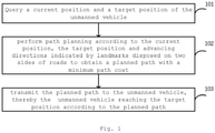
- Fig. 1 is a schematic flow chart of a method for controlling a path of an unmanned vehicle according to one embodiment of the present disclosure. In some embodiments, the following steps of the method for controlling the path of the unmanned vehicle are performed by an apparatus for controlling the path of the unmanned vehicle.
- step 101 a current position and a target position of the unmanned vehicle are queried.
- the current position of the unmanned vehicle is determined based on landmark information on the current position of the unmanned vehicle.
- step 102 path planning is performed according to the current position, the target position and advancing directions indicated by landmarks disposed on two sides of roads to obtain a planned path with a minimum path cost, wherein the unmanned vehicle moves forward on a predetermined side of a road.
- Fig. 2 is a schematic diagram of an application scenario according to an embodiment of the present disclosure.
- the roads on which the unmanned vehicle passes is a bidirectional road, and landmarks indicating the moving direction of the unmanned vehicle are disposed on two sides of the road.
- the unmanned vehicle approaches a predetermined side of the road when moving forward, for example, the unmanned vehicle always approaches the right side of the road when moving forward.
- the roads comprises lanes and main roads, the lane is disposed between the adjacent shelves, and an intersection area between the exit of a lane and a main road is the lane opening.
- a road between adjacent shelves 11 is a lane 12.
- the intersection between the exit of the lane 12 and the main road 13 is a lane opening 14.
- the lane 12 and the main road 13 are provided with landmarks 15 for the two-way moving of an unmanned vehicle.
- step 103 the planned path is transmitted to the unmanned vehicle, thereby the unmanned vehicle reaching the target position according to the planned path.
- the lanes and the main roads in the warehouse are both set as bidirectional roads, so that the unmanned vehicles in different moving directions can conveniently move on different roads, and the road congestion is effectively reduced.
- Fig. 3 is a schematic diagram of an application scenario of another embodiment of the present disclosure. As shown in Fig. 3 , there are three types of landmarks provided on the lanes and the main roads. For simplicity, only part of the landmark types are labeled in Fig. 3 .
- the landmarks contained in the box 21 are first-type landmarks, also called two-way landmarks.
- a two-way landmark i.e. an edge landmark
- the two-way landmark includes an inlet direction and a forward direction. That is, of the two landmarks adjacent to the two-way landmark, the unmanned vehicle moves from the position corresponding to one of the adjacent landmarks to the position corresponding to the two-way landmark along the inlet direction, and moves from the position corresponding to the two-way landmark to the position corresponding to the other adjacent landmark along the forward direction.
- the format information of the two-way landmark is: [X, Y, landmark KEY, Up_NONE_NONE, Down_Inlet_landmark KEY, Left_Outlet_landmark KEY, Right_NONE_NONE], where X, Y represents coordinates of a two-way landmark, the landmark KEY is related information of the landmark, and the up, lower, left or right represents adjacent positions, the Down_Inlet_landmark KEY indicates that an unmanned vehicle can move from a position corresponding to a landmark located below the two-way landmark to a position corresponding to the two-way landmark, and the Left_Outlet _landmark KEY indicates that the unmanned vehicle can move from the position corresponding to the two-way landmark to a position corresponding to the adjacent landmark to the left.
- the unmanned vehicle on the two-way landmark Since the inlet and outlet of a two-way landmark are both unidirectional, and the unmanned vehicle on the two-way landmark has only one advancing direction, the unmanned vehicle thereby passes the position corresponding to the two-way landmark in accordance with the advancing direction.
- the landmarks included in box 22 are landmarks of a second-type, also known as three-way landmarks.
- the three-way landmarks have three adjacent landmarks.
- a three-way landmark includes an inlet direction, a second advancing direction for moving straight forward, and a third advancing direction for turning around.
- the unmanned vehicle can move from the position corresponding to the first adjacent landmark to the position corresponding to the current three-way landmark, and can move forward from the position corresponding to the current three-way landmark to the position corresponding to the second adjacent landmark.
- the unmanned vehicle is also able to traverse between a location corresponding to the current three-way landmark and a location corresponding to a third adjacent landmark (also a three-way landmark).
- the format information of the three-way landmark is: [X, Y, Landmark KEY, Up_Inlet_Landmark KEY, Down_Outlet _Landmark KEY, Left_NONE_NONE, Right_Inlet/Outlet_Landmark KEY].
- the unmanned vehicle can turn around when needed.
- the landmarks included in box 23 are landmarks of a third-type, also known as four-way landmarks.
- the lane opening can be regarded as a crossroad, and four four-way landmarks are disposed in each lane opening.
- the four-way landmark includes two inlet directions, a fourth advancing direction for moving straight forward and a fifth advancing direction for turning around.
- the unmanned vehicle is able to cyclically move between positions corresponding to the four landmarks in each lane opening.
- the four-way landmark has four adjacent landmarks at the up, down, left and right sides, and the unmanned vehicle can move to the position corresponding to the adjacent landmark of the current four-way landmark through the positions corresponding to the two adjacent landmarks and also can move to the positions corresponding to the other two adjacent landmarks from the position corresponding to the current four-way landmark.
- the format information of the four-way landmark is: [X, Y, Landmark KEY, Up_Inlet_Landmark KEY, Down_Outlet _Landmark KEY, left_Outlet_Landmark KEY, Right_Inlet_Landmark KEY] .
- a lane opening in a lane opening, four four-way landmarks can form a counterclockwise cycle, so that the unmanned vehicle can realize various direction adjustments at the lane opening, and the occurrence of congestion can be effectively avoided.
- Fig. 4 is a schematic diagram of an application scenario of another embodiment of the present disclosure.
- the unmanned vehicle in a case where an unmanned vehicle needs to move straight through a lane opening, the unmanned vehicle first arrives at a first position corresponding to a first landmark in the lane opening from a landmark 31. The unmanned vehicle continues to move straight from the first position to a second position corresponding to a second landmark in the lane opening. The unmanned vehicle continues to move straight from the second position to reach the location of the landmark 32 to realize straight through the lane opening.
- the corresponding path is shown as path 41.
- the unmanned vehicle in a case where an unmanned vehicle needs to turn right through a lane opening, the unmanned vehicle first arrives at a first position corresponding to a first landmark in the lane opening from the landmark 33.
- the unmanned vehicle turns to the right from the first position to reach the location of the landmark 34 to realize a right turn through the lane opening.
- the corresponding path is shown as path 42.
- the unmanned vehicle in a case where an unmanned vehicle needs to turn to the left through a lane opening, the unmanned vehicle first arrives at a first position corresponding to a first landmark in the lane opening from a landmark 35.
- the unmanned vehicle continues to move straight from the first position to a second position corresponding to a second landmark in the lane opening.
- the unmanned vehicle turns left from the second position and reaches a third position corresponding to a third landmark in the lane opening.
- the unmanned vehicle continues to move straight from the third position to reach the location of the landmark 36 to realize a left turn through the lane opening.
- the corresponding path is shown as path 43.
- Fig. 5 is a schematic diagram of an application scenario of another embodiment of the present disclosure.
- a first path is planned according to the current position, the target position and an advancing direction indicated by the landmark disposed on the predetermined side of the lane under a condition that the current position and the target position are both located in a same lane, and the unmanned vehicle can reach the target position by moving straight forward without turning around, thereby the unmanned vehicle moving straight forward from the current position to reach the target position according to the first path.
- the unmanned vehicle needs to move from a position corresponding to the landmark 51 to a position corresponding to the landmark 52. Since the unmanned vehicle moves straight ahead to reach the target position, the path 501 can be planned directly between the landmark 51 and the landmark 52.
- a type of the landmark corresponding to the current position is detected under a condition that the current position and the target position are located in the same lane and the unmanned vehicle can reach the target position by turning around. If the type of the landmark corresponding to the current position is a two-way landmark, the unmanned vehicle must turn around. A second path is planned according to the current position, the target position and advancing directions indicated by the landmarks disposed on two sides of the lane, thereby the unmanned vehicle turning around at the current position to reach the target position according to the second path.
- the unmanned vehicle needs to move from a position corresponding to the landmark 53 to a position corresponding to the landmark 55. Since the landmark 53 is a two-way landmark, the unmanned vehicle must turn around to reach the target location, therefore a path 502 can be planned between the landmark 53, the landmark 54, and the landmark 55.
- the current position and the target position are located in the same lane, and the unmanned vehicle reaches the target position by turning around.
- a turning-around position is determined according to the current position and the target position under a condition that the type of the landmark corresponding to the current position is a three-way landmark, wherein the unmanned vehicle can directly reach the target position, or move straight forward to reach the target position, after turning around from the turning-around position to another side of the lane.
- a third path is planned according to the current position, the target position and the advancing directions indicated by landmarks disposed on two sides of the lane under a condition that the turning-around position coincides with the current position, thereby the unmanned vehicle turning around at the current position to reach the target position according to the third path.
- a fourth path is planned according to the current position, the turning-around position, the target position, and the advancing directions indicated by the landmarks disposed on two sides of the lane under a condition that the turning-around position does not coincide with the current position, thereby the unmanned vehicle moving straight forward from the current position to the turning-around position and turning around at the turning-around position to reach the target position according to the fourth path.
- the landmark 56 and the landmark 58 are located on two sides of the road, and the unmanned vehicle needs to turn around to reach the location of the landmark 58. Because the unmanned vehicle can reach the landmark 58 by turning around at the landmark 56 where the unmanned vehicle is currently located, and the landmark 56 is a three-way landmark, the path 503 can be planned between the landmark 56, the landmark 57 and the landmark 58.
- landmark 59 and landmark 511 are located on two sides of the road, and the unmanned vehicle needs to turn around to reach the location of landmark 511.
- the landmark 59 is a three-way landmark
- the unmanned vehicle cannot reach the landmark 511 after turning around at the landmark 59. Therefore, the unmanned vehicle needs to move to landmark 510 firstly.
- the landmark 510 is also a three-way landmark, therefore the unmanned vehicle can turn around from landmark 510 to reach landmark 511.
- Path 504 may thus be planned between landmark 59, landmark 510, and landmark 511.
- Fig. 6 is a schematic diagram of an application scenario of another embodiment of the present disclosure.
- the current position is located in a first lane and the target position is located in a second lane, a first lane opening corresponding to the current position and a second lane opening corresponding to the target position are selected according to the current position and the target position.
- a fifth path is planned according to the current position, the target position, advancing directions indicated by the landmarks disposed in the first lane opening, the advancing directions indicated by the landmarks disposed at two sides of the first lane and the advancing directions indicated by the landmarks disposed at two sides of the second lane under a condition that the first lane opening coincides with the second lane opening, thereby the unmanned vehicle entering the first lane opening from the current position, moving straight forward to pass through the first lane opening and entering the second lane where the targe position is located to reach the target position according to the fifth path.
- the unmanned vehicle needs to move from a position corresponding to the landmark 61 to a position corresponding to the landmark 62. Since the lane opening for leaving the lane where the landmark 61 is located is the same lane opening for entering the lane where the landmark 62 is located, path 601 can be planned using landmark 61, lane opening a1 and landmark 62.
- a sixth path is planned according to the current position, the target position, the advancing directions indicated by the landmarks disposed in the first lane opening, advancing directions indicated by landmarks disposed in the second lane opening, advancing directions indicated by landmarks disposed on two sides of a main road between the first lane opening and the second lane opening, the advancing directions indicated by the landmarks disposed on two sides of the first lane, and advancing directions indicated by landmarks disposed on two sides of the second lane under a condition that the first lane opening does not coincide with the second lane opening, thereby the unmanned vehicle entering the first lane opening from the current position, turning from the first lane opening into the second lane opening, and entering the second lane from the second lane opening to reach the target position according to the sixth path.
- the unmanned vehicle needs to move from a position corresponding to the landmark 63 to a position corresponding to the landmark 64. Since a lane opening a3 for leaving the lane where the landmark 63 is located is not the same as the lane opening a4 for entering the lane were the landmark 64 is located, path 602 can be planned using landmark 63, lane opening a3, lane opening a2 and landmark 64.
- a third lane opening corresponding to the target position is selected according to the current position and the target position under a condition that the current position is within a main road in the roads and the target position is within in a third lane.
- a seventh path is planned according to the current position, the target position, advancing directions indicated by the landmarks disposed at two sides of the main road, advancing directions indicated by the landmarks disposed in the third lane opening and advancing directions indicated by the landmarks disposed at two sides of the third lane, thereby the unmanned vehicle entering the third lane opening from the current position and entering the third lane from the third lane opening to reach the target position according to the seventh path.
- the unmanned vehicle needs to move from landmark 65 to landmark 66.
- Landmark 65 is located on the main road.
- the unmanned vehicle moves to the landmark 66 according to the landmark 65, and selects a lane opening a2 corresponding to the landmark 66.
- Path 603 is thus planned depending on landmark 65, lane opening a2 and landmark 66.
- Fig. 7 is a schematic diagram of an application scenario of still another embodiment of the present disclosure.
- the unmanned vehicle is initially located at the position corresponding to the landmark with coordinates (9, 4), and needs to sequentially reach the positions corresponding to the landmarks with coordinates (5, 1), (4, 2), (2, 0), (1, 1), and (1, 7).
- the unmanned vehicle reaches the landmark with the coordinates (5, 1)
- the landmarks with the coordinates (4, 2), (2, 0), (1, 1) and (1, 7) may also be reached sequentially according to the embodiments of Figs. 1 to 6 .
- Fig. 8 is a schematic structural view of an apparatus for controlling a path of an unmanned vehicle according to one embodiment of the present disclosure. As shown in Fig. 8 , the apparatus includes an querying module 81, a path planning module 82, and a transmitting module 83.
- the querying module 81 is configured to query a current position and a target position of the unmanned vehicle.
- the path planning module 82 is configured to perform path planning according to the current position, the target position and advancing directions indicated by landmarks disposed on two sides of the roads to obtain a planned path with a minimum path cost, wherein the unmanned vehicle moves forward on a predetermined side of a road.
- the path planning module 82 performs path planning according to the embodiments illustrated in Figs. 2-7 .
- the sending module 83 is configured to transmit the planned path to the unmanned vehicle, thereby the unmanned vehicle reaching the target position according to the planned path.
- the lane and the main road in the warehouse are both set as bidirectional roads, so that unmanned vehicles in different moving directions can move on different roads, and the road congestion is effectively reduced.
- Fig. 9 is a schematic structural view of an apparatus for controlling the path of the unmanned vehicle according to another embodiment of the present disclosure. As shown in Fig. 9 , the apparatus includes a memory 91 and a processor 92.
- the memory 91 is used for storing instructions
- the processor 92 is coupled to the memory 91
- the processor 92 is configured to execute the method according to any one of Figs. 1 to 7 based on the instructions stored in the memory.
- the apparatus for controlling the path of the unmanned vehicle further includes a communication interface 93 for information interaction with other devices.
- the apparatus for controlling the path of the unmanned vehicle further comprises a bus 94, and the processor 92, the communication interface 93 and the memory 91 communicate with each other through the bus 94.
- the memory 91 may comprise high-speed RAM memory, and may also include non-volatile memory, such as at least one disk memory.
- the memory 91 may also be a memory array.
- the storage 91 may also be partitioned and the blocks may be combined into virtual volumes according to certain rules.
- processor 92 may be a central processing unit CPU, or may be an application specific integrated circuit ASIC, or one or more integrated circuits configured to implement embodiments of the present disclosure.
- the present disclosure also relates to a computer-readable storage medium, in which computer instructions are stored, and when executed by a processor, the instructions implement the method according to any one of Figs. 1 to 7 .
- Fig. 10 is a schematic structural view of an system for controlling a path of a unmanned vehicle according to an embodiment of the present disclosure.
- the apparatus for controlling the path of the unmanned vehicle includes an unmanned vehicle path control device 1001 and an unmanned vehicle 1002.
- the unmanned vehicle path control device 1001 is the apparatus for controlling the path of the unmanned vehicle according to any one of the embodiments of Figs. 8 and 9 .
- the unmanned vehicle 1002 is configured to provide landmark information on a current location to the unmanned vehicle path control device 1001, so that the unmanned vehicle path control device 1001 plans a path of the unmanned vehicle 1002 from the current location to the target location. After receiving the planned path transmitted by the unmanned vehicle path control device 1001, the unmanned vehicle 1002 travels to the target position according to the planned path.
- the unmanned vehicle 1002 is further configured to identify landmark information set on a road during moving to the target location according to the planned path, and compare the identified landmark information with the planned path. If the recognized landmark information does not coincide with the planned path, the unmanned vehicle 1002 transmits the landmark information on the current position to the unmanned vehicle path control device 1001, so that the unmanned vehicle path control device 1001 replans the path from the current position to the target position of the unmanned vehicle 1002.
- the functional unit modules described above can be implemented as a general purpose Processor, a Programmable Logic Controller (PLC), a Digital Signal Processor (Digital Signal Processor, DSP), an Application Specific Integrated Circuit (ASIC), a Field Programmable Gate Array (FPGA) or other Programmable Logic device, discrete Gate or transistor Logic, discrete hardware components, or any suitable combination thereof for performing the functions described in this disclosure.
- PLC Programmable Logic Controller
- DSP Digital Signal Processor
- ASIC Application Specific Integrated Circuit
- FPGA Field Programmable Gate Array
- other Programmable Logic device discrete Gate or transistor Logic, discrete hardware components, or any suitable combination thereof for performing the functions described in this disclosure.
Landscapes
- Engineering & Computer Science (AREA)
- Remote Sensing (AREA)
- Radar, Positioning & Navigation (AREA)
- Automation & Control Theory (AREA)
- Physics & Mathematics (AREA)
- General Physics & Mathematics (AREA)
- Aviation & Aerospace Engineering (AREA)
- Transportation (AREA)
- Mechanical Engineering (AREA)
- Mathematical Physics (AREA)
- Electromagnetism (AREA)
- Control Of Position, Course, Altitude, Or Attitude Of Moving Bodies (AREA)
- Navigation (AREA)
- Traffic Control Systems (AREA)
Abstract
Description
- The present application is based on and claims priority from
CN application No. 201910411149.1, filed on May 17, 2019 - The disclosure relates to the field of path planning, and in particular relates to a method, a device and a system for controlling a path of an unmanned vehicle.
- In the prior art, automated equipment such as unmanned vehicles have been widely used in warehouse management and production. By providing one-way landmarks on a lane between adjacent shelves and the main road convenient for the unmanned vehicle to pass through, and it can be ensured that the unmanned vehicle moves in a preset path by identifying the one-way landmarks.
- The inventors found through research that congestion is likely to occur because only one-way landmarks are provided on the lanes and the main roads, i.e., unmanned vehicles traveling in different directions use the same landmark. At the lane exit, there are lots of unmanned vehicles moving straight forward, turning left or turning right, which intensifies the condition of traffic jam and seriously affects working efficiency.
- To this end, the present disclosure provides an unmanned vehicle path control scheme that reduces congestion conditions.
- According to a first aspect of an embodiment of the present disclosure, there is provided a method for controlling a path of an unmanned vehicle, comprising: querying a current position and a target position of the unmanned vehicle; performing path planning according to the current position, the target position and advancing directions indicated by landmarks disposed on two sides of roads to obtain a planned path with a minimum path cost, wherein the unmanned vehicle moves forward on a predetermined side of a road; and transmitting the planned path to the unmanned vehicle, thereby the unmanned vehicle reaching the target position according to the planned path.
- In some embodiments, the performing path planning according to the current position, the target position and advancing directions indicated by landmarks disposed on two sides of the roads comprises: determining whether the current position and the target position are both located in a first lane in the roads; determining whether the unmanned vehicle can reach the target position by moving straight forward without turning around according to an advancing direction indicated by a landmark corresponding to the current position under a condition that the current position and the target position are both located in a first lane; and planning a first path according to the current position, the target position and an advancing direction indicated by the landmark disposed on the predetermined side of the first lane under a condition that the unmanned vehicle can reach the target position by moving straight forward without turning around, thereby the unmanned vehicle moving straight forward from the current position to reach the target position according to the first path.
- In some embodiments, detecting a type of the landmark corresponding to the current position under a condition that the unmanned vehicle reaches the target position by turning around; and planning a second path according to the current position, the target position and advancing directions indicated by the landmarks disposed on two sides of the first lane under a condition that the type of the landmark corresponding to the current position is a first-type of the landmark, thereby the unmanned vehicle turning around at the current position to reach the target position according to the second path, wherein the first-type of the landmark comprises a first advancing direction for turning around.
- In some embodiments, determining a turning-around position according to the current position, the target position and the advancing direction of the landmark corresponding to the current position under a condition that the type of the landmark corresponding to the current position is a second-type of the landmark, thereby the unmanned vehicle directly reaching the target position, or moving straight forward to reach the target position, after turning around from the turning-around position to another side of the lane, wherein the second-type of the landmark comprises a second advancing direction for moving straight forward and a third advancing direction for turning around; determining whether the turning-around position coincides with the current position; and planning a third path according to the current position, the target position and the advancing directions indicated by landmarks disposed on two sides of the first lane under a condition that the turning-around position coincides with the current position, thereby the unmanned vehicle turning around at the current position to reach the target position according to the third path.
- In some embodiments, planning a fourth path according to the current position, the turning-around position, the target position, and the advancing directions indicated by the landmarks disposed on two sides of the first lane under a condition that the turning-around position does not coincide with the current position, thereby the unmanned vehicle moving straight forward from the current position to the turning-around position and turning around at the turning-around position to reach the target position according to the fourth path.
- In some embodiments, selecting a first lane opening corresponding to the current location and a second lane opening corresponding to the target location according to the current location and the target location under a condition that the current location is within the first lane and the target location is within a second lane in the roads, wherein a lane opening is an intersection area between an exit of a corresponding lane and a main road in the roads; and planning a fifth path according to the current position, the target position, advancing directions indicated by the landmarks disposed in the first lane opening, the advancing directions indicated by the landmarks disposed at two sides of the first lane and the advancing directions indicated by the landmarks disposed at two sides of the second lane under a condition that the first lane opening coincides with the second lane opening, thereby the unmanned vehicle entering the first lane opening from the current position, moving straight forward to pass through the first lane opening and entering the second lane to reach the target position according to the fifth path.
- In some embodiments, planning a sixth path according to the current position, the target position, the advancing directions indicated by the landmarks disposed in the first lane opening, advancing directions indicated by landmarks disposed in the second lane opening, advancing directions indicated by landmarks disposed on two sides of a first main road between the first lane opening and the second lane opening, the advancing directions indicated by the landmarks disposed on two sides of the first lane, and advancing directions indicated by landmarks disposed on two sides of the second lane under a condition that the first lane opening does not coincide with the second lane opening, thereby the unmanned vehicle entering the first lane opening from the current position, turning from the first lane opening into the first main road, entering the second lane opening from the first main road, and entering the second lane from the second lane opening to reach the target position according to the sixth path.
- In some embodiments, selecting a third lane opening corresponding to the target position according to the current position and the target position under a condition that the current position is within a second main road in the roads and the target position is within in a third lane in the roads; and planning a seventh path according to the current position, the target position, advancing directions indicated by the landmarks disposed at two sides of the second main road, advancing directions indicated by the landmarks disposed in the third lane opening and advancing directions indicated by the landmarks disposed at two sides of the third lane, thereby the unmanned vehicle entering the third lane opening from the current position and entering the third lane from the third lane opening to reach the target position according to the seventh path.
- In some embodiments, each lane opening includes four third-type landmarks, each third-type landmark comprises a fourth advancing direction for moving straight forward and a fifth advancing direction for turning around, the unmanned vehicle can cyclically move between positions corresponding to the four third-type landmarks in each lane opening.
- In some embodiments, controlling the unmanned vehicle to reach a first position corresponding to a first landmark in a predetermined lane opening under a condition that the unmanned vehicle moving straight forward through a predetermined lane opening; controlling the unmanned vehicle to move straight forward from the first position to reach a second position corresponding to a second landmark in the predetermined lane opening; and controlling the unmanned vehicle to move straight forward from the second position to pass through the predetermined lane opening.
- In some embodiments, controlling the unmanned vehicle to reach a first position corresponding to the first landmark in the predetermined lane opening under a condition that the unmanned vehicle turning to a predetermined side through a predetermined lane opening; and controlling the unmanned vehicle to turn from the first position to the predetermined side, thereby the unmanned vehicle turning to the predetermined side through the predetermined lane opening.
- In some embodiments, controlling the unmanned vehicle to reach a first position corresponding to the first landmark in the predetermined lane opening under a condition that the unmanned vehicle turning to an opposite side of the predetermined side through a predetermined lane opening; controlling the unmanned vehicle to move straight forward from the first position to reach a second position corresponding to the second landmark in the predetermined lane opening; controlling the unmanned vehicle to turn from the second position to the opposite side of the predetermined side to reach a third position corresponding to a third landmark in a predetermined lane opening; and controlling the unmanned vehicle to move straight forward from the third position, thereby the unmanned vehicle turning to an opposite side of the predetermined side through the predetermined lane opening.
- In some embodiments, the querying the current position of the unmanned vehicle comprises: determining the current position of the unmanned vehicle according to a landmark information on the current position of the unmanned vehicle.
- According to a second aspect of the embodiments of the present disclosure, there is provided an apparatus for controlling a path of an unmanned vehicle, comprising: a querying module, configured to query a current position and a target position of the unmanned vehicle; a path planning module, configured to perform path planning according to the current position, the target position and advancing directions indicated by landmarks disposed on two sides of roads to obtain a planned path with a minimum path cost, wherein the unmanned vehicle moves forward on a predetermined side of the road; a transmitting module, configured to transmit the planned path to the unmanned vehicle, thereby the unmanned vehicle reaching the target position according to the planned path.
- According to a third aspect of the embodiments of the present disclosure, there is provided an apparatus for controlling a path of an unmanned vehicle, comprising: a memory configured to store instructions; a processor coupled to the memory, wherein based on the instructions stored in the memory, the processor is configured to implement the method according to any one of the embodiments described above.
- According to a fourth aspect of the embodiments of the present disclosure, there is provided an system for controlling a path of an unmanned vehicle, comprising: an apparatus for controlling a path of an unmanned vehicle according to any one of the embodiments described above, and an unmanned vehicle, configured to transmit landmark information on a current position to the apparatus, thereby the apparatus planning a path from the current position to a target position of the unmanned vehicle, and configured to move to the target position according to a planned path transmitted by the apparatus.
- In some embodiments, the unmanned vehicle is further configured to identify landmark information of landmarks disposed on two sides of roads during moving to the target position according to the planned path, compare identified landmark information with the planned path, and transmit the landmark information at the current position to the apparatus under a condition that the identified landmark information does not consistent with the planned path, thereby the apparatus replanning a path from the current position to the target position.
- According to a fifth aspect of the embodiments of the present disclosure, there is provided a computer-readable storage medium, wherein the computer readable storage medium stores computer instructions which, when executed by a processor, cause the processor to implement the method according to any one of the embodiments described above.
- Other features of the present disclosure and advantages thereof will become apparent from the following detailed description of exemplary embodiments thereof, which proceeds with reference to the accompanying drawings.
- In order to more clearly illustrate the embodiments of the present disclosure or the technical solutions in the prior art, the drawings used in the embodiments or the description of the prior art will be briefly described below. Apparently, the drawings in the following description are only some of the embodiments of the present disclosure, and for those skilled in the art, other drawings may be obtained according to the drawings without paying inventive effort.
-
Fig. 1 is a schematic flow chart of a method for controlling a path of an unmanned vehicle according to one embodiment of the present disclosure; -
FIG. 2 is a schematic diagram of an application scenario of one embodiment of the present disclosure; -
FIG. 3 is a schematic diagram of an application scenario of another embodiment of the present disclosure; -
FIG. 4 is a schematic illustration of an application scenario of still another embodiment of the present disclosure; -
FIG. 5 is a schematic illustration of an application scenario of still another embodiment of the present disclosure; -
FIG. 6 is a schematic illustration of an application scenario of still another embodiment of the present disclosure; -
FIG. 7 is a schematic illustration of an application scenario of still another embodiment of the present disclosure; -
Fig. 8 is a schematic structural view of an apparatus for controlling a path of an unmanned vehicle according to one embodiment of the present disclosure; -
Fig. 9 is a schematic structural view of an apparatus for controlling a path of an unmanned vehicle according to another embodiment of the present disclosure; -
Fig. 10 is a schematic structural view of an system for controlling a path of an unmanned vehicle according to another embodiment of the present disclosure. - The technical solutions in the embodiments of the present disclosure will be described clearly and completely with reference to the drawings in the embodiments of the present disclosure, and it is obvious that the embodiments described are only some, instead of all, of the embodiments of the present disclosure. The following description of at least one exemplary embodiment is merely illustrative in nature and is in no way intended to limit the disclosure, its application, or uses. All other embodiments, which can be derived by a person skilled in the art from the embodiments disclosed herein without inventive step, are intended to be within the scope of the present disclosure.
- The relative arrangement of parts and steps, numerical expressions and values set forth in these embodiments do not limit the scope of the present disclosure unless specifically stated otherwise.
- Meanwhile, it should be understood that the sizes of the respective portions shown in the drawings are not drawn in an actual proportional relationship for the convenience of description.
- Techniques, methods, and apparatus known to one of ordinary skill in the relevant art may not be discussed in detail but are intended to be part of the specification where appropriate.
- In all examples shown and discussed herein, any particular value should be construed as exemplary only and not as limiting. Thus, other examples of the exemplary embodiments may have different values.
- It should be noted that similar reference signs and letters refer to similar items in the following figures, and thus, once an item is defined in one figure, it need not be discussed further in subsequent figures.
-
Fig. 1 is a schematic flow chart of a method for controlling a path of an unmanned vehicle according to one embodiment of the present disclosure. In some embodiments, the following steps of the method for controlling the path of the unmanned vehicle are performed by an apparatus for controlling the path of the unmanned vehicle. - In
step 101, a current position and a target position of the unmanned vehicle are queried. - In some embodiments, the current position of the unmanned vehicle is determined based on landmark information on the current position of the unmanned vehicle.
- In
step 102, path planning is performed according to the current position, the target position and advancing directions indicated by landmarks disposed on two sides of roads to obtain a planned path with a minimum path cost, wherein the unmanned vehicle moves forward on a predetermined side of a road. -
Fig. 2 is a schematic diagram of an application scenario according to an embodiment of the present disclosure. Here, the roads on which the unmanned vehicle passes is a bidirectional road, and landmarks indicating the moving direction of the unmanned vehicle are disposed on two sides of the road. The unmanned vehicle approaches a predetermined side of the road when moving forward, for example, the unmanned vehicle always approaches the right side of the road when moving forward. The roads comprises lanes and main roads, the lane is disposed between the adjacent shelves, and an intersection area between the exit of a lane and a main road is the lane opening. - As shown in
Fig. 2 , a road betweenadjacent shelves 11 is alane 12. The intersection between the exit of thelane 12 and themain road 13 is a lane opening 14. Thelane 12 and themain road 13 are provided withlandmarks 15 for the two-way moving of an unmanned vehicle. - In
step 103, the planned path is transmitted to the unmanned vehicle, thereby the unmanned vehicle reaching the target position according to the planned path. - In the method for controlling the path of the unmanned vehicle provided by the above embodiment of the disclosure, the lanes and the main roads in the warehouse are both set as bidirectional roads, so that the unmanned vehicles in different moving directions can conveniently move on different roads, and the road congestion is effectively reduced.
-
Fig. 3 is a schematic diagram of an application scenario of another embodiment of the present disclosure. As shown inFig. 3 , there are three types of landmarks provided on the lanes and the main roads. For simplicity, only part of the landmark types are labeled inFig. 3 . - The landmarks contained in the
box 21 are first-type landmarks, also called two-way landmarks. - A two-way landmark, i.e. an edge landmark, has only two landmarks adjacent to it. The two-way landmark includes an inlet direction and a forward direction. That is, of the two landmarks adjacent to the two-way landmark, the unmanned vehicle moves from the position corresponding to one of the adjacent landmarks to the position corresponding to the two-way landmark along the inlet direction, and moves from the position corresponding to the two-way landmark to the position corresponding to the other adjacent landmark along the forward direction.
- For example, the format information of the two-way landmark is: [X, Y, landmark KEY, Up_NONE_NONE, Down_Inlet_landmark KEY, Left_Outlet_landmark KEY, Right_NONE_NONE], where X, Y represents coordinates of a two-way landmark, the landmark KEY is related information of the landmark, and the up, lower, left or right represents adjacent positions, the Down_Inlet_landmark KEY indicates that an unmanned vehicle can move from a position corresponding to a landmark located below the two-way landmark to a position corresponding to the two-way landmark, and the Left_Outlet _landmark KEY indicates that the unmanned vehicle can move from the position corresponding to the two-way landmark to a position corresponding to the adjacent landmark to the left.
- Since the inlet and outlet of a two-way landmark are both unidirectional, and the unmanned vehicle on the two-way landmark has only one advancing direction, the unmanned vehicle thereby passes the position corresponding to the two-way landmark in accordance with the advancing direction.
- The landmarks included in
box 22 are landmarks of a second-type, also known as three-way landmarks. - The three-way landmarks have three adjacent landmarks. A three-way landmark includes an inlet direction, a second advancing direction for moving straight forward, and a third advancing direction for turning around. The unmanned vehicle can move from the position corresponding to the first adjacent landmark to the position corresponding to the current three-way landmark, and can move forward from the position corresponding to the current three-way landmark to the position corresponding to the second adjacent landmark. In addition, the unmanned vehicle is also able to traverse between a location corresponding to the current three-way landmark and a location corresponding to a third adjacent landmark (also a three-way landmark).
- For example, the format information of the three-way landmark is: [X, Y, Landmark KEY, Up_Inlet_Landmark KEY, Down_Outlet _Landmark KEY, Left_NONE_NONE, Right_Inlet/Outlet_Landmark KEY].
- Since the inlet and the outlet of the three-way landmark are both bidirectional, the unmanned vehicle can turn around when needed.
- The landmarks included in
box 23 are landmarks of a third-type, also known as four-way landmarks. - The lane opening can be regarded as a crossroad, and four four-way landmarks are disposed in each lane opening. The four-way landmark includes two inlet directions, a fourth advancing direction for moving straight forward and a fifth advancing direction for turning around. The unmanned vehicle is able to cyclically move between positions corresponding to the four landmarks in each lane opening. The four-way landmark has four adjacent landmarks at the up, down, left and right sides, and the unmanned vehicle can move to the position corresponding to the adjacent landmark of the current four-way landmark through the positions corresponding to the two adjacent landmarks and also can move to the positions corresponding to the other two adjacent landmarks from the position corresponding to the current four-way landmark.
- For example, the format information of the four-way landmark is: [X, Y, Landmark KEY, Up_Inlet_Landmark KEY, Down_Outlet _Landmark KEY, left_Outlet_Landmark KEY, Right_Inlet_Landmark KEY] .
- As shown in
Fig. 3 , in a lane opening, four four-way landmarks can form a counterclockwise cycle, so that the unmanned vehicle can realize various direction adjustments at the lane opening, and the occurrence of congestion can be effectively avoided. -
Fig. 4 is a schematic diagram of an application scenario of another embodiment of the present disclosure. - As shown on the right side of
Fig. 4 , in a case where an unmanned vehicle needs to move straight through a lane opening, the unmanned vehicle first arrives at a first position corresponding to a first landmark in the lane opening from a landmark 31. The unmanned vehicle continues to move straight from the first position to a second position corresponding to a second landmark in the lane opening. The unmanned vehicle continues to move straight from the second position to reach the location of thelandmark 32 to realize straight through the lane opening. The corresponding path is shown aspath 41. - As shown in the middle of
Fig. 4 , in a case where an unmanned vehicle needs to turn right through a lane opening, the unmanned vehicle first arrives at a first position corresponding to a first landmark in the lane opening from the landmark 33. The unmanned vehicle turns to the right from the first position to reach the location of thelandmark 34 to realize a right turn through the lane opening. The corresponding path is shown as path 42. - As shown on the left side of
Fig. 4 , in a case where an unmanned vehicle needs to turn to the left through a lane opening, the unmanned vehicle first arrives at a first position corresponding to a first landmark in the lane opening from alandmark 35. The unmanned vehicle continues to move straight from the first position to a second position corresponding to a second landmark in the lane opening. The unmanned vehicle turns left from the second position and reaches a third position corresponding to a third landmark in the lane opening. The unmanned vehicle continues to move straight from the third position to reach the location of thelandmark 36 to realize a left turn through the lane opening. The corresponding path is shown aspath 43. -
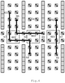
Fig. 5 is a schematic diagram of an application scenario of another embodiment of the present disclosure. - As shown in
Fig. 5 , in some embodiments, a first path is planned according to the current position, the target position and an advancing direction indicated by the landmark disposed on the predetermined side of the lane under a condition that the current position and the target position are both located in a same lane, and the unmanned vehicle can reach the target position by moving straight forward without turning around, thereby the unmanned vehicle moving straight forward from the current position to reach the target position according to the first path. - As shown in the upper right portion of
Fig. 5 , the unmanned vehicle needs to move from a position corresponding to thelandmark 51 to a position corresponding to thelandmark 52. Since the unmanned vehicle moves straight ahead to reach the target position, thepath 501 can be planned directly between thelandmark 51 and thelandmark 52. - In some embodiments, a type of the landmark corresponding to the current position is detected under a condition that the current position and the target position are located in the same lane and the unmanned vehicle can reach the target position by turning around. If the type of the landmark corresponding to the current position is a two-way landmark, the unmanned vehicle must turn around. A second path is planned according to the current position, the target position and advancing directions indicated by the landmarks disposed on two sides of the lane, thereby the unmanned vehicle turning around at the current position to reach the target position according to the second path.
- As shown in the upper left portion of
Fig. 5 , the unmanned vehicle needs to move from a position corresponding to thelandmark 53 to a position corresponding to thelandmark 55. Since thelandmark 53 is a two-way landmark, the unmanned vehicle must turn around to reach the target location, therefore apath 502 can be planned between thelandmark 53, thelandmark 54, and thelandmark 55. - In some embodiments, the current position and the target position are located in the same lane, and the unmanned vehicle reaches the target position by turning around. A turning-around position is determined according to the current position and the target position under a condition that the type of the landmark corresponding to the current position is a three-way landmark, wherein the unmanned vehicle can directly reach the target position, or move straight forward to reach the target position, after turning around from the turning-around position to another side of the lane. A third path is planned according to the current position, the target position and the advancing directions indicated by landmarks disposed on two sides of the lane under a condition that the turning-around position coincides with the current position, thereby the unmanned vehicle turning around at the current position to reach the target position according to the third path. A fourth path is planned according to the current position, the turning-around position, the target position, and the advancing directions indicated by the landmarks disposed on two sides of the lane under a condition that the turning-around position does not coincide with the current position, thereby the unmanned vehicle moving straight forward from the current position to the turning-around position and turning around at the turning-around position to reach the target position according to the fourth path.
- As shown in the lower right portion of
Fig. 5 , thelandmark 56 and the landmark 58 are located on two sides of the road, and the unmanned vehicle needs to turn around to reach the location of the landmark 58. Because the unmanned vehicle can reach the landmark 58 by turning around at thelandmark 56 where the unmanned vehicle is currently located, and thelandmark 56 is a three-way landmark, thepath 503 can be planned between thelandmark 56, thelandmark 57 and the landmark 58. - In the lower left portion of
Fig. 5 ,landmark 59 andlandmark 511 are located on two sides of the road, and the unmanned vehicle needs to turn around to reach the location oflandmark 511. Although thelandmark 59 is a three-way landmark, the unmanned vehicle cannot reach thelandmark 511 after turning around at thelandmark 59. Therefore, the unmanned vehicle needs to move tolandmark 510 firstly. Thelandmark 510 is also a three-way landmark, therefore the unmanned vehicle can turn around fromlandmark 510 to reachlandmark 511.Path 504 may thus be planned betweenlandmark 59,landmark 510, andlandmark 511. -
Fig. 6 is a schematic diagram of an application scenario of another embodiment of the present disclosure. - In some embodiments, as shown in
Fig. 6 , the current position is located in a first lane and the target position is located in a second lane, a first lane opening corresponding to the current position and a second lane opening corresponding to the target position are selected according to the current position and the target position. A fifth path is planned according to the current position, the target position, advancing directions indicated by the landmarks disposed in the first lane opening, the advancing directions indicated by the landmarks disposed at two sides of the first lane and the advancing directions indicated by the landmarks disposed at two sides of the second lane under a condition that the first lane opening coincides with the second lane opening, thereby the unmanned vehicle entering the first lane opening from the current position, moving straight forward to pass through the first lane opening and entering the second lane where the targe position is located to reach the target position according to the fifth path. - As shown in the right part of
Fig. 6 , the unmanned vehicle needs to move from a position corresponding to thelandmark 61 to a position corresponding to thelandmark 62. Since the lane opening for leaving the lane where thelandmark 61 is located is the same lane opening for entering the lane where thelandmark 62 is located,path 601 can be planned usinglandmark 61, lane opening a1 andlandmark 62. - In some embodiments, upon selection of a first lane opening corresponding to the current location and a second lane opening corresponding to the target location, a sixth path is planned according to the current position, the target position, the advancing directions indicated by the landmarks disposed in the first lane opening, advancing directions indicated by landmarks disposed in the second lane opening, advancing directions indicated by landmarks disposed on two sides of a main road between the first lane opening and the second lane opening, the advancing directions indicated by the landmarks disposed on two sides of the first lane, and advancing directions indicated by landmarks disposed on two sides of the second lane under a condition that the first lane opening does not coincide with the second lane opening, thereby the unmanned vehicle entering the first lane opening from the current position, turning from the first lane opening into the second lane opening, and entering the second lane from the second lane opening to reach the target position according to the sixth path.
- As shown in the left part of
Fig. 6 , the unmanned vehicle needs to move from a position corresponding to thelandmark 63 to a position corresponding to thelandmark 64. Since a lane opening a3 for leaving the lane where thelandmark 63 is located is not the same as the lane opening a4 for entering the lane were thelandmark 64 is located,path 602 can be planned usinglandmark 63, lane opening a3, lane opening a2 andlandmark 64. - In some embodiments, a third lane opening corresponding to the target position is selected according to the current position and the target position under a condition that the current position is within a main road in the roads and the target position is within in a third lane. A seventh path is planned according to the current position, the target position, advancing directions indicated by the landmarks disposed at two sides of the main road, advancing directions indicated by the landmarks disposed in the third lane opening and advancing directions indicated by the landmarks disposed at two sides of the third lane, thereby the unmanned vehicle entering the third lane opening from the current position and entering the third lane from the third lane opening to reach the target position according to the seventh path.
- As shown in the left portion of
Fig. 6 , the unmanned vehicle needs to move fromlandmark 65 tolandmark 66.Landmark 65 is located on the main road. The unmanned vehicle moves to thelandmark 66 according to thelandmark 65, and selects a lane opening a2 corresponding to thelandmark 66.Path 603 is thus planned depending onlandmark 65, lane opening a2 andlandmark 66. -
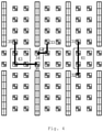
Fig. 7 is a schematic diagram of an application scenario of still another embodiment of the present disclosure. As shown inFig. 7 , the unmanned vehicle is initially located at the position corresponding to the landmark with coordinates (9, 4), and needs to sequentially reach the positions corresponding to the landmarks with coordinates (5, 1), (4, 2), (2, 0), (1, 1), and (1, 7). - According to the embodiments of
Figs. 1 to 6 , in the process that the unmanned vehicle arrives at the landmark with the coordinates (5, 1) from the landmark with the coordinates (9, 4), the corresponding information of the landmarks it passes is as follows: - [9, 4, KEY/9/4, Up_NONE_NONE, Down_Inlet_KEY/9/5, Left_Outlet _KEY/8/5, Right_NONE_NONE];
- [8, 4, KEY/8/4, Up_Outlet_KEY/8/3, Down_Inlet_KEY/8/5, Left _Outlet_KEY/7/4, Right_Inlet_KEY/9/4];
- [5, 2, KEY/5/2, Up_Outlet_KEY/5/1, Down_Inlet_KEY/5/3, Left _Inlet/Outlet_KEY/4/2, Right_NONE_NONE];
- [5, 1, KEY/5/1, Up_Outlet_KEY/5/0, Down_Inlet_KEY/5/2, Left _Inlet/Outlet_KEY/4/1, Right_NONE_NONE].
- Accordingly, after the unmanned vehicle reaches the landmark with the coordinates (5, 1), the landmarks with the coordinates (4, 2), (2, 0), (1, 1) and (1, 7) may also be reached sequentially according to the embodiments of
Figs. 1 to 6 . -
Fig. 8 is a schematic structural view of an apparatus for controlling a path of an unmanned vehicle according to one embodiment of the present disclosure. As shown inFig. 8 , the apparatus includes anquerying module 81, apath planning module 82, and a transmittingmodule 83. - The
querying module 81 is configured to query a current position and a target position of the unmanned vehicle. - The
path planning module 82 is configured to perform path planning according to the current position, the target position and advancing directions indicated by landmarks disposed on two sides of the roads to obtain a planned path with a minimum path cost, wherein the unmanned vehicle moves forward on a predetermined side of a road. - In some embodiments, the
path planning module 82 performs path planning according to the embodiments illustrated inFigs. 2-7 . - The sending
module 83 is configured to transmit the planned path to the unmanned vehicle, thereby the unmanned vehicle reaching the target position according to the planned path. - In the apparatus for controlling the path of the unmanned vehicle provided by the above embodiment of the present disclosure, the lane and the main road in the warehouse are both set as bidirectional roads, so that unmanned vehicles in different moving directions can move on different roads, and the road congestion is effectively reduced.
-
Fig. 9 is a schematic structural view of an apparatus for controlling the path of the unmanned vehicle according to another embodiment of the present disclosure. As shown inFig. 9 , the apparatus includes amemory 91 and aprocessor 92. - The
memory 91 is used for storing instructions, theprocessor 92 is coupled to thememory 91, and theprocessor 92 is configured to execute the method according to any one ofFigs. 1 to 7 based on the instructions stored in the memory. - As shown in
Fig. 9 , the apparatus for controlling the path of the unmanned vehicle further includes acommunication interface 93 for information interaction with other devices. Meanwhile, the apparatus for controlling the path of the unmanned vehicle further comprises abus 94, and theprocessor 92, thecommunication interface 93 and thememory 91 communicate with each other through thebus 94. - The
memory 91 may comprise high-speed RAM memory, and may also include non-volatile memory, such as at least one disk memory. Thememory 91 may also be a memory array. Thestorage 91 may also be partitioned and the blocks may be combined into virtual volumes according to certain rules. - Further, the
processor 92 may be a central processing unit CPU, or may be an application specific integrated circuit ASIC, or one or more integrated circuits configured to implement embodiments of the present disclosure. - The present disclosure also relates to a computer-readable storage medium, in which computer instructions are stored, and when executed by a processor, the instructions implement the method according to any one of
Figs. 1 to 7 . -
Fig. 10 is a schematic structural view of an system for controlling a path of a unmanned vehicle according to an embodiment of the present disclosure. As shown inFig. 10 , the apparatus for controlling the path of the unmanned vehicle includes an unmanned vehiclepath control device 1001 and anunmanned vehicle 1002. The unmanned vehiclepath control device 1001 is the apparatus for controlling the path of the unmanned vehicle according to any one of the embodiments ofFigs. 8 and9 . - The
unmanned vehicle 1002 is configured to provide landmark information on a current location to the unmanned vehiclepath control device 1001, so that the unmanned vehiclepath control device 1001 plans a path of theunmanned vehicle 1002 from the current location to the target location. After receiving the planned path transmitted by the unmanned vehiclepath control device 1001, theunmanned vehicle 1002 travels to the target position according to the planned path. - In some embodiments, the
unmanned vehicle 1002 is further configured to identify landmark information set on a road during moving to the target location according to the planned path, and compare the identified landmark information with the planned path. If the recognized landmark information does not coincide with the planned path, theunmanned vehicle 1002 transmits the landmark information on the current position to the unmanned vehiclepath control device 1001, so that the unmanned vehiclepath control device 1001 replans the path from the current position to the target position of theunmanned vehicle 1002. - In some embodiments, the functional unit modules described above can be implemented as a general purpose Processor, a Programmable Logic Controller (PLC), a Digital Signal Processor (Digital Signal Processor, DSP), an Application Specific Integrated Circuit (ASIC), a Field Programmable Gate Array (FPGA) or other Programmable Logic device, discrete Gate or transistor Logic, discrete hardware components, or any suitable combination thereof for performing the functions described in this disclosure.
- It will be understood by those skilled in the art that all or part of the steps for implementing the above embodiments may be implemented by hardware, or may be implemented by a program instructing relevant hardware, where the program may be stored in a computer-readable storage medium, and the storage medium may be a read-only memory, a magnetic disk or an optical disk.
- The description of the present disclosure has been presented for purposes of illustration and description, and is not intended to be exhaustive or limited to the disclosure in the form disclosed. Many modifications and variations will be apparent to practitioners skilled in this art. The embodiment was chosen and described in order to best explain the principles of the disclosure and the practical application, and to enable others of ordinary skill in the art to understand the disclosure for various embodiments with various modifications as are suited to the particular use contemplated.
Claims (18)
- A method for controlling a path of an unmanned vehicle, comprising:querying a current position and a target position of the unmanned vehicle;performing path planning according to the current position, the target position and advancing directions indicated by landmarks disposed on two sides of roads to obtain a planned path with a minimum path cost, wherein the unmanned vehicle moves forward on a predetermined side of a road; andtransmitting the planned path to the unmanned vehicle, thereby the unmanned vehicle reaching the target position according to the planned path.
- The method according to claim 1, wherein the performing path planning according to the current position, the target position and advancing directions indicated by landmarks disposed on two sides of the roads comprises:determining whether the current position and the target position are both located in a first lane in the roads;determining whether the unmanned vehicle can reach the target position by moving straight forward without turning around according to an advancing direction indicated by a landmark corresponding to the current position under a condition that the current position and the target position are both located in a first lane; andplanning a first path according to the current position, the target position and an advancing direction indicated by the landmark disposed on the predetermined side of the first lane under a condition that the unmanned vehicle can reach the target position by moving straight forward without turning around, thereby the unmanned vehicle moving straight forward from the current position to reach the target position according to the first path.
- The method according to claim 2, wherein the performing path planning according to the current position, the target position and advancing directions indicated by landmarks disposed on two sides of the roads comprises:detecting a type of the landmark corresponding to the current position under a condition that the unmanned vehicle reaches the target position by turning around; andplanning a second path according to the current position, the target position and advancing directions indicated by the landmarks disposed on two sides of the first lane under a condition that the type of the landmark corresponding to the current position is a first-type of the landmark, thereby the unmanned vehicle turning around at the current position to reach the target position according to the second path, wherein the first-type of the landmark comprises a first advancing direction for turning around.
- The method according to claim 3, wherein the performing path planning according to the current position, the target position and advancing directions indicated by landmarks disposed on two sides of the roads comprises:determining a turning-around position according to the current position, the target position and the advancing direction of the landmark corresponding to the current position under a condition that the type of the landmark corresponding to the current position is a second-type of the landmark, thereby the unmanned vehicle directly reaching the target position, or moving straight forward to reach the target position, after turning around from the turning-around position to another side of the lane, wherein the second-type of the landmark comprises a second advancing direction for moving straight forward and a third advancing direction for turning around;determining whether the turning-around position coincides with the current position; andplanning a third path according to the current position, the target position and the advancing directions indicated by landmarks disposed on two sides of the first lane under a condition that the turning-around position coincides with the current position, thereby the unmanned vehicle turning around at the current position to reach the target position according to the third path.
- The method according to Claim 4, wherein the performing path planning according to the current position, the target position and advancing directions indicated by landmarks disposed on two sides of the roads comprises:
planning a fourth path according to the current position, the turning-around position, the target position, and the advancing directions indicated by the landmarks disposed on two sides of the first lane under a condition that the turning-around position does not coincide with the current position, thereby the unmanned vehicle moving straight forward from the current position to the turning-around position and turning around at the turning-around position to reach the target position according to the fourth path. - The method according to claim 2, wherein the performing path planning according to the current position, the target position and advancing directions indicated by landmarks disposed on two sides of the roads comprises:selecting a first lane opening corresponding to the current location and a second lane opening corresponding to the target location according to the current location and the target location under a condition that the current location is within the first lane and the target location is within a second lane in the roads, wherein a lane opening is an intersection area between an exit of a corresponding lane and a main road in the roads; andplanning a fifth path according to the current position, the target position, advancing directions indicated by the landmarks disposed in the first lane opening, the advancing directions indicated by the landmarks disposed at two sides of the first lane and the advancing directions indicated by the landmarks disposed at two sides of the second lane under a condition that the first lane opening coincides with the second lane opening, thereby the unmanned vehicle entering the first lane opening from the current position, moving straight forward to pass through the first lane opening and entering the second lane to reach the target position according to the fifth path.
- The method according to claim 6, wherein the performing path planning according to the current position, the target position and advancing directions indicated by landmarks disposed on two sides of the roads comprises:
planning a sixth path according to the current position, the target position, the advancing directions indicated by the landmarks disposed in the first lane opening, advancing directions indicated by landmarks disposed in the second lane opening, advancing directions indicated by landmarks disposed on two sides of a first main road between the first lane opening and the second lane opening, the advancing directions indicated by the landmarks disposed on two sides of the first lane, and advancing directions indicated by landmarks disposed on two sides of the second lane under a condition that the first lane opening does not coincide with the second lane opening, thereby the unmanned vehicle entering the first lane opening from the current position, turning from the first lane opening into the first main road, entering the second lane opening from the first main road, and entering the second lane from the second lane opening to reach the target position according to the sixth path. - The method according to claim 2, wherein the performing path planning according to the current position, the target position and advancing directions indicated by landmarks disposed on two sides of the roads comprises:selecting a third lane opening corresponding to the target position according to the current position and the target position under a condition that the current position is within a second main road in the roads and the target position is within in a third lane in the roads; andplanning a seventh path according to the current position, the target position, advancing directions indicated by the landmarks disposed at two sides of the second main road, advancing directions indicated by the landmarks disposed in the third lane opening and advancing directions indicated by the landmarks disposed at two sides of the third lane, thereby the unmanned vehicle entering the third lane opening from the current position and entering the third lane from the third lane opening to reach the target position according to the seventh path.
- The method according to claim 8, wherein
each lane opening includes four third-type landmarks, each third-type landmark comprises a fourth advancing direction for moving straight forward and a fifth advancing direction for turning around, the unmanned vehicle can cyclically move between positions corresponding to the four third-type landmarks in each lane opening. - The method according to claim 9, wherein:controlling the unmanned vehicle to reach a first position corresponding to a first landmark in a predetermined lane opening under a condition that the unmanned vehicle moving straight forward through a predetermined lane opening;controlling the unmanned vehicle to move straight forward from the first position to reach a second position corresponding to a second landmark in the predetermined lane opening; andcontrolling the unmanned vehicle to move straight forward from the second position to pass through the predetermined lane opening.
- The method according to claim 9, wherein:controlling the unmanned vehicle to reach a first position corresponding to the first landmark in the predetermined lane opening under a condition that the unmanned vehicle turning to a predetermined side through a predetermined lane opening; andcontrolling the unmanned vehicle to turn from the first position to the predetermined side, thereby the unmanned vehicle turning to the predetermined side through the predetermined lane opening.
- The method according to claim 9, wherein:controlling the unmanned vehicle to reach a first position corresponding to the first landmark in the predetermined lane opening under a condition that the unmanned vehicle turning to an opposite side of the predetermined side through a predetermined lane opening;controlling the unmanned vehicle to move straight forward from the first position to reach a second position corresponding to the second landmark in the predetermined lane opening;controlling the unmanned vehicle to turn from the second position to the opposite side of the predetermined side to reach a third position corresponding to a third landmark in a predetermined lane opening; andcontrolling the unmanned vehicle to move straight forward from the third position, thereby the unmanned vehicle turning to an opposite side of the predetermined side through the predetermined lane opening.
- The method according to any one of claims 1-12, wherein the querying the current position of the unmanned vehicle comprises:
determining the current position of the unmanned vehicle according to landmark information on the current position of the unmanned vehicle. - An apparatus for controlling a path of an unmanned vehicle, comprising:a querying module, configured to query a current position and a target position of the unmanned vehicle;a path planning module, configured to perform path planning according to the current position, the target position and advancing directions indicated by landmarks disposed on two sides of roads to obtain a planned path with a minimum path cost, wherein the unmanned vehicle moves forward on a predetermined side of the road;a transmitting module, configured to transmit the planned path to the unmanned vehicle, thereby the unmanned vehicle reaching the target position according to the planned path.
- An apparatus for controlling a path of an unmanned vehicle, comprising:a memory configured to store instructions;a processor coupled to the memory, wherein based on the instructions stored in the memory, the processor is configured to implement the method according to any one of Claims 1-13.
- An system for controlling a path of an unmanned vehicle, comprising:an apparatus for controlling a path of an unmanned vehicle according to claim 14 or 15, andan unmanned vehicle, configured to transmit landmark information on a current position to the apparatus, thereby the apparatus planning a path from the current position to a target position of the unmanned vehicle, and configured to move to the target position according to a planned path transmitted by the apparatus.
- The system according to claim 16, wherein
the unmanned vehicle is further configured to identify landmark information of landmarks disposed on two sides of roads during moving to the target position according to the planned path, compare identified landmark information with the planned path, and transmit the landmark information on the current position to the apparatus under a condition that the identified landmark information does not consistent with the planned path, thereby the apparatus replanning a path from the current position to the target position. - A computer readable storage medium, wherein the computer readable storage medium stores computer instructions which, when executed by a processor, cause the processor to implement the method of any one of claims 1-13.
Applications Claiming Priority (2)
| Application Number | Priority Date | Filing Date | Title |
|---|---|---|---|
| CN201910411149.1A CN111947673B (en) | 2019-05-17 | 2019-05-17 | Unmanned vehicle path control method, device and system |
| PCT/CN2020/080866 WO2020233222A1 (en) | 2019-05-17 | 2020-03-24 | Unmanned vehicle path control method, apparatus, and system |
Publications (2)
| Publication Number | Publication Date |
|---|---|
| EP3971528A1 true EP3971528A1 (en) | 2022-03-23 |
| EP3971528A4 EP3971528A4 (en) | 2023-06-28 |
Family
ID=73336028
Family Applications (1)
| Application Number | Title | Priority Date | Filing Date |
|---|---|---|---|
| EP20809060.5A Pending EP3971528A4 (en) | 2019-05-17 | 2020-03-24 | Unmanned vehicle path control method, apparatus, and system |
Country Status (6)
| Country | Link |
|---|---|
| US (1) | US12117837B2 (en) |
| EP (1) | EP3971528A4 (en) |
| JP (1) | JP7577689B2 (en) |
| KR (1) | KR102872868B1 (en) |
| CN (1) | CN111947673B (en) |
| WO (1) | WO2020233222A1 (en) |
Cited By (1)
| Publication number | Priority date | Publication date | Assignee | Title |
|---|---|---|---|---|
| CN115268434A (en) * | 2022-07-12 | 2022-11-01 | 北京工业大学 | Path planning and task allocation method, device, service equipment and storage medium |
Families Citing this family (3)
| Publication number | Priority date | Publication date | Assignee | Title |
|---|---|---|---|---|
| CN110929911B (en) * | 2018-09-20 | 2025-01-17 | 北京京东尚科信息技术有限公司 | Unmanned equipment path planning method and device |
| CN115140481B (en) * | 2022-09-01 | 2022-12-02 | 青岛盈智科技有限公司 | Dynamic avoidance method and device for four-way shuttle |
| KR20250000295A (en) * | 2023-06-26 | 2025-01-03 | 현대자동차주식회사 | Control method for smart logistics vehicle and control apparatus |
Family Cites Families (35)
| Publication number | Priority date | Publication date | Assignee | Title |
|---|---|---|---|---|
| JP2009015684A (en) | 2007-07-06 | 2009-01-22 | Komatsu Utility Co Ltd | Vehicle dispatching system and method |
| US9146559B2 (en) * | 2011-03-18 | 2015-09-29 | The Raymond Corporation | System and method for gathering video data related to operation of an autonomous industrial vehicle |
| US9702707B2 (en) * | 2011-12-22 | 2017-07-11 | AppLabz, LLC | Systems, methods, and apparatus for providing indoor navigation using optical floor sensors |
| CN102955476B (en) * | 2012-11-12 | 2015-02-11 | 宁波韵升股份有限公司 | Automatic guided vehicle (AGV) path planning method based on radio frequency identification (RFID) technology |
| US9096267B2 (en) * | 2013-01-21 | 2015-08-04 | GM Global Technology Operations LLC | Efficient data flow algorithms for autonomous lane changing, passing and overtaking behaviors |
| CN103777637B (en) * | 2014-02-13 | 2016-07-06 | 苏州工业园区艾吉威自动化设备有限公司 | Laser autonomous navigation AGV trolley without reflector and its navigation method |
| BR112017016916B1 (en) * | 2015-02-05 | 2022-05-03 | Grey Orange Pte, Ltd | Apparatus and method for handling goods |
| US9665095B1 (en) * | 2015-03-19 | 2017-05-30 | Amazon Technologies, Inc. | Systems and methods for removing debris from warehouse floors |
| AU2016341525B2 (en) * | 2015-10-22 | 2021-02-18 | Grey Orange Pte. Ltd. | Automated fault diagnosis and recovery of machines |
| US9908702B2 (en) * | 2016-02-05 | 2018-03-06 | Invia Robotics, Inc. | Robotic navigation and mapping |
| US9513627B1 (en) * | 2016-04-25 | 2016-12-06 | inVia Robotics, LLC | Autonomous coordination of resources amongst robots |
| US10725462B2 (en) * | 2016-04-25 | 2020-07-28 | Invia Robotics, Inc. | Optimizing robotic movements based on an autonomous coordination of resources amongst robots |
| CN106647734B (en) * | 2016-10-12 | 2020-11-24 | 北京京东乾石科技有限公司 | Automatic guided vehicle, path planning method and device |
| JP6659599B2 (en) * | 2017-01-10 | 2020-03-04 | 株式会社東芝 | Self-position estimation device and self-position estimation method |
| US10859382B1 (en) * | 2017-03-09 | 2020-12-08 | Mappedin Inc. | Systems and methods for indoor mapping |
| CN108629531B (en) * | 2017-03-21 | 2022-03-04 | 北京京东乾石科技有限公司 | Cargo transport method and device for cargo transport |
| CN107168316B (en) | 2017-05-23 | 2020-09-22 | 华南理工大学 | A multi-AGV scheduling system based on one-way and two-way hybrid paths |
| CN107766965B (en) * | 2017-09-14 | 2021-07-16 | 华南理工大学 | A kind of express sorting method based on automatic guided vehicle |
| CN107806872A (en) * | 2017-09-18 | 2018-03-16 | 东莞新吉凯氏测量技术有限公司 | Augmented reality navigation method based on machine vision |
| CN107727099A (en) * | 2017-09-29 | 2018-02-23 | 山东大学 | The more AGV scheduling of material transportation and paths planning method in a kind of factory |
| CN109596132A (en) * | 2017-09-30 | 2019-04-09 | 北京京东尚科信息技术有限公司 | Vehicle dispatching method and device |
| JP2019102047A (en) * | 2017-11-28 | 2019-06-24 | Thk株式会社 | Image processor, mobile robot control system, and mobile robot control method |
| US10394234B2 (en) * | 2017-12-18 | 2019-08-27 | The Boeing Company | Multi-sensor safe path system for autonomous vehicles |
| US11413755B2 (en) * | 2017-12-31 | 2022-08-16 | Sarcos Corp. | Covert identification tags viewable by robots and robotic devices |
| JP6970807B2 (en) * | 2018-03-16 | 2021-11-24 | 株式会社日立製作所 | Mobile control device |
| US11188097B1 (en) * | 2018-05-02 | 2021-11-30 | Amazon Technologies, Inc. | Traffic control for a sort center |
| CN112601686B (en) * | 2018-08-14 | 2025-08-08 | 御眼视觉技术有限公司 | System and method for navigation with safe distance |
| CN109335713B (en) * | 2018-09-17 | 2020-11-03 | 青岛港国际股份有限公司 | Method and system for optimizing the delivery path of AGV in an automated terminal |
| US11256259B2 (en) * | 2018-09-19 | 2022-02-22 | Locus Robotics Corp. | Zone engine for providing context-augmented map layer |
| US10689200B1 (en) * | 2018-09-28 | 2020-06-23 | Amazon Technologies, Inc. | Sorting system that transfers payloads from a conveyor system onto mobile drive units without the conveyor system knowing destinations of the mobile drive units |
| WO2020090039A1 (en) * | 2018-10-31 | 2020-05-07 | 本田技研工業株式会社 | Travel route determination device and working machine |
| CN109597385B (en) * | 2018-12-26 | 2021-08-20 | 芜湖哈特机器人产业技术研究院有限公司 | A grid map and multi-AGV dynamic path planning method based on grid map |
| US11078019B2 (en) * | 2019-01-30 | 2021-08-03 | Locus Robotics Corp. | Tote induction in warehouse order fulfillment operations |
| US12045060B2 (en) * | 2019-02-28 | 2024-07-23 | Nec Corporation | Conveyance route design device, conveyance route design method, and a recording medium |
| US11390300B2 (en) * | 2019-10-18 | 2022-07-19 | Uatc, Llc | Method for using lateral motion to optimize trajectories for autonomous vehicles |
-
2019
- 2019-05-17 CN CN201910411149.1A patent/CN111947673B/en active Active
-
2020
- 2020-03-24 US US17/604,095 patent/US12117837B2/en active Active
- 2020-03-24 JP JP2021568594A patent/JP7577689B2/en active Active
- 2020-03-24 WO PCT/CN2020/080866 patent/WO2020233222A1/en not_active Ceased
- 2020-03-24 EP EP20809060.5A patent/EP3971528A4/en active Pending
- 2020-03-24 KR KR1020217039308A patent/KR102872868B1/en active Active
Cited By (1)
| Publication number | Priority date | Publication date | Assignee | Title |
|---|---|---|---|---|
| CN115268434A (en) * | 2022-07-12 | 2022-11-01 | 北京工业大学 | Path planning and task allocation method, device, service equipment and storage medium |
Also Published As
| Publication number | Publication date |
|---|---|
| KR20220009401A (en) | 2022-01-24 |
| WO2020233222A1 (en) | 2020-11-26 |
| US20220221871A1 (en) | 2022-07-14 |
| CN111947673B (en) | 2022-09-06 |
| CN111947673A (en) | 2020-11-17 |
| JP7577689B2 (en) | 2024-11-05 |
| JP2022533171A (en) | 2022-07-21 |
| US12117837B2 (en) | 2024-10-15 |
| KR102872868B1 (en) | 2025-10-20 |
| EP3971528A4 (en) | 2023-06-28 |
Similar Documents
| Publication | Publication Date | Title |
|---|---|---|
| US12117837B2 (en) | Unmanned vehicle path control method, apparatus, and system | |
| CN106647734B (en) | Automatic guided vehicle, path planning method and device | |
| US9096267B2 (en) | Efficient data flow algorithms for autonomous lane changing, passing and overtaking behaviors | |
| JP6323565B2 (en) | Driving assistance device | |
| US20200255027A1 (en) | Method for planning trajectory of vehicle | |
| US10259457B2 (en) | Traffic light anticipation | |
| WO2022227878A1 (en) | Lane line labeling method and apparatus | |
| CN110262471B (en) | Robot scheduling method and device, robot and robot scheduling system | |
| CN107851373A (en) | Scene evaluation device, driving assistance device, scene evaluation method | |
| WO2017013750A1 (en) | Driving plan device, travel support device, and driving plan method | |
| WO2019073525A1 (en) | Driving control method and driving control apparatus | |
| KR20180019719A (en) | Scene evaluation device, driving support device, scene evaluation method | |
| CN108897317A (en) | A kind of path optimization method, relevant apparatus and the storage medium of automatic guided vehicle AGV | |
| CN116007624A (en) | Path planning method, device, equipment and storage medium | |
| CN113532448A (en) | Navigation method and system for automatically driving vehicle and driving control equipment | |
| CN115547023A (en) | A vehicle control method, device and system | |
| CN110619758A (en) | Lane selection method and system for automatic driving vehicle and vehicle | |
| JP6443551B2 (en) | Scene evaluation device, driving support device, and scene evaluation method | |
| CN109164805A (en) | The dispatching method and device of robot driving path | |
| CN114093166A (en) | A centralized hybrid vehicle coordination optimization method for no-signal fork | |
| KR20190141724A (en) | Driving assistance method and driving assistance device | |
| KR102384462B1 (en) | Apparatus for controlling vehicle and method thereof | |
| CN112249012B (en) | Vehicle control method, device, electronic device and computer-readable storage medium | |
| US20210065545A1 (en) | System and method for controlling vehicles and traffic lights using big data | |
| CN117950372A (en) | AGV path planning method, electronic device and medium based on bidirectional single path |
Legal Events
| Date | Code | Title | Description |
|---|---|---|---|
| STAA | Information on the status of an ep patent application or granted ep patent |
Free format text: STATUS: THE INTERNATIONAL PUBLICATION HAS BEEN MADE |
|
| PUAI | Public reference made under article 153(3) epc to a published international application that has entered the european phase |
Free format text: ORIGINAL CODE: 0009012 |
|
| STAA | Information on the status of an ep patent application or granted ep patent |
Free format text: STATUS: REQUEST FOR EXAMINATION WAS MADE |
|
| 17P | Request for examination filed |
Effective date: 20211015 |
|
| AK | Designated contracting states |
Kind code of ref document: A1 Designated state(s): AL AT BE BG CH CY CZ DE DK EE ES FI FR GB GR HR HU IE IS IT LI LT LU LV MC MK MT NL NO PL PT RO RS SE SI SK SM TR |
|
| DAV | Request for validation of the european patent (deleted) | ||
| DAX | Request for extension of the european patent (deleted) | ||
| A4 | Supplementary search report drawn up and despatched |
Effective date: 20230526 |
|
| RIC1 | Information provided on ipc code assigned before grant |
Ipc: G05D 1/02 20200101ALI20230522BHEP Ipc: G01C 21/36 20060101ALI20230522BHEP Ipc: G01C 21/34 20060101AFI20230522BHEP |
|
| STAA | Information on the status of an ep patent application or granted ep patent |
Free format text: STATUS: EXAMINATION IS IN PROGRESS |
|
| 17Q | First examination report despatched |
Effective date: 20251020 |