EP3971453A1 - Expansion sleeve apparatus and method for flow control valve - Google Patents
Expansion sleeve apparatus and method for flow control valve Download PDFInfo
- Publication number
- EP3971453A1 EP3971453A1 EP21196155.2A EP21196155A EP3971453A1 EP 3971453 A1 EP3971453 A1 EP 3971453A1 EP 21196155 A EP21196155 A EP 21196155A EP 3971453 A1 EP3971453 A1 EP 3971453A1
- Authority
- EP
- European Patent Office
- Prior art keywords
- control valve
- flow control
- expansion sleeve
- flow
- scalable
- Prior art date
- Legal status (The legal status is an assumption and is not a legal conclusion. Google has not performed a legal analysis and makes no representation as to the accuracy of the status listed.)
- Withdrawn
Links
Images

Classifications
-
- F—MECHANICAL ENGINEERING; LIGHTING; HEATING; WEAPONS; BLASTING
- F16—ENGINEERING ELEMENTS AND UNITS; GENERAL MEASURES FOR PRODUCING AND MAINTAINING EFFECTIVE FUNCTIONING OF MACHINES OR INSTALLATIONS; THERMAL INSULATION IN GENERAL
- F16K—VALVES; TAPS; COCKS; ACTUATING-FLOATS; DEVICES FOR VENTING OR AERATING
- F16K47/00—Means in valves for absorbing fluid energy
- F16K47/02—Means in valves for absorbing fluid energy for preventing water-hammer or noise
-
- F—MECHANICAL ENGINEERING; LIGHTING; HEATING; WEAPONS; BLASTING
- F16—ENGINEERING ELEMENTS AND UNITS; GENERAL MEASURES FOR PRODUCING AND MAINTAINING EFFECTIVE FUNCTIONING OF MACHINES OR INSTALLATIONS; THERMAL INSULATION IN GENERAL
- F16K—VALVES; TAPS; COCKS; ACTUATING-FLOATS; DEVICES FOR VENTING OR AERATING
- F16K27/00—Construction of housing; Use of materials therefor
- F16K27/04—Construction of housing; Use of materials therefor of sliding valves
- F16K27/041—Construction of housing; Use of materials therefor of sliding valves cylindrical slide valves
-
- F—MECHANICAL ENGINEERING; LIGHTING; HEATING; WEAPONS; BLASTING
- F16—ENGINEERING ELEMENTS AND UNITS; GENERAL MEASURES FOR PRODUCING AND MAINTAINING EFFECTIVE FUNCTIONING OF MACHINES OR INSTALLATIONS; THERMAL INSULATION IN GENERAL
- F16K—VALVES; TAPS; COCKS; ACTUATING-FLOATS; DEVICES FOR VENTING OR AERATING
- F16K1/00—Lift valves or globe valves, i.e. cut-off apparatus with closure members having at least a component of their opening and closing motion perpendicular to the closing faces
- F16K1/12—Lift valves or globe valves, i.e. cut-off apparatus with closure members having at least a component of their opening and closing motion perpendicular to the closing faces with streamlined valve member around which the fluid flows when the valve is opened
- F16K1/123—Lift valves or globe valves, i.e. cut-off apparatus with closure members having at least a component of their opening and closing motion perpendicular to the closing faces with streamlined valve member around which the fluid flows when the valve is opened with stationary valve member and moving sleeve
-
- F—MECHANICAL ENGINEERING; LIGHTING; HEATING; WEAPONS; BLASTING
- F16—ENGINEERING ELEMENTS AND UNITS; GENERAL MEASURES FOR PRODUCING AND MAINTAINING EFFECTIVE FUNCTIONING OF MACHINES OR INSTALLATIONS; THERMAL INSULATION IN GENERAL
- F16K—VALVES; TAPS; COCKS; ACTUATING-FLOATS; DEVICES FOR VENTING OR AERATING
- F16K3/00—Gate valves or sliding valves, i.e. cut-off apparatus with closing members having a sliding movement along the seat for opening and closing
- F16K3/22—Gate valves or sliding valves, i.e. cut-off apparatus with closing members having a sliding movement along the seat for opening and closing with sealing faces shaped as surfaces of solids of revolution
- F16K3/24—Gate valves or sliding valves, i.e. cut-off apparatus with closing members having a sliding movement along the seat for opening and closing with sealing faces shaped as surfaces of solids of revolution with cylindrical valve members
-
- F—MECHANICAL ENGINEERING; LIGHTING; HEATING; WEAPONS; BLASTING
- F16—ENGINEERING ELEMENTS AND UNITS; GENERAL MEASURES FOR PRODUCING AND MAINTAINING EFFECTIVE FUNCTIONING OF MACHINES OR INSTALLATIONS; THERMAL INSULATION IN GENERAL
- F16K—VALVES; TAPS; COCKS; ACTUATING-FLOATS; DEVICES FOR VENTING OR AERATING
- F16K47/00—Means in valves for absorbing fluid energy
- F16K47/08—Means in valves for absorbing fluid energy for decreasing pressure or noise level and having a throttling member separate from the closure member, e.g. screens, slots, labyrinths
Definitions
- Embodiments relate to industrial process control in manufacturing and processing facilities. Embodiments also relate to the regulation and control of fluid flow in manufacturing and processing facilities. Embodiments further relate to flow control valves utilized in industrial process control applications. Embodiments additionally relate to an expansion sleeve apparatus used in flow control valve applications.
- Industrial process control at manufacturing plants includes the use of a flow control valve (also referred to as a pressure reduction valve) for the regulation and control of the flow of fluid/gas.
- a control signal e.g., pneumatic or electronic
- This predictable process variable control can form a part of a control loops, for instance, in a production operation.
- the flow control valve can be designed to withstand harsh conditions, and used in, for example, oil and gas, power, petrochemical, steel and other manufacturing and industrial applications.
- Flow control valves used in industrial process control applications may emit a strong acoustic noise that can disturb the environment and create problems in the manufacturing or industrial operation. That is, the acoustic noise generated can impact other components and devices in a manufacturing plant along with affecting the human operators at the plant.
- flow conditioners and noise filters may be used between a flow control valve and a meter to both block the line of sight of noise travelling with the fluid and also effectively absorb them.
- This approach can introduce additional and unwanted pressure drop in the flow.
- Some approaches to noise filtering that have been implemented involve the implementation of a silencer expansion sleeve. These devices typically can be constructed with three or more layers, which may be helpful in facilitating noise reduction. This approach, however, is very expensive and not always optimal for customer site conditions, particularly in facilities with multiple flow control valves.
- a KG-value i.e., the capacity of the valve
- an expansion sleeve apparatus can comprise at least one layer configured from a material having a scalable volumetric porosity and enhanced noise reduction properties, wherein the expansion sleeve surrounds a flow control valve that is operable with a bidirectional flow of fluid through the flow control valve.
- the material can comprise metal foam.
- the material can comprise a metal with scalable volumetric porosity.
- the expansion sleeve can be configured with a plurality of grooves.
- the expansion sleeve can be configured based on a determination of a capacity of the flow control valve.
- the expansion sleeve can be operable based on a determination of a capacity of the flow control valve.
- the expansion sleeve can be installed in the flow control valve.
- a flow control valve apparatus can include a flow control valve operable with a bidirectional flow of fluid through the flow control valve, and an expansion sleeve associated with the flow control valve, wherein the expansion sleeve includes at least one layer configured from a material having a scalable volumetric porosity and enhanced noise reduction properties, wherein the expansion sleeve surrounds the flow control valve that is operable with the bidirectional flow of fluid through the flow control valve.
- a method of operating a flow control valve can involve operating a flow control valve with a bidirectional flow of fluid through the flow control valve, the flow control valve associated with an expansion sleeve comprising at least one layer configured from a material having a scalable volumetric porosity and enhanced noise reduction properties, wherein the expansion sleeve surrounds the flow control valve.
- flow control valves used in industrial process control applications may emit strong acoustic noise and vibrations that can disturb the environment and create problems in manufacturing or industrial operations.
- Flow conditioners and noise filters may be used between a flow control valve and a meter to block the line of sight of noise travelling with the fluid and also effectively absorb them. This approach, however, may introduce an additional and unwanted pressure drop in the flow.
- the disclosed embodiments can offer a solution to these problems by combining noise filtering aspect within the control valve to assist in reducing the noise issue at the source (i.e. flow control valve).
- This approach can be used to reduce the costs for an expansion sleeve and additional costs for noise reduction parts (e.g., metal foam).
- the embodiments can be used in bi-directional operation conditions, which is advantageous because most noise reduction installations function well only in one direction.
- This approach can potentially reduce the need for additional flow conditioners by providing a solution with inbuilt noise reduction, and which can be implemented in, for example, a pipe or between the valve and meter or expansive silencer, which may save additional costs.
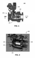
- FIG. 1 illustrates a side-sectional cut-away view of a flow control valve apparatus 100, in accordance with an embodiment. Note that identical parts or elements are generally indicated by identical reference numerals herein.
- the flow control valve apparatus 100 includes an actuator 106 disposed above a central body 103, which contains or houses a valve sleeve 102 (not shown in FIG. 2 ) and an expansion sleeve 108.
- the central body can house a gear 104, and the valve sleeve 102 and the expansion sleeve 108.
- the sets of double arrows shown in FIG. 1 indicate that the flow control valve apparatus 100 operates bidirectional fluid flow. That is, the flow control valve apparatus 100 is subject to bidirectional operation.
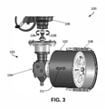
- FIG. 2 illustrates a cut-away perspective view of the flow control valve apparatus depicted in FIG. 1 , in accordance with an embodiment.
- the valve sleeve 102 is shown in FIG. 2 with respect to the expansion sleeve 108.
- the valve sleeve 102 as shown in FIG. 2 can be located to the right of the valve 104 within the central body 103.
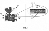
- FIG. 3 illustrates an operational view of the flow control valve apparatus 100 depicted in FIG. 1 and FIG. 2 , in accordance with an embodiment.
- the functionality of the flow control valve apparatus 100 is depicted in FIG. 3 .
- arrow 111 shown in FIG. 3 can indicate the bidirectional flow of fluid within the flow control valve apparatus 100.
- the expansion sleeve 108 is depicted in FIG. 3 as surrounding the valve sleeve 102.
- Arrows 106 and 109 can indicate a direction of movement of the actuator 106.
- FIG. 4 illustrates a schematic diagram depicting the flow control valve apparatus 100 with the expansion sleeve 108 having noise reduction properties, in accordance with an embodiment.
- the FIG. 4 diagram illustrates the flow control valve apparatus 100 to the left of the larger view of an inset portion 121 that shown at the right side of FIG. 4 .
- the expansion sleeve 108 can include one or more layers including a layer of standard material such as a material 122 and a material 121, and another layer configured from a material 126 having a scalable volumetric porosity and enhanced noise reduction properties.
- Aluminum is an example of a material that can be used as material 126.
- the configuration shown in FIG. 4 can combine noise filtering within the flow control valve apparatus 100, which can help to reduce the noise issues at the source (i.e., valve).
- the expansion sleeve 108 can function as a volumetric expansion sleeve.
- FIG. 5 illustrates a flow chart of operations depicting logical operational steps of a method 200 of configuring a flow control valve apparatus with a volumetric expansion sleeve, in accordance with an example embodiment.
- a step or operation can be implemented to calculate a required KG-Value (i.e., the capacity of the valve) according to user conditions., which may depend on user or customer conditions.
- a step or operation can be implemented to calculate the needed free area (e.g., volumetric porosity) from trim dependent sizing.
- a step or operation can be implemented for the production of the customized trim.
- a step or operation can be implemented to lathe the grooves for gaskets and finishing of the trim.
- the term 'trim can relate to or may refer to an expansive sleeve.
- the trim is one of the main parts of a valve and responsible for quality of the valve.
- the term 'KG-Value' refers to a fixed term used in the gas disciplines.
- An example of 'KG-Value', has been defined in DIN EN 334 - 3.3.2.6. Note that DIN EN 334 is a European standard for gas pressure regulators.
- an embodiment of a computer program product includes a computer useable storage medium to store a computer readable program.
- the computer-useable or computer-readable storage medium can be an electronic, magnetic, optical, electromagnetic, infrared, or semiconductor system (or apparatus or device).
- Examples of non-transitory computer-useable and computer-readable storage media include a semiconductor or solid-state memory, magnetic tape, a removable computer diskette, a random access memory (RAM), a read-only memory (ROM), a rigid magnetic disk, and an optical disk.
- Current examples of optical disks include a compact disk with read only memory (CD-ROM), a compact disk with read/write (CD-R/W), a digital video disk (DVD), Flash memory, and so on.
- embodiments of the invention may be implemented entirely in hardware or in an implementation containing both hardware and software elements.
- the software may include but is not limited to firmware, resident software, microcode, etc.
- the functions noted in the blocks may occur out of the order noted in the figures.
- two blocks shown in succession may, in fact, be executed substantially concurrently, or the blocks may sometimes be executed in the reverse order, depending upon the functionality involved.
- each block of the block diagrams and/or flowchart illustration, and combinations of blocks in the block diagrams and/or flowchart illustration can be implemented by special purpose hardware-based systems that perform the specified functions or acts or carry out combinations of special purpose hardware and computer instructions.
Landscapes
- Engineering & Computer Science (AREA)
- General Engineering & Computer Science (AREA)
- Mechanical Engineering (AREA)
- Physics & Mathematics (AREA)
- Fluid Mechanics (AREA)
- Details Of Valves (AREA)
Abstract
Description
- Embodiments relate to industrial process control in manufacturing and processing facilities. Embodiments also relate to the regulation and control of fluid flow in manufacturing and processing facilities. Embodiments further relate to flow control valves utilized in industrial process control applications. Embodiments additionally relate to an expansion sleeve apparatus used in flow control valve applications.
- Industrial process control at manufacturing plants includes the use of a flow control valve (also referred to as a pressure reduction valve) for the regulation and control of the flow of fluid/gas. A control signal (e.g., pneumatic or electronic) can manipulate the flow control valve and position it to enable accurate control of fluid flow for achieving production requirements, while reducing unnecessary costs. This predictable process variable control can form a part of a control loops, for instance, in a production operation. The flow control valve can be designed to withstand harsh conditions, and used in, for example, oil and gas, power, petrochemical, steel and other manufacturing and industrial applications.
- Flow control valves used in industrial process control applications may emit a strong acoustic noise that can disturb the environment and create problems in the manufacturing or industrial operation. That is, the acoustic noise generated can impact other components and devices in a manufacturing plant along with affecting the human operators at the plant.
- Typically, flow conditioners and noise filters may be used between a flow control valve and a meter to both block the line of sight of noise travelling with the fluid and also effectively absorb them. This approach, however, can introduce additional and unwanted pressure drop in the flow. Some approaches to noise filtering that have been implemented involve the implementation of a silencer expansion sleeve. These devices typically can be constructed with three or more layers, which may be helpful in facilitating noise reduction. This approach, however, is very expensive and not always optimal for customer site conditions, particularly in facilities with multiple flow control valves.
- The following summary is provided to facilitate an understanding of some of the features of the disclosed embodiments and is not intended to be a full description. A full appreciation of the various aspects of the embodiments disclosed herein can be gained by taking the specification, claims, drawings, and abstract as a whole.
- It is, therefore, one aspect of the disclosed embodiments to provide for an expansion sleeve apparatus for use in flow control valve applications.
- It is another aspect of the disclosed embodiments to provide for an expansion sleeve apparatus with inbuilt noise reduction properties for use in flow control valve applications.
- It is a further aspect of the disclosed embodiments to provide for an expansion sleeve apparatus that provides for a scalable porosity and which can be configured based on a calculation of a KG-value (i.e., the capacity of the valve) according to user conditions.
- It is yet another aspect of the disclosed embodiments to provide for a volumetric expansion sleeve.
- The aforementioned aspects and other objectives can now be achieved as described herein.
- In an embodiment, an expansion sleeve apparatus can comprise at least one layer configured from a material having a scalable volumetric porosity and enhanced noise reduction properties, wherein the expansion sleeve surrounds a flow control valve that is operable with a bidirectional flow of fluid through the flow control valve.
- In an embodiment, the material can comprise metal foam.
- In an embodiment, the material can comprise a metal with scalable volumetric porosity.
- In an embodiment, the expansion sleeve can be configured with a plurality of grooves.
- In an embodiment, the expansion sleeve can be configured based on a determination of a capacity of the flow control valve.
- In an embodiment, the expansion sleeve can be operable based on a determination of a capacity of the flow control valve.
- In an embodiment, the expansion sleeve can be installed in the flow control valve.
- In an embodiment, a flow control valve apparatus can include a flow control valve operable with a bidirectional flow of fluid through the flow control valve, and an expansion sleeve associated with the flow control valve, wherein the expansion sleeve includes at least one layer configured from a material having a scalable volumetric porosity and enhanced noise reduction properties, wherein the expansion sleeve surrounds the flow control valve that is operable with the bidirectional flow of fluid through the flow control valve.
- In an embodiment, a method of operating a flow control valve, can involve operating a flow control valve with a bidirectional flow of fluid through the flow control valve, the flow control valve associated with an expansion sleeve comprising at least one layer configured from a material having a scalable volumetric porosity and enhanced noise reduction properties, wherein the expansion sleeve surrounds the flow control valve.
- The accompanying figures, in which like reference numerals refer to identical or functionally-similar elements throughout the separate views and which are incorporated in and form a part of the specification, further illustrate the present invention and, together with the detailed description of the invention, serve to explain the principles of the present invention.
-
FIG. 1 illustrates a side-sectional cut-away view of a flow control valve apparatus, in accordance with an embodiment; -
FIG. 2 illustrates a cut-away perspective view of the flow control valve apparatus depicted inFIG. 1 , in accordance with an embodiment; -
FIG. 3 illustrates an operational view of the flow control valve apparatus depicted inFIG. 1 and FIG. 2 , in accordance with an embodiment; -
FIG. 4 illustrates a schematic diagram depicting a flow control valve apparatus with an expansion sleeve with noise reduction, in accordance with an embodiment; and -
FIG. 5 illustrates a flow chart of operations depicting logical operational steps of a method of configuring a flow control valve apparatus with a volumetric expansion sleeve, in accordance with an example embodiment. - The particular values and configurations discussed in these non-limiting examples can be varied and are cited merely to illustrate one or more embodiments and are not intended to limit the scope thereof.
- Subject matter will now be described more fully hereinafter with reference to the accompanying drawings, which form a part hereof, and which show, by way of illustration, specific example embodiments. Subject matter may, however, be embodied in a variety of different forms and, therefore, covered or claimed subject matter is intended to be construed as not being limited to any example embodiments set forth herein; example embodiments are provided merely to be illustrative. Likewise, a reasonably broad scope for claimed or covered subject matter is intended. Among other issues, subject matter may be embodied as methods, devices, components, or systems. Accordingly, embodiments may, for example, take the form of hardware, software, firmware, or a combination thereof. The following detailed description is, therefore, not intended to be interpreted in a limiting sense.
- Throughout the specification and claims, terms may have nuanced meanings suggested or implied in context beyond an explicitly stated meaning. Likewise, phrases such as "in one embodiment" or "in an example embodiment" and variations thereof as utilized herein may not necessarily refer to the same embodiment and the phrase "in another embodiment" or "in another example embodiment" and variations thereof as utilized herein may or may not necessarily refer to a different embodiment. It is intended, for example, that claimed subject matter include combinations of example embodiments in whole or in part.
- In general, terminology may be understood, at least in part, from usage in context. For example, terms such as "and," "or," or "and/or" as used herein may include a variety of meanings that may depend, at least in part, upon the context in which such terms are used. Generally, "or" if used to associate a list, such as A, B, or C, is intended to mean A, B, and C, here used in the inclusive sense, as well as A, B, or C, here used in the exclusive sense. In addition, the term "one or more" as used herein, depending at least in part upon context, may be used to describe any feature, structure, or characteristic in a singular sense or may be used to describe combinations of features, structures, or characteristics in a plural sense. Similarly, terms such as "a," "an," or "the", again, may be understood to convey a singular usage or to convey a plural usage, depending at least in part upon context. In addition, the term "based on" may be understood as not necessarily intended to convey an exclusive set of factors and may, instead, allow for existence of additional factors not necessarily expressly described, again, depending at least in part on context.
- As discussed earlier flow control valves used in industrial process control applications may emit strong acoustic noise and vibrations that can disturb the environment and create problems in manufacturing or industrial operations. Flow conditioners and noise filters may be used between a flow control valve and a meter to block the line of sight of noise travelling with the fluid and also effectively absorb them. This approach, however, may introduce an additional and unwanted pressure drop in the flow.
- The disclosed embodiments can offer a solution to these problems by combining noise filtering aspect within the control valve to assist in reducing the noise issue at the source (i.e. flow control valve). This approach can be used to reduce the costs for an expansion sleeve and additional costs for noise reduction parts (e.g., metal foam). The embodiments can be used in bi-directional operation conditions, which is advantageous because most noise reduction installations function well only in one direction. This approach can potentially reduce the need for additional flow conditioners by providing a solution with inbuilt noise reduction, and which can be implemented in, for example, a pipe or between the valve and meter or expansive silencer, which may save additional costs.
-
FIG. 1 illustrates a side-sectional cut-away view of a flowcontrol valve apparatus 100, in accordance with an embodiment. Note that identical parts or elements are generally indicated by identical reference numerals herein. The flowcontrol valve apparatus 100 includes anactuator 106 disposed above acentral body 103, which contains or houses a valve sleeve 102 (not shown inFIG. 2 ) and anexpansion sleeve 108. The central body can house agear 104, and thevalve sleeve 102 and theexpansion sleeve 108. The sets of double arrows shown inFIG. 1 indicate that the flowcontrol valve apparatus 100 operates bidirectional fluid flow. That is, the flowcontrol valve apparatus 100 is subject to bidirectional operation. -
FIG. 2 illustrates a cut-away perspective view of the flow control valve apparatus depicted inFIG. 1 , in accordance with an embodiment. Thevalve sleeve 102 is shown inFIG. 2 with respect to theexpansion sleeve 108. Thevalve sleeve 102 as shown inFIG. 2 can be located to the right of thevalve 104 within thecentral body 103. -
FIG. 3 illustrates an operational view of the flowcontrol valve apparatus 100 depicted inFIG. 1 and FIG. 2 , in accordance with an embodiment. The functionality of the flowcontrol valve apparatus 100 is depicted inFIG. 3 . For example,arrow 111 shown inFIG. 3 can indicate the bidirectional flow of fluid within the flowcontrol valve apparatus 100. Theexpansion sleeve 108 is depicted inFIG. 3 as surrounding thevalve sleeve 102.Arrows actuator 106. -
FIG. 4 illustrates a schematic diagram depicting the flowcontrol valve apparatus 100 with theexpansion sleeve 108 having noise reduction properties, in accordance with an embodiment. TheFIG. 4 diagram illustrates the flowcontrol valve apparatus 100 to the left of the larger view of aninset portion 121 that shown at the right side ofFIG. 4 . - The
expansion sleeve 108 can include one or more layers including a layer of standard material such as amaterial 122 and amaterial 121, and another layer configured from amaterial 126 having a scalable volumetric porosity and enhanced noise reduction properties. Aluminum is an example of a material that can be used asmaterial 126. The configuration shown inFIG. 4 can combine noise filtering within the flowcontrol valve apparatus 100, which can help to reduce the noise issues at the source (i.e., valve). By using material such as thematerial 126 shown inFIG. 4 , theexpansion sleeve 108 can function as a volumetric expansion sleeve. -
FIG. 5 illustrates a flow chart of operations depicting logical operational steps of amethod 200 of configuring a flow control valve apparatus with a volumetric expansion sleeve, in accordance with an example embodiment. As shown atblock 201, a step or operation can be implemented to calculate a required KG-Value (i.e., the capacity of the valve) according to user conditions., which may depend on user or customer conditions. Then, as illustrated atblock 202, a step or operation can be implemented to calculate the needed free area (e.g., volumetric porosity) from trim dependent sizing. Thereafter, as shown atblock 203, a step or operation can be implemented for the production of the customized trim. Finally, as shown atblock 204, a step or operation can be implemented to lathe the grooves for gaskets and finishing of the trim. - As utilized herein the term 'trim" can relate to or may refer to an expansive sleeve. The trim is one of the main parts of a valve and responsible for quality of the valve. The term 'KG-Value' refers to a fixed term used in the gas disciplines. An example of 'KG-Value', has been defined in DIN EN 334 - 3.3.2.6. Note that DIN EN 334 is a European standard for gas pressure regulators.
- Although the operations of the method(s) herein are shown and described in a particular order, the order of the operations of each method may be altered so that certain operations may be performed in an inverse order or so that certain operations may be performed, at least in part, concurrently with other operations. In another embodiment, instructions or sub-operations of distinct operations may be implemented in an intermittent and/or alternating manner.
- It should also be noted that at least some of the operations for the methods described herein may be implemented using software instructions stored on a computer useable storage medium for execution by a computer including, for example, a microcontroller as discussed herein. As an example, an embodiment of a computer program product includes a computer useable storage medium to store a computer readable program.
- The computer-useable or computer-readable storage medium can be an electronic, magnetic, optical, electromagnetic, infrared, or semiconductor system (or apparatus or device). Examples of non-transitory computer-useable and computer-readable storage media include a semiconductor or solid-state memory, magnetic tape, a removable computer diskette, a random access memory (RAM), a read-only memory (ROM), a rigid magnetic disk, and an optical disk. Current examples of optical disks include a compact disk with read only memory (CD-ROM), a compact disk with read/write (CD-R/W), a digital video disk (DVD), Flash memory, and so on.
- Alternatively, embodiments of the invention may be implemented entirely in hardware or in an implementation containing both hardware and software elements. In embodiments that do utilize software, the software may include but is not limited to firmware, resident software, microcode, etc.
- In some alternative implementations, the functions noted in the blocks may occur out of the order noted in the figures. For example, two blocks shown in succession may, in fact, be executed substantially concurrently, or the blocks may sometimes be executed in the reverse order, depending upon the functionality involved. It will also be noted that each block of the block diagrams and/or flowchart illustration, and combinations of blocks in the block diagrams and/or flowchart illustration, can be implemented by special purpose hardware-based systems that perform the specified functions or acts or carry out combinations of special purpose hardware and computer instructions.
- It will be appreciated that variations of the above-disclosed embodiments and examples and other features and functions, or alternatives thereof, may be desirably combined into many other different systems or applications. It will also be appreciated that various presently unforeseen or unanticipated alternatives, modifications, variations or improvements therein may be subsequently made by those skilled in the art which are also intended to be encompassed by the following claims.
Claims (10)
- An expansion sleeve apparatus, comprising:
an expansion sleeve comprising at least one layer configured from a material having a scalable volumetric porosity and enhanced noise reduction properties, wherein the expansion sleeve surrounds a flow control valve that is operable with a bidirectional flow of fluid through the flow control valve. - The expansion sleeve apparatus of claim 1 wherein the material comprises a metal foam.
- The expansion sleeve of claim 1 wherein the material comprises a metal with scalable volumetric porosity.
- The expansion sleeve apparatus of claim 1 wherein the expansion sleeve is configured with a plurality of grooves.
- The expansion sleeve apparatus of claim 1 wherein the expansion sleeve is installed in the flow control valve.
- A flow control valve apparatus, comprising:a flow control valve operable with a bidirectional flow of fluid through the flow control valve; andan expansion sleeve associated with the flow control valve, wherein the expansion sleeve includes at least one layer configured from a material having a scalable volumetric porosity and enhanced noise reduction properties, wherein the expansion sleeve surrounds the flow control valve that is operable with the bidirectional flow of fluid through the flow control valve.
- The flow control valve apparatus of claim 6 wherein the material comprises a metal with scalable volumetric porosity.
- The flow control valve apparatus of claim 6 wherein the expansion sleeve is configured based on a determination of a capacity of the flow control valve.
- A method of operating a flow control valve, comprising:
operating a flow control valve with a bidirectional flow of fluid through the flow control valve, the flow control valve associated with an expansion sleeve comprising at least one layer configured from a material having a scalable volumetric porosity and enhanced noise reduction properties, wherein the expansion sleeve surrounds the flow control valve. - The method of claim 9 wherein the expansion sleeve is configured based on a determination of a capacity of the flow control valve.
Applications Claiming Priority (2)
| Application Number | Priority Date | Filing Date | Title |
|---|---|---|---|
| US202063036185P | 2020-06-08 | 2020-06-08 | |
| US17/026,182 US12152696B2 (en) | 2020-06-08 | 2020-09-19 | Expansion sleeve apparatus and method for flow control valve |
Publications (1)
| Publication Number | Publication Date |
|---|---|
| EP3971453A1 true EP3971453A1 (en) | 2022-03-23 |
Family
ID=78817189
Family Applications (1)
| Application Number | Title | Priority Date | Filing Date |
|---|---|---|---|
| EP21196155.2A Withdrawn EP3971453A1 (en) | 2020-06-08 | 2021-09-10 | Expansion sleeve apparatus and method for flow control valve |
Country Status (3)
| Country | Link |
|---|---|
| US (1) | US12152696B2 (en) |
| EP (1) | EP3971453A1 (en) |
| CN (1) | CN114251511A (en) |
Citations (4)
| Publication number | Priority date | Publication date | Assignee | Title |
|---|---|---|---|---|
| US5161576A (en) * | 1990-02-13 | 1992-11-10 | System Engineering & Components International, B.V. | Valve provided with sound-reducing means |
| US20070017584A1 (en) * | 2005-07-19 | 2007-01-25 | Spx Corporation | Fluid trim apparatus and method |
| CN102840366A (en) * | 2012-09-17 | 2012-12-26 | 大连派思燃气系统股份有限公司 | Erosive wear-proof gas pressure regulator |
| CN209309448U (en) * | 2018-11-30 | 2019-08-27 | 博纳斯威阀门股份有限公司 | A kind of single shaft lead screw flow control valve |
Family Cites Families (23)
| Publication number | Priority date | Publication date | Assignee | Title |
|---|---|---|---|---|
| US3990475A (en) | 1975-01-08 | 1976-11-09 | Honeywell Inc. | Low noise valve trim |
| US4161967A (en) | 1978-02-03 | 1979-07-24 | The Babcock & Wilcox Company | Thermal sleeve |
| US4402485A (en) * | 1981-06-11 | 1983-09-06 | Fisher Controls Company, Inc. | Eccentrically nested tube gas line silencer |
| US5261453A (en) * | 1989-02-13 | 1993-11-16 | System Engineering And Components International B.V. | Valve provided with sound-reducing means |
| JPH08247336A (en) * | 1995-03-09 | 1996-09-27 | Motoyama Seisakusho:Kk | Regulating valve and piping |
| JP3977066B2 (en) * | 2001-12-03 | 2007-09-19 | 株式会社テージーケー | Solenoid proportional valve |
| US20030196698A1 (en) | 2002-04-17 | 2003-10-23 | Metal Industries Research & Development Centre | Axial flow control valve |
| US6968923B2 (en) * | 2003-07-30 | 2005-11-29 | Control Components, Inc. | Reduced noise valve stack connection |
| TW200636198A (en) * | 2004-12-30 | 2006-10-16 | Twister Bv | Throttling valve and method for enlarging liquid droplet sizes in a fluid stream flowing therethrough |
| GB0716363D0 (en) * | 2007-08-22 | 2007-10-03 | Ct For Sustainable Engineering | Fluid control device |
| JP2009052622A (en) | 2007-08-24 | 2009-03-12 | Aisan Ind Co Ltd | Antinoise structure for flow rate control valve |
| US8205632B2 (en) | 2008-05-02 | 2012-06-26 | Bifold Fluidpower Limited | Fluid flow control device |
| CN201373173Y (en) * | 2009-03-03 | 2009-12-30 | 大连亨利测控仪表工程有限公司 | Anti-cavitation high differential pressure control valve |
| CN201687947U (en) | 2009-07-23 | 2010-12-29 | 上海三洲自控仪表有限公司 | Low-noise high-performance control valve |
| MY165246A (en) * | 2009-07-30 | 2018-03-14 | Twister Bv | Tapered throttling valve |
| CN202852181U (en) | 2012-10-16 | 2013-04-03 | 赖明全 | Independent control valve |
| JP6302717B2 (en) * | 2014-03-27 | 2018-03-28 | 株式会社不二工機 | Motorized valve |
| US10094489B2 (en) | 2015-02-03 | 2018-10-09 | Control Components, Inc. | Axial resistance valve trim design |
| CN105650338A (en) * | 2015-12-17 | 2016-06-08 | 高卫兵 | Axial flow type safety cut-off valve |
| TWM549293U (en) | 2017-05-23 | 2017-09-21 | 東莞紘昌塑膠五金照明制品有限公司 | Tube assembly for delivering a substance |
| US10543538B2 (en) | 2017-11-27 | 2020-01-28 | Kennametal Inc. | Expansion sleeves and associated chucks |
| CN108131455A (en) * | 2018-02-12 | 2018-06-08 | 无锡智能自控工程股份有限公司 | High Pressure Difference axial flow control valve |
| CN110836207A (en) * | 2019-11-15 | 2020-02-25 | 冯森蕾 | Bidirectional overflow valve |
-
2020
- 2020-09-19 US US17/026,182 patent/US12152696B2/en active Active
-
2021
- 2021-09-10 CN CN202111065846.XA patent/CN114251511A/en active Pending
- 2021-09-10 EP EP21196155.2A patent/EP3971453A1/en not_active Withdrawn
Patent Citations (4)
| Publication number | Priority date | Publication date | Assignee | Title |
|---|---|---|---|---|
| US5161576A (en) * | 1990-02-13 | 1992-11-10 | System Engineering & Components International, B.V. | Valve provided with sound-reducing means |
| US20070017584A1 (en) * | 2005-07-19 | 2007-01-25 | Spx Corporation | Fluid trim apparatus and method |
| CN102840366A (en) * | 2012-09-17 | 2012-12-26 | 大连派思燃气系统股份有限公司 | Erosive wear-proof gas pressure regulator |
| CN209309448U (en) * | 2018-11-30 | 2019-08-27 | 博纳斯威阀门股份有限公司 | A kind of single shaft lead screw flow control valve |
Also Published As
| Publication number | Publication date |
|---|---|
| CN114251511A (en) | 2022-03-29 |
| US12152696B2 (en) | 2024-11-26 |
| US20210381622A1 (en) | 2021-12-09 |
Similar Documents
| Publication | Publication Date | Title |
|---|---|---|
| Findeisen et al. | Assessment and future directions of nonlinear model predictive control | |
| Imaduddin et al. | A high performance magnetorheological valve with a meandering flow path | |
| CN211901789U (en) | Non-clogging multi-stage cages, non-clogging multi-stage valve trims, and fluid flow control devices | |
| Wetter | Fan and pump model that has a unique solution for any pressure boundary condition and control signal | |
| Herty | Modeling, simulation and optimization of gas networks with compressors | |
| US12152696B2 (en) | Expansion sleeve apparatus and method for flow control valve | |
| JP6014709B2 (en) | Automatic bidirectional expansion valve | |
| US20140314543A1 (en) | Compressor system and method of controlling the same | |
| CN105045986B (en) | The Optimization Design for the composite damping gap magnetorheological damping unit that performance is oriented to | |
| Sotoodeh | Noise and acoustic fatigue analysis in valves (case study of noise analysis and reduction for a 12 ″× 10 ″pressure safety valve) | |
| Lamaddalena et al. | A new indicator for unsteady flow analysis in pressurized irrigation systems | |
| KR101956177B1 (en) | Muffler of air conditioning system for vehicles | |
| CN105160053B (en) | A kind of optimum design method for the magnetorheological damping unit that performance is oriented to | |
| JP5715754B2 (en) | Four-way selector valve | |
| Pang et al. | Integrated servo-mechanical control systems design using Nyquist plots for high-performance mechatronics | |
| CN103206205A (en) | A method for predicting the life of a tubing string | |
| CN202501681U (en) | Electronic expansion valve and throttle mechanism mounting structure with electronic expansion valve air conditioner | |
| EP3715688B1 (en) | Integrated valve | |
| JP5128304B2 (en) | Pressure control device | |
| CN103216979B (en) | Reducing two-way throttling short tube | |
| US20200032813A1 (en) | Electromechanical actuators for refrigerant flow control | |
| Ji et al. | Active Control of Noise Propagated through Ventilation Openings of Enclosures Using an FIR Filter | |
| JP7333905B2 (en) | pipe silencer | |
| Kim et al. | Transient Response Analysis of a Control Valve for CO 2 Refrigerant | |
| Thawani et al. | Flow-induced tones in automotive refrigerant systems |
Legal Events
| Date | Code | Title | Description |
|---|---|---|---|
| PUAI | Public reference made under article 153(3) epc to a published international application that has entered the european phase |
Free format text: ORIGINAL CODE: 0009012 |
|
| STAA | Information on the status of an ep patent application or granted ep patent |
Free format text: STATUS: REQUEST FOR EXAMINATION WAS MADE |
|
| 17P | Request for examination filed |
Effective date: 20210910 |
|
| AK | Designated contracting states |
Kind code of ref document: A1 Designated state(s): AL AT BE BG CH CY CZ DE DK EE ES FI FR GB GR HR HU IE IS IT LI LT LU LV MC MK MT NL NO PL PT RO RS SE SI SK SM TR |
|
| STAA | Information on the status of an ep patent application or granted ep patent |
Free format text: STATUS: EXAMINATION IS IN PROGRESS |
|
| 17Q | First examination report despatched |
Effective date: 20230126 |
|
| P01 | Opt-out of the competence of the unified patent court (upc) registered |
Effective date: 20230414 |
|
| STAA | Information on the status of an ep patent application or granted ep patent |
Free format text: STATUS: THE APPLICATION IS DEEMED TO BE WITHDRAWN |
|
| 18D | Application deemed to be withdrawn |
Effective date: 20250301 |